11 Shell Structures
25
Miller, C.D. “Shell Structures” Structural Engineering Handbook Ed. Chen Wai-Fah Boca Raton: CRC Press LLC, 1999
-
Upload
albertjopson -
Category
Documents
-
view
67 -
download
0
Transcript of 11 Shell Structures
Miller, C.D. “Shell Structures”Structural Engineering HandbookEd. Chen Wai-FahBoca Raton: CRC Press LLC, 1999
Shell Structures
Clarence D. MillerConsulting Engineer,Bloomington, IN
11.1 IntroductionOverview • Production Practice • Scope • Limitations • StressComponents for StabilityAnalysis andDesign • Materials • Ge-ometries, Failure Modes, and Loads • Buckling Design Method• Stress Factor • Nomenclature
11.2 Allowable Compressive Stresses for Cylindrical ShellsUniform Axial Compression • Axial Compression Due toBending Moment • External Pressure • Shear • Sizing of Rings(General Instability)
11.3 Allowable Compressive Stresses For ConesUniform Axial Compression and Axial CompressionDue to Bending • External Pressure • Shear • Local StiffenerBuckling
11.4 Allowable Stress Equations For Combined LoadsFor Combination of Uniform Axial Compression and HoopCompression • For Combination of Axial Compression Dueto Bending Moment, M , and Hoop Compression • For Com-bination of Hoop Compression and Shear • For Combinationof Uniform Axial Compression, Axial Compression Due toBending Moment, M , and Shear, in the Presence of HoopCompression, (fh 6= 0) • For Combination of Uniform AxialCompression, Axial Compression Due to Bending Moment,M , and Shear, in the Absence of Hoop Compression, (fh = 0)
11.5 Tolerances for Cylindrical and Conical ShellsShells Subjected to Uniform Axial Compression and AxialCompression Due to Bending Moment • Shells Subjected toExternal Pressure • Shells Subjected to Shear
11.6 Allowable Compressive StressesSpherical Shells • Toroidal and Ellipsoidal Heads
11.7 Tolerances for Formed HeadsReferencesFurther Reading
11.1 Introduction
11.1.1 Overview
Many steel structures, such as elevated water tanks, oil and water storage tanks, offshore structures,and pressure vessels, are comprised of shell elements that are subjected to compression stresses. Theshell elements are subject to instability resulting from the applied loads. The theoretical bucklingstrength based on linear elastic bifurcation analysis is well known for stiffened as well as unstiffenedcylindrical and conical shells and unstiffened spherical and torispherical shells. Simple formulas
c©1999 by CRC Press LLC
have been determined for many geometries and types of loads. Initial geometric imperfections andresidual stresses that result from the fabrication process, however, reduce the buckling strength offabricated shells. The amount of reduction is dependent on the geometry of the shell, type of loading(axial compression, bending, external pressure, etc.), size of imperfections, and material properties.
11.1.2 Production Practice
The behavior of a cylindrical shell is influenced to some extent by whether it is manufactured in a pipeor tubing mill or fabricated from plate material. The two methods of production will be referred toas manufactured cylinders and fabricated cylinders. The distinction is important primarily becauseof the differences in geometric imperfections and residual stress levels that may result from the twodifferent production practices. In general, fabricated cylinders may be expected to have considerablylarger magnitudes of imperfections (in out-of-roundness and lack of straightness) than the millmanufactured products. Similarly, fabricated heads are likely to have larger shape imperfections thanthose produced by spinning. Spun heads, however, typically have a greater variation in thicknessand greater residual stresses due to the cold working. The design rules given in this chapter apply tofabricated steel shells.
Fabricated shells are produced from flat plates by rolling or pressing the plates to the desired shapeand welding the edges together. Because of the method of construction, the mechanical propertiesof the shells will vary along the length and around the circumference. Misfit of the edges to bewelded together may result in unintentional eccentricities at the joints. In addition, welding tends tointroduce out-of-roundness and out-of-straightness imperfections that must be taken into accountin the design rules.
11.1.3 Scope
Rules are given for determining the allowable compressive stresses for unstiffened and ring stiffenedcircular cylinders and cones and unstiffened spherical, ellipsoidal, and torispherical heads. Theallowable stress equations are based on theoretical buckling equations that have been reduced byknockdown factors and by plasticity reduction factors that were determined from tests on fabricatedshells. The research leading to the development of the allowable stress equations is given in [2, 7, 8,9, 10].
Allowable compressive stress equations are presented for cylinders and cones subjected to uniformaxial compression, bending moment applied over the entire cross-section, external pressure, loadsthat produce in-plane shear stresses, and combinations of these loads. Allowable compressive stressequations are presented for formed heads that are subjected to loads that produce unequal biaxialstresses as well as equal biaxial stresses.
11.1.4 Limitations
The allowable stress equations are based on an assumed axisymmetric shell with uniform thicknessfor unstiffened cylinders and formed heads and with uniform thickness between rings for stiffenedcylinders and cones. All shell penetrations must be properly reinforced. The results of tests onreinforced openings and some design guidance are given in [6]. The stability criteria of this chaptermaybeused for cylinders that are reinforced inaccordancewith the recommendationsof this referenceif the openings do not exceed 10% of the cylinder diameter or 80% of the ring spacing. Specialconsideration must be given to the effects of larger penetrations.
The proposed rules are applicable to shells with D/t ratios up to 2000 and shell thicknesses of 3/16in. or greater. The deviations from true circular shape and straightness must satisfy the requirementsstated in this chapter.
c©1999 by CRC Press LLC
Special consideration must be given to ends of members or areas of load application where stressdistribution may be nonlinear and localized stresses may exceed those predicted by linear theory.When the localized stresses extend over a distance equal to one half the wave length of the bucklingmode, they should be considered as a uniform stress around the full circumference. Additionalthickness or stiffening may be required.
Failure due to material fracture or fatigue and failures caused by dents resulting from accidentalloads are not considered. The rules do not apply to temperatures where creep may occur.
11.1.5 Stress Components for Stability Analysis and Design
The internal stress field that controls the buckling of a cylindrical shell consists of the longitudinal,circumferential, and in-plane shearmembrane stresses. The stresses resulting fromadynamic analysisshould be treated as equivalent static stresses.
11.1.6 Materials
Steel
The allowable stress equations apply directly to shells fabricated from carbon and low alloysteel plate materials such as those given in Table 11.1 or Table UCS-23 of [3]. The steel materialsin Table 11.1 are designated by group and class. Steels are grouped according to strength level andwelding characteristics. Group I designates mild steels with specified minimum yield stresses ≤ 40ksi and these steels may be welded by any of the processes as described in [5]. Group II designatesintermediate strength steels with specified minimum yield stresses > 40 ksi and ≤ 52 ksi. These steelsrequire the use of low hydrogen welding processes. Group III designates high strength steels withspecified minimum yield stresses > 52 ksi. These steels may be used provided that each applicationis investigated with respect to weldability and special welding procedures that may be required.Consideration should be given to fatigue problems that may result from the use of higher workingstresses, and notch toughness in relation to other elements of fracture control such as fabrication,inspection procedures, service stress, and temperature environment.
The steels in Table 11.1 have been classified according to their notch toughness characteristics.Class C steels are those that have a history of successful application in welded structures at servicetemperatures above freezing. Impact tests are not specified. Class B steels are suitable for usewhere thickness, cold work, restraint, stress concentration, and impact loading indicate the need forimproved notch toughness. When impact tests are specified, Class B steels should exhibit CharpyV-notch energy of 15 ft-lbs for Group 1 and 25 ft-lbs for Group II at the lowest service temperature.The Class B steels given in Table 11.1 can generally meet the Charpy requirements at temperaturesranging from 50◦ to 32◦F. Class A steels are suitable for use at subfreezing temperatures and for criticalapplications involving adverse combinations of the factors cited above. The steels given in Table 11.1can generally meet the Charpy requirements for Class B steels at temperatures ranging from −4◦ to−40◦F.
Other Materials
The design equations can also be applied to other materials for which a chart or table is providedin Subpart 3 of [4] by substituting the tangent modulus Et for the elastic modulus E in the allowablestress equations. The method for finding the allowable stresses for shells constructed from thesematerials is determined by the following procedure.
c©1999 by CRC Press LLC
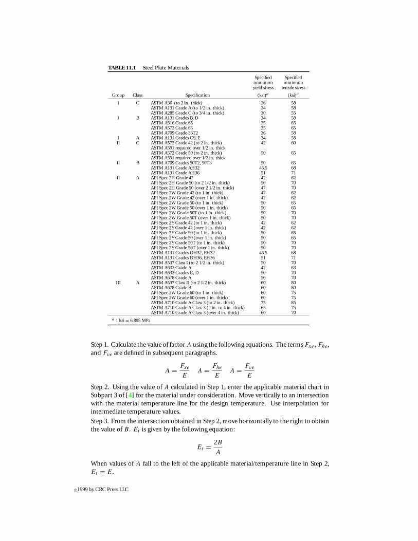
TABLE 11.1 Steel Plate Materials
Specified Specifiedminimum minimumyield stress tensile stress
Group Class Specification (ksi)a (ksi)a
I C ASTM A36 (to 2 in. thick) 36 58ASTM A131 Grade A (to 1/2 in. thick) 34 58ASTM A285 Grade C (to 3/4 in. thick) 30 55
I B ASTM A131 Grades B, D 34 58ASTM A516 Grade 65 35 65ASTM A573 Grade 65 35 65ASTM A709 Grade 36T2 36 58
I A ASTM A131 Grades CS, E 34 58II C ASTM A572 Grade 42 (to 2 in. thick) 42 60
ASTM A591 required over 1/2 in. thickASTM A572 Grade 50 (to 2 in. thick) 50 65ASTM A591 required over 1/2 in. thick
II B ASTM A709 Grades 50T2, 50T3 50 65ASTM A131 Grade AH32 45.5 68ASTM A131 Grade AH36 51 71
II A API Spec 2H Grade 42 42 62API Spec 2H Grade 50 (to 2 1/2 in. thick) 50 70API Spec 2H Grade 50 (over 2 1/2 in. thick) 47 70API Spec 2W Grade 42 (to 1 in. thick) 42 62API Spec 2W Grade 42 (over 1 in. thick) 42 62API Spec 2W Grade 50 (to 1 in. thick) 50 65API Spec 2W Grade 50 (over 1 in. thick) 50 65API Spec 2W Grade 50T (to 1 in. thick) 50 70API Spec 2W Grade 50T (over 1 in. thick) 50 70API Spec 2Y Grade 42 (to 1 in. thick) 42 62API Spec 2Y Grade 42 (over 1 in. thick) 42 62API Spec 2Y Grade 50 (to 1 in. thick) 50 65API Spec 2Y Grade 50 (over 1 in. thick) 50 65API Spec 2Y Grade 50T (to 1 in. thick) 50 70API Spec 2Y Grade 50T (over 1 in. thick) 50 70ASTM A131 Grades DH32, EH32 45.5 68ASTM A131 Grades DH36, EH36 51 71ASTM A537 Class I (to 2 1/2 in. thick) 50 70ASTM A633 Grade A 42 63ASTM A633 Grades C, D 50 70ASTM A678 Grade A 50 70
III A ASTM A537 Class II (to 2 1/2 in. thick) 60 80ASTM A678 Grade B 60 80API Spec 2W Grade 60 (to 1 in. thick) 60 75API Spec 2W Grade 60 (over 1 in. thick) 60 75ASTM A710 Grade A Class 3 (to 2 in. thick) 75 85ASTM A710 Grade A Class 3 (2 in. to 4 in. thick) 65 75ASTM A710 Grade A Class 3 (over 4 in. thick) 60 70
a 1 ksi = 6.895 MPa
Step 1. Calculate the value of factor A using the following equations. The terms Fxe, Fhe,and Fve are defined in subsequent paragraphs.
A = Fxe
EA = Fhe
EA = Fve
E
Step 2. Using the value of A calculated in Step 1, enter the applicable material chart inSubpart 3 of [4] for the material under consideration. Move vertically to an intersectionwith the material temperature line for the design temperature. Use interpolation forintermediate temperature values.
Step 3. From the intersection obtained in Step 2, move horizontally to the right to obtainthe value of B. Et is given by the following equation:
Et = 2B
A
When values of A fall to the left of the applicable material/temperature line in Step 2,Et = E.
c©1999 by CRC Press LLC
Step 4. Calculate the allowable stresses from the following equations:
Fxa = Fxe
FS
Et
EFba = Fxa Fha = Fhe
FS
Et
EFva = Fve
FS
Et
E
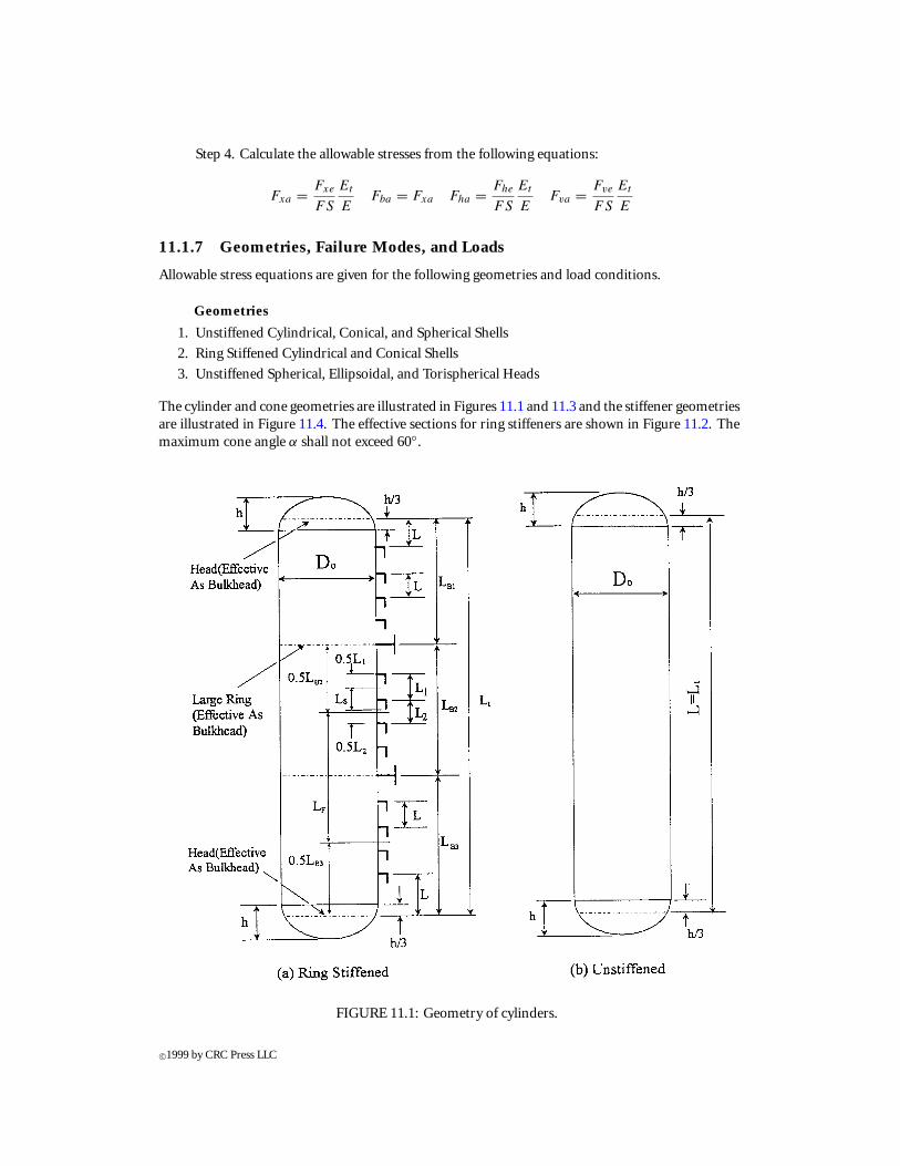
11.1.7 Geometries, Failure Modes, and Loads
Allowable stress equations are given for the following geometries and load conditions.
Geometries
1. Unstiffened Cylindrical, Conical, and Spherical Shells
2. Ring Stiffened Cylindrical and Conical Shells
3. Unstiffened Spherical, Ellipsoidal, and Torispherical Heads
The cylinder and cone geometries are illustrated in Figures 11.1 and 11.3 and the stiffener geometriesare illustrated in Figure 11.4. The effective sections for ring stiffeners are shown in Figure 11.2. Themaximum cone angle α shall not exceed 60◦.
FIGURE 11.1: Geometry of cylinders.
c©1999 by CRC Press LLC
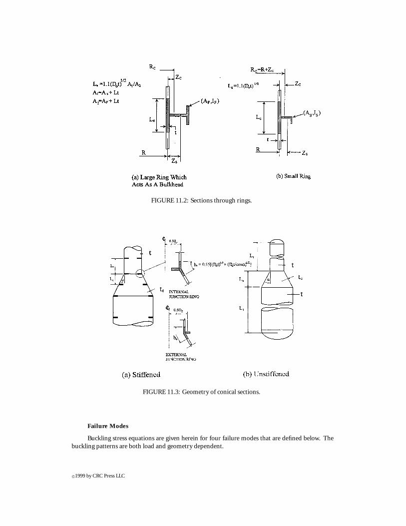
FIGURE 11.2: Sections through rings.
FIGURE 11.3: Geometry of conical sections.
Failure Modes
Buckling stress equations are given herein for four failure modes that are defined below. Thebuckling patterns are both load and geometry dependent.
c©1999 by CRC Press LLC
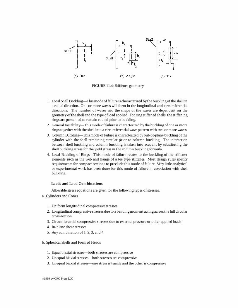
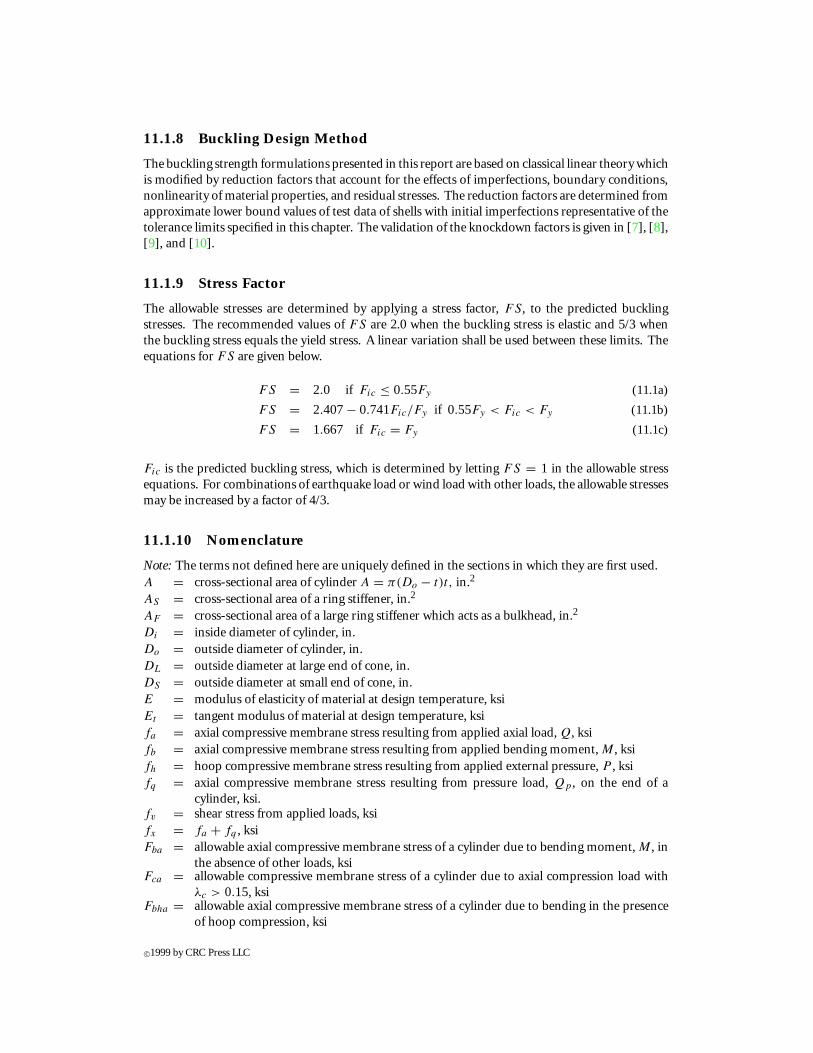
FIGURE 11.4: Stiffener geometry.
1. Local Shell Buckling—This mode of failure is characterized by the buckling of the shell ina radial direction. One or more waves will form in the longitudinal and circumferentialdirections. The number of waves and the shape of the waves are dependent on thegeometry of the shell and the type of load applied. For ring stiffened shells, the stiffeningrings are presumed to remain round prior to buckling.
2. General Instability—This mode of failure is characterized by the buckling of one or morerings together with the shell into a circumferential wave pattern with two or more waves.
3. Column Buckling—This mode of failure is characterized by out-of-plane buckling of thecylinder with the shell remaining circular prior to column buckling. The interactionbetween shell buckling and column buckling is taken into account by substituting theshell buckling stress for the yield stress in the column buckling formula.
4. Local Buckling of Rings—This mode of failure relates to the buckling of the stiffenerelements such as the web and flange of a tee type stiffener. Most design rules specifyrequirements for compact sections to preclude this mode of failure. Very little analyticalor experimental work has been done for this mode of failure in association with shellbuckling.
Loads and Load Combinations
Allowable stress equations are given for the following types of stresses.
a. Cylinders and Cones
1. Uniform longitudinal compressive stresses
2. Longitudinal compressive stresses due to a bending moment acting across the full circularcross-section
3. Circumferential compressive stresses due to external pressure or other applied loads
4. In-plane shear stresses
5. Any combination of 1, 2, 3, and 4
b. Spherical Shells and Formed Heads
1. Equal biaxial stresses—both stresses are compressive
2. Unequal biaxial stresses—both stresses are compressive
3. Unequal biaxial stresses—one stress is tensile and the other is compressive
c©1999 by CRC Press LLC
11.1.8 Buckling Design Method
The buckling strength formulations presented in this report are based on classical linear theory whichis modified by reduction factors that account for the effects of imperfections, boundary conditions,nonlinearity of material properties, and residual stresses. The reduction factors are determined fromapproximate lower bound values of test data of shells with initial imperfections representative of thetolerance limits specified in this chapter. The validation of the knockdown factors is given in [7], [8],[9], and [10].
11.1.9 Stress Factor
The allowable stresses are determined by applying a stress factor, FS, to the predicted bucklingstresses. The recommended values of FS are 2.0 when the buckling stress is elastic and 5/3 whenthe buckling stress equals the yield stress. A linear variation shall be used between these limits. Theequations for FS are given below.
FS = 2.0 if Fic ≤ 0.55Fy (11.1a)
FS = 2.407− 0.741Fic/Fy if 0.55Fy < Fic < Fy (11.1b)
FS = 1.667 if Fic = Fy (11.1c)
Fic is the predicted buckling stress, which is determined by letting FS = 1 in the allowable stressequations. For combinations of earthquake load or wind load with other loads, the allowable stressesmay be increased by a factor of 4/3.
11.1.10 Nomenclature
Note: The terms not defined here are uniquely defined in the sections in which they are first used.A = cross-sectional area of cylinder A = π(Do − t)t, in.2
AS = cross-sectional area of a ring stiffener, in.2
AF = cross-sectional area of a large ring stiffener which acts as a bulkhead, in.2
Di = inside diameter of cylinder, in.Do = outside diameter of cylinder, in.DL = outside diameter at large end of cone, in.DS = outside diameter at small end of cone, in.E = modulus of elasticity of material at design temperature, ksiEt = tangent modulus of material at design temperature, ksifa = axial compressive membrane stress resulting from applied axial load, Q, ksifb = axial compressive membrane stress resulting from applied bending moment, M , ksifh = hoop compressive membrane stress resulting from applied external pressure, P , ksifq = axial compressive membrane stress resulting from pressure load, Qp , on the end of a
cylinder, ksi.fv = shear stress from applied loads, ksifx = fa + fq , ksiFba = allowable axial compressive membrane stress of a cylinder due to bending moment, M , in
the absence of other loads, ksiFca = allowable compressive membrane stress of a cylinder due to axial compression load with
λc > 0.15, ksiFbha = allowable axial compressive membrane stress of a cylinder due to bending in the presence
of hoop compression, ksi
c©1999 by CRC Press LLC
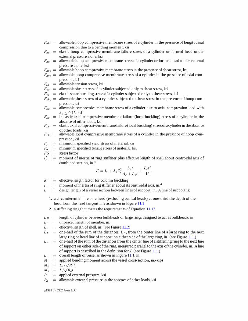
Fhba = allowable hoop compressive membrane stress of a cylinder in the presence of longitudinalcompression due to a bending moment, ksi
Fhe = elastic hoop compressive membrane failure stress of a cylinder or formed head underexternal pressure alone, ksi
Fha = allowable hoop compressive membrane stress of a cylinder or formed head under externalpressure alone, ksi
Fhva = allowable hoop compressive membrane stress in the presence of shear stress, ksiFhxa = allowable hoop compressive membrane stress of a cylinder in the presence of axial com-
pression, ksiFta = allowable tension stress, ksiFva = allowable shear stress of a cylinder subjected only to shear stress, ksiFve = elastic shear buckling stress of a cylinder subjected only to shear stress, ksiFvha = allowable shear stress of a cylinder subjected to shear stress in the presence of hoop com-
pression, ksiFxa = allowable compressive membrane stress of a cylinder due to axial compression load with
λc ≤ 0.15, ksiFxc = inelastic axial compressive membrane failure (local buckling) stress of a cylinder in the
absence of other loads, ksiFxe = elastic axial compressivemembrane failure (local buckling) stress of a cylinder in the absence
of other loads, ksiFxha = allowable axial compressive membrane stress of a cylinder in the presence of hoop com-
pression, ksiFy = minimum specified yield stress of material, ksiFu = minimum specified tensile stress of material, ksiFS = stress factorI ′s = moment of inertia of ring stiffener plus effective length of shell about centroidal axis of
combined section, in.4
I ′s = Is + AsZ
2s
Let
As + Let+ Let
3
12
K = effective length factor for column bucklingIs = moment of inertia of ring stiffener about its centroidal axis, in.4
L = design length of a vessel section between lines of support, in. A line of support is:
1. a circumferential line on a head (excluding conical heads) at one-third the depth of thehead from the head tangent line as shown in Figure 11.1
2. a stiffening ring that meets the requirements of Equation 11.17
LB = length of cylinder between bulkheads or large rings designed to act as bulkheads, in.Lc = unbraced length of member, in.Le = effective length of shell, in. (see Figure 11.2)LF = one-half of the sum of the distances, LB , from the center line of a large ring to the next
large ring or head line of support on either side of the large ring, in. (see Figure 11.1)Ls = one-half of the sum of the distances from the center line of a stiffening ring to the next line
of support on either side of the ring, measured parallel to the axis of the cylinder, in. A lineof support is described in the definition for L (see Figure 11.1).
Lt = overall length of vessel as shown in Figure 11.1, in.M = applied bending moment across the vessel cross-section, in.-kipsMs = Ls/
√Rot
Mx = L/√
Rot
P = applied external pressure, ksiPa = allowable external pressure in the absence of other loads, ksi
c©1999 by CRC Press LLC
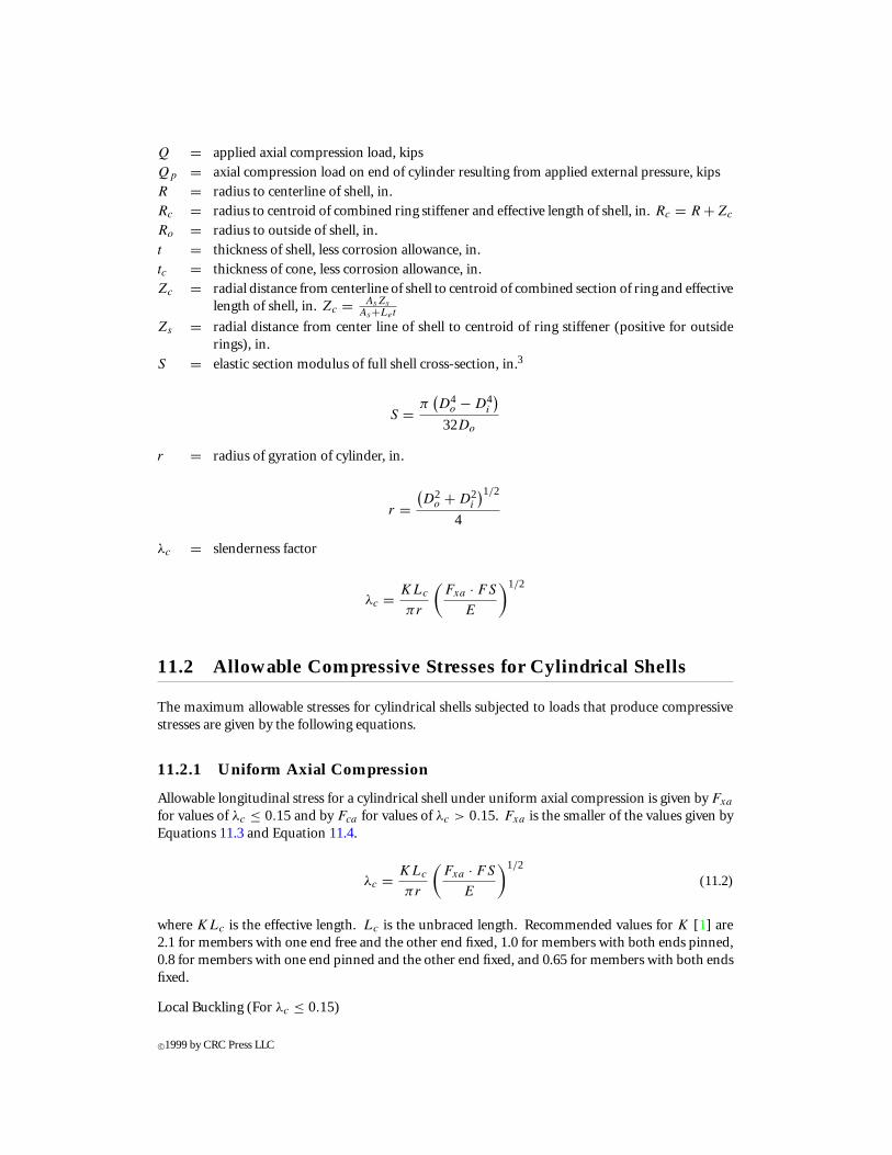
Q = applied axial compression load, kips
Qp = axial compression load on end of cylinder resulting from applied external pressure, kips
R = radius to centerline of shell, in.
Rc = radius to centroid of combined ring stiffener and effective length of shell, in. Rc = R +Zc
Ro = radius to outside of shell, in.
t = thickness of shell, less corrosion allowance, in.
tc = thickness of cone, less corrosion allowance, in.
Zc = radial distance from centerline of shell to centroid of combined section of ring and effectivelength of shell, in. Zc = AsZs
As+Let
Zs = radial distance from center line of shell to centroid of ring stiffener (positive for outsiderings), in.
S = elastic section modulus of full shell cross-section, in.3
S = π(D4
o − D4i
)32Do
r = radius of gyration of cylinder, in.
r =(D2
o + D2i
)1/2
4
λc = slenderness factor
λc = KLc
πr
(Fxa · FS
E
)1/2
11.2 Allowable Compressive Stresses for Cylindrical Shells
The maximum allowable stresses for cylindrical shells subjected to loads that produce compressivestresses are given by the following equations.
11.2.1 Uniform Axial Compression
Allowable longitudinal stress for a cylindrical shell under uniform axial compression is given by Fxa
for values of λc ≤ 0.15and by Fca for values of λc > 0.15. Fxa is the smaller of the values given byEquations 11.3 and Equation 11.4.
λc = KLc
πr
(Fxa · FS
E
)1/2
(11.2)
where KLc is the effective length. Lc is the unbraced length. Recommended values for K [1] are2.1 for members with one end free and the other end fixed, 1.0 for members with both ends pinned,0.8 for members with one end pinned and the other end fixed, and 0.65 for members with both endsfixed.
Local Buckling (For λc ≤ 0.15)
c©1999 by CRC Press LLC
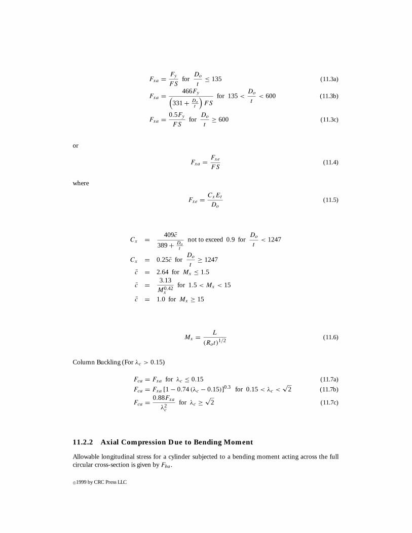
Fxa = Fy
FSfor
Do
t≤ 135 (11.3a)
Fxa = 466Fy(331+ Do
t
)FS
for 135<Do
t< 600 (11.3b)
Fxa = 0.5Fy
FSfor
Do
t≥ 600 (11.3c)
or
Fxa = Fxe
FS(11.4)
where
Fxe = CxEt
Do
(11.5)
Cx = 409c̄
389+ Do
t
not to exceed 0.9 forDo
t< 1247
Cx = 0.25c̄ forDo
t≥ 1247
c̄ = 2.64 for Mx ≤ 1.5
c̄ = 3.13
M0.42x
for 1.5 < Mx < 15
c̄ = 1.0 for Mx ≥ 15
Mx = L
(Rot)1/2
(11.6)
Column Buckling (For λc > 0.15)
Fca = Fxa for λc ≤ 0.15 (11.7a)
Fca = Fxa [1 − 0.74(λc − 0.15)]0.3 for 0.15 < λc <√
2 (11.7b)
Fca = 0.88Fxa
λ2c
for λc ≥ √2 (11.7c)
11.2.2 Axial Compression Due to Bending Moment
Allowable longitudinal stress for a cylinder subjected to a bending moment acting across the fullcircular cross-section is given by Fba .
c©1999 by CRC Press LLC
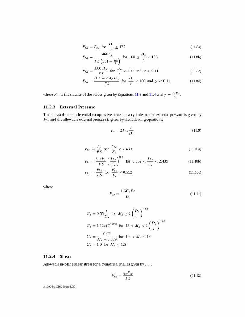
Fba = Fxa forDo
t≥ 135 (11.8a)
Fba = 466Fy
FS(331+ Do
t
) for 100≤ Do
t< 135 (11.8b)
Fba = 1.081Fy
FSfor
Do
t< 100 and γ ≥ 0.11 (11.8c)
Fba = (1.4 − 2.9γ )Fy
FSfor
Do
t< 100 and γ < 0.11 (11.8d)
where Fxa is the smaller of the values given by Equations 11.3 and 11.4 and γ = FyDo
Et.
11.2.3 External Pressure
The allowable circumferential compressive stress for a cylinder under external pressure is given byFha and the allowable external pressure is given by the following equations:
Pa = 2Fha
t
Do
(11.9)
Fha = Fy
FSfor
Fhe
Fy
≥ 2.439 (11.10a)
Fha = 0.7Fy
FS
(Fhe
Fy
)0.4
for 0.552<Fhe
Fy
< 2.439 (11.10b)
Fha = Fhe
FSfor
Fhe
Fy
≤ 0.552 (11.10c)
where
Fhe = 1.6ChEt
Do
(11.11)
Ch = 0.55t
Do
for Mx ≥ 2
(Do
t
)0.94
Ch = 1.12M−1.058x for 13 < Mx < 2
(Do
t
)0.94
Ch = 0.92
Mx − 0.579for 1.5 < Mx ≤ 13
Ch = 1.0 for Mx ≤ 1.5
11.2.4 Shear
Allowable in-plane shear stress for a cylindrical shell is given by Fva .
Fva = ηvFve
FS(11.12)
c©1999 by CRC Press LLC
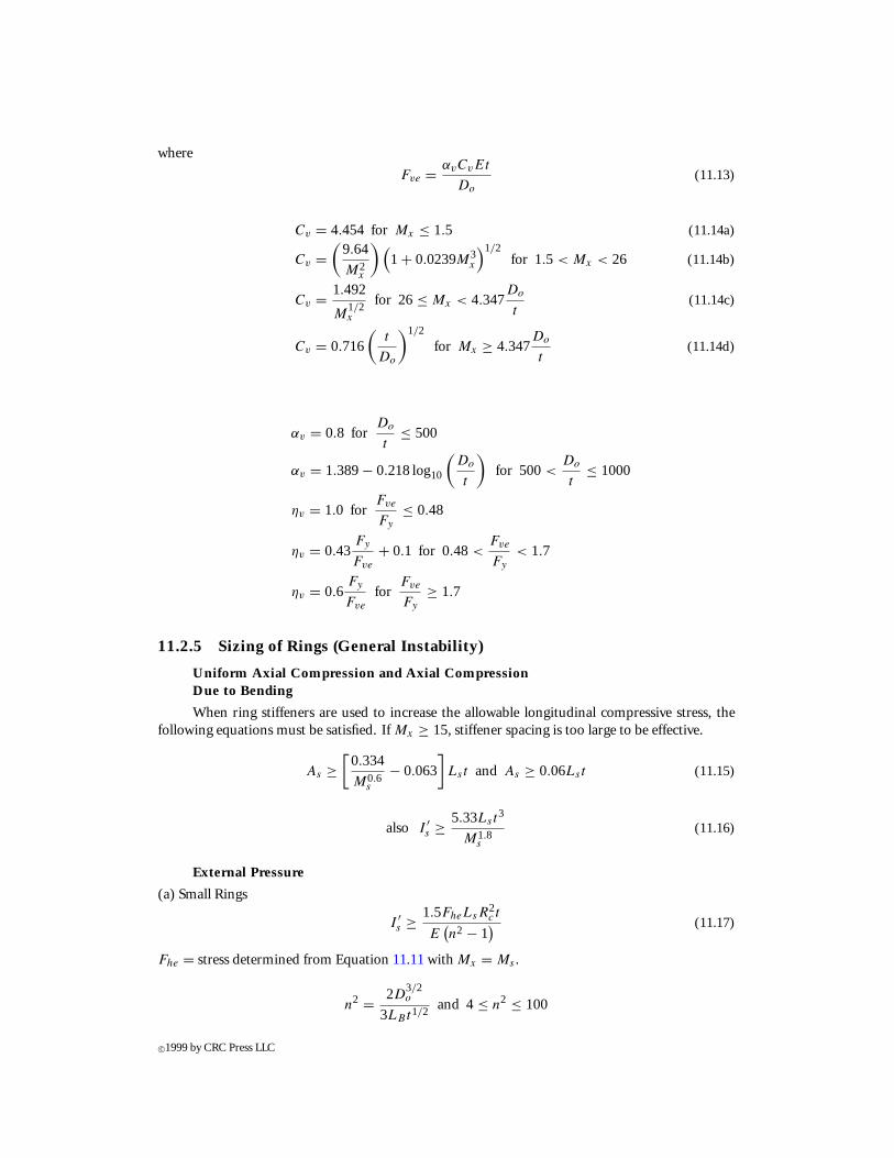
where
Fve = αvCvEt
Do
(11.13)
Cv = 4.454 for Mx ≤ 1.5 (11.14a)
Cv =(
9.64
M2x
)(1 + 0.0239M3
x
)1/2for 1.5 < Mx < 26 (11.14b)
Cv = 1.492
M1/2x
for 26 ≤ Mx < 4.347Do
t(11.14c)
Cv = 0.716
(t
Do
)1/2
for Mx ≥ 4.347Do
t(11.14d)
αv = 0.8 forDo
t≤ 500
αv = 1.389− 0.218 log10
(Do
t
)for 500<
Do
t≤ 1000
ηv = 1.0 forFve
Fy
≤ 0.48
ηv = 0.43Fy
Fve
+ 0.1 for 0.48 <Fve
Fy
< 1.7
ηv = 0.6Fy
Fve
forFve
Fy
≥ 1.7
11.2.5 Sizing of Rings (General Instability)
Uniform Axial Compression and Axial CompressionDue to Bending
When ring stiffeners are used to increase the allowable longitudinal compressive stress, thefollowing equations must be satisfied. If Mx ≥ 15, stiffener spacing is too large to be effective.
As ≥[
0.334
M0.6s
− 0.063
]Lst and As ≥ 0.06Lst (11.15)
also I ′s ≥ 5.33Lst
3
M1.8s
(11.16)
External Pressure
(a) Small Rings
I ′s ≥ 1.5FheLsR
2c t
E(n2 − 1
) (11.17)
Fhe = stress determined from Equation 11.11 with Mx = Ms .
n2 = 2D3/2o
3LBt1/2and 4 ≤ n2 ≤ 100
c©1999 by CRC Press LLC
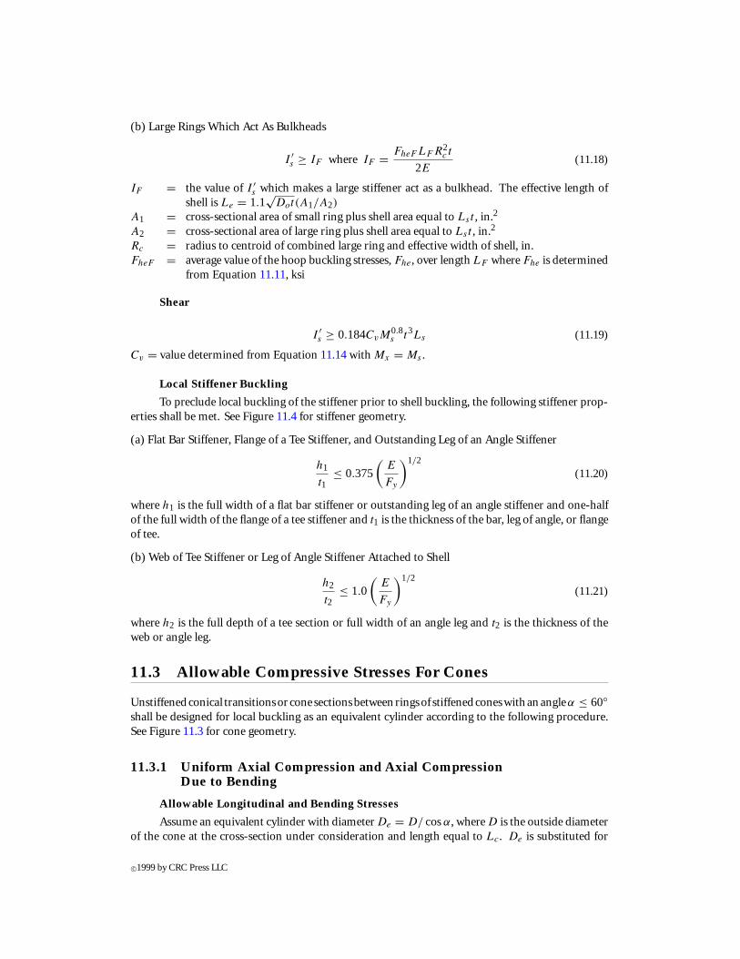
(b) Large Rings Which Act As Bulkheads
I ′s ≥ IF where IF = FheF LF R2
c t
2E(11.18)
IF = the value of I ′s which makes a large stiffener act as a bulkhead. The effective length of
shell is Le = 1.1√
Dot(A1/A2)
A1 = cross-sectional area of small ring plus shell area equal to Lst , in.2
A2 = cross-sectional area of large ring plus shell area equal to Lst , in.2
Rc = radius to centroid of combined large ring and effective width of shell, in.FheF = average value of the hoop buckling stresses, Fhe, over length LF where Fhe is determined
from Equation 11.11, ksi
Shear
I ′s ≥ 0.184CvM
0.8s t3Ls (11.19)
Cv = value determined from Equation 11.14 with Mx = Ms .
Local Stiffener Buckling
To preclude local buckling of the stiffener prior to shell buckling, the following stiffener prop-erties shall be met. See Figure 11.4 for stiffener geometry.
(a) Flat Bar Stiffener, Flange of a Tee Stiffener, and Outstanding Leg of an Angle Stiffener
h1
t1≤ 0.375
(E
Fy
)1/2
(11.20)
where h1 is the full width of a flat bar stiffener or outstanding leg of an angle stiffener and one-halfof the full width of the flange of a tee stiffener and t1 is the thickness of the bar, leg of angle, or flangeof tee.
(b) Web of Tee Stiffener or Leg of Angle Stiffener Attached to Shell
h2
t2≤ 1.0
(E
Fy
)1/2
(11.21)
where h2 is the full depth of a tee section or full width of an angle leg and t2 is the thickness of theweb or angle leg.
11.3 Allowable Compressive Stresses For Cones
Unstiffenedconical transitionsor cone sectionsbetweenringsof stiffenedconeswithanangleα ≤ 60◦shall be designed for local buckling as an equivalent cylinder according to the following procedure.See Figure 11.3 for cone geometry.
11.3.1 Uniform Axial Compression and Axial CompressionDue to Bending
Allowable Longitudinal and Bending Stresses
Assume an equivalent cylinder with diameter De = D/ cosα, where D is the outside diameterof the cone at the cross-section under consideration and length equal to Lc. De is substituted for
c©1999 by CRC Press LLC
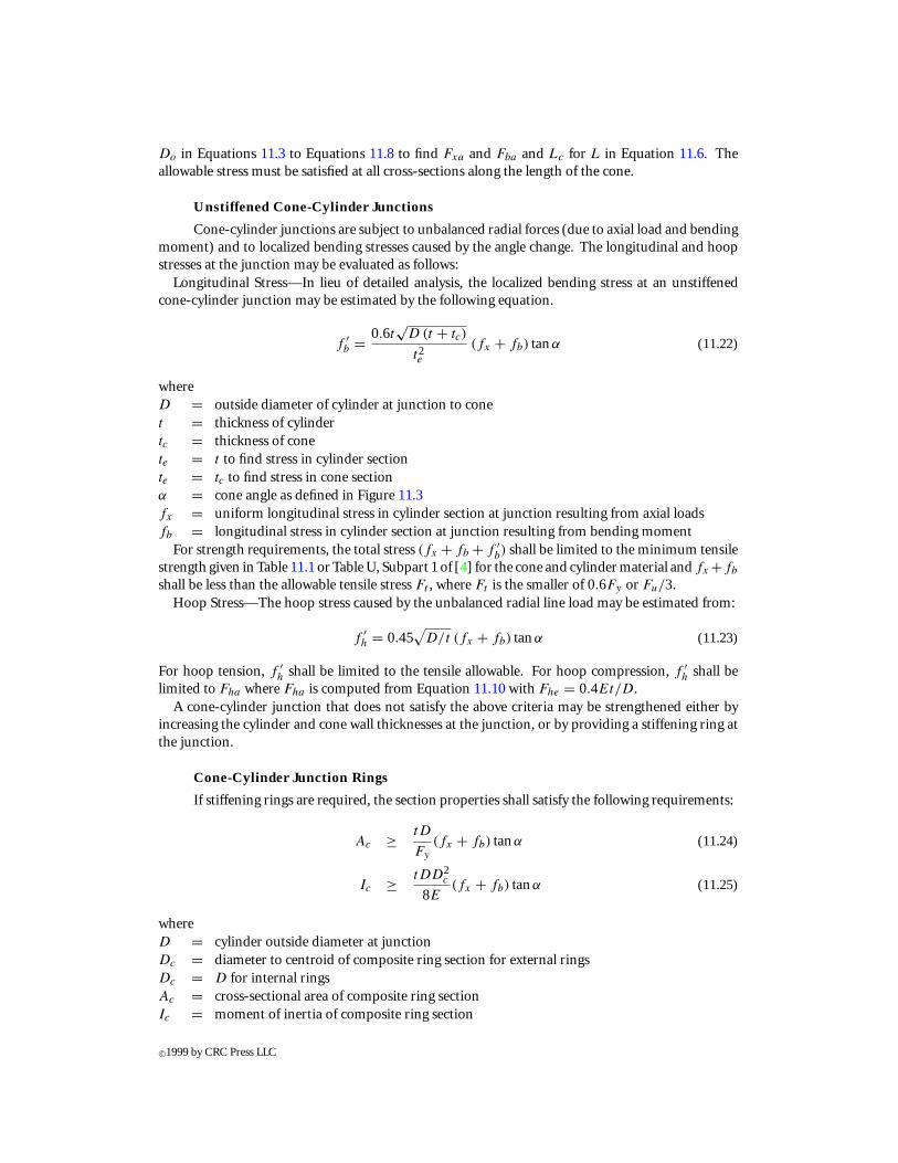
Do in Equations 11.3 to Equations 11.8 to find Fxa and Fba and Lc for L in Equation 11.6. Theallowable stress must be satisfied at all cross-sections along the length of the cone.
Unstiffened Cone-Cylinder Junctions
Cone-cylinder junctions are subject to unbalanced radial forces (due to axial load and bendingmoment) and to localized bending stresses caused by the angle change. The longitudinal and hoopstresses at the junction may be evaluated as follows:
Longitudinal Stress—In lieu of detailed analysis, the localized bending stress at an unstiffenedcone-cylinder junction may be estimated by the following equation.
f ′b = 0.6t
√D (t + tc)
t2e
(fx + fb) tanα (11.22)
whereD = outside diameter of cylinder at junction to conet = thickness of cylindertc = thickness of conete = t to find stress in cylinder sectionte = tc to find stress in cone sectionα = cone angle as defined in Figure 11.3fx = uniform longitudinal stress in cylinder section at junction resulting from axial loadsfb = longitudinal stress in cylinder section at junction resulting from bending moment
For strength requirements, the total stress (fx + fb + f ′b) shall be limited to the minimum tensile
strength given in Table 11.1 or Table U, Subpart 1 of [4] for the cone and cylinder material and fx +fb
shall be less than the allowable tensile stress Ft , where Ft is the smaller of 0.6Fy or Fu/3.Hoop Stress—The hoop stress caused by the unbalanced radial line load may be estimated from:
f ′h = 0.45
√D/t (fx + fb) tanα (11.23)
For hoop tension, f ′h shall be limited to the tensile allowable. For hoop compression, f ′
h shall belimited to Fha where Fha is computed from Equation 11.10 with Fhe = 0.4Et/D.
A cone-cylinder junction that does not satisfy the above criteria may be strengthened either byincreasing the cylinder and cone wall thicknesses at the junction, or by providing a stiffening ring atthe junction.
Cone-Cylinder Junction Rings
If stiffening rings are required, the section properties shall satisfy the following requirements:
Ac ≥ tD
Fy
(fx + fb) tanα (11.24)
Ic ≥ tDD2c
8E(fx + fb) tanα (11.25)
whereD = cylinder outside diameter at junctionDc = diameter to centroid of composite ring section for external ringsDc = D for internal ringsAc = cross-sectional area of composite ring sectionIc = moment of inertia of composite ring section
c©1999 by CRC Press LLC
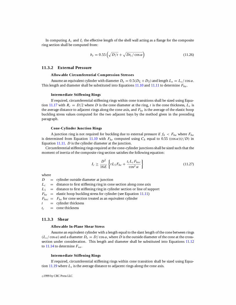
In computing Ac and Ic the effective length of the shell wall acting as a flange for the compositering section shall be computed from:
be = 0.55(√
D/t +√Dtc/ cosα
)(11.26)
11.3.2 External Pressure
Allowable Circumferential Compression Stresses
Assume an equivalent cylinder with diameter De = 0.5(DL +DS) and length Le = Lc/ cosα.This length and diameter shall be substituted into Equations 11.10 and 11.11 to determine Fha .
Intermediate Stiffening Rings
If required, circumferential stiffening rings within cone transitions shall be sized using Equa-tion 11.17 with Rc = D/2 where D is the cone diameter at the ring, t is the cone thickness, Ls isthe average distance to adjacent rings along the cone axis, and Fhe is the average of the elastic hoopbuckling stress values computed for the two adjacent bays by the method given in the precedingparagraph.
Cone-Cylinder Junction Rings
A junction ring is not required for buckling due to external pressure if fh < Fha where Fha
is determined from Equation 11.10 with Fhe computed using Ch equal to 0.55 (cosα)(t/D) inEquation 11.11. D is the cylinder diameter at the junction.
Circumferential stiffening rings required at the cone-cylinder junctions shall be sized such that themoment of inertia of the composite ring section satisfies the following equation:
Ic ≥ D2
16E
{tL1Fhe + tcLcFhec
cos2 α
}(11.27)
whereD = cylinder outside diameter at junctionLc = distance to first stiffening ring in cone section along cone axisL1 = distance to first stiffening ring in cylinder section or line of supportFhe = elastic hoop buckling stress for cylinder (see Equation 11.11)Fhec = Fhe for cone section treated as an equivalent cylindert = cylinder thicknesstc = cone thickness
11.3.3 Shear
Allowable In-Plane Shear Stress
Assume an equivalent cylinder with a length equal to the slant length of the cone between rings(Lc/ cosα) and a diameter De = D/ cosα, where D is the outside diameter of the cone at the cross-section under consideration. This length and diameter shall be substituted into Equations 11.12to 11.14 to determine Fva .
Intermediate Stiffening Rings
If required, circumferential stiffening rings within cone transition shall be sized using Equa-tion 11.19 where Ls is the average distance to adjacent rings along the cone axis.
c©1999 by CRC Press LLC
11.3.4 Local Stiffener Buckling
To preclude local buckling of a stiffener, the requirements of Equations 11.20 and 11.21 must be met.
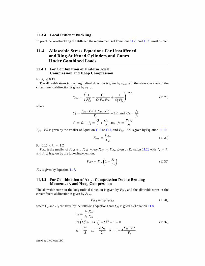
11.4 Allowable Stress Equations For Unstiffenedand Ring-Stiffened Cylinders and ConesUnder Combined Loads
11.4.1 For Combination of Uniform AxialCompression and Hoop Compression
For λc ≤ 0.15The allowable stress in the longitudinal direction is given by Fxha and the allowable stress in the
circumferential direction is given by Fhxa .
Fxha =(
1
F 2xa
− C1
C2FxaFha
+ 1
C22F 2
ha
)−0.5
(11.28)
where
C1 = Fxa · FS + Fha · FS
Fy
− 1.0 and C2 = fx
fh
fx = fa + fq = Q
A+ Qp
Aand fh = PDo
2t
Fxa · FS is given by the smaller of Equation 11.3 or 11.4, and Fha · FS is given by Equation 11.10.
Fhxa = Fxha
C2(11.29)
For 0.15 < λc < 1.2Fxha is the smaller of Fah1 and Fah2 where Fah1 = Fxha given by Equation 11.28 with fx = fa
and Fah2 is given by the following equation.
Fah2 = Fca
(1 − fq
Fy
)(11.30)
Fca is given by Equation 11.7.
11.4.2 For Combination of Axial Compression Due to BendingMoment, M, and Hoop Compression
The allowable stress in the longitudinal direction is given by Fbha and the allowable stress in thecircumferential direction is given by Fhba .
Fbha = C3C4Fba (11.31)
where C3 and C4 are given by the following equations and Fba is given by Equation 11.8.
C4 = fb
fh
Fha
Fba
C23
(C2
4 + 0.6C4
)+ C2n
3 − 1 = 0 (11.32)
fb = M
Sfh = PDo
2tn = 5 − 4
Fha · FS
Fy
c©1999 by CRC Press LLC
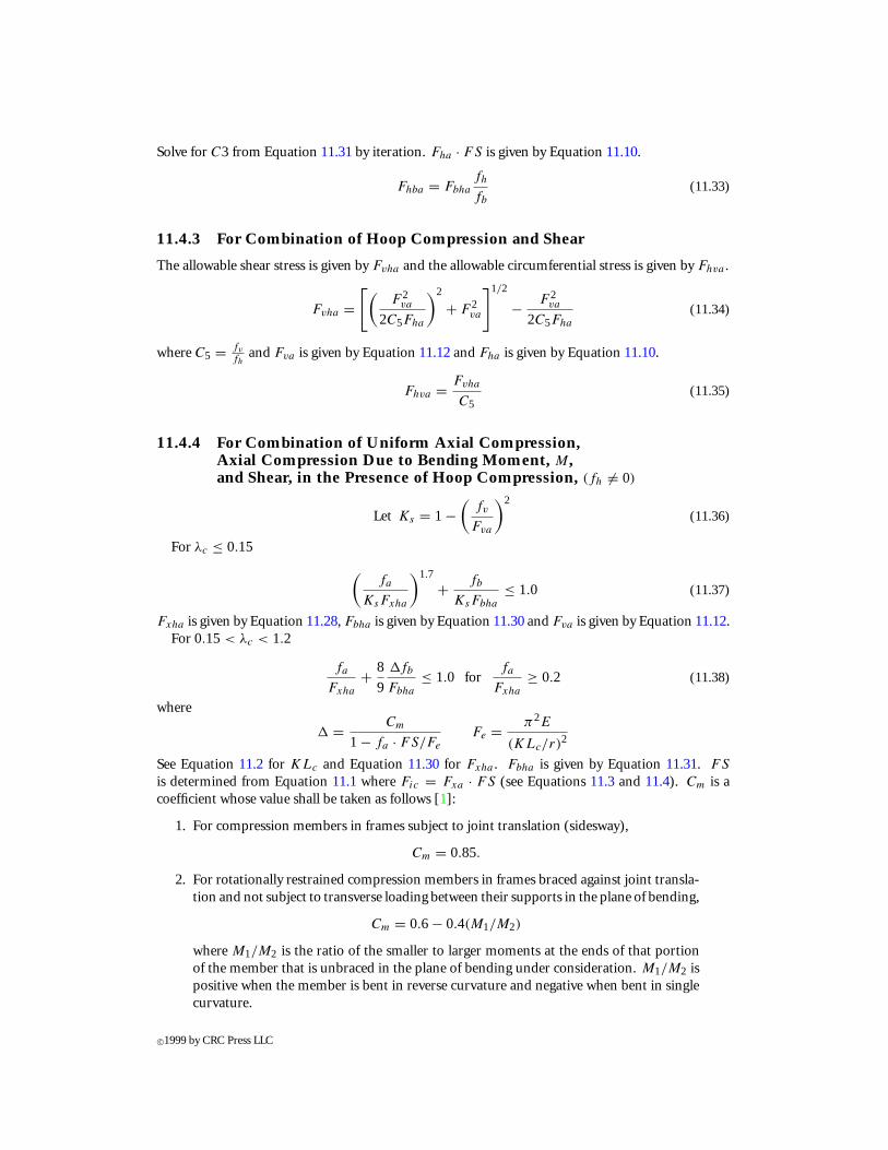
Solve for C3 from Equation 11.31 by iteration. Fha · FS is given by Equation 11.10.
Fhba = Fbha
fh
fb
(11.33)
11.4.3 For Combination of Hoop Compression and Shear
The allowable shear stress is given by Fvha and the allowable circumferential stress is given by Fhva .
Fvha =[(
F 2va
2C5Fha
)2
+ F 2va
]1/2
− F 2va
2C5Fha
(11.34)
where C5 = fv
fhand Fva is given by Equation 11.12 and Fha is given by Equation 11.10.
Fhva = Fvha
C5(11.35)
11.4.4 For Combination of Uniform Axial Compression,Axial Compression Due to Bending Moment, M,and Shear, in the Presence of Hoop Compression, (fh 6= 0)
Let Ks = 1 −(
fv
Fva
)2
(11.36)
For λc ≤ 0.15
(fa
KsFxha
)1.7
+ fb
KsFbha
≤ 1.0 (11.37)
Fxha is given by Equation 11.28, Fbha is given by Equation 11.30 and Fva is given by Equation 11.12.For 0.15 < λc < 1.2
fa
Fxha
+ 8
9
1fb
Fbha
≤ 1.0 forfa
Fxha
≥ 0.2 (11.38)
where
1 = Cm
1 − fa · FS/Fe
Fe = π2E
(KLc/r)2
See Equation 11.2 for KLc and Equation 11.30 for Fxha . Fbha is given by Equation 11.31. FS
is determined from Equation 11.1 where Fic = Fxa · FS (see Equations 11.3 and 11.4). Cm is acoefficient whose value shall be taken as follows [1]:
1. For compression members in frames subject to joint translation (sidesway),
Cm = 0.85.
2. For rotationally restrained compression members in frames braced against joint transla-tion and not subject to transverse loading between their supports in the plane of bending,
Cm = 0.6 − 0.4(M1/M2)
where M1/M2 is the ratio of the smaller to larger moments at the ends of that portionof the member that is unbraced in the plane of bending under consideration. M1/M2 ispositive when the member is bent in reverse curvature and negative when bent in singlecurvature.
c©1999 by CRC Press LLC
3. For compression members in frames braced against joint translation and subjected totransverse loading between their supports the following apply:
a. for members whose ends are restrained against rotation in the plane of bending,
Cm = 0.85
b. formemberswhose endsareunrestrainedagainst rotation in theplaneofbending,
Cm = 1.0
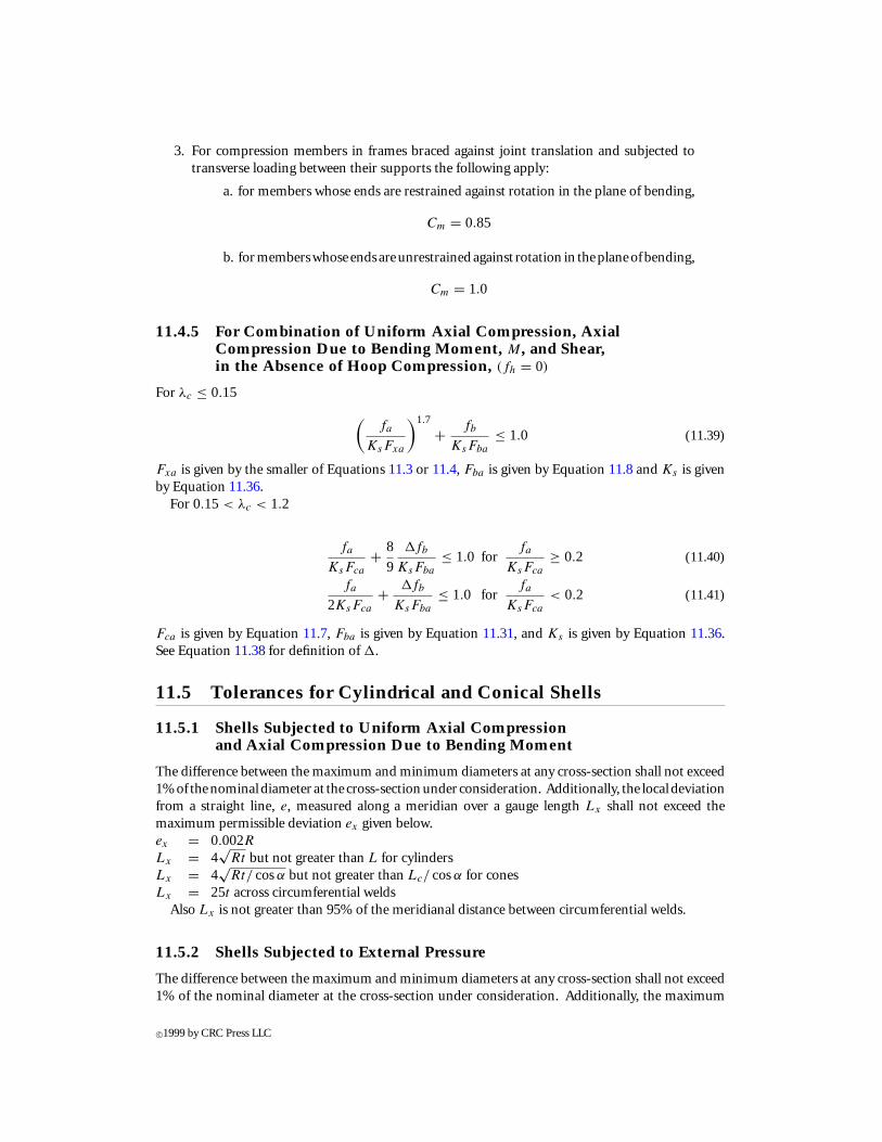
11.4.5 For Combination of Uniform Axial Compression, AxialCompression Due to Bending Moment, M, and Shear,in the Absence of Hoop Compression, (fh = 0)
For λc ≤ 0.15
(fa
KsFxa
)1.7
+ fb
KsFba
≤ 1.0 (11.39)
Fxa is given by the smaller of Equations 11.3 or 11.4, Fba is given by Equation 11.8 and Ks is givenby Equation 11.36.
For 0.15 < λc < 1.2
fa
KsFca
+ 8
9
1fb
KsFba
≤ 1.0 forfa
KsFca
≥ 0.2 (11.40)
fa
2KsFca
+ 1fb
KsFba
≤ 1.0 forfa
KsFca
< 0.2 (11.41)
Fca is given by Equation 11.7, Fba is given by Equation 11.31, and Ks is given by Equation 11.36.See Equation 11.38 for definition of 1.
11.5 Tolerances for Cylindrical and Conical Shells
11.5.1 Shells Subjected to Uniform Axial Compressionand Axial Compression Due to Bending Moment
The difference between the maximum and minimum diameters at any cross-section shall not exceed1%of thenominaldiameter at the cross-sectionunder consideration. Additionally, the localdeviationfrom a straight line, e, measured along a meridian over a gauge length Lx shall not exceed themaximum permissible deviation ex given below.ex = 0.002RLx = 4
√Rt but not greater than L for cylinders
Lx = 4√
Rt/ cosα but not greater than Lc/ cosα for conesLx = 25t across circumferential welds
Also Lx is not greater than 95% of the meridianal distance between circumferential welds.
11.5.2 Shells Subjected to External Pressure
The difference between the maximum and minimum diameters at any cross-section shall not exceed1% of the nominal diameter at the cross-section under consideration. Additionally, the maximum
c©1999 by CRC Press LLC
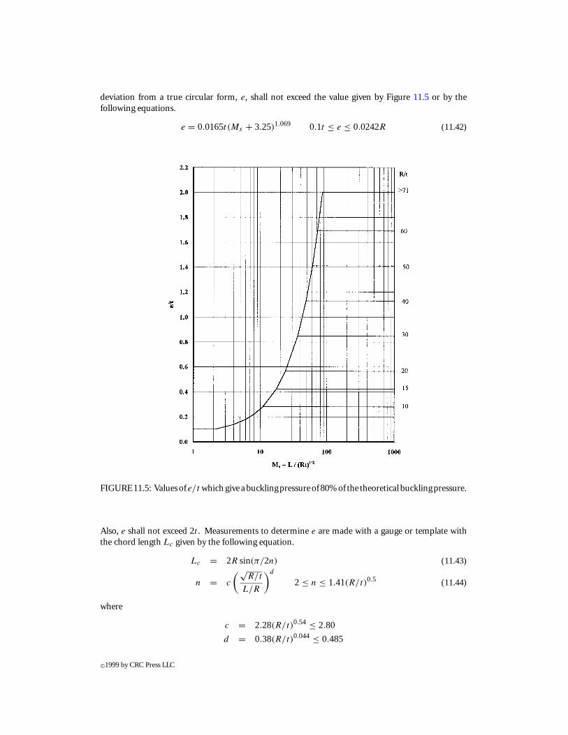
deviation from a true circular form, e, shall not exceed the value given by Figure 11.5 or by thefollowing equations.
e = 0.0165t (Mx + 3.25)1.069 0.1t ≤ e ≤ 0.0242R (11.42)
FIGURE11.5: Valuesof e/t whichgive abucklingpressureof 80%of the theoretical bucklingpressure.
Also, e shall not exceed 2t . Measurements to determine e are made with a gauge or template withthe chord length Lc given by the following equation.
Lc = 2R sin(π/2n) (11.43)
n = c
(√R/t
L/R
)d
2 ≤ n ≤ 1.41(R/t)0.5 (11.44)
where
c = 2.28(R/t)0.54 ≤ 2.80
d = 0.38(R/t)0.044 ≤ 0.485
c©1999 by CRC Press LLC
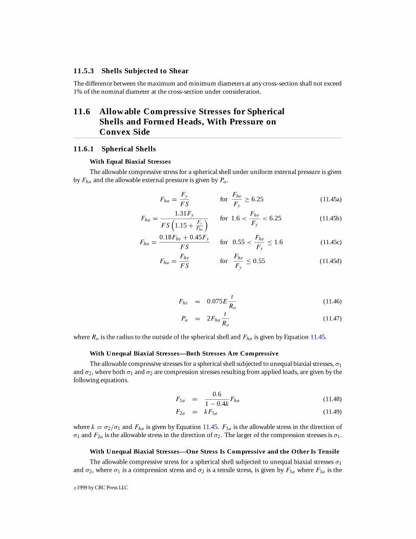
11.5.3 Shells Subjected to Shear
The difference between the maximum and minimum diameters at any cross-section shall not exceed1% of the nominal diameter at the cross-section under consideration.
11.6 Allowable Compressive Stresses for SphericalShells and Formed Heads, With Pressure onConvex Side
11.6.1 Spherical Shells
With Equal Biaxial Stresses
The allowable compressive stress for a spherical shell under uniform external pressure is givenby Fha and the allowable external pressure is given by Pa .
Fha = Fy
FSfor
Fhe
Fy
≥ 6.25 (11.45a)
Fha = 1.31Fy
FS(1.15+ Fy
Fhe
) for 1.6 <Fhe
Fy
< 6.25 (11.45b)
Fha = 0.18Fhe + 0.45Fy
FSfor 0.55 <
Fhe
Fy
≤ 1.6 (11.45c)
Fha = Fhe
FSfor
Fhe
Fy
≤ 0.55 (11.45d)
Fhe = 0.075Et
Ro
(11.46)
Pa = 2Fha
t
Ro
(11.47)
where Ro is the radius to the outside of the spherical shell and Fha is given by Equation 11.45.
With Unequal Biaxial Stresses—Both Stresses Are Compressive
The allowable compressive stresses for a spherical shell subjected to unequal biaxial stresses, σ1and σ2, where both σ1 and σ2 are compression stresses resulting from applied loads, are given by thefollowing equations.
F1a = 0.6
1 − 0.4kFha (11.48)
F2a = kF1a (11.49)
where k = σ2/σ1 and Fha is given by Equation 11.45. F1a is the allowable stress in the direction ofσ1 and F2a is the allowable stress in the direction of σ2. The larger of the compression stresses is σ1.
With Unequal Biaxial Stresses—One Stress Is Compressive and the Other Is Tensile
The allowable compressive stress for a spherical shell subjected to unequal biaxial stresses σ1and σ2, where σ1 is a compression stress and σ2 is a tensile stress, is given by F1a where F1a is the
c©1999 by CRC Press LLC

value of Fha determined from Equation 11.45 with Fhe given by Equation 11.50.
Fhe = (Co + Cp
)E
t
Ro
(11.50)
Co = 102.2
195+ Ro/tfor
Ro
t< 622
Co = 0.125 forRo
t≥ 622
Cp = 1.06
3.24+ 1p̄
p̄ = σ2
E
Ro
t
Shear
When shear is present, the principal stresses shall be calculated and used for σ1 and σ2.
11.6.2 Toroidal and Ellipsoidal Heads
Theallowable compressive stresses for formedheads is determinedby the equations given for sphericalshells where Ro is defined below.
Ro = the outside radius of the crown portion of the head for torispherical heads, in.
Ro = the equivalent outside spherical radius taken as KoDo for ellipsoidal heads, in.
Ko = factor depending on the ellipsoidal head proportions Do/2ho (see Table 11.2)
ho = outside height of the ellipsoidal head measured from the tangent line (head-bend line), in.
TABLE 11.2 Factor Ko
Do/2ho . . . 3.0 2.8 2.6 2.4 2.2Ko . . . 1.36 1.27 1.18 1.08 0.99
Do/2ho 2.0 1.8 1.6 1.4 1.2 1.0Ko 0.90 0.81 0.73 0.65 0.57 0.50
Note: Use interpolation for intermediate values.
11.7 Tolerances for Formed Heads
The inner surface of a spherical shell or formed head shall not deviate from the specified shape morethan 1.25% of the nominal diameter of the vessel. Such deviations shall be measured perpendicularto the specified shape. Additionally, the maximum local deviation from a true circular form, e, forspherical shells and any spherical portion of a formed head designed for external pressure shall notexceed the shell thickness. Measurements to determine e are made with a gauge or template with thechord length Lc given by the following equation:
Lc = 3.72√
Rt
c©1999 by CRC Press LLC
References
[1] AISC. 1989. Manual of Steel Construction, Allowable Stress Design, 9th ed., Section C-C2,American Institute of Steel Construction, Chicago, IL.
[2] API 2U. 1987. API Bulletin 2U, “Bulletin on Stability Design of Cylindrical Shells,” 1st ed.,American Petroleum Institute, Washington, D.C.
[3] ASME. 1992. ASME Boiler and Pressure Vessel Code, Section VIII, Rules for Construction ofPressure Vessels, Division 1, American Society of Mechanical Engineers, New York.
[4] ASME. 1992. ASME Boiler and Pressure Vessel Code, Section II, Materials, Part D-Properties,American Society of Mechanical Engineers, New York.
[5] AWS. 1992, Structural Welding Code, AWS D1.1-92, American Welding Society.[6] Miller, C.D. 1982. “Experimental Study of the Buckling of Cylindrical Shells With Reinforced
Openings,” ASME/ANS Nuclear Engineering Conference, Portland, OR.[7] Miller, C.D. 1991. “ASME Code Case N-284: Metal Containment Shell Buckling Design Meth-
ods,” Revision 1, in Code Cases: Nuclear Components, ASME Boiler and Pressure Vessel Code,American Society of Mechanical Engineers, New York, March 14, 1995.
[8] Miller, C.D. 1995. An Evaluation of Codes and Standards Related to Buckling of CylindricalShells Subjected to Axial Compression, Bending and External Pressure, UMI DissertationServices, Ann Arbor, MI.
[9] Miller, C.D. and Saliklis, E.P. 1993. “Analysis of Cylindrical Shell Database and Validationof Design Formulations,” API Project 90-56, Chicago Bridge & Iron Technical Services Co.,Plainfield, IL.
[10] Miller, C.D. and Saliklis, E.P. 1995. “Analysis of Cylindrical Shell Database and Validation ofDesign Formulations, Phase 2: For D/t Values > 300,” API Project 92-56, Chicago Bridge &Iron Technical Services Co., Plainfield, IL.
Further Reading
Additional information on the design of shell structures can be found in the following references:
[1] American Iron and Steel Institute, 1992. Steel Plate Engineering Data, Volume 1—Steel Tanksfor Liquid Storage and Volume 2—Useful Information on the Design of Plate Structures.
[2] Wozniak, R.S. 1990. Steel Tanks, in Structural Engineering Handbook, Gaylord, E.H. andGaylord, C.S. Eds., 3rd ed., McGraw-Hill, New York, 27-1 to 27-29.
The following is a list of codes, specifications, and standards that provide rules for the design of shellstructures subject to instability from loads which produce compressive stresses in the shell elements.A comparison was made by Miller and Saliklis [8, 9, 10] of the predicted failure stresses given by eachof these sets of rules with the test data obtained from over 600 tests on steel models representative offabricated shells. The best fit equations were determined for each shell type and load. These equationswere then modified to obtain a better fit with the test database. The equations given in this chapterare the results of these studies.
[3] API BUL 2U. 1987. Bulletin on Stability Design of Cylindrical Shells, 1st ed., AmericanPetroleum Institute, Washington, D.C.
[4] API RP 2A-LRFD. 1993. Recommended Practice for Planning, Designing and ConstructingFixed Offshore Platforms—Load and Resistance Factor Design, 1st ed., American PetroleumInstitute, Washington, D.C.
[5] API RP 2A-WSD. 1993. Recommended Practice for Planning, Designing and ConstructingFixed Offshore Platforms—Working Stress Design, 20th ed., American Petroleum Institute,Washington, D.C.
c©1999 by CRC Press LLC
[6] API STD 620. 1990. Design and Construction of Large, Welded Low-Pressure Storage Tanks,8th ed., American Petroleum Institute, Washington, D.C.
[7] API STD 650. 1993. Welded Steel Tanks for Oil Storage, 9th ed., American Petroleum Institute,Washington, D.C.
[8] ASME VIII. 1992. Pressure Vessels, Division 2, ASME Boiler and Pressure Code, AmericanSociety of Mechanical Engineers, Washington, D.C.
[9] AWWA D100. 1984. AWWA Standard for Welded Steel Tanks for Water Storage, AmericanWater Works Association, Denver, CO.
[10] DIN 18800. 1990. Stability of Shell Type Steel Structures, German Code DIN 18800, Part 4.[11] ECCS No. 56. 1988. Buckling of Steel Shells, European Recommendations, European Conven-
tion for Constructional Steelwork, Publication No. 56, 4th ed., Brussels, Belgium.[12] NPD. 1990. Buckling Criteria for Cylindrical Shells, Norwegian Petroleum Directorate, Oslo,
Norway.
c©1999 by CRC Press LLC