Recommended Practices for Dimensions, Dimensional and Geometric … · Guide for Geometric...
45
Recommended Practices for Dimensions, Dimensional and Geometric Tolerances December 6, 2006 Contacts: David Briggs Steve Yates Boeing Information Technology Theorem Solutions Ltd. P.O. Box 3707 M/S 2R-97 Tame House Seattle, WA 98124 USA Fradley Park [email protected] Staffordshire United Kingdom WS13 8RZ Tom Hendrix [email protected] Boeing Information Technology P.O. Box 3707 M/S 2R-97 Seattle, WA 98124 USA [email protected]
Transcript of Recommended Practices for Dimensions, Dimensional and Geometric … · Guide for Geometric...
Recommended Practices forDimensions, Dimensional and Geometric
TolerancesDecember 6, 2006
Contacts:
David Briggs Steve YatesBoeing Information Technology Theorem Solutions Ltd.P.O. Box 3707 M/S 2R-97 Tame HouseSeattle, WA 98124 USA Fradley [email protected] Staffordshire
United Kingdom WS13 8RZTom Hendrix [email protected] Information TechnologyP.O. Box 3707 M/S 2R-97Seattle, WA 98124 [email protected]
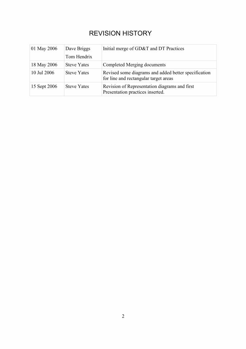
REVISION HISTORY
01 May 2006 Dave Briggs
Tom Hendrix
Initial merge of GD&T and DT Practices
18 May 2006 Steve Yates Completed Merging documents10 Jul 2006 Steve Yates Revised some diagrams and added better specification
for line and rectangular target areas15 Sept 2006 Steve Yates Revision of Representation diagrams and first
Presentation practices inserted.
2
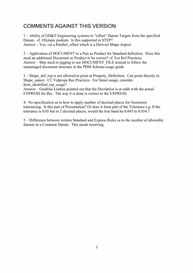
COMMENTS AGAINST THIS VERSION
1 – Ability of GD&T Engineering systems to “offset” Datum Targets from the specifiedDatum. cf. Olympic podium. Is this supported in STEP?Answer – Yes, via a Parallel_offset which is a Derived Shape Aspect.
2 – Application of DOCUMENT to a Part as Product for Standard definition. Does thisneed an additional Document as Product to be correct? cf. Ext Ref Practices.Answer – May need re-jigging to use DOCUMENT_FILE instead to follow theunmanaged document structure in the PDM Schema usage guide
3 – Shape_def_rep is not allowed to point at Property_Definition. Can point directly toShape_aspect. Cf. Valprops Rec.Practices. For future usage, considerItem_identified_rep_usage?Answer – Giedrius Liutkus pointed out that the Decription is at odds with the actualEXPRESS for this. The way it is done is correct to the EXPRESS.
4– No specification as to how to apply number of decimal places for Geometrictolerancing. Is this part of Presentation? Or does it form part of the Tolerance e.g. If thetolerance is 0.05 but to 2 decimal places, would the true band be 0.045 to 0.054 ?
5 – Difference between written Standard and Express Rules as to the number of allowabledatums in a Common Datum. This needs resolving.
3
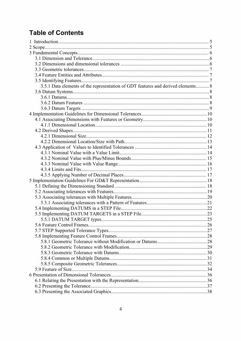
Table of Contents1 Introduction............................................................................................................................ 52 Scope....................................................................................................................................... 53 Fundamental Concepts............................................................................................................ 6
3.1 Dimension and Tolerance................................................................................................ 63.2 Dimensions and dimensional tolerances .........................................................................63.3 Geometric tolerances....................................................................................................... 73.4 Feature Entities and Attributes........................................................................................ 73.5 Identifying Features......................................................................................................... 7
3.5.1 Data elements of the representation of GDT features and derived elements........... 83.6 Datum Systems................................................................................................................ 8
3.6.1 Datums..................................................................................................................... 83.6.2 Datum Features ....................................................................................................... 83.6.3 Datum Targets .........................................................................................................9
4 Implementation Guidelines for Dimensional Tolerances......................................................104.1 Associating Dimensions with Features or Geometry.....................................................10
4.1.1 Dimensional Location............................................................................................ 104.2 Derived Shapes.............................................................................................................. 11
4.2.1 Dimensional Size................................................................................................... 124.2.2 Dimensional Location/Size with Path....................................................................13
4.3 Application of Values to Identified Tolerances ...........................................................144.3.1 Nominal Value with a Value Limit........................................................................144.3.2 Nominal Value with Plus/Minus Bounds.............................................................. 154.3.3 Nominal Value with Value Range......................................................................... 164.3.4 Limits and Fits....................................................................................................... 174.3.5 Applying Number of Decimal Places.................................................................... 17
5 Implementation Guidelines For GD&T Representation........................................................185.1 Defining the Dimensioning Standard ........................................................................... 185.2 Associating tolerances with Features.............................................................................195.3 Associating tolerances with Multiple Features..............................................................20
5.3.1 Associating tolerances with a Pattern of Features..................................................215.4 Implementing DATUMS in a STEP File.......................................................................225.5 Implementing DATUM TARGETS in a STEP File......................................................23
5.5.1 DATUM TARGET types.......................................................................................255.6 Feature Control Frames................................................................................................. 265.7 STEP Supported Tolerance Types.................................................................................275.8 Implementing Feature Control Frames.......................................................................... 28
5.8.1 Geometric Tolerance without Modification or Datums.........................................285.8.2 Geometric Tolerance with Modification................................................................295.8.3 Geometric Tolerance with Datums........................................................................ 305.8.4 Common or Multiple Datums................................................................................ 315.8.5 Composite Geometric Tolerances..........................................................................32
5.9 Feature of Size............................................................................................................... 346 Presentation of Dimensional Tolerances............................................................................... 36
6.1 Relating the Presentation with the Representation........................................................ 366.2 Presenting the Tolerance................................................................................................376.3 Presenting the Associated Graphics...............................................................................38
4
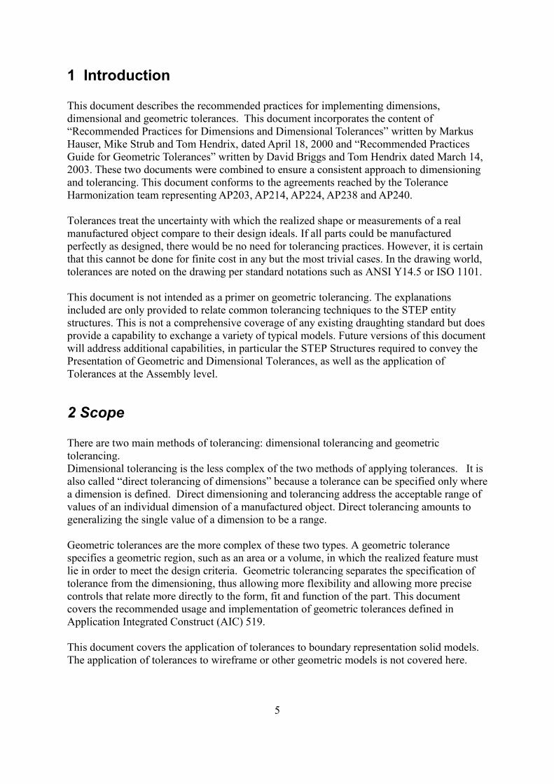
1 Introduction
This document describes the recommended practices for implementing dimensions,dimensional and geometric tolerances. This document incorporates the content of“Recommended Practices for Dimensions and Dimensional Tolerances” written by MarkusHauser, Mike Strub and Tom Hendrix, dated April 18, 2000 and “Recommended PracticesGuide for Geometric Tolerances” written by David Briggs and Tom Hendrix dated March 14,2003. These two documents were combined to ensure a consistent approach to dimensioningand tolerancing. This document conforms to the agreements reached by the ToleranceHarmonization team representing AP203, AP214, AP224, AP238 and AP240.
Tolerances treat the uncertainty with which the realized shape or measurements of a realmanufactured object compare to their design ideals. If all parts could be manufacturedperfectly as designed, there would be no need for tolerancing practices. However, it is certainthat this cannot be done for finite cost in any but the most trivial cases. In the drawing world,tolerances are noted on the drawing per standard notations such as ANSI Y14.5 or ISO 1101.
This document is not intended as a primer on geometric tolerancing. The explanationsincluded are only provided to relate common tolerancing techniques to the STEP entitystructures. This is not a comprehensive coverage of any existing draughting standard but doesprovide a capability to exchange a variety of typical models. Future versions of this documentwill address additional capabilities, in particular the STEP Structures required to convey thePresentation of Geometric and Dimensional Tolerances, as well as the application ofTolerances at the Assembly level.
2 Scope
There are two main methods of tolerancing: dimensional tolerancing and geometrictolerancing. Dimensional tolerancing is the less complex of the two methods of applying tolerances. It isalso called “direct tolerancing of dimensions” because a tolerance can be specified only wherea dimension is defined. Direct dimensioning and tolerancing address the acceptable range ofvalues of an individual dimension of a manufactured object. Direct tolerancing amounts togeneralizing the single value of a dimension to be a range.
Geometric tolerances are the more complex of these two types. A geometric tolerancespecifies a geometric region, such as an area or a volume, in which the realized feature mustlie in order to meet the design criteria. Geometric tolerancing separates the specification oftolerance from the dimensioning, thus allowing more flexibility and allowing more precisecontrols that relate more directly to the form, fit and function of the part. This documentcovers the recommended usage and implementation of geometric tolerances defined inApplication Integrated Construct (AIC) 519.
This document covers the application of tolerances to boundary representation solid models.The application of tolerances to wireframe or other geometric models is not covered here.
5
3 Fundamental Concepts
A tolerance describes a constraint on the acceptable deviation of a manufactured object fromthe ideal design. Tolerances are applied to the geometric aspects or features of a part, such asedges, faces and holes.
The fundamental principles of geometric tolerances can be found in national and internationalstandards such as ANSI Y14.5M-1994 or ISO 5459-1981.
There are several subtypes of the geometric_tolerance entity, which are not mutuallyexclusive. For example, tolerances that reference datums are of typegeometric_tolerance_with_datum_reference. Tolerances that include a modifier such asmaximum material condition are of type modified_geometric_tolerance. Many typicalengineering tolerances combine these. In these cases, complex entities instances will occur inthe Part 21 file.
3.1 Dimension and Tolerance
Dimension is a term for a specification of the value of a parameter of some aspect of theshape of a mechanical part or assembly. A dimension can be implied by the geometricmodel, or it can be explicitly modeled, which is what this guide covers. The term dimensioncan also refer to the numerical value itself; however in this document the term value is used. Tolerance is a general term for permitted variations in the shape of manufactured parts.Tolerance treats the how the realized form or measurements of a real manufactured objectcompare to their design ideals.
3.2 Dimensions and dimensional tolerances The dimensions and dimensional tolerances addressed in this document are:
• directional dimensions
• location dimensions such as angular, curved, or linear distances
• size dimensions such as angular, thickness, or other
• the association of dimensions with geometry
• the representation of dimensional tolerances including:
• plus-or-minus deviations
• maxima, minima, and nominal dimensions
• limits and fits
• significant digits
• the association of dimensional tolerances with dimensions
6
3.3 Geometric tolerancesThe geometric tolerances addressed in this document are:
AngularityCircular runoutCircularity/RoundnessCoaxiality/ConcentricityCylindricityFlatnessParallelismPerpendicularityPositionProfile of a lineProfile of a surfaceStraightnessSymmetryTotal runout
Tolerance modifiers (Maximum and minimum material condition, regardless of feature sizeand projected tolerance zone) are also addressed.
3.4 Feature Entities and AttributesDimensions and dimensional tolerances are applied to aspects of the product shape. Theproduct and product shape are modeled as in other geometry and PDM applications.
GDT Features in STEP are modeled as shape_aspects. The term “feature” in somedimensioning standards is reserved for definitional elements that lie in the surface of the part.In such cases, a term such as “derived element”, is used for derived geometry. In computingsystems and in some dimensioning standards, either is called a feature, and these aredistinguished as “integral” feature and “derived” feature. In this recommendation, all aremodeled as shape aspect. For integral features, shape_aspects.product_definitional=”.TRUE.”For derived elements it is shape_aspects.product_definitional=”.FALSE.”
3.5 Identifying FeaturesThe surface of a part can be partitioned into features, which to which dimensions are applied.Normally a feature boundary corresponds to a locus of discontinuities of surface curvature, aswhen a straight side encounters a corner fillet. For the purposes of GDT, every point on thesurface is either in the interior of one feature or on the boundary of two or more features.When a finished part is measured, each point of the surface belongs to exactly one feature.
It is sometimes convenient to treat as a single feature a union of these natural geometricfeatures. Unions can be disjoint, for example:
• a pattern of holes
• a surface that is “interrupted” by a slot.
• the two sides of a slot
7
Unions can be made of contiguous features for example:
• the all-around shape of an irregular hole.
Similarly its may be necessary to identify a restricted region of a feature, for example:
• Where a tighter tolerance is required
• to indicate how a finished piece is mounted on a inspection workbench.
.
3.5.1 Data elements of the representation of GDT featuresand derived elements.It is recommended that when available the advanced_face be used for representing a feature,since its topology is well-defined. Derived center elements such as points, curves, and surfaces may be unbounded and can berepresented by geometry primitives. In GDT the derived elements are considered to beimplicitly bounded where they intersect another feature of a part. Anygeometric_representation_item or topological_representation_item could potentially beincorporated into a feature or derived element’s representation.
3.6 Datum Systems
Some types of tolerances refer to one or more datums in order to represent the requirementson the shape. Datum systems are related datums that provide a reference system fordescribing requirements on the product shape.
3.6.1 Datums
A datum is a theoretically exact geometric reference, i.e an exact point, line or plane, towhich toleranced features are related. A datum is the origin from which the location orgeometric characteristics of features of a part are established. A datum may be based on oneor more datum features of a part.
3.6.2 Datum Features
Datum Features are tangible features of a part, for example a face that provides a referencesystem for measurements of the actual part. Datum Features must lie on the physicalboundary of the shape. Consequentially, Datum Feature entities are related to topologicalentities that represent those boundaries in the solid model such as an advanced_face.
8
3.6.3 Datum Targets
A datum Target designates a specific point, line or area of contact on a part that is used inestablishing a data reference frame (definition from ANSI Y14.5). It differs from adatum_feature in that it identifies a restricted region of a feature, i.e. a point, line or area of asurface rather than a topological feature. Typically, two or more datum target elements areused to define a datum
9
4 Implementation Guidelines for Dimensional Tolerances
4.1 Associating Dimensions with Features or Geometry
Dimensional tolerances are attached to the items of geometry or topology that the dimensionapplies to. This is done by means of a subtype of the Shape_aspect_relationship Entity, i.e.dimensional_location, or by means of a dimensional_size entity. The identification of thetype of tolerance is done via a specified string in the “name” attribute of the DimensionalLocation or Dimensional Size entities. Note that Angular Dimensions are an exception tothis, being defined by the Angular Location and Angular Size entities. The mappings for theDimensional Tolerance types to the required string are shown in Table 1 and Table 3.
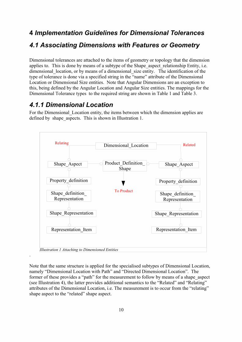
4.1.1 Dimensional LocationFor the Dimensional_Location entity, the items between which the dimension applies aredefined by shape_aspects. This is shown in Illustration 1.
.
Note that the same structure is applied for the specialised subtypes of Dimensional Location,namely “Dimensional Location with Path” and “Directed Dimensional Location”. Theformer of these provides a “path” for the measurement to follow by means of a shape_aspect(see Illustration 4), the latter provides additional semantics to the “Related” and “Relating”attributes of the Dimensional Location, i.e. The measurement is to occur from the “relating”shape aspect to the “related” shape aspect.
10
Illustration 1 Attaching to Dimensioned Entities
Dimensional_Location
Shape_Aspect Shape_AspectProduct_Definition_Shape
Property_definition Property_definition
Shape_definition_Representation
Shape_definition_Representation
Shape_Representation Shape_Representation
Representation_Item Representation_Item
To Product
Relating Related
Dimensions that map to a Dimensional Location are :
Dimensional Tolerance Dimensional Location.Name
Angular Location Dimension N/ACurved Distance Dimension 'curved distance'Linear Distance Dimension 'linear distance'
Table 1 Dimensional Location Types
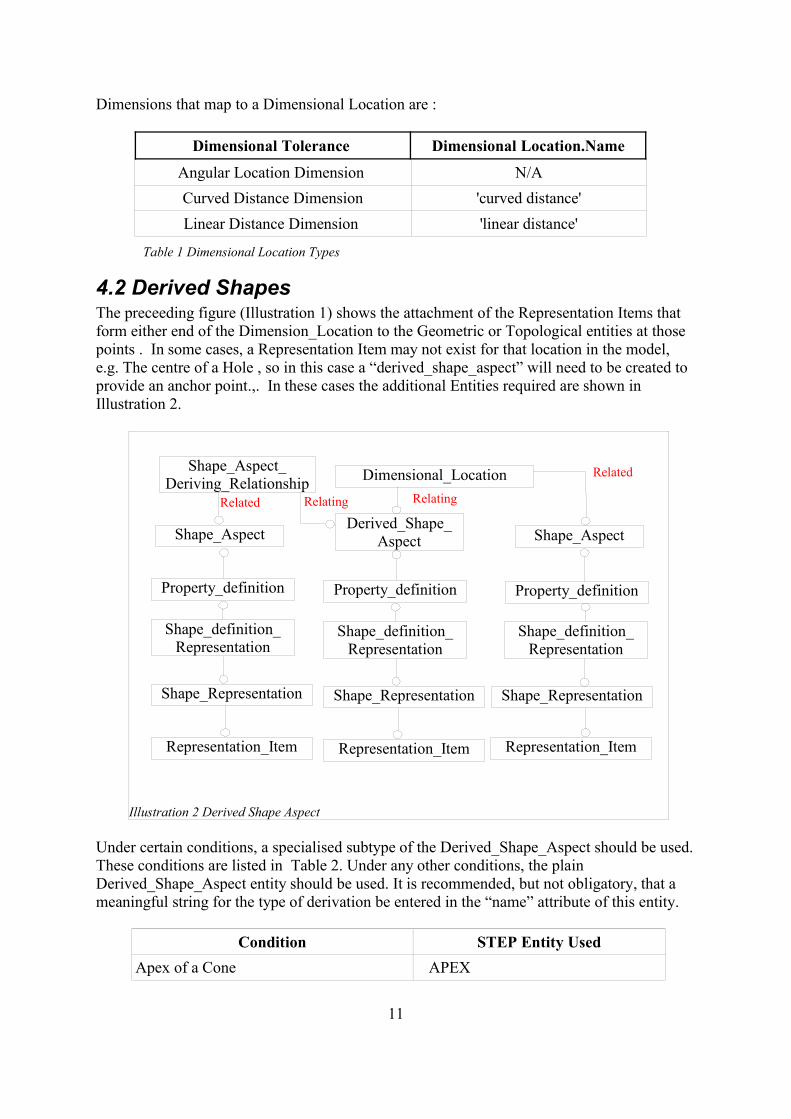
4.2 Derived ShapesThe preceeding figure (Illustration 1) shows the attachment of the Representation Items thatform either end of the Dimension_Location to the Geometric or Topological entities at thosepoints . In some cases, a Representation Item may not exist for that location in the model,e.g. The centre of a Hole , so in this case a “derived_shape_aspect” will need to be created toprovide an anchor point.,. In these cases the additional Entities required are shown inIllustration 2.
Under certain conditions, a specialised subtype of the Derived_Shape_Aspect should be used.These conditions are listed in Table 2. Under any other conditions, the plainDerived_Shape_Aspect entity should be used. It is recommended, but not obligatory, that ameaningful string for the type of derivation be entered in the “name” attribute of this entity.
Condition STEP Entity UsedApex of a Cone APEX
11
Illustration 2 Derived Shape Aspect
Dimensional_Location
Shape_Aspect Shape_Aspect
Property_definition Property_definition
Shape_definition_Representation
Shape_definition_Representation
Shape_Representation Shape_Representation
Representation_Item Representation_Item
Relating
Related
Derived_Shape_Aspect
Property_definition
Shape_definition_Representation
Shape_Representation
Representation_Item
Shape_Aspect_Deriving_Relationship
RelatingRelated
Condition STEP Entity UsedCentre of a Symmetrical Feature CENTRE_OF_SYMMETRYGeometric Alignment of two Features GEOMETRIC_ALIGNMENTPerpendicular to Feature PERPENDICULAR_TOSpatial Extension to Feature EXTENSIONTangential to Feature TANGENT Parallel Offset from Feature PARALLEL_OFFSET
Table 2 Types of Derived Shape
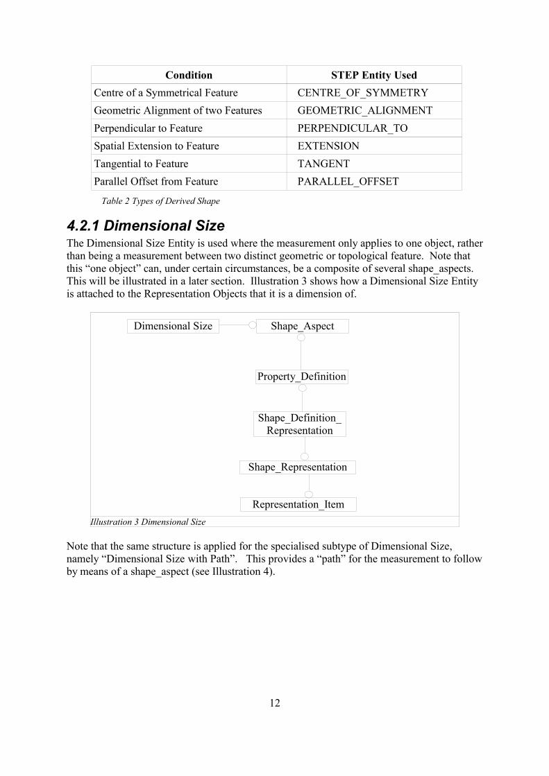
4.2.1 Dimensional SizeThe Dimensional Size Entity is used where the measurement only applies to one object, ratherthan being a measurement between two distinct geometric or topological feature. Note thatthis “one object” can, under certain circumstances, be a composite of several shape_aspects.This will be illustrated in a later section. Illustration 3 shows how a Dimensional Size Entityis attached to the Representation Objects that it is a dimension of.
Note that the same structure is applied for the specialised subtype of Dimensional Size,namely “Dimensional Size with Path”. This provides a “path” for the measurement to followby means of a shape_aspect (see Illustration 4).
12
Illustration 3 Dimensional Size
Dimensional Size Shape_Aspect
Property_Definition
Shape_Definition_Representation
Shape_Representation
Representation_Item
Dimensions that map to Dimensional Size are :
Dimensional Tolerance Dimensional Size.Name
Angular Size Dimension N/ACurved Size Dimension 'curve length'
Diameter Size Dimension 'diameter'Height Size Dimension 'height'Length Size Dimension 'length'Radial Size Dimension 'radius'
Thickness Size Dimension 'thickness size'Width Size Dimension 'width'
Table 3 Dimensional Size Types
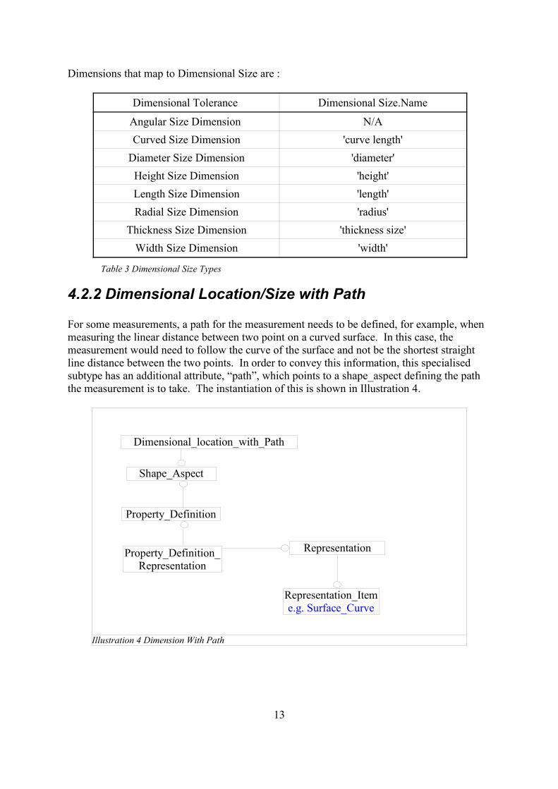
4.2.2 Dimensional Location/Size with Path
For some measurements, a path for the measurement needs to be defined, for example, whenmeasuring the linear distance between two point on a curved surface. In this case, themeasurement would need to follow the curve of the surface and not be the shortest straightline distance between the two points. In order to convey this information, this specialisedsubtype has an additional attribute, “path”, which points to a shape_aspect defining the paththe measurement is to take. The instantiation of this is shown in Illustration 4.
13
Illustration 4 Dimension With Path
Dimensional_location_with_Path
Shape_Aspect
Property_Definition
Property_Definition_Representation
Representation
Representation_Iteme.g. Surface_Curve
4.3 Application of Values to Identified Tolerances Once you have identified the tolerance and attached it to the relevant pieces of geometry ortopology as shown in the previous section, you can assign the tolerance value. The types ofvalue that can be applied are :
nominal value with a value limitnominal value with plus/minus boundsnominal value with value rangelimits and fits
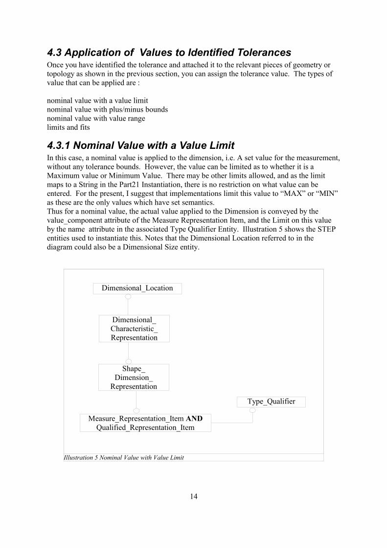
4.3.1 Nominal Value with a Value LimitIn this case, a nominal value is applied to the dimension, i.e. A set value for the measurement,without any tolerance bounds. However, the value can be limited as to whether it is aMaximum value or Minimum Value. There may be other limits allowed, and as the limitmaps to a String in the Part21 Instantiation, there is no restriction on what value can beentered. For the present, I suggest that implementations limit this value to “MAX” or “MIN”as these are the only values which have set semantics.Thus for a nominal value, the actual value applied to the Dimension is conveyed by thevalue_component attribute of the Measure Representation Item, and the Limit on this valueby the name attribute in the associated Type Qualifier Entity. Illustration 5 shows the STEPentities used to instantiate this. Notes that the Dimensional Location referred to in thediagram could also be a Dimensional Size entity.
14
Illustration 5 Nominal Value with Value Limit
Dimensional_Location
Dimensional_Characteristic_Representation
Shape_Dimension_
Representation
Measure_Representation_Item ANDQualified_Representation_Item
Type_Qualifier
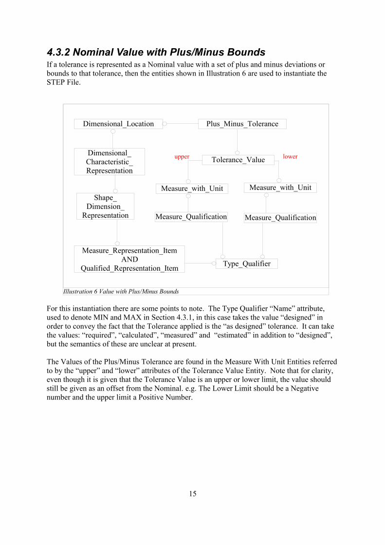
4.3.2 Nominal Value with Plus/Minus BoundsIf a tolerance is represented as a Nominal value with a set of plus and minus deviations orbounds to that tolerance, then the entities shown in Illustration 6 are used to instantiate theSTEP File.
For this instantiation there are some points to note. The Type Qualifier “Name” attribute,used to denote MIN and MAX in Section 4.3.1, in this case takes the value “designed” inorder to convey the fact that the Tolerance applied is the “as designed” tolerance. It can takethe values: “required”, “calculated”, “measured” and “estimated” in addition to “designed”,but the semantics of these are unclear at present.
The Values of the Plus/Minus Tolerance are found in the Measure With Unit Entities referredto by the “upper” and “lower” attributes of the Tolerance Value Entity. Note that for clarity,even though it is given that the Tolerance Value is an upper or lower limit, the value shouldstill be given as an offset from the Nominal. e.g. The Lower Limit should be a Negativenumber and the upper limit a Positive Number.
15
Illustration 6 Value with Plus/Minus Bounds
Dimensional_Location
Dimensional_Characteristic_Representation
Shape_Dimension_
Representation
Measure_Representation_Item AND
Qualified_Representation_Item Type_Qualifier
Plus_Minus_Tolerance
Tolerance_Value
Measure_with_Unit Measure_with_Unit
Measure_Qualification Measure_Qualification
upper lower
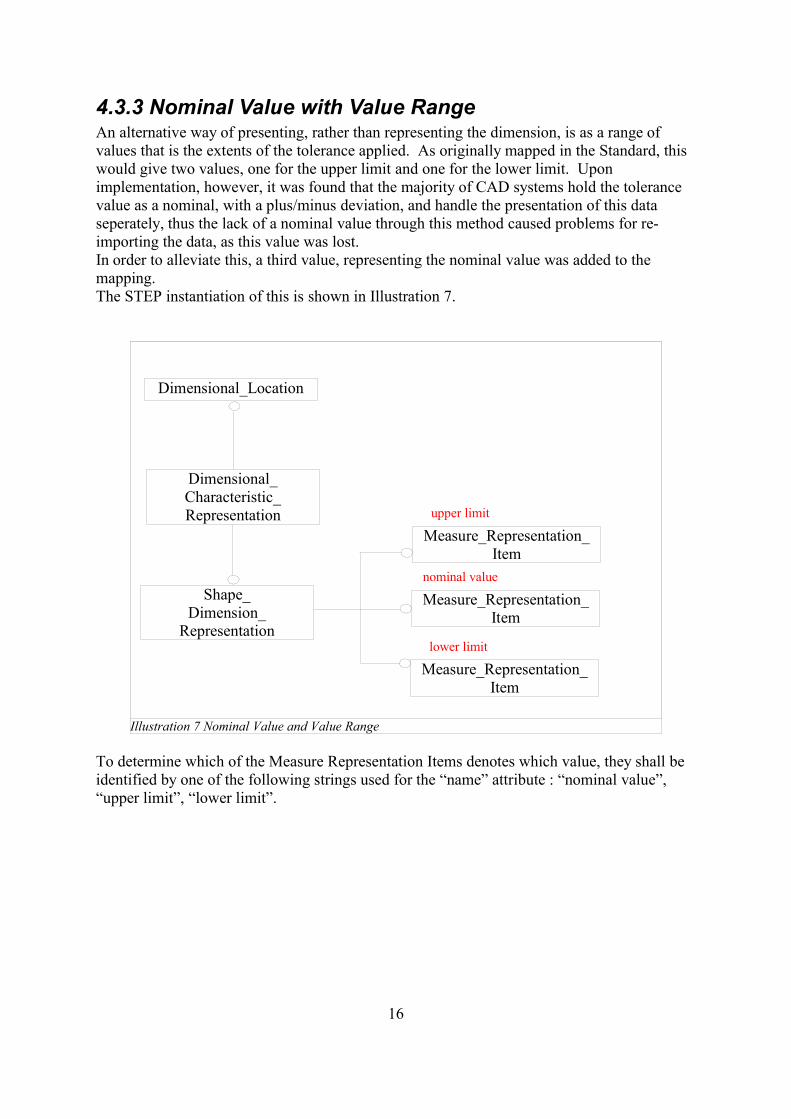
4.3.3 Nominal Value with Value RangeAn alternative way of presenting, rather than representing the dimension, is as a range ofvalues that is the extents of the tolerance applied. As originally mapped in the Standard, thiswould give two values, one for the upper limit and one for the lower limit. Uponimplementation, however, it was found that the majority of CAD systems hold the tolerancevalue as a nominal, with a plus/minus deviation, and handle the presentation of this dataseperately, thus the lack of a nominal value through this method caused problems for re-importing the data, as this value was lost.In order to alleviate this, a third value, representing the nominal value was added to themapping.The STEP instantiation of this is shown in Illustration 7.
To determine which of the Measure Representation Items denotes which value, they shall beidentified by one of the following strings used for the “name” attribute : “nominal value”,“upper limit”, “lower limit”.
16
Illustration 7 Nominal Value and Value Range
Dimensional_Location
Dimensional_Characteristic_Representation
Shape_Dimension_
Representation
Measure_Representation_Item
Measure_Representation_Item
Measure_Representation_Item
upper limit
lower limit
nominal value
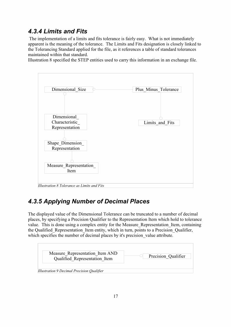
4.3.4 Limits and Fits The implementation of a limits and fits tolerance is fairly easy. What is not immediatelyapparent is the meaning of the tolerance. The Limits and Fits designation is closely linked tothe Tolerancing Standard applied for the file, as it references a table of standard tolerancesmaintained within that standard. Illustration 8 specified the STEP entities used to carry this information in an exchange file.
4.3.5 Applying Number of Decimal Places
The displayed value of the Dimensional Tolerance can be truncated to a number of decimalplaces, by specifying a Precision Qualifier to the Representation Item which hold to tolerancevalue. This is done using a complex entity for the Measure_Representation_Item, containingthe Qualified_Representation_Item entity, which in turn, points to a Precision_Qualifier,which specifies the number of decimal places by it's precision_value attribute.
17
Illustration 8 Tolerance as Limits and Fits
Dimensional_Size
Dimensional_Characteristic_Representation
Shape_Dimension_Representation
Measure_Representation_Item
Plus_Minus_Tolerance
Limits_and_Fits
Illustration 9 Decimal Precision Qualifier
Measure_Representation_Item ANDQualified_Representation_Item Precision_Qualifier
5 Implementation Guidelines For GD&T Representation
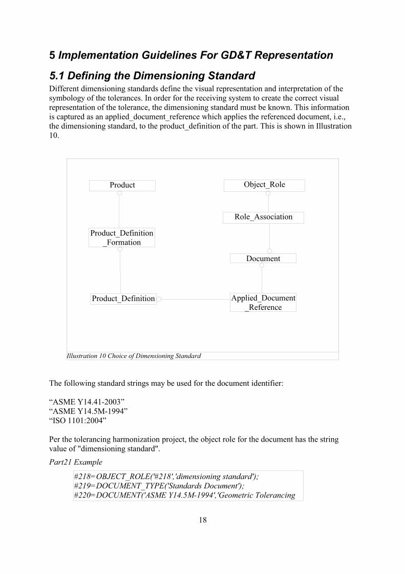
5.1 Defining the Dimensioning Standard Different dimensioning standards define the visual representation and interpretation of thesymbology of the tolerances. In order for the receiving system to create the correct visualrepresentation of the tolerance, the dimensioning standard must be known. This informationis captured as an applied_document_reference which applies the referenced document, i.e.,the dimensioning standard, to the product_definition of the part. This is shown in Illustration10.
The following standard strings may be used for the document identifier:
“ASME Y14.41-2003”“ASME Y14.5M-1994”“ISO 1101:2004”
Per the tolerancing harmonization project, the object role for the document has the stringvalue of "dimensioning standard".
Part21 Example
#218=OBJECT_ROLE('#218','dimensioning standard');#219=DOCUMENT_TYPE('Standards Document');#220=DOCUMENT('ASME Y14.5M-1994','Geometric Tolerancing
18
Illustration 10 Choice of Dimensioning Standard
Object_Role
Role_Association
Document
Applied_Document_Reference
Product_Definition
Product_Definition_Formation
Product
Standard','Geometric Tolerancing Standard',#219);#221=ROLE_ASSOCIATION(#218,#220);#222=APPLIED_DOCUMENT_REFERENCE(#220,'StandardsBody',(#167));
5.2 Associating tolerances with Features
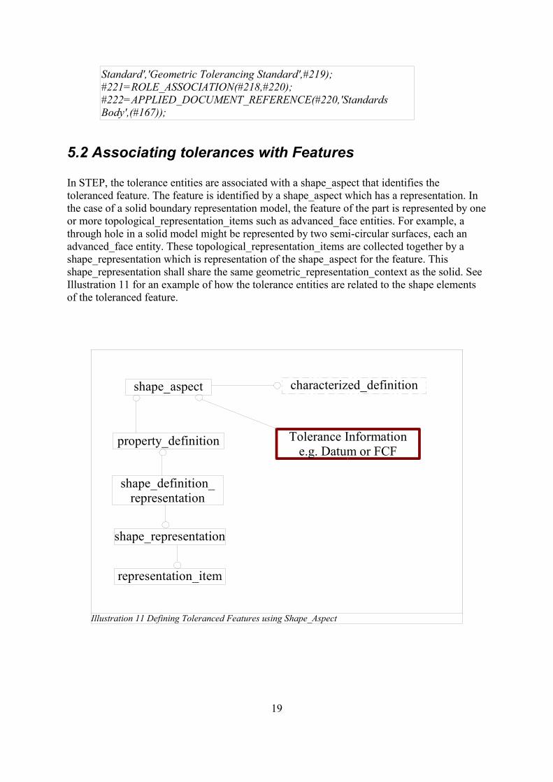
In STEP, the tolerance entities are associated with a shape_aspect that identifies thetoleranced feature. The feature is identified by a shape_aspect which has a representation. Inthe case of a solid boundary representation model, the feature of the part is represented by oneor more topological_representation_items such as advanced_face entities. For example, athrough hole in a solid model might be represented by two semi-circular surfaces, each anadvanced_face entity. These topological_representation_items are collected together by ashape_representation which is representation of the shape_aspect for the feature. Thisshape_representation shall share the same geometric_representation_context as the solid. SeeIllustration 11 for an example of how the tolerance entities are related to the shape elementsof the toleranced feature.
19
Illustration 11 Defining Toleranced Features using Shape_Aspect
shape_aspect
property_definition
shape_definition_representation
shape_representation
representation_item
Tolerance Informatione.g. Datum or FCF
characterized_definition
Part 21 Example#187=ADVANCED_FACE('feature face',(#181),#186,.T.);#252=PRODUCT_DEFINITION_SHAPE('',$,#17);#315=SHAPE_ASPECT('',$,#252,.T.);#316=PROPERTY_DEFINITION('',$,#315);#317=SHAPE_REPRESENTATION('',(#187),#246);#318=SHAPE_DEFINITION_REPRESENTATION(#316,#317);#320=FLATNESS_TOLERANCE('#320','flatness tolerance',#319,#315);
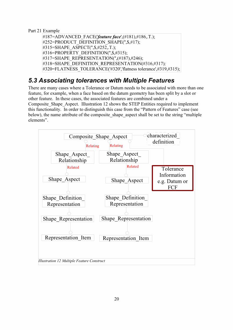
5.3 Associating tolerances with Multiple FeaturesThere are many cases where a Tolerance or Datum needs to be associated with more than onefeature, for example, when a face based on the datum geometry has been split by a slot orother feature. In these cases, the associated features are combined under aComposite_Shape_Aspect. Illustration 12 shows the STEP Entities required to implementthis functionality. In order to distinguish this case from the “Pattern of Features” case (seebelow), the name attribute of the composite_shape_aspect shall be set to the string “multipleelements”.
20
Illustration 12 Multiple Feature Construct
Composite_Shape_Aspect
Shape_Aspect_Relationship
Shape_Aspect_Relationship
Shape_Aspect Shape_Aspect
Shape_Definition_Representation
Shape_Definition_Representation
Shape_Representation Shape_Representation
Representation_Item Representation_Item
Tolerance Information
e.g. Datum or FCF
characterized_definition
Related Related
RelatingRelating
Part 21 Example
#10341=PRODUCT_DEFINITION_SHAPE('',$,#17);#10396=SHAPE_ASPECT('',$,#10341,.T.);#10397=PROPERTY_DEFINITION('',$,#10396);#10398=SHAPE_REPRESENTATION('',(#5423),#10335);#10399=SHAPE_DEFINITION_REPRESENTATION(#10397,#10398);#10400=SHAPE_ASPECT('',$,#10341,.T.);#10401=PROPERTY_DEFINITION('',$,#10400);#10402=SHAPE_REPRESENTATION('',(#5411),#10335);#10403=SHAPE_DEFINITION_REPRESENTATION(#10401,#10402);#10404=COMPOSITE_SHAPE_ASPECT('multiple elements',$,#10341,.T.);#10405=SHAPE_ASPECT_RELATIONSHIP('',$,#10404,#10396);#10406=SHAPE_ASPECT_RELATIONSHIP('',$,#10404,#10400);
5.3.1 Associating tolerances with a Pattern of Features
One of the uses of the Multiple Feature construct is allowing the exchange of Tolerancesapplied to a pattern of features. In order to differentiate this from the normal case, the string“pattern of features” is used to populate the composite_shape_aspect.name attribute.e.g. #299=COMPOSITE_SHAPE_ASPECT('pattern of features',$,#246,.T.);
21
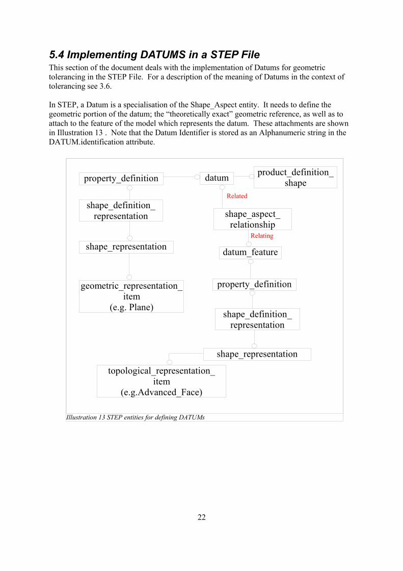
5.4 Implementing DATUMS in a STEP FileThis section of the document deals with the implementation of Datums for geometrictolerancing in the STEP File. For a description of the meaning of Datums in the context oftolerancing see 3.6.
In STEP, a Datum is a specialisation of the Shape_Aspect entity. It needs to define thegeometric portion of the datum; the “theoretically exact” geometric reference, as well as toattach to the feature of the model which represents the datum. These attachments are shownin Illustration 13 . Note that the Datum Identifier is stored as an Alphanumeric string in theDATUM.identification attribute.
22
Illustration 13 STEP entities for defining DATUMs
datumproperty_definition
shape_definition_representation
shape_representation
geometric_representation_item
(e.g. Plane)
property_definition
shape_definition_representation
shape_representation
datum_feature
topological_representation_item
(e.g.Advanced_Face)
shape_aspect_relationship
product_definition_shape
Relating
Related

Part21 Example
#180=PLANE('',#179);#181=ADVANCED_FACE('',(#175),#180,.T.);#265=DATUM('#',$,#246,.F.,'B');#266=SHAPE_REPRESENTATION('',(#180),#240);#267=PROPERTY_DEFINITION('#',$,#265);#268=SHAPE_DEFINITION_REPRESENTATION(#267,#266);#269=DATUM_FEATURE('',$,#246,.T.);#270=SHAPE_ASPECT_RELATIONSHIP('',$,#269,#265);#271=PROPERTY_DEFINITION('',$,#269);#272=SHAPE_REPRESENTATION('',(#181),#240);#273=SHAPE_DEFINITION_REPRESENTATION(#271,#272);
5.5 Implementing DATUM TARGETS in a STEP File
A Datum Target is a point, line or limited area of the part surface that is used in theconstruction of a Datum, when it is not practical to use an entire feature nor a substantialregion. A Datum is constructed from one or more Datum Targets, and may be offset from thepart surface. The implementation of Datum Targets is done by relating thePlaced_Datum_Target_Feature to the Datum it is part of the definition of, by means of aShape_Aspect_relationship. This is shown in Illustration 14.
23
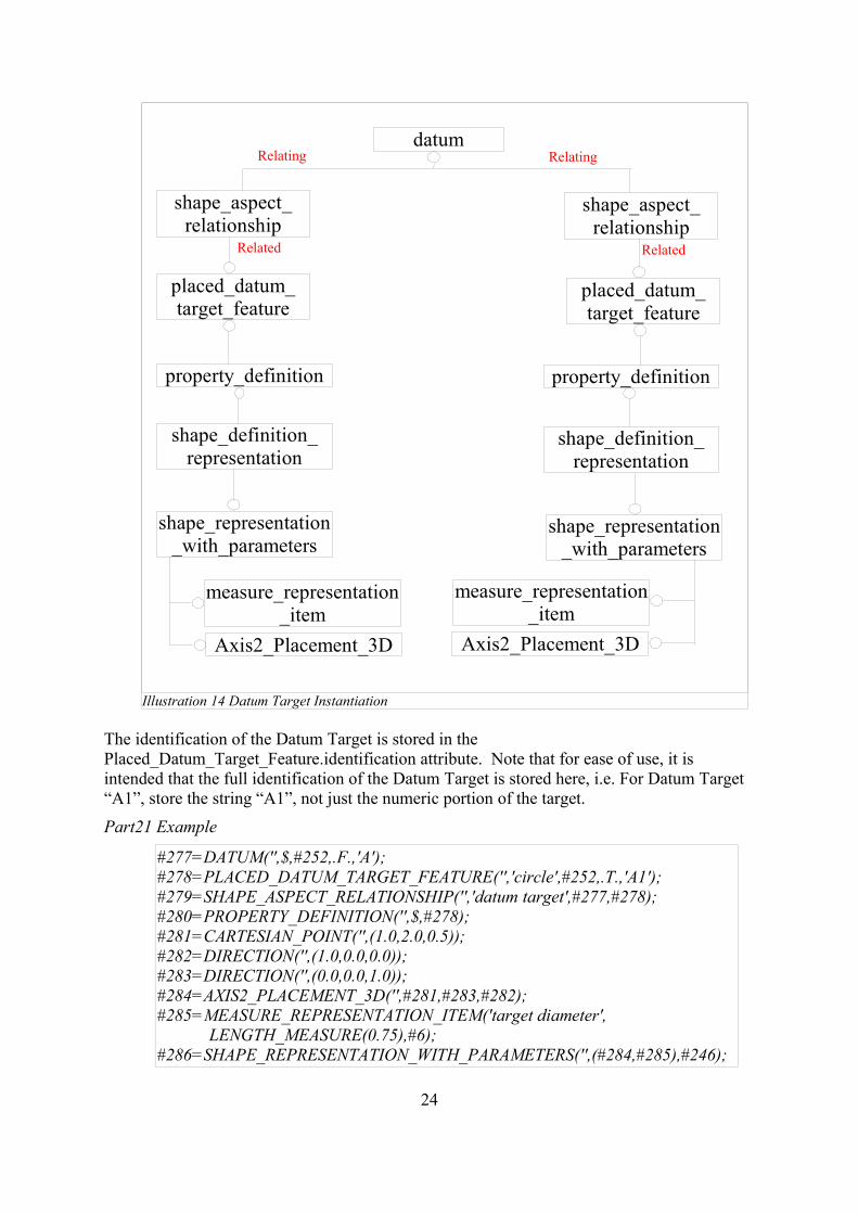
The identification of the Datum Target is stored in thePlaced_Datum_Target_Feature.identification attribute. Note that for ease of use, it isintended that the full identification of the Datum Target is stored here, i.e. For Datum Target“A1”, store the string “A1”, not just the numeric portion of the target.
Part21 Example
#277=DATUM('',$,#252,.F.,'A');#278=PLACED_DATUM_TARGET_FEATURE('','circle',#252,.T.,'A1');#279=SHAPE_ASPECT_RELATIONSHIP('','datum target',#277,#278);#280=PROPERTY_DEFINITION('',$,#278);#281=CARTESIAN_POINT('',(1.0,2.0,0.5));#282=DIRECTION('',(1.0,0.0,0.0));#283=DIRECTION('',(0.0,0.0,1.0));#284=AXIS2_PLACEMENT_3D('',#281,#283,#282);#285=MEASURE_REPRESENTATION_ITEM('target diameter', LENGTH_MEASURE(0.75),#6);#286=SHAPE_REPRESENTATION_WITH_PARAMETERS('',(#284,#285),#246);
24
Illustration 14 Datum Target Instantiation
datum
shape_aspect_relationship
shape_aspect_relationship
placed_datum_target_feature
placed_datum_target_feature
property_definition property_definition
shape_definition_representation
shape_definition_representation
shape_representation_with_parameters
shape_representation_with_parameters
measure_representation_item
measure_representation_item
Axis2_Placement_3D Axis2_Placement_3D
Relating Relating
Related Related
#287=SHAPE_DEFINITION_REPRESENTATION(#280,#286);#288=PLACED_DATUM_TARGET_FEATURE('','circle',#252,.T.,'A2');#289=SHAPE_ASPECT_RELATIONSHIP('','datum target',#277,#288);#290=PROPERTY_DEFINITION('',$,#288);#291=CARTESIAN_POINT('',(3.0,2.0,0.5));#292=DIRECTION('',(1.0,0.0,0.0));#293=DIRECTION('',(0.0,0.0,1.0));#294=AXIS2_PLACEMENT_3D('',#291,#293,#292);#295=MEASURE_REPRESENTATION_ITEM('target diameter', LENGTH_MEASURE(0.5),#6);#296=SHAPE_REPRESENTATION_WITH_PARAMETERS('',(#294,#295),#246);#297=SHAPE_DEFINITION_REPRESENTATION(#290,#296);
5.5.1 DATUM TARGET types
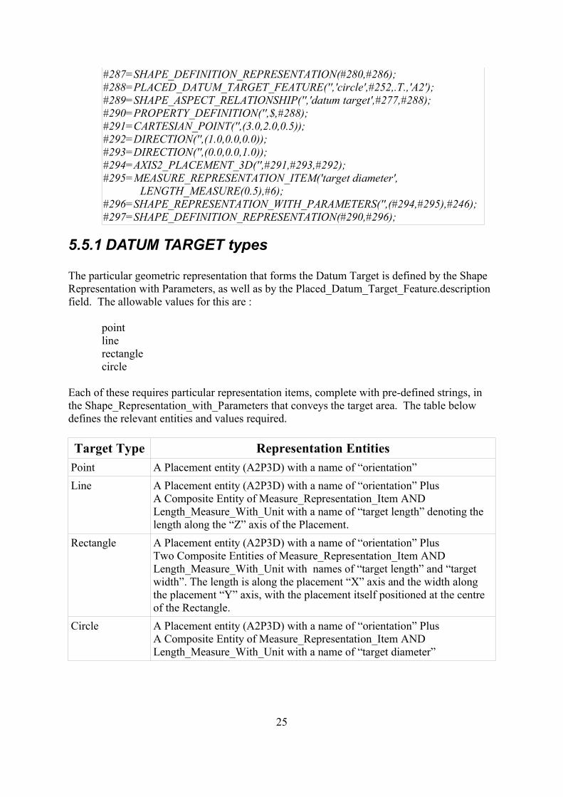
The particular geometric representation that forms the Datum Target is defined by the ShapeRepresentation with Parameters, as well as by the Placed_Datum_Target_Feature.descriptionfield. The allowable values for this are :
pointline rectangle circle
Each of these requires particular representation items, complete with pre-defined strings, inthe Shape_Representation_with_Parameters that conveys the target area. The table belowdefines the relevant entities and values required.
Target Type Representation EntitiesPoint A Placement entity (A2P3D) with a name of “orientation”Line A Placement entity (A2P3D) with a name of “orientation” Plus
A Composite Entity of Measure_Representation_Item ANDLength_Measure_With_Unit with a name of “target length” denoting thelength along the “Z” axis of the Placement.
Rectangle A Placement entity (A2P3D) with a name of “orientation” PlusTwo Composite Entities of Measure_Representation_Item ANDLength_Measure_With_Unit with names of “target length” and “targetwidth”. The length is along the placement “X” axis and the width alongthe placement “Y” axis, with the placement itself positioned at the centreof the Rectangle.
Circle A Placement entity (A2P3D) with a name of “orientation” PlusA Composite Entity of Measure_Representation_Item ANDLength_Measure_With_Unit with a name of “target diameter”
25
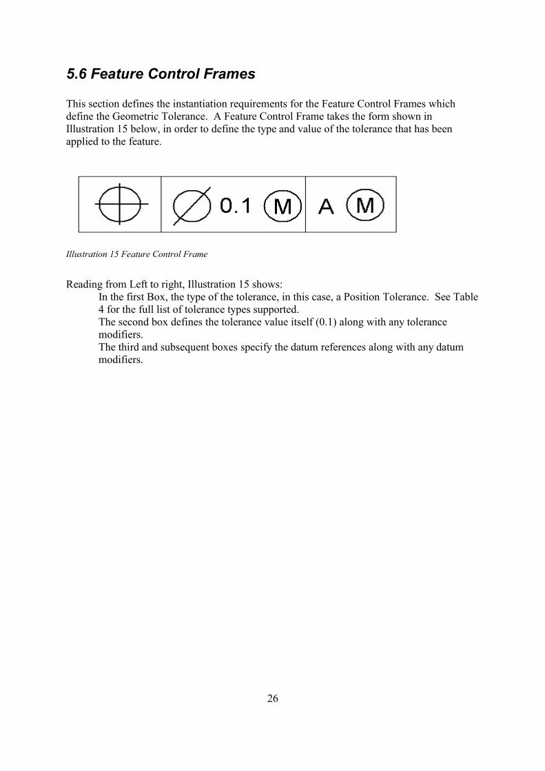
5.6 Feature Control Frames
This section defines the instantiation requirements for the Feature Control Frames whichdefine the Geometric Tolerance. A Feature Control Frame takes the form shown inIllustration 15 below, in order to define the type and value of the tolerance that has beenapplied to the feature.
Illustration 15 Feature Control Frame
Reading from Left to right, Illustration 15 shows:In the first Box, the type of the tolerance, in this case, a Position Tolerance. See Table4 for the full list of tolerance types supported.The second box defines the tolerance value itself (0.1) along with any tolerancemodifiers.The third and subsequent boxes specify the datum references along with any datummodifiers.
26
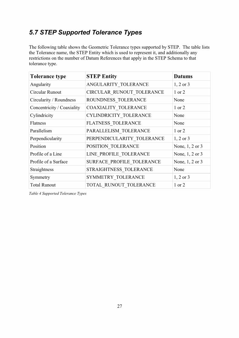
5.7 STEP Supported Tolerance Types
The following table shows the Geometric Tolerance types supported by STEP. The table liststhe Tolerance name, the STEP Entity which is used to represent it, and additionally anyrestrictions on the number of Datum References that apply in the STEP Schema to thattolerance type.
Tolerance type STEP Entity DatumsAngularity ANGULARITY_TOLERANCE 1, 2 or 3Circular Runout CIRCULAR_RUNOUT_TOLERANCE 1 or 2Circularity / Roundness ROUNDNESS_TOLERANCE NoneConcentricity / Coaxiality COAXIALITY_TOLERANCE 1 or 2Cylindricity CYLINDRICITY_TOLERANCE NoneFlatness FLATNESS_TOLERANCE NoneParallelism PARALLELISM_TOLERANCE 1 or 2Perpendicularity PERPENDICULARITY_TOLERANCE 1, 2 or 3Position POSITION_TOLERANCE None, 1, 2 or 3Profile of a Line LINE_PROFILE_TOLERANCE None, 1, 2 or 3Profile of a Surface SURFACE_PROFILE_TOLERANCE None, 1, 2 or 3Straightness STRAIGHTNESS_TOLERANCE NoneSymmetry SYMMETRY_TOLERANCE 1, 2 or 3Total Runout TOTAL_RUNOUT_TOLERANCE 1 or 2
Table 4 Supported Tolerance Types
27
5.8 Implementing Feature Control Frames
The STEP file implementation of the Geometric Tolerances makes use of the entities shownin the sections below, each section showing the entities required for the different cases, i.e.tolerance without modification or datums, tolerance with datums and modified tolerances.Note that the linkage to the Feature(s) being toleranced is covered in Illustration 11 andIllustration 12.
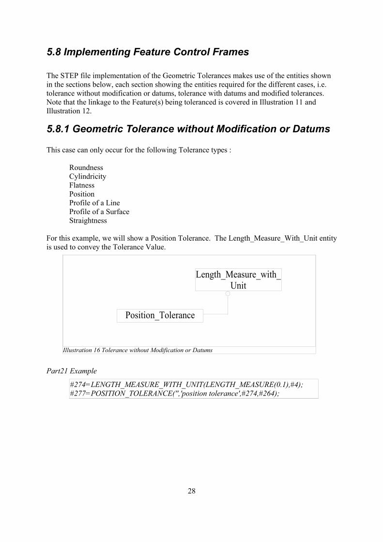
5.8.1 Geometric Tolerance without Modification or Datums
This case can only occur for the following Tolerance types :
RoundnessCylindricityFlatnessPositionProfile of a LineProfile of a SurfaceStraightness
For this example, we will show a Position Tolerance. The Length_Measure_With_Unit entityis used to convey the Tolerance Value.
Part21 Example
#274=LENGTH_MEASURE_WITH_UNIT(LENGTH_MEASURE(0.1),#4);#277=POSITION_TOLERANCE('','position tolerance',#274,#264);
28
Illustration 16 Tolerance without Modification or Datums
Position_Tolerance
Length_Measure_with_Unit
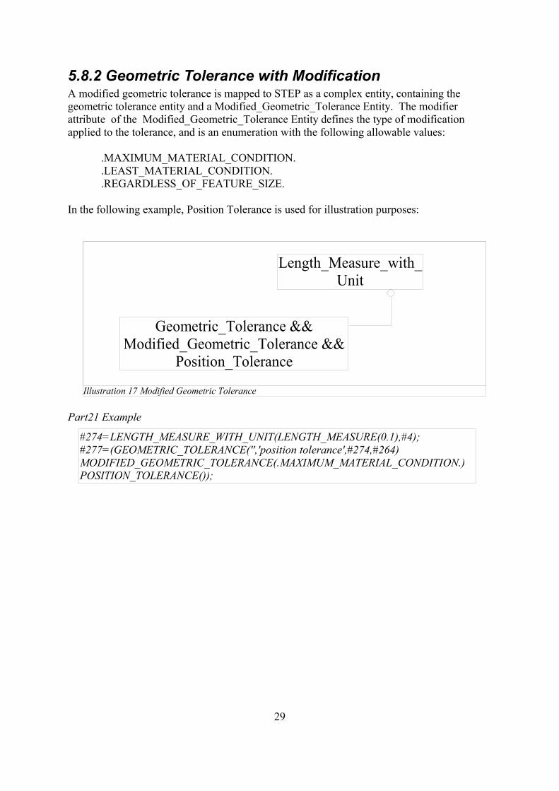
5.8.2 Geometric Tolerance with ModificationA modified geometric tolerance is mapped to STEP as a complex entity, containing thegeometric tolerance entity and a Modified_Geometric_Tolerance Entity. The modifierattribute of the Modified_Geometric_Tolerance Entity defines the type of modificationapplied to the tolerance, and is an enumeration with the following allowable values:
.MAXIMUM_MATERIAL_CONDITION.
.LEAST_MATERIAL_CONDITION.
.REGARDLESS_OF_FEATURE_SIZE.
In the following example, Position Tolerance is used for illustration purposes:
Part21 Example
#274=LENGTH_MEASURE_WITH_UNIT(LENGTH_MEASURE(0.1),#4);#277=(GEOMETRIC_TOLERANCE('','position tolerance',#274,#264)MODIFIED_GEOMETRIC_TOLERANCE(.MAXIMUM_MATERIAL_CONDITION.)POSITION_TOLERANCE());
29
Illustration 17 Modified Geometric Tolerance
Geometric_Tolerance && Modified_Geometric_Tolerance &&
Position_Tolerance
Length_Measure_with_Unit
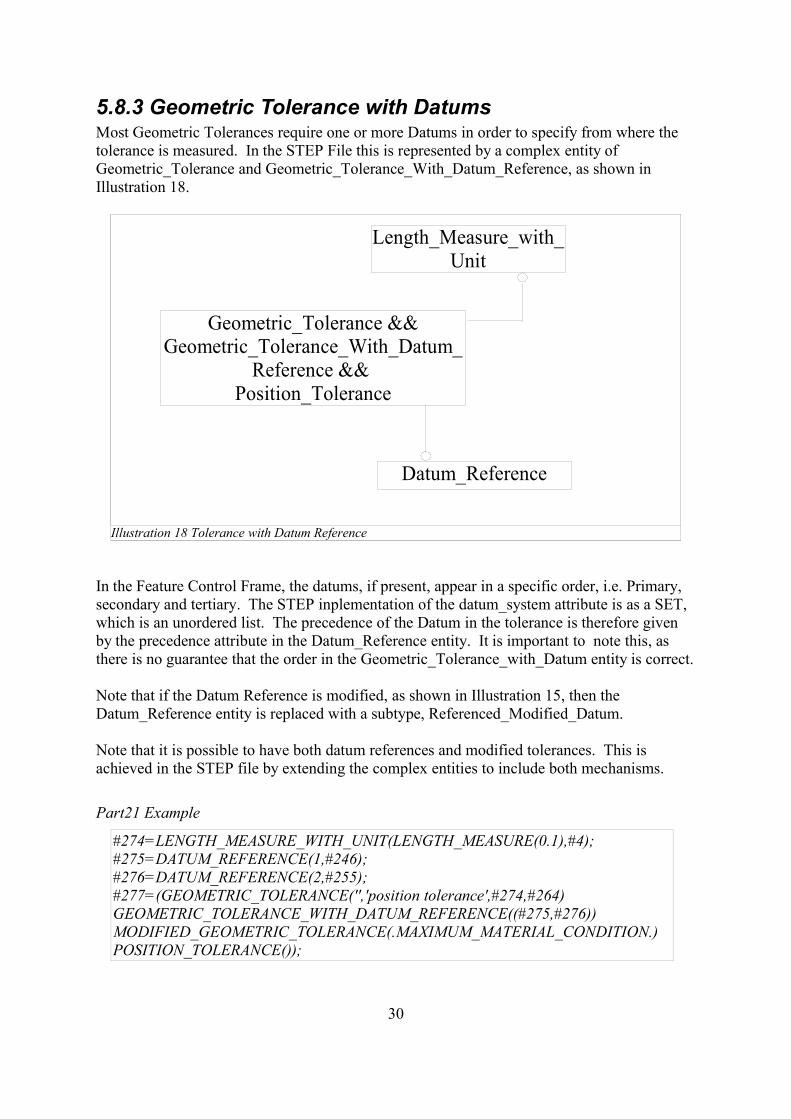
5.8.3 Geometric Tolerance with DatumsMost Geometric Tolerances require one or more Datums in order to specify from where thetolerance is measured. In the STEP File this is represented by a complex entity ofGeometric_Tolerance and Geometric_Tolerance_With_Datum_Reference, as shown inIllustration 18.
In the Feature Control Frame, the datums, if present, appear in a specific order, i.e. Primary,secondary and tertiary. The STEP inplementation of the datum_system attribute is as a SET,which is an unordered list. The precedence of the Datum in the tolerance is therefore givenby the precedence attribute in the Datum_Reference entity. It is important to note this, asthere is no guarantee that the order in the Geometric_Tolerance_with_Datum entity is correct.
Note that if the Datum Reference is modified, as shown in Illustration 15, then theDatum_Reference entity is replaced with a subtype, Referenced_Modified_Datum.
Note that it is possible to have both datum references and modified tolerances. This isachieved in the STEP file by extending the complex entities to include both mechanisms.
Part21 Example
#274=LENGTH_MEASURE_WITH_UNIT(LENGTH_MEASURE(0.1),#4);#275=DATUM_REFERENCE(1,#246);#276=DATUM_REFERENCE(2,#255);#277=(GEOMETRIC_TOLERANCE('','position tolerance',#274,#264)GEOMETRIC_TOLERANCE_WITH_DATUM_REFERENCE((#275,#276))MODIFIED_GEOMETRIC_TOLERANCE(.MAXIMUM_MATERIAL_CONDITION.)POSITION_TOLERANCE());
30
Illustration 18 Tolerance with Datum Reference
Geometric_Tolerance && Geometric_Tolerance_With_Datum_
Reference && Position_Tolerance
Length_Measure_with_Unit
Datum_Reference
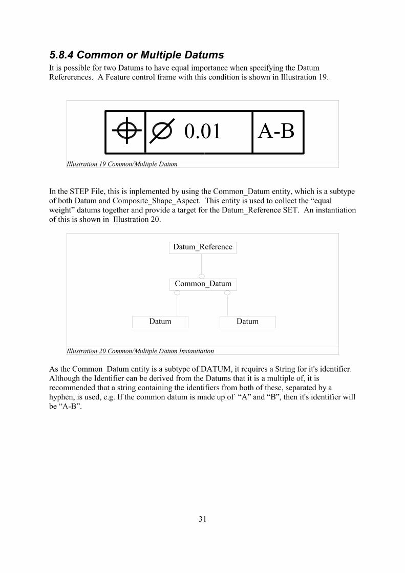
5.8.4 Common or Multiple DatumsIt is possible for two Datums to have equal importance when specifying the DatumRefererences. A Feature control frame with this condition is shown in Illustration 19.
In the STEP File, this is inplemented by using the Common_Datum entity, which is a subtypeof both Datum and Composite_Shape_Aspect. This entity is used to collect the “equalweight” datums together and provide a target for the Datum_Reference SET. An instantiationof this is shown in Illustration 20.
As the Common_Datum entity is a subtype of DATUM, it requires a String for it's identifier.Although the Identifier can be derived from the Datums that it is a multiple of, it isrecommended that a string containing the identifiers from both of these, separated by ahyphen, is used, e.g. If the common datum is made up of “A” and “B”, then it's identifier willbe “A-B”.
31
Illustration 19 Common/Multiple Datum
0.01 A-B
Illustration 20 Common/Multiple Datum Instantiation
Common_Datum
Datum_Reference
Datum Datum
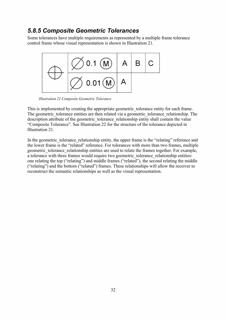
5.8.5 Composite Geometric TolerancesSome tolerances have multiple requirements as represented by a multiple frame tolerancecontrol frame whose visual representation is shown in Illustration 21.
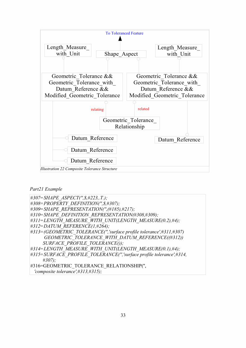
This is implemented by creating the appropriate geometric_tolerance entity for each frame.The geometric_tolerance entities are then related via a geometric_tolerance_relationship. Thedescription attribute of the geometric_tolerance_relationship entity shall contain the value“Composite Tolerance”. See Illustration 22 for the structure of the tolerance depicted inIllustration 21.
In the geometric_tolerance_relationship entity, the upper frame is the “relating” reference andthe lower frame is the “related” reference. For tolerances with more than two frames, multiplegeometric_tolerance_relationship entities are used to relate the frames together. For example,a tolerance with three frames would require two geometric_tolerance_relationship entities:one relating the top (“relating”) and middle frames (“related”), the second relating the middle(“relating”) and the bottom (“related”) frames. These relationships will allow the receiver toreconstruct the semantic relationships as well as the visual representation.
32
Illustration 21 Composite Geometric Tolerance
Part21 Example
#307=SHAPE_ASPECT('',$,#223,.T.);#308=PROPERTY_DEFINITION('',$,#307);#309=SHAPE_REPRESENTATION('',(#185),#217);#310=SHAPE_DEFINITION_REPRESENTATION(#308,#309);#311=LENGTH_MEASURE_WITH_UNIT(LENGTH_MEASURE(0.2),#4);#312=DATUM_REFERENCE(1,#264);#313=(GEOMETRIC_TOLERANCE('','surface profile tolerance',#311,#307) GEOMETRIC_TOLERANCE_WITH_DATUM_REFERENCE((#312)) SURFACE_PROFILE_TOLERANCE());#314=LENGTH_MEASURE_WITH_UNIT(LENGTH_MEASURE(0.1),#4);#315=SURFACE_PROFILE_TOLERANCE('','surface profile tolerance',#314, #307);#316=GEOMETRIC_TOLERANCE_RELATIONSHIP('', 'composite tolerance',#313,#315);
33
Illustration 22 Composite Tolerance Structure
Shape_AspectLength_Measure_
with_UnitLength_Measure_
with_Unit
Geometric_Tolerance_Relationship
Geometric_Tolerance &&Geometric_Tolerance_with_
Datum_Reference &&Modified_Geometric_Tolerance
Geometric_Tolerance &&Geometric_Tolerance_with_
Datum_Reference &&Modified_Geometric_Tolerance
Datum_ReferenceDatum_Reference
Datum_Reference
Datum_Reference
relating related
To Toleranced Feature
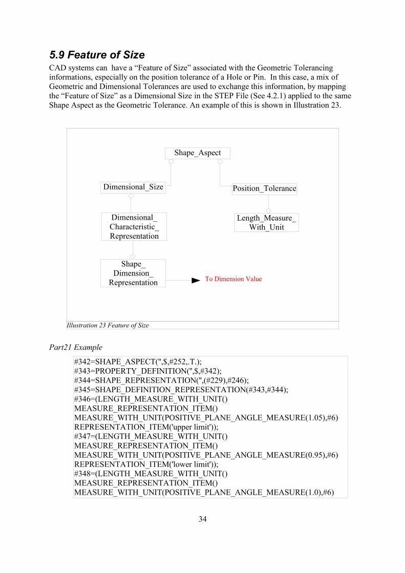
5.9 Feature of SizeCAD systems can have a “Feature of Size” associated with the Geometric Tolerancinginformations, especially on the position tolerance of a Hole or Pin. In this case, a mix ofGeometric and Dimensional Tolerances are used to exchange this information, by mappingthe “Feature of Size” as a Dimensional Size in the STEP File (See 4.2.1) applied to the sameShape Aspect as the Geometric Tolerance. An example of this is shown in Illustration 23.
Part21 Example
#342=SHAPE_ASPECT('',$,#252,.T.);#343=PROPERTY_DEFINITION('',$,#342);#344=SHAPE_REPRESENTATION('',(#229),#246);#345=SHAPE_DEFINITION_REPRESENTATION(#343,#344);#346=(LENGTH_MEASURE_WITH_UNIT()MEASURE_REPRESENTATION_ITEM()MEASURE_WITH_UNIT(POSITIVE_PLANE_ANGLE_MEASURE(1.05),#6)REPRESENTATION_ITEM('upper limit'));#347=(LENGTH_MEASURE_WITH_UNIT()MEASURE_REPRESENTATION_ITEM()MEASURE_WITH_UNIT(POSITIVE_PLANE_ANGLE_MEASURE(0.95),#6)REPRESENTATION_ITEM('lower limit'));#348=(LENGTH_MEASURE_WITH_UNIT()MEASURE_REPRESENTATION_ITEM()MEASURE_WITH_UNIT(POSITIVE_PLANE_ANGLE_MEASURE(1.0),#6)
34
Illustration 23 Feature of Size
Shape_Aspect
Dimensional_Size Position_Tolerance
Length_Measure_With_Unit
Dimensional_Characteristic_Representation
Shape_Dimension_
Representation To Dimension Value
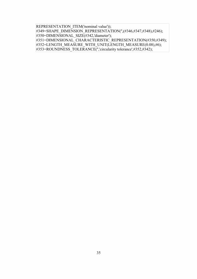
REPRESENTATION_ITEM('nominal value'));#349=SHAPE_DIMENSION_REPRESENTATION('',(#346,#347,#348),#246);#350=DIMENSIONAL_SIZE(#342,'diameter');#351=DIMENSIONAL_CHARACTERISTIC_REPRESENTATION(#350,#349);#352=LENGTH_MEASURE_WITH_UNIT(LENGTH_MEASURE(0.08),#6);#353=ROUNDNESS_TOLERANCE('','circularity tolerance',#352,#342);
35
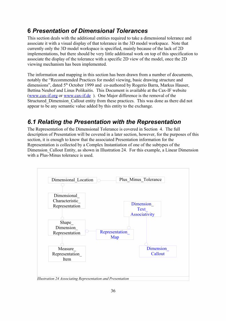
6 Presentation of Dimensional TolerancesThis section deals with the additional entities required to take a dimensional tolerance andassociate it with a visual display of that tolerance in the 3D model workspace. Note thatcurrently only the 3D model workspace is specified, mainly because of the lack of 2Dimplementations, but there should be very little additional work on top of this specification toassociate the display of the tolerance with a specific 2D view of the model, once the 2Dviewing mechanism has been implemented.
The information and mapping in this section has been drawn from a number of documents,notably the “Recommended Practices for model viewing, basic drawing structure anddimensions”, dated 5th October 1999 and co-authored by Rogerio Barra, Markus Hauser,Bettina Neuhof and Linus Polikaitis. This Document is available at the Cax-IF website(www.cax-if.org or www.cax-if.de ). One Major difference is the removal of theStructured_Dimension_Callout entity from these practices. This was done as there did notappear to be any semantic value added by this entity to the exchange.
6.1 Relating the Presentation with the RepresentationThe Representation of the Dimensional Tolerance is covered in Section 4. The fulldescription of Presentation will be covered in a later section, however, for the purposes of thissection, it is enough to know that the associated Presentation information for theRepresentation is collected by a Complex Instantiation of one of the subtypes of theDimension_Callout Entity, as shown in Illustration 24. For this example, a Linear Dimensionwith a Plus-Minus tolerance is used.
36
Illustration 24 Associating Representation and Presentation
Dimensional_Location Plus_Minus_Tolerance
Dimensional_Characteristic_Representation
Shape_Dimension_
Representation
Measure_Representation_
Item
Representation_Map
Dimension_Callout
Dimension_Text_
Associativity
The Dimension_Text_Associativity entity is a subtype of Mapped_Item, hence the links toRepresentation_Map and Dimension_Callout, and also a subtype of Text_Literal, being ableto hold the textual representation along with placement information and alignment. Forpresentation in a 3D context, the placement should be an Axis2_Placement_3D, with the textpositioned in the X-Y plane, as for 3D associative text. Note that is any of the subtypes ofText_Literal are required, e.g. Text_Literal_with_Blanking_Box, then this entity will have tobe instantiated as a complex entity.
The Dimension_Callout will be a complex instantiation of two subtypes ofDraughting_Callout, the particular subtype of draughting_callout which defines the type, suchas linear_dimension, and Draughting_Elements. The dimension curve and witness lines arealso defined in this Entity (See Section 6.3).
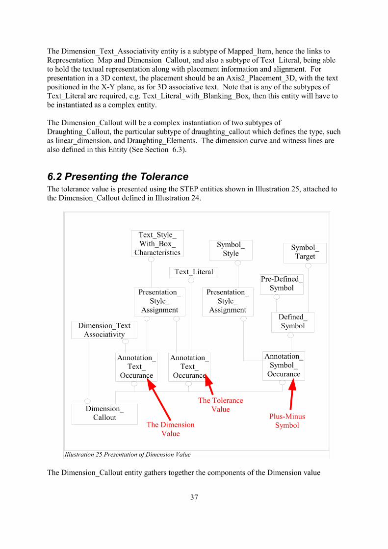
6.2 Presenting the ToleranceThe tolerance value is presented using the STEP entities shown in Illustration 25, attached tothe Dimension_Callout defined in Illustration 24.
The Dimension_Callout entity gathers together the components of the Dimension value
37
Illustration 25 Presentation of Dimension Value
Dimension_Callout
Dimension_TextAssociativity
Annotation_Text_
Occurance
Annotation_Text_
Occurance
Annotation_Symbol_
Occurance
Presentation_Style_
Assignment
Presentation_Style_
AssignmentDefined_Symbol
Pre-Defined_Symbol
Symbol_Target
Text_Style_With_Box_
CharacteristicsSymbol_
Style
Text_Literal
The DimensionValue
The ToleranceValue
Plus-MinusSymbol
string, i.e the value, the tolerance and the symbol separating them. The linkage of the valueback to the representation of the Dimension is done by attaching to the “Text_Literal” part ofthe Dimension_Text_Associativity entity. There is no equivalent linkage for the Tolerancevalue, although it is possible to navigate through the entities to pick up the true value. In fact,the entire Value and Tolerance string can be derived from the Representation, without theneed for the textual presentation entities. However, if the receiving system does not supportDimensional tolerances, then at least it can make use of the textual information to present iton the screen to the user.
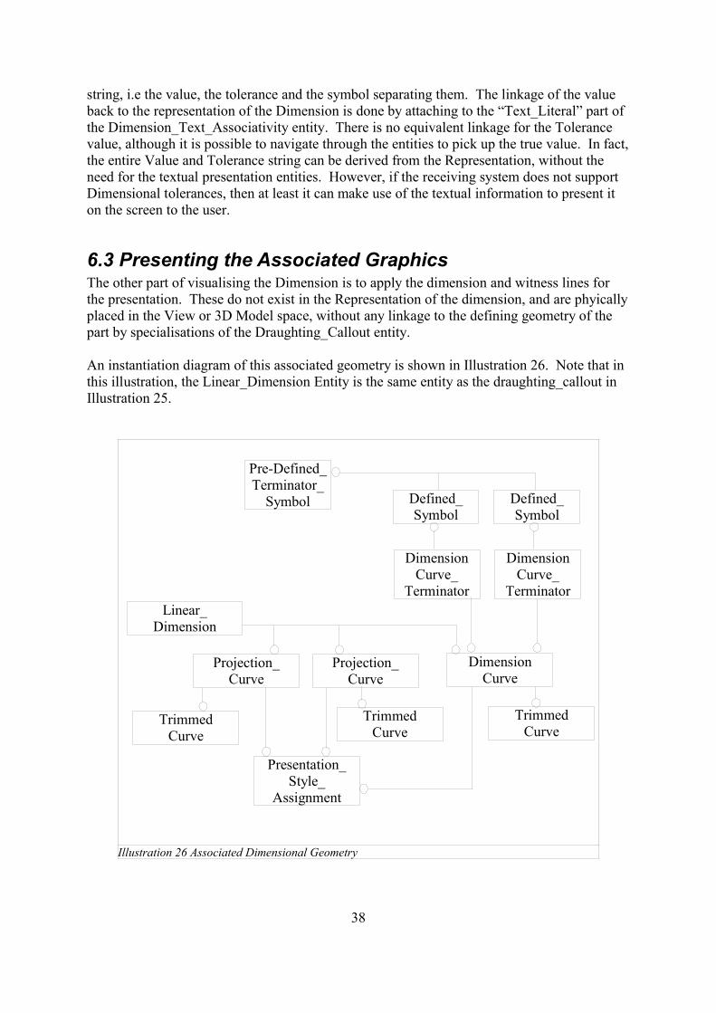
6.3 Presenting the Associated GraphicsThe other part of visualising the Dimension is to apply the dimension and witness lines forthe presentation. These do not exist in the Representation of the dimension, and are phyicallyplaced in the View or 3D Model space, without any linkage to the defining geometry of thepart by specialisations of the Draughting_Callout entity.
An instantiation diagram of this associated geometry is shown in Illustration 26. Note that inthis illustration, the Linear_Dimension Entity is the same entity as the draughting_callout inIllustration 25.
38
Illustration 26 Associated Dimensional Geometry
Linear_Dimension
Projection_Curve
Projection_Curve
DimensionCurve
TrimmedCurve
TrimmedCurve
TrimmedCurve
Presentation_Style_
Assignment
DimensionCurve_
Terminator
DimensionCurve_
Terminator
Defined_Symbol
Defined_Symbol
Pre-Defined_Terminator_
Symbol
7 Presentation of Geometric Tolerances
This sections deals with the presentation of Geometric Tolerances, and their attachment to therelevant “represented” GD&T information. This is very much a first pass as defining thisinformation and is heavily based upon the exchange of 3D Associative Text, as defined in“Recommended Practices for 3D Associative Text – Release 4 – January 13th 2000”, availableas a download from www.cax-if.de or www.cax-if.org .
It is envisaged that both this document and the 3D Associative Text Recommended Practiceswill evolve as further implementations of both come into being. The intent is to provide thisas a basis for further improvement, in such a way that the structures and methods definedform the basis for those improvements and are to be left as is, such that any files followingthese procedures are not rendered obsolete or unconformant in the future.
I would like to acknowledge the considerable input made to this section of Lothar Klein andGiedrius Liutkus of LKSoft Gmbh. Who have both put in a great deal of effort to lay thesefoundations and ensure future interoperability.
7.1 Geometric Tolerances as 3D Text The method for exchanging the Presentation of Geometric Tolerance Data is to leverage the3D Associative text capability developed in STEP and tested by the Cax-IF. The plus pointsof this approach is that either the Representation or the Presentation or both can be processedby a post-processor, depending on the capabilities of the receiving system. This means forfully intelligent systems, such as UGNX and CATIAV5, both the represented and presentedGD&T can be exchanged, whereas for viewing systems where the representation is notstored, such as JT, the data intent can still be exchanged.
In order to simplify the STEP files containing this data, some changes and enhancement toexisting STEP Modules will have to be implemented. This document will assume that thesechanges are already in place, but will draw the attention of the reader to them at theappropriate points.
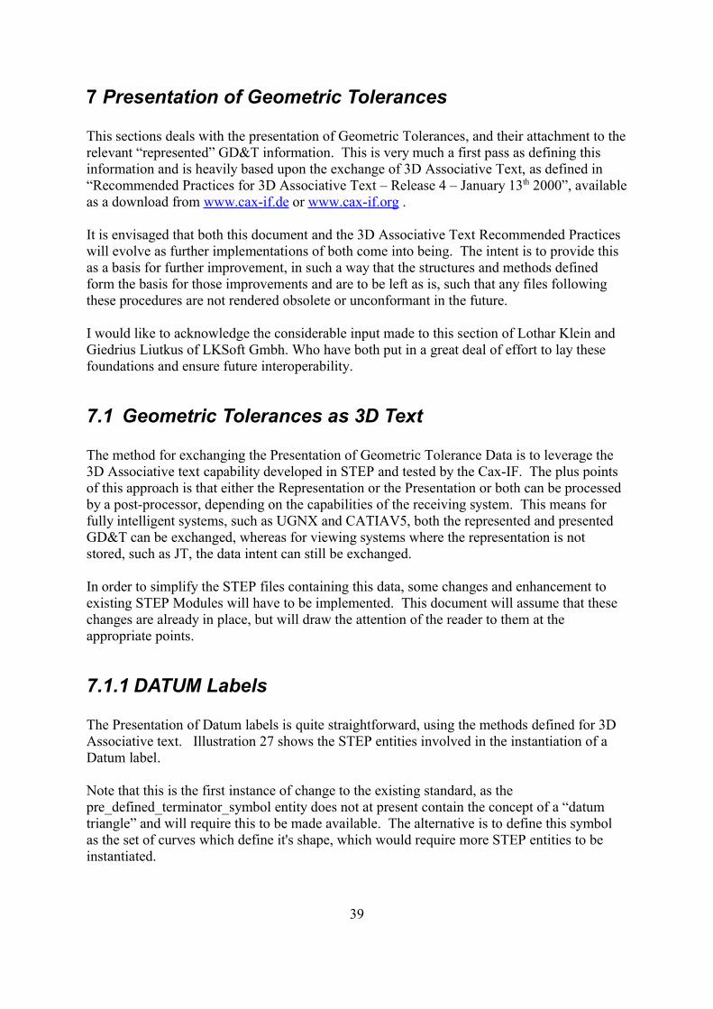
7.1.1 DATUM Labels
The Presentation of Datum labels is quite straightforward, using the methods defined for 3DAssociative text. Illustration 27 shows the STEP entities involved in the instantiation of aDatum label.
Note that this is the first instance of change to the existing standard, as thepre_defined_terminator_symbol entity does not at present contain the concept of a “datumtriangle” and will require this to be made available. The alternative is to define this symbolas the set of curves which define it's shape, which would require more STEP entities to beinstantiated.
39
In xxxx, the Leader_Curve entity is a complex instantiation of :annotation_curve_occurrenceannotation_occurrencedraughting_annotation_occurrenceleader_curverepresentation_itemgeometric_representation_itemstyled_item
This gives it the ability to style the leader curve as well as a link to the geometric curvedefining the leader in 3D space. The EXPRESS definition of annotation_curve_occurrencespecifies that the styled_item should be a curve. This would allow the leader line to be oneof the unbounded types of curve, which is meaningless. For implementations of thisfunctionality, it is required that the underlying geometric representation of the leader be asubtype of the Bounded_Curve entity. It is also suggested that this restriction beimplemented in the standards, perhaps as an additional restriction to thedraughting_annotation_occurrence entity in AIC 504, as this already contains restrictions forText and Symbols.
40
Illustration 27 Datum Presentation
Datum_Feature_Callout
Leader_Curve * Leader_Terminator *Annotation_Text_Occurrence *
contents
Curve Defined_Symbol
Symbol_Target
Pre_Defined_Terminator_Symbol
name = “open triangle”
placement
scale_xscale_y
item item
* Complex Entity
styles styles
The Leader_Terminator entity is also a complex instantiation, in this case of :annotation_occurrenceannotation_symbol_occurrencedraughting_annotation_occurrencegeometric_representation_itemleader_terminatorrepresentation_itemstyled_itemterminator_symbol
For the terminator symbol, it's position in the model is defined by the placement attribute ofthe symbol_target entity. What is currently unclear is how to define the size of the terminatorsymbol, as there is no mechanism to define a box size for the symbol as there is with text. Inorder to define this, which is a requirement for CAD systems, I suggest that the height andwidth of the symbol be stored in the scale_x and scale_y attributes respectively, defined in theunit system of the view on the model (e.g. as a ratio measure applied to “one” unit).
The annotation_text_occurrence entity is a complex entity, made up of :annotation_occurrenceannotation_text_occurrencedraughting_annotation_occurrencegeometric_representation_itemrepresentation_itemstyled_item
Where the item to be styled is the composite_text or text_literal.
One major problem from the viewpoint of GD&T presentation is the inability to simpledefine the box presented as a boundary around the Datum letter that is the text. One way ofdoing this is to define the text_literal as the text_literal_with_deliniation subtype. Part 46states that the AP can define the delineation types, and I propose that we use this for GD&T.In the case of a Datum, I would suggest a delineation of “rectangular frame”. This approachis in keeping with the approach taken within the CAD systems.
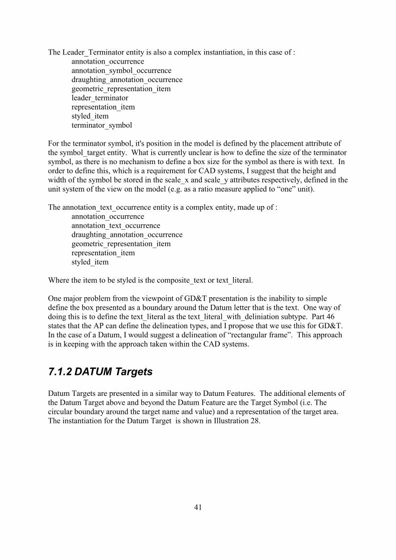
7.1.2 DATUM Targets
Datum Targets are presented in a similar way to Datum Features. The additional elements ofthe Datum Target above and beyond the Datum Feature are the Target Symbol (i.e. Thecircular boundary around the target name and value) and a representation of the target area.The instantiation for the Datum Target is shown in Illustration 28.
41
Depending upon the type of target area. The Datum_Callout Target will contain either anAnnotation_Point_Occurrence (for a point target), an Annotation_Curve_Occurrence (for aline target) or an Annotation_Fill_Area (for a rectangle or circle target area).
Similarly to the Datum Feature, the Annotation_Occurrence entities are instantiated ascomplex entities. Also the Text_Literal or Composite_Text styled by theAnnotation_Curve_Occurrence may have associated curves, defining the Datum TargetSymbol itself. Some CAD systems do not have access to these curves, and thus must makethe decision to draw the Target symbol based on the Callout type.
7.1.3 Feature Control Frames
7.2 Associating GD&T Presentation and Representation
The link between the Presented GD&T and the intelligent Representation is crucial. Thisgives the systems capable of handling the intelligent GD&T the information required both tomaintain the intelligence, and to place the presentation of that data on the screen for the userto see.
The method proposed for instantiating this relationship is the same method as used in 3Dannotation to associate the callout with a connection point on the geometry (i.e. Theassociated geometry for the text). This method defines a shape_aspect entity to contain the
42
Illustration 28 Datum Target Presentation
Datum_Target_Callout
Leader_Curve *Annotation_Text_Occurrence *
contents
Curve
item
* Complex Entity
styles
Annotation_Fill_Area_Occurrence *
Annotation_Curve_Occurrence *
Annotation_Point_Occurrence *
OR
OR
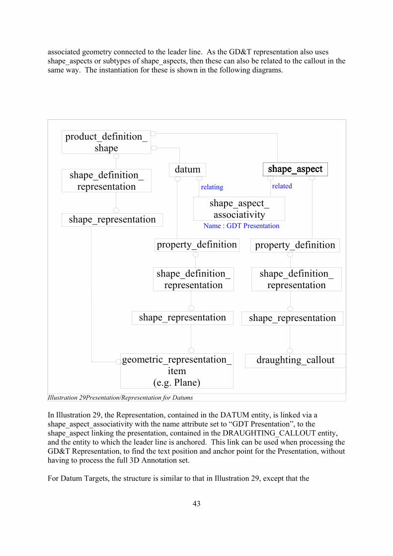
associated geometry connected to the leader line. As the GD&T representation also usesshape_aspects or subtypes of shape_aspects, then these can also be related to the callout in thesame way. The instantiation for these is shown in the following diagrams.
In Illustration 29, the Representation, contained in the DATUM entity, is linked via ashape_aspect_associativity with the name attribute set to “GDT Presentation”, to theshape_aspect linking the presentation, contained in the DRAUGHTING_CALLOUT entity,and the entity to which the leader line is anchored. This link can be used when processing theGD&T Representation, to find the text position and anchor point for the Presentation, withouthaving to process the full 3D Annotation set.
For Datum Targets, the structure is similar to that in Illustration 29, except that the
43
Illustration 29Presentation/Representation for Datums
datum
property_definition
shape_definition_representation
shape_representation
geometric_representation_item
(e.g. Plane)
product_definition_shape
shape_aspect
property_definition
shape_definition_representation
shape_representation
draughting_callout
shape_definition_representation
shape_representationshape_aspect_associativity
shape_aspectshape_aspectshape_aspect
relating related
Name : GDT Presentation
Representation shape_aspect subtype is Placed_datum_target_Feature, rather than Datum.
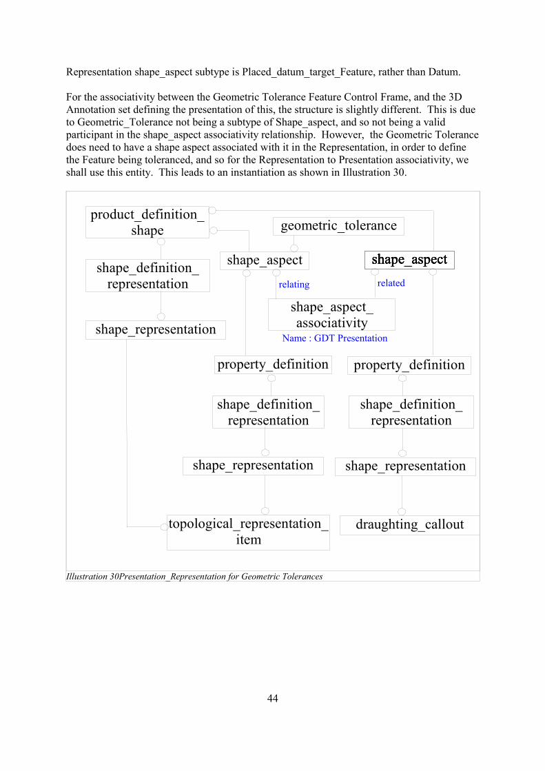
For the associativity between the Geometric Tolerance Feature Control Frame, and the 3DAnnotation set defining the presentation of this, the structure is slightly different. This is dueto Geometric_Tolerance not being a subtype of Shape_aspect, and so not being a validparticipant in the shape_aspect associativity relationship. However, the Geometric Tolerancedoes need to have a shape aspect associated with it in the Representation, in order to definethe Feature being toleranced, and so for the Representation to Presentation associativity, weshall use this entity. This leads to an instantiation as shown in Illustration 30.
44
Illustration 30Presentation_Representation for Geometric Tolerances
property_definition
shape_definition_representation
shape_representation
topological_representation_item
product_definition_shape
shape_aspect
property_definition
shape_definition_representation
shape_representation
draughting_callout
shape_definition_representation
shape_representationshape_aspect_associativity
shape_aspectshape_aspectshape_aspect
relating related
Name : GDT Presentation
geometric_tolerance
shape_aspect
8 Conclusions
In this Document, the practices for Representation of GD&T and the Representation andPresentation of Dimensional Tolerances is complete and implementable.
The Presentation of GD&T is based on 3D Annotation, which will require further work, notjust for GD&T, but also in order to to able to exchange annotations in general. This work willneed to determine a good way of encoding the GD&T presentation, as well as working uppractices for different 3D views on the model and associating the relevant annotation withthose views.
The resolution of these challenges is currently being undertaken by the Cax-IF, and it isenvisaged that the sandbox implementations that are done to prove out the proposed methods,will eventually become full blown production capability.
45