Fits, Geometrical...
32
Ahmed Kovacevic, City University London Design web Fits, Geometrical Tolerances Prof Ahmed Kovacevic Lecture 7 School of Engineering and Mathematical Sciences Room CG07, Phone: 8780, E-Mail: [email protected] www.city-design.tk www.staff.city.ac.uk/~ra600/intro.htm Engineering Drawing and Design ME 1110 – Engineering Practice 1
Transcript of Fits, Geometrical...
Ahmed Kovacevic, City University London
Design web
Fits, Geometrical Tolerances
Prof Ahmed Kovacevic
Lecture 7
School of Engineering and Mathematical Sciences
Room CG07, Phone: 8780, E-Mail: [email protected]
www.city-design.tk www.staff.city.ac.uk/~ra600/intro.htm
Engineering Drawing and Design ME 1110 – Engineering Practice 1

Ahmed Kovacevic, City University London
Design web
Objectives
• To learn how to effectively select
tolerance for parts so that these
function correctly i.e. to have
appropriate fits with parts in connection.
• To learn about geometric tolerancing
and surface finishing issues.
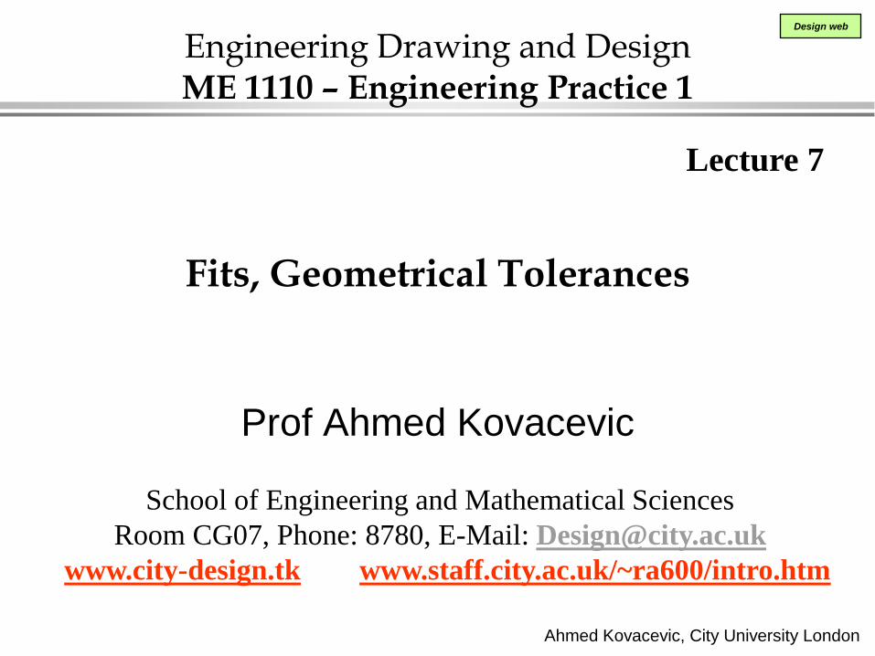
SHOW THE EXAMPLE DRAWINGS
Ahmed Kovacevic, City University London
Design web
Example detailed drawing
Ahmed Kovacevic, City University London
Design web
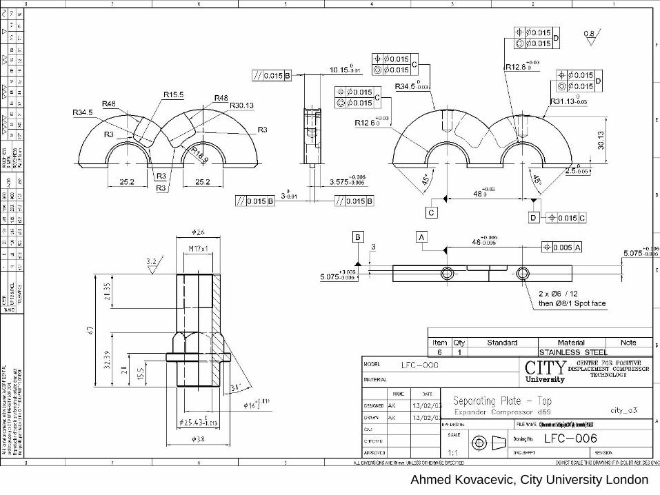
Fitting Two Parts
Part A
Tolerance of A Part B
Tolerance of B
Fit: Clearance or Interference
Ahmed Kovacevic, City University London
Design web
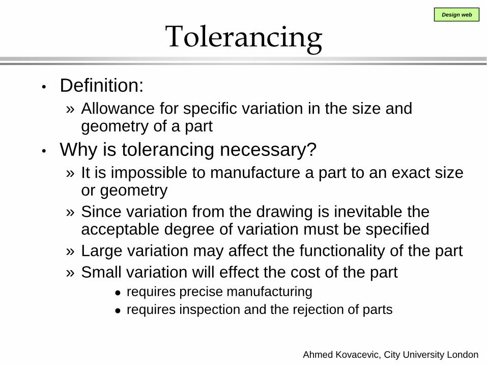
Tolerancing
• Definition: » Allowance for specific variation in the size and
geometry of a part
• Why is tolerancing necessary? » It is impossible to manufacture a part to an exact size
or geometry
» Since variation from the drawing is inevitable the acceptable degree of variation must be specified
» Large variation may affect the functionality of the part
» Small variation will effect the cost of the part requires precise manufacturing
requires inspection and the rejection of parts
Ahmed Kovacevic, City University London
Design web
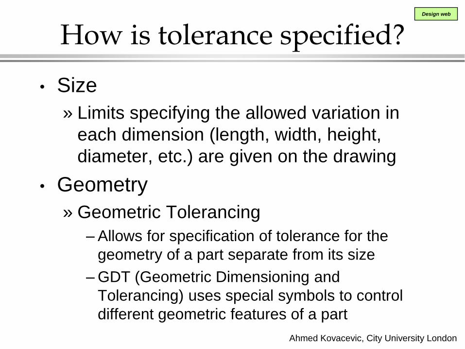
How is tolerance specified?
• Size
» Limits specifying the allowed variation in
each dimension (length, width, height,
diameter, etc.) are given on the drawing
• Geometry
» Geometric Tolerancing
– Allows for specification of tolerance for the
geometry of a part separate from its size
– GDT (Geometric Dimensioning and
Tolerancing) uses special symbols to control
different geometric features of a part
Ahmed Kovacevic, City University London
Design web
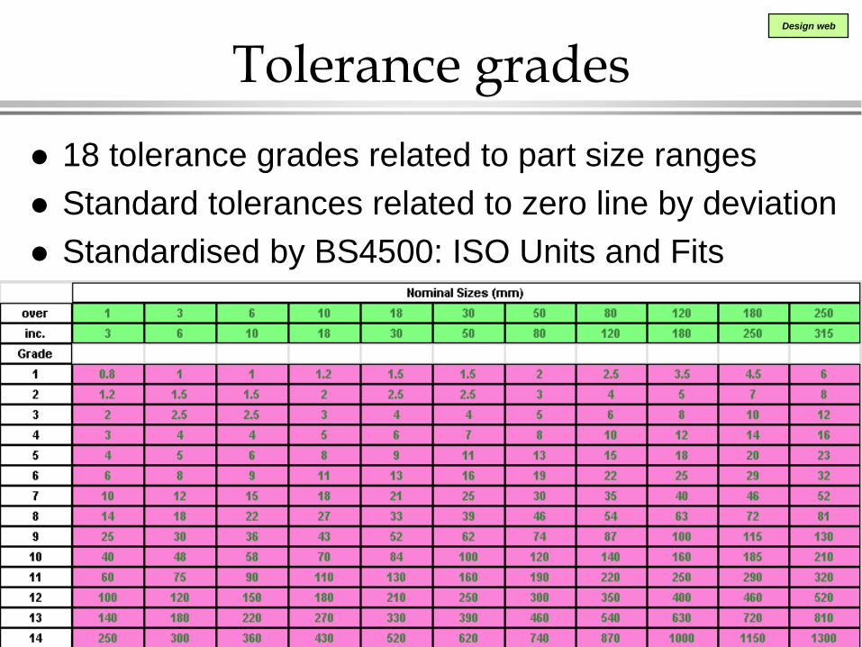
Tolerance grades
18 tolerance grades related to part size ranges
Standard tolerances related to zero line by deviation
Standardised by BS4500: ISO Units and Fits
Ahmed Kovacevic, City University London
Design web
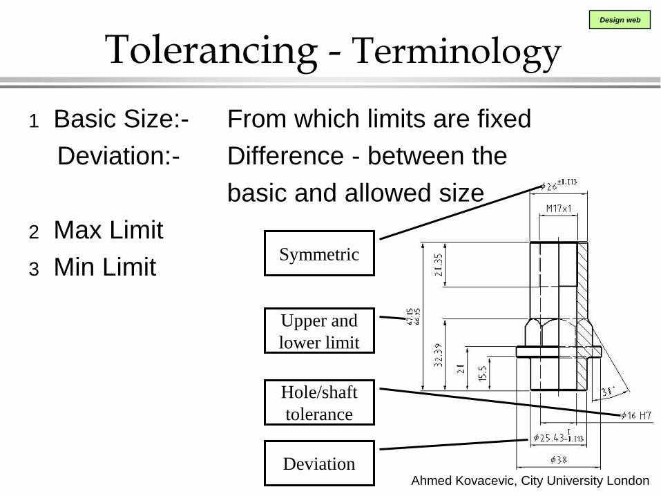
Tolerancing - Terminology
1 Basic Size:- From which limits are fixed
Deviation:- Difference - between the
basic and allowed size
2 Max Limit
3 Min Limit
Upper and
lower limit
Symmetric
Hole/shaft
tolerance
Deviation

Ahmed Kovacevic, City University London
Design web
Tolerance Terminology – continue
ZERO LINE 4
5
3shaft 2shaf
t
6
4
5
3hol
e
2hole 1
6
1 Nominal Size – a general size, common fraction
Basic Size – theoretical size from which limits are fixed
Actual Size – measured size
2,3 Limits – maximum and minimum permissible sizes
4,5 Deviation – max. and min. difference from a nominal
size (1-2 or 1-3)
6 Tolerance – total allowable variance in dimensions
(upper limit – lower limit or 2-3 or 4-5)
Ahmed Kovacevic, City University London
Design web
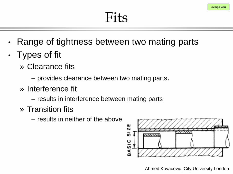
Fits
• Range of tightness between two mating parts
• Types of fit
» Clearance fits
– provides clearance between two mating parts.
» Interference fit
– results in interference between mating parts
» Transition fits
– results in neither of the above
Ahmed Kovacevic, City University London
Design web
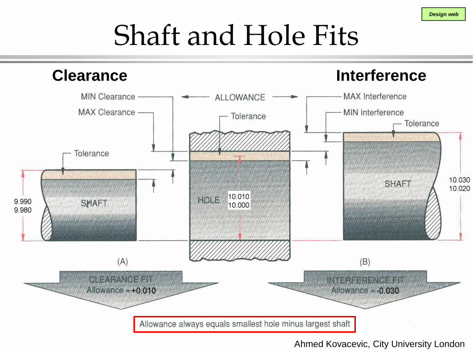
Shaft and Hole Fits Clearance Interference
Ahmed Kovacevic, City University London
Design web
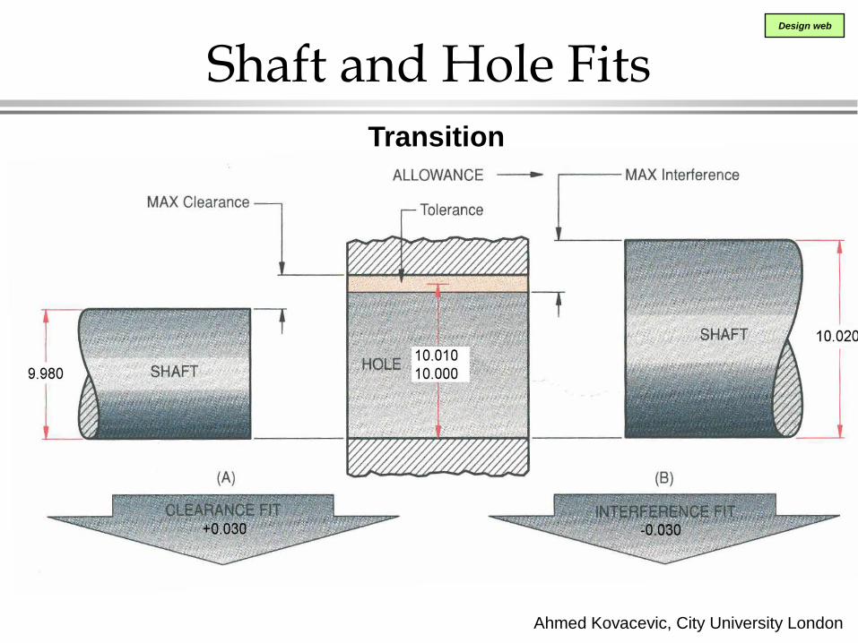
Shaft and Hole Fits Transition

Ahmed Kovacevic, City University London
Design web
Preferred Hole Basis System of Fits
Standardised by BS4500: ISO Units and Fits

Ahmed Kovacevic, City University London
Design web
Basic Hole System or Hole Basis
Definition of the "Basic Hole System":
» The "minimum size" of the hole is equal to
the "basic size" of the fit
Example:
If the nominal size of a fit is 10 mm,
then the minimum size of the hole in the
system will be 10mm
Ahmed Kovacevic, City University London
Design web
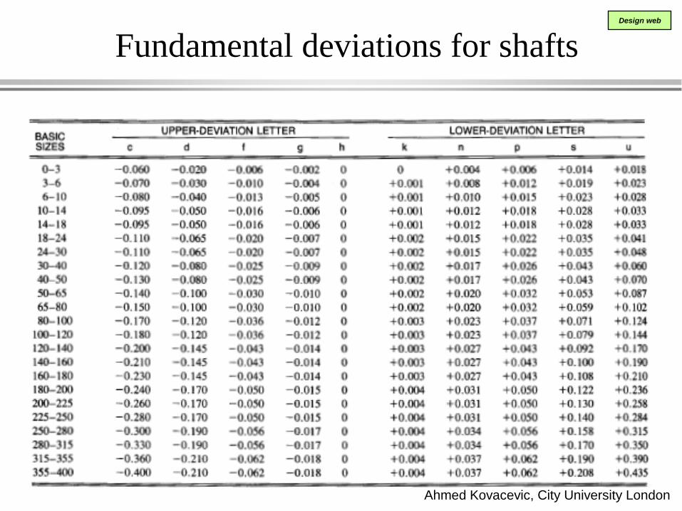
Fundamental deviations for shafts
Ahmed Kovacevic, City University London
Design web
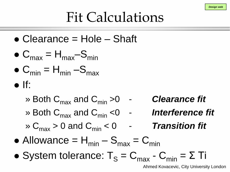
Fit Calculations
Clearance = Hole – Shaft
Cmax = Hmax–Smin
Cmin = Hmin –Smax
If:
» Both Cmax and Cmin >0 - Clearance fit
» Both Cmax and Cmin <0 - Interference fit
» Cmax > 0 and Cmin < 0 - Transition fit
Allowance = Hmin – Smax = Cmin
System tolerance: TS = Cmax - Cmin = Σ Ti

Ahmed Kovacevic, City University London
Design web
Example
ISO Tolerance
Grades
Fundamental
Deviations
0 +0.025 40.025 40.000 -0.009 -0.025 39.991 39.975
Max Clearance
Min Clearance
Allowance
System Tol:
Cmax=0.050
Cmin=0.009
= Cmin
TS =0.041
Homework
Ahmed Kovacevic, City University London
Design web
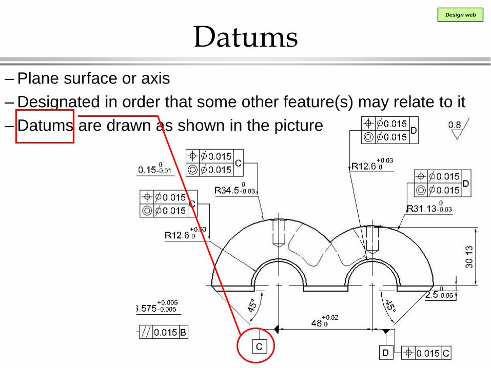
Datums – Plane surface or axis
– Designated in order that some other feature(s) may relate to it
– Datums are drawn as shown in the picture

Ahmed Kovacevic, City University London
Design web
Geometrical Tolerances
– Geometric tolerance of
a feature
(point, line, axis, surface)
specifies the
tolerance zone in which
the feature is required to
contain.

Ahmed Kovacevic, City University London
Design web
Notation Supplementary symbols
Tolerance frame variations

Ahmed Kovacevic, City University London
Design web
Tolerance examples
Flatness
Straightness
Ahmed Kovacevic, City University London
Design web
Tolerance examples
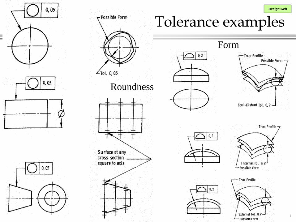
Roundness
Form
Ahmed Kovacevic, City University London
Design web
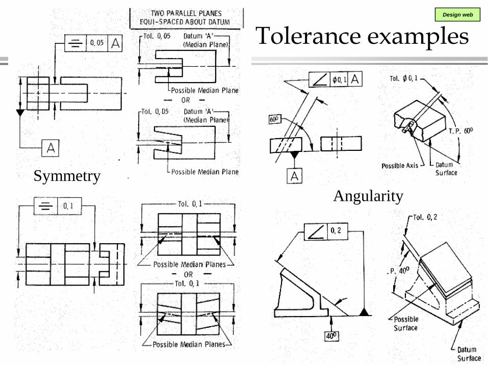
Tolerance examples
Angularity
Symmetry
Ahmed Kovacevic, City University London
Design web
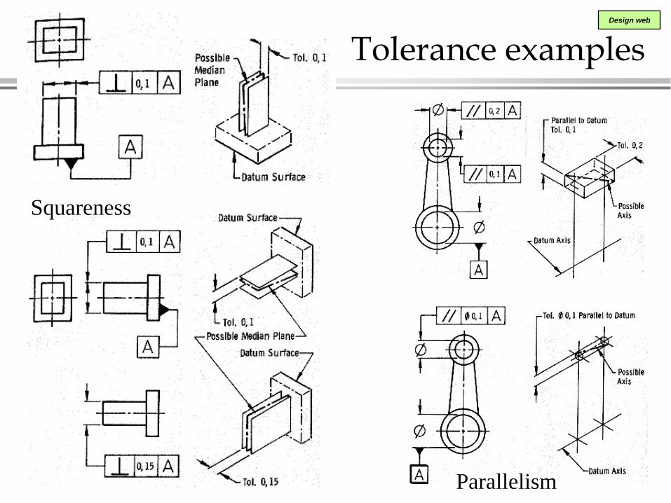
Tolerance examples
Parallelism
Squareness
Ahmed Kovacevic, City University London
Design web
Tolerance examples
Position

Ahmed Kovacevic, City University London
Design web
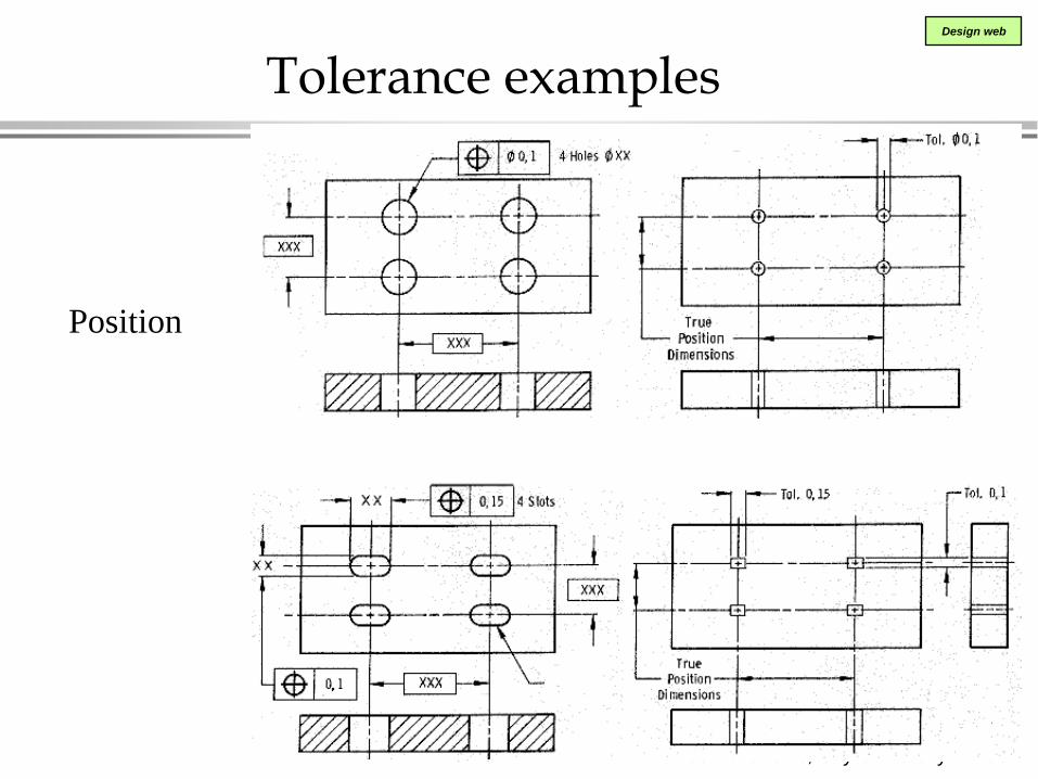
Tolerance examples
Position
Ahmed Kovacevic, City University London
Design web
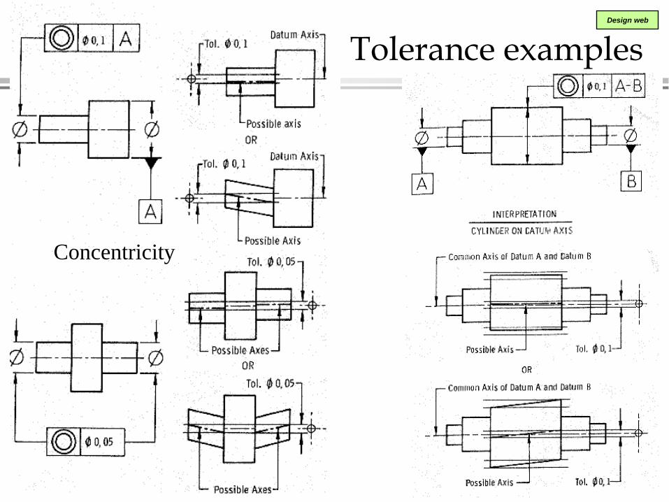
Tolerance examples
Concentricity

Ahmed Kovacevic, City University London
Design web
Tolerance examples Cilindricity
Maximum material condition
Profile tolerance
Ahmed Kovacevic, City University London
Design web
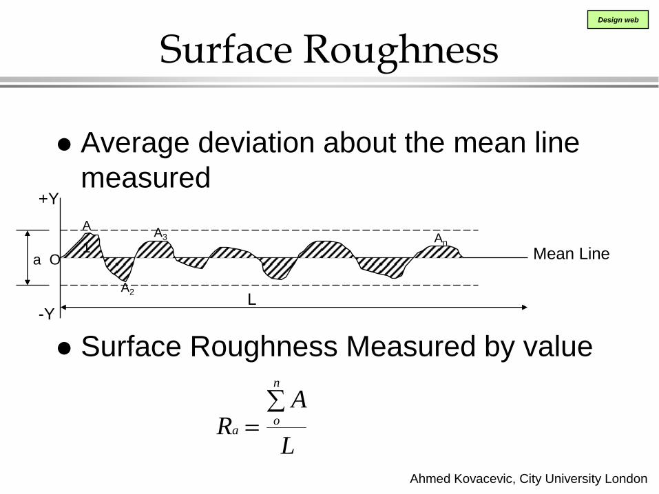
Surface Roughness
Average deviation about the mean line
measured
Surface Roughness Measured by value
a O
A
1
A2
A3 An
Mean Line
L
+Y
-Y
RA
La
o
n
Ahmed Kovacevic, City University London
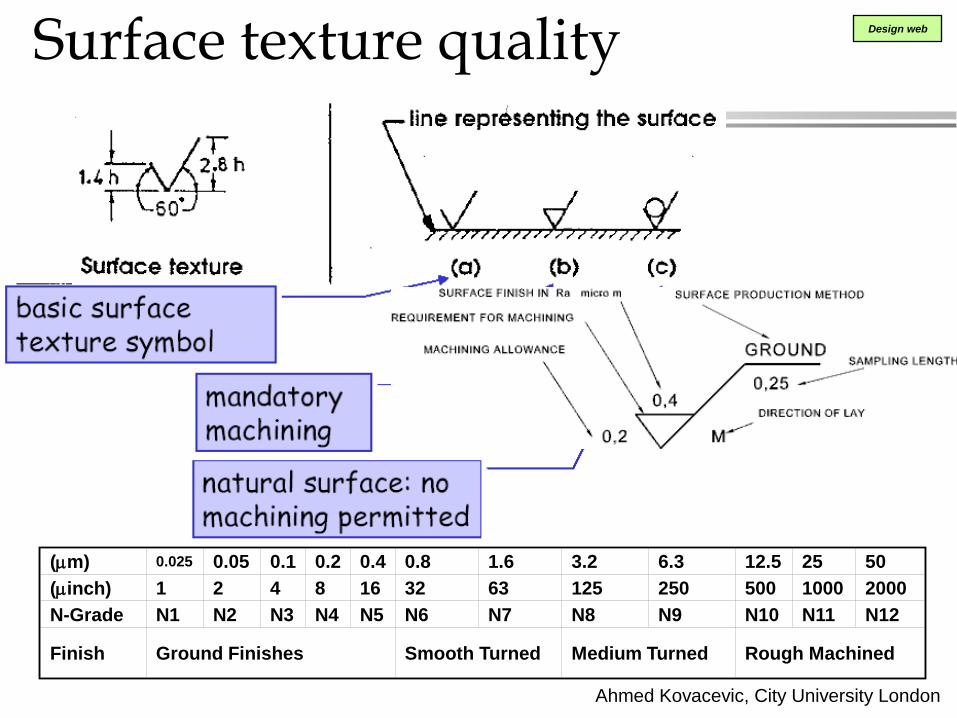
Design web Surface texture quality
(mm) 0.025 0.05 0.1 0.2 0.4 0.8 1.6 3.2 6.3 12.5 25 50
(minch) 1 2 4 8 16 32 63 125 250 500 1000 2000
N-Grade N1 N2 N3 N4 N5 N6 N7 N8 N9 N10 N11 N12
Finish Ground Finishes Smooth Turned Medium Turned Rough Machined

Ahmed Kovacevic, City University London
Design web
Manufacture methods and
roughness values

Ahmed Kovacevic, City University London
Design web
Exercise DrE-5
• Groups of 5. Each group has
one assembly with several parts.
• Measure parts in the assembly
together.
• Each member of the group will
have to do his/her own part.
• Make sketch - drawing with all
required dimensions, tolerances
and surface finish notes.
• This sketch has to be approved
and as such used as the basis for
CAD-1 exercise.
• 2 week exercise


![Final Report for AmeriCorps Opportunity Youth Evaluation ......[26 /xyz 70 448 0.00] [27 /xyz 70 445 0.00] [28 /xyz 70 720 0.00] [28 /xyz 70 483 0.00] [30 /xyz 70 420 0.00] [31 /xyz](https://static.fdocuments.us/doc/165x107/5f2350203f441e0a236e3614/final-report-for-americorps-opportunity-youth-evaluation-26-xyz-70-448.jpg)


![FINAL PERFORMANCE EVALUATION OF FEED THE FUTURE … · [19 /xyz 70 704 0.00] [19 /xyz 70 632 0.00] [19 /xyz 70 309 0.00] [20 /xyz 70 428 0.00] [22 /xyz 70 707 0.00] [23 /xyz 70 648](https://static.fdocuments.us/doc/165x107/5ebba31aef5660546f53bc1e/final-performance-evaluation-of-feed-the-future-19-xyz-70-704-000-19-xyz-70.jpg)