Recap: Registers A register is a single byte (or word) memory element. Once written to (clocked) it...
19
Recap: Registers A register is a single byte (or word) memory element. Once written to (clocked) it remembers the input byte and outputs the same number regardless of further changes at the D input… …until the next clock input of course. CLK D 0-7 Q 0-7 D 0-7 Q 0-7 CLK 8 8
-
date post
21-Dec-2015 -
Category
Documents
-
view
227 -
download
2
Transcript of Recap: Registers A register is a single byte (or word) memory element. Once written to (clocked) it...
Recap: Registers
A register is a single byte (or word) memory element.
Once written to (clocked) it remembers the input byte and outputs the same number regardless of further changes at the D input…
…until the next clock input of course.
CLK
D0-7 Q0-7D0-7 Q0-7
CLK
8 8

Interconnecting Registers
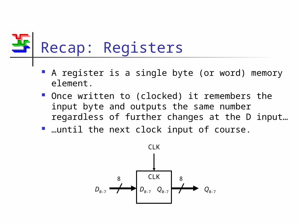
Interconnecting registers in a computer is like building roads to connect towns on a map:
Silly wayn towns require (n2-n)/2 roads
A
C
B
E
D
Interconnecting Registers
Interconnecting registers in a computer is like building roads to connect towns on a map:
Sensible wayFar fewer
roads, (but lesser
capacity)
A B
C
E
D

Interconnecting Registers
CLK
D0-7 Q0-7
CLK1
8 8
CLK
D0-7 Q0-7
CLK2
8 8
CLK
D0-7 Q0-7
CLK3
8 8
8

Register Connections
Data can be written from any register to any other register
Limitations Only one data transfer can happen at once In general, this is how computers work. They can only do a small number of very
simple operations… …and they can only do one of them at a time. But, they do it very quickly!

Bi-directional Connection
Connections from the common bus to the registers are bi-directional.
CLK
D0-7 Q0-7
8 8
CLK
Input / Output
8
Set of 8 digitally controlled switches
Input / OutputControl
Tri-State Ports
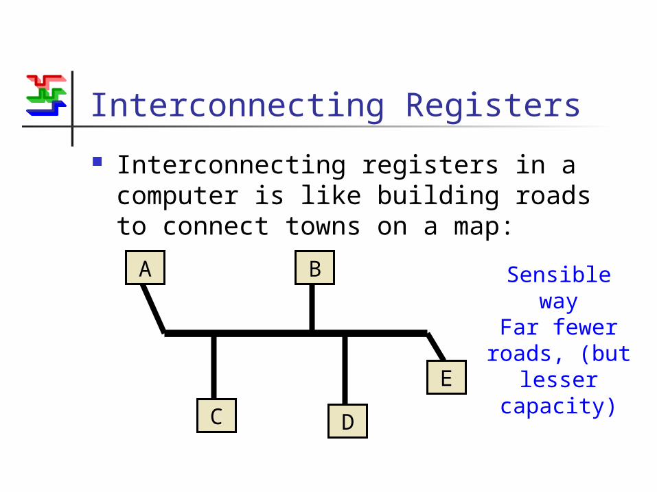
This arrangement is often known as a tri-state port.
Each input/output line can have three possible states: When being read from (input/output is low)
Low-Impedance, Logic 1 (or high) Low-Impedance, Logic 0 (or low)
Otherwise (input/output is high) High-Impedance (or floating, open-circuit)

Impedance
A simple switch can be thought of of having two states:
Low impedance (on) High impedance (off)
High impedance (tens of M)No current flows
Low impedance (tens of )Current flows

Equivalent Circuits for Tri-State Port
Low Impedance Logic 0
(Low)
High Impedance
Low Impedance Logic 1
(High)
+5 V
0 V
+5 V
0 V
+5 V
0 V
I/OI/O I/O
Three ports sharing a common bus.
Port 1 is in the high state, ports 2 and 3 are in the high impedance
states.
+5 V
0 V
I/O1 I/O2 I/O3

What NOT to do…
Three ports sharing a common bus.
Port 1 is in the high state, ports 2 is in the high impedance
state, port 3 is in low state.
Current
Only one port can be in a low-impedance (output) state at any time
+5 V
0 V
I/O1 I/O2 I/O3

Tri-State Ports and a Common Bus
Only one register can be read from at a time.
i.e. all tri-state ports except one must be high-impedance.
Any register can read and store the contents of any other.
A I/OCLK
I/O
8
CLKA
I/OA
CLKB
I/OB
CLKC
I/OC
SystemBus
B I/OCLK
I/O
C I/OCLK
I/O
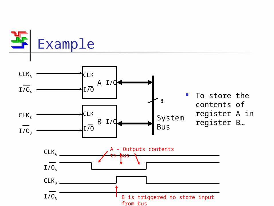
Example
To store the contents of register A in register B…
8
CLKA
I/OA
CLKB
I/OB
SystemBus
CLKA
I/OA
CLKB
I/OB
A I/OCLK
I/O
B I/OCLK
I/O
B is triggered to store input from bus
A – Outputs contents to bus

Simplifying the ALU with a Bus
ALU
A B S
COUT F
Single input byte
Control inputs
Result Carry output
Working register
D Q
CLK 8
8
Before8 data input lines
8 data outputs
ALU
A B S
COUT F
Control inputs
Carry output
Working register
8
8
8
Bus
AfterOne set of 8 shared data input/output
lines
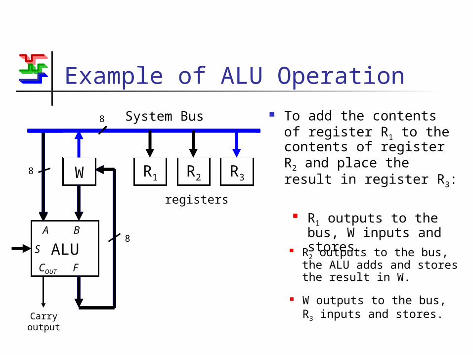
Example of ALU Operation To add the contents of
register R1 to the contents of register R2 and place the result in register R3:
W R1 R2 R3
System Bus8
registers
ALU
Carry output
A B
S
COUT F
8
8
R1 outputs to the bus, W inputs and stores.
R2 outputs to the bus, the ALU adds and stores the result in W.
W outputs to the bus, R3 inputs and stores.

ALU Operation Notes
Although the ALU performs calculations instantaneously (nearly), this addition requires three separate operations
However, it is now possible to perform ALU operations on any pair of register contents
Despite this flexibility, the required connections are relatively simple

Automating the ALU To perform calculations like the previous
example, the following control signals must be generated in sequence:
Input / Output select signals to the registers Clock (latch enable) signals to the registers Selection inputs to the ALU
To perform a predetermined set of operations, the corresponding sequence of control signals must be stored.
This is called a program.

A Victorian Computer Control signals = piano key
presses Sequences of key presses are
stored as holes on a paper roll. This is exactly how early
computer programs were stored too.
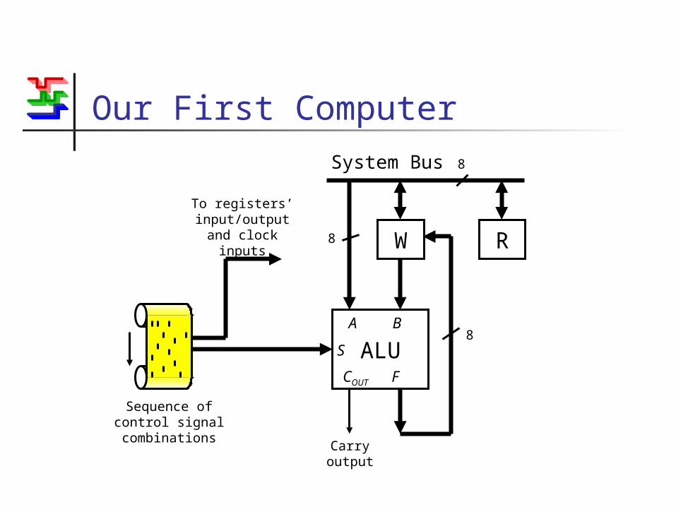
Our First Computer
W R
System Bus 8
ALU
Carry output
A B
S
COUT F
8
8
To registers’ input/output
and clock inputs
Sequence of control signal combinations

Summary The use of tri-state ports and a common
system bus hugely simplifies register interconnections.
With an ALU and a few registers, relatively elaborate operations can be performed.
The necessary control signals could be recorded for automatic operation.
Of course, we don’t really use paper tape. Instead we use program memory.