re A Practical TELEVISION - americanradiohistory.com · TV TURRET TUNERS, button models 19/6. P....
52
re A `Wmtl%sk Practical TELEVISION 2'
Transcript of re A Practical TELEVISION - americanradiohistory.com · TV TURRET TUNERS, button models 19/6. P....

re A `Wmtl%skPracticalTELEVISION
2'

PRACTICAL TELEVISION October, 1967
17in.-f11.10.0 TWO-YEAR GUARANTEE3 Star Guarantee* Tube * Valves . EX -RENTAL TELEVISIONS
* Components Carr. 30'.
COCKTAIL STEREOGRAM
....S ...x
i
TRANSISTOR CASES64" x 31". P.6 P.4/6. SimilarSINGLE PLAYER CABINETSTV TURRET TUNERS,button models 19/6. P.
CABINET £25Polished walnut veneer with
- elegant glass fronted cock -compartment, padded
position for two 10In. ellip-tical speakers. Record stor-age space. Height 35(in.,Width 521in., Depth 144in.
sk Legs 1 gn. extra.Other models. Send forfree list.
TAPE RECORDERCABINETS 498. Die. 16" x124" x W. Red and Grey. Cutout for BSR deck. P. & P. 7/6.
19:6. Cloth covered many colours. Size W xcases in plastic 7/6.
19/6. P. & P. 7/6.29I. New, less valves. Slim models 5/-. Press
& P. 4;6.
FREE ILLUSTRATEDLIST OF TELEVISIONS
17" -19" -21" -23"WIDE RANGE OF MODELS
SIZES AND PRICES- DEMONSTRATIONS DAILY....m..- - -TWO-YEAR GUARANTEEDTUBES 100% REGUNNED
141n.-119/6 171n.-89/621in. and all SLIMLINE TUBES 99/6Exchanged Bowls Carr. 10/6
EX MAINTENANCE -4.1.TESTED TUBES
17111.-35/. 14in.-15/..Carr. 5/- (not slimline)
DUKE Et CO. (LONDON) LTD.621/3 Romford Road, E.12 (Parking space) ILF 6001-2-3
BI-PRE-PAK LTD222-224 WEST ROAD. WESTCLIFF-ON-SEA. ESSEX
PHONE: SOUTHEND ,0302) 46394
NEW FROM THE U.S.A."TEXAS" Integrated Circuits
S N7360 Quadruple 2 Input 19/6Nan.UNor late,AI,SN7430 s lima. P",itive
Nand Gate. 21/6S N7302 Dim! I -K Flip -Flop 35/-with Preset.
F.E.T.'s Field Effect Transi.t.rrs
2N3822 .S I 'flannel 4 -Lead 15/-'
Transistors PriceAF114
.... 4/-
21,1:,.: .... ,_
AFH7 41I In .... 3/6
AEI 19 .... /6AFITS ....10/-lisY115A . . 5/0
-- /-
1.1C2]1 un-OC200C2ti
815/-
( 25'O:15/5/
04'4 I 2/60012 2/60(.71ei '72
2/62/6
01'72 5/01, I 2/6Of ',ill. , . 2/60,,.3 4/
01'139 .. 2/640011 ..
Orl70 .. 5l -DI .. 4/-01.1041 .. 5/ -012111 .. 8/-o1 Y194" 4/ -
9]497 5/-2N7116 5/-2N 12112 . r 2 4/-
2N loll ..r 3 5/-2N I :MO or 7 6/-2X 1209 or 9 Si-
FANTASTIC! BARGAINS* OF THE YEAR *,,,
0C45 IF transisti* l iv0C44 0..c. I ran Attor 1/11OAS Equal to 0A5 2_0C36 Power transist..r
(er than 0C33)7/6
bett
GENUINE TRANSISTORS NOT REMAKES
N... PRE-PAKK PRICEAl. 6 -Silicon recliners 11Y 1 00 type 20/-.42. 10 -Relays mixed types and voltages 20/-
.93. 241 Mixedmarked and tested trans 20/-
141. 50-1'nmarked, untested, trans., new 10/-1132. 30 -Trans., new tested, but 1111111.k011 10/- ALL OUR SEMICONDUCTORS HAVE A WRITTEN GUARANTEE Send for our FREE lists and catalogne of all 'or products. Check y.oir .own...iiiivalitti with inor free substitution chart.FIRST EVER 1,01111' K ITS. ',rani for yourself how computers work. evenmake one for yourself. Frill Instructions for a noughts and crosses machine,Iduary counters, timer* etc. L.1 5 gas. L.210 gni. NO need to parch.... bothkits, you can start with 1,2, which incorporates L.I. DETA I 1,0 FREE.NO CONNECTION WITH ANY OTHER FIRM. MINIMUM OR DER10/-. CASH WITH ORDER PLEASE, aild I/- post and packing.
OVERSEAS ADD EXTRA FOR AIRMAIL.
A FULL -FEATURE TM FOR
THE SERIOUS ENTHUSIAST
Plus a 0.5V scale4=3
for transistor servicing= Kits have never looked this good before, never hadI. such a professional finish because ICnightkits have
never been widely available in the U.K. Now theyare -from Electroniques.
limy The KG 625 Vacuum Tube Voltmeter kit costs£28.19.6d. and is just one example of the high -qualityrange of test equipment -'scopes, signal generators.multimeters, power packs etc. that are covered inthe FREE 70 -page Knightkit brochure. We put thequality in -you build it up. It's instructive and kitbuilding saves you money.All kits are fully guaranteed and available on credit
ulna terms if required.Knightkit doesn't only mean test gear, but Hi-Fiand photographic equipment, and electronic car
IiII tuning kits as well. In fact there's a Knightkit forevery interest.Features of the KG 625 6in. 200p.A meter: movement
laml shorted in "off" position: fluorescent knife-edge=IN pointer; pre -aged bridge valve and matched triodeQsection; separate colour scales; direct reading= peak -
to -peak a.c. volts; gimbal bracket mounting; sup-plied with battery and test probe. R.F.demodulator and probe also availableas accessories.
1111 Use the coupon on the right to get therest of the facts on the completeKnightkit range.
I am interested in the KG 625 VTVM andshould like to read further details in yourFREE brochure K3.Send to Electroniques (Prop. STC) Limited,Edinburgh Way, Harlow, Essex.
NAME
ADDRESS
knight -kit byQuality Built-in Built-up by you electroniques
October, 1967 PRACTICAL TELEVISION
AN IMPORTANT ANNOUNCEMENT TO THE MANYTHOUSANDS WHO HAVE BOUGHT AND WILL BUY
The COMMON CORE SeriesCOMMON -COST
there is now added
THE 'NUMBERS GAME'Play it with TRAINER -TESTER Response Sheet No. E3 and the eleven
ADJUNCTIVE PROGRAMMING SUPPLEMENTS TO
basic electricity andbasic electronics
Full details and prices will be sent on application to
THE TECHNICAL PRESS LTD112 WESTBOURNE GROVE, LONDON, W.2
* Incidentally BASIC TELEVISION part 1 is now ready (see be/ow)
pascitYtolec
Agogrs
1116918 1051
10)
f..,;;;*
SPECIALANNOUNCEMENT
The New Picture-Book'way of learningBASICELECTRICITY (5 vois)ELECTRONICS (6voLs)
You'll find it easy to learn with this outstandinglysuccessful new pictorial method-the essentialfacts are explained in the simplest language, oneat a time: and each to Illustrated by an accuratecartoon -type drawing.
-NOW READY-
BASIC TELEVISION Pt. 1.Price 22/- inc. postage
Complete in two parts, publication date of Pt. 2 tobe announced later. Available on 7 days free trial,see coupon.
The books are based on the latest research intosimplified learning techniques. This has provedthat the Pictorial Approach to learning is thequickest and mutelest way of gaining masteryover these subject,.
411M11111111111111111111111111111 MII IS NI IS
TO SELRAY BOOK CO.60 HAYES HILL, HAYES, BROMLEY, KENTPlease send me Without ObligatiOn to Purchase, one of the above sets on 7 Days FreeTrial. I will either return set, carriage paid, in good condition within 7 days or seat.the following amounts. Basic Electricity 70/, Cash prier or Down Payment of ip/-
Mg followed by 4 fortnightly payments of 15/- each. Basic Electronics 82/-. Cash M:faor Down Payment of 15/- followed by 5 fortnightly payments of 15/- each. TO
IIoffer applies to U.K. only. Overseas customers cash with order.Tick set required lastly ONE set allowed an free trial).
BASIC ELECTRICITY 701- BASIC ELECTRONICS M. 0BASIC ELECTRONIC CIRCUITS 40/ -BASIC INDUSTRIAL ELECTRICITY 40/ -BASIC SYNCHROS & SERVOMECHANISMS M.BASIC TELEVISION PART 1 22/-
Signature
NAME
LL AU prices include postage
PRO
(If touter 21, signature of parent or gtta,dOl*
FULL POSTALADDRESS
BLOCK LETTERS BELOW

2 PRACTICAL TELEVISION October, 1967
This is the latest list of Line OutputTransformers and Inserts from D 8 B
TelevisionNOW UNDER NEW MANAGEMENT
ALBA Prices on request.BUSH TV53, TV56, TV57, TUG58, TUG59,
M59, TV63, TV66, TV67. Inserts 27/8.Other types rewind at 70/-.
DECCA DM3, Exchange unit 70/-.EKCO TC208, TC209, TC209/1, T221 to 331.
Complete LO.P.T. 40/-. TMB272 48/6.T344, T344F, 1348, 7348F, T356, TC312,T313, T313F T335 58/6.
EMERSON E700, E701, E704, E707, E708, E709,E710, E711, Portarama, Inserts 35/-.
FERGUSON 306, 308 40/-. 204 to 246, Inserts 30/,FERRANTI 14T2 to 14T5,17K3 to 17SK4, Inserts 35/-.
T1001, T1002, T1002/1, T1004, T1005,T1021, T1011 40/-. T1012, 11023,T1034, T1022 58/6.
K.B. PV40, MV100/1, OF100, PV100, NV40,NF70, OV30, QV10, QV30, Inserts only45/- pair. All other types rewind 70/-.
PETO SCOTT TV1416. TV1419, TV1716, TV1719,TV1720, TV1722, TV1725, TV1418,TV1726, Inserts only 32/6.
PYE V4, V7, VT4, VT7, CTM4, CTM7, Insertonly 40/-. V200, V400, V210 55/-.Other types prices on request.
PILOT V110, 117U, Inserts only 30/-.REGENTONE 114, 10-6, 10-4, 10-17, 10-21, Inserts
only 30/, 1176, 191, 192, T21FM,Inserts only 45/-. Deep 17, THE17, T21,600, 590, Inserts only 35/-.
SOBELL T25, T280, 193, SC24, SC34. SC370,T279. TPS186, Rewinds only 70/-.
All the above L.O.P.T. can be rewound at 70/-.
ULTRA 1984, 1984C, 200C, Rewind only 70/-.
1967 REVISED VALVE LISTCBL31 14/- EF184 6/3DAF91 4/3 EL84 4/2DAF96 6/3 EM81 6/9DF91 3/- EY51 6/10DF92 3/- EY86 6/3DF96 6/11 EZ81 4/11D K92 7/9 PC86 10/9DK96 6/9 PC88 10/9DL94 5/9 PC97 7/3DY87 6/3 PCC84 5/6EABC80 6/3 PCC89 10/ -EB91 3/- PC189 10/10EBC90 4/3 PCF80 6/2EBF89 6/6 PCF82 7/7ECC82 4/9 PCF86 7/9ECH42 9/3 PCL82 7/-ECH81 5/- PCL83 8/6ECL80 6/9 PCL84 7/6ECL82 6/3 PCL85 8/11EF80 4/9 PFL200 13/6EF85 6/3 PL36 10/6EF183 6/- PL81 7/6
PL83PL84PL500PY33PY81PY82PY800PY801UABC80UCH81UCL82U25U2630C1530F530FL130L1530P1230P1930PL130PL1330C18
6/66/6
13/68/66/-5/66/-6/-5/36/37/-
12/312/311/3
9/913/914/98/1112/914/914/910/ -
All Line Output Transformers, Inserts and Valvesare new and are fully guaranteed for 3 months.C.O.D 5/- extra. Return of Post service.S.A.E. all enquiries. Post and packing 4/6.
D. Et B. TELEVISION (Wimbledon) LTD131 KINGSTON ROAD, WIMBLEDON,01 540 3513 S.W.19 01 540 3955
"SABRINA"STILL WELL IN
FRONT
COMPLETELY REBUILT C.R. TUBESALL TYPES12" now .. £5. 0.01
For14" to 17" now .. £5.10.019" now .. £6.15.01 Single
Tubes21' now .. £8. 0.0ALL C.W.O.-TRADE SUPPLIED
Special Bonus Scheme for ServiceEngineers-Reducing to:
12"-87/6; 14"/17"-97/6; 21 "-147/6FREE Pass. transit 8- Ins. anywhere inBritish Isles or N. Ireland (12 months'
guarantee).
ALSO FULL RANGE OF VALVES(Guaranteed 12 months)
SABRINA C.R. TUBE CO.Electron Works, 50 North Bar
BANBURY, OXONTelephone 2390
VALVES SAME DAY SERVICENEW! TESTED! GUARANTEED!
SETS 4!?1842;o1;r111/390.41`F'1;6!411: DF91, t9,16°11.VarA7(;T 7/6 7117 7/- DAC32 7/3 ECL80 6/- PC900 7/9 T1121C 11/
11150T 7/8 703 12/- D.4.991 5/9 ECL82 8/8 PCC84 5/6 025 11/6N5GT 7/9 708 8/9 DAF96 8/- 501.86 7/9 PGC89 9/9 U26 11/6
1R5 5/6 7H7 5/6 DC(190 7/- EF39 8/9 900189 8/6 U47 17/6184 4/9 7Y4 8/6 DF33 7/9 EF41 9/8 PCF80 8/6 U49 18/643 3/9 10E1 9/9 DF91 2/9 3080 4/9 PCF82 8/- 1,02 4/6
ITS 2/9 10913 10/6 DF96 6/- 3085 5/- PC086 9/- U78 8/6sA5 7/- 12AT7 3/9 DE177 4/- 0186 C.' P0080010/6 0191 11/6Q4 5/6 12AU6 4/9 D1is1 12/6 3E89 5/- PC1801 8/9 1,301 13/-84 4/9 12AU7 4/9 131132 7/9 9E01 8/6 P00802 9/8 0801 18/-
1V4 5/8 12AX7 4/9 DKil 1 5/5 3E92 8/8 900803 9/9 UABC80 5/50433 4/8 121(stiT 7/6 DK92 8/- E197 7/6 PCF8013 11/6 UA942V4G 7/9 2011 11/8 DK96 8/8 3E183 6/8 PCF 80811/3 UB41 6/6Y3OT 6/- 201.1 14/8 D1.33 8/9 31,184 5/9 PCL82 6/9 UBCA1 6/9240 7/8 2091 9/- DL35 6/- 51190 6/8 PCL83 8/8 UBF80 6-
6/301.2 11/9 2093 14/9 DL92 4/9 31.33 6/8 PCL84 7/- UBF89 5//96A1.5 2/8 2094 17/- DL94 5/6 EL4I 8/8 #01.83 8/3 U BL21 9/-'Al.16 3/6 23U4GT11/8 01.96 6/- EL84 4/9 P01.08 8/6 U 5/-'A343 4/9 11815 11/6 DY86 5/9 01.90 5/ - PENA4 8/9 U CC84 79OATS 4/- 30017 12/6 DY87 5/9 31,93 5/- PEN311C16/- UCC85 8//13'13A0 4/6 30018 11/9 EABC80 6/- EM80 5/9 PFL20018/6 UCF80 833E6 4/3 10E3 12/- EAF42 8/6 EM81 6/9 PL36 9/- UCH21 9/8BGIiG 1.5/- MIL] 13/9 31301 2/8 EM/14 8/3 91.81 6/9 UCH42 8/9
611J6 8/9 OFL14 12/6 EBC33 7/- 5587 6/6 P1.82 6/6 UCH81 8/-BW6 7/3 301.15 12/- EBC41 8/- EY51 6/9 PL83 6/3 CCM 7/-CS6 6/6 30L17 13/- EBF80 7/- EY86 6/- PL84 6/8 UCL83 8/991 7/9 8094 12/- 313E89 5/9 5140 8/9 91.500 18/8 17F41 8/-F13 3/6 30912 11/- ECC81 8/9 EZ41 6/9 PX25 5/9 UF80 7/-F14 9/- 30919 12/- ECC82 4/9 EZ80 4/8 9Y32 8/8 UF89 5/9122 12/8 3OPL1 14/6 ECM 7/- EZ81 4/6 PY33 8/6 UL4I 8/9K733 1/6 30PL13 14/6 ECC84 8/8 GZ32 9/- PY80 5/8 UL44 20/-K8G 4/3 3091.14 14/8 ECC83 5/6 KT8 6/6 PY81 5/8 UL84 6-K6GT 7/6 331.11GT 7/6 ECF80 7/- 12/- PY82 5/- UY21 8//9
8Lis 0/- 33104 4/8 ECF82 8/9 X18 5/6 P Y68 5/9 tf 41 5/6Vtili 3/8 35Z4GT 4/8 50086 9/- N78 14/9 PY88 7/8 UY85 4/9V//UT 8/8 0003 12/6 501135 8/- N106 13/6 PY800 9/- VP4B 10/6X4 3/8 AZ31 9/- ECH42 9/- PC86 8/- PY901 6/- 1791321 21/-X3GT 0/9 3311 4/9 ECH81 6/8 PC88 8/- 1019 7/- W77 3/3
786 10/9 B729 12/6 1I1,384 8/6 PC97 5/9 R20 12/9 177 8/6
READERS RADIO85 TORQUAY GARDENS, REDBRIDGE
ILFORD, ESSEX. 01-550 7441Postage on 1 valve 9d. extra. On 2 valves or more Mi. per valve extra,
Any parcel moored against damage in transit 6d. extra
Practical TelevisionINTERIM PERIOD
LAST month we posed the question of where are thecolour sets. Well, we saw some of them during ourBaedeker tour of London hotels which housed therecent series of trade exhibitions (described elsewherein this issue).
An impression gathered was that colour TV wasnot always given the expected brass band treatment.Moreover, it seems more than likely that the BBC,too, is playing the colour scene very coolly duringthis launch period.
The reasons could be that manufacturers, due tocapital risk in setting up production lines, the dangersof over -production and the technical complexity ofthe final product, would prefer to phase in productionon a slowly rising scale rather than go all out formaximum initial impact. Such reasons may beeconomically sound, even essential, but the viewingpublic will not have their interest kindled, nor theirconfidence gained, when sets are in such short supplythat most dealers do not yet seem to have either theinitiative or the ability to obtain demonstration modelsfrom the makers.
But even though colour is so very slow in makingheadway at the moment, it could really get under waywhen enough sets roll off the assembly lines, when theBBC starts the full service and when the industrygenerally is seen to be enthusiastic. In this interimperiod, however, most service technicians have availedthemselves of training courses organised by'set makersand institutions and have studied articles in this andother technical journals. But very few have actuallybeen faced with a genuine faulty receiver-yet!
In the event, colour servicing may not be so daunt-ing, for detailed analysis will often be unnecessary.Makers are building their sets on the unit panelprinciple, enabling the substitution technique to beused to restore operation. And one will not need muchnew test equipment, apart from a cross hatch genera-tor (even without colour facilities), a degaussingdevice and something to measure up to 25kV.
We will, in due season, carry articles on colourservicing. In the meantime, brush up your theory andtry not to feel too alarmed at the prospect of circuitswith up to 80 semiconductors and valves!
W. N. STEVENS, Editor.
OCTOBERVOL. 18
THIS MONTH
1967No. 1
issue 205
Teletopics 4
Video Tape Recording-Part 1by H. W. Hellyer 6
TV at the Shows 11
DX -TV by Charles Rafare/ 14
A Look at Transistor TVCircuits-Part II by S. George 15
Inside TV Today-Part IIby M. D. Benedict 18
Indoor Aerial for Bands I and IIIby G. Darling 24
Servicing Television Receivers-Bush TV 135/Murphy V929Series by L. Lawry -Johns 26
Underneath the Dipoleby lconos 29
Letters to the Editor 31
Colour is Coming !-Part Vby A. G. Priestley 33
Your Problems Solved 41
Test Case -59 43
THE NEXT ISSUE DATED NOVEMBERWILL BE PUBLISHED ON OCTOBER 20

DID GREAT BRITAININVENT
TELEVISION ?
ONE of four new postagestamps intended to illustrate
British discoveries depicts a tele-vision like that used in the earlyexperiments by John LogieBaird. There is, however, con-troversy as to whether or notBritain invented TV. Mr. CliveAbbott, the stamp designer, saidthat his research had raised seriousdoubts about the authenticity oftelevision being a British inven-tion. The Post Office have admit-ted removing the name of Bairdfrom the stamp so that it will notcause any historical controversy.
According to EncyclopaediaBritannica: "The basic principleof translating light into itselectrical counterpart was dis-covered in 1873 by an Englishtelegrapher, May.
"But the first crude televisionsystem was first put to use in1923 when J. L. Baird in Englandand C. F. Jenkins in the UnitedStates demonstrated the trans-mission of crude black and whitesilhouettes in motion."
We would be interested to hearfrom readers if they have anyobservations to make on thismatter.
BBC -1 and ITV DUPLICATIONPLANS have now been made for the duplication of the BBC -1
and ITA transmissions on bands IV and V as a colour/mono.chrome service and it is intended that the system, to giveapproximately 80% coverage, will be completed by late 1971.
BBC and ITA broadcasts will be from the same transmitting sitesthroughout the country. The intention is that all programmes willbe originated using 625 -lines, the existing v.h.f. transmitters puttingout 405 -line pictures converted from the original 625 signals.
WILTS. RELAY STATION
THE BBC has placed contractsfor the erection of the
150ft. aerial tower and the build-ing for the BBC -2 television relaystation at Salisbury, Wilts. Theaerial tower is to be designed,supplied and erected by the J.L. Eve Construction CompanyLimited, of Morden, Surrey. Thebuilding will be erected by J. T.Parsons and Son Limited, ofSalisbury. The Salisbury stationwill transmit BBC -2 includingcolour on Channel 63, and is
to be brought intoservice early next year.
It will bring the BBC -2 tele-vision programmes within reachof some 47,000 people living inSalisbury, Wilton and theimmediately adjoining areas.
ELECTRONICS BRINrCANADA AND FRAP
TOGETHER
DESPITE the rumpus betweenthe Canadian and French
Governments, both countries arein perfect agreement about theusefulness of participating in the1968 Electrical Engineers Exhibi-tion at Earls Court, London,taking place from 27th March to3rd April, 1968.
The French Government hasdecided to participate in theInternational Exhibition and hastaken up 300 square metres offloor space. This is the first timeFrance has decided to take partin the Exhibition.
Canada too has now taken upabout 300 square metres.
THE Marconi Companyrecently announced the intro-
duction of a new range of highdefinition displays, designed tohelp designers and other users tocommunicate easily and directlywith computers. This new "elec-tronic sketch -pad" provides asimple and direct method of dis-cussing a problem with a coin-puter, in the terms of the prob-lem itself, rather than in aco-nouter "language".
This photograph shows aMarconi engineer using a lightpen with one of the prototypedisplay units. The very high defi-nition of the lines on the cathode-ray -tube face can be clearly seen.Each line can be defined by theuse of the light pen, and a vectorgenerator used to produce theactual straight line.
Information from the sketchcan then be passed directly intothe computer, and the light penused to add to or amend thesketch, or to indicate a particularpoint on it to the computer.
ELECTRONICSKETCH -PAD

October, 1967 PRACTICAL TELEVISION 5
STOCKHOLM'STELECOMMUNICATION TOWER
Pictured above, is the Stockholm Telecommunication Tower,which is the Swedish equivalentof our G.P.O. Tower. The photo-graph shows the different aerialssired on the tower.
We would like to convey ourthanks to Mr. Mats Wahlin ofThe Stockholm Tourist Associa-tion for sending us this pictureand also for providing us withinformation which we will beusing in an article on the Tele-communication Tower, in a futureissue.
Mazda Colour Tubes GuaranteeAfour year guarantee is now
available to the customer bythe payment of an additional sumat the time the colour receiver ispurchased.
For the 25in. colour picturetube, the cost to the dealer is£6 10s. and the company recom-mends that the customer shouldpay £8 for this facility. Thisensures, for the purchaser, freereplacement tubes in the 4 yearperiod from the date of installa-tion.
PROFESSIONAL CAMERAS ATMANCHESTER UNIVERSITY
EMI Electronics have been awarded contracts to supply closedcircuit television equipment to Manchester University and Pad -
gate College of Education.The Manchester University scheme will employ three EMI Type
201 vidicon cameras and is believed to be the first educationaltelevision system at a university to use professional broadcast cameras.Space has been planned on the control desk for two further cameras,one of which will be used for telecme.
The installation includes vision mixing and switching equipmentand video tape recorders. The separate sound control desk incor-porates an eight -channel sound mixer, audio tape and disc playingfacilities.
Padgate College of Education will be using two of EMI's latestcamera channels, Type BC920, and a Type 9A camera. The BC920is a semi-professional turret camera, designed by EMI especially foreducational and similar small studio installations. Padgate plan todistribute programmes via a v.h.f. system.
EMI have also supplied Type 201 vidicon cameras to Rediffusion,main contractors, for the Hull City School Scheme.
"NEWS FILM OF THE YEAR" COMPETITIONDISTRIBUTION of entry forms for this year's "Television News
Film of the Year" Competition, sponsored by the Rank Organisa-tion, is well under way. Judging is not until November, but thisearly start ensures that cameramen have plenty of time to selecttheir best work.
Last year's contest attracted a record entry and the organisers arehoping for even bigger numbers this year.
The rules remain unchanged and the main prize will again bethe Rank Organisation Trophy plus 100 guineas.
Judging will be on November 14th, 15th and 16th.Awards will be presented on Wednesday, December 13th, at the
Royal Lancaster, Hyde Park, W.2, when the winning films will bescreened.
"Home Sweet Home" Colour TV Demonstrations
THE ground floor showroom of the new Radio Rentals ColourCentre at 467 Oxford Street, London W.I. The basement has
been designed to enable the public to view colour television intypical home surroundings.

VIDEO TAPE RECORDINGH.W.HELLYER
VIDEO TAPE recording is another of thosedevelopments that one may be surprised tolearn has actually been with us for a decade
now. Recent events, however, notably the market-ing of a machine that comes within the pockets ofserious semi-professionals, have brought the subjectonce again into prominence. This is therefore asgood a time as any to answer the questions thattape recording enthusiasts are asking about thenew equipment, such as: Why is such a highspeed necessary? What limits the quality of therecorded picture? Why use frequency modulationto put the video signal on tape? What sort ofcamera is used? How do we synchronise thepicture? Is compatible recording possible? Whatabout head wear, etc? Can we record direct fromTV? and Can we play back through any set ormust a special monitor be used?
The principle of video tape recording is simplyto store the electrical signals which produce thepicture on a cathode-ray tube by using theminstead to modulate a magnetic tape, thus making amagnetic pattern in the oxide coating of the tapewhich can be replayed later to produce a replicaof the original picture scanned by the camera.There are a number of reasons why we cannot dothis in exactly the same way as we deal withaudio signals; reasons which cause a studio typevideo tape machine as used in broadcasting studiosto cost in the region of ten thousand pounds.
This is actually much the same as the cost ofthe first video tape machines between the yearsof 1956, when the Ampex Corporation of Red-wood City, USA launched the first really practicalmodel at the April NAB Convention, and 1958,when other companies developed machines andthe professional field, at least, began to widen. Itwas still to be some time. however, before domesticmachines became a practical proposition.
Historical outlineAt that first launching, on the historic date of
April 14th 1956, Ampex gained orders totallingover 11 million pounds and broadcasting studiosall over the world struggled to equip themselveswith this alternative to expensive film recording-even though those first studio -tailored systems costmore than £25,000 each.
In November 1956 a CBS programme, DouglasEdwards with the news, was °riving Ted at NewYork City, recorded at Hollywood TV city andlater the same night replayed for the west coast.The time difference problem that besets networkoperators in a country as vast as the USA hadbeen overcome. There were many snags-theAmpex VR1000, good though it was, had limita-tions that impaired picture quality, but researchhad been going on since 1952 and the snags
were gradually ironed out. Today's drawbacks aremore those of cost and facilities available thanpicture quality compared with the direct originalprogramme-but that is another story.
The field of video recording widened rapidly,from the obvious application of studio broadcastwork to medicine, education, government andindustry, and it is now considered by some authori-ties that the use of video tape recording is roughlyfifty-fifty divided between broadcast and closed-circuit applications. With the growth of domesticvideo tape recording, this ratio should swing stillfurther towards closed-circuit use and the pricecontinue to fall gradually.
The first two Ampex VR1000 videotape recorders to be delivered to Europe wereemployed by Rediffusion (then Associated Redif-fusion of London) in 1958. These 405 -line, 50c/smachines came into use in June of that year,chalking up another notable British first. The com-pany now operates six video tape recorders, theoriginals having already logged up some 8,000recording hours prior to the changeover to moremodern types last year. Some 90 per cent of pro-gramme material is now taped, and broadcastingengineers often defy us to tell the differencebetween live and taped material.
In 1958 Ampex also brought out their firstcolour television unit. This was for NTSC stan-dards, and it was still some time before the VTR2000 high -band machine became available for 625 -line colour programmes. Ampex claim that thismachine is capable of producing "third generation"tape copies comparable with the original. Theintroduction of this machine was less than twoyears ago, and since then research has been moreconcerned with closed-circuit TV and the develop-ment of a machine for domestic use. Undoubtedlythe advent of helical scan was the factor that madethe latter innovation possible. Which brings us tothe first important question: What is helicalscan? And its corollary, why is it an advantageover linear scanning and what are the limitingfactors?
Limiting factors in magneticrecording
The principal limiting factor in any magneticrecording system is the bandwidth of the signalthat can be effectively recorded and reproduced.Audio signals, which range from zero (i.e., d.c.)to as much as 20,000c/s, can be handled by passinga tape linearly across a magnetic recording headhaving a gap of a little over a thousandth of aninch width. This is not the place to go into thetheory of magnetic recording; suffice it to say thatthe varying magnetic field produced across the

October, 1967 PRACTICAL
record head gap by the signals fed to the coils inthe head causes flux variations which magnetisethe tape oxide in a pattern that is proportionalto the original signal. The pattern can be consideredas a number of small magnets whose lengthdepends on the wavelength of the flux variation,or, more immediately obvious, on the frequencyof the signal. Thus with a constant tape speed thehigher frequencies will have a shorter wavelengththan the lower frequencies. Looking at it anotherway, in a given time, more "magnets" will beformed in the tape oxide by the higher notesrecorded.
The upper limit is determined by severalfactors. First, the gap width for playback must besmall enough to "scan" the smallest of thesemagnet formations. If the magnet of one cycle issmaller than the gap, it will not be defined-upper frequencies will be lost. Next, the shortnessof the magnets can itself lead to loss of definition,for the magnets tend to demagnetise themselves bytheir actual shortness. And. finally, the highfrequency bias which is necessary to overcome partof the non -linearity of the recording process tendsto reduce, the effectiveness of the higherfrequencies.
Tape speedsPart of the answer to the problems of limitation
so far discussed is to speed up the travel of thetape past the head. This gives, in effect, longermagnet lengths on the tape for the same recordedfrequency. Thus higher frequencies can behandled when the tape is transported at ahigher speed. Normal recording speeds are 31 and7kin./sec., giving a useful frequency range withhead gaps of 0.00012in. of up to 15,000c/s. Slowerspeeds are also employed, usually sub -multiples ofthe foregoing, or }din./sec., and some of themore recent cassetted audio machines have oddspeeds such as tin./sec.; and quite good resultsare obtained at such speeds by the use of finelymachined heads and improved quality tape. At thehigher end of the normal speed range, professionalmachines employ 15 and 30in./sec. speeds of tapetransport to further extend the frequency response.But the limitation occurs at around 20,000c/s., andthe advantage of the higher speeds is usually thatspecial heads can be used which wear less quickly,while maintaining the high frequency response.
So, for audio signals, we can say that a band-width of 20kc/s is about the limit, and that thiscan be handled by a tape travelling linearly pastthe head at 15in./sec. But for recording and replay-ing television signals the bandwidth we need to beable to record in order to reproduce the finestdetails is more like 3Mc/s for 405 -line signals andover 4Mc/s for a 625 -line signal.
Even if we accept some degradation in picturequality, and allow the horizontal resolution to beimpaired by limiting the bandwidth to 2.5Mc/s, atape would have to travel at about 200in./sec.past a head with a 2him gap to achieve anythinglike a good "top -end" response.
There are several reasons why this is not apractical proposition. First, the playing time isseverely limited by the amount of tape that wouldbe needed. A half-hour programme would take
TELEVISION 7
30,000ft. of tape at this speed. When we considerthat a quadruple play tape (about the finest indomestic use at present) of about 10,000ft.occupies a reel 101 in. in diameter, it can be seenthat the spool size is one limiting factor. Anotheris the mechanical system; quite complicated brak-ing would be needed for reels of the weight we arediscussing, and motors would have to be muchmore powerful than at present while maintainingtheir regularity and precision.
A further consideration is the difficulty in keep-ing the tape in intimate contact with the surfaceof the recording or playback head while reducingwear-the friction at the speed we are discussingwould be fearsome. But perhaps the least obviousdifficulty is that which would give the greatesttrouble. This is the need to provide equalisationover the very wide bandwidth.
Equalisation and biasEqualisation is the tailoring of the response of
the playback amplifier to give a characteristic witha falling treble at an even rate of 6dB per octaveto allow for the rising response of the signalvoltage at the playback head. But this is underideal conditions: in practice, such things as headlosses, which become quite severe athigher frequencies and would be formidable atthe high speed envisaged, make the equalisationcurve a complicated proposition. Distortion results.High frequencies are also the deciding factorwhen we consider the bias that is necessary tomake recording possible. For a number of reasons,this bias frequency has to be four times or morethe frequency of the highest signal to be recorded.At audio frequencies, this brings the bias to about60kc/s and even there we have problems withr.f. heating effects and self -erasure due to the h.f.bias frequencies. These problems are greatly multi-plied when we come up to the regions of videofrequencies.
One partial solution is the employment of cross -field biasing. A separate bias head is used, its gapapplied to the tape on the reverse (i.e. polished)side and at a point slightly in advance of therecording head. The tape becomes pre -magnetisedso that the recording signal is outside the rangeof the bias signal and this reduces high frequencylosses. This system, widely used by Akai, andlately in some Tandberg tape recorders in the audiofield, is the basis of the Akai video tape recorder,which has a linear tape speed of 30in./sec. anda useful bandwidth of 1Mc/s.
1Mc/s is hardly enough for studio quality resolu-tion, but there are several ways this can be increasedwithout the need of whipping the tape past theheads at impossible speeds. Nevertheless, the blindalley of increased bandwidth with special circuitsand a limited tape speed was followed by severalearly makers of video recording machines.
Early UK video tape recordersAs long ago as 1964 a British video tape recorder
was ready for the domestic market, but for businessreasons that cannot be detailed here was not pro-duced. Telan used normal fin. recording tape

8 PRACTICAL TELEVISION October, 1967
with two video and two audio tracks and a speedof 120in./sec., with 104 in. spools. It was the brain-child of two British engineers, Norman Ruther-ford and Michael Turner.
A year after the frustrated Telcan, a similarmachine appeared on the market, this time in akit form to be marketed for £97 10s. The firmbehind this venture was Wesgrove Electronics Ltd.The recording system, using standard sin. tape,was simultaneous half-track video and sound, thelatter being on an f.m. carrier to prevent inter-action, running past fixed heads at a speed of150in./sec. Triple play tape was employed, givingabout a half-hour of programme time for therather large spools (114in.).
The reduction of this machine to its bare neces-sities meant sacrificing the fast rewind function,and for respooling it was necessary to invert thereels and wind free of heads and guides. Speedchange for 90, 120 or 150in./sec. was by inter-changing capstans, and drive was by belt from a1/10h.p. motor.
A frequency range of 2Mc/s was stated at the90in./sec. speed but permanent magnet erasure hadto be used and d.c. bias was fed to the heads withthe synchronising pulses when recording. Thevideo waveform was extracted from a normalreceiver and passed through a head driver unit,while the sync pulses were differentiated and, onreplay, a pre -amplifier and integrator with syncre-insertion completed the basic set-up, thereproduced signal being applied again to theunmodified video stage of a normal receiver.
Transverse scan systemProfessional recording engineers had long since
realised that the limitations in bandwidth couldnot be improved by making linear speed faster andfaster. One solution was to improve the relativetape -to -head speed by moving the head also,and a method that was costly but very effectivehad been in use for some time by recording studios.This was the transverse scan method. By mount-ing four heads on the periphery of a drum rota-ting with its axis in line with the tape travel, i.e.diameter at right angles to tape travel, and passingthe tape at 15in./sec. an effective tape velocity ofsome 1,500in./sec. could be realised.
Because of the movement of the tape and therelative arc of the recording heads, the actual trackscanned across the tape is not exactly at rightangles to the tape travel, but has a slight right -to -left slope. In the Ampex system, two edge trackswere employed at the top for servo control pulsesand the audio signal and the remainder of thetrack width was scanned by the four -head disc.A switching arrangement transferred the signal tothe active head at each appropriate moment. Theintimate contact of the tape with the head, nowmade a greater problem by the transverse headmovement, is obtained by a vacuum -pumparrangement. An air pump attached to thehead guide extracts air from the space betweenthe tape and guide, i.e. acts as a sucker to thepolished side of the tape, and forms it to theshape of the head travel arc.
Naturally, this "cupping" method is expensive,and makes a lot of demands on tape quality. More-over, the price of top-quality tape being so high,
operators were not keen to chop it about, and acompromise system between tape -hungry butbandwidth -limited linear scan and wide -tape trans-verse scan had to come. Helical scan was theanswer.
Helical scan systemThree main helical scan systems have been
developed and some of the prime features of eachwill be discussed. But we are more concerned,in this short series of articles, to look at the specialproblems that video recording poses, and to dis-cuss the kinds of circuitry used to overcome theseproblems.
The three systems we shall consider here arethe Ampex, Sony and Philips video recorders. Eachhas its individual peculiarities. Only the Sonysystem has thus far admitted there may be ademand for such a device on the domestic marketand has tailored its price accordingly. Doubtless,by the time this appears in print rival concernswill have trimmed their sails to compete. Forexample, the Ikegami video recorder is currentlyentering the British market at £800 (plus £190 orso for the camera, which has, unfortunately, afixed lens system). Its four -head helical -scan systemis again non-standard, using tape lin. wide ata speed of 9in./sec. A bandwidth of 2.2Mc/sis claimed and with 7in. spools it runs for 65minutes per track.
A single -head helical -scan system was adoptedby both Ampex and Philips but, despite superficialsimilarities, these two firms have between themwidened the variations in the field of video record-ing almost as much as have the rival cassettesystems in the audio market.
HeadsThere are certain advantages to a single -head
system that may have influenced Ampex to revertfrom the two -head design of the VR1500 to thesingle -head design employed in the VR6000 andsimilar models. In the first place, no two videoheads have exactly the same characteristics, whichmeans that rather complex limiting circuits areneeded to level the response of each head to obtaina linear composite signal. We shall see more of thiswhen we come to the Sony circuitry. Moreover, thematerial of which the head is made, howevergood, is subiect to wear, and there is no guaranteethat the heads will wear at the same rate. Irregularhead wear can become rather obvious in patchyreproduction. Philips overcame the basic problemwith a single -head ferrite system, Ampex use com-plicated circuitry to compensate, but Sony havecome up with a head which is a wafer of crystalthat does not wear at the comparatively high rateof ferrite heads.
Video recording heads are expensive. The Philipstypes cost some £25 and no doubt the Ampexones would knock a sizeable hole in anyone'spocket. But we must remember that developmentcosts have been immense. Philips tell us that theyhave laid out some two million pounds on theresearch behind their beautifully neat EL3400head.

October, 1967 PRACTICAL
One of the "dirty words" in electronics is com-patibility. The TV engineer understands it to meanthat a receiver capable of picking up colour broad-casts shall also do justice to black and whiteprogrammes. The audio engineer is concerned thata tape recorded on one machine will replay onanother without the need for tone control adjust-ment. But in the video tape' world the word ismuch more restricted. With so many differentsystems and standards to consider, it is as muchas can be done to make compatibility -mean thata tape made on a machine of a certain type shallbe replayable on another machine of the sametype. Even this apparently obvious limitation issomething of a triumph in video tape! My ownexperiments in the field have shown that it ispossible, by juggling with the three basic elementsof the system, i.e. camera, tape recorder andmonitor, to obtain results so widely different withthe same piece of tape that any attempt at diagnosismust be qualified by the knowledge that true com-patibility is still a hopeful dream. But these areearly days...
Ampex systemReturning to the systems to be described, how-
ever, the Ampex single -head systems are based onlin. tape, with 3,000ft. of 1.4 mil thickness on9iin. diameter reels. Figure 1 shows the layoutof the helican scan system. Note the two capstanguides, which are mounted on a common shaft.These are rubber covered to maintain a goodfriction contact between tape and capstan with-out the need for pinch wheels, rollers or belts.(Surprisingly, the last device is reported as a recentinnovation, providing a more constant tape drivethan the conventional roller and capstan method.)
In the Ampex system, the single head rotateswithin the wrap of the tape, the whole upper halfof the drum turning so that the tape "floats" onan air cushion. The relative head -to -tape speed
Control'trackooe"
Guardband 00027
Video tracks 0.006',,
3°- 6 track angle
Audio track 0.043' (b)
Fig. 1: Ampex mechanical system and track dimensions.
TELEVISION 9
for a 50c/s system is 833in./sec. (1,000in./sec. at60c/s). The drum in this model is of 5.3in. dia-meter and the tape wrap describes a nearlycomplete helix.
Helical scanningThe operative word is "nearly". Helical scan
systems are arranged to give sufficient coverageof tape surface to record a single field with everyrotation of the head. But the period of each rota-tion during which the head is out of contact withthe tape represents the loss of a few lines ofpicture information. The helix is not complete,and even the staggered head system of the Sonyvideo tape recorder is not a complete field scan, aswe shall see. Two -head systems can be arrangedso that one head is contacting the tape in thecorrect position before the other leaves it, but thisneeds a good deal of complicated switching, there-fore increasing costs. The battle, nowadays, is tosimplify video tape recording systems; switchinghas therefore to be reduced.
Direction of tape travel is from left to right,and after leaving the feed spool, at the left, thetape passes a tensioning arm. This device is partof the compatibility arrangement, being a virtualfixed guide during recording, but acting as avariable tension arm during replay to allow fordifferences between tapes. The guide system is alsovariable, opening to give easy threading clearancefor loading and unloading the tape, then closinginward to achieve a closer helical wrap.
Full track erase is prior to the tape entering thedrum and on some versions the control track isrecorded at this point along the upper edge of thetape. After leaving the drum, i.e. after video scan-ning, the audio track is recorded along the loweredge, a narrow track being erased for this purpose.To prevent interaction between tracks, the eraseband is slightly wider than the recorded track,dimensions being as shown in Fig. lb. In somemodels the control track is recorded at the samestage as the audio track.
With this particular machine, a wide range offacilities is included to allow its use on any of theexisting TV systems. Thus four basic linestandards and two field standards can becatered for. The relative playing time varies withthe different standards because the relationshipbetween scanning speed and tape speed is alteredin each case. This is to ensure that the syncpulses match properly on adjacent scans. Thuswhile when 625 -line recording the tape speed is9.45in./sec. and the playing time 62 minutes, on405 -lines the tape speed is 10.42in./sec. and theplaying time is reduced to 56 minutes. A controlis provided to adjust the video head exactly to apre-recorded track to reduce noise problems duringreplay. -
Other special features on this machine are theability to record a single audio track on the tape,without affecting existing video or sync signals,and the method of halting the tape while allowingthe video head to continue rotating, thus scan-ning a single field. As, however, there must besome slight difference between the scanning anglein this mode and the slight curvature when moving(the dynamic scanning angle, to give it the propername), the reproduced picture is not as dear as

10 PRACTICAL TELEVISION
that from the moving tape. Sports followerswho watched the "freeze" shots when goalswere scored (or interesting fouls took place!)during last year's football jamboree will havenoticed this peculiarity, even with the moreelaborate studio equipment.
The application of the control pulses andthe way these operate to maintain the drumspeed, etc. will be discussed in greater detaillater. For the present, let us take a brief lookat the mechanics of the rival systems.
Philips systemIt will immediately be noticed that the Tapered guide
Philips system (Fig. 2) appears to be verysimilar. Most obvious differences are the Fixed contact barlevels of the tape around the drum, thedifferent direction of head rotation and thetake-up spool threading. There are manyother changes. The tape width is lin. asbefore, but tape speed is 71-in./sec. An 8in. spoolwith 1,800ft. of tape gives a playing time of 45minutes. Again, the rotation of the head follows thefield scanning period, so that the rotation is 50 persecond, each scan of the head across the taperecording one field. Actually, the length of each"wipe" of the head across the tape is some 47cm.,and it is inevitable that a few lines are lost asthe head exits from one end of its scan beforestarting the next, but the synchronising is soarranged that the lines lost are those just before theflyback, i.e. the ones that would normally be at
LH spool
Erase head
'Tape guides
Pressure roller
(a) P.M spool
secTrackingaulan
313mm field pulses
47cm
Erasehead
Videohead
mountedon
rotatingdisc
25mm
Audio trackEach track 180}in wide is one field of interlaced frame
(b)
Video heads
October, 1967
RH. spool Drive capstan
Tapered guideRotating angled head carrier
Fig. 3: Basic layout. Sony model 2000
Pinchroller
Sync andAudio head
the very bottom of the picture.This is arranged so that the complete field pulse
is recorded and the succeeding field then followswith no break in recording, to aid synchronising.Again, there are some interesting synchronisingfeatures which will have to be omitted at thispoint, while we finally take a brief look at theSony system.
Sony systemObservant readers will have noticed that in the
above references to "fields" being scanned wementioned a head rotation of 50 times a second.This means that while the head helically scans thetape in the time of one complete field, the numberof lines recorded in this time will be half thoseappearing in one complete interlaced picture oftwo fields. In the Philips machine, the head -to -tape velocity of 906in./sec. gave a virtual band-width of 2.5Mc/s.
Sony have a different way again of achievingthe bandwidth necessary for good pictures. A two-head system is used, with the heads on a staggeredarm; the helical scanning is similar to the previouslydescribed systems, with one of the heads doingthe recording. The tape travels at 71in./sec., butthe head rotation is 25 times a second. Using+in. tape and again with the control track at thetop and audio track at the bottom, thisingenious system records every other fieldand then plays this back twice by switchingin the second head to reproduce eachrecorded field nearly twice in each rotationof the head assembly. This is not quite truepicture reproduction, but the ultimate effect is abandwidth better than 1.8Mc/s and a picture ofquite good quality. In view of the remarkablereduction in price and retention of many of thegood video recorder features of the expensivemachines this model, the Sony 2000, can justlybe described as a technical breakthrough. We shalllook at it in some detail in following articles.
Fig. 2: Details of the Peto Scott video tape recorder. To be continued

TV AT THE SHOWSREPORT FROM THE "PRACTICAL TELEVISION"TEAM OF THE LATEST RECEIVERS ANDTRENDS SEEN AT THE TRADE SHOWSDURING THE PERIOD OF AUGUST 20 -25TH
AS one would expect, the main feature at thisyear's London trade shows was colourTV, and it was fascinating to see dealers
crowding round all available colour receivers. Themagic of colour TV may be judged by the factthat nearly all of them soon became absorbed inthe films being shown, and forgot they were sup-posed to be assessing the quality of the receiversand the pictures produced.
DISPLAYSSome manufacturers seemed bent on an over-
whelming display; Bush had dozens of colour setsoperating next to one another and the intendedeffect was certainly created. Other makers werecontent to show sets in "domestic" settings andhad just one or two different models operating.Both approaches have their merits: when manysets are operating, the unavoidable differences incolour rendering are accentuated, but the totaleffect remains impressive; with only one or twosets operating, it is difficult for everyone to see,and in any case, a demonstration in a hotel is notthe same as viewing a set at home.
G.E.C. MODEL 2023 - 23" TVThe 2023 is a 23" television in a teak cabinet with silvertrim and controls. Its main features are implosion -free tubethat eliminates the need for a separate screen guard. Atransistorised continuously tunable U.H.F. tuner for peakperformance. Forward facing high sensitivity loudspeakerfor perfect clarity and a new all programme 5 positionV.H.F. tuner for adjacent channelling and instant stationselection. All components are mounted at the base of thereceiver for a cooler running longer life. Whole chassisslides clear of cabinet- whilst remaining in circuit forinstant servicing.
The c.r.t.'s employed in the current colour -setsare of the shadow -mask type and made by Mazdaor Mullard. The popular size is 25in. and this willseem large to those who find 23in. tubes rather toobig for home use. The truth is that a 25in. c.r.t. isnot too big, even in a small room, if a 625 -lineprogramme is being viewed, and results are evenbetter when the programme is in colour. With405 -line pictures, however, results in small roomsare likely to be poorer, with the scanning lineseasily visible.
19in. SETSG.E.C. showed their 19in. colour set which is
currently in production and sells at about £260.This is the only 19in. set actually being produced,but Decca were showing one (about 300 gns.) andthe Pye group is also planning a Din. receiver forrelease next year.
Alba announced a colour set-it is a 25in.model and -has a hybrid circuit with push-buttontuning, a visual tuning -meter, automatic demagne-tising, and a push-button tone control. The pricehas yet to be announced.
The "automatic demagnetising" which is includedon most of the sets helps to eliminate one itemwhich is frequently nientioned in the folk -lore ofcolour TV. The shadow -mask c.r.t. (which hasbeen dealt with in the September 1967 issueof PRACTICAL TELEVISION) can give very inferiorresults if the shadow -mask or the metal bandround the tube becomes magnetised. In modernreceivers, the bowl of the tube is surrounded witha shield of magnetic material and a coil wound onto the shield. The coil is then fed with alternatingcurrent of a suitable magnitude each time thereceiver is switched on. The circuit supplying thecurrent often uses thermistors and is designed toensure that a surge of current takes place onswitching on, the current flow gradually decayinguntil what remains may be neglected. The decay-ing current demagnetises the c.r.t. in the same waythat tapes are demagnetised or erased on a taperecorder, or indeed, on a bulk eraser. The Thornreceivers demagnetise the c.r.t. when line standardsare changed too, two thermistor circuits beingused.
LOWEST PRICEBaird seem to have many more models than
their competitors and also claim to. be marketingthe lowest priced 25ifi. model-the 701 in Mela-mineafinished teak or walnut veneers. The chassisof the Baird model is in- sections like most colour

12 PRACTICAL TELEVISION October, 1967
sets, with printed panels for decoder, timebases,convergence, i.f. section, power supply, and tube -base components. The u.h.f. tuner is transistorisedand the v.h.f. tuner valved. The receiver is mainlytransistorised, but stages such as the sound output,colour -difference amplifiers, and timebases usevalves.
Colour sets were also shown by the Thorngroup. Their all -transistor chassis was mentioned inour July issue, with further technical informationin our September issue.
IMPORTED SETSOne imported colour set was seen and this was
a 25in. model from Nordmende. It is expected toretail at about £330. Another imported set announ-ced recently is the S.S.C. Luxor "Colorama" 25in.colour TV, priced at 305 gns. This receiver is for625 -line operation only, and will therefore belimited to BBC -2 reception at present.
Dynatron's Queen -Anne -style colour set iscurrently in production and priced at 349 gns. TheCTV1CH in Chippendale -style will be in produc-tion in December and also be 349 gns. A thirdmodel, the CTV2, will be a Scandinavian -styleconsole with tambour doors and finished in teakveneers. The price has yet to be announced, andproduction will start in February next year.
The S.T.C. group, which includes KB and RGD,seemed to be the only one with no colour TV incurrent production. However, a colour set wasexhibited and featured front -access to the conver-gence controls.
The Pye group colour sets all have a suggestedprice of 312 gns.-the brand -names involved arePye, Ekco, Ferranti, and Invicta-and the setshave 25in. c.r.t.s.
Philips have three 25in. colour sets and wereshowing them at Harrogate during the period ofthe London shows. The models are the 500, 501
..,wM****Mstimmommtwooetwotatrsw..
0011**wor
* *
R.G.D. 23" "Deep Scene"
and 502 and they are priced at 295 gns., 325 gns.and 305 gns. respectively.
CABINETSThe screen -size of colour sets has meant a
return to the large cabinets common not too manyyears ago. A contributing factor is the increasedamount of circuitry which has to be accommodatedcompared with monochrome sets. The big cabinetspermit better sound quality, more room for ser-vicing, and give a "solid" appearance,of value (inkeeping with their price).
The circuitry for colour reception must ofnecessity be better than that generally employed formonochrome sets; the vision characteristic mustbe flatter and more carefully defined; the soundrejection must be very good; the tuner must drifthardly at all; and an a.g.c. system of the gated typeis an advantage. This latter fact has causeddifficulties in design owing to the necessity forstandards -changing from 625 lines to 405 lines.The a.g.c. system must produce a control -potentialdependent on the level of signal being received,and the content of the picture must not influencethe control -potential; this requirement is easier on625 than 405.
FORECASTThe general view obtained from talking to
designers of colour sets is that the need for standard-changing results in one compromise after anotherin the design of the sets. Though the resultsobtained on both standards are usually excellent,the 625 -line pictures are better and not onlybecause the system is inherently better. This leadsus to make the forecast that British manufacturerswill soon be bringing out colour sets purely foruse on 625 -line reception. After all, it seems ratherpointless to invest in a colour set and use it formost, or even half, of the time viewing mono-chrome signals on Bands I or III. The design of aset for u.h.f. reception only should bring economiesin components and circuitry and result in colourreception being that much less expensive. Whetheror not our forecast comes true remains to be seen.
Another point in favour of such a radical changein colour receiver design is that monochromeprogrammes are better when viewed on a mono-chrome set, particularly 405 -line programmes. Thecurrent fashion is to have two TV sets (at least)and the idea of having one for colour and one formonochrome seems a good one. A provincial dealertold us that when any of his rental customerschange to colour, they will be invited to continueto rent their existing monochrome set, but at amuch reduced rental.
TEST EQUIPMENTThe introduction of colour TV has meant the
appearance of new test equipment on the market.Rank Bush Murphy now have available an e.h.t.voltmeter, an i.f. sweep generator, a u.h.f. signal -strength meter, a demagnetising coil, and a cross-hatch generator. A demagnetising coil is often anecessity when installing a colour set and is usedto demagnetise the tube and any surrounding

October, 1967 PRACTICAL TELEVISION
objects-such coils are often called "degaussing"coils, for no apparent or good reason. A cross-hatch generator is another requirement when settingup a colour set, and provides a grid of white lineson a black background for use when adjusting theconvergence of the receiver. The number of linesis normally variable to suit the engineer using theinstrument, and most generators can also givewhite dots instead of a cross -hatch. The output isgenerally r.f. suitable for feeding into the aerialsockets of the receiver (checks must be carried outon 405 and 625).
Labgear also had a number of items on showincluding a transistorised portable signal -strengthmeter for Bands I, III, IV and V. It operates fromtwo PP6 batteries and reads from 25/1V to 10mV,or higher if attenuators are used. Labgear also hada pattern generator for use when setting up coloursets (or black -and -white sets, if required, of course).The generator provides horizontal lines, verticallines, cross -hatch, or dots, and the output is at r.f.
Alba TC1525 25" Colour TV
AMPLIFIERSOther items from Labgear were a wide -band
preamplifier for Bands I and III, and three foru.h.f., one being designed for mast -head mountingand giving 14dB gain. Power is fed via the down -lead and mains supply -units are available.
MONOCHROME SETSSo far as black -and -white receivers are con-
cerned, there seemed to be a welcome interest inthe quality of the picture, an interest which hasbeen lacking in recent years. For example, Deccaannounced the "Professional" 23in. Receiver whichhas a recommended retail price of 125 gns. This sethas a number of unusual features all of which areaimed at obtaining the best results from thetransmitted signals. As is well known, most tele-vision receivers contain compromises somewhere
-continued on page 44
13
NEXT MONTH IN
PracticalTELEVISION
InterferenceIn this country, to ensure that reception of BBC1 andITV transmissions are satisfactory for the majority ofviewers, a large number of TV stations are required.Because the number of channels however are limited,it is necessary for more than one station to work onthe same channel number. The problem will also be-come quite acute as further u.h.f. channels areexploited. Due to directional aerial systems andsiting of TV transmitters this problem is largely over-come-however due to other factors, co -channelinterference will become more of a problem in thevery near future. Methods of combating this type ofinterference and its effects on reception are illustrated.A filter to reduce this interference will shortly beavailable to dealers throughout the country, andbrief details of this unit are given.
Helical AerialOn the Continent the helical aerial is widely used foru.h.f. TV reception. Although its design is unusual itis claimed to be quite efficient. The construction iswell within the capabilities of the average amateur,and is mainly intended for indoor use. Nevertheless,there is no reason why to improve performance anoutdoor version cannot be constructed.
PlusPart 6-Colour is Coming-More about Video TapeRecording-Video Stages in Transistor Receivers-and all the regular features.
ORDER YOUR COPY ON THE FORM BELOW
TO(Name of Newsagent)
Please reserve/deliver the NOVEMBER issueof PRACTICAL TELEVISION (21-), on sale
October 20th and continue every month untilfurther notice.
NAME
ADDRESS

=mait
a aTalMI
la.,11111
mas moose
um.sMIN.=M/MMMM..m maco,MINamMMMai
M=MIIMMM
=mfmAN
A MONTHLY FEATUREFOR DX ENTHUSIASTS
by Charles Rafarel
NOT quite such good sonditions this time andneither S.P.E. nor tropospheric openings havebeen maintained at such high levels.
There has, however, been some reasonableactivity, although on several days there was analmost complete absence of any signals at all. Andalthough there is still of course plenty of timefor the current S.P.E. season to improve I havea feeling that 1967 will not be as good as previousyears.
The tropospherics have been fairly good at times,but the rainy days of early August certainly"damped -down" reception in all bands, includingu.h.f.
There was an unusual example of S.P.E. pro-pagation on 22/7/67, when on E2 channel at 11.44I suddenly received a very short duration 625line positive picture which could only be B.R.T.Ruiselede, Belgium! The distance is only about 200miles, and the reception was typical of S.P.E., andas such must rate as the shortest skip ever for me.Some time ago you may recall R. Bunney andmyself reported R.T.B. Liege, Belgium via S.P.E.as being exceptional, but this skip is much shorter.Here is the S.P.E. reception report for the period15/7/67 to 18/8/67:
15-16/7/67. Spain E2, 3, and 4, Portugal E3,Italy IA.
17/7/67. Sweden E2, and 3.18/7/67. Poland R1, Czech. R1, and 2, Spain
E3, and 4.19/7/67. Poland RI, and R2, Czech. RI, and
R2, Switzerland E3, W. Germany E4, YugoslaviaE4, Austria E2a, Norway E2, Italy IA, and IB,Corsica Bastia F2.
20/7/67, Italy IA, and IB. Spain E2, and E3.22/7/67. Belgium E2 (very short skip). Austria
E2a, and E4, Spain E2, and 4, Hungary R1,W. Germany E3, Italy IA, and IB.
28/7/67. USSR R2.29/7/67. Czech. Rl.30/7/67. Spain E3.31/7/67. W. Germany E2, and 3, Italy IA,
Yugoslavia E3, and 4.1/8/67. USSR R1, Spain E2, and 4.2/8/67. Spain E2, 3, and 4, Czech. Rl.3/8/67. Czech. Rl, and 2, W. Germany E4.4/8/67. Spain E2, 3, and 4, Italy IA.5/8/67. Czech. RI.7/8/67. Italy IA, and IB, Yugoslavia E4, W.
Germany E4, and Portugal E3.8/$/67. Czech. Rl.10/8/67. Czech. RI, Sweden EL12/8/67. Czech. Rl. Spain E2.13/8167. Spain E2, 3, and 4.
14/8/67. Spain E2.15/8/67. Sweden E2, 3, and 4, W. Germany
E2, and ? Finland E2 (for first time 1967.) W.Germany E2, USSR Rl.
16/8/67. USSR Rl, Czech. Rl, Poland R2, andSpain E3.
18/8/67. Czech. Rl.
NEWSFirst of all a correction about the usual muddle
over the Test Cards (Retma type) for Poland andHungary. D. Kelly reports reception of the card onRl and R2, followed on R2 by the T.V.P. Warsawcaption, at the start of the programme, and thecard definitely carried white figures with no breakbetween the card and the start of the programmewith clock, and opening caption.
This can only mean that the card with whitefigures is in fact Poland, notwithstanding earliercomments that this looked like Hungary. In thelight of better reception this year as evidence, thepresent position is Poland with white figures,Hungary with black ones.
My wife and I are going to Bratislava andBudapest plus Zagreb in September next and Ihope (language difficulties permitting) to extractnews from all these TV services, and particularlyBudapest re Test Cards.
Mr. Bowers reports with others, the use of arelief map of the Canary Islands, behind the localnews reader on Azana E3, this is a help in identi-fication.
Another "exotic"? R. Bunney notes reception onE2 on 12/8/67 at 18.56 of "a coloured announcerin a white coat", it was a very short durationsignal, and although we have no precise idea ofits origin, it certainly does make one think interms of Africa.
He also gives the latest news on sun -spotactivity. At the end of May the count was quitehigh, but June was well below the predicted figure(in fact only 60). Predictions are as follows: Aug.90, Sept. 92, Oct. 94, Nov. 96, rising to 100 inJan. 1968, so we might well get some very interest-ing F2 DX in Dec. -Jan. next.
Mr. Bunncy also reports reception of ORTF2Vannes Ch. 56, so this looks like a chance foru.h.f. DXers in the South.
READERS' REPORTSC. R. Dykes of Bexleyheath has presented us
with a very full log including Italy, Spain, USSR,Hungary, W. Germany, Austria, and Czecho-slovakia, and what I would suggest was his best"catch"-Corsica Bastia F2.
D. Kelly of Castlewellan, N.I., has been doingwell and the latest list covers Spain, Portugal,Italy, Czechoslovakia, Belgium, W. Germany,
-continued on page 32

A LOOK AT PART 2
TIRANSWOR CHICENTS
THE use of transistorised i.f. stages representsa logical step towards the completely tran-sistorised receiver, and while the use of tran-
sistors involves the inclusion of an additional stageor stages compared to valved i.f. circuits in orderto achieve sufficient gain, a number of hybridmodels using transistors for all stages up to theaudio and video stages have been marketed. Tran-sistorised television i.f. strips generally employ threevision i.f. stages and a further couple of sound onlyi.f. stages, with the sound take -off on 405 after thesecond vision i.f. amplifier whilst the sound signalpasses through the complete vision i.f. strip on 625.In the vision i.f. strip the final stage is widebandtuned, but stagger tuning may be employed in theinitial vision i.f. stages.
I.F. Circuit designAs with valved circuits, i.f. circuit design has to
take many and often conflicting requirements intoaccount. It will usually require an overall gain ofat least 75dB from tuner output to vision detectorto supply the latter with several volts of videosignal; it will also require a bandwidth of 3.5Mc/son 405 and 6Mc/s on 625, trap circuits to rejectadjacent channel signals on v.h.f. and u.h.f., andcircuits to extract the respective sound signals forfurther amplification on both systems. Additionally,at least one stage must be controllable by an a.g.c.voltage without sensibly altering the overallresponse curve.
Finally, most transistors for use at i.f. needneutralisation to prevent any tendency to instabilitythrough internal feedback, though it is claimed thatthis is not necessary with the latest epitaxial planartypes.
A great deal of research has gone into thedevelopment of transistors especially suited to thesestringent television requirements, and Mullard'sTVistor range for example includes types for bothhigh and low signal levels in both the vision andsound channels.
The first transistor in vision i.f. strips is in-variably used in conjunction with a.g.c., and musttherefore have a high maximum gain smoothlyvariable down to a low value without substan-tially altering circuit response. The second i.f. tran-sistor, though not automatic gain controlled, willalso need to have high gain, and is usually of thesame type as that used in the first stage, either anAF181 where germanium pnp transistors are usedor a BF164 where silicon npn transistors are used.The third and final vision i.f. stage requires adifferent type able to handle the greatly increased
S.GEORGE
signal level at this point and is generally an AF179or BF159 for pnp or npn line-ups respectively.
Forward A.G.C.For maximum gain, the transistors are used in
the common emitter mode, and forward a.g.c. isapplied to the first stage. With forward a.g.c. anincrease in signal strength produces an a.g.c. biasthat increases the collector current of the con-trolled stage, and reduces its gain. To achieve thisend a resistor in connected in series with the con-trolled transistor's collector, generally about 3901/,to progressively decrease collector voltage as thecurrent rises.
Transistor sound i.f. amplifiers, on the otherhand, do not need the wide gain control charac-teristics of vision types. The AF115 transistor isused in the sound i.f. stages usingpnp transistors and the BF158 or BF159 wherenpn line-ups are employed. Two stages are in-variably used and, as with the vision strip, a.g.c. isonly applied to the first stage, but in this case eitherforward or the conventional reverse type of a.g.c.may be employed.
Application of A.G.C.As with transistor radio receivers, the application
of a.g.c. presents more problems to the setdesigner than where valves are used. The latter,being purely voltage operated, impose no loadingon the a.g.c. circuit, but a.g.c. bias for transistorsinvolves a small power outlay which must be pro-vided by the receiver itself.
In transistor radio design, it is common practiceto use a single automatic gain controlled i.f. stagebut to have in addition an overload diode whichaugments the a.g.c. range by conducting on verystrong signals, loading one of the i.f. transformerwindings, and thus reducing gain. In somedesigns a transistor detector instead of the usualdiode is used and the amplification it provides ismade use of in the a.g.c. supply circuit.
Amplified A.G.C.However, with television transistor circuits a
rather different approach is made. As power supplyis plentiful, the a.g.c. potential is invariably ampli-fied by a separate one or two stage transistor

16 PRACTICAL TELEVISION October, 1967
Fig. 5 (right): Transistora.g.e. amplifier stage used inG.E.C. I Sobell hybrid models.As the input to the videoamplifier increases, so doesits cathode voltage reducingTr9 collector current andthereby the a.g.c. line volt-age. Reducing the a.g.c. biasapplied to the emitters of thecontrolled stages increasesthe current through themthus reducing their gainthrough forward a.g.c.action. Emitters of the r.f.amplifier transistors are fedvia a 560 resistor from thevalve h.t. rail until the a.g.c.bias reduces to about 12Vwhen D1 clamps theirsupply to the transistor It.
rail.
To tuner
UHF delay
VHFdelay470.0
1st visionIF. AGC
AG C. bias
VH.F A.G.C.
12k.fl
UHF AGC.
0.05pF
10kG
01
4700pF
Distant
1008
amplifier to give a really wide range of controlwithout loading the a.g.c. source.
As a typical example, the single transistor a.g.c.amplifier stage used in the G.E.C. 2012/Sobell1012 models is shown in Fig. 5.
In these receivers, the coupling from the videodetector to the grid of the video amplifier is d.c.on 405 but a.c. on 625, when an additional diodeis brought into circuit to provide a d.c. componentin the same sense as that of the 405 signal so thatthe video valve current rises on both systems withincreasing signal strength. The video amplifiercathode voltage is therefore a function of visionsignal strength.
In the cathode lead of this valve are two seriesconnected controls, a 11d2 variable resistor whichacts as a pre-set contrast control, and a 20012potentiometer, the main contrast control, which is
56k1).
Fig. 4 (left): First common If.stage in the Pye 40F hybridtelevision model, using asil con npn transistor. L2 andL3 shape the response onboth systems, with L 1 intro-duced in addition by switch-ing on 405 to modify theresponse. Cn provides neut-ralisation. The a.g.c. voltagefrom a transistor a.g.c. ampli-fier controls Trl emitterpotential and thereby itseffective base bias, the4700 collector resistor pro-viding the forward a.g.c.
action.
Valve HI+ rail /"="\10kfl
10kfl
50pF
I I
Transistor Pre setLT rail contrast
1kfl
5.611 22f1 2511
470f12000,uF
contrast200f1
10k.0
3000pF
PFL200video
amplifier
0.05pF
T 71kfl 100pF
Heater chain(transistor L.T. supply
arranged so that its slider determines the biasapplied to the transistor a.g.c. amplifier Tr9. Thusthe base potential of this transistor, which ultimatelydetermines the sensitivity of the receiver, is theresult of (a) the contrast control setting and (b)anode current of the video amplifier, which isdependent on signal strength.
The emitter of the a.g.c. transistor is connectedto the transistor power supply point of maximum1.t., approximately 12V positive to chassis. A15012 resistor links the collector to the a.g.c. rail,to which are returned the bases of the first i.f. andthe u.h.f. and v.h.f. r.f. amplifiers.
On no -signal and with contrast control settingat maximum the a.g.c. transistor base voltage willbe that of the video amplifier cathode, i.e. 14V.It will thus be "bottomed", i.e. fully conducting,so that saturation current will result in the collector
CRT

1 LILL J._ 1
October, 1967 PRACTICAL TELEVISION
potential being virtually that of the emitter; inpractice these are 14.3V and 14.4V respectively. Asthe input signal increases, however, the videoamplifier cathode voltage similarly rises increasingTr9 base voltage positively and thus reducing itscollector current. The a.g.c. rail voltage is thusreduced (made more negative) and the current inthe controlled transistors increases to lower gain aspreviously explained.
Tracing A.G.C.circuits
Television a.g.c. circuits tend to be difficult to fol-low through since not only is forward a.g.c. biasused in place of the better known reverse a.g.c. biasbut a.g.c. voltages referred to as reducing, or in-creasing, are made with reference to chassis, butdepending on the type of transistor, circuit connec-tion, and point of control (base or emitter) canappear to the transistor as being of opposite sign.Then in hybrid circuits where the chassis is thenegative side of the supply for both the valves andthe transistors it is the practice with pnp transis-tors to draw them "upside down" so that at firstsight the collector and emitter circuitry appearstransposed.
Further, some models, notably Pye/Ekco, usenpn transistors, and while their supply polarityrequirements fit in well with established valve prac-tice, i.e. with emitters (cathodes) returnedchassis and collectors (anodes) fed from a positivel.t. rail drawn at the top of the diagram, itnecessitates a mental readjustment to absorb thereversal of polarities involved in the a.g.c. action.
Delayed A. G. C.The arrangements made to delay the a.g.c. volt-
age to the r.f. amplifiers are also often unusual andeasily overlooked.
In the G.E.C./Sobell chassis the emitters of thegain controlled r.f. amplifier transistors in both thev.h.f. and u.h.f. tuners are fed from the mainvalve h.t. rail via a 56k resistor which in effectswamps the internal resistance of these transistorsso that for small reductions in a.g.c. bias theircollector current and therefore gain remains sub-stantially constant. With the transistor supplytaken from such a high resistance source, varia-tions in transistor characteristics brought about bybias changes have little effect on collector currentsince they produce only marginal changes in totalcircuit impedance, and the transistor can thereforebe regarded as being fed from a constant currentsource. However, when the a.g.c. voltage drops tobelow 12V, from a maximum of approximately14V, a damp diode (Dl in Fig. 5) conducts andclamps the r.f. amplifiers' emitters to the 12Vtransistor Lt. supply rail. If the a.g.c. voltageapplied to the bases falls further, the resultingincrease in collector current reduces gain as it doesin the case of the first i.f. amplifier.
In other words, the r.f. amplifier transistors aresupplied from the h.t. rail via a high value resis-tor during times of maximum sensitivity, andate then generally unaffected by a.g.c. bias changes,
eme/sU.H.F
SoundIF.
J'AFig. 6: First sound only it amplifier in the fully tran-sistorised Philips TVette model. Although the 405 and625 sound '.1. transformers are series connected, thewide difference in the frequencies obviates the need forcircuit switching on system change. Note the use ofseries connected tuning capacitors to provide correct
impedance matching to the following stage.
38mc/sVHF
Sound IF
17
To baseof 2ndSound
IF amp,
but are clamped to the low impedance 1.t. rahwhen signal strength is high, and are then subjectto normal gain variation with varying a.g.c. This isa major change in circuit operation that may beeasily overlooked from a quick circuit inspection.
As a further refinement, a local/distance tappingselects two different voltages at which the dampingdiode conducts to tie the r.f. amplifiers' emitters tothe transistor l.t. rail.
A basically similar a.g.c. arrangement is used inmany Pye/Ekco hybrid models, although in thesereceivers a two stage transistor a.g.c. amplifier isused, with the initial positive -going drive to thebase of the a.g.c. transistor obtained from a diodewhich also functions as the first detector of the6Mc/s sound signal.
Sound A. G. C.As the v.h.f. sound signal is amplified by the
gain controlled common i.f. stage, there is no needfor a further wide degree of control, so that asimple non -amplified system is satisfactory. Thesefollow conventional practice as found in radioreceivers, but a refinement used in some Pye/Ekcoand Bush/Murphy hybrid models is well worthmention. In these the a.g.c. potential is taken fromthe positive -going output of the 405 sound detec-tor, has its a.c. component filtered out, the rema-nent d.c. component being fed to the grid of thetriode a.f. amplifier in addition to the usual al.signal. Increasing signal strength increases thetriode's anode current, and the smoothed d.c.potential developed across the valve's cathode res-istor, rising with signal strength, is then fed backto the first sound i.f. transistor as base bias,
To be continued

TODAYPART 2 M. D. BENEDICT
JUST as the heart of the television set is its dis-play tube, the heart of the television camera isits pick-up tube. Three types of tube are used
at present: the Image Orthicon, the Vidicon, andits successor, the Plumbicon.
Image OrthiconThe Image Orthicon is a highly developed, ex-
tremely complicated but basically stable pick-uptube (Fig. 1). An image of the scene is focused onthe "photo cathode" part of the tube. This is animage intensifier section in which electrons areknocked off the photo cathode by the light fallingon it. As these spiral away from the photocathode, coils focus an "electron image" of theoriginal scene on the target. Electrons forming thisimage knock more elec-trons off the target, aprocess called secondaryemission, and these arecollected by the targetmesh, leaving a positive"charge image" on thetarget.
At the other end of theImage Orthicon, an elec-tron gun fires a stream ofelectrons along the tubetowards the target. Fromthis, large focus and scancoils form this streaminto a beam which isused to scan the target.The target is made ofvery thin glass and itstemperature is held con-stant by a heater and acooling fan controlled bythermostats.
Current from thecharge image leaksthrough the target to theback face where it isneutralised by the scan -
Image section
ning beam. Doe to the empty:me thinness of thetarget, the charge reaches the back surface beforeit has enough time to leak sideways and reducedefinition.
In fact, only the electrons needed to restore thetarget potential at the points where the chargedimage has changed the target potential actuallyland. Remaining electrons return towards the gun.The focus and scan coils ensure that this returnbeam follows the same path as the scanning beamuntil a "persuader" electrode around the gundeflects these electrons on to the material sur-rounding the electron gun, which forms the firststage of an electron multiplier.
When an electron strikes many types of materialit knocks off several more electrons. By placingseveral adjacent electrodes at increasing potentialsit is possible for one electron to knock severalmore of the electrons off the first electrode. Theseare attracted to the next electrode by its higherpotential and knock off many more electrons.
This method of electron multiplication allowsvery high gains to be achieved and so the electronmultiplier is incorporated within the image orthicontube to amplify the very low level of beam modu-lation representing the signal. From the anode ofthe electron multiplier the signal current is fedthrough the latter's load and thence to the headamplifier.
The VidiconFortunately the Vidicon tube (Fig. 2) is much
simpler in principle. As for the Image Orthicon,focusing and scan coils control the electrons froman electron gun and form a beam which scans thetarget. This target is made of a material whichchanges its resistance in proportion to the lightfalling on it. Tin oxide, in a layer so thin that it istransparent, is deposited on the front surface of thetarget and this is biased, the rear surface of the tar-get discharging to the tin oxide layer in the areasof low resistance. As before, the scanning beamrestores the rear surface of the target to its original
Focus coil
Target
accelerator
Photo-cathode
Mesh
Wall anode
Electron multiplier
r-A-Thcorn
1111 loils
I . I
field mesh Persuader
-500 -300 -5 to 1-100V V +5V V
+300V
Focus coil
Scancoils
.1
0 to +300V
+300V+600V+800V+1000V
+1200V
Electrongun
12 -pinbase
Outputto
Headamp.
Key to electron multtplier._..A_Ist dynode and gun anode B_2nd dynode C_3rd dynodeD_4th dynode E_Anode
Fig. 1: The Image Orthicon camera tube. 3 and 41in. types differ slightly in detail.

II IMI.J.nI=1191 PC 1111111 II
October, 1967
Target ring
Target:front layertin oxide,connectedto target
ring.Rear surface -
photo-conductive
layer
Outputto
Head amp.
Fig. 2: The
PRACTICAL TELEVISION
Wall anode
--Field mesh
+450V 6+300V
Scan coils
Scan coils
Focuscoil
rocu5coil the photoconductive layer.
This latter defect is notapparent in the Plumbi-con to any appreciableextent, as the reverse biasof the diode when nolight is present gives avery low reverse or"dark" current. The
Image Orthicons are not perfect by any means-they are large and cumbersome and inherentlycomplex. Image Orthicons tend to be noisy orgrainy and suffer from uneven "background" withspurious shading and unevenness.
Noise is due to the small charge in the targetand the amount of amplification needed. Movingthe target nearer to the layer reduces this effectbut sensitivity is reduced as well and vibration of
Electrongun
19
CathodeGrid
Anode
Target bias (around 30V)
Vidicon photoconductive camera tube (the Plumbicon is similar inprinciple, but has a different target structure).
potential, causing a small pulse of current to flow,proportional to the resistance of the point scanned,hence the light falling on to it.
The PlumbiconSimilar in principle and in construction, al-
though slightly larger, is the Plumbicon, which useslead oxide as the photoconductive material. Suchmaterials have been tried for several years, butafter a few hours use, targets would break up andgive a crazed appearance, and it is only recentlythat manufacturing techniques have been developedto overcome this defect.
The Plumbicon tubes, then, consist of the thinlayer of tin oxide backed by lead oxide to form a3 -layer device equivalent to a P -I -N diode. Dopingof the rear surface, as used in producing all semi-conductor devices, gives a P type characterisation,whilst the tin oxide layer gives N type characterisa-tion; in the middle the target lead oxide is pure orinstrinsic (I). As with a Vidicon, bias is applied,and the device acts like a reverse biased diode.Light reaching the I layer of the target releaseselectrons, which flow to the tin oxide part of thetarget.
Removal of electrons leaves the target positiveuntil scanned by the beam, which restores itspotential and causes a slight current to flow, pro-portional to the charge lost by electrons flowing tothe target, which is proportional to the incidentlight. Thus the effect is similar to the Vidicon tube,although the cause is different.
Camera Tube TroublesCompared with the Image Orthicon, the Vidicon
is very simple, both in principle and operation.However, it needs much more light if the picturequality is to approach that of the Image Orthicon.As the Vidicon target bias is increased, so is theoutput signal, so that pictures can be resolved invery low light conditions.
Unfortunately, in these conditions pictures tendto lag; in other words, bright images take sometime to disappear even after the camera has beenpanned away, and bright moving objects train inthe direction .of the movement. Lagging is due toa slow change in the resistance of the photocon-
ductive layer at low lightlevels and to incompletere -charging of the rearsurface of the target bythe beam, which takesseveral fields to complete.
A second faultapparent in low lightconditions is unevennessor shading of dark areascaused by variations in
Gas pedestals carrying an E.M.I. Image Orthicon and aMarconi 3 Image Orthicon tubed colour camera during asimultaneous recording on British 405 -line standard andAmerican 525 -line standard in colour, The vast size of thecolour camera is apparent. Rediffusion photO.

20 PRACTICAL TELEV1StON October, 1967
the target and the mesh would modulate thecamera with any external noise such as loud music.This effect is similar in appearance to sound -on -vision seen on a misaligned home receiver.
A different solution is achieved by increasingthe target area. Early Image Orthicon tubes wereSin. in target diameter and this was later increasedto 42in., the present standard size. This increasealso reduces the many effects of unusual electronredistribution in the image section. White areassurrounded by a black halo, and two or moreimages of a bright object against a dark backgroundare examples of this fault. In fact, various targetmesh to target distance are manufactured fordifferent purposes, such as standards conversionand outside broadcasts.
Other effects are spots, marks and shading onthe background, due to the various electrodes inthe beam's path, particularly the first electrode ofthe electron multiplier. Such effects are rarelynoticed when displaying normal pictures but evenlyilluminated scenes show them up. If left on aparticular scene, the tube will retain an image ofthis scene burnt into the target so automatic move-ment of the image at a very slow rate is used:called orbiting, this varies the shift of the scans,but adds complexity to the channels.
About the only defect of the Plumbicon is atendency to red insensitivity, making lips appear tobe too dark. Surprisingly, this is not a problemwith Plumbicon colour cameras. As may begathered, the Plumbicon is the tube of the future.At present, only Philips produce these tubes inquantity but other manufacturers expect to havethem in production soon.
Except for the tube, television cameras are basic-ally similar, although circuit techniques vary. From
Camera head
! Irismotor
Electronicviewfinder
amera'cable
all these types of tube, the signal is fed to a headamplifier.
The output of a Vidicon tube is about 0.3µA andthat of an Image Orthicon is about 15µA/V from ahigh source impedance. If a high value of loadresistor is used, high frequency losses due to thecapacitance of the connector from the tube outputto the head amplifier will become too great tocompensate without noise. If too low a load isused, the output is too low. Most designs of headamplifier use a load included in a feedback loop,the actual value being a compromise.
After amplification, high frequency boost is ap-plied to give equalisation for the high frequencylosses mentioned, then a low output impedancestage is used to feed the vision down the cameracable. All these functions are performed by thehead amplifier. Naturally, the head amplifier ismounted close to the output point of the tube.
Beside the tube, the scan coils and its headamplifier, the camera contains only a line scangenerator and a viewfinder, and a few smallerclamps. To keep down the weight and size of thecamera only those items which have to be nearthe tube are mounted in the camera.
External EquipmentConnected by the camera cable is the rest of the
control equipment mounted on a rack. Consist-ing of the remainder of the signal processingchain, certain pulse processing and scan generators,this equipment is normally called the Camera Con-trol Unit, or C.C.U. As can be seen in Fig. 3, thesignal reaching the C.C.U. from the head amplifier
Camera control unit
Feed for viewfinder To output amplifier,
Iris servo control
Image orthiconin its scan coils
Scanprotection
Linescan
Headamplifier
May be one stage
Tubebanking
Camerablanking
amplifier
Orbiting
Linescan
generator
4Fieldscar
Linedrives
Visionoutput
Aperturecorrection
Fielddrives
Shadingmixer
Gaincontrolstage
Shadingmixer
Fieldscangenerator
Line drives
Cable H.Eloss
correction
Line and Fieldshading signals
Delayed line drive
Linedr vede ay
Blankingmixer
May be one stage
Fo. Black
clamplevel
Clamppu se
generator
Sync.mixerand White
toutput. clipper
stage
Gammacorrectoror
Blackstretch
t--0---11. To studiodistribution
andVision mixer
0Field Line Blanking Syncdrives drives pulses pulses
0
2 or 3outputs
Fig. 3: Block schematic of an Image Orthicon camera and its control circuits.
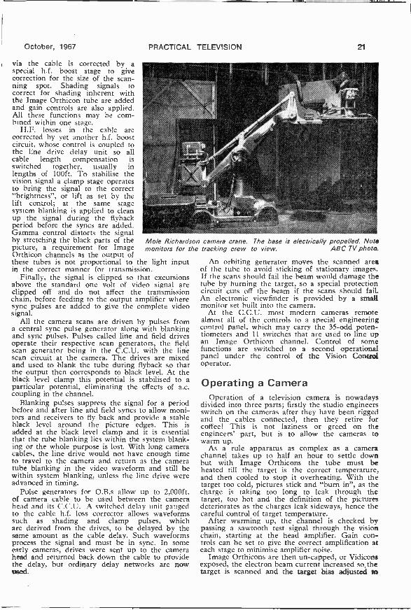
October, 1967
via the cable is corrected by aspecial h.f. boost stage to givecorrection for the size of the scan-ning spot. Shading signals tocorrect for shading inherent withthe Image Orthicon tube are addedand gain controls are also applied.All these functions may be com-bined within one stage.
H.F. losses in the cable arecorrected by yet another h.f. boostcircuit, whose control is coupled tothe line drive delay unit so allcable length compensation isswitched together, usually inlengths of 100ft. To stabilise thevision signal a clamp stage operatesto bring the signal to the correct"brightness", or lift as set by thelift control; at the same stagesystem blanking is applied to cleanup the signal during the flybackperiod before the syncs are added.Gamma control distorts the signalby stretching the black parts of thepicture, a requirement for ImageOrthicon channels as the output ofthese tubes is not proportional to the light inputin the correct manner for transmission.
Finally, the signal is clipped so that excursionsabove the standard one volt of video signal areclipped off and do not affect the transmissionchain, before feeding to the output amplifier wheresync pulses are added to give the complete videosignal.
All the camera scans are driven by pulses froma central sync pulse generator along with blankingand sync pulses. Pulses called line and field drivesoperate their respective scan generators, the fieldscan generator being in the C.C.U. with the linescan circuit at the camera. The drives are mixedand used to blank the tube during flyback so thatthe output then corresponds to black level. At theblack level clamp this potential is stabilised to aparticular potential, eliminating the effects of a.c.coupling in the channel.
Blanking pulses suppress the signal for a periodbefore and after line and field syncs to allow moni-tors and receivers to fly back and provide a stableblack level around the picture edges. This isadded at the black level clamp and it is essentialthat the tube blanking lies within the system blank-ing or the whole purpose is lost. With long cameracables, the line drive would not have enough timeto travel to the camera and return as the cameratube blanking in the video waveform and still bewithin system blanking, unless the line drive wereadvanced in timing.
Pulse generators for O.B.s allow up to 2,000ft.of camera cable to be used between the camerahead and its C.C.U. A switched delay unit gaugedto the cable h.f. loss corrector allows waveformssuch as shading and clamp pulses, whichare derived from the drives, to be delayed by thesame amount as the cable delay. Such waveformsprocess the signal and must be in sync. In someearly cameras, drives were sent up to the camerahead and returned back down the cable to providethe delay, but ordinary delay networks are nowused.
PRACTICAL TELEVISION 21
Mole Richardson camera crane. The base is electrically propelled. Notemonitors for the tracking crew to view. ABC TV photo.
An orbiting generator moves the scanned areaof the tube to avoid sticking of stationary images.If the scans should fail the beam would damage thetube by burning the target, so a special protectioncircuit cuts off the beam if the scans should fail.An electronic viewfinder is provided by a smallmonitor set built into the camera.
At the C.C.U. most modern cameras remotealmost all of the controls to a special engineeringcontrol panel, which may carry the 35 -odd poten-tiometers and 11 switches that are used to line upan Image Orthicon channel. Control of somefunctions are switched to a second operationalpanel under the control of the Vision Controloperator.
Operating a CameraOperation of a television camera is nowadays
divided into three parts; firstly the studio engineersswitch on the cameras after they have been riggedand the cables connected, then they retire forcoffee! This is not laziness or greed on theengineers' part, but is to allow the cameras towarm up.
As a rule apparatus as complex as a camerachannel takes up to half an hour to settle downbut with Image Orthicons the tube must beheated till the target is the correct temperature,and then cooled to stop it overheating. With thetarget too cold, pictures stick and "burn in", as thecharge is taking too long to leak through thetarget, too hot and the definition of the picturesdeteriorates as the charges leak sideways, hence thecareful control of target temperature.
After warming up, the channel is checked bypassing a sawtooth test signal through the visionchain, starting at the head amplifier. Gain con-trols can be set to give the correct amplification ateach stage to minimise amplifier noise.
Image Orthicons are then un-capped, or Vidiconsexposed, the electron beam current increased so, thetarget is scanned and the target bias adjusted to

22 PRACTICAL TELEVISION
The creeper, a very low camera mounting for low -angleshots. Rediffusion photo.
give a picture. Test cards or special slides are usedso that various focus controls can be set up. Ad-justment of the scanned area to fit a mask on thefaceplate of the tube gives an exact and consistentmethod of setting the aspect ratio and the scandimensions. Several other adjustments are made toan Image Orthicon channel but many controls areinterdependent requiring considerable skill andexperience to obtain the optimum results.
Many of the defects discussed earlier can beminimised by careful adjustments and compro-mises. Thus if beam focus is adjusted for absolutemaximum definition, the beam scans the electrongun assembly and this appears in focus. Just aslight defocus of beam hardly reduces definitionbut puts the surface and its marking almost com-pletely out of focus so that it is no longer objec-tionable. Many such adjustments are necessary andit requires great skill to line an Image Orthicon togive its best pictures.
Setting upWhen complete, the camera is exposed to a
standard test slide or caption. Adjustment of ex-posure is very critical as the Image Orthicon hasa non-linear input/output characteristic. ImageOrthicons tend to crush the white parts of thepicture and less signal is received from the high-lights than would be expected. Far from being adisadvantage, this non -linearity is welcome, as itpartly compensates for the display tube characteris-tics and helps to limit the effect of very brightobjects, reflections and flares from jewellery.
Sometimes black stretching is applied to give asimilar characteristic in the black parts of the pic-ture. Exactly when this white crushing occurs isvery critical when it comes to adjusting thecameras. In fact, it is such that a certain amountof crushing occurs and all cameras in the studioshould be adjusted to give a similar characteristic.This is not always possible with a device as com-plex as the Image Orthicon.
Vidicon cameras are much simpler to set up, asare Plumbicon cameras, and a complete line-uptakes only a few minutes.
After the engineering line-up, control is switchedto the simplified control panel carrying only thosecontrols needed for operational adjustments.
October, 1967
Rehearsals can then start. At the camera end of thecable, the cameraman has a list of the shots he isrequired to offer. "Framing", or adjustment of theposition of items within the picture, is achieved bymovement of a "panning handle" to point thecamera from side to side (panning) or up anddown (tilting).
LensesA turret of four lenses, each of different foal
length, can be rotated to bring each lens in frontof the tube to give the effect of different distancesfrom the subject. Rotation of the turret is achievedby a handle on the side or the back of the camera.Usually a special non-linear gearing is used tomove the lens quickly and quietly to the nextposition and align it in the correct position infront of the tube. Close-ups are provided by along focal length lens, wide shots by short focallength lenses.
Zoom lenses are now in common use, the mostpopular types being power operated over a rangeof 10:1. Controls for these operate on a rate ofzoom principle, using a twist grip to control thespeed of zoom. Speed control allows a muchsmoother mode of control which allows the camera-man to zoom slowly in without a trace of jerkinessyet, by turning the twist grip further, the lens canhe zoomed out at full speed. As well as this control,the cameraman can select four pre-set positions onthe range of zoom, allowing him to set up a givenshot with a given width of view very quickly.
Movement of the tube and its scan coils on acarriage is used to effect the focusing of fixed lengthlenses and usually requires adjustment when thelens is changed. Focusing of a zoom lens is con-trolled by movement of a lens element within thezoom lens itself, the tube focus mechanism beingleft as set up.
When the camera is moved on its mounting intowards the subject, or tracking in as it is called,adjustment of focus is also required, as in anychange of camera -to -subject distance. The focushandle is mounted on the side of the camera. Azoom differs from the track as the perspective altersto give a flat, foreshortened scene when zoomedin tight.
Outside broadcasts often show horses or racingcars apparently moving at a snail's pace towardsthe camera, completely spoiling any impression ofspeed. Test matches with grossly foreshortenedpictures are also often seen. Such effects are aresult of using telephoto lenses where it is im-possible to move the cameras in close enough tothe subjects, and a zoom lens zoomed in sufferssimilarly.
Camera MountingsMost camera mountings used in the studio have
wheels or castors to enable the'camera to be movedfrom set to set, also allowing the camera to bemoved in towards the subject. The simplest cameramounting is the tripod often seen with the legsfitted into a framework base which is carried bycastors. Various developments of the tripod ideaincorporating an adjustment for height and steering

October, 1987
all wheels together with a tinessystem have been developed.
Probably the most flexiblemounting in use today is the gaspedestal. Featuring steering of allwheels by a ring and a tiller, orone wheel by tiller alone, andsmooth adjustment of height withthe weight of the camera counter-balanced by compressed nitrogen,it can be accurately tracked orelevated by the camera alone, yet,with its small base area, it canmove into the most confinedspaces to give shots from the mostunlikely places without delay. Ringsteering of the tiller and counter-balancing allows the cameraman tomanoeuvre the camera to any posi-tion and elevate the camera withone hand, whilst the other pansthe camera.
Two men are required to operatethe simpler camera cranes.Operated hydraulically, thesetypically consist of a base whichcan be driven and steered in thenormal manner or can be crabbed (moved side-ways). From the base extends a jib which carriesthe camera and cameraman, allowing elevation orlowering as desired. Camera and cameraman arecarried on a platform with the pan and tilt headfixed to a vertical post at the centre of the plat-form.
Panning through 360deg. is facilitated by allow-ing the cameraman's seat to rotate on the same axisas the camera. Such a mounting allows more com-plicated tracking and elevations than the pedestal,but at the expense of size and manoeuvrability.Another crane in common use is the Mole Cranefeaturing a jib which can be swung from side toside as well as up and down, and is operated bythree people.
Occasionally huge cranes are hired for spec-tacular aerial shots and may require six or even
A huge camera crane specially hired for the occasion.ABC TV photo.
PRACTICAL TELEVISION 23
Camera line up; the engineering control panel. Rediffusion photo.
eight people to track the crane and swing the jib,which may be 40ft. long. On the other hand, lowangle shots can be obtained from a special mount-ing called a creeper.
ProductionClipped to his camera, each cameraman has a
shot card prepared by the production team indi-cating each shot by a number and a description -As the required shot approaches, the cameramanpresents the shot as required by the director atrehearsals. He hears the director's instructions(called talkback) in his earphones and can talk tothe vision controller who may relay his commentsto the production team
If the camera is mounted on a crane thecameraman can whisper instructions via an inter-com or give special hand signals to guide the cranecrew. Naturally, close teamwork is required forsmooth results so small monitors may be strappedto the crane to enable the crew to adjust theircamera's position as the performers move.
At the far end of the camera cable the thirdfunction concerning camera operation takes place.Sitting at a desk containing all the operationalcontrok, facing a bank of preview monitors dis-playing all the camera outputs, is the vision con-troller. His function is to match the pictures fromeach camera on the same scene so that facial tones,for example, do not change when a different shotis taken.
Matching of cameras requires very carefulmatching of the tube and gamma control character-istics during the engineering line-up. ImageOrthicons being extremely complex tubes havingvarying characteristics, it requires great skill to setup six different Image Orthicon cameras so thatthey all match each other.
In this country there are three main =mew-
-eantineied on pegs 28

The author describes the
construction and installation
of a combined aerial for BBC -1
and ITV, that may be fitted in
the loft, or mounted adjacent
to the TV receiver.
MANY readers of PRACTICAL TELEVISION willhave constructed their own TV aerials,possibly to designs that have appeared in
past issues of this magazine. The author has, aftermuch experimentation, come up with the designpublished herewith. Although the "simpler" typesof combined TV aerials are normally intended for"local area" reception, this aerial is in use in a"fringe area" and giving quite good results.
With careful attention to mechanical details andconstruction excellent results should be obtained.It is suitable either for set -top, or attic mountingusing 75 ohm low loss (semi air -spaced) coaxialcable. The photograph shows the prototype inwhich fixed (not telescopic) horizontal elementswere used. These consisted of 17in. lengths of lin.dia. aluminium tubing. These may be used if theconstructor so desires, but the type of telescopicaerial stocked by many radio component stockists(these are usually iin. diameter at the base) wereused in the final design. Three are required andeach should be capable of extending to at least19in.
The two semi -circular elements of +in. dia.aluminium rod should be fashioned exactly asshown in Fig. 1, bearing in mind the middle andlower section spacing. The ends are flattened.either by using a metal vice, or careful use of ahammer. Holes of Ain. diameter are then drilledwhere shown in the diagram.
The trio of telescopic aerials too, are flattened attheir ends, and -kin. holes are also drilled in these,and then bolted in their respective positions-oneOR each side of the upper paxolin strip and one tothe lower section. The whole is then bolted orscrewed to the base unit. This can either be ofpaxolin, or if this is not available, a suitable pieceof wood could be used. This should be approxi-mately 9in. long and have a 2 x 2in. cross section.
The underside of the base unit should be coveredwith a piece of felt or other suitable material if theintention is to stand the aerial on the set top.
INDOOR AERIAL
2"x 1" Paxolin strip
Telescopicaerial
extendedto 17"
9%; longcurved 1"; dia.section Aluminium
tube 231,2long
each side,Straight section I flattened
2" long J and drilled416 holesat ends
G. DA
Telescopicaerial
extendedto 17"
10:c
Straight section2" long
Telescopicaeri
extendedto 19"
,140
Paxolin orplastic block
Metalwork Coaxial 5"x 24x 1/alead toreceiver Paxolin
Suitable L type metal brackets, as shown in Fig. 1 basemay either be made up, or obtained from a localhardware shop.
If the constructor is unable to obtain theseitems locally, it is suggested that they may be madeas follows: obtain four 3M. lengths of hard brass Fig. 1: The drawing above gives all the major dimensionser other metal strip with a thickness of at least for the combined indoor aerial. Note the use of telescopic18.s.w.g. The width can be approximately bin.- horizontal sections.

FOR BANDS I &IIICLING
it should not be narrower. Each strip is thendrilled to take either 4 or 2BA bolts. When drilling,use the "first off" as a template for the otherthree strips to ensure that all the holes come inexactly the same place. One hole drilled towardseach end, should be sufficient.
Place the drilled strips in a metal vice and bendto form an L shaped foot. Stand the lower paxolinsection on the base unit, and mark or scribe thehole positions for the L brackets. Drill the paxolin
sections carefully, this is best carried out by layingthem on a wooden block or by clamping themtogether in the vice.
Coaxial cable is attached as shown and the farend fitted with a suitable coaxial plug, and theaerial is ready for use. It is not important to whichside of the aerial the inner conductor or braid isterminated. Good electrical and mechanical con-nections are very important. It is suggested thatsuitable solder tags are used under the heads ofthe bolts, and the coaxial cable soldered to these.This cable should preferably be of the semi air -spaced variety-especially if the aerial is to be loftmounted, and may be of any length (within reason).
Optimum resultsCorrect orientation of the aerial is necessary for
optimum results and this should provide nodifficulty.
If the aerial is to be positioned, on top of thereceiver, adjustment is quite simple. This alsoapplies to loft mounting (it can simply be stoodon the floor of the loft when finally adjusted, andleft-no fixing should be necessary).
Switch to the ITV channel and extend thehorizontal aerial elements to approximately 17inches. Rotate the aerial slowly for maximumpicture, adjusting the constrast control as necessary.Maximum contrast should coincide with maximumsound, but do not worry if there is some slightdeviation. The angle of the horizontal elements,set at 22°, was found by experiment, in theauthor's location, to be satisfactory for optimumreception on BBC -1.
Obviously other settings may be obtained whichmay give better results-but check sound andvision and adjust for a satisfactory balance.
Photograph showsthe author's orig-ina, prototype, thiswas before thetelescopic horizon-tal elements were
fitted

ServicingTELEVISIONReceivers
No. 139 - BUSH TV135/MURPHYV929 series
THIS series includes the Bush models TV135Rand RU. TV138R and RU, Murphy modelsV923, V923U, V929 and V929U. They are
dual standard with 19in. or 23in. tubes.Push button tuners are fitted. Bush models may
have type A506 or A514 (valve) or type A520,A527 or A528 (transistorised) u.h.f. tuners. 19in.Murphy models are fitted with A507 or A515(valve) or A522 (transistorised) u.h.f. tuners, while23in. Murphy models are fitted with A544 (valve)or A522 (transistorised) u.h.f. tuners. Because ofmounting differences the units cannot be inter-changed. V.H.F. tuner unit type A490 uses a PC900and a PCF806.
11
by L. Lawry -Johns
The v.h.f. tuner is normally set with two buttonsadjusted for any Band I channel and the other twofor any Band III channel. This arrangement can bechanged if desired to provide any combination ofchannels in Band I or III.
To revise the switching, remove the tuner unitfrom the cabinet (see later dismantling instructions)remove the cover by pressing in the end, liftingslightly and disengaging the other end. Slackenthe P.K. screw securing the switch actuating tabto the rocker bar. Reposition the tab downwardif Band III is required or upward if the buttonis to tune over Band L
a ,/*/=
1 1C14 1R131000pF iookn
Fig. 1: Circuit diagram of the v.h.f. tuner unit.

October, 1967
To 1st anode(pin 3) of
CRT.
PL12
37351M.O.
Toanode PL12(pin 4)
of CRT.3R34
PL11
1M11
1M3R
Skt10Focus
3R321 MO.
3R37
1M11
3VR4D3
70V10
mA
Boost3R3680kft
3RV62M.O.Height
PRACTICAL TELEVISION
3RV81M.O.
Gen. un.
470kfl 3C313R434.7kfl
3RV1250k.O.
Interlace2
,3V6a72
FieldPCL85
oscillator
3RV5. 1MI1
Field hold.
0.01}.F
3R38220kfl
3140.1uF
3R4133kfl
3R4215kfl
4/A: 3C 3011.2.(47}IF
Fig. 2: Circuit of the self -oscillating field timebase used in this series of models.
3RV7150kfl
Top hn.
3R67221(.0.
3R451M.O.
3T3
27
Field deflection coilsHT4
P/S 5-3
3C370.047pF
PCL85 T3V6b
mlm /27 70.tput To 3723,
3R30,3C53, inpututon line timebase
3C35 3R47500 270
,uF n
8
3C290pFM1S
3MR339
Oscillator adjustmentTo adjust the tuning of a particular button, press
it in to select the desired channel, then pull it outto engage the spline on the tuning spindle. Rotatefor optimum reception and then press in to dis-engage the spindle.
When the button will not engage the spindle, i.e.,the tuning is unaffected when the above procedureis followed, examine the button itself (removetuner) as the engaging slots may have been wornaway.
Fractured oscillator coreQuite often it may be found that the buttons
are partially or wholly inoperative, sometimestuning when set on one channel but being hope-lessly out of line when next operated.
This is nearly always due to the plastic corebeing broken inside the coil former. This corecarries a number of brass sleeves which tune thecoils as it moves inside the former.
Various dodges may occur to the repairer tokeep the core operative whilst a replacement isbeing obtained, e.g., spring loading the rear (open)end to keep the core pressed at the fracture.
Replacing the core may appear rather difficultbut in fact it is quite easy if it is remembered thatthe tuner is in two main parts which may beseparated by taking out the P.K. screws at eachside. This exposes the end of the core.
V.H.F. tuner removalRemove the power and i.f. plugs from their
37b14n25
at°C
3R6239kfl
3R6468k.O.
376315kfl
:3C49000pF
sockets on the receiver unit and release the largehexagon bolt securing the tuner unit bracket sup-port to the cabinet.
Withdraw backward to disengage front locatinglugs. At this point the buttons will probably fall off.
U.H.F. tuner removalSimilar to above but two bolts are used at the
rear which should only be slackened, not removed.
Trouble spotIntermittent reception with or without a snow-
storm is most often due to incorrect operation ofthe standards switch. Cleaning (and very slightadjustment if really necessary) will generally over-come this trouble. Also check the plugs andsockets on the receiver p-nel.
Special featuresThese receivers do not use a mains dropper, the
large tapped resistor at the rear is the voltageselector and consists of two 47f1 sections only.The voltage at these sections is d.c., obtained froma BY101 silicon diode (3SR2) which of courseonly conducts on half cycles, thus effectivelylowering the voltage available to the heater linesince there is no reservoir capacitor (to fill in thetroughs).
This is a very neat way of obtaining the requiredheater current, but there are two points whichrequire comment. A voltmeter will not read thetrue voltage. For example, at a convenient pointsay the tube heater pins where the correct voltage
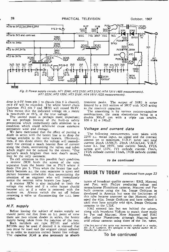
28 PRACTICAL TELEVISION
HT1b to 2V1,2,3,4,2R44,2RV1
HI1a to 3V3 and contrast
012 to 3V1, 3V7a
H.
P/S 3-6+
4100
pFyF
P/S
2 \4/1711113/S
9-2
4 40-1 r-0
P/S P/S11 1E!_S4
3-3 2-2 L
tuner tuner loccoFVHF. UHF
PL17 PL18 PL19
2210V200V 3 220V 250V0V
240V
Skt12
Skt11
PL16
October, 1967
11^-3C01480.
3SR1 3SR
2V4 p 3V33-2
2C511.000pF
3F11A
3R66B 54 7 11v1.0.
.47k113R741
o
Fig. 3: Power supply circuits. HT1 234V; HT2 216V; HT3 212V; HT4 191V (405 measurements).HT1 223V; HT2 199V; HT3 210V; HT4 181V (625 measurements).
drop is 6.3V from pin 1 to chassis (pin 8 is chassis),only 4V will be recorded. The whole heater chain(junction 3V2 pin 7 and 3R58) will record 98-8V.This means that the indicated voltage on a meteris two-thirds or 66% of the true voltage.
The second point is perhaps more important;we say perhaps because of the built-in safetyprecaution which immediately calls attention to acondition which could otherwise cause extensivepremature wear and damage.
We have mentioned that the effect of putting adiode in series with the heater line is to drop thevoltage available to the valve heaters. Obviously,then, if this diode shorts the voltage will immedi-ately rise causing a much heavier flow of currentalong the chain, overrunning the valves and tubeswhich might not be noticed by the viewer. "Ourpicture's much brighter than next door's mum,"may be the only comment.
To call attention to this possible fault conditiona resistor 2R38 feeds the screen of the syncseparator from the heater line at PS/3 where itfeeds 2V4 pin 5. Thus when the heater line sud-denly becomes a.c. the sync separator is upset andpicture becomes unlockable thus necessitating theattention of an engineer who will immediatelynotice the overrun valve heaters (we hope).
A resistor 3R74 is also included to limit thevoltage rise when and if a valve heater shouldbecome o/c or if a valve is removed with thereceiver on. Always switch the set off beforeremoving a valve or disconnecting the c.r.t. basesocket
H.T. supplyBefore leaving the subject of mains supply we
should point out that from an h.t. point of viewthere are two silicon diodes in series, the heatersupply being taken from the junction of the two.
Both rectifiers are type BY101 and whilstBY100s may be used if desired it is stressed thattwo must be used and the original circuit adheredto in order to maintain correct heater line voltage.The capacitor 3C48 is also necessary to absorb
3S1
AC.mairrs
transient peaks. The output of 3SR1 is surgelimited by a 16f2 section of 3R57 with 3C43 actingas the reservoir capacitor.
The smoothing is by various resistor -capacitorcombinations, the main electrolytics being in adouble 300ILF can with a triple can nearby,100 + 32 + 100p.F.
Voltage and current dataThe following measurements were taken with
225V a.c. mains input, no signal and the contrastcontrol set to minimum. U.H.F. tuner unit totalcurrent 26mA (A506,7), 23mA (A514,5,44). V.H.F.tuner h.t. line 195V, total current 34mA, 1V2Ascreen grid 132V, 1V1 cathode current 15mA,1V2A cathode current 11mA, 1V2B cathode current8mA.
to be continued
INSIDE TV TODAY continued from page 23
turers of broadcast quality cameras: EMI, Marconiand Pye; with Philips producing colour andmonochrome Plumbicon cameras. Marconi and Pyebuilt cameras using the 3in. Image Orthicon asdeveloped in America but soon the limitations ofthis tube became apparent so that Marconi devel-oped the 4f in. Image Orthicon and have refined ituntil they have actually sold 41in. Image Orthiconcameras to the USA.
EMI entered late but not behind the others,along with broadcast Vidicon to match those madeby Pye and Marconi. Now Marconi and EMIoffer colour Plumbicons although Marconi havesold colour cameras using three of the 3in. tubes.(The first part of this series was incorrectly credited to a reader,Mr. A. F. Cameron. We apologise to the rightful author M. D.Benedict for this error ,)
To be continued

GOVERNMENT WhitePapers are rarely whiter -than -white, especially when
they have anything to do withradio, TV, newspapers, filmsand the theatre. They are oftenlike the heavy clouds which por-tend parliamentary legislation,leading to more restriction, moreinspection, more taxation andmore jobs for the boys. Thewhite papers are usually meta-phorically and politically tinted,not necessarily influenced by thegovernment in power. Thevoluble dislike of commercialtelevision by some members ofthe Pilkington Committee, forinstance, has had regrettableeffects on television as a whole,as we all know.
National film school
Now it is the turn of the filmindustry to be subjected to agovernment committee - theLloyd Committee-with the fol-lowing terms of reference:-
"To consider the need for aNational Film School and toadvise, if necessary, on the objectsand size of such a School, itspossible location and form oforganisation and the means bywhich it might be financed."
The Lloyd Committee wasappointed in October 1965 andhas just completed its report, awhite paper with a green cover,presented by the Department ofEducation and Science. It is afact that the film productionindustry, which deals with artis-tic product, is basically highlytechnical, and one would expectthe report to be down-to-earthand practical. Though the inten-sions were admirable, the Com-mittee contained no knownengineers or technicians and con-sequently tended to deal withartistic problems of a past agerather than plans for the future.Nevertheless, its report seemedto exude that "culture" of doubt-ful quality which is fashionabletoday.
Pay up ! Pay up ! Pay up!
The amount of negative filmphotographed for television isnow at least ten times as muchas that used making films forthe cinema, both on 35mm. or16mm. film. The number ofcinemas is declining. The tech -
HERNI
THE DIPOLEniques of television and cinemafilm making are getting closer andcloser together. The Lloyd Com-mittee have reported that thecapital outlay for land and build-ings for a film school in a sitein Central London will cost£600,000 and the initial equip-ment £200,000. Notwithstandingthe rapid progress made in someBritish film studios in the lastfour years, the Lloyd conceptappears to relate more to film-making of twenty years agothan to the latest techniques. TheLloyd Committee's attention tothe cultural importance of theRoyal College of Art, the SladeSchool, the London School ofFilm Technique and other educa-tional bodies fills one with appre-hension. The declining standardsof some of the dramatic schoolsis, indeed frightening, not onlyon account of the poor dictionof their students, but because ofsloppy production, down -beatoff-colour plays and other short-comings. They are not all beat-niks, however. The Bristol
drama group is the best I've seento date.
Down the kitchen sinkOn a back page of the Lloyd
Report several societies are credi-ted with offering advice, includ-ing the British KinematographSound and Television Society-an organisation which has longtaken interest in training by theprovision of special tutoriallectures fee -paying courses andarticles in its journals. "Credits"are important. On inquiry of theBKSTS as to the contribution bythat society to the Lloyd Report,I was told that its sole participa-tion was a letter fromthe Society's Chairman to theLloyd Committee's Secretarystating that if a film school was tobe built, it should be in London;that it should be of benefit totechnicians in film and alliedindustries and that suitable tech-nical training would be accessibleto candidates wanting to enterthe film industry.
That, believe it or not, wasthe sole communication fromBKSTS on the subject. If theLloyd Committee's recommenda-tion for a National Film Schoolis carried out along the lines -nowsuggested, without technicaladvice, one can anticipate teeth-ing troubles. Will there bethousands of pounds pouringdown the cultural kitchen sink,paid for by hard-pressed cinemaexhibitors or equally hard-pressedtaxpayers?
Arty -craftyAs for the so-called creative
side of a National film school,is this the type of trend -settingtalk we can expect? The follow-ing was actually printed in aprogramme of a students' per-formance :-
"It is cruelty that cementsmatter together, cruelty thatmoulds the features of the world.Good is always on the outer facebut the face within is evil, evilwhich will eventually be reduced,but at the supreme instant wheneverything that was form will beon the point of returning tochaos."
This was part of the descrip-tion in the programme of A spurtof Blood, a playlet produced bythe students of the Royal Collegeof Art recently. On the sameevening they presented The GasHeart, described as : -
"Aortaorb cotnetobe nipplebog

30 PRACTICAL TELEVISION
pebbletongue bladdercloud crag -plasma bonevapour sandvalvebowelcanyon ethernerve . . ."
The "credits" of this master-piece included a "designer of setsand pneumatics", in addition toa projectionist and a choreo-grapher
If this is the type of "culture"they propose for the NationalFilm School, then the soonerengineers take charge, the better.
Colour ProcessingProcessing of black -and -white
film plays an important part inall television areas, at both BBCand ITV studios, large and small.News and magazine items inblack and white are speedily pro-cessed and then cut and edited innegative form. On telecine, thenegative film is turned into apositive picture by phase reversal.
The editing machines in TVstudios usually of the continuousmotion type, such as those madein Britain by Rigby, Acnnade andEditola or the continental onesfrom Steenbeck and Prevost. TheMoviola, Acmiola and other typeswith intermittent sprockets areeasier to thread up. These aremore popular in film studios,where positive prints are used forediting and a few scratches don'tseem to matter.
Now we come to colour pro-cessing, at present carried out inlarge commercial film laboratories,such as Technicolor, Denham,Humphries and Kays, whodevelop and print 35mm. and16mm. and even 8mm. The "roadshow" 70mm. prints are alsomade at Technicolor. Televisionstudios will use 16mm. film forcolour news, utilising colourreversal stock for their "local"programmes plus 35mm. for bigfeatures.
The BBC have just takendelivery at Alexandra Palace ofthe new colour processingmachine (for the Kodak ME 4system), supplied by Photomex(London) Ltd., who already havea large number of orders in hand.Processing colour, especiallyreversal, is of course much morecomplicated than b. and w..requiring about 12 baths andother treatment. Newman andGuardia, of Harlow, Essex. makersof many types of automatic pro-cessing equipment, are also aboutto complete tests on a 16mm.colour film processing machine
suitable for London and regionaltelevision stations. It is interest-ing to note that British -madeblack -and -white film processingplant is used in large numbersof television studio centres allover the world and it rather looksas though the success of thesetwo British made equipments willbe similarly repeated on colourtelevision.
Colour burst
Transmitter link equipment,camera equipment, control equip-ment, telecine equipment-allcolour (or almost all colour) isthe policy and the order placedwith Marconi's Wireless Tele-graph Company by the YorkshireTelevision Network. Sixteen ofthe new model VII Marconicolour cameras will be deliveredto the YTN studio centre inKirkstall Road, Leeds, which willcontain a large (4 camera) studio,a medium (2 camera) studio anda presentation (one camera)studio, plus two outside broad-cast (4 cameras each) trucks.There will also be three Marconicolour telecine equipments for35mm. and 16mm. films plusslides. The cost of all this up -to -dater -than -to -date equipmentwill be £650,000 and is thelargest single order of TV studioequipment ever placed in thiscountry.
Society's problem
At a time in history when manseems intent on harming hisneighbour and himself; whentelevision is rooted in society asthe medium for purveying newsand views-news of what, andthe views of who?
The juxtaposition of horrificnews items and syrupy soapoperas-this is when the trulymoving programme can reallysear into. the viewers mind. Suchprogramme was So many Child-ren written and produced byJohn Pett, a bulwark of West-ward Television but almost un-known nationally. His programmedwelt on the problem of mentallyhandicapped children, and inarticular with those 62 pupilsat the Downham Junior TrainingCentre at Plymstock, near Ply-mouth. For too long there has
October, 1967
been a veil drawn over thedevoted and patient work, andof the great advances made inthe care of the retarded - andof teaching the parents to cope.The greatest tragedy is that thereare not enough Downhams andschools like Downham to do thejob.
With their "Emmy Award"for Wyvern at War safe at theirPlymouth headquarters Westwardseem to have a formula for docu-mentary TV-linking video tapewith filmed sequences; what apity that the regional stationshave insufficient budgets forshooting in colour for world widesale to the countries where colourTV is real TV! Director DavidScott, and the camera team ofGerry Ewens, David Howarthand Trevor Mathews turned ina first-class job. But we mustalso thank the ITCA for network-ing such a programme at a peaktime.
A play within a play, or a filmwithin a film have always hadan appeal to me, and when theplaywright is a film director andthe TV play is about a "cinemaverite" documentary about a film ,
director known to everyoneas "R. G."-then I watchfor technical knowhow. WolfRilla wrote the play for theLove Story series, and JohnGregson reproduced a typicalfictional film director - com-plete with his own projector,studio lamps, and canvas chairwith his name on it "R. G.Bishop". But these were card-board characters which the actorstried hard to animate-I keptthinking of that Peter Cook andDudley Moore "send up" of theepic that never was in one oftheir series. I bet John Gregsonwas glad he didn't have to shavehis head and wear a monocle!
Johnny Morris can put hispersonality on any programme,whether it's Hammy going up theriverbank, or viewing the NiagaraFalls in a monk -like mackintoshhabit from under the falls. Hiscomment that his original inten-tion was to stay an hour at thefalls, and instead staved two dayswas true to life, rather than the"from our own correspondent"style when the commentator isflying from one airfield toanother.

LETTERSTO THE.EDITOR
625 LINES IN 405 CHANNELS
sIR,-Mr. Hopkins' novel ideas about theanatomy and physiology of the eye are not borne
out by the facts (PRACTICAL TELEVISION, Mayand June). To suggest that the perception of flickerhas anything to do with the push-pull action ofthe iris muscles is inaccurate and an insult to therefined data processing that goes on in the retinaand visual areas of the brain. For anyone interestedin this fascinating area of biological computationI will be happy to recommend some simpleaccounts of the latest thoughts on the matter.
His proposals for improved television scanningstandards are interesting, and should be noted byanyone designing a television system from scratch.It is easy, though, to "be wise after the event",and the prospects'of changing even this country'sstandard is remote. Apart from the initial muddlesuch a change would cause, the cost would surelyprevent its being carried out. The gas industry isfinding how difficult it is to change from onestandard (Town gas) to another (North Sea gas)even with small areas of the country. A nationaltelevision change would therefore seem impossible.-J. MELLERIO, PH.D. (Department of PhysiologicalOptics, Institute of Ophthalmology).
The Author replies:Several enquiries or comments have been made,
some by correspondence and some in thesecolumns, regarding the optical and physiologicalinformation contained in the above article. Readersunfamiliar with the relation between visual opticsand television may welcome some clarification ofsimilar questions which may have arisen.
The diagram of the eye in Part 1, is greatlysimplified, as I stated, for easy explanation of itsreception of a television picture. The two irismuscles actually have a complex structure, butthey "push" the pupil smaller (by dilation) as Iexplained. Flicker does not activate the iris; a lightflash activates the retina, which then signals (viathe optic nerve) for protection by a reduced pupil.Slow pulsations of light and dark make the iris tryto admit a comfortable light level, but its slow"push-pull" is unpleasant; at about 50 flashes (fieldsweeps) the pupil settles to a stationary aperturewhich satisfies the visual demand.
The retina, receiving a steadily repeated image ofthe traced picture, retains each image for about1115 second before fading commences. The cinemawould still project only 16 film pictures to thescreen each second if the original sound -track hadbeen compact enough to insert in the relative frameof the "silent" film. There was no flicker in /928;it was eliminated by flashing each stationary framethree times to the screen.
If you check scanning spot size, as suggested,by closing up the lines, and find less than one-third of your screen is left unscanned, you must
SPECIAL NOTE: Will readers please note that weare unable to supply Service Sheets or Circuits ofex -Government apparatus, or of proprietary makesof commercial receivers. We regret that we are alsounable to publish letters from readers seeking a sourceof supply of such apparatus.
The Editor does not necessarily agree with the opinions expressedby his correspondents.
be getting a hazy picture; either the spot is outof focus or your e.h.t. is down.
"Triple -interlacing" has been condemned in thepast as showing "line crawl"; this and otherunwanted optical effects such as the familiar"patterning" and "moire" are seen because thetraced lines are seen individually. The lines arevisible because they are separated; close them upand unwanted effects cannot appear.
"Three -field scanning" implies that each tracedfield fills one-third of the screen, using the present"twin -interlace" spot which covers only two-thirdsof the screen by two field sweeps as we haveproved. How else, other than by three fields, cana really complete TV picture be formed, withdefinition balanced in both dimensions to achievethe highest pictorial quality?-A. 0. HOPKINS(Worthing, Sussex).
COLOUR TRANSMISSIONS
SIR,-Prior to the construction of some of thePal decoder circuits I have been attempting to
observe the 4.43Mc/s colour burst on the presentlocal colour transmissions. For this purpose I amusing a 625 converter unit and an oscilloscopewith 6Mc/s bandwidth. The i.f. bandwidth hasbeen flattened, using your recently describedwobbulator, to the required limits. I am surprisedto find that no visual evidence can be seen on theoscillograph of the burst signal, although the linesync pulse and back porch is extremely clear.Whilst appreciating that a clear 90° wide sine waveis unlikely, I rather expected a hazy outline. I havechecked the oscilloscope and it re.ohres 5Mc/seasily.
Have you any comments to mat' on this experi-ment?-JoHN F. CANNELL (I ,eford, Hants).
[Since the i.f. bandwido .s been increased tothe required extent, the r; ,tor (or video amplifier)output will contain 4.4 s components if anyexist in the signal. Since the line sync pulse is"extremely clear" it may be assumed that rise -and fall -times are not degraded in the oscilloscopeamplifier, whose bandwidth must therefore be ofthe order of I or 2McIs at a minimum. Hence,either
(a) some intermediate signal amplifier (betweenreceiver output and 'scope input) has band-width less than 4.4.7Mc 1 s, or
(b) the receiver output contains no componentat 4.43Mc/s.
Since neither of these appears to be the case, itappears that there is some fault in observation. Isuggest the following consideration.
(a) If a whole line is displayed-about 60µS-each cycle of a signal at 443McIs occupiesabout 11200 of the line as displayed; or, ona 3 -inch tube face, 0.015 inches. It could be

32 PRACTICAL
missed, if there is any appreciable fitter.Great care will be needed in synchronising,and I would hazard a guess that unless asignal/noise ratio of at least 26dB (voltage)exists, the colour -burst will not be seen.
(b) Try synchronising the displayed line witha 4.43McIs signal from a suitable signalgenerator -1 presume the 'scope in use hasprovision for external sync.
(e) In any case, it is possible that the syncpulses as transmitted are not accurate toabout 20 to 50 nanoseconds, nor is theinitiation of the colour -burst so accurate asthis. Should this be the case, apparent jittermay well be occurring and if greater thanabout 1110 of I% may readily obscure the443Mcl s display.
I regret the rather vague figures but I have noaccess to my text books at the moment-however,the above may help.]-D.R.B.
THE FIRST OF MANYkJIR,-I am fortunate in having every issue of
PRACTICAL TELEVISION except the very first-that is, April 1950. As you may remember, thatissue became out of print within a few hours ofpublication on March 24, 1950 (your editorial,May 1950). If any other readers would care tosell me a copy of this magazine, I should be verygrateful to him or her.
I would also like to mention that I would bepleased to lend any copies to any readers for aslong as they wish, providing that they return themin the condition in which they were lent.-A. G.FOSTER (44 Warwick Road, Luton, Bedfordshire).
PTV SUPERVISORSIR, -I would be grateful if any reader could lend
me the third blueprint for the P.T.V. Super-visor together with the relevant literature.-A.PEARSON (148 Portman Street, Middlesbrough,Yorkshire).
DX -TV-continued from page 14
Austria, Norway, USSR, Yugoslavia, Poland, andperhaps best of all Finland E3 (card Marked TVI).
Graham Deaves of Hitchin is another DXerwho has been complaining with some justificationabout the confusing mass of J.R.T. Yugoslav testcards and patterns. We agree there has been noimprovement here and have now seen J.R.T. usingthe E.B.U. card with Zagreb in white letters onit, so that is still another version! Graham hasbeen maintaining his reputation with W. Germany,Canary Is., Italy, and Hungary under the recentdifficult conditions.
Ian Rose of Blackburn is going to be dis-appointed. Our note of last month about his pos-sible Amman, Jordan E3 reception has producedother replies saying firstly Amman is not yet inservice, and secondly the Amman caption wasprobably part of a R.A.I. Italy newsreel on Ch.IA, in connection with the recent Middle Easttroubles.
TELEVISION October, 1967
COLOUR AND MONOCHROMEPATTERN GENERATOR
Labgear Ltd., Cromwell Road, Cambridge,announce their Pattern Generator type E5180which is specifically designed to provide facilitiesfor the installation and adjustment of colourreceivers. It gives the necessary patterns to enablecorrect convergence of red, green and blue beamson the colour tube. Being fully transistorised andbattery -operated, there is no trace of hum, and itis fully stabilised against battery voltage variation.An on/off indicator lamp is provided and a slowmotion drive for r.f. tuning.
Operation is on 405/625 lines, Channels 6-13and 26-52 (for A, B and C channel groups). Thepatterns generated are: dot pattern, used for staticconvergence of a colour receiver. Crosshatchpattern, used for dynamic convergence. Verticalbars, used for horizontal linearity adjustment andhorizontal lines, used for vertical linearity adjust-ment. Price is £75 net.
Integrated Test Oscillatorby A. J. McEvoy
PRACTICAL TELEVISIONAUGUST 1967
Messrs. Ferranti Ltd., Gem Hill Chadderton,Lancashire, have informed us that the ZSS54A isonly available on a 4-6 week delivery basis at acost of 102/- each. They are however, able tooffer a much cheaper alternative from stock.This is the ZSS134A which costs 62/6d. andfulfills the same requirements.

COLOUR Is con=A SHORT BASIC COURSE ON COLOUR TV FORTHE TECHNICIAN AND AMATEUR ENTHUSIAST
by Al PRIESTI.EY
PART 5 - DECODING PAL
THE term decoding refers to the process ofextracting the colour information from thecombined R-Y and B-Y chrominance signals
picked up by the receiver. In its strict sense it issimply another from of dectection, but it is con-venient to talk of a "PAL decoder", meaning thewhole group of circuits which accept the chromi-nance signals, process them, and provide R-Y,B-Y and G-Y colour -difference output signals atamplitudes of up to 200V peak -to -peak for drivingthe grids of the three guns in the colour c.r.t. It isa completely self-contained part of the receiver cir-cuitry and is often manufactured as an indepen-dent assembly-usually on a printed circuitboard. It is also the only part of a receiver which isgiven over wholly to colour.
INPUT AND OUTPUT WAVEFORMSBefore we start to consider colour signal pro-
cessing let us be quite clear what sort of signalappears at the input of the decoder, and what sortof drive voltages we shall expect from the colour -difference outputs. Fig. 17 shows a chrominancewaveform after it has been removed from thevision carrier. It corresponds to the standard BBCcolour bar test pattern and will commonly be atan amplitude of a fraction of a volt. Notice theburst signal transmitted during the back porchinterval of the waveform. This consists of about10c/s of unmodulated chroma subcarrier.
4111110.
r, cc 4'S'
>T2 o 0 cT3
T10 c/s of burstThe phase of the combined sub -carrier varies from colourto colour; but is at a constant frequency of 4.43361875 Mc's
+ its sidebands
It should at this point be mentioned thatsuppressed carrier transmission is used for thechroma signals. With this technique the subcarrieris suppressed at the modulator stage in the trans-mitter, only the sidebands, which contain theactual B-Y and R-Y information, being passedon to the output stages of the transmitter for trans-mission via the aerial system. To simplify matters,however, we shall in this section in referring to thechroma signals refer to the chroma subcarrier as ifit were transmitted along with the chroma side -bands.
In our discussion of the transmitted signal wesaw that the phase of the subcarrier at any instantin time is a measure of the hue, while the ampli-tude of the subcarrier tells us the saturation-i.e.how much of a particular hue or colour is beingtransmitted. So during any particular colour barin the BBC colour bar test pattern the phase andamplitude of the subcarrier is constant, but as soonas the next bar comes along the phase changesbecause the hue changes.
010
0
0
>-
a
0
a
2 acc
O B -Y
O G --`t
O R -Y
Fig. 17: Chrominance subcarrier representing the Fig. 18: Colour difference output signals for the standardstandard co/out bat test pattern. colour bar test pattern.

34 PRACTICAL TELEVISION October, 1967
r+.1
-1-11
4.4 MO Gating offpulse
Input Chromaamp.A
Chromaamp. B
Burstamp.
D.0
Colourkiller
!dentfilteramp.
1,1Imml Atten.
Direct path-{ Adding
Delayline
Delayed pathL
Matrix
-Line trigger pulse L
41.
Burstonly
L1 Phasesensitivedemod.
_11 ,Gating on Ipulse
circuit
D.C.
-1_Subtracting
Referencecarrier
90°phaseshift
Fig. 19: Block diagram of a typical PAL decoder.
R-Y, B-Y and G-Y colour difference outputsfrom the decoder for the various bars in the BBCcolour bar test pattern are shown in Fig. 18.
BASIC PAL DECODERA typical PAL decoder contains quite a large
number of separate circuit functions but these canconveniently be split up into two groups. Onegroup of circuits carries the actual chrominancesignals, whilst the other comprises a number ofauxiliary functions most of which are concernedwith providing a reference carrier of correct phaseto enable the chrominance information to be extrac-ted by the aroma demodulators. Fig. 19 is a blockdiagram showing the operations carried out on thesignal between the input and output of thedecoder. Let us follow the path of the signal anddiscuss the functions of each group of circuits inturn. Afterwards we will consider the auxiliarycircuits and see what part they play in the completedecoder.
CHROMINANCE AMPLIFIERSThe first block on our diagram is a tuned
amplifier. More commonly this will consist of twobandpass stages (A and B) each tuned to a centrefrequency of 4.4Mc/s and with a bandwidth ofabout ±1.0Mc/s. The amplitude response isshown inserted in Fig. 19. The bandwidth is wideenough to include all the worthwhile sidebandinformation carrying the colour detail.
In some decoders the first stage is gain controlledand so a d.c. bias will be fed in from the
1 Signalcircuits
lAuxiliaryfunctions
Clampcontrolpulses
8 --Y
G-Y
R-Y
chrominance a.g.c. circuits, now commonly knownas a.c.c. (automatic chrominance control) circuits.We will consider this in more detail later.
The second stage is gated by means of a pulsederived from the line flyback pulse. This cuts thestage off during the flyback period so that theburst signal is not passed on to following stages.The burst signal, if not removed at this point,could otherwise interfere with the colour reproduc-tion.
DELAY LINE
There are several different techniques ofchrominance signal processing but the commonestone, which we are considering here, uses a delayline. The purpose of the line is to delay, or storeup, the signal for a period of time equal to onescanning line. As a result of this we have at theinput to the matrix at any given instant the pictureinformation being received together with the cor-responding information for the same point alongthe preceeding line, i.e the point immediatelyabove it in the picture. This enables an averagingprocess to be carried out in the matrix (or mixer)which causes certain hue errors to be cancelled.
A typical delay line is illustrated in Fig. 20.This is of the folded type such as is currentlymanufactured by Mullards. It consists of a blockof glass fitted with two electroacoustic transducers.If an electrical impulse is fed to one of thetransducers it is converted into an acoustic impulse(or sound wave) which then travels through theglass, bounces back off the end of the line, ispicked up by the second transducer, and convertedback again into an electrical impulse. The output

October, 19671967
Input signal Sound wave
'Transducers
Delayed signal
PRACTICAL TELEVISION
Glass block
This end is ground down so thatthe block gives precise delay time -
required, approx.63.91.1S
Fig. 20: A folded glass delay fine.
impulse is delayed by the time taken for the soundwave to travel down the block of glass and backagain. The time interval is therefore determinedby the characteristics of the glass and by thelength of the block, and each line can be groundvery accurately to a predetermined delay time.The type of glass used has to be carefully chosento have a low coefficient of thermal expansion sothat the delay does not vary significantly withchange of temperature. The delay time is approxi-mately 63.9uS -(one line of a 625 -line picture).
MATRIXING
Matrixing means mixing-adding or subtracting.It usually consists of a resistive network and hastwo separate inputs. One input comes from thedelay line and consists of the chrominance sub-carrier signal which has been stored up for oneline. The other input comes straight from thechrominance amplifier via an attenuator to com-pensate for the loss in the delay line. We thereforehave the chrominance information from the currentline together with the corresponding informationfrom the previous line: both at exactly the sameamplitude. These signals can be processed togetherbecause in practice the information is remarkablysimilar from line to line.
In the matrix we add these two signals as oneoperation, and we subtract them as another. Thisgives us two new subcarriers of constant phase inplace of the single combined subcarrier of variablephase. One has an amplitude proportional to theR-Y signal, and the other proportional to B-Y.Note once again that we are no longer interestedin the precise phase of either carrier. Now let ussee how this comes about-it is much more simplethan it sounds.
Figure 21(a) shows the combined chrominancesubcarrier and how it is derived from the originalindividual R-Y and B-Y modulated carriers fortwo successive lines of the picture, both havingthe same hue. (See "Transmitting Colour",PRACTICAL TELEVISION, August 1967.) This is theinformation that is arriving at the matrix. Fig. 21(b)shows what happens when we add these signals.The result is a carrier of the same phase as theoriginal B-Y carrier, but twice its amplitude.Similarly if we subtract them we get a resultantcarrier equal to 2(R-Y).
So we now have two separate subcarrier out-puts from the matrix: one R-Y and one B-Y. Allwe have to do is to measure their amplitude andpolarity. Note that the colour -difference signals can
35
Combined carrier
Fig. 21(a): Combined chrominance subcarrier foralternate lines of the picture (same lute).
2 ( R-11
2(B-Y)
Combinedsubcarrierfor successivelines of a picture(see Fig.21a)
Fig. 21(b): The matrix adds the subcarriers from twosuccessive lines to give 2 (B-Y) and subtracts them to
give 2 (R-Y).
be either positive or negative, and here is therub. Because we need to know their polarity aswell as their amplitude we cannot use ordinaryamplitude detection with a single diode: we haveto use synchronous detection instead.
MATRIX VECTOR DIAGRAMSSome people think best in terms of vector
diagrams, so before going on to consider synchron-ous detection let us re -draw the matrixing processin another .way. Instead of drawing several cyclesof several sinewaves we draw arrows representingthe height of each sinewave. We can then plot thearrows on a circle of 360° (one cycle) in positionswhich represent the phase angles between thesignals. We know that the R-Y signal leads theB-Y signal by 90° (because of the quadrature

36 PRACTICAL TELEVISION October, 1967
2 (R -Y`
B Y B -Y
(a)
B-Y cancels
SUBTRACTING
(c)
R -Y cancels
ADDING
(d)
2 (13-Y)
Fig. 22: Vector diagrams of the matrixing operation,which gives outputs of 2 (B-Y) and 2 (R-Y).
modulation technique used), and so this leads toFig. 22. In (a) we show the signal transmitted on,say, line 1. In (b) we show the signal of line 2.Fig. 22 (c) and (d) shows how outputs of 2(R-Y)and 2(B-Y) are obtained when the signals areadded and subtracted in the matrix.
If the combined subcarrier is delayed due todefects in propagation or through any other cause,a phase change is introduced which in the NTSCsystem causes hue errors. In delay line PAL how-ever the phase error is cancelled and does notcause any change in hue but results in desaturationinstead, because the resultant R-Y and B-Ysignals from the matrix are slightly too small: thisis illustrated in Fig. 23.
SYNCHRONOUS DETECTIONA colour television receiver contains only a few
basic circuit techniques which are not found in anormal black -and -white receiver. However, of thesefew undoubtedly themost important is thechrominance demodulator.Its function is to extractthe R-Y and B-Y on chrorninance carriercolour - difference signalsfrom the two subcarrierswhich have been separatedout by the matrix, andto do this we need twoseparate demodulators inparallel.
In a normal visiondetector we use a diodefeeding an RC loadcombination whose timeconstant is chosen so thatthe voltage across RCfollows the peaks of thecarrier and gives thecarrier "envelope". Thisis the signal that wasoriginally modulated onto the carrier.
+ve going R -Y or B -Y signal
Reference oscillatorcarrier which*switches on"
demodulator diodesat correct instants in
time
.-ve going R -Y or 13-Y signalon chrominance carrier
2 (R -Y)
Signals from twoconsecutive lineswith large phase
error r+(R -Y)
-(R-Y)
2(21-Y)
Actual signals obtained aftersynchronous detection on thecorrect axes. Both R -Y andB -Y are reduced in the sameproportions ie. no hue change
Fig. 23: Showing how phase errors in the signal caused bypropagation defects are compensated in the PAL system
after signal matrixing and synchronous detection.
A colour demodulator however uses the prin-ciple of synchronous detection whereby the circuitis switched on (or gated) for brief periods so that itinspects the incoming carrier at a preciselycontrolled instant during each cycle. This processis illustrated in Fig. 24, and you will notice thatthe demodulator is gated on by a reference carrierat the same frequency but of constant amplitudeand phase. This new carrier is generated in thedecoder by a local reference oscillator controlledby the burst waveform on the back porch of thetransmitted signal. In delay line PAL the phase ofthe reference carrier is adjusted so that it gateson the demodulators at the peaks of the twochrominance subcarriers. We therefore get fromthe demodulators a voltage output equal to theheight of the carrier, and of a polarity whichdepends upon whether the peak of the carrier waspositive or negative at the instant of inspection.See Fig. 24 again.
This inspection process can be carried out veryaccurately, and in another technique of PALdecoding known as simple PAL the combinedsubcarrier is inspected simultaneously by two
INPUT OUTPUT
+ve +ve
o 0
Demodulatorfor
synchronousdetection
-vI
Diodes conduct here
Fig. 24: Showing how synchronous detection "inspects" a chrominance carrier anddetermines its amplitude and the polarity of the modulated information.

October, 1967 PRACTICAL TELEVISION
demodulators. The demodulators are gated atcarefully chosen instants in time on the flanks ofthe sinewave in such a way that pure R-Y andB-Y outputs are obtained. In the absence of adelay line no electronic averaging is carried out andthe decoder, although appreciably cheaper toconstruct, is not as good. A certain amount ofvisual averaging takes place on viewing the screenof the c.r.t., however, and this helps to cancel hueerrors though very accurate decoder alignment isrequired if certain other defects are to be avoided.
Just by way of an example Fig. 25 shows thecommonly used type of four -diode bridge demodu-lator with typical waveforms.
Let us sum up this part of the discussion. Fromthe matrix we get two separate subcarriers. Theamplitude of one subcarrier is proportional to theR-Y signal, and the amplitude of the other isproportional to the B-Y signal. As a result of thedelay line and matrix operations we are no longerinterested in phase because we have split up thecombined transmitted subcarrier of variable phaseinto two separate ones of constant phases. Thesetwo subcarriers are fed to two demodulators whichare gated on for a brief instant at the peaks of thesinewaves. From the demodulators we get R-Yand B-Y signal voltages.
COLOUR -DIFFERENCE OUTPUTSBefore we can feed the colour -difference signals
to the grids of the shadow mask tube we have todo four things. Firstly we have to ensure that theR-Y and B-Y signals are of the correct ampli-tude relative to each other. Before transmissionB-Y is compressed by a factor of 2.03 and R-Yby 1.14. This is done in order to avoid overload-ing the transmitter, and so the appropriate gaincorrection must be built into the decoder.
The next operation is to mix the right propor-tions of -(R-Y) and -(B --Y) to get (G-Y).Fig. 26 shows a simple resistive matrix for per-forming this operation.
Then all three colour -difference signals areamplified from a level of about one volt at thedecoder to a maximum of about two hundred voltspeak to peak ready to feed to the c.r.t. Now up tothis point the chrominance signals have been a.c.coupled throughout, and so the mean level of thesignal will depend upon the picture contents. Thusthe actual voltage at any instant will depend notonly upon the signal being transmitted at thatinstant, but also upon the whole picture content ofthe scene. This will cause quite serious hue errorsin any picture with large areas of one colour. Theanswer is to clamp the a.c. coupled signals so thatduring the blanking period each colour -differencesignal is tied down to a predetermined d.c. voltage.This is done by means of diode, triode or transistorclamp circuits gated on during the blankingperiod by line flyback pulses. The block diagramof Fig. 19 shows a typical arrangement of colour -difference preamplifier, output and clamp stages.
THE BURST SIGNALWe have seen that in order to carry out syn-
chronous detection it is necessary to feed to the
37
Diodes opened by large referenceoscillator carrier
Diodes closed
a l-ve 0/Pa
Ref. b --ve 0/Pinpusc.t
TVAJ +ve colourdifferencea signal
-Ve colourdifference
signalR-Y or
input
Fig. 25: Four -diode bridge demodulator, a commonlyused synchronous detector circuit.
demodulators a reference carrier of the samefrequency as the signal, but of constant phase, touse as a timing device so that we can switch onthe demodulators at the right instant during eachcycle. The reference carrier is obtained from alocal oscillator (usually crystal controlled) in thedecoder, its frequency and phase being controlledby the transmitted burst signal. The burst signalmust therefore be extracted and processed.
Figure 19 shows the basic operations that have tobe carried out on the burst signal in order toobtain a control voltage for the reference oscillator.The complete chrominance waveform, centred at4.43Mc/s, is applied to the burst amplifier, whichis gated by a pulse derived from the line flybackor line sync so that the amplifier only conductsduring the time when the burst occurs. Thus anoutput is obtained which consists only of tencycles of burst sinewave amplified to a high leveland without any chrominance information at all.
Fig. 26: Simple resistive matrixing, showing how theG-Y co/our-difference signal is obtained by addingsuitable proportions of the R-Y and B-Y colour -difference signals determined by the valves of R1.
R2 and R3.

38 PRACTICAL TELEVISION October, 1967
If we now apply this burst signal to a phase -sensitive detector of similar type as used fordetecting the colour difference signals, and alsofeed a part of the reference oscillator output tothis detector, we can obtain a control potential tocontrol the frequency and phase of the referenceoscillator.
Because of the R-Y signal phase reversal onalternate lines in the PAL system, at the output ofthe phase sensitive detector a sinewave output at7.8kcis (half line frequency) also appears.
The output of the phase sensitive detector isused for three important functions. Firstly, it isused to control the local reference oscillator so thatits output always has the correct frequency andphase for feeding to the chrominance demodula-tors. Secondly, its 7.8kc/s sinewave output is usedto control the triggering of the switch which invertsthe R-Y colour -difference signal from line to linein sympathy with the transmitter so that it isalways +(R-Y) at the c.r.t. Finally, it may be usedto operate the colour killer stage and as a sourceof a.c.c. potential. We will consider these threefunctions in turn.
A.P.C. LOOPThe a.p.c. loop (automatic phase control) con-
sists of a phase sensitive detector feeding a controlvoltage to a reactance stage (generally a varicapdiode) which in turn controls the crystal controlledreference oscillator. This oscillator supplies areference carrier back to the demodulator to enableit to detect the transmitted burst signal. SeeFig. 19. The whole process is precisely analogousto an ordinary flywheel line sync system such asyou find in black -and -white receivers.
Suppose that the frequency and phase of theoscillator is exactly in step with the burst. Nocontrol voltage is fed to the reactance stage, and sothe oscillator is running free. But if the phase ofthe oscillator changes by even a few degrees achain reaction starts up: the demodulator outputchanges; the flywheel filter converts this to a posi-tive or negative d.c. control voltage; this is appliedto the reactance stage; the reactance stage alters thecapacitance across the oscillator tuned circuit (thecrystal); the oscillator frequency starts to change;the phase returns to being in step with the burstagain; the demodulator output returns to normal;the oscillator and a.p.c. loop are in equilibrium andthe chain reaction stops.
The output of the reference oscillator is there-fore completely controlled by the transmitted burstsignal.
PAL SWITCHINGIn our discussion of the chrominance demodula-
tors we did not mention PAL switching becausethis would have complicated the issue. Neverthe-less it is a vital part of the decoder.
We have seen that during transmission the R-Ysignal is inverted on alternate lines, and this is usedby the delay line and matrix circuits to obtain thesepirate R-Y and B-Y carriers of constant phaseand substantially free of hue errors. Now whenwe demodulate the R-Y carrier we must invert the
phase of the reference carrier from the localoscillator by 180° on alternate lines in sympathywith the transmission. If this is not done the c.r.t.will receive +(R-Y), -(R-Y), +(R-Y) etc., andalternate lines will have the complementary hueinstead of the correct one.
The usual technique of PAL switching is totrigger a bistable circuit with line flyback pulsesso that a squarewave output is obtained at linerate. Sce Fig. 19. This squarewave is then used togate a circuit which inverts the reference carriersignal fed to the R-Y synchronous detectoron a line to line basis. However, it is necessary toensure that the inverting operation is in step withthe transmission. This is achieved by feeding the7.8kc/s sinewave output from the burst demodula-tor via an ident filter to the bistable circuit tocontrol its triggering (the 7.8kcis sinewave is alter-nating at half line frequency). If the bistable is outof step the 7.8kc/s sinewave blocks the line fly-back pulses until the correct time has arrived forthe bistable circuit to change from one condition(it is a two -state circuit) to the other. The 7.8kc/ssinewave is termed the "ident signal" since it isused to identify the lines transmitted with R-Ysignal phase reversal. It is extracted by means ofa high -Q tuned circuit, amplified and used forthis and other purposes, as we shall see.
COLOUR KILLER STAGEIf the chrominance signal circuits are left on
when a monochrome signal is received no coherentcolour would appear on the picture because noneis being transmitted. Obviously. But electrical noise,or high frequency sidebands of the luminancesignal, may enter and be processed in the decoderas though in fact they were colour information,producing coloured effects on the picture. Toprevent this happening a colour killer circuit isnormally included.
These circuits can be operated in severaldifferent ways, but the principle is the same. Thecolour killer applies a bias to some point in thechrominance signal chain to render it non-con-ductive on monochrome reception so that nocolour can then appear on the c.r.t. The stage thatis cut off must be after the point at which theburst signal is extracted. If a particular transmissioncontains colour information a burst signal will bepresent also, and this will be detected in the burstdemodulator to give the 7.8kc/s sinewave identsignal. This can thus be smoothed and applied tothe colour killer circuit as a bias to switch it on,lifting off the bias fed to the chrominance signalstage to make it non-conductive. This is thereforeenabled to conduct, and colour appears on thescreen. If no colour is being transmitted, no burstsignal is present, and the colour killer circuit keepsthe chrominance signal stage cut off. Alternativelythe ident signal may be used when present as a biasvoltage, after smoothing, to make the gated chromastage conduct.
CHROMINANCE A.G.C.Our block diagram of a decoder, Fig. 19, does
not show any a.c.a circuit because this is not an

October, 1967 PRACTICAL
essential feature. Some commercial receivers willhave it, and others will not. However, if we add asecond burst demodulator operating along the B-Yaxis, and integrate the output, we can obtain a d.c.voltage proportional to the height of the burstsignal which is in turn proportional to the ampli-tude of the complete chrominance signal. If thisd.c. is applied in the appropriate polarity to achrominance amplifier normal a.g.c. action can beobtained. Alternatively the amplitude of the identsignal can be used, after smoothing, as the sourceof a.c.c. potential.
OTHER DECODING TECHNIQUESIn this article our discussion has been confined
almost entirely to delay line PAL (or PALI as it isoften called) for two reasons. In the first place itis likely to be the commonest form of PALdecoding technique used in the first generation ofcolour receivers to appear on the British market.Secondly, it illustrates clearly the basic operationsthat have to be carried out in order to convertthe chrominance subcarrier into the three colour -difference voltages of large amplitude which drivethe grids of the c.r.t. We have also made passingreference to simple PAL (PALS) which is not avery satisfactory technique and is unlikely to befound in general use.
It should be borne in mind, however, that thereare other forms of PAL decoding based on thelocked oscillator principle, and these may beencountered in some commercial receivers. Theyare likely to find more general acceptance insecond generation designs. The signal circuits ofFig. 19 remain largely unchanged, but the auxili-ary circuits differ considerably although their basicfunction remains the same-namely to produce areference carrier to feed to the demodulators toenable synchronous detection to be carried out.
The basic idea is that the R-Y and B-Y sub-carrier outputs from the matrix are of constantphase, but their polarity at any given instant candiffer by 180° in each case, depending upon thesignal modulation. These subcarriers can be pro-cessed and used to trigger continuously either oneor two oscillators, known as locked oscillators. Thepolarity of these oscillators can be controlled atthe beginning of each line by the normal burst
TELEVISION 39
signal. Depending upon the way the technique isused, the a.p.c. loop becomes redundant and eventhe ident, bistable and R-Y switching circuits aswell. Of course a number of additional circuitshave to be added, but the expensive oscillatorcrystal is discarded and a number of fairly criticalalignment operations are avoided. One importantadvantage of these new techniques is that a refer-ence carrier is produced which is not controlled inphase by the burst signal, which occurs only for abrief period once each line, but is related all thetime to the phase of the subcarriers. If the phaseof the subcarriers changes, due for instance topeculiarities of propagation conditions, the referencecarrier will change in sympathy. This means thatcertain defects due to slight errors in synchronousdetection are reduced, and the decoder is more"robust".
Space does not permit an adequate descriptionof locked oscillator techniques, but once the basicprinciples of PALL are understood other forms ofdecoding should not present undue difficulty.
Another variation which has already been intro-duced in practice is to carry out further signalmatrixing in the output stages so that the drivevoltages are fed to the cathodes of the shadowmask c.r.t. only, as in monochrome television,instead of to the grids and cathodes ("BRC ColourSets", PRACTICAL TELEVISION, September 1967).This means that instead of feeding the luminanceand three separate colour -difference signals to thec.r.t., the picture tube drive consists of the trueR, G and B signals.
NTSC DECODINGReaders who are familiar with NTSC system
will have noticed that it has a great deal incommon with PAL. In point of fact PAL isbasically NTSC, but with certain important modi-fications. If the delay line, matrix, bistable circuitand R-Y switch of Fig. 19 are removed, we areleft with an NTSC decoder operating on R-Yand B-Y axes. It only needs a few minor changesto enable it to operate on an NTSC transmission.Conversely an NTSC decoder can be modifiedfairly readily by the addition of extra circuits foruse on PAL.
To be continued
PRACTICAL WIRELESSFREE
ALL-PURPOSE DATA -RULE*Instant conversion factors *17 Scales*Components tolerances *LCF ABAC*Parallel resistor chart *Decibels*Normal mathematical slide rule functions.TRANSISTORISED CAR RADIOFull details of how to build a solid state car radio.MAINS INTERCOM
Uses the mains wiring to pipe audio all roundthe house. Just tap off where you want it.Full circuitry and details.SIMPLE 2 METRE CONVERTEREasy -to -build converter to allow reception onthe two metre amateur band. Output is at 4-6Mc/s.
PRACTICAL ELECTRONICS
FREE6 INCH 331-,- RPM RECORD"ELECTRONIC SOUNDS a EFFECTS"plus special article
ELECTRONIC MUSIC TECHNIQUES
construct1-2 KILOWATT THYRISTOR CONTROLLER
ON SALE NOW

40 PRACTICAL TELEVISION
LAWSON BRAND NEW CATHODE RAY TUBESThe rapidly increasing demand for a complete range of new tubes of the veryhighest quality is now being met by the new Lawson "CENTURY 99"range of television tubes.SPECIFICATION:The new "Century 99" range of C.R.T.s are the products of Britain's premier C.R.T. manufacturers. Alltypes are exact replacements, manufactured to the original specification but incorporating the very latest design improvementsto give superb performance, coupled with maximum reliability and very long life
"Century 99" C.R.T.s, available as direct replacements for the following makes and types
October, 1967
MULLARD MAZDA BRIMAR EMISCOPE &
MW43/69 AW36-80 CRM121 CME1901 C12FM C17SMEMITRON
MW43/64 AW36-21 CRM123 CME1902 CI4M C19/7A 4/14
MW36/24 CRM122 CME1903 C14GM C19/16A 4115
MW31/74 CRM124 CME2101 C141 -IM C19/10AD 4115G
MW31/16 Twin Panel CRM141 CME2104 C14,151 C19AH 5/2
MW43/80 Types CRM142 CME2301 CI4LM C19AK 5I27MW36/44 A47 -13W CRMI43 CME2302 ClIPM C2111A 5/3
MW53/80 A59 -16W CRM144 CME2303 C171A C217A 5131
MW53120 A59 -13W CRM153 C174A C21AA 14KP4
MW43/43 CRM171 Twin Panel C175A C21HM 17ARP4
AW59-91 CRM172 Types C177A C21KM 17ASP4
AW59-90 CRM173 C17AA C21NM 17AYP4
AW53-89 CRM211 CMEI906 C17AF C21SM 21CJP4
AW53-28 CRM212 CME2306 C17BM C21YM 5E14/70
AW53-80 CME141 C17FM C23 -7A 3E020AW47-91 CME1402 C17GM C23 -TA
AW47-90 CME1702 C17HM C23AG
AW43-89 CME1703 C17JM MAKAW43-88 CME1705 C17LM
AW43-80 CME1706 C17PM
12" £4.10.014" £5.10.017" £5.19.0
£6.19.021" £7.15.0
Terms:
C.W.O.
Carr. andIns. 10/-
2YEARS'FULL REPLACEMENTGUARANTEE
Complete fitting instructions supplied
GEC & COSSOR alsoENGLISH ELECTRIC
141K171K172K173K212K7102A7201A7203A7204A7204A7401A7405A7406A7501A7502A7503A7504A7601A7701A
LAWSON TUBESSTATION ESTATE, MALVERN.Offices18 CHURCHDOWN ROAD,MALVERN. WORCS. MALVERN 2100
BENTLEY ACOUSTIC CORPORATION LTD.38 CHALCOT ROAD, LONDON, N.W.1 Tel. Primrose 9090
Nearest tube Chalk Farm SPECIALISTS IN NEW VALVES AND TRANSISTORS All goods advertised are in stock
0A2 5/- 12AU6 4/9 5005 5/9 611041 7/3 EP80 4/6 E188 7/8 PC3285 6/9 PY81 51- UB41 10/6 X66 7/61110152 6/- OU80 8/-OB2 81- 12A16 5/9 500601 6/- E11081 8/3 0,063 9/9 1'191 8/- POC88 10/8 P182 5/- 1711041 6/6 X78 26/2'130163 4/- 0035 10/-
OZ40T 4/3 1211A6 5/- 72 6/8 EB060 5/9 EF85 4/6 EZ40 6/- PC089 9/9 PY88 5/8 UBC81 6/6 179 4019 B1100 3/8 0036 10/-
1716 9/8 121166 5/3 85A2 8/6 E15083 7/- 11086 6/3 Ez41 6/6 000189 8/3 PY88 7/3 UBF60 5/6 Y63 5/- BY212 7/6 0038 12/6
1115 4/9 1211117 8/- 9040 87/8 611089 5/9 6099 419 E200 3/9 PC080 613 PY800 8/- 11111,89 6/9 Traaaistora 111/Z13 7/6 0041 51-
185 8/3 121711T 6/6 90AV 6716 EBL21 10/3 EF9I 318 6281 418 PC1,82 6/- PY801 6/- UBL21 9/- and diodes BY234 4/- 0044 2/-1T4 2/8 12K5 8/- 9001 16/- 6053 12/6 6092 2/6 GZ33 12/6 PC1,84 8/- P230 9/6 UC92 5/6 2N404 7/6 B1238 4/- 0045 2/8
2021 5/6 19AQ5 5/- 9000 34/- 6070 4/9 E195 4/9 (1234 10/- PC086 8/- QQ103/A- 111::08:8/8 AC126 2/6 GET113 5/- 0065 22/68/- 4.0107 3/6 0E1103 4/8 0046 3/-
2X2 8/- 20111 10/- 900V 33/6 11092 8/8 16197 8/- GZ37 14/6 P00801 8/6SA2 8/- 2004 20/5 150112 14/6 20031 15/6 6198 9/- DAB0809/8 1'00802 9/6 Q10417 7/- UCF80 8/8 AC127 2/- 0ET11612/- 0040 25/-3445GT 8/8 201,2 11/6 807 11/9 60040 9/8 EFI83 6/3 111,411)0 PCE805 9/6 1110 15/- 1701421 9/- AC128 2/- 0ET118 7/6 0070 8/-384 4/9 20L1 13/- 5763 101- E0081 3/6 E0184 5/9 19/6 P0080611/8 1117 17/6 1101042 8/6 AC156 4/- 13E1119 7/6 0071 2/8
3V4 5/6 201'1 17/6 6060 6/- ECe82 4/6 0,0804 20/5 111.42118/- PCL81 9/- 1118 9/8 U01181 6/- 4.1)140 10/8 0E157312/6 0072 2/6
5E401 8/9 201'3 15/- 7475 2/6 ECC83 4/6 ER90 7/6 06309 26/6 P01,82 6/3 1110 8/9 1707,82 7/- 40149 10/6 0E158712/6 0079 16/-51T40 4/9 20P4 16/- AC2PEN 60084 5/6 9632 5/9 111112 8/9 P01,83 8/6 8130 25/- UCL83 8/9 AF102 18/- 0E1873 5/- 0074 8/-5140 8/- 20P5 16/- DU 19/6 60085 5/- 61,32 3/- IIVR2A 8/9 PCL84 7/- 8061 2/- UF41 7/9 AF114 4/- 0ET887 7/8 0075 2/-5Y30T 5/- 25L6 4/9 AC6PEN 4/9 60088 7/- 11L33 12/- K133C 19/8 001,65 8/S T11233 6/9 UF42 4/9 AF115 3/- 0E1889 7/6 0076 8/-5Z3 7/6 25150 8/6 AZ31 7/9 E0091 3/- EL34 9/6 K136 29/1 PC1.66 8/- 1186011/10 U180 6/9 AF116 8/- GET890 9/6 0077 4/-5240 7/6 25140 8/3 AZ41 6/6 E00189 9/- EL36 8/8 10141 19/6 PEN45 7/- U10 9/- 0085 7/3 A0117 4/- 0E1896 7/6 0078 8/-628 716 25/,601 8/6 1136 4/9 E00e10 7/- 11041 8/- K144 5/9 PE6451)1) U12/14 7/8 UFSO 91- 4.0113 3/- 0E1897 7/6 007811 8/-64.07 3/- 30015 10/6 0111,1 19/6 00082 6/9 61,42 7/6 14161 12/- 19/6 U16 15/- U089 5/6 A0119 3/- 0E1898 7/6 0081 2/3
6407 6/9 30017 1116 CL33 19/8 EC066 8/6 EL81 8/- KT63 4/- PEN46 4/- U18/20 6/6 U1.41 8/9 AF125 3/6 GEX13 8/6 00810 2/36AQ5 4/9 30018 9/6 CY31 6/6 E01804241- 01.83 8/9 K166 16/8 PE11383 9/6 U19 40/- 111.84 5/8 A1127 3/6 GEX35 4/5 0082 2/3
6416 3/9 3005 9/9 1).4096 6/- 601121 9/6 61,84 4/6 K188 27/6 P664531)0 1122 5/9 UM4 17i6 AIDA 9/8 0E16615/- 0082D 2/664116 5/6 3011.1 13/- 1)066 15/- E01135 8/- EL85 7/6 KTW61 4/3 19/8 U25 11/- 115180 IV- AF186 20/- 0A70 3/- 0083 3/-6A16 5/- 3001,1213/- 11196 6/- 60042 8/9 EL86 8/- KTW6212/6 PFL20018/6 U26 8/6 UU8 16/6 AFZ12 5/- 0479 3/- 0084 4/-6BA6 4/6 300'L13 6/- 33F97 10/- ECIISI 5/- EL91 2/8 KTW63 4/- PL33 6/- U31 6/2 UY1N 10/3 A8129 10/- 0A81 2/- 00123 4/6
6BE6 4/3 300L1411/- 1)1640 10/6 601183 7/- EL95 5/- 101104 7/6 P1.36 9/- 1133 13/6 17121 9/- BA115 2/8 0A95 2/- 00169 4/-6B460 20/5 301,15 12/- 11102 7/8 E0084 8/6 ELI,80 13/- 310117612/8 PL38 19/9 1135 16/6 UY41 5/6 BA129 2/6 04.582 3/- 00170 2/8
631116 6/6 301,17 12/- DK96 6/6 E01,80 6/- Ef671 14/- 311712/1441- P1,81 6/9 U37 34/11 UY35 4/9 RA130 2/- 04.202 2/- 00171 4/-6BJ6 7/- 30P4 11/6 U1,72 15/- 0.01,82 6/3 EM80 5/9 637 23/3 P1.61A 8/9 U45 15/6 VP4 14/8 BCY10 5/- 042210 7/- 00172 4/-8BQ7A 7/- 30P4AIR 171,96 6/- ECL83 9/- E5181 6/9 678 38/4 P1,82 5/9
' 6U7 i 41 VP4B 11/- BCYI2 5/- 0019 25/- 0(9200 6/6
614E7 9/- 13/- D5170 6/- E01,84 12/- EMS4 6/- NIOR 28/7 PL83 6/- U19 1 10/- VR105 5/- BCY33 5/- 0022 5/- OCP71 27/66B118 8/- 30P12 . 9/- DM71 9/9 001.85 11/- 131185 11/- PABCSO 7/6 P1,84 6/3 11.351 9/- 1)6150 5/- 1301/34 5/- 0023 7/- ORP12 15/-61314/6 7/- 30P19 10/- D187 5/9 ECM'S 7/9 EM87 6/8 1'6I 2/6 PL500 13/6 0282 12/3 VUI I 1 6/- BCY38 5/- 0025 7/- MATIOO 7/9
6BW7 5/- 30PL1 12/9 ESOCC 53/- 001.1,300 6151 5/6 P086 8/6 P5184 9/3 U301 12/6 W107 10/8 BCY39 5/- 00926 6/- MAT101 8/6609 10/9 30PLI313/3 EIIOF 24/- 23/9 EY81 7/- P0148 8/6 PX4 14/- 0404 8/- W729 10/- 101/59 5/- 0028 5/- 1147120 7/960//6019/6 30PL1413/3 E83F 24/- EF22 6/6 EY83 9/- P095 6/9 P131 6/8 [1801 18/- X4I 10/- FIFY3I 5/- 0029 16/6 MAT 121 8/6
6L19 19/- 30PL1513/6 E8800 12/- EF36 3/- EYst 9/6 P097 5/9 PY32 8/8 04020 6/-10P13 12/- 351,801 8/3 E1800 17/6 EF37A 7/- 0190 5/9 PC900 8/6 1.133 8/6 CA11080 5/310F14 13/- 35W4 4/8 EABC80 5/9 E039 5/- Et's7 5/9 PCC84 5/8 PY80 5/- OA 012 7/9
12406 8/- 35Z3 10/- EAF42 7/6 EF40 8/9 All good. are new first quality branda only and12.A.D6 9/- 352,401 4/6 EB41 4/9 E 01 I 91-
subject to makers' lull guarantee. We do not handle
124.116 7/8 35Z56T 5/6 111191 2/3 Il142 3/6 Terms of business:-Cash with order only. No C.O.U. manufacturers' seconds or rejects which are often12.416 4/6 50B5 8/3 EB033 8/- 00., 2/6 Postage /Packing lid. per item. Orders over £3 post described as "new and tested" but which have a
free. Any parcel insured against damage in transit limited and unreliable life. Complete catalogue ofWe require ler prompt m h settlement all types of for only 6d. extra. All orders despatched on day over 1000 valves actually in stock with resistors,valves, loom or boxed, but MUST In new. Oilers of receipt. Callers welcome to the shop. Idon.-SrL condensers, transformers, microphones, speakers.
marls by raison. 9 s.m.,-6.30 p.m. Eats. 9 am -1 p.m. motel manilas with tams of Swansea, 6cL. post bee.

Your
Whilst we are always pleased to assist readers with their technicsdifficulbes we regret that we are unable to supply diagrams or provideinstructions for modifying surplus equipment We cannot supplyalternative details for constructional articles which Sousa, .n thesepages. WE CANNOT UNDERTAKE TO ANSWER OUERES OVERTHE TELEPHONE. The coupon from page 43 must be attached toall Queries, and a stamped and addressed envelope must be enclosed.
K -B VV20
At times, the sound will suddenly go low bothon BBC and ITV and on moving the channelswitch, the sound comes back.-K. Flindle(Atherton).
The trouble is due to a poor connection in thesound strip. Quite likely in one of the audio circuitcoupling capacitors. Disturb these components andre -solder all suspect components.
K -B VV30
The service sheet I have calls for a e.h.t.rectifier R20 but I find the one in the set is a U26.I wish to change the valve, the reason being avariation of size as the brilliance is advanced.
I would also like to improve the focus as thisseems slightly out.-E. Stilgoe (Sheffield, 13).
Either a U26 or R20 valve may be used as an e.h.t.rectifier. Check the value of the tocus control whichmay possibly have changed. Also check the videoamplifier.
SOBELL 1005DSTThe sound on this set is good on BBC -2 and
ITV but on BBC -1 it is very poor. Could youalso say how the chassis can be removed fromthe cabinet.-W. Goodg (Bromley, Kent).
Two types of v.h.f. have been fitted to this set.One is a small turret type and the other, the Sobellsemi -incremental M96512. However in both typesthe oscillator coil core is adjusted through the frontof the tuner with the switch knob and fine tuner knobremoved. Adjust for maximum BBC -1 sound.
FERGUSON 317TThere are multiple images (line) which can-
not be locked by the control in any position.Also, the sound output transformer appears tooverheat.-S. R. Woodcock (London, N.10).
Check V17, V18 and V19, all on the upper right
side (EF80, ECC81 and EB91). Check associatedcomponents if necessary, particularly the 0.01µFcapacitors (2) associated with the right side oscillator-phasing transformer.
Also check the sound output PCL82.
BUSH TV56
There is a buzzing noise on BBC -1 whichcannot be tuned out with the fine tuner. Thisfault is not present on ITV.-R. Main (London,S.E.4).
First ensure the left side plug is in the "local"position. Then install an aerial attenuator to reducethe signal input.
MASTERAD/O TE7T3This set suffers from lack of width, distorted
sound, a motor -like sound in the speaker withthe volume turned right down and bad focus-ing.-J. Bayley (Hertfordshire).
We advise you to check the main electrolyticcapacitors and the h.t. rectifier. You would not go farwrong if you were to replace both these units.
PYE V210
Both sound and vision went off. On inspectionI found that the bottom part of the mains drop-per had burned out together with the fuse. Ireplaced the burnt part of the dropper with awirewound resistor-value 470-switched theset on again and exactly the same damageresulted.-W. Denholm (Edinburgh).
The trouble could be caused by a faulty h.t recti-fier or its 1800pF limiting capacitor, which is wiredfrom the a.c. end to the chassis. Before replacing,check that the h.t. line has not developed a short, byprogressively disconnecting main electrolytic capaci-tors in turn.
42 PRACTICAL
FERGUSON 3600
I have recently purchased this second-handset which is fitted with a 405/625 selector switchand a "U" on the station selector switch.
What components do I need to convert thisset to BBC -2 and how much will it cost?-A.Keith (Hamilton).
The only provision for u.h.f. reception is that theline timebase is switched. This means that in additionto a u.h.f. tuner and switch linkage etc. a complete i.f.panel must be fitted. There is no easy way of carryingout this modification. The cost, depending on thesource of supply will vary from about £5 to £10.
FERRANTI T1134
The picture jerks up and down intermittently.This fault occurs on both standards and appearsto be in the field circuits. The jerking takes placeover the whole screen area but it is usuallyworse at the bottom. The field oscillator valve(PCL85) was replaced to cure a field linearityfault but this had no effect on the above -mentioned fault.-R. N. Bates (London, S.W.16).
Check the 200µF electrolytic C74 in the cathodecircuit of the PCL85, and the vertical linearity con-trol R79 (270k11). Also check VI I (PCF80).
HMV 1826A
There is no vision or sound, but all the valveslight up except the EY51. When the set is firstswitched on, there is a hum from the speakerwhich increases in volume and the PY81 valvegets overheated. I have replaced the PY81but this has made no difference.-J. McGuire(Staffordshire).
The sound should return when the top cap of thePY81 is removed. The fact that this valve overheatsindicates that it is being overloaded. Check the N152(PL81) and associated components.
COSSOR 933Within minutes of the picture coming on, the
fuse blows. Just before this happens the picturecramps at the top and bottom.-W. C. Wright(Liverpool, 21).
The commonest cause of the fuse blowing in thisreceiver, is a defective PY82 (17Z3) h.t. rectifier valve.Alternative causes are defects in the line output andefficiency diode stages.
DECCA DM35
When this set is switched on, I get an upside-down picture about 2in. in on the screen. I havereplaced valves PCL84, ECL80 and PL84 butthis has made no difference.-J. Medley (York-shire).
We would advise you to check the 0.5µF, 0.33µF,0.22µF and 0.047µF capacitors in the PL84 circuitand ensure the cathode resistor of this valve is over3000.
TELEVISION October, 1967
MURPHY V430
I wish to receive BBC -1 on Channel 12 fromWinter Hill. Can I re -wind the existing coils todo this?-H. Barwell (Blackpool, Lancashire).
We have no coil -winding details for adapting yourChannel 2 coils to receive transmissions from WinterHill. Since replacement coils are relatively inexpen-sive and readily available to Murphy dealers, wewould advise you to try and obtain a correct set,which can be placed in either of the two vacantpositions.
BAIRD 472
The fault consists of a series of horizontallines, slightly angled when the brilliance isadvanced to maximum. When the brilliance isnormal, these lines change to a series of verticaldots, situated to the left-hand side of the screen.-M. McGill (Bristol, 6).
Trace the circuit from pin 2 of the c.r.t. back to thefield flyback capacitor and check this component.
DECCA DM4C
The picture has become expanded on the left-hand side and severely cramped on the rightside with about 2in. showing a "doublingeffect".-F. Whitlock (Ashtead, Surrey).
Check the PL81 valve and the components associa-ted with the line output transformer. Also check theline deflection coils if necessary.
BUSH TV56
Sound and vision drift apart when away froma strong signal source. The picture is reasonableand the sound is good otherwise.
I have had the valves tested and although atleast five of them were weak, I am not certainthat they all want changing.-E. Carvill(Barrow-in-Furness).
Check the setting of the left -side local -distant plugand place in the "distant" position. Replace thePCC84 valve on the tuner unit.
SOBELL MP20
This set has lack of gain and the picture isclosed in from the sides by about 2in.-H. Wat-kins (Birmingham, 14).
Check the large PY32 rectifier, using a PY33 forreplacement. Check PL81 and PCC89 valves ifnecessary. The PL81 is line output and the PCC89is on the tuner.
PAM 600
When I first switched this set on, the sound onboth Channels 1 and 9 was perfect and remainedso on Channel 9. If I switched to Channel 1, afterabout half an hour, the sound was distorted andthere was a "rushing" noise which spread allround the dial of the fine tuner.
I have replaced the sound valve, PCL82 but

October, 1987 PRACTICAL
this has made no difference. As this fault doesnot appear on ITV, could it be that the BBCoscillator coil needs re -tuning ?-W. Porter(Gravesend, Kent).
It would appear that the BBC oscillator coil coreis out of alignment but it is possible that the de -coupling to the tuner or i.f. stages is inadequate.Check aerial socket.
BUSH TV77
There is a constant hum from this receiver,sounding similar to a dynamo working. Thepicture remains perfect.-H. Ashworth (Bury,Lancashire).
One of the electrolytics in the smoothing circuitcould be at fault, but we are more inclined to suspectone of the sound valves-left side-of heater/cathodeleakage. Check the PCL82 (upper left) in particular.
TELEVISION 43
ALBA T766The first symptom was complete breakdown,
with no sound or vision and no heaters glowing.I replaced the PY81 and the sound returned, butthere was no raster.
Whilst testing C73 from pin 9 of the PY81, itexploded. This was replaced and the rasterreturned but was only 6in. wide in the centre ofthe screen and was very dull.-M. Hart (Havant,Hampshire).
Check the 1.8kfi resistor to pin 8 of the PL81.Check the width control and V9 (ECC82).
QUERIES COUPONThis coupon is available until OCTOBER 20th, 1967, end I
I must accompany all Queries sent in accordance with the notice on page 41.
PRACTICAL TELEVISION OCTOBER, 1987
TEST CASE -59Each month we provide an interesting case of television
servicing to exercise your ingenuity. These are not trick questions,but are based on actual practical faults.
The original trouble with an Ultra Model66-40 was lack of raster, testingsubsequently revealing lack of e.h.t.
voltage (e.h.t. rectifier heater out) and a slightcurl of smoke emanating from somewherein the line output transformer. The technician incharge of the repair replaced the line outputtransformer. This restored normal working withno apparent distortion on the line scan or widthcramping, and the set was returned to the owner.
Two weeks later the set was returned to theworkshop with the same lack of raster symptom.Further testing indicated lack of e.h.t. and smoke,just as previously. The transformer was againreplaced, but this time the line timebase circuitswere checked in detail before the set was sentback to the customer. The technician spotted some-thing that could have been responsible for bothfailures. What could it have been? See next month'sPRACTICAL TELEVISION for the solution, and for afurther Test Case.
SOLUTION TO TEST CASE 58Page 572 (last month)
The smoking resistor in the h.t. feed to the lineoutput stage led to the technician suspecting avery heavy line output stage current. This wasproved by a current test in the line output valvecathode, and also by the fact that the screen gridelectrode in the valve appeared to be glowing
red hot. The valve, too, was very much hotter thannormal.
As the grid bias to the line output valve in theset in question is supplied mainly by the drivewaveform from the line generator stage, thetechnician correctly concluded that something wasamiss with the generator, and tests, first with ahigh resistance d.c. voltmeter connected betweenthe output valve control grid and chassis, showeda very slight positive potential instead of a negativeone-produced normally by the grid/cathode ofthe valve acting as a rectifier to the drive waveform.
Testing with an oscilloscope confirmed lack ofline drive under which condition the line outputvalve is unbiased, the cathode current then runningvery high, sufficient to cause overheating of thefeed resistor. Incidentally, it is also possible insome cases to check the line drive with an a.c.voltmeter. But caution must be used in thisinstance since some a.c. voltmeters are insensitiveto 10,125c/s and 15,625c/s frequencies, and othersare of insufficient impedance (on a.c.) to avoidheavy loading on the drive and coupling circuits.It is for this reason that a d.c. bias test isrecommended, remembering that the resistance ofa testmeter switched to d.c. voltage is usually wellin advance of the impedance on a.c. volts, and thatthe a.c. response of the meter is immaterial on d.c.
Further tests in the line generator stage broughtto light a high resistance winding on the line block -mg oscillator transformer. This transformer wasreplaced and the fault cleared.
Published on or about the 22nd of each month by GEORGE NEWNES Lawman Tower Houee, Southampton Street, London W.C.R.at the recommended maximum price shown on the cover. Printed in England by WATMOUGHS LIMITED,IdIe, Bradford: and London.Sole Agents for Australia and New Zealand; GORDON & GOT= (Alsia) LTD. Subscription rate including postage for one year: Toany part of the World, 21.9.0d.

44 PRACTICAL TELEVISION October, 1967
TV AT THE SHOWS-continued from page 13
in the circuit; this is due to the need to keepprices down in order to make sure the sets sell.Now, Decca apparently take the view that manypeople will be willing to pay rather more than theusual for a black -and -white set provided that theresults from it are excellent.
In the "Professional", close limits are set to thepermissible distortions of scanning linearity andpicture shape. The chassis is fully isolated fromthe mains supply and it is therefore safe to connectexternal equipment to the receiver. In fact, the setis fitted with an output socket for feeding a taperecorder or hi-fi amplifier, and there is also asocket for use with a hearing -aid. An extra unit NA Il
be available if required to enable the set to feeda video tape recorder and to allow the outputfrom a TV camera to be fed into the set.
SOUNDThe sound -output stage included in the receiver
is transistorised and of the push-pull type withcomplementary output and driver stages. Themaximum output is 3W from the 8 x Sin. loud-speaker. A tone control is also included-a veryunusual item on a TV set.
The vision a.g.c. system is of the gated type,sampling the video waveform once every line. Thisis a system encountered on too few receivers sincethe mean -level. system is easier to design andcheaper to produce. The main merit of gated a.g.c.is that the a.g.c. potential produced depends purelyon the level of signal being picked up by the aerial,and not on the content of the picture beingdisplayed. With the mean -level system, a darkpicture (on 405) produces less a.g.c. potential andthe gain of the set is therefore automatically "turnedup", resulting in dark scenes being made brighterthan they should be. Leading film-makers haveoften complained that their efforts with cameras,on night-time scenes in particular, count for nothingwhen the films are seen on TV. Also, of course,bright scenes tend to come out dimmer than theyshould.
The mean -level system gives better results on625, but the gated system is to be preferred,nevertheless.
BLACK LEVELIt is not only the a.g.c. system which has a
bearing on the distortion of the brightness of thepicture; the links between the video detector and thec.r.t. also influence results. Another manufacturerdrawing attention to the question of picturequality is Bush. The new Bush sets feature black -level clamping-this results in better rendering ofof light and dark in a picture, and improvementsare likely on contrasty pictures such as white cap-tions on a black background.
In these days of colour TV, the introduction ofcoloured black -and -white sets by Murphy was veryinteresting. Of course, it is the cabinets which arecoloured, not the pictures. The sets are a continua-tion of the Acoustic De Luxe range, and are
available in vivid colours named Revolution Red,Outrageous Orange, Smooth Blue, Serene Green,Quite White, and Dramatic Black. The finish isstated to be resistant to chipping and staining andto have a surface like lacquer. These sets should godown well in modern homes since the trendgenerally seems to be towards bright colours. Aswell as the "painted" finishes, cabinets in teak androsewood are also available. The model -number isV1913, and the prices are 71 gns for teak finish,72 gns for "painted" cabinets, and 73 gns for rose-wood.
A new Bermuda model from Ultra, 6648, intro-duces a new style-the loudspeaker and controlsare mounted on a panel above the c.r.t. The panelslopes slightly backwards and is reminiscent of acar dashboard!
HIDDEN TUBEKB and RGD showed a 23in. version of the
"Deep Scene" TV-the 19in. model was releasedin July. This set has a flat panel of black Oroglasat the front through which the controls and loud-speaker grille protrude. When the set is switchedoff, the face of the c.r.t. cannot be seen and thiscertainly gives an unusual appearance to the sets-very useful if you do not like the "stare" of a blackc.r.t. This idea reminds one of the dark -tintedimplosion shields used by another manufacturer inthe early days of TV-the main idea then was toimprove the contrast of the picture rather than toalter the appearance of the set. When light fell onto the set, if it were reflected from the screen, ithad to pass through the tinted material twice, andwas therefore considerably attenuated. However, thelight from the screen passed through the implosionshield once only, and suffered little loss. Thus, thepicture was improved.
Another maker preoccupied with quality isDynatron. Their new range includes seven newsets with 3W output stages for the sound feedingloudspeakers in "acoustic chambers". These setshave tone controls too. The prices range from100 gns. for the "Norseman" TV95 with 23in.c.r.t. to the 25in. "Marlborough" in Queen Anneor Chippendale styles at 157 gns. A remote -controlunit is supplied with six models, but not with the"Norseman". Dynatron also showed a 25in. dual -standard TV set combined with a stereo radiogramhaving 25W output. This unit is finished in teakand is known at the "Emperor" TRG12-the priceis 263 gns.
TRENDS"1 he general impression gained at this year's
shows is of concern with quality of picture andsound. It is interesting to reflect that most of theideas were employed as standard in the earlydays of TV but were eliminated on the grounds ofcost as the years went by. Makers seemed to think,with some justification, that all viewers wantedfrom a receiver was a very contrasty picture whichmoved. It is now evident that the public ingeneral-not just the technically minded-is realis-ing that it is possible to obtain much better pic-tures than they have been used to, especially onu.h.f. It is to be hoped that the trend towardsbetter pictures and sound continues.

October, 1967 PRACTICAL TELEVISION 45
"MMENIMI=IMINI BIG -VALUE ISSUE FOR HANDYMEN!
FREE!Nailing and
Wood Panelling
Slide Guide
Packed with at -a -glance
reference for the right Nails
and Panelling for every job.
FREE:1Slide Guidefor Nailsand WoodPanelling
FREE!DesejnChart -
Extra!Pt,
Extra!Dut,sh,,ei
FREE!2 -way Porch
Construction
ChartFull how -to -build instructionsfor Porches at Front and
Side Entrances.
PRAC ICAL
Decoratingludding
EXTRA!12 Page
Supplement
IMPROVE
THE VALUE
OF YOUR
HOUSEIncluding detailed advicefrom top building societyexperts ... how to rewireyour house... how to addcentral heating.
EXTRA!Fold -out
Data SheetsFor Bricks andBuilding Blocks
Damp -ProofingWall Tiles
ThermalInsulation.
OctoberIssue 2/6
Don't riskmissing it IGet yours today!

46 Practical Television Classified Advertisements October, 1967
SETS & COMPONENTS
150 NEW ASSORTED Capacitors, Re-sisto-s, Silvered Mica, Ceramic, etc.Carbon, Hystab, Vitreous, }-20 watt, 12/6.Post Free. WHITSAM ELECTRICAL, 18Woodrow Close, Perivale, Middlesex.
STOPFULLY GUARANTEED L.O.P.T.
REWINDING SERVICEA few of the types are listed below: -BUSH TV 53-66.K.B.P.V.P.20, etc.PHILIPS 1768U, 17TG100U. Mc. All at 50/ -
NEW FROM STOCKU25 Type EKCO, state model. PYE 200-400.FERGUSON 306-338 305-307 All at 45/-FERGUSON 406, 408, 416, 436. 438S.A.E. Enquiries P. et P. 41-, C.O.D. 6/-
WITWORTH TRANSFORMERS Ltd.26 All Saints Road, North KensingtonW.11 Telephone: 01-229-9071
OLYMPIC II TV. S.A.E. for itemisedprice list. AJAX ELECTRONICS, 18aRumbold Road, Fulham, S.W.6.
BARGAIN PARCELSAny 10 Valves 14/-. Any 50, 60/ -
from the list belowPCF80, PCC84, PL82, PCL82, PCL83,PL81, PL36, PY32, PY82, PY81, EF80,EF85, EB91, ECL80, EY86, ECC82,30P4, 30FL1, 30F5, 6-30L2.All Valves will be replaced if faultywithin six weeks if sent with another
order. P. Et P. 2/-3- BY100 Type Rectifiers with SurgeResistors 10/- 50 Television Fuses 5/-
VELCO ELECTRONICS49 Bridge St. Ramsbottom, nr. Bury,
Lancs.
GUARANTEED IDEAL for ANY RECORDER
TAPE World Famous make.PRICES SLASHED.APPROX. HALF PRICE!
By enormous purchase we can offer you fullytensilised Polyester, Mylar and P.V.C. tapesof identical Hi.Fi wave range recordingcharacteristics as top grade tapes. Qualitycontrol manufacture. Not substandard in anyway. TRY One for YOURSELF. They areTRULY WORTH A FEW MORE COPPERS.!TANDARD PLAY DOUBLE PLAY3" 150 2:3 300' 4.-4" 300' 418 600' 8 -5" 600' 7/8 1200' 15,-5r 900' 10/13 52" 1800' 1916
7" 1200' 13/6 7" 2400' 27/ -LONG PLAY TRIPLE PLAY
3" 225' 219 4" 900' 13/-4" 450' 5/6 5" 1800' 25/-5" 900' 1016 51" 2400' 34/ -or 1200' 13/- 7" 3600' 44/-r mow 18/6 QUADRUPLE PLAY
600'Postage 11- per reel.Post free and less 5% on three.Trade and quantity enquiries welcomed.
TECHNICAL TRADING CO.All Mail Orders to Brighton please.Devonian Court, Park CrescentPlace, Brighton. 689722 67606
350:352 Fratton Road, Portsmouth 2203472 East Street, Southampton 25851132 Montague Street, Worthing 2639
RATES: 4/- per lino or partthereof, average five surds to line.minimum 2 lines. Box No. II- extra.Ads ertisements must lie prepaidand addressed to AdvertisementNtanager, Practleal Tele% isnot".15/1/, Long Aerr, 1,01111011 41.1'.1.
SETS & COMPONENTS(continued)
BOB'S BETTER BARGAINS. Any 10valves 14/6 post paid. Refunded in full itnot satisfactory. PCF80, PCC84, PL81,PY81, PL36, PCL83, EF80, U191, EY86,U301, 30E5, EF85, PY32, PY82, EB9I,30PLI, 30FLI, 30P4, ECL80. T.V. legs, setof four with plates 5/-, post 3/6. MailOrder only. GREEN, 2 St James Street,Rawtenstall, Rossendale, Lancs.
T.C.S. LTD.FOR LINE OUTPUTS AND
DEFLECTOR COILS
WE have the Country's largest stock of Manu-facturers' Original (or Authorised Replacement)Line Output Transformers for many "difficult"makes, including Ambassador, Baird, Cossor,Elmo, GEC. HMV, KB Masteradio, Pato-Scott, Philips, Regentone, RGD, Sobel!,Ultra, etc. Also deflector coils, output andoscillator transformers, inc. Alba, Bush, MurphyExamples, L.O.P.T.s: Murphy 280, 89/6; 310/350/410/540/6591759, 9916; Bush TV53, 79)8;80, 95/,
SPECIAL OFFER:
Eke. Improved type for Model T221 at 42/6,T231 at 45/-; T310 at 47/6.
Terms: C.W.O. or C.O.D. (3/6). Post/packing 5/,2 or more L.O.P.T.s Post/packing Free.
All enquiries answered but regret no lists avail-able. Same day delivery on most types.
T.C.S. LTD.28 BROCKLEY CROSS, LONDON SE4
Tel. TlDeway 5394
EX N.E.V. C.C.T.V. Camera and MonitorCircuits. S.A.E. for list. LOWE, 62Brownswood Road, London, N.4.
R. & R. RADIO Et T.V.SERVICE
Salvage Valves Good Emission Guaranteed
111,80 1/6 311P4 81-EF164 5/- 51391 1/-EWA8 9/6 EF85 5/-30F5 5/- 611 W7 4/-PCP'S0 9/- EY86 4/-U191 5/- 30P12 5/-
P1'1,84 6/-P1,52 4/8PL36 5/-r(X184 4/-PYSI 5/6P Y33 6/ -
Speakers Ex T.V. 5 Inch Rod 3/6, 13x 4 3/8, Post 2/6.8 inch Rod 6/- Post 4/6 for one or two, B Y100 andequiv. with 10 watt res 5/6 post paid. Ekco line 0/PTrans. U26 type 851-. U25 type 27/6. Push buttontuners, req valves type 30515 and 3.015 rectangularbuttons, 27/8 post paid.
Postage on valves 6d. Three and over post paid.S.A.E. with all enquiries.
51 Burnley Road,,Rawtenstall, Rossendale,
Lancs.
TELEVISION TUBE SHOPTHE
NEW TUBE SpecialistsA47 -13W ..................f12.10.0A59 -13W ..................f15.10 0AW36-20, 21 ................£5.12.6
AW43-88, 43-89............£6.12.6A W47-90, 91 ..............f7.10.0AW53-80 ..................f7.12.6AW53-88, 53-89............£7.17.6AW59-90, 59-91 ............f9.10.0C1413111. FM ................f5.15.0C17BM, FM, HM ............f6. 7.6C17LM, PM, SM ............f6.12.6C21HM, SM, TM ............f7.17.6CME1402 ..................f5.17.6CME1702, 1703 ............f6.12.6CME1705 ..................f7. 7 0CME1901, 1903 ............f7.10.0CME2101, 2104 ............f7.17.0CME2306 ................f15. 0.0
CRM124 ..................f5.10.0CRM141, 2, 3, 4............£5.17.6CRM152 ..................f5.10.0
CRM171, 2, 3 7.6CRM211, 212 ..............f8.17.6MW31-16, 74 ..............f5.10.0MW36-24, 44 ..............f5. 2 6MW43-64, 69 ..............f6. 7.6
14KP4A, 141K ..............f5.12.6171K, 172K, 173K ..........f6 7.67201A, 7203A ..............f5.12.6
Mahulacturers' Reprocessed Tubesavailable at £1 each less than theabove prices.
All tubes tested before despatch andguaranteed for 12 months.
CARRIAGE 10/-, via B.R.S. or 15/- viapassenger train. Add 2/6 for Compre-hensive Insurance.
Reprocessed tubes only of this type atpresent.
Midland Stockists: -Amateur Electronics Co.,240 Lichfield Road, Aston,Birmingham.
TELEVISION TUBE SHOP48 BATTERSEA BRIDGE ROADLONDON S.W.11. BAT 6859
JUST SOUTH OF THE BRIDGEOPEN SATURDAY UNTIL 4 p.m.

October, 1967 Practical Television Classified Advertisements
SETS & COMPONENTS(continued)
47
BRAND NEW TELEVISION TUBES - 2 YEAR GUARANTEE!(CATHODEON AND OTHER LEADING MANUFACTURERS)
We hold large stocks of top quality tubes. why buy ordinary rebuilds ? Some rebuilds available, 19in. upwards at 21/- off quotedprices, 12 months warranty. Colour, nmbands, etc. available. Lists. Rimband types, 19in. £8.10.0; 23in. £11.0.0.CR M121, 2. 3 B 4; MW31-16, MW31 -74; C12FM; 121K, C12/1, etcAW36-80: MW36-24, 36-44; CRM143, 4; CME1402; C14BM; C14FM, MW41 PI, etc.
£3£4
0 00 0CRM143, CRM144; £4.0.0 CRM141, 2; CRM151. 2, 3; 15EP4, etc. C17BM, SE14/70, AW36-20, 36-21. £4 16 0
AW43-80, 43-88, 43-89; MW43-64, 43-69: MW43-80; CRM171, 2, 3, 4; C17FM; CME1703, 5; C17AF; C17SM £6 15 6AW47-90; AW47-91; CME1902; CM E1903, etc. £6 17 6C19AH; CME1901; AW53-88, 9; CME2101, 4; AW53-80; MW53-20; MW53-80; CRM211, 2, etc. £7 10 019in. Twin Panels A47 -13W; CME1906, £9.17.6 23in. Twin Panels A59 -13W, CM E2306 £12 10 0
(Carriage 15/-) (Carriage 25/-)CARRIAGE AND INSURANCE. Up to 19in. 12/-. 21in. upwards 15/-. Twin Panels (see above). Lists, s.a.e. please.
SOME OLD TUBES PHILIP H. BEAR MAN, 6 Potters Road, New CLOSED Thursday LISTS BRITISHWANTED, 17- UPWARDS Barnet, Herts. Tel: BAR 1934/7873 (Robophone) fr Saturday afternoons VALVES I
TV SPARES, all makes. all sets. SAE/Quote. EKCO/Ferr. Plastic Housings I5/ -each. Car/House Alarm Kits 25/- each.Transistor Car Radios with fittings kit£8.10 sold. Push Button £11.10 comp.Band Radar Detectors for car £13.10comp. 8 x 30 Binoculars in hide case£7.10: 10/50 £10. Please add P.P. 5/-.Open Sats. All new goods.KING'S, 8 Cray Parade, Main Road, St.Paul's Cray, Kent. Tel: ORPINGTON30566.
THIS MONTH'S SCOOP/HUGE PURCHASE
NEW BRIMAR C17AF BOXED17', 110'. 0.3A Shor. neck
Can replace AW43-88. CME1705 etc.
£3-19-6TELEVISION TUBE SHOP
441 BATTERSEA BRIDGE ROAD, SWII
TUBES, AERIALS, VALVESU.H.E. aerials. Bands 1, 11 & Ill aerials.J.H.F. transistorised boosters. I.T.V.boosters. Regunned TV tubes. Valves. etc.New and second-hand TV sets. TransistorRadios and all types of Electrical Appli-ances. Quotations without obligation.Coaxial cable, fluorescent light fittings.all at special prices to the trade and HomeEngineers. S.A.E. for list.
G. A. STRANGEBliOADIA ELI/. It.' X HALL.or. ill'.. Tot. Mort hneld 236
WANTED
NEW VALVES WANTED. Popular TVand Radio Types. Best cash price by return.DURHAM SUPPLIES, 175 DurhamRoad. Bradford 8, Yorkshire.
WANTED -Popular Brand New Valves-R.H.S.. Stamford House, 538 Great HortonRoad, Bradford 7.
DAMAGED AVO METERS WANTED.Models 7 and 8. Any condition. Anyquantity. HUGGETTS LTD., 2-4 Paw -son's Road, West Croydon. Send forpacking instructions.
WANTED(continued)
PROJECTION TV RECEIVERWANTED: any make; working or not;particulars to Box 53.
SERVICE SHEETS purchased. HAMIL-TON RADIO, 54 London Road, Bexhill,Sussex.
FOR SALE
RECTIFIERSSILICON TV 6/- ur complete WILL nattr., rrodator-coodenaer 7/8.
Rectifiers -Contact Cooled14RA1282/IC101 182E2281/FC124FW 111/6;ECI 15/6; EC2 12/8; 10116 7/6; 148A/1'283 (FC31)see Silicon.
Rectifiers -Fin TypesEquivs. for 12fd4 9/8; 1015 17/8; I4A97 13/8; 14AR010/6; EK2 17/8; EEO 17/6;141.94a 19/-; I.W15 19/-;Lw7 19/-; 14A100 19/-; 14A1/52 10/-; FW12VlA6/..; 2A 71-; 4A 10/8.
MULTIMETERS from 32/-+tatiwt.,1 envelope for full latest ,election andholoo otters.r in cheat, meters. flail., Baby Alarm,loreviiimi and Walkio-Talkie,.
Line O.P. Trans;Morph, ViMir and Viriorand 1746Uo4 with Eli'htfinder £1 I'. 5 P. rid. Ovi.
DURHAM175 DURHAM ROAD.
all 30 - each.onnOT 54', Pill lip, 14461
'r fel Post Free. 50 C'.0.11.
SUPPLIESBRADFORD 8, YORKS.
S/H Radio & Television books. 89 CarlyonAve., South Harrow, Middx. 422-5185.
100 VALVES100 mixed television valves our choice25/-. P. & P. 5/-.M. Ashworth, 9 Mandeville Terrace,
Hawkshaw, Bury, Lancs.
VALVE CARTONS at keen prices. Send1/- for sample and list. J. & A. BOX -MAKERS. 75a Godwin Street, Bradford I.
SERVICE SHEETS
SERVICE SHEETS(continued)
SERVICE SHEETSFor all makes of Radio, Television, TapeRecorders, 1925-1966. Prices from 1/-.Catalogue of 6,000 models 2/6.Free fault-finding guide with all ServiceSheets.Please send Stamped Addressed Envelopewith all orders and enquiries.
HAMILTON RADIO54 London Road, Bexhill, Sussex
SERVICE SHEETS4/- each, plus postage
We have the largest supply of ServiceSheets for all makes and types of Radiosand Televisions, etc. in the country(speedy service).To obtain the Service Sheet you requireplease complete the attached coupon:
Name: -Address:
To: S.P. DISTRIBUTORS35/36 Great Marlborough Street
London, W.1Please supply Service Sheets for thefollowing:Make: -
Model No. _ Radio/TV
Model No. ...... - - Radio/TVMake: - - ........ .....
Model No................-.Radio/TVI also require new 1967 List of ServiceSheets at 1/6 plus postage.
(p/ease delete items not applicable)
WANTED -Volumes of Radio and Tele-vision Servicing, 1958-1967. Telephone-Sedbergh( Yorks.) 540.
SERVICE SHEETS, Radio TV, 5,000models. List 1/6. S.A.E. enquiries. TEL -RAY, 11 Maudland Bank, Preston.
enclose remittance of(which includes postage)
MAIL ORDERS ONLY (Oct. PT.)
48
SERVICE SHEETS(continued)
Practical
SERVICE SHEETS with free faultfinding chart 3/-. S.A.E. LESMAR, 17New Street, Andover, Hants.
AERIALS
TV AERIALSB and I. H. Mast Fitting £1 15 0Band III. 5 Ele Mast Fitting £1 10 0Band I/III. S/D and 4 -Array £1 15 0Band IV. 9 Ele Array .. £1 10 0
Band IV. 18 Ele Array .. £2 1/1 6Lashing Kits from 101-; Poles, Co -ax Od., Grade"A" 114. Plugs 6d.P. & P. 4/6. C.W.O., S.A.E. for list.
TELEINDUSTRIES LTD.B REAKSPEAR ROAD, RUISLIP, Middlesex
EDUCATIONAL
TV and Radio, City & Guilds, R.T.E.B.Certs., etc. on "Satisfaction or Refund ofFee" terms. Thousands of passes. For fulldetails of exams and home trainingCourses (including practical equipment)in all branches of Radio, T.V., Electronics,etc. write for 132 -page Handbook -FREE.Please state subject. BRITISH INSTITUTEOF ENGINEERING TECHNOLOGY(Dept. I72K), Aldermaston Court, Alder-maston, Berks.
BECOME "Technically Qualified" in yourspare time, guaranteed diploma and exam.home -study courses in radio, T.V. servicingand maintenance. T.T.E.B., City andGuilds. etc.: highly informative 120 -pageGuide -FREE. CHAMBERS COLLEGE(Dept. 858K), 148 Holborn, London, E.C.1.
NEW RANGE BBC 2 AERIALSAll U.H.F. aerials now fitted with tiltingbracket and 4 element grid reflectors.Loft miaow's Arrays, 7 element. 35/-.11 element, 42/6. 14 element. 50/-. 18element. 5716. Wall Mounting withCranked Arm, 7 element, 60/, 11element. 67/-. 14 element, 75/-. 18element. 82/13. Mast Mounting with 2in.clamp. 7 element. 4216. 11 element.55/-. 14 element. 62/-. 18 element, 70/,Chimney Mounting Arrays. Com-plete. 7 element, 72/8. 11 element. 80/,14 element, 87/6. 18 element, 95/-.Complete assembly instructions withevery unit. Low Loss Cable. 1/8 yd.U.H.F. Preainps from 75/-. Stateclearly channel number required on allorders.
BBC - ITV AERIALSBBC . fRand 1). Tele-scopic loft. 21/, ExternalS/D. 30/-. "H" 12.10.0.ITV (Band 3). 3 ele-ment loft array, 25/-. 5element, 351, 7 element,45/- Wall mounting, :1 ele-ment, 35/.. 5 element,45/-. Combined BBC/ITV. Loft I +3. 41/3:1+5,48/9: 1+7, 58/9: Wallmounting 1 +3, 56/3:1+5.63/9; Chimney 1 + 3. 63/ 9:1 +5. 71/3.aVinlipt; transistori. pre-
COMBINED BBCI -- *ITV - BBC2AERIALS 1+3+9, 70/-. 1+5+9, 80/-.1+5+14, 90/-. 1+7+14, 100/-. Specialleaflet available.F.M. (Band 2). Loft S/D, 12/6, "H",301-. 3 element, 52/8. External unitsavailable. Co -ax. cable, 8d. yd, Co -ax.Crossover Outlet boxes. 4/6. Di plexer
Boxes. 12/6. C.W.O. or C.O.D.P. & P. 5/-. Send (id. stamps for Illus-trated lists.K.V.A. ELECTRONICS (Dept. P.T.)27 Central Parade, New Addington
Surrey (CRO-OJB)LODGE HILL 2266
Television Classified Advertisements October, 1967
SITUATIONS VACANT
RADIO AND TV Exams and Courses byBritain's finest home study School. Coach-ing from Brit.I.R.E., City and Guilds Ama-teur's Licence, R.T.E.B., P.M.G. Certificateetc. Free brochure from British NationalRadio School, Russell Street, Reading.
ALDERMASTON COURT POSTALTRAINING for B.Sc. (Eng.) Part 1,A.M.I.E.R.E.. A.M.S.E., City and Guilds,pay and security as Technician or Tech-nologist. Thousands of Passes. For detailsof Exams and Courses in all branches ofEngineering, Buildings, Electronics, etc.(including latest information on C.Eng.),write for 132 -page Handbook -FREE.Please state interest. BRITISH IN-STITUTE OF ENGINEERING TECH-NOLOGY (Dept. 171 K), AldermastonCourt, Aldermaston. Berks.
TECHNICAL TRAINING
CITY & GUILDS (electrical, etc.) on"Satisfaction or Refund of Fee" terms.Thousands of passes. For details ofmodern courses in all branches of electricalengineering, electronics, radio. T.V.,automation, etc., send for 132 -pagehandbook -FREE. B.I.E.T. (Dept. I73K)Aldermaston Court, Aldermaston, Berks.
PADGETTS RADIO STOREOLD TOWN HALL,
LIVERSEDGE, YORKS.Telephone: Cleckheaton 2866
Speakers Removed from TV Sets. All3 ohm PM and perfect 6 x 4in. and 6in. round3/-, post 2/9. Six for 22/, post paid 7 x 40a.5/-, post 2/9. Six for 34/-. post paid. 81n.round 6/6, post 3/6.New I2in. Speakers with Built-inTweeter, 28/8. post paid. 3 or 15 ohm Coil.
VALVE LISTEx Equipment. 3 months'guarantee
10F1, Ek`80, EB91, ECL80, EF50, P182, PZ30.20P3. All at 10/- per doz. Post paid. Singlevalves post 7d.ARP12 1/8 PL36 51-EB91 9d. PL81 41-EBF80 3/- PY33 5/-ECC81 3/- PY81 1/6ECC82 3/- PY82 1/6ECC83 4/- PZ30 5/-ECL80 1/8 025 5/-EF50 1I-- 0191 8/.-EF80 1/6 U281 5/-EF91 9d. U282 5/-EL36 5/- U301 5/-5186 5/- U329 5/-KT36 5/- 0251 5/-PCC84 2/- 0801 8/6PCF80 2/- 10C2 5/-PCL82 4/- 10P13 2/6
185BT20D120L1awl20P320P451.1406B86K76K256P256046V66P28EY51
8/63/-5/-5/-2/68/64/-1/81/95/-5/-5/-1/95/-2/6
NEW VALVES EX UNITS1T4, 2/-; IL4, 2/-; IA3, 2/6: 155. 2/6: 12AT7,3/-: 3A4. 2/6: EF91, 2/-: EB91, 1/3: EL91, 2/-:UU8. 4/-: 6SN7, 2/6: 10P13. 4/-: box of 50ARP 12 Valves. 22/, post paid.New Boxed" 1V Tubes. 14in. MW36/44, 40/-.Carriage 10/-. 12 months' guarantee,90 degree Tubes. Twelve months' guaran-tee. Slight glass fault, 30/- and 50/-. Car-riage 10/-.Sync Unit. BC993B, tube 31n. 35P1 21 tuningmeter. 16 valves. Clean condition, 30/-.Carriage 10/-. Complete with case.Display Unit. 2, SFP7 tubes. 2 6H6 valves.Complete with case. Clean condition. 12/6.Carriage 10/-.Reclaimed Tubes. Six months' guarantee.AW43180, 40/-. MW43/80, 30/-. MW43/69, 30/-.CRM172, 30/-. CEH142. 17/-. 12in. Tubes,10/-. 171n. Tubes, perfect but withoutguarantee, 17/-. Carriage on any Tube inG.B., 10/-.Ex Washing Machine Motors. Fullyguaranteed. Single phase I h.p., 26/-. Sixthh.p.. 15/- Plus carriage 10/-.Our new Walk Round Room Is nowopen. Full of Surplus Bargains. Also ourSpecial Department, nothing over six-pence.
NEW VALVESGuaranteed Set Tested
24 HOUR SERVICEIRS, 185, 1T4, 3.4, 3V4, DAF91, DF91, 0591,DL92, DL94, SET OF 4, 16/3.DAF96, DF96, DK96. DL96, SET OF 4, 23/6.1115 5/- ECC65 5/3 PCL89 7/-185 3/9 ECH35 5/9 PCL85 8/31T4 2/9 ECH42 8/9 PFL200 12/83S4 4/3 ECH81 5/3 PL36 9/-3V4 5/6 ECH84 6/3 PL81 6/96F1 6/3 ECL80 5/9 PL82 8/96L18 6/- ECL82 6/- PL83 2/1110F1 9/6 ECL86 7/6 PL84 6/-10P13 10/3 EF39 3/6 PL500 12/812K8GT 7/- EF80 4/9 PY32 8/6200'2 11/3 EF85 5/- PY33 8/620P1 8/9 EF86 8/- PY81 51-30P4 11/8 EF89 4/9 PY82 4/930P19 11/8 EF183 6/- PY83 5/3DAC32 6/9 EF1134 5/6 P11300 5/11DAF91 3/9 EL33 6/3 P1801 5/11DAF96 5/11 EL41 8/- 519 6/6DF33 7/6 EL84 4/6 U25 11/-DF91 2/9 EY51 5/11 U26 11/-DF96 5/11 EY86 5/9 U191 11/-DK32 7/- E540 6/8 UABC80 5/-DK91 5/- EZ80 4/3 UAF92 6111DK96 6/3 EZ81 4/6 UBC41 6/6DL33 6/6 GZ32 8/9 UBF89 519DL35 4/9 KT61 6/3 UCC84 7/9DL92 4/3 N78 14/6 UCC85 6/-DL94 5/6 PC86 7/9 UCF80 8/-DL96 5/11 PC88 7/9 UCH42 8/6DY86 5/6 PC97 5/9 UCH81 5/9DY87 5/6 PC900 7/6 UCL82 6/9EABC80 5/6 PCC84 5/3 UCL83 8/6EBC41 7/9 PCC89 9/9 UF41 7/9ESP.'S° 5/9 PCC189 8/3 UF89 5/6EBF89 5/9 PCF80 6/3 UL41 8/6ECC81 3/9 PCF82 5/9 UL84 6/-ECC82 4/6 PCL82 6/3 UY41 5/3ECC83 5/6 PCL83 8/3 UY85 4/9Postage on 1 valve 9d. extra. On 2 valves ormore, postage 6d. per valve extra. AnyParcel insured against damage in transit
6d. extra.Office address no callers.
GERALD BERNARD83 OSBALDESTON ROAD
STOKE NEWINGTONLONDON N.16
FIRST-CLASS RADIOAND T/V COURSES.:.
GET A CERTIFICATE
After brief, Intensely Interesting study-undertaken at home in your spare time -YOU can secure a recognised qualificationor extend your knowledge of Radio and TV.
Let us show you how.
FREE GUIDE
The New Free Guide contains 120pages of information o' the greatestimportance to both the amateur andthe man employed in the radio industry.Chambers College provides firstrate postal courses for Radio Amateurs'Exam., R.T.E.B. Servicing Cert., C. & C.Telecoms., A.M.I.E.R.E. Guide alsogives details of range of diplomacourses in Radio/TV Servicing, Elec-tronics and other branches of engineer-ing. together with particulars of our
remarkable terms of
Satisfaction or refund of feeWrite now for your copy of this invaluablepublication. It may well prove to bethe turning point in your career.
FOUNDED 1885 -OVER150,000 SUCCESSES
CHAMBERS COLLEGE
llncorp. National Inst. of Engineering)
(Dept. 844V). 148 HOLBORN
LONDON,E.C.I

October, 1967 PRACTICAL TELEVISION iii
V
REBUILT TUBES!You're safe when you buy from
RE -VIEW!
Each tube is rebuilt with a completelynew gun assembly and the correct voltageheater.
Each tube comes to you with a guaranteecard covering it for two years against allbut breakage.Each tube is delivered free anywherein the U.K. and insured on the journey.Each tube is rebuilt with experience andknow-how. We were amongst the veryfirst to pioneer the technique of rebuildingtelevision tubes.
RE -VIEW ELECTRONIC TUBES237 LONDON ROAD, WEST CROYDON,SURREY. Tel. THOrnton Heath 7735
HERE IS WHAT YOUPAY:
12in.. .. £4.15.014in. . .. £5. 0.015in.. .. £5. 5.017in.. .. £5. 5.019in.. .. £5.15.021in. . .. £7. 5.0
Cash or cheque withorder, or cash on delivery
Discount for TradeOld Tubes Purchased
BBC2, TV, RADIO & TAPE REC. SPARES13117/625. Modify your set to BBC2. 1955 to 1963 models covered. Selection ofsew manufacturers conversion kits and tuners at reduced prices. List available.SPECIAL OFFERS: FERGUSON 625 IF amp. chassis. NEW, incL 6 valve. 89/6liege valves, 19/6). Circuit and Instr. 8/6, 0/1, 4/6. PHILIPS 625 conversion kit,Mel. tuner, IF amp., valves, circuits etc. 24.18.11, p/p 6/-. CIZO/SOBELL dual405/625 IF amp, and output chassis. NEW 38/8, p/p 4/6.UHF TUNERS. NEW, with valves, 80/-.TV SIGNAL BOOSTER UNITS. Sens. gain all stations. PYE/LABCIEAR trans'd.BBC1)ITA or -UHF Battery "plug to", 75/-. UHF Mains "plug in", 97/6. UHFMasthead 105/-. Post free.FLREIIALL TUNERS, New or Man. tested. Ferguson, H.M.V., Marconi 92/6.?hilco, Ultra, Emerson. etc. 75/-. Quantity used/good condition 30/-. P/P 4/6.PUSH BUTTON TUNERS. Used/good condition for Sobel' '280, ROD 612, 619,REG 17/18, 192 30/-. P/P 416.TURRET TUNERS. New, Cyldon C, 38 Mc/s 20/-, KB 16 Mc/s, KB MV/F
Mcfs 10/-, P/P 4/6. Many others available. Tech. repl. service for Pye, Ferg.,Sobell, Stella, (:EC, MoMich. etc. Large selection channel coils.CRTs. Rebuilt, guar. I7in. 70°, 90° 85/-; 17, 19in, 110°, 105/, Callers only.LINE OUTPUT TRANSFS. Popular types available, brand new exact replace-ments fully guar. A selection which can be supp ied:-PHILIPS 1769(17TG. STELLA 8617/1017 98/6 LOPT Inserts p/p 2/-.EKCO 221 to 331 (1125 types) 42/6FERRANTI 1001 to 1011 (U25 types) 42/6 Bush TV32, 36,43 45/-EILCO/FERRANTI (U26 types) 70°/90° .. 68/6 Bush TV58 to 69 30I-KHCO 344, FERRANTI 1023 range.. .. 72/6 Couor 930 to 950 35/-DECCA DM1, 2, 17; DM3C, DM4C (70°).. 78/6 Emerson 700 range 85/-FERO 305, 306, 309, 42/6; 406, 506 range.. 58/6 Ferguson 203 to 246 351-FERO, HMV, MARCONI, ULTRA 3600, Ferranti 14T8 to 17T6 35/-
2600,4600, 6600, range.. .. 59/6 KB MV100/1, NF70,KB II F60 to MV60,20/-; QV20/I, RV20 range 80/- 01780, PVP20 etc. 85/-MARCONI, VT157, 159, 160, 164 .. . 58/6 Peto Scott 1419 to 1724 90/ -GEC 1252, 1748.274.E range 58/6 later mode), 72/6 Phileo1961,1010to106035/-HMV 1065, 1069, 42/6; 1870/6, 1990/6 .. 58/6 Philips 17TG 100 range 85/-PYE V14, 'T17 CTM17, 17/21, 110 to 510 62/6 Pye VT4 VII 42/6PAM. INVICTA equiv. !.OPTS to above Pye 62/6 ROD 017, 590 to 61.9 35/-SOBELL TP8180, SC24, SC270 range .. 72/6 Reg 10-4 to 10-17 35/ -Also ALBA, BUSH, COSSOR, MeMICHAEL, MURPHY, ULTRA, etc. Postageand Packing for L.O.T.e 4/6. C.O.D. 3/0 extra.SCAN COILS. Frame o/p frame oec. trend., width/linearity coils, sound o/ptrend., mains droppers, control knobs, dual vol., control., line oec., transf.resistors, condensers, etc.TAPE REC/CHANGER. Drive Belts, Heads Pinch Wheels, Idlers, Motors for
root British (inel. WALTER) and Continental.SALVAGED COMPONENTS. Large selection for popular models, clean, service-able condition, turrets, transformers, etc. ENQUIRIES invited, quotationsgiven. C.O.D. despatch available.
MANOR SUPPLIES64 GOLDERS MANOR DRIVE, LONDON, N.W.11
COLOURTELEVISION
SCHOOLDAYLIN ELECTRONICS ANNOUNCE A
CORRESPONDENCE COURSE IN THE THEORYAND PRACTICE OF COLOUR TELEVISION
A series of 10 lessons dealing in detail with:-Colour mixing, the PAL colour system, colour receivers, de-coders, IF circuits, time -bases, convergence, waveforms, set-upprocedures, test equipment, fault finding, typical circuits.This course is designed for engineers who will be called uponto service colour television receivers within the next four months.Expert guidance throughout the course. Test questions witheach lesson. Model answers supplied. Terms available. Certifi-cates awarded.
Fee for the complete course 10 guineas.
1To: DAYLIN ELECTRONICS LIMITED
32 PARKSTONE DRIVESOUTHEND-ON-SEA, ESSEX
Please send, without obligation, details of your colourtelevision course.
NAME .
ADDRESS
(Callers: 589b, HI%111,1:tg1.),Douc. GrsainpleRoad). N. Finobley, N.12)4(1'3'2 (EN"G)

iv PRACTICAL TELEVISION October, 1967
VALUABLE NEW HANDBOOKFTO
ENGINEERSHave you had your copy of "Engineering Opportunities"?
The new edition of "ENGINEERING OPPOR-TUNITIES" is now available-without charge-to all who are anxious for a worthwhile post inEngineering. Frank, informative and completelyup to date, the new "ENGINEERING OPPOR-TUNITIES" should be in the hands of everyperson engaged in any branch of the Engineeringindustry, irrespective of age, experience or training.
On 'SATISFACTION ORREFUND OF FEE' termsThis remarkable book gives details of examina-tions and courses in every branch of Engineering.Building, etc., outlines the openings available anddescribes our Special Appointments Department.
WHICH OF THESE IS YOURPET SUBJECT?TELEVISION ENG.Advanced Television Eng.-Gen. Television Eng.-Tele-vision Servicing and Main-tenance.
ELECTRONIC ENG.Advanced Electronic Eng.-Gen. Electronic Eng.-Applied Electronics-Practical Electronics-Radar Tech-FrequencyModulation-Transistors.MECHANICAL ENG.Advanced Mechanical Eng.-Gen. Mechanical Eng.-Maintenance Eng.-DieselEng.-Press Tool Design-Sheet Metal Work-Welding-Eng. PatternMaking-Inspection-Draughtsmanship-Metallurgy- Mining-Water SupplyProduction Eng. Petrol Tech.
WE HAVE A WIDE RANGE OF COURSES IN OTHERSUBJECTS INCLUDING CHEMICAL ENG., AEROENG., MANAGEMENT, INSTRUMENT TECHNOLOGY,WORK STUDY, MATHEMATICS, ETC.WHICH QUALIFICATION WOULD INCREASE YOUREARNING POWER?A.M.I.E.R.E., A.M.I.Mech.E., A.M.S.E., A.M.I.C.E., B.Sc.,A.M.I.P.E.,A.M.I.M.I.,A.R.I.B.A.,A.I.O.B.,A.M.I.Chem.E.,A.R.I.C.S., M.R.S.H., A.M.I.E.D., A.M.1.Mun.E., C.ENG.,CITY & GUILDS. GEN. CERT. OF EDUCATION, ETC.BRITISH INSTITUTE OF ENGINEERINGTECHNOLOGY
RADIO ENG.Advanced Radio-Gen.Radio --Radio Servicing-Telecommunications-Sound Recording-Auto-mation-Practical Radio-Radio Amateurs' Exam.ELECTRICAL ENG.Advanced Electrical Eng.-Gen. Electrical Eng.-Installations-Draughts-manikin-IlluminatingEng.-Refrigeration-Elem. Electrical Science-Electrical Supply-MiningElectrical Eng.CIVIL ENG.Advanced Civil Eng.-Municipal Eng.-StructuralEng.-Sanitary Eng.-Road Eng.-Hydraulic, --
445A ALDER MASTON COURT, ALDERMASTON, Berks
THIS BOOK TELLS YOU* HOW aget a better paid, more
interesting job.* HOW to qualify for rapid
promotion.* HOW to put some letters after
your name and become a keyman ... quickly and easily.
* HOW to benefit from our freeAdvisory and Appointments Dept.
* HOW you can take advantage ofthe chances you are now missing.
* HOW, irrespective of your age,education or experience, YOUcan succeed in any branch ofEngineering.
132 PAGES OF EXPERTCAREER - GUIDANCE
PRACTICALEQUIPMENTBasic Pravt Rai andThisirct ie Courses forbeginners in TV.If ai I i, Elect ri isles,et, A. M.I . E. R.E.CityIt (Wilds, RadioAmateurs' Exam.
.T. E. It. CertificateP.M.O.CertifleatePractical RadioTelevision a RadioServicingPractical Elect sonic+Elect roniesEngineeringAnt lanai ion
INCLUDINGTOOLSThe Special's(ElectronicsDivision ofB.I.E.T.NOW offers youa real laboratorytraining at homewith practicalequipment.Ask for details.
B.I.E.T.You are bound to benefit from reading"ENGINEERING OPPORTUNITIES", sendfor your copy now-FREE and without obligation.
POST COUPON NOW'To B.I.E.T., 445A Aldermaston Court 3d. stampif posted in
Aldermaston, Berkshire an unsealed envelope
Please send me a FREE copy of "ENGINEERINGOPPORTUNITIES". I am interested in (state subject,exam., or career).
NAME
ADDRESS
WRITE IF YOU PREFER NOT TO CUT THIS PAGE
THE B.I.E.T. IS THE LEADING INSTITUTE OF ITS KIND IN THE WORLD