
QF Audio Mojo User's Guide QF1D512 SavFIRe™ Digital Filter
11
QF AUDIO MOJO USER’S GUIDE QF Audio Mojo User’s Guide QF1D512 SavFIRe™ Digital Filter Rev A8, July 08 www.quickfiltertech.com 1. Introduction The QF1D512 – Audio Mojo is an application-specific development board, simplifying the development of precision filtering for audio applications, including equalizers and crossovers used for sound shaping in speakers, headphones and headsets. The board utilizes two QF1D512 SavFIRe™ (Simple and versatile FIR engine) chips, an audio codec, and a microcontroller for configuration. It can be used as a standalone evaluation tool or in conjunction with the QF1D512-DK Development Kit . Specifications Parameter Min Typ Max Conditions Measurement Vboard 6Vdc 9Vdc 12Vdc Vanalog 5Vdc Vd33 3.3Vdc Vd18 1.8Vdc Line Level In 1Vrms Audio Precision Line Level Out 1Vrms Audio Precision SNR 80dB Audio Precision THD 80dB Audio Precision Dynamic Range 75dB Audio Precision QF1D512 – Audio Mojo as an add-on to the QF1D512-DK Development Kit The Audio-Mojo can be plugged onto the QF1D512-DK Development Kit to allow viewing of filter performance as well as to edit or create new filter responses. This is the fastest way to get up and running to see filtered responses with an analog in and out signal. Once the filters are designed to the user’s satisfaction they can be run through the development board or they can be downloaded into non-volatile memory on the Audio-Mojo board through a programming cable (see schematic at the end of this document).
Transcript of QF Audio Mojo User's Guide QF1D512 SavFIRe™ Digital Filter

QF AUDIO MOJO USER’S GUIDE
QF Audio Mojo User’s Guide
QF1D512 SavFIRe™ Digital Filter
Rev A8, July 08 www.quickfiltertech.com
1. Introduction
The QF1D512 – Audio Mojo is an application-specific development board, simplifying the development of precision filtering for audio applications, including equalizers and crossovers used for sound shaping in speakers, headphones and headsets. The board utilizes two QF1D512 SavFIRe™ (Simple and versatile FIR engine) chips, an audio codec, and a microcontroller for configuration. It can be used as a standalone evaluation tool or in conjunction with the QF1D512-DK Development Kit.
Specifications
Parameter Min Typ Max Conditions Measurement
Vboard 6Vdc 9Vdc 12Vdc
Vanalog 5Vdc
Vd33 3.3Vdc
Vd18 1.8Vdc
Line Level In 1Vrms Audio Precision
Line Level Out
1Vrms Audio Precision
SNR 80dB Audio Precision
THD 80dB Audio Precision
Dynamic Range
75dB Audio Precision
QF1D512 – Audio Mojo as an add-on to the QF1D512-DK Development Kit The Audio-Mojo can be plugged onto the QF1D512-DK Development Kit to allow viewing of filter performance as well as to edit or create new filter responses. This is the fastest way to get up and running to see filtered responses with an analog in and out signal. Once the filters are designed to the user’s satisfaction they can be run through the development board or they can be downloaded into non-volatile memory on the Audio-Mojo board through a programming cable (see schematic at the end of this document).

Audio Mojo User’s Guide Audio Mojo-UG
Rev A7, June 08 2 www.quickfiltertech.com
Audio Mojo Development Kit Mode – Jumper Settings
Audio Mojo User’s Guide Audio Mojo-UG
Rev A7, June 08 3 www.quickfiltertech.com
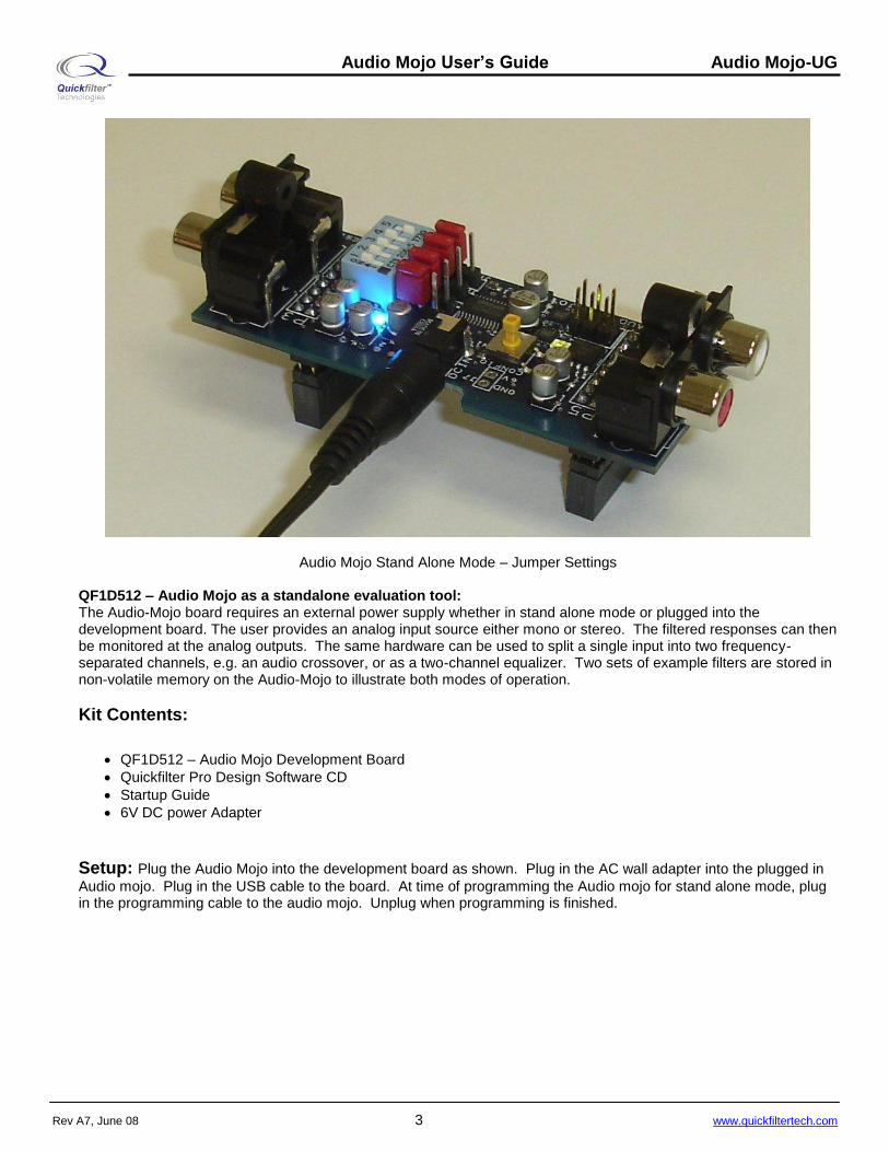
Audio Mojo Stand Alone Mode – Jumper Settings QF1D512 – Audio Mojo as a standalone evaluation tool: The Audio-Mojo board requires an external power supply whether in stand alone mode or plugged into the development board. The user provides an analog input source either mono or stereo. The filtered responses can then be monitored at the analog outputs. The same hardware can be used to split a single input into two frequency-separated channels, e.g. an audio crossover, or as a two-channel equalizer. Two sets of example filters are stored in non-volatile memory on the Audio-Mojo to illustrate both modes of operation.
Kit Contents:
QF1D512 – Audio Mojo Development Board
Quickfilter Pro Design Software CD
Startup Guide
6V DC power Adapter
Setup: Plug the Audio Mojo into the development board as shown. Plug in the AC wall adapter into the plugged in
Audio mojo. Plug in the USB cable to the board. At time of programming the Audio mojo for stand alone mode, plug in the programming cable to the audio mojo. Unplug when programming is finished.

Audio Mojo User’s Guide Audio Mojo-UG
Rev A7, June 08 4 www.quickfiltertech.com
Hardware: Dip Switch settings: The dip switch settings for SW2 are as follows:
Figure 1
Setting switches 1,2,3,4 all to on which is “0” is default 48kHz See table 1 above for 44.1kHz, 96kHz, or 192kHz selection Switch setting 5 determines left justify of the bit stream or I2S. For I2S have switch 5 set to off or “1”.
Switch 1: Push button The push button switch is used to select between configuration A and B. Two different configurations can be loaded into the Audio Mojo for stand alone mode. Typically configuration A which shows a green led lit is the corrected filter. Configuration B shows a red led lit which is typically used for a flat pass through response. By pushing SW1 repeatedly you can easily hear the difference between corrected audio and the original frequency response. Note: Switch 1 only works in stand alone mode. Although the LEDs toggle, in dev kit mode the audio is not routed through the on board QF1D512’s.

Audio Mojo User’s Guide Audio Mojo-UG
Rev A7, June 08 5 www.quickfiltertech.com
Jumper settings: Jumpers 1 through 4 are used for routing the digital audio in various configurations as in figure 2 below:
Jumper3
CoDEC in Loop back mode, Monitor no filtering
Jumper1
3 2 1
* = Default
Jumper2
QF1D512's running on Audio Mojo board
QF1D512's running on Audio Mojo and Dev Board
Jumper2 *
Jumper3
3 2 1
Jumper2
*
*
Jumper1
Jumper3
Jumper1
Jumper3
3 2 1
Jumper4
QF1D512's running on Dev Board
Jumper4
Jumper4
Jumper1
Jumper2
3 2 1
Jumper4
*
Figure 2
The two most common settings are: “1” Stand alone mode: All jumpers toward the dip switch SW2. This is used once filter configurations have been programmed into the audio mojo. “2” Dev kit mode: All jumpers away from the dip switch SW2. This is used for running the development board QF1D512s for fast changeable filters until the desired filter is designed. “3” Dev Kit and Dev board” allows four QF1D512’s to run in series. This can be useful for equalization of speakers on the Audio Mojo with spatialization or delay. “4” Is a loop back mode as a direct bypass mainly for used for trouble shooting connections. Jumper 4: This is the parallel serial jumper reserved for future upgrades. Currently this jumper should always be in serial mode which is set toward the dip switch SW2 in position 1 & 2.

Audio Mojo User’s Guide Audio Mojo-UG
Rev A7, June 08 6 www.quickfiltertech.com
Header J5 is used for the programming cable which goes between the development board and the Audio mojo. Pin 1 is closest to the LED’s.
Running a Cross Over example on the Audio Mojo connected to the QF1D512 development board: Step1: Make sure to download the latest QF1D512 software from Quickfilter’s website at www.quickfiltertech.com Version 2.1.0 Build 14 and up will give the correct software options. Once downloaded and installed run QFPro. The opening screen will show the following:
Step 2: Plug in the Audio Mojo to the QF1D512 development kit as shown on page 1. Next Plug in the USB cable and connect the Audio Mojo board to an audio source using the stereo RCA cables. Connect the output of the Audio Mojo board to an audio output device (speakers, headphones, a PC audio card AUX input, etc.) or an analysis tool (spectrum analyzer, oscilloscope, etc.) to review the results. An FFT display will also show the A/D results. Make sure Jumpers 1-4 are all in the 2-3 position on the Audio Mojo. Step 3: Select “Dual Serial” for the Target on the top of the screen. This way the first QF1D512 is used for the left channel, and the second QF1D512 is used for the right channel.

Audio Mojo User’s Guide Audio Mojo-UG
Rev A7, June 08 7 www.quickfiltertech.com
Step 4: Select “Audio-Mojo_DK” under the Data Input Source. Step 5: Select “Audio-Mojo-Left.q1d2” under Browse under Files from the right side of the screen. With the Chip “A” highlighted in green, double click the file to load the configuration into chip A. Step 6: Select “Audio-Mojo-Right.q1d2” under Browse under Files from the right side of the screen. With the Chip “B” highlighted in green, double click the file to load the configuration into chip B.
These configuration files were set at 48kHz which use uses SW2 settings 1-4 On, 5 Off. The sampling rate can be changed according to these switch settings. See Schematics at the end of this document for details. Step 7: Make sure the white noise source is running and a cable is going from the computers audio out jack into the IN RCA jacks of the Audio Mojo. Click the green “Start” Button.

Audio Mojo User’s Guide Audio Mojo-UG
Rev A7, June 08 8 www.quickfiltertech.com
The results are shown averaged in the FFT window. The Blue graph shows the 600Hz high pass and the Red Graph
shows the 800Hz low pass filter. By clicking the symbol, the FFT graph can be expanded to check and uncheck the averaging function. Once the system is running a new filter can be added or changed. These are shown as follows: Chip A Pin settings:

Audio Mojo User’s Guide Audio Mojo-UG
Rev A7, June 08 9 www.quickfiltertech.com
Chip B Pin Settings:
Data Format Settings for both A and B:

Audio Mojo User’s Guide Audio Mojo-UG
Rev A7, June 08 10 www.quickfiltertech.com
Running a Cross Over example on the Audio Mojo Stand alone mode: Once the desired filters are created and running on the development system, those filters can be programmed into the Atmel Tiny85 microcontroller running on the Audio Mojo by the following procedure: (Note there is a 501 tap limitation when running directly on the Audio Mojo) Step 1: Have a cable connected from the Quickfilter development board to the Audio Mojo as shown in the schematic at the end of this document. Step 2: Select File Export to External Host Step 3: Select Audio Mojo and load both Chip A and B configurations as follows.
Step 4: Select Download and wait until it shows Done. Step 5: Remove the Audio Mojo from the QF1D512 Kit, make sure jumpers 1-4 are in the 1-2 position. Step 6: Make sure DC power is applied through J7 or the DC jack. This can be 5-12VDC. Step 7: Toggle the settings on the Powered Audio Mojo by pressing SW1 configure switch. This will start the microcontroller running.

Audio Mojo User’s Guide Audio Mojo-UG
Rev A7, June 08 11 www.quickfiltertech.com
Contact Information:
Quickfilter Technologies, Inc. 1024 S. Greenville Avenue, Suite 100 Allen, TX 75002-3324
General: [email protected] Applications: [email protected] Sales: [email protected]
Phone: 214-547-0460 Fax: 214-547-0481
Web: http://www.quickfiltertech.com
The contents of this document are provided in connection with Quickfilter Technologies, Inc. products. Quickfilter makes no representations or warranties with respect to the accuracy or completeness of the contents of this publication and reserves the right to make changes to specifications and product descriptions at any time without notice. No license, whether express, implied, arising by estoppels or otherwise, to any intellectual property rights is granted by this publication. Except as set forth in Quickfilter's Standard Terms and Conditions of Sale, Quickfilter assumes no liability whatsoever, and disclaims any express or implied warranty, relating to its products including, but not limited to, the implied warranty of merchantability, fitness for a particular purpose, or infringement of any intellectual property right. Quickfilter's products are not designed, intended, authorized or warranted for use as components in systems intended for surgical implant into the body, or in other applications intended to support or sustain life, or in any other application in which the failure of Quickfilter's product could create a situation where personal injury, death, or severe property or environmental damage may occur. Quickfilter reserves the right to discontinue or make changes to its products at any time without notice.
© 2008 Quickfilter Technologies, Inc.
All rights reserved.
Quickfilter, the Quickfilter logo and combinations thereof, are trademarks of Quickfilter Technologies, Inc.
Other product names used in this publication are for identification purposes only and may be trademarks of their respective companies