PZ Line & PXL Operating & Service Manual
40
GARDNER DENVER ® 15-600 Version 12 April 2002 TRIPLEX SINGLE ACTING PUMP MODELS PZG – 7” PZH – 8” PZJ – 9” PZK – 10” PZL – 11” PXL – 11” OPERATING AND SERVICE MANUAL
description
pz line
Transcript of PZ Line & PXL Operating & Service Manual
GARDNER DENVER® 15-600Version 12April 2002
TRIPLEX
SINGLE ACTING PUMP
MODELS
PZG – 7”PZH – 8”PZJ – 9”PZK – 10”PZL – 11”PXL – 11”
OPERATING ANDSERVICE MANUAL
15-600 Page i
MAINTAIN PUMP RELIABILITY AND PERFORMANCE WITHGENUINE GARDNER DENVER
PARTS AND SUPPORT SERVICES
Gardner DenverR and OPIR genuine pump parts are manufactured to design tolerances and developed foroptimum dependability. Design and material innovations are the result of years of experience with hundreds ofdifferent pump applications. Reliability in materials and quality assurance are incorporated in our genuinereplacement parts.
Your authorized Gardner Denver and OPI distributor offers all the backup you’ll need. A worldwide networkof authorized distributors provides the finest product support in the pump industry.Your local authorized distributor maintains a large inventory of genuine parts and he is backed up for emergencyparts by direct access to the Gardner Denver Master Distribution Center (MDC) in Memphis, Tennessee.Your authorized distributor can support your Gardner Denver and OPI pump needs with these services:
1. Trained parts specialists to assist you in selecting the correct replacement parts.
2. Repair and maintenance kits designed with the necessary parts to simplify servicing your pump.
Authorized distributor service technicians are factory-trained and skilled in pump maintenance and repair. Theyare ready to respond and assist you by providing fast, expert maintenance and repair services.
For the location of your local authorized Gardner Denver and OPI distributor refer to the yellow pages ofyour phone directory or contact:
Distribution Center: Factory:Gardner Denver Gardner DenverMaster Distribution Center 1800 Gardner Expressway5585 East Shelby Drive Quincy, IL 62301Memphis, TN 38141 Phone: (217) 222-5400Phone: (901) 542-6100 Fax: (217) 224-7814Fax: (901) 542-6159
INSTRUCTIONS FOR ORDERING REPAIR PARTS
When ordering parts, specify Pump MODEL and SERIAL NUMBER (see nameplate on unit). The Serial Numberis also stamped on top of the cylinder end of the frame (cradle area).
All orders for Parts should be placed with the nearest authorized distributor.
Where NOT specified, quantity of parts required per pump or unit is one (1); where more than one is required perunit, quantity is indicated in parenthesis. SPECIFY EXACTLY THE NUMBER OF PARTS REQUIRED.DO NOT ORDER BY SETS OR GROUPS.
To determine the Right Hand and Left Hand side of a pump, stand at the power end and look toward the fluidend. Right Hand and Left Hand are indicated in parenthesis following the part name, i.e. (RH) & (LH), whenappropriate.
15-600 Page ii
FOREWORD
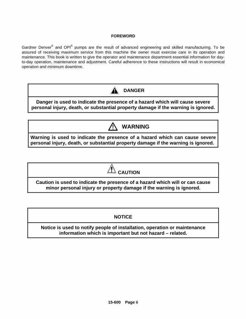
Gardner DenverR and OPIR pumps are the result of advanced engineering and skilled manufacturing. To beassured of receiving maximum service from this machine the owner must exercise care in its operation andmaintenance. This book is written to give the operator and maintenance department essential information for day-to-day operation, maintenance and adjustment. Careful adherence to these instructions will result in economicaloperation and minimum downtime.
DANGER
Danger is used to indicate the presence of a hazard which will cause severepersonal injury, death, or substantial property damage if the warning is ignored.
WARNING
Warning is used to indicate the presence of a hazard which can cause severepersonal injury, death, or substantial property damage if the warning is ignored.
CAUTION
Caution is used to indicate the presence of a hazard which will or can causeminor personal injury or property damage if the warning is ignored.
NOTICE
Notice is used to notify people of installation, operation or maintenanceinformation which is important but not hazard – related.
15-600 Page iii
TABLE OF CONTENTSMaintain Pump Reliability and Performance ..........................................................................................................i
Instructions For Ordering Repair Parts...................................................................................................................i
Foreword................................................................................................................................................................ ii
Index ..................................................................................................................................................................... iv
SECTION 1, Danger Notices................................................................................................................................ 1
SECTION 2, Installation & Operating Instructions................................................................................................ 7
SECTION 3, Routine Maintenance & Service Instructions................................................................................. 16
SECTION 4, Dimensions & Running Clearances............................................................................................... 28
LIST OF ILLUSTRATIONSFigure 1 Final Shimming ............................................................................................................................. 8
Figure 2 Crankcase Oil Requirements......................................................................................................... 9
Figure 3 Lubrication Schedule ..................................................................................................................... 9
Figure 4 Oil Capacities ........................................................................................................................... 10
Figure 5 Oil Filter Mounting ....................................................................................................................... 10
Figure 6 Sizes and Ratings - Models PZG and PZH.................................................................................12
Figure 7 Sizes and Ratings - Models PZJ and PZK .................................................................................. 13
Figure 8 Sizes and Ratings - Models PZL ................................................................................................. 14
Figure 9 Sizes and Ratings - Models PZL (High Pressure Fluid Cylinder)................................................ 14
Figure 10 Sizes and Ratings - Model PXL................................................................................................... 15
Figure 11 Jackshaft Bearing Installation...................................................................................................... 16
Figure 12 Jackshaft Removal/Installation Fixture........................................................................................ 16
Figure 13 Oil Seal Wear Sleeve Installation Tool ........................................................................................ 17
Figure 14 Connecting Rod Support ............................................................................................................. 18
Figure 15 Eccentric and Gear Assembly Support ....................................................................................... 19
Figure 16 Main Bearing Cartridge Lifting & Locating Devices..................................................................... 19
Figure 17 Table of Metric Equivalents for Dimensions (Inches).................................................................. 20
Figure 26 Installation of Push Rods............................................................................................................. 25
15-600 Page iv
INDEX
Maintain Pump Reliability And Performance ...............i
Ordering Repair Parts..................................................i
Foreword..................................................................... ii
SECTION 1................................................................ 1
Hammer Lug Fasteners............................................. 1
Valve Seat Pulling...................................................... 2
Hydraulic Puller.......................................................... 2
Wedge Puller ............................................................. 2
Covers And Guards ................................................... 2
Equipment Moving And Lifting................................... 2
Pressurized Pump Systems ...................................... 3
Flammable, Hot, Cold Or Corrosive Fluidpumping.... 4
High Pressure Liquid Jetting, Blasting And Cleaning 5
SECTION 2................................................................ 7
Start-Up ..................................................................... 7
Location ..................................................................... 7
Suction Line ............................................................... 8
Relief Valves.............................................................. 8
Surge Chamber ......................................................... 8
Starting A New Pump ................................................ 8
Lubrication ................................................................. 9
Oil Filter ................................................................... 10
Heat Exchanger ....................................................... 10
Direction Of Rotation ............................................... 10
Crosshead Drains .................................................... 11
Operation ................................................................. 11
Maintenance Schedule.............................................11
SECTION 3...............................................................16
Jackshaft ..................................................................16
Lube Oil Pump..........................................................18
Connecting Rods......................................................18
Eccentric And Gear AssemblyError! Bookmark not
defined.
Eccentric Cam Bearings...........................................20
Assembly Of Eccentric And Gear Assembly In Frame
..................................................................................21
Main Bearings...........................................................21
Crosshead Pins ........................................................24
Push Rods ................................................................24
Crossheads ..............................................................25
Crosshead Slides .....................................................25
Oil Stop Heads .........................................................25
Valve Chambers .......................................................25
Liner Clamp And Liners............................................26
Pistons......................................................................26
Piston Rod ................................................................26
Piston Washing System ...........................................26
Maintenance Of Valves ............................................26
Suction Strainer ........................................................27
SECTION 4...............................................................28
15-600 Page 1
SECTION 1DANGER NOTICES
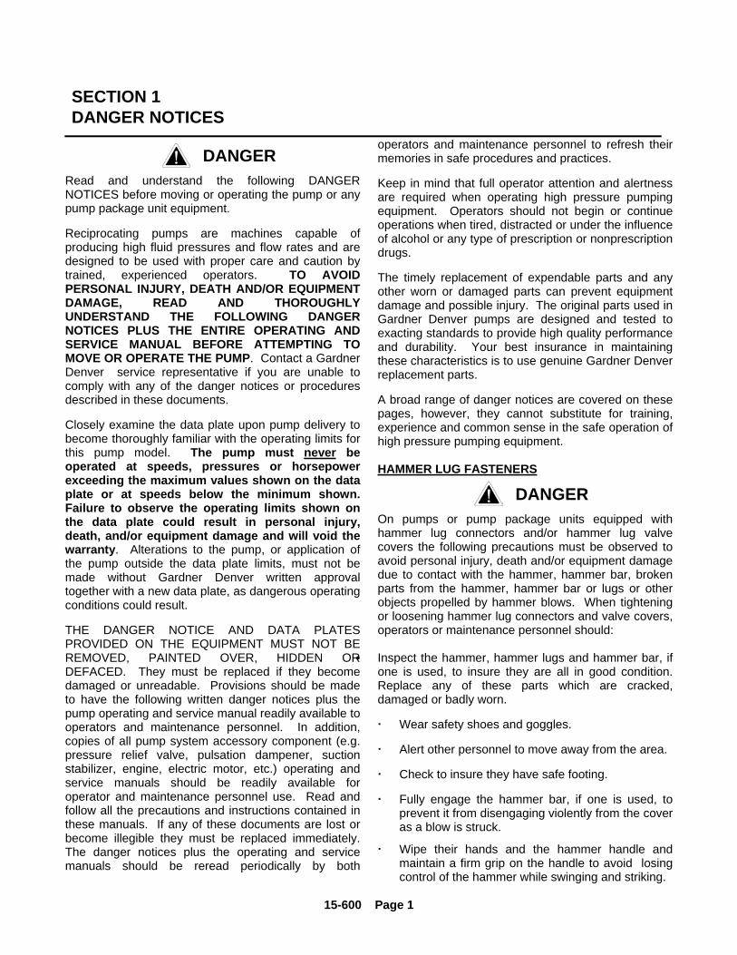
DANGERRead and understand the following DANGERNOTICES before moving or operating the pump or anypump package unit equipment.
Reciprocating pumps are machines capable ofproducing high fluid pressures and flow rates and aredesigned to be used with proper care and caution bytrained, experienced operators. TO AVOIDPERSONAL INJURY, DEATH AND/OR EQUIPMENTDAMAGE, READ AND THOROUGHLYUNDERSTAND THE FOLLOWING DANGERNOTICES PLUS THE ENTIRE OPERATING ANDSERVICE MANUAL BEFORE ATTEMPTING TOMOVE OR OPERATE THE PUMP. Contact a GardnerDenver service representative if you are unable tocomply with any of the danger notices or proceduresdescribed in these documents.
Closely examine the data plate upon pump delivery tobecome thoroughly familiar with the operating limits forthis pump model. The pump must never beoperated at speeds, pressures or horsepowerexceeding the maximum values shown on the dataplate or at speeds below the minimum shown.Failure to observe the operating limits shown onthe data plate could result in personal injury,death, and/or equipment damage and will void thewarranty. Alterations to the pump, or application ofthe pump outside the data plate limits, must not bemade without Gardner Denver written approvaltogether with a new data plate, as dangerous operatingconditions could result.
THE DANGER NOTICE AND DATA PLATESPROVIDED ON THE EQUIPMENT MUST NOT BEREMOVED, PAINTED OVER, HIDDEN ORDEFACED. They must be replaced if they becomedamaged or unreadable. Provisions should be madeto have the following written danger notices plus thepump operating and service manual readily available tooperators and maintenance personnel. In addition,copies of all pump system accessory component (e.g.pressure relief valve, pulsation dampener, suctionstabilizer, engine, electric motor, etc.) operating andservice manuals should be readily available foroperator and maintenance personnel use. Read andfollow all the precautions and instructions contained inthese manuals. If any of these documents are lost orbecome illegible they must be replaced immediately.The danger notices plus the operating and servicemanuals should be reread periodically by both
operators and maintenance personnel to refresh theirmemories in safe procedures and practices.
Keep in mind that full operator attention and alertnessare required when operating high pressure pumpingequipment. Operators should not begin or continueoperations when tired, distracted or under the influenceof alcohol or any type of prescription or nonprescriptiondrugs.
The timely replacement of expendable parts and anyother worn or damaged parts can prevent equipmentdamage and possible injury. The original parts used inGardner Denver pumps are designed and tested toexacting standards to provide high quality performanceand durability. Your best insurance in maintainingthese characteristics is to use genuine Gardner Denverreplacement parts.
A broad range of danger notices are covered on thesepages, however, they cannot substitute for training,experience and common sense in the safe operation ofhigh pressure pumping equipment.
HAMMER LUG FASTENERS
DANGEROn pumps or pump package units equipped withhammer lug connectors and/or hammer lug valvecovers the following precautions must be observed toavoid personal injury, death and/or equipment damagedue to contact with the hammer, hammer bar, brokenparts from the hammer, hammer bar or lugs or otherobjects propelled by hammer blows. When tighteningor loosening hammer lug connectors and valve covers,operators or maintenance personnel should:
• Inspect the hammer, hammer lugs and hammer bar, ifone is used, to insure they are all in good condition.Replace any of these parts which are cracked,damaged or badly worn.
Wear safety shoes and goggles.
Alert other personnel to move away from the area.
Check to insure they have safe footing.
Fully engage the hammer bar, if one is used, toprevent it from disengaging violently from the coveras a blow is struck.
Wipe their hands and the hammer handle andmaintain a firm grip on the handle to avoid losingcontrol of the hammer while swinging and striking.
15-600 Page 2
• Carefully swing the hammer to avoid strikingthemselves, another person and objects otherthan the targeted lugs or hammer bar.
• Avoid swinging the hammer above shoulderheight.
VALVE SEAT PULLING
DANGERThe following precautions must be observed byoperators and maintenance personnel to avoidpersonal injury, death and/or equipment damage fromcontact with the puller, hammer, wedge or brokenparts from these components when using either ahydraulic or wedge valve seat puller:
Hydraulic Puller
• Wear safety shoes and goggles.• Chain or tie the jack down as it will jump violently
when the valve seat disengages from the valvedeck.
• Check to insure the pressure applied by thehydraulic pump does not exceed the hydraulicram maximum pressure rating.
Wedge Puller
• Grind off any mushroomed material from thewedge before use.
• Follow the DANGER notices listed above in thehammer lug section, but substitute the termwedge for hammer lub an hammer bar.
COVERS AND GUARDS
DANGERAll pump covers must be securelyfastened in proper position at all timeswhen the pump is operating to avoidpersonal injury or death from movingparts. In addition, all moving parts onthe entire pump package, including butnot limited to, the engine or motors,drive shafts, belts, chains, pulleys,gears, etc., must be equipped withguards or covers, which must also besecurely fastened in proper position atall times when the equipment isoperating.
Covers and guards are intended to not only protectagainst personal injury or death, but to also protectthe equipment from damage from foreign objects.
EQUIPMENT MOVING AND LIFTING
DANGERHeavy equipment including pumps, pump packageunits and components should only be moved or liftedby trained, experienced operators, who are physicallyand mentally prepared to devote full attention andalertness to the moving and lifting operations. Anoperator should be fully aware of the use, capabilities,and condition of both the equipment being moved andthe equipment being used to move it.
DANGER
Failure to follow safe and proper pump,pump package or component lifting ormoving procedures can lead topersonal injury, death and/orequipment damage from shifting,falling or other unexpected oruncontrolled equipment movements.
Make sure the hoist, lift truck, ropes, slings, spreader,or other lifting equipment you are using is in goodcondition and has a rated lifting capacity equal to orgreater than the weight being lifted. Lifting devicesmust be checked frequently for condition andcontinued conformance to rated load capacity. Theyshould then be tagged with the inspected capacitytogether with the date of inspection.Fully assembled pumps and pump package units areheavy and should only be moved using the specifiedlifting lugs or attachments.
Many individual components have lifting eyes orlugs which must not be used to lift assemblies, asthey are designed to bear the weight of thecomponent only.
Before lifting the individual component check to insurethe lifting attachment is firmly secured to thecomponent with undamaged, properly torquedfasteners, sound welds, or other secure attachments.Examine the lifting eyes, lugs, slots, holes or otherprojections to insure they are not cracked, otherwisedamaged or badly worn. The repair of existing oraddition of new welded lifting eyes, lugs or otherprojections should only be performed by experienced,qualified welders.
Package units should be lifted with spreadersconnected to the lifting attachments normally built intothe package unit support skid. Packages too large tolift fully assembled should be separated into smaller
15-600 Page 3
loads. For these smaller loads the lifting devicesshould be fastened to the lifting attachments normallybuilt into the individual motor, engine, pump ortransmission/torque converter, or their separatesupport skids.
When lifting subassembled components, for examplea suction stabilizer attached to suction piping or adischarge pulsation dampener attached to a strainercross and piping, use special lifting slings designed tosafely support the combined weight of thecomponents. If a crane or hoist is being used to liftlarge components or assemblies, one or morepersons should assist the operator from the groundwith guide lines attached to the equipment beingmoved to properly position it and prevent uncontrolledmovement.
When you start to lift a pump, package unit,subassemblies or individual components and youobserve the equipment is tilting, or appearsunbalanced, lower the equipment and adjust the liftingdevice to eliminate these improper lifting conditionsbefore proceeding to move the equipment.
It is poor practice and dangerous to allow theequipment to pass over or close to your body orlimbs. Be prepared to move quickly out of danger ifequipment starts to fall, slip or move unexpectedlytoward you.
PRESSURIZED PUMP SYSTEMS
DANGERFluids under high pressure canpossess sufficient energy to causepersonal injury, death and/orequipment damage either throughdirect contact with escaping fluidstreams or by contact with looseobjects the pressurized fluid propels.
Operating a pump against a blocked or restricteddischarge line can produce excessive pressures inthe entire discharge system, which can damage orburst discharge system components.
DANGERNever operate a pump without aproperly sized pressure relief valvelocated in the flowing discharge lineimmediately adjacent to the pumpdischarge connection.
The relief valve should be placed in the flowingdischarge line and not at the opposite end of thedischarge manifold in a dead end connection. Thedead end may become clogged with solid materialcarried in the fluid, which could prevent proper reliefvalve operation.
DANGER
Never place a shut-off valve or anyother component between the pumpdischarge connection and the pressurerelief valve.
Make sure the pressure relief valve is installed so anypressurized relief discharge from the valve is directedaway from possible contact with people or equipment.The relief valve must be set to relieve at a pressureequal to or below the maximum pressure valuesshown on the pump data plate. However, if acomponent is used in the discharge system with alower rated pressure capability than that listed on thepump data plate, the pressure relief valve must be setto relief valve must be set to relieve at a pressureequal to or below the rated capability of the lowestrated component.
Before starting the pump every time, check toinsure:
• The pressure relief valve is in good operatingcondition and has been set to the proper reliefpressure.
• Any pipe line used to direct pressurized relief flow toanother location, such as a collecting tank, is notblocked.
• The discharge system is not blocked and all thedischarge line valves are open.
Check all fluid end discharge system componentsincluding pipe, connections, elbows, threads,fasteners, hoses, etc., at least once every sixmonths to confirm their structural adequacy. Withtime, wear, corrosion and fatigue can reduce thestrength of all components. Magnetic iron and steelcomponents should be checked with magnetic particleor dye penetrate crack detection equipment.Nonmagnetic materials should be checked for crackswith dye penetrants. All metallic components shouldalso be visually checked during these inspections forsigns of corrosion. If a component shows evidence ofcracking or loss of material due to corrosion it must bereplaced with a new part.
Continually monitor suction and discharge hoseassemblies when the pump is operating for leakage,kinking, abrasion, corrosion or any other signs of wearor damage.
15-600 Page 4
Worn or damaged hose assemblies should bereplaced immediately. At least every six monthsexamine hose assemblies internally for cut or bulgedtube, obstructions and cleanliness. For segment stylefittings, be sure that the hose butts up against thenipple shoulder, the band and retaining ring areproperly set and tight and the segments are properlyspaced. Check for proper gap between nut andsocket or hex and socket. Nuts should swivel freely.Check the layline of the hose to be sure that theassembly is not twisted. Cap the ends of the hosewith plastic covers to keep them clean until they aretested or reinstalled on the pump unit. Following thisvisual examination, the hose assembly should behydrostatically tested, on test stands having adequateguards to protect the operator, per the hosemanufacturer’s proof test procedure.
Fluid end component inspections should beperformed more frequently than every six monthsif pressures above 2,500 PSI are used in thedischarge system or if corrosive, flammable orhot (over 110º F) fluids are being pumped.
Proper stuffing box packing selection is important forsafe pump operation. Contact a Gardner Denverservice representative for assistance in selecting theproper packing before beginning operation.
Before starting the pump the first time and periodicallythereafter check the pump, suction and dischargesystem fastener torques versus the values listed onpage 12 to insure proper tightness. Over and undertorquing can damage threaded pipes, connectionsand fasteners, which may lead to component damageand/or failure. Replace all components found to bedamaged or defective. On pumps equipped withstuffing boxes, the gland must be engaged by at leastthree (3) threads to hold the discharge pressure of thepump.
Block the crankshaft from turning and make certainthat all pump drive motor or engine start switches orstarter controls are clearly tagged with warnings not tostart the pump while repair work is in process.
DANGERDo not attempt to service, repair, oradjust the plunger packing or otherwisework on the pump while the unit isoperating. Shut off the pump drivemotor or engine and relieve the fluidpressure in the pump suction anddischarge systems before any work orinvestigation is performed on the pumpor pump systems.
Whenever the pump is operating, continually monitorthe entire suction, discharge and pump lubricatingsystems for leaks. Thoroughly investigate the causefor leakage and do not operate the pump until thecause of the leak has been corrected. Replace anyparts which are found to be damaged or defective.When a gasketed joint is disassembled for anyreason, discard the used gasket and replace it with anew, genuine Gardner Denver gasket beforereassembling the joint.
Due to the high working pressures contained by thefluid cylinder, discharge manifold and dischargepiping, welding on these components is notrecommended. If welding on the discharge systemcannot be avoided, only experienced, qualifiedwelders should be used. In addition, the welded partshould be hydrostatically proof tested in the shop withwater or hydraulic fluid to one and one half timesmaximum discharge system working pressure, withno observable fluid leakage, before the part isreinstalled in the pump system.
In summary, high pressure fluid streams can possesssufficient energy to cause personal injury, deathand/or equipment damage. These results can occureither through direct contact with the fluid stream orby contact with loose objects the fluid stream haspropelled, if the pump system is improperly used, or ifthe fluid is misdirected, or allowed to escape fromdefective or improperly maintained equipment.
FLAMMABLE, HOT, COLD OR CORROSIVE FLUIDPUMPING
DANGERExtreme caution must be exercised bytrained and experienced operatorswhen flammable, hot, cold or corrosivefluids are being pumped in order toavoid personal injury, death and/orequipment damage due to explosion,fire, burn, extreme cold or chemicalattack.
Never operate a pump which is pumpinghydrocarbons or other flammable, hot, cold, orcorrosive fluids when any part of the pump, suctionsystem or discharge system is leaking. Stop thepump immediately if any leakage, other than a fewdrops per minute of packing weepage, is observed.Keep all flame, sparks, or hot objects away from anypart of the pump, suction system, or dischargesystem. Shield the pump, suction system anddischarge system to prevent any flammable, hot, cold
15-600 Page 5
or corrosive fluid leakage from dripping or spraying onany components, flame, sparks, hot objects or people.Inspect the plungers, packing, gaskets and seals forfluid leakage frequently and replace all worn or leakingparts.
Selection of the proper gaskets, seals and stuffing boxpacking is even more critical when flammable, hot, coldor corrosive fluids are being pumped than when other,inherently less dangerous fluids are used. Contact aGardner Denver service representative for assistancein selecting the proper gaskets, seals and packingbefore beginning operation.
Since some packing weepage into the cradle area isinevitable, the drain at the bottom of the cradle must beconnected to a drain line which conducts the fluidleakage to a collection container located in a protectedarea. The entire drain system and container must beconstructed of materials resistant to attack from thepumped fluid or from explosion or fire of the pumpedfluid.
Heavy duty cradle covers must be securelyfastened in the proper position on the pump at alltimes when the pump is operating. If the pumpedfluid releases harmful, explosive or flammablevapors the covers must be vented to conduct thefumes away from the pump unit to a nonhazardousarea.
Before beginning pumping operations or starting thepump power source (whether an engine or electricmotor) check the atmosphere all around the pumpingsite for the presence of flammable or explosive vapors.Do not begin operation and stop ongoing operation ifflammable or explosive vapors are detected. Hotsurfaces, sparks, electric current or engine exhaustcould ignite flammable or explosive vapors. Eachengine used as a power source on pumping unitswhere flammable or explosive vapors could formshould be equipped with an air inlet shut-off. Ifflammable or explosive vapors are present in thepumping site atmosphere, an engine could continue torun on these vapors even after the engine fuel line isshut-off if an air inlet shut-off is not used.
In addition, on pumping units used where flammable orexplosive vapors could form, all electric motors usedas power sources must be of explosion proofconstruction and all electrical components and wiringmust meet the current National Electrical Code forexplosive atmospheres.
These precautions must be taken to avoid possiblepersonal injury, death and/or equipment damage fromexplosion, fire or burns.
HIGH PRESSURE LIQUID JETTING, BLASTINGAND CLEANING
DANGERExtreme caution must be exercised ifany type of wand, gun, nozzle or anyother pressure and flow directingdevice is attached to the pumpdischarge system for use in jetting,blasting, cleaning, etc. This type ofequipment must be used with utmostcare by trained, experienced operators.High pressure fluid streams can eitherby direct contact or by propelling looseobjects, cause serious personal injuryor death to the operators and/or otherpersons.
Pressure or flow directing devices often receivepressurized flow through flexible hoses, which canburst if they are kinked, cut, abraded or are otherwiseworn, damaged or pressured above their ratedcapacity. Protect the hose and connections fromdamage by people, objects and vehicles. A broken,cut or otherwise burst hose can release pressurizedfluid which may cause personal injury, death and/orequipment damage.
High pressure fluid from hand held or hand directedpressure and flow directing devices may overpower anoperator’s ability to control or direct the device, whichcould lead to personal injury, death and/or equipmentdamage. The operator must brace against thebackward thrust of a hand held device. In addition, asafety harness or safety net must be used whenworking in an area where the operator could be injuredin a fall. Stand to the side of any tubing or containerbeing sprayed to avoid back spray and never operate ahand held device above shoulder level.
Never direct the pressurized fluid stream at yourself orany other person, control valves, the pump, pumpdrive, suction or discharge systems. The pressurizedstream can cause serious personal injury or death andcan also change valve or control settings which coulddangerously increase the delivery pressure to thepressure and flow directing device.
When operating a pressure and flow directing device,use only equipment which automatically shuts off flowwhen an operator releases hand or foot pressure onthe pressurized flow trigger control to prevent injury ifthe operator is overpowered or becomes disabled.
15-600 Page 6
Check to insure this automatic shut-off equipment isoperating properly before every use and nevercircumvent the automatic shut-off for any reason or byany means when operating the equipment.
When operating any type of high pressure liquidjetting, blasting or cleaning devices the operatorsmust always wear protective clothing including, butnot limited to, a hard hat with full face visor, heavyduty rain coat and pants, boots with nonskid sole andsafety toe, rubber gloves with rough grip surface andear noise protection.
Full operator attention and alertness are requiredwhen operating this equipment to avoid personalinjury, death and/or equipment damage. Theoperators should take frequent rest breaks and ceaseoperations when they become tired or distracted.
Before the equipment is started, the work area mustbe inspected and properly prepared to avoid personalinjury, death and/or damage to equipment. Makesure the work area is checked for hazardous fumes,has adequate ventilation for engine exhaust andsufficient drainage for released fluid. Check the workarea for electrical equipment, connections, outlets,fixtures, or lines. If any are present they must bemade water tight and the electrical power to thesedevices must be shut off to avoid electrical shocksfrom fluid contact. The work area should be clearlymarked and roped off to keep unauthorized peopleand vehicles from entering. Remove all loose parts,tools and equipment from the work area beforebeginning operation.
All pressure containing devices including wands,nozzles, guns, hoses, connections, etc., should beregularly checked for condition. These componentsshould all be tagged with their tested pressurecapabilities together with the date testing wasperformed. Always be aware of the pressure levelin the system and never connect any equipmentto the system which has a rated or testedpressure capability below the system operatingpressure.
The equipment must be shut down and the systempressure released before changing or disconnectingwands, nozzles, guns, hoses, connections or anyother pressurized system components.
All pressure containing devices including wands,nozzles, guns, connections, etc., plus all automaticshut-off, pressure and control equipment should betreated with care. Protect them from damage bypeople, objects and vehicles. Never lay them in dirt,mud, ice or other loose material which could plug thefluid opening or interfere with their operation. Neveruse the wand, nozzle, gun, etc. to pry loose materialoff items being cleaned.
Before starting operation in a cold environment, checkto make sure there is no ice in the fluid system andrepeat this inspection each time before operation isrestarted.
Before purchasing wands, nozzles, guns,connections, and hose, etc., manufacturers of thesecomponents should be contacted for detailedinformation on the design and safety featuresincorporated in their products. After careful study ofvarious manufacturers products, we recommend thatonly those wands, nozzles, guns, connections andhose, etc., be considered for purchase that you judgeto offer the highest quality of design, construction andsafety, since these components are among the mostcritical to the safe operation of high pressure liquidjetting, blasting and cleaning equipment.
After you have selected and purchased thesecomponents, follow the manufacturer’s instructionscompletely in their use.
In summary, high pressure jetting, blasting andcleaning are inherently dangerous, as thepressures and flow rates needed to remove scale,clean, etc. are sufficient to cause personal injury,death and/or equipment damage resulting from,but not limited to, any of the conditions describedin the above Danger Notices.
15-600 Page 7
SECTION 2INSTALLATION & OPERATING INSTRUCTIONS
FOR GARDNER DENVER PZ SERIES & PXL SINGLE ACTING POWER PUMPS
Reference to Parts List covering the Model Pump being serviced is recommended in connection with thisInstruction Manual.
Repair Parts Lists with Sectional Views are available from any Gardner Denver Sales and ServiceOffice. When ordering parts, always give size and serial number of pump. Always use genuine GardnerDenver parts. For efficient, factory-trained service, consult a Gardner Denver Service Specialist.
START-UP – Pumps are shipped from the factorywithout oil in the crankcase. The hood should beremoved and the power end examined and cleaned ifnecessary. The pump may have been in storage or inthe yard for sometime and as a consequence dirt mayhave entered the crankcase. Parts may have beenrobbed from the pump during storage and notreplaced. All nuts and screws should be tightened.
Be sure all valves in the discharge line are open. Novalve should be installed between the pump andpressure relief valve in discharge line.
To prevent excessive wear on the fluid pistons andpacking when starting, remove a suction valve coverplate on each side of the fluid end and prime the pump.Pump should be started slowly, if possible, and shouldbe operated for several hours with practically nodischarge pressure. Check oil level as it may benecessary to add a small quantity of oil to compensatefor that adhering to the walls of the crankcase themoving parts. The pump may then gradually bebrought up to full speed and full working pressure.Watch for undue heating or abnormal noise in theworking parts. Check all joints in the suction line to besure there are no air leaks.
DANGER
When working on any pump, be certainthere is no fluid pressure on either thesuction or discharge side. Pressure onthe fluid end might move the pump andcause damage or injury to personnel. Itis recommended that all suction valvecovers be removed to avoid fluidpressure building up against the pistonsor plungers.
DANGER
If the drive is not to be removed, it isrecommended that the air line to theclutch be disconnected to preventaccidental starting of the pump.
LOCATION - Pump should be set level and solidlysupported. The drive should be accurately aligned.Pump should be placed as close to the slush pit aspossible to keep the suction line short and direct.Locate pump as low as possible to maintain aminimum suction lift to the centrifugal charging pumpwhich is used because of the high speed of this type ofmud pump.When the pump skid or master skid is to be bolted orwelded to a platform or deck in the field, it is necessarythat the following “Final Shimming Procedure” befollowed.
Final Shimming Procedure - After the pump skid ormaster skid has been bolted or welded to a stationaryplatform or deck, proceed as follows:
a. Remove the cap screws used to secure the pumpframe to its skid.
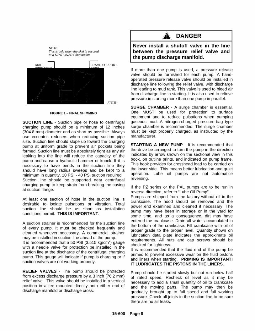
b. At each foot where a space exists between footand skid, place a dial indicator on the frame footand skid as shown in FIGURE 1. Set dial toZERO.
c. Place shims between frame foot and skid wherespace exists so the dial indicator shows the framehas been raised approximately .005 to .010inches (.126 to .254 mm).
d. Securely tighten the frame to skid cap screws. Ifthe proper number of shims were used, the dialindicator should return to within +/-.003 inches(.076 mm) of zero. If not, repeat the procedurechanging number of shims used.
15-600 Page 8
NOTE:This is only when the skid is secured to a STATIONARY foundation.
DIALINDICATOR
FRAME SUPPORT FOOT
SHIM
A75738
FIGURE 1 – FINAL SHIMMING
SUCTION LINE - Suction pipe or hose to centrifugalcharging pump should be a minimum of 12 inches(304.8 mm) diameter and as short as possible. Alwaysuse eccentric reducers when reducing suction pipesize. Suction line should slope up toward the chargingpump at uniform grade to prevent air pockets beingformed. Suction line must be absolutely tight as any airleaking into the line will reduce the capacity of thepump and cause a hydraulic hammer or knock. If it isnecessary to have bends in the suction line theyshould have long radius sweeps and be kept to aminimum in quantity. 10 PSI - 40 PSI suction required.Suction line should be supported near centrifugalcharging pump to keep strain from breaking the casingat suction flange.
At least one section of hose in the suction line isdesirable to isolate pulsations or vibration. Totalsuction line should be as short as installationconditions permit. THIS IS IMPORTANT.
A suction strainer is recommended for the suction lineof every pump. It must be checked frequently andcleaned whenever necessary. A commercial strainermay be installed in suction line ahead of the pump.It is recommended that a 50 PSI (3.515 kg/cm2) gaugewith a needle valve for protection be installed in thesuction line at the discharge of the centrifugal chargingpump. This gauge will indicate if pump is charging or ifsuction valves are not working properly.
RELIEF VALVES - The pump should be protectedfrom excess discharge pressure by a 3 inch (76.2 mm)relief valve. This valve should be installed in a verticalposition in a tee mounted directly onto either end ofdischarge manifold or discharge cross.
DANGERNever install a shutoff valve in the linebetween the pressure relief valve andthe pump discharge manifold.
If more than one pump is used, a pressure releasevalve should be furnished for each pump. A hand-operated pressure release valve should be installed indischarge line following the relief valve, with dischargeline leading to mud tank. This valve is used to bleed airfrom discharge line in starting. It is also used to relievepressure in starting more than one pump in parallel.
SURGE CHAMBER - A surge chamber is essential.One MUST be used for protection to surfaceequipment and to reduce pulsations when pumpinggaseous mud. A nitrogen-charged pressure-bag typesurge chamber is recommended. The surge chambermust be kept properly charged, as instructed by themanufacturer.
STARTING A NEW PUMP - It is recommended thatthe drive be arranged to turn the pump in the directionindicated by arrow shown on the sectional view in thisbook, on outline prints, and indicated on pump frame.This book provides for crosshead load to be carried onthe lower side. This means better lubrication and quietoperation. Lube oil pumps are not automaticereversing.
If the PZ series or the PXL pumps are to be run inreverse direction, refer to “Lube Oil Pump”.Pumps are shipped from the factory without oil in thecrankcase. The hood should be removed and thepower end examined and cleaned if necessary. Thepump may have been in storage or in the yard forsome time, and as a consequence, dirt may haveentered the crankcase. Drain all water accumulated inthe bottom of the crankcase. Fill crankcase with oil ofproper grade to the proper level. Quantity shown onlubrication data plate indicates the approximate oilrequirements. All nuts and cap screws should bechecked for tightness.It is recommended that the fluid end of the pump beprimed to prevent excessive wear on the fluid pistonsand liners when starting. PRIMING IS IMPORTANT!IT LUBRICATES THE PISTONS IN THE LINERS.
Pump should be started slowly but not run below halfof rated speed. Recheck oil level as it may benecessary to add a small quantity of oil to crankcaseand the moving parts. The pump may then begradually brought up to full speed and full workingpressure. Check all joints in the suction line to be surethere are no air leaks.
15-600 Page 9
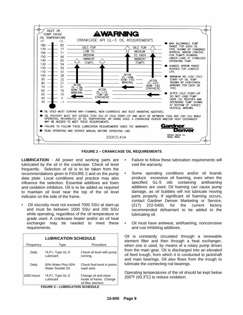
FIGURE 2 – CRANKCASE OIL REQUIREMENTS
LUBRICATION - All power end working parts arelubricated by the oil in the crankcase. Check oil levelfrequently. Selection of oil is to be taken from therecommendations given in FIGURE 2 and on the pumpdata plate. Local conditions and practice may alsoinfluence the selection. Essential additives are foamand oxidation inhibitors. Oil is to be added as requiredto maintain oil level near the top of the oil levelindicator on the side of the frame.
• Oil viscosity must not exceed 7000 SSU at start-upand must be between 1500 SSU and 200 SSUwhile operating, regardless of the oil temperature orgrade used. A crankcase heater and/or an oil heatexchanger may be needed to meet theserequirements.
LUBRICATION SCHEDULEFrequency Type Procedure
Daily *A.P.I. Type GL-5Lubricant
Check oil level with pumprunning.
Daily 50% Water Plus 50%Water Soluble Oil
Check fluid level in pistonwash tank.
1000 Hours *A.P.I. Type GL-5Lubricant
Change oil and cleaninside of frame. Changeoil filter element.
FIGURE 3 – LUBRICATION SCHEDULE
• Failure to follow these lubrication requirements willvoid the warranty.
• Some operating conditions and/or oil brandsproduce excessive oil foaming, even when thespecified GL-5 oils containing antifoamingadditives are used. Oil foaming can cause pumpdamage, as oil bubbles will not lubricate movingparts properly. If significant oil foaming occurs,contact Gardner Denver Marketing or Service,(217) 222-5400, for the current factoryrecommended defoamant to be added to thelubricating oil.
• Oil must have antiwear, antifoaming, noncorrosiveand rust inhibiting additives.
Oil is constantly circulated through a renewableelement filter and then through a heat exchanger,when one is used, by means of a rotary pump drivenfrom the main gear. Oil is discharged into an elevatedoil feed trough, from which it is conducted to jackshaftand main bearings. Oil also flows from the trough tolubricate the connecting rod bearings.
Operating temperatures of the oil should be kept below200oF (93.3oC) to reduce oxidation.
15-600 Page 10
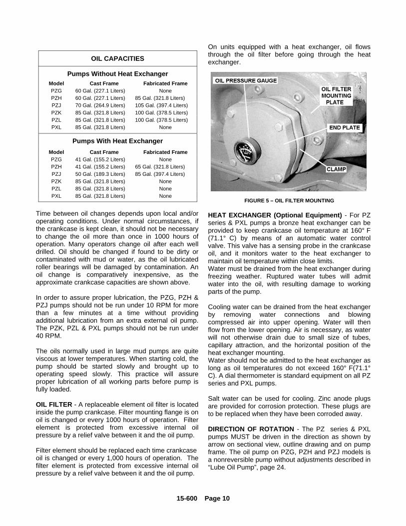
OIL CAPACITIES
Pumps Without Heat ExchangerModel Cast Frame Fabricated FramePZG 60 Gal. (227.1 Liters) NonePZH 60 Gal. (227.1 Liters) 85 Gal. (321.8 Liters)PZJ 70 Gal. (264.9 Liters) 105 Gal. (397.4 Liters)PZK 85 Gal. (321.8 Liters) 100 Gal. (378.5 Liters)PZL 85 Gal. (321.8 Liters) 100 Gal. (378.5 Liters)PXL 85 Gal. (321.8 Liters) None
Pumps With Heat ExchangerModel Cast Frame Fabricated FramePZG 41 Gal. (155.2 Liters) NonePZH 41 Gal. (155.2 Liters) 65 Gal. (321.8 Liters)PZJ 50 Gal. (189.3 Liters) 85 Gal. (397.4 Liters)PZK 85 Gal. (321.8 Liters) NonePZL 85 Gal. (321.8 Liters) NonePXL 85 Gal. (321.8 Liters) None
Time between oil changes depends upon local and/oroperating conditions. Under normal circumstances, ifthe crankcase is kept clean, it should not be necessaryto change the oil more than once in 1000 hours ofoperation. Many operators change oil after each welldrilled. Oil should be changed if found to be dirty orcontaminated with mud or water, as the oil lubricatedroller bearings will be damaged by contamination. Anoil change is comparatively inexpensive, as theapproximate crankcase capacities are shown above.
In order to assure proper lubrication, the PZG, PZH &PZJ pumps should not be run under 10 RPM for morethan a few minutes at a time without providingadditional lubrication from an extra external oil pump.The PZK, PZL & PXL pumps should not be run under40 RPM.
The oils normally used in large mud pumps are quiteviscous at lower temperatures. When starting cold, thepump should be started slowly and brought up tooperating speed slowly. This practice will assureproper lubrication of all working parts before pump isfully loaded.
OIL FILTER - A replaceable element oil filter is locatedinside the pump crankcase. Filter mounting flange is onoil is changed or every 1000 hours of operation. Filterelement is protected from excessive internal oilpressure by a relief valve between it and the oil pump.
Filter element should be replaced each time crankcaseoil is changed or every 1,000 hours of operation. Thefilter element is protected from excessive internal oilpressure by a relief valve between it and the oil pump.
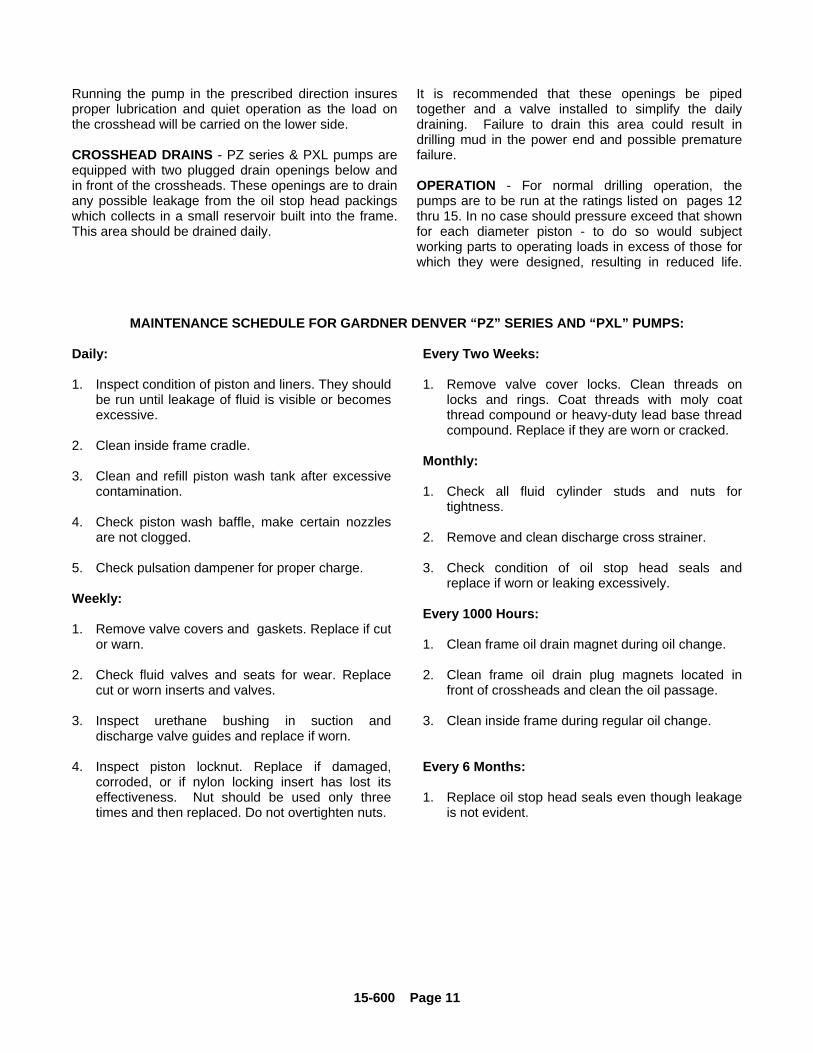
On units equipped with a heat exchanger, oil flowsthrough the oil filter before going through the heatexchanger.
FIGURE 5 – OIL FILTER MOUNTING
HEAT EXCHANGER (Optional Equipment) - For PZseries & PXL pumps a bronze heat exchanger can beprovided to keep crankcase oil temperature at 160° F(71.1° C) by means of an automatic water controlvalve. This valve has a sensing probe in the crankcaseoil, and it monitors water to the heat exchanger tomaintain oil temperature within close limits.Water must be drained from the heat exchanger duringfreezing weather. Ruptured water tubes will admitwater into the oil, with resulting damage to workingparts of the pump.
Cooling water can be drained from the heat exchangerby removing water connections and blowingcompressed air into upper opening. Water will thenflow from the lower opening. Air is necessary, as waterwill not otherwise drain due to small size of tubes,capillary attraction, and the horizontal position of theheat exchanger mounting.Water should not be admitted to the heat exchanger aslong as oil temperatures do not exceed 160° F(71.1°C). A dial thermometer is standard equipment on all PZseries and PXL pumps.
Salt water can be used for cooling. Zinc anode plugsare provided for corrosion protection. These plugs areto be replaced when they have been corroded away.
DIRECTION OF ROTATION - The PZ series & PXLpumps MUST be driven in the direction as shown byarrow on sectional view, outline drawing and on pumpframe. The oil pump on PZG, PZH and PZJ models isa nonreversible pump without adjustments described in“Lube Oil Pump”, page 24.
15-600 Page 11
Running the pump in the prescribed direction insuresproper lubrication and quiet operation as the load onthe crosshead will be carried on the lower side.
CROSSHEAD DRAINS - PZ series & PXL pumps areequipped with two plugged drain openings below andin front of the crossheads. These openings are to drainany possible leakage from the oil stop head packingswhich collects in a small reservoir built into the frame.This area should be drained daily.
It is recommended that these openings be pipedtogether and a valve installed to simplify the dailydraining. Failure to drain this area could result indrilling mud in the power end and possible prematurefailure.
OPERATION - For normal drilling operation, thepumps are to be run at the ratings listed on pages 12thru 15. In no case should pressure exceed that shownfor each diameter piston - to do so would subjectworking parts to operating loads in excess of those forwhich they were designed, resulting in reduced life.
MAINTENANCE SCHEDULE FOR GARDNER DENVER “PZ” SERIES AND “PXL” PUMPS:
Daily:
1. Inspect condition of piston and liners. They shouldbe run until leakage of fluid is visible or becomesexcessive.
2. Clean inside frame cradle.
3. Clean and refill piston wash tank after excessivecontamination.
4. Check piston wash baffle, make certain nozzlesare not clogged.
5. Check pulsation dampener for proper charge.
Weekly:
1. Remove valve covers and gaskets. Replace if cutor warn.
2. Check fluid valves and seats for wear. Replacecut or worn inserts and valves.
3. Inspect urethane bushing in suction anddischarge valve guides and replace if worn.
4. Inspect piston locknut. Replace if damaged,corroded, or if nylon locking insert has lost itseffectiveness. Nut should be used only threetimes and then replaced. Do not overtighten nuts.
Every Two Weeks:
1. Remove valve cover locks. Clean threads onlocks and rings. Coat threads with moly coatthread compound or heavy-duty lead base threadcompound. Replace if they are worn or cracked.
Monthly:
1. Check all fluid cylinder studs and nuts fortightness.
2. Remove and clean discharge cross strainer.
3. Check condition of oil stop head seals andreplace if worn or leaking excessively.
Every 1000 Hours:
1. Clean frame oil drain magnet during oil change.
2. Clean frame oil drain plug magnets located infront of crossheads and clean the oil passage.
3. Clean inside frame during regular oil change.
Every 6 Months:
1. Replace oil stop head seals even though leakageis not evident.
15-600 Page 12
Cylinder Displacement
Qty. Diameter StrokeMaximumPressure Piston Load
Inches mm Inches mmGal. Per
Rev.Liter Per
Rev.Gal. Per
Min.Liter Per
Min. PSI kg/cm2 Pounds kgPumpRPM
Jack-shaftRPM
InputHP
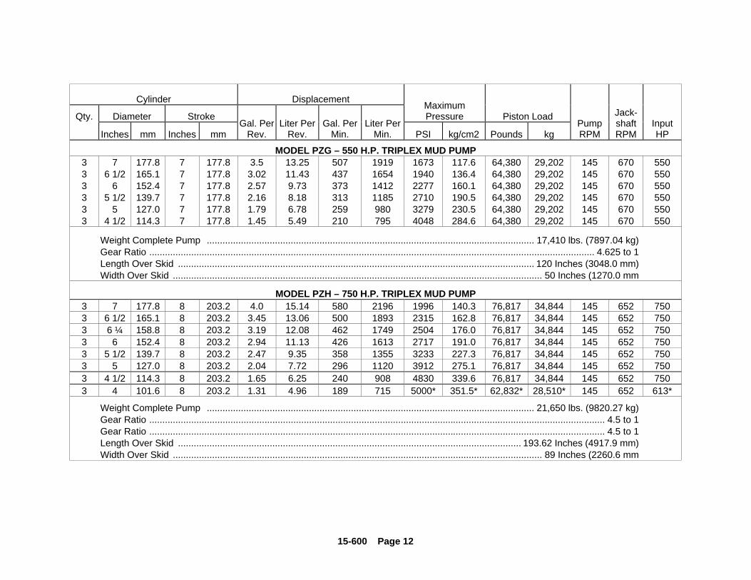
MODEL PZG – 550 H.P. TRIPLEX MUD PUMP3 7 177.8 7 177.8 3.5 13.25 507 1919 1673 117.6 64,380 29,202 145 670 5503 6 1/2 165.1 7 177.8 3.02 11.43 437 1654 1940 136.4 64,380 29,202 145 670 5503 6 152.4 7 177.8 2.57 9.73 373 1412 2277 160.1 64,380 29,202 145 670 5503 5 1/2 139.7 7 177.8 2.16 8.18 313 1185 2710 190.5 64,380 29,202 145 670 5503 5 127.0 7 177.8 1.79 6.78 259 980 3279 230.5 64,380 29,202 145 670 5503 4 1/2 114.3 7 177.8 1.45 5.49 210 795 4048 284.6 64,380 29,202 145 670 550
Weight Complete Pump ............................................................................................................................. 17,410 lbs. (7897.04 kg)Gear Ratio .......................................................................................................................................................................... 4.625 to 1Length Over Skid ........................................................................................................................................ 120 Inches (3048.0 mm)Width Over Skid ............................................................................................................................................. 50 Inches (1270.0 mm
MODEL PZH – 750 H.P. TRIPLEX MUD PUMP3 7 177.8 8 203.2 4.0 15.14 580 2196 1996 140.3 76,817 34,844 145 652 7503 6 1/2 165.1 8 203.2 3.45 13.06 500 1893 2315 162.8 76,817 34,844 145 652 7503 6 ¼ 158.8 8 203.2 3.19 12.08 462 1749 2504 176.0 76,817 34,844 145 652 7503 6 152.4 8 203.2 2.94 11.13 426 1613 2717 191.0 76,817 34,844 145 652 7503 5 1/2 139.7 8 203.2 2.47 9.35 358 1355 3233 227.3 76,817 34,844 145 652 7503 5 127.0 8 203.2 2.04 7.72 296 1120 3912 275.1 76,817 34,844 145 652 7503 4 1/2 114.3 8 203.2 1.65 6.25 240 908 4830 339.6 76,817 34,844 145 652 7503 4 101.6 8 203.2 1.31 4.96 189 715 5000* 351.5* 62,832* 28,510* 145 652 613*
Weight Complete Pump ............................................................................................................................. 21,650 lbs. (9820.27 kg)Gear Ratio .............................................................................................................................................................................. 4.5 to 1Gear Ratio .............................................................................................................................................................................. 4.5 to 1Length Over Skid ................................................................................................................................... 193.62 Inches (4917.9 mm)Width Over Skid ............................................................................................................................................. 89 Inches (2260.6 mm
15-600 Page 13
Cylinder Displacement
Qty. Diameter StrokeMaximumPressure Piston Load
Inches mm Inches mmGal. Per
Rev.Liter Per
Rev.Gal. Per
Min.Liter Per
Min. PSI kg/cm2 Pounds kgPumpRPM
Jack-shaftRPM
InputHP
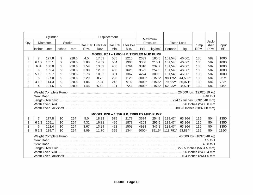
MODEL PZJ – 1,000 H.P. TRIPLEX MUD PUMP3 7 177.8 9 228.6 4.5 17.03 585 2215 2639 185.5 101,548 46,061 130 582 10003 6 1/2 165.1 9 228.6 3.88 14.69 504 1908 3060 215.1 101,548 46,061 130 582 10003 6 ¼ 158.8 9 228.6 3.59 13.59 466 1764 3310 232.7 101,548 46,061 130 582 10003 6 152.4 9 228.6 3.30 12.53 430 1628 3592 252.5 101,548 46,061 130 582 10003 5 1/2 139.7 9 228.6 2.78 10.52 361 1367 4274 300.5 101,548 46,061 130 582 10003 5 127.0 9 228.6 2.29 8.70 298 1128 5000* 315.5* 98,175* 44,532* 130 582 967*3 4 1/2 114.3 9 228.6 1.86 7.04 242 916 5000* 315.5* 79,522* 36,071* 130 582 783*3 4 101.6 9 228.6 1.46 5.53 191 723 5000* 315.5* 62,832* 28,501* 130 582 619*
Weight Complete Pump .......................................................................................................................... 26,500 lbs. (12,020.19 kg)Gear Ratio ............................................................................................................................................................................ 4.48 to 1Length Over Skid ............................................................................................................................... 224.12 Inches (5692.648 mm)Width Over Skid ............................................................................................................................................. 96 Inches (2438.0 mmWidth Over Jackshaft ............................................................................................................................. 80.20 Inches (2037.08 mm)
MODEL PZK – 1,350 H.P. TRIPLEX MUD PUMP3 7 177.8 10 254 5.0 18.93 575 2177 3624 254.8 139,474 63,264 115 504 13503 6 1/2 165.1 10 254 4.31 16.31 496 1878 4203 295.5 139,474 63,264 115 504 13503 6 152.4 10 254 3.67 13.89 422 1508 4933 346.8 139,474 63,264 115 504 13503 5 1/2 139.7 10 254 3.09 11.70 355 1344 5000* 351.5* 118,791* 53,884* 115 504 1150*
Weight Complete Pump ........................................................................................................................... 40,500 lbs. (18370.48 kg)Gear Ratio .............................................................................................................................................................................. 4.5 to 1Gear Ratio ............................................................................................................................................................................ 4.38 to 1Length Over Skid ..................................................................................................................................... 222.5 Inches (5651.5 mm)Width Over Skid ............................................................................................................................................. 96 Inches (2438.4 mmWidth Over Jackshaft ................................................................................................................................... 104 Inches (2641.6 mm
15-600 Page 14
Cylinder Displacement
Qty. Diameter StrokeMaximumPressure Piston Load
Inches mm Inches mmGal. Per
Rev.Liter Per
Rev.Gal. Per
Min.Liter Per
Min. PSI kg/cm2 Pounds kgPumpRPM
Jack-shaftRPM
InputHP
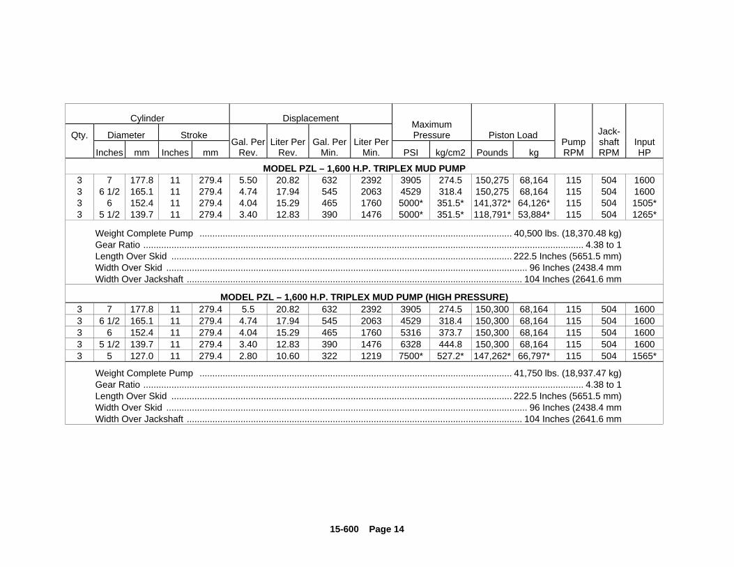
MODEL PZL – 1,600 H.P. TRIPLEX MUD PUMP3 7 177.8 11 279.4 5.50 20.82 632 2392 3905 274.5 150,275 68,164 115 504 16003 6 1/2 165.1 11 279.4 4.74 17.94 545 2063 4529 318.4 150,275 68,164 115 504 16003 6 152.4 11 279.4 4.04 15.29 465 1760 5000* 351.5* 141,372* 64,126* 115 504 1505*3 5 1/2 139.7 11 279.4 3.40 12.83 390 1476 5000* 351.5* 118,791* 53,884* 115 504 1265*
Weight Complete Pump .......................................................................................................................... 40,500 lbs. (18,370.48 kg)Gear Ratio ............................................................................................................................................................................ 4.38 to 1Length Over Skid ..................................................................................................................................... 222.5 Inches (5651.5 mm)Width Over Skid ............................................................................................................................................. 96 Inches (2438.4 mmWidth Over Jackshaft ................................................................................................................................... 104 Inches (2641.6 mm
MODEL PZL – 1,600 H.P. TRIPLEX MUD PUMP (HIGH PRESSURE)3 7 177.8 11 279.4 5.5 20.82 632 2392 3905 274.5 150,300 68,164 115 504 16003 6 1/2 165.1 11 279.4 4.74 17.94 545 2063 4529 318.4 150,300 68,164 115 504 16003 6 152.4 11 279.4 4.04 15.29 465 1760 5316 373.7 150,300 68,164 115 504 16003 5 1/2 139.7 11 279.4 3.40 12.83 390 1476 6328 444.8 150,300 68,164 115 504 16003 5 127.0 11 279.4 2.80 10.60 322 1219 7500* 527.2* 147,262* 66,797* 115 504 1565*
Weight Complete Pump .......................................................................................................................... 41,750 lbs. (18,937.47 kg)Gear Ratio ............................................................................................................................................................................ 4.38 to 1Length Over Skid ..................................................................................................................................... 222.5 Inches (5651.5 mm)Width Over Skid ............................................................................................................................................. 96 Inches (2438.4 mmWidth Over Jackshaft ................................................................................................................................... 104 Inches (2641.6 mm
15-600 Page 15
Cylinder Displacement
Qty. Diameter StrokeMaximumPressure Piston Load
Inches mm Inches mmGal. Per
Rev.Liter Per
Rev.Gal. Per
Min.Liter Per
Min. PSI kg/cm2 Pounds kgPumpRPM
Jack-shaftRPM
InputHP
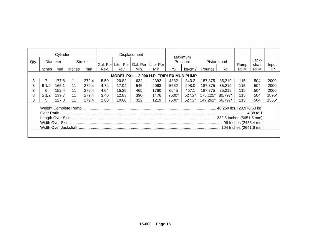
MODEL PXL – 2,000 H.P. TRIPLEX MUD PUMP3 7 177.8 11 279.4 5.50 20.82 632 2392 4882 343.2 187,875 85,219 115 504 20003 6 1/2 165.1 11 279.4 4.74 17.94 545 2063 5662 298.0 187,875 85,219 115 504 20003 6 152.4 11 279.4 4.04 15.29 465 1760 6645 467.1 187,875 85,219 115 504 20003 5 1/2 139.7 11 279.4 3.40 12.83 390 1476 7500* 527.2* 178,125* 80,797* 115 504 1895*3 5 127.0 11 279.4 2.80 10.60 322 1219 7500* 527.2* 147,262* 66,797* 115 504 1565*
Weight Complete Pump .......................................................................................................................... 46,250 lbs. (20,978.63 kg)Gear Ratio ............................................................................................................................................................................ 4.38 to 1Length Over Skid ..................................................................................................................................... 222.5 Inches (5651.5 mm)Width Over Skid ............................................................................................................................................. 96 Inches (2438.4 mmWidth Over Jackshaft ................................................................................................................................... 104 Inches (2641.6 mm
15-600 Page 16
SECTION 3ROUTINE MAINTENANCE & SERVICE INSTRUCTIONS
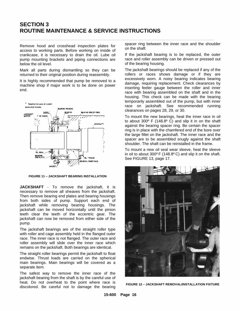
Remove hood and crosshead inspection plates foraccess to working parts. Before working on inside ofcrankcase, it is necessary to drain the oil. Lube oilpump mounting brackets and piping connections arebelow the oil level.Mark all parts during dismantling so they can bereturned to their original position during reassembly.It is highly recommended that pump be removed to amachine shop if major work is to be done on powerend.
FIGURE 11 – JACKSHAFT BEARING INSTALLATION
JACKSHAFT - To remove the jackshaft, it isnecessary to remove all sheaves from the jackshaft.Then remove bearing end plates and bearing housingsfrom both sides of pump. Support each end ofjackshaft while removing bearing housings. Thejackshaft can be moved horizontally until the pinionteeth clear the teeth of the eccentric gear. Thejackshaft can now be removed from either side of thepump.The jackshaft bearings are of the straight roller typewith roller and cage assembly held in the flanged outerrace. The inner race is not flanged. The outer race androller assembly will slide over the inner race whichremains on the jackshaft. Both bearings are identical.The straight roller bearings permit the jackshaft to floatendwise. Thrust loads are carried on the sphericalmain bearings. Main bearings will be covered as aseparate item.The safest way to remove the inner race of thejackshaft bearing from the shaft is by the careful use ofheat. Do not overheat to the point where race isdiscolored. Be careful not to damage the bearing
spacer ring between the inner race and the shoulderon the shaft.If the jackshaft bearing is to be replaced, the outerrace and roller assembly can be driven or pressed outof the bearing housing.The jackshaft bearings should be replaced if any of therollers or races shows damage or if they areexcessively worn. A noisy bearing indicates bearingdamage, requiring replacement. Check clearances byinserting feeler gauge between the roller and innerrace with bearing assembled on the shaft and in thehousing. This check can be made with the bearingtemporarily assembled out of the pump, but with innerrace on jackshaft. See recommended runningclearances on pages 28, 29, or 30.To mount the new bearings, heat the inner race in oilto about 300º F (148.8º C) and slip it in on the shaftagainst the bearing spacer ring. Be certain the spacerring is in place with the chamfered end of the bore overthe large fillet on the jackshaft. The inner race and thespacer are to be assembled snugly against the shaftshoulder. The shaft can be reinstalled in the frame.To mount a new oil seal wear sleeve, heat the sleevein oil to about 300º F (148.8º C) and slip it on the shaft.See FIGURE 13, page 17.
FIGURE 12 – JACKSHAFT REMOVAL/INSTALLATION FIXTURE
15-600 Page 17
PZGStroke:
7”
PZHStroke:
8”
PZJStroke:
9”
PZKStroke:
10”
PZLStroke:
11”
PXLStroke:
11”Dimensions Inches mm Inches mm Inches mm Inches mm Inches mm Inches mm
A 7.0 178 14.0 356 16.0 406 12.0 305 12.0 305 10.0 254B Diameter 7.0 178 7.75 197.0 8.335 211.71 10.75 273.0 10.75 273.0 11.5 292.1
C .38 9.6 .50 13.0 .50 13.0 1.75 44.5 1.75 44.5 1.00 25.4
D Diameter6.25 159.0
6.8786.880
174.70174.75
7.3787.680
187.40187.45
9.5049.505
241.40241.42
9.5049.505
241.40241.42
10.00710.005
254.17254.12
E ------ ------ 2.00 51 2.00 51 2.9 74 2.9 74 2.50 63.5
F Diameter 6.0046.006
152.50152.55
6.7526.754
171.50171.55
7.2527.254
184.20184.25
9.2529.254
235.00235.05
9.2529.254
235.00235.05
9.7559.753
247.77247.72
G ------ ------ 3.00 76.0 3.00 76.0 1.4 36 1.4 36 2.50 63.5H Diameter ------ ------ 6.88 175.0 7.38 187.5 10.0 254 10.0 254 10.2 259.08J Diameter 6.004
6.006152.50152.55
6.7526.754
171.50171.55
7.2527.254
184.20184.25
9.2529.254
235.00235.05
9.2529.254
235.00235.05
9.7559.753
247.77247.72
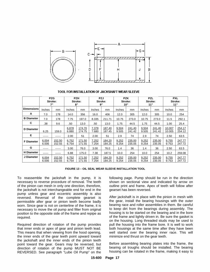
FIGURE 13 – OIL SEAL WEAR SLEEVE INSTALLATION TOOL
To reassemble the jackshaft in the pump, it isnecessary to reverse procedure of removal. The teethof the pinion can mesh in only one direction, therefore,the jackshaft is not interchangeable end for end in thepump unless gear and eccentric assembly is alsoreversed. Reversal of the complete gearset ispermissible after gear or pinion teeth become badlyworn. Since gear is not on centerline of the frame, it isnecessary to move the oil pump and filter from originalposition to the opposite side of the frame and repipe asrequired.
Required direction of rotation of the pump providesthat inner ends or apex of gear and pinion teeth lead.This means that when viewing from the hood opening,the inner ends of the gear teeth point upward towardthe jackshaft and the inner ends of the pinion teethpoint toward the gear. Gears may be reversed, butdirection of rotation of the pump MUST NOT BEREVERSED. See paragraph “Lube Oil Pump” on the
following page. Pump should be run in the directionshown on sectional view and indicated by arrow onoutline print and frame. Apex of teeth will follow aftergearset has been reversed.
After jackshaft is in place with the pinion in mesh withthe gear, install the bearing housings with the outerbearing race and roller assemblies in them. Be carefulto keep dirt from the bearings during assembly. Thehousing is to be started on the bearing and in the boreof the frame and lightly driven in. Be sure the gasket ison the housing. Long threaded studs may be used topull the housing into the frame bore. It is well to workboth housings at the same time after they have beenwell started over the bearing inner race. This willminimize end thrust on the gear teeth.
Before assembling bearing plates into the frame, thebearing oil troughs should be installed. The bearinghousing can be rotated in the frame, making it easy to
15-600 Page 18
level oil trough properly. Top of oil trough is to be level.The PZG pump does not have oil trough.Outer oil seals are to be placed in the bearing endplate after it is bolted to the bearing housing andframe. Coat inside of oil seal liberally with bearinggrease. The seal is to be installed with garter spring toinside, toward bearing. Permanently bolt jackshaftbearing housings and their end plates to the frame.
LUBE OIL PUMP – The lube oil pump, part number46C21, used in the PZG, PZH and PZJ pumps can bereversed in direction when the complete gear sets arereversed after the following procedure is completed.Remove the oil pump with standard left hand helixdrive gear from the pump frame. Remove the drivegear from the oil pump shaft.
Remove the end cap from the oil pump opposite theshaft end, remove the drain plug screw opposite the oilpump discharge port. Install the drain plug screw in thehole provided 180o or opposite from the suction port.Reverse the suction and discharge lines to the lube oilpump and reverse the data tag “IN – ROTATION –OUT”. The drain plug screw must be installed in thepump body opposite the oil pump discharge port.Replace the end cap.
Install the optional right hand helix drive gear on the oilpump shaft. Install the oil pump and gear assembly onalternate mounting pad in the pump sump to mesh withreversed eccentric gear.
The lube oil pump, part numbers 46C58 (previousproduction) and 201PAH188 (current production), usedin the PZK, PZL & PXL pumps can be reversed indirection without modification to the pump. The oil flowthrough the pump will reverse direction when shaft isrotated in reverse.
Viewing the oil pump 46C58 from the shaft end,rotating the shaft clockwise, the right hand pumpopening is the inlet. When rotating shaftcounterclockwise, the left hand opening is the inlet andthe right hand opening becomes the outlet.
When shaft rotation of the 201PAH188 oil pumpchanges direction, the direction of flow changeswithout changing inlet and outlet port positions.
When reversing the complete gear sets on PZK, PZLand PXL pumps, the left hand helix pump drive gearmust be replaced with an optional right hand helixdrive gear. Install the oil pump and drive gearassembly on the alternate sump mounting pad to meshwith the reversed eccentric gear.
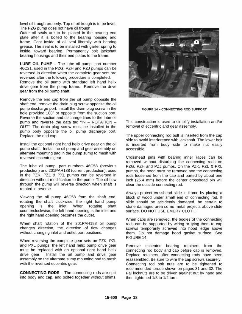
CONNECTING RODS – The connecting rods are splitinto body and cap, and bolted together without shims.y.
FIGURE 14 – CONNECTING ROD SUPPORT
This construction is used to simplify installation and/orremoval of eccentric and gear assembly.
The upper connecting rod bolt is inserted from the capside to avoid interference with jackshaft. The lower boltis inserted from body side to make nut easilyaccessible.
Crosshead pins with bearing inner races can beremoved without disturbing the connecting rods onPZG, PZH and PZJ pumps. On the PZK, PZL & PXLpumps, the hood must be removed and the connectingrods loosened from the cap and parted by about oneinch (25.4 mm) before the center crosshead pin willclear the outside connecting rod.
Always protect crosshead slide in frame by placing ablock of wood under small end of connecting rod. Ifslide should be accidently damaged, be certain tostone damaged area so no metal projects above slidesurface. DO NOT USE EMERY CLOTH.
When caps are removed, the bodies of the connectingrods can be supported by wiring or tying them to capscrews temporarily screwed into hood ledge abovethem. Do not damage hood gasket surface. SeeFIGURE 14.
Remove eccentric bearing retainers from theconnecting rod body and cap before cap is removed.Replace retainers after connecting rods have beenreassembled. Be sure to wire the cap screws securely.Connecting rod bolt nuts are to be tightened torecommended torque shown on pages 31 and 32. ThePal locknuts are to be driven against nut by hand andthen tightened 1/3 to 1/2 turn.
15-600 Page 19
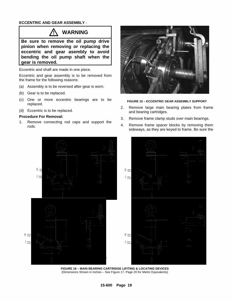
ECCENTRIC AND GEAR ASSEMBLY -
WARNINGBe sure to remove the oil pump drivepinion when removing or replacing theeccentric and gear asembly to avoidbending the oil pump shaft when thegear is removed.
Eccentric and shaft are made in one piece.Eccentric and gear assembly is to be removed fromthe frame for the following reasons:
(a) Assembly is to be reversed after gear is worn.
(b) Gear is to be replaced.
(c) One or more eccentric bearings are to bereplaced.
(d) Eccentric is to be replaced.Procedure For Removal:1. Remove connecting rod caps and support the
rods.
FIGURE 15 – ECCENTRIC GEAR ASSEMBLY SUPPORT
2. Remove large main bearing plates from frameand bearing cartridges.
3. Remove frame clamp studs over main bearings.
4. Remove frame spacer blocks by removing themsideways, as they are keyed to frame. Be sure the
2532
2532
DRILL THRU ONE HOLE
2932
DRILL THRU ONE HOLE
2532
DRILL THRU ONE HOLE
78 DRILL THRU
2 HOLES
78 DRILL THRU
2 HOLES1"2 DRILL THRU
2 HOLES
78 DRILL THRU
2 HOLES
1.5
3.0
4.5
1.75
.69 R2.22
4.44
7.9 R
45
1.0
.4
4.2
5.5
WELD
1.0
1" - 8 UNC THREADFOR EYEBOLT
DRILL THRU ONE HOLE
C75427FOR PZG ONLY
1" - 8 UNC THREADFOR EYEBOLT
1.0
WELD
1.0
4.56
6.0
.387.0
2.12
.68 R
8.86 R
4.88
2.44
4.0
2.0
45
C74625FOR PZH ONLY
C74911FOR PZK, PZL & PXL ONLY
45
1.0
WELD
1.0
2.0
4.0
8.0
2.28
.88 R
6.40
11.5 R
3.20
5.5
7.0
- 7 UNC THREAD FOR EYEBOLT
1 18
- 7 UNC THREAD FOR EYEBOLT
18
2
4
45
8
1
1
WELD
2 3
4
1
25
7
8
R
3
8
1
85
6 1
2
1"
3
162
27
32
R9 C73507FOR PZJ ONLY
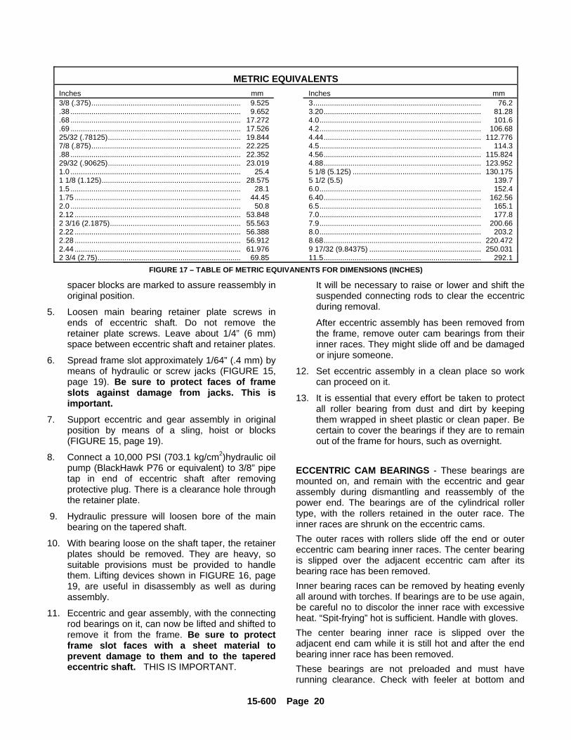
FIGURE 16 – MAIN BEARING CARTRIDGE LIFITING & LOCATING DEVICES(Dimensions Shown in Inches – See Figure 17, Page 20 for Metric Equivalents)
15-600 Page 20
METRIC EQUIVALENTSInches mm Inches mm3/8 (.375)........................................................................ 9.525 3................................................................................. 76.2.38 .................................................................................. 9.652 3.20............................................................................ 81.28.68 .................................................................................. 17.272 4.0.............................................................................. 101.6.69 .................................................................................. 17.526 4.2.............................................................................. 106.6825/32 (.78125)................................................................ 19.844 4.44............................................................................ 112.7767/8 (.875)........................................................................ 22.225 4.5.............................................................................. 114.3.88 .................................................................................. 22.352 4.56............................................................................ 115.82429/32 (.90625)................................................................ 23.019 4.88............................................................................ 123.9521.0 .................................................................................. 25.4 5 1/8 (5.125) .............................................................. 130.1751 1/8 (1.125)................................................................... 28.575 5 1/2 (5.5) 139.71.5 .................................................................................. 28.1 6.0.............................................................................. 152.41.75 ................................................................................ 44.45 6.40............................................................................ 162.562.0 .................................................................................. 50.8 6.5.............................................................................. 165.12.12 ................................................................................ 53.848 7.0.............................................................................. 177.82 3/16 (2.1875)............................................................... 55.563 7.9.............................................................................. 200.662.22 ................................................................................ 56.388 8.0.............................................................................. 203.22.28 ................................................................................ 56.912 8.68............................................................................ 220.4722.44 ................................................................................ 61.976 9 17/32 (9.84375) ...................................................... 250.0312 3/4 (2.75)..................................................................... 69.85 11.5............................................................................ 292.1
FIGURE 17 – TABLE OF METRIC EQUIVANENTS FOR DIMENSIONS (INCHES)
spacer blocks are marked to assure reassembly inoriginal position.
5. Loosen main bearing retainer plate screws inends of eccentric shaft. Do not remove theretainer plate screws. Leave about 1/4” (6 mm)space between eccentric shaft and retainer plates.
6. Spread frame slot approximately 1/64” (.4 mm) bymeans of hydraulic or screw jacks (FIGURE 15,page 19). Be sure to protect faces of frameslots against damage from jacks. This isimportant.
7. Support eccentric and gear assembly in originalposition by means of a sling, hoist or blocks(FIGURE 15, page 19).
8. Connect a 10,000 PSI (703.1 kg/cm2)hydraulic oilpump (BlackHawk P76 or equivalent) to 3/8” pipetap in end of eccentric shaft after removingprotective plug. There is a clearance hole throughthe retainer plate.
9. Hydraulic pressure will loosen bore of the mainbearing on the tapered shaft.
10. With bearing loose on the shaft taper, the retainerplates should be removed. They are heavy, sosuitable provisions must be provided to handlethem. Lifting devices shown in FIGURE 16, page19, are useful in disassembly as well as duringassembly.
11. Eccentric and gear assembly, with the connectingrod bearings on it, can now be lifted and shifted toremove it from the frame. Be sure to protectframe slot faces with a sheet material toprevent damage to them and to the taperedeccentric shaft. THIS IS IMPORTANT.
It will be necessary to raise or lower and shift thesuspended connecting rods to clear the eccentricduring removal.
After eccentric assembly has been removed fromthe frame, remove outer cam bearings from theirinner races. They might slide off and be damagedor injure someone.
12. Set eccentric assembly in a clean place so workcan proceed on it.
13. It is essential that every effort be taken to protectall roller bearing from dust and dirt by keepingthem wrapped in sheet plastic or clean paper. Becertain to cover the bearings if they are to remainout of the frame for hours, such as overnight.
ECCENTRIC CAM BEARINGS - These bearings aremounted on, and remain with the eccentric and gearassembly during dismantling and reassembly of thepower end. The bearings are of the cylindrical rollertype, with the rollers retained in the outer race. Theinner races are shrunk on the eccentric cams.The outer races with rollers slide off the end or outereccentric cam bearing inner races. The center bearingis slipped over the adjacent eccentric cam after itsbearing race has been removed.Inner bearing races can be removed by heating evenlyall around with torches. If bearings are to be use again,be careful no to discolor the inner race with excessiveheat. “Spit-frying” hot is sufficient. Handle with gloves.The center bearing inner race is slipped over theadjacent end cam while it is still hot and after the endbearing inner race has been removed.These bearings are not preloaded and must haverunning clearance. Check with feeler at bottom and
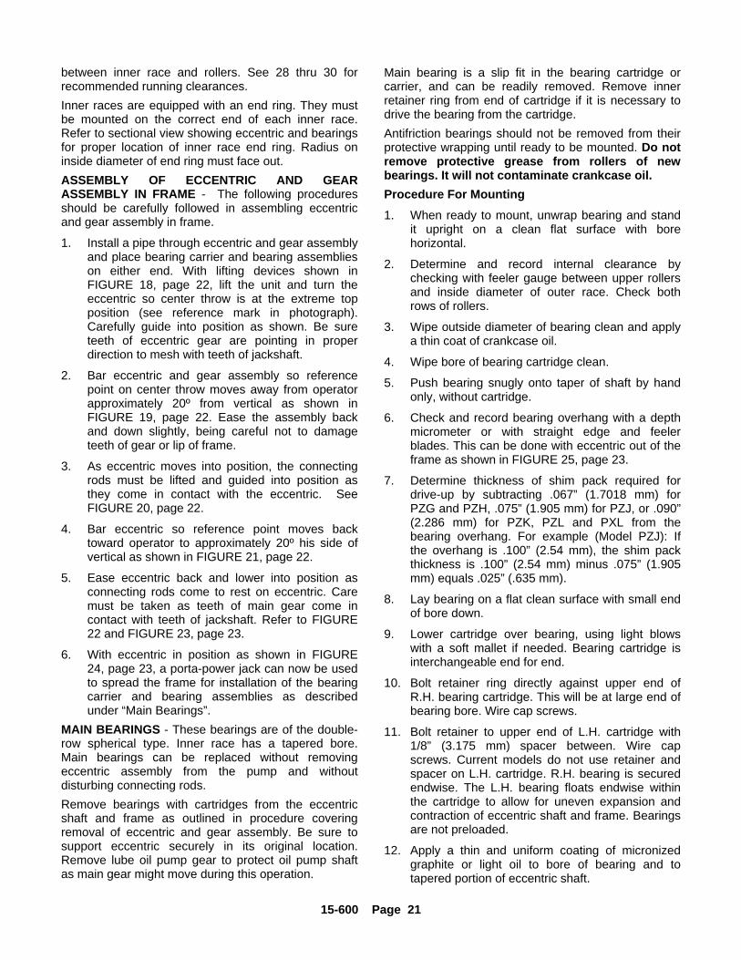
15-600 Page 21
between inner race and rollers. See 28 thru 30 forrecommended running clearances.Inner races are equipped with an end ring. They mustbe mounted on the correct end of each inner race.Refer to sectional view showing eccentric and bearingsfor proper location of inner race end ring. Radius oninside diameter of end ring must face out.ASSEMBLY OF ECCENTRIC AND GEARASSEMBLY IN FRAME - The following proceduresshould be carefully followed in assembling eccentricand gear assembly in frame.
1. Install a pipe through eccentric and gear assemblyand place bearing carrier and bearing assemblieson either end. With lifting devices shown inFIGURE 18, page 22, lift the unit and turn theeccentric so center throw is at the extreme topposition (see reference mark in photograph).Carefully guide into position as shown. Be sureteeth of eccentric gear are pointing in properdirection to mesh with teeth of jackshaft.
2. Bar eccentric and gear assembly so referencepoint on center throw moves away from operatorapproximately 20º from vertical as shown inFIGURE 19, page 22. Ease the assembly backand down slightly, being careful not to damageteeth of gear or lip of frame.
3. As eccentric moves into position, the connectingrods must be lifted and guided into position asthey come in contact with the eccentric. SeeFIGURE 20, page 22.
4. Bar eccentric so reference point moves backtoward operator to approximately 20º his side ofvertical as shown in FIGURE 21, page 22.
5. Ease eccentric back and lower into position asconnecting rods come to rest on eccentric. Caremust be taken as teeth of main gear come incontact with teeth of jackshaft. Refer to FIGURE22 and FIGURE 23, page 23.
6. With eccentric in position as shown in FIGURE24, page 23, a porta-power jack can now be usedto spread the frame for installation of the bearingcarrier and bearing assemblies as describedunder “Main Bearings”.
MAIN BEARINGS - These bearings are of the double-row spherical type. Inner race has a tapered bore.Main bearings can be replaced without removingeccentric assembly from the pump and withoutdisturbing connecting rods.Remove bearings with cartridges from the eccentricshaft and frame as outlined in procedure coveringremoval of eccentric and gear assembly. Be sure tosupport eccentric securely in its original location.Remove lube oil pump gear to protect oil pump shaftas main gear might move during this operation.
Main bearing is a slip fit in the bearing cartridge orcarrier, and can be readily removed. Remove innerretainer ring from end of cartridge if it is necessary todrive the bearing from the cartridge.Antifriction bearings should not be removed from theirprotective wrapping until ready to be mounted. Do notremove protective grease from rollers of newbearings. It will not contaminate crankcase oil.Procedure For Mounting1. When ready to mount, unwrap bearing and stand
it upright on a clean flat surface with borehorizontal.
2. Determine and record internal clearance bychecking with feeler gauge between upper rollersand inside diameter of outer race. Check bothrows of rollers.
3. Wipe outside diameter of bearing clean and applya thin coat of crankcase oil.
4. Wipe bore of bearing cartridge clean.
5. Push bearing snugly onto taper of shaft by handonly, without cartridge.
6. Check and record bearing overhang with a depthmicrometer or with straight edge and feelerblades. This can be done with eccentric out of theframe as shown in FIGURE 25, page 23.
7. Determine thickness of shim pack required fordrive-up by subtracting .067” (1.7018 mm) forPZG and PZH, .075” (1.905 mm) for PZJ, or .090”(2.286 mm) for PZK, PZL and PXL from thebearing overhang. For example (Model PZJ): Ifthe overhang is .100” (2.54 mm), the shim packthickness is .100” (2.54 mm) minus .075” (1.905mm) equals .025” (.635 mm).
8. Lay bearing on a flat clean surface with small endof bore down.
9. Lower cartridge over bearing, using light blowswith a soft mallet if needed. Bearing cartridge isinterchangeable end for end.
10. Bolt retainer ring directly against upper end ofR.H. bearing cartridge. This will be at large end ofbearing bore. Wire cap screws.
11. Bolt retainer to upper end of L.H. cartridge with1/8” (3.175 mm) spacer between. Wire capscrews. Current models do not use retainer andspacer on L.H. cartridge. R.H. bearing is securedendwise. The L.H. bearing floats endwise withinthe cartridge to allow for uneven expansion andcontraction of eccentric shaft and frame. Bearingsare not preloaded.
12. Apply a thin and uniform coating of micronizedgraphite or light oil to bore of bearing and totapered portion of eccentric shaft.
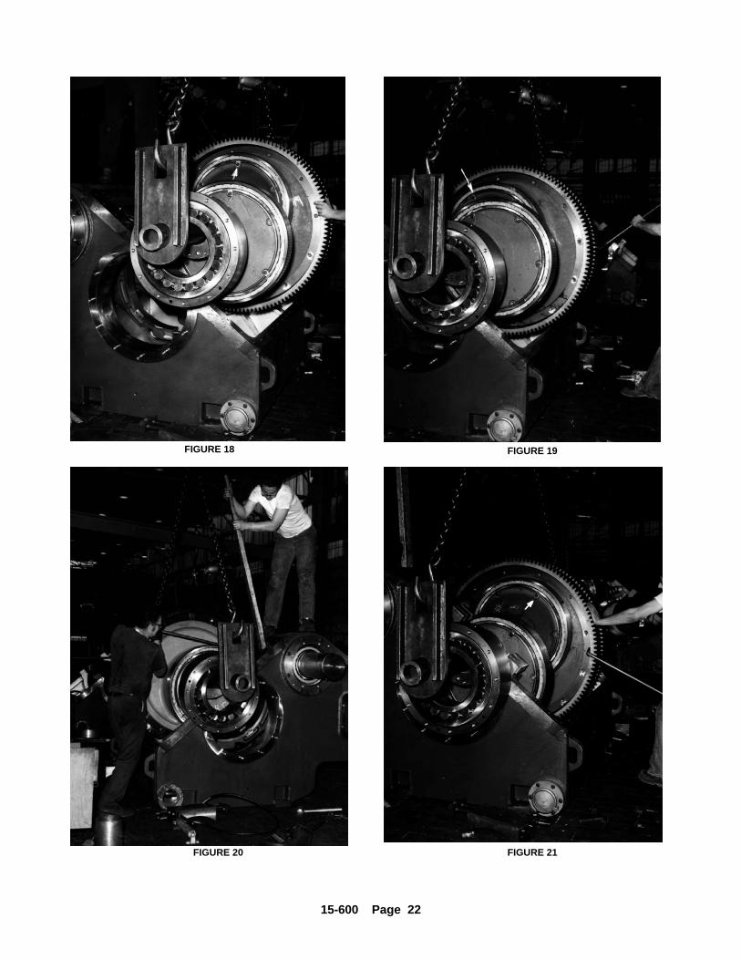
15-600 Page 22
FIGURE 18 FIGURE 19
FIGURE 20 FIGURE 21
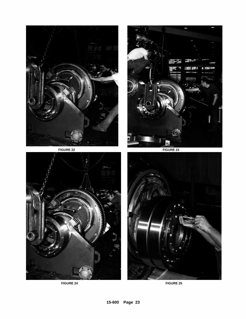
15-600 Page 23
FIGURE 22 FIGURE 23
FIGURE 24 FIGURE 25
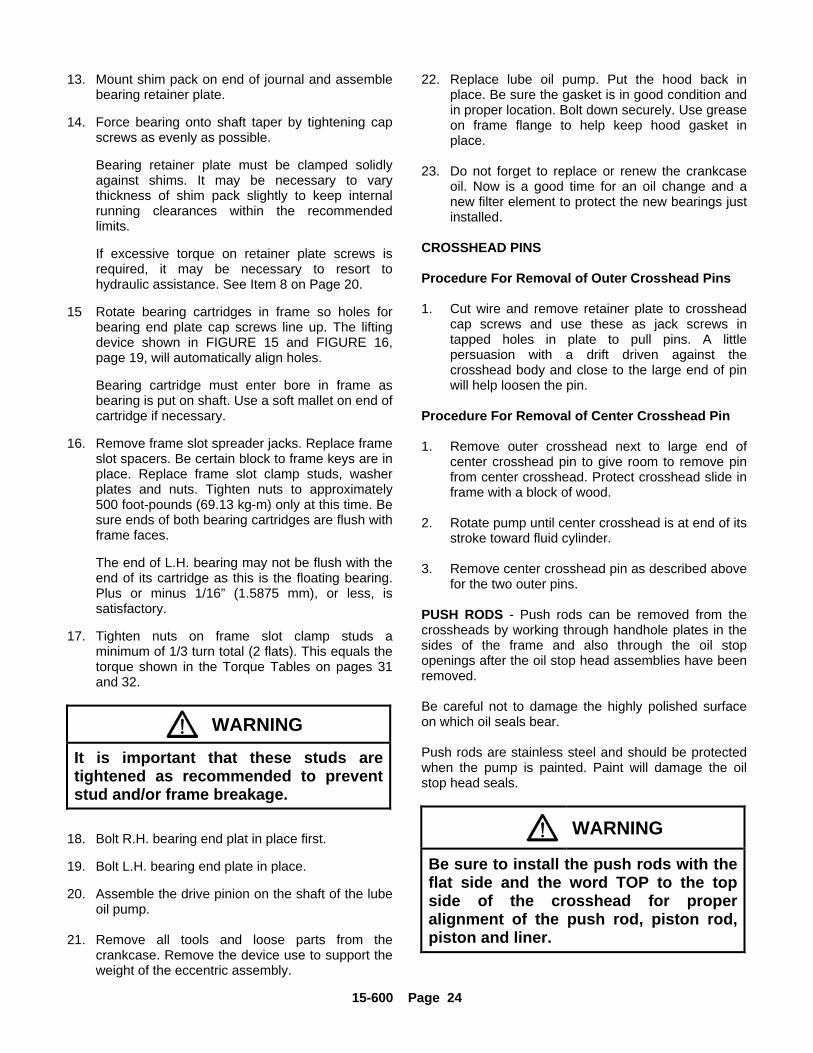
15-600 Page 24
13. Mount shim pack on end of journal and assemblebearing retainer plate.
14. Force bearing onto shaft taper by tightening capscrews as evenly as possible.
Bearing retainer plate must be clamped solidlyagainst shims. It may be necessary to varythickness of shim pack slightly to keep internalrunning clearances within the recommendedlimits.
If excessive torque on retainer plate screws isrequired, it may be necessary to resort tohydraulic assistance. See Item 8 on Page 20.
15 Rotate bearing cartridges in frame so holes forbearing end plate cap screws line up. The liftingdevice shown in FIGURE 15 and FIGURE 16,page 19, will automatically align holes.
Bearing cartridge must enter bore in frame asbearing is put on shaft. Use a soft mallet on end ofcartridge if necessary.
16. Remove frame slot spreader jacks. Replace frameslot spacers. Be certain block to frame keys are inplace. Replace frame slot clamp studs, washerplates and nuts. Tighten nuts to approximately500 foot-pounds (69.13 kg-m) only at this time. Besure ends of both bearing cartridges are flush withframe faces.
The end of L.H. bearing may not be flush with theend of its cartridge as this is the floating bearing.Plus or minus 1/16” (1.5875 mm), or less, issatisfactory.
17. Tighten nuts on frame slot clamp studs aminimum of 1/3 turn total (2 flats). This equals thetorque shown in the Torque Tables on pages 31and 32.
WARNINGIt is important that these studs aretightened as recommended to preventstud and/or frame breakage.
18. Bolt R.H. bearing end plat in place first.
19. Bolt L.H. bearing end plate in place.
20. Assemble the drive pinion on the shaft of the lubeoil pump.
21. Remove all tools and loose parts from thecrankcase. Remove the device use to support theweight of the eccentric assembly.
22. Replace lube oil pump. Put the hood back inplace. Be sure the gasket is in good condition andin proper location. Bolt down securely. Use greaseon frame flange to help keep hood gasket inplace.
23. Do not forget to replace or renew the crankcaseoil. Now is a good time for an oil change and anew filter element to protect the new bearings justinstalled.
CROSSHEAD PINS
Procedure For Removal of Outer Crosshead Pins
1. Cut wire and remove retainer plate to crossheadcap screws and use these as jack screws intapped holes in plate to pull pins. A littlepersuasion with a drift driven against thecrosshead body and close to the large end of pinwill help loosen the pin.
Procedure For Removal of Center Crosshead Pin
1. Remove outer crosshead next to large end ofcenter crosshead pin to give room to remove pinfrom center crosshead. Protect crosshead slide inframe with a block of wood.
2. Rotate pump until center crosshead is at end of itsstroke toward fluid cylinder.
3. Remove center crosshead pin as described abovefor the two outer pins.
PUSH RODS - Push rods can be removed from thecrossheads by working through handhole plates in thesides of the frame and also through the oil stopopenings after the oil stop head assemblies have beenremoved.
Be careful not to damage the highly polished surfaceon which oil seals bear.
Push rods are stainless steel and should be protectedwhen the pump is painted. Paint will damage the oilstop head seals.
WARNING
Be sure to install the push rods with theflat side and the word TOP to the topside of the crosshead for properalignment of the push rod, piston rod,piston and liner.
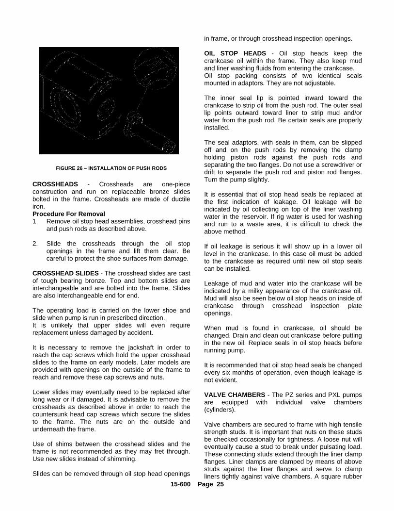
15-600 Page 25
B76904
FIGURE 26 – INSTALLATION OF PUSH RODS
CROSSHEADS - Crossheads are one-piececonstruction and run on replaceable bronze slidesbolted in the frame. Crossheads are made of ductileiron.Procedure For Removal1. Remove oil stop head assemblies, crosshead pins
and push rods as described above.
2. Slide the crossheads through the oil stopopenings in the frame and lift them clear. Becareful to protect the shoe surfaces from damage.
CROSSHEAD SLIDES - The crosshead slides are castof tough bearing bronze. Top and bottom slides areinterchangeable and are bolted into the frame. Slidesare also interchangeable end for end.
The operating load is carried on the lower shoe andslide when pump is run in prescribed direction.It is unlikely that upper slides will even requirereplacement unless damaged by accident.
It is necessary to remove the jackshaft in order toreach the cap screws which hold the upper crossheadslides to the frame on early models. Later models areprovided with openings on the outside of the frame toreach and remove these cap screws and nuts.
Lower slides may eventually need to be replaced afterlong wear or if damaged. It is advisable to remove thecrossheads as described above in order to reach thecountersunk head cap screws which secure the slidesto the frame. The nuts are on the outside andunderneath the frame.
Use of shims between the crosshead slides and theframe is not recommended as they may fret through.Use new slides instead of shimming.
Slides can be removed through oil stop head openings
in frame, or through crosshead inspection openings.
OIL STOP HEADS - Oil stop heads keep thecrankcase oil within the frame. They also keep mudand liner washing fluids from entering the crankcase.Oil stop packing consists of two identical sealsmounted in adaptors. They are not adjustable.
The inner seal lip is pointed inward toward thecrankcase to strip oil from the push rod. The outer seallip points outward toward liner to strip mud and/orwater from the push rod. Be certain seals are properlyinstalled.
The seal adaptors, with seals in them, can be slippedoff and on the push rods by removing the clampholding piston rods against the push rods andseparating the two flanges. Do not use a screwdriver ordrift to separate the push rod and piston rod flanges.Turn the pump slightly.
It is essential that oil stop head seals be replaced atthe first indication of leakage. Oil leakage will beindicated by oil collecting on top of the liner washingwater in the reservoir. If rig water is used for washingand run to a waste area, it is difficult to check theabove method.
If oil leakage is serious it will show up in a lower oillevel in the crankcase. In this case oil must be addedto the crankcase as required until new oil stop sealscan be installed.
Leakage of mud and water into the crankcase will beindicated by a milky appearance of the crankcase oil.Mud will also be seen below oil stop heads on inside ofcrankcase through crosshead inspection plateopenings.
When mud is found in crankcase, oil should bechanged. Drain and clean out crankcase before puttingin the new oil. Replace seals in oil stop heads beforerunning pump.
It is recommended that oil stop head seals be changedevery six months of operation, even though leakage isnot evident.
VALVE CHAMBERS - The PZ series and PXL pumpsare equipped with individual valve chambers(cylinders).
Valve chambers are secured to frame with high tensilestrength studs. It is important that nuts on these studsbe checked occasionally for tightness. A loose nut willeventually cause a stud to break under pulsating load.These connecting studs extend through the liner clampflanges. Liner clamps are clamped by means of abovestuds against the liner flanges and serve to clampliners tightly against valve chambers. A square rubber
15-600 Page 26
compound gasket seals end of liner against valvechamber. When replacing a valve chamber it isnecessary to remove the discharge manifold. Alsoremove screws holding suction manifold to thechamber being replaced. Loosen, but do not removesuction manifold screws in the other two chambers.Suction manifold can be dropped enough to cleargaskets. These members are to be securely bolted tothe new valve chamber before it is finally tightenedagainst frame connecting flange. Be sure manifoldgaskets are in place.
LINER CLAMP AND LINERS - When liner clamps arereinstalled or replaced, it is advisable to check cylinderto frame stud nuts and tighten if necessary. Refer topages 31 and 32 for proper torques.
Nuts holding liner clamps in place should not beovertightened as distortion of the clamp and liner boremay result. Recommended torque values are shownon pages 31 and 32.
Change size of pistons and liners as volume and/orpressure requirements change. See rating charts onpages 12 thru 15.
Liners are replaced by removing the liner clamp. Linersshould be cleaned and oiled after removal to protectagainst rusting during storage, so they can be usedagain.
Pump liners are to be clean both inside and out wheninstalled. Also clean the liner clamp bore and lightly oilall surfaces.
Use new gaskets when installing liners and be sure toclean all surfaces against which the gaskets fit. Linersor valve chambers may be cut by leaking gaskets.
PISTONS - Single-acting pistons consist of a steelpiston body with insert retained by a washer and snapring.
Pistons, with piston rods, can be removed or installedthrough suction valve opening after valve upper guideis removed by turning it 90_. Valve spring must also beremoved. 7” pistons on PZG, PZH and PZJ pumpsmust be removed through frame. In the 7500 PSI highpressure fluid cylinders, 6” diameter is the maximumthat can be removed through the suction valveopening. Larger diameters must be removed throughthe frame.
It is recommended that a piston and rod assembly bekept ready for replacement. This is a practical time-saver.
PISTON ROD - Piston rods are manufactured of highcarbon steel. They are electrolytically plated to protectagainst corrosion. They are provided with a knurled
section so rod can be held while tightening piston nut.It is important that piston rod nut be tightened torecommended torque shown on pages 31 and 32.
Piston rod to piston fit is straight. Piston fits againstflange on piston rod with on “O” ring gasket to prevent lconnecting flanges and pilots. DO NOT use ascrewdriver or cold chisel to separate the flanges - turnthe pump slightly.
For pumps with threaded piston rod to push rodconnection, tighten to torque specified on pages 31and 32.
PISTON WASHING SYSTEM - The piston washingsystem is vital to the satisfactory performance and lifeof pistons and liners. The complete system must bekept in good operating condition. Washing fluid shouldbe maintained in good condition and should bereplaced when contaminated to the point where freecirculation is impaired. This is of utmost importanceand should be impressed upon all operators of thepump.
Water supply lines should be permanently attached tothe openings provided in the circulating pump and thetank. Water is then quickly available as a washing fluidor to flush out the lines by operating the proper valvesin the piping system.
The piston washing fluid may be varied according toconditions and operator’s preference. Water makes asuitable washing fluid under most conditions. Goodresults can be obtained using water with one-halfgallon (1.9 liters) of soluble oil per tank of water withinthe closed system. A light oil gives good results undersome conditions, and can be used under severefreezing conditions.
The more fluid circulated, the better; however, it shouldbe regulated by a valve in discharge line of thecentrifugal circulating pump to prevent splashing andbeing blown about.
MAINTENANCE OF VALVES - In order to keep thepump in its best operating condition, it is necessary toexamine the suction and discharge valves occasionallyto see that excessive wear or cutting by the slush ormud has not impaired their efficiency. Any worn ordamaged parts should be replaced.
This is especially true with regard to the inserts.Standard inserts are made from urethane and are thepart of the valve which should be changed mostfrequently. They are much cheaper than the valves andseats, and if the inserts are renewed as soon as theybegin to fail, the more expensive steel parts will lastmuch longer. Routine inspection of valves every two orthree days is recommended.
15-600 Page 27
When removing a worn valve seat, use the Gardner-Denver puller powered with a hydraulic jack. Be carefulto chain or tie the jack down as it will jump violentlywhen the valve seat lets go. If it becomes necessary toresort to the use of heat or a cutting torch to remove avalve seat, the services of a man experienced in theseoperations is necessary.
Before putting new seats in the pump, the tapered borein the valve seat deck of the cylinder must bethoroughly cleaned with a wire brush. Wire brushshould be used around the bore rather than up anddown. Wipe the bore clean and do not use oil orgrease. The bore must be clean and dry or seat maynot seat properly. The valve seat tapered surface mustbe cleaned and dry before assembling in cylinder deck.
Place the new seat in the bore. Use an old valvebumper or a block of hard wood and drive with asledge to a snug initial fit. The pressure load on thevalve in operation will drive the seat home. Neverreuse an old seat once it has been removed from acylinder, as it may not fit solidly in the valve deck.
Replace the valve guide or valve guide bushings ifworn. Replace the valve spring if it is worn, corroded,distorted, or below normal tension. Valves are providedwith stainless steel springs for maximum operating life.A broken spring will cause rapid wear of valve guidesand should be replaced. It will also cause wear onsuction valve guide mounting lugs inside the valvechamber (cylinder).
Do not put a used valve assembly on a new seatunless it is in practically a new condition. Be sure toreplace a doubtful insert to protect seat and bumper.
It requires experience and judgment to determine ifvalve parts should be replaced or not. Valves arecheaper than downtime.
When installing valves, wipe all sealing surfaces clean,put the gasket carefully in place in the valve chamberand install cover plate. Be sure gasket is not twisted orextruded. Tighten valve cover lock securely by using abar and hammer.
The life of the valves will be lengthened if the mudtanks are kept clean. In may cases foreign objects arecaught under the valves, thereby holding them openand causing rapid cutting of the seats and valves.
SUCTION STRAINER - A suction strainer isrecommended for the suction line of every pump toprotect the valves.The current PZ series and PXL pumps are notequipped with a suction strainer. A commercialstrainer, however, may be installed in the suction lineahead of the pump.
The early PZJ pumps were equipped with a perforatedmetal strainer inside the suction manifold. This strainercan be removed from the end opposite the suction linefor inspection and cleaning. Strainer should bechecked if the pump starts to run rough, with violentdischarge pulsations. One or more cylinders may havetheir suction obstructed by debris in the strainer.
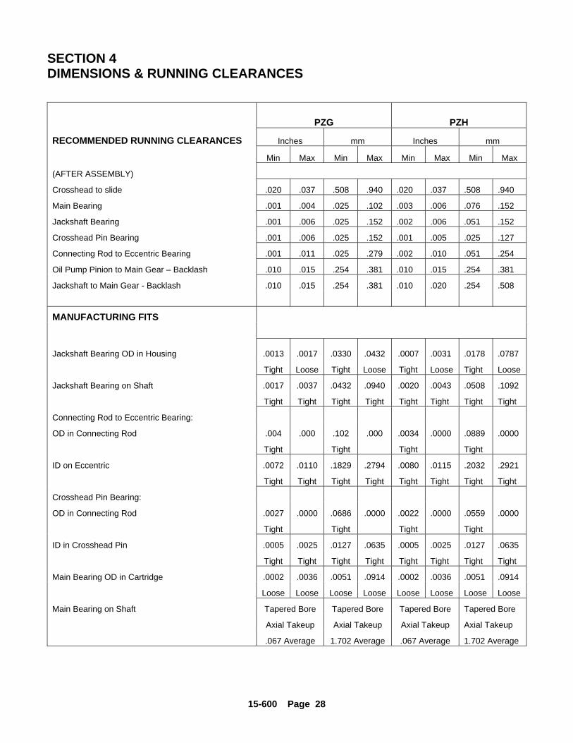
15-600 Page 28
SECTION 4DIMENSIONS & RUNNING CLEARANCES
PZG PZH
RECOMMENDED RUNNING CLEARANCES Inches mm Inches mm
Min Max Min Max Min Max Min Max
(AFTER ASSEMBLY)
Crosshead to slide .020 .037 .508 .940 .020 .037 .508 .940
Main Bearing .001 .004 .025 .102 .003 .006 .076 .152
Jackshaft Bearing .001 .006 .025 .152 .002 .006 .051 .152
Crosshead Pin Bearing .001 .006 .025 .152 .001 .005 .025 .127
Connecting Rod to Eccentric Bearing .001 .011 .025 .279 .002 .010 .051 .254
Oil Pump Pinion to Main Gear – Backlash .010 .015 .254 .381 .010 .015 .254 .381
Jackshaft to Main Gear - Backlash .010 .015 .254 .381 .010 .020 .254 .508
MANUFACTURING FITS
Jackshaft Bearing OD in Housing .0013 .0017 .0330 .0432 .0007 .0031 .0178 .0787
Tight Loose Tight Loose Tight Loose Tight Loose
Jackshaft Bearing on Shaft .0017 .0037 .0432 .0940 .0020 .0043 .0508 .1092
Tight Tight Tight Tight Tight Tight Tight Tight
Connecting Rod to Eccentric Bearing:
OD in Connecting Rod .004 .000 .102 .000 .0034 .0000 .0889 .0000
Tight Tight Tight Tight
ID on Eccentric .0072 .0110 .1829 .2794 .0080 .0115 .2032 .2921
Tight Tight Tight Tight Tight Tight Tight Tight
Crosshead Pin Bearing:
OD in Connecting Rod .0027 .0000 .0686 .0000 .0022 .0000 .0559 .0000
Tight Tight Tight Tight
ID in Crosshead Pin .0005 .0025 .0127 .0635 .0005 .0025 .0127 .0635
Tight Tight Tight Tight Tight Tight Tight Tight
Main Bearing OD in Cartridge .0002 .0036 .0051 .0914 .0002 .0036 .0051 .0914
Loose Loose Loose Loose Loose Loose Loose Loose
Main Bearing on Shaft Tapered Bore Tapered Bore Tapered Bore Tapered Bore
Axial Takeup Axial Takeup Axial Takeup Axial Takeup
.067 Average 1.702 Average .067 Average 1.702 Average
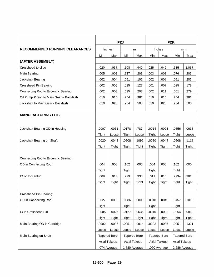
15-600 Page 29
PZJ PZK
RECOMMENDED RUNNING CLEARANCES Inches mm Inches mm
Min Max Min Max Min Max Min Max
(AFTER ASSEMBLY)Crosshead to slide .020 .037 .508 .940 .025 .042 .635 1.067
Main Bearing .005 .008 .127 .203 .003 .008 .076 .203
Jackshaft Bearing .002 .004 .051 .102 .002 .008 .051 .203
Crosshead Pin Bearing .002 .005 .025 .127 .001 .007 .025 .178
Connecting Rod to Eccentric Bearing .002 .008 .025 .203 .002 .011 .051 .279
Oil Pump Pinion to Main Gear – Backlash .010 .015 .254 .381 .010 .015 .254 .381
Jackshaft to Main Gear - Backlash .010 .020 .254 .508 .010 .020 .254 .508
MANUFACTURING FITS
Jackshaft Bearing OD in Housing .0007 .0031 .0178 .787 .0014 .0025 .0356 .0635
Tight Loose Tight Loose Tight Loose Tight Loose
Jackshaft Bearing on Shaft .0020 .0043 .0508 .1092 .0020 .0044 .0508 .1118
Tight Tight Tight Tight Tight Tight Tight Tight
Connecting Rod to Eccentric Bearing:
OD in Connecting Rod .004 .000 .102 .000 .004 .000 .102 .000
Tight Tight Tight Tight
ID on Eccentric .009 .013 .229 .330 .011 .015 .2794 .381
Tight Tight Tight Tight Tight Tight Tight Tight
Crosshead Pin Bearing:
OD in Connecting Rod .0027 .0000 .0686 .0000 .0018 .0040 .0457 .1016
Tight Tight Tight Tight
ID in Crosshead Pin .0005 .0025 .0127 .0635 .0010 .0032 .0254 .0813
Tight Tight Tight Tight Tight Tight Tight Tight
Main Bearing OD in Cartridge .0002 .0036 .0051 .0914 .0002 .0036 .0051 .1321
Loose Loose Loose Loose Loose Loose Loose Loose
Main Bearing on Shaft Tapered Bore Tapered Bore Tapered Bore Tapered Bore
Axial Takeup Axial Takeup Axial Takeup Axial Takeup
.074 Average 1.880 Average .090 Average 2.286 Average
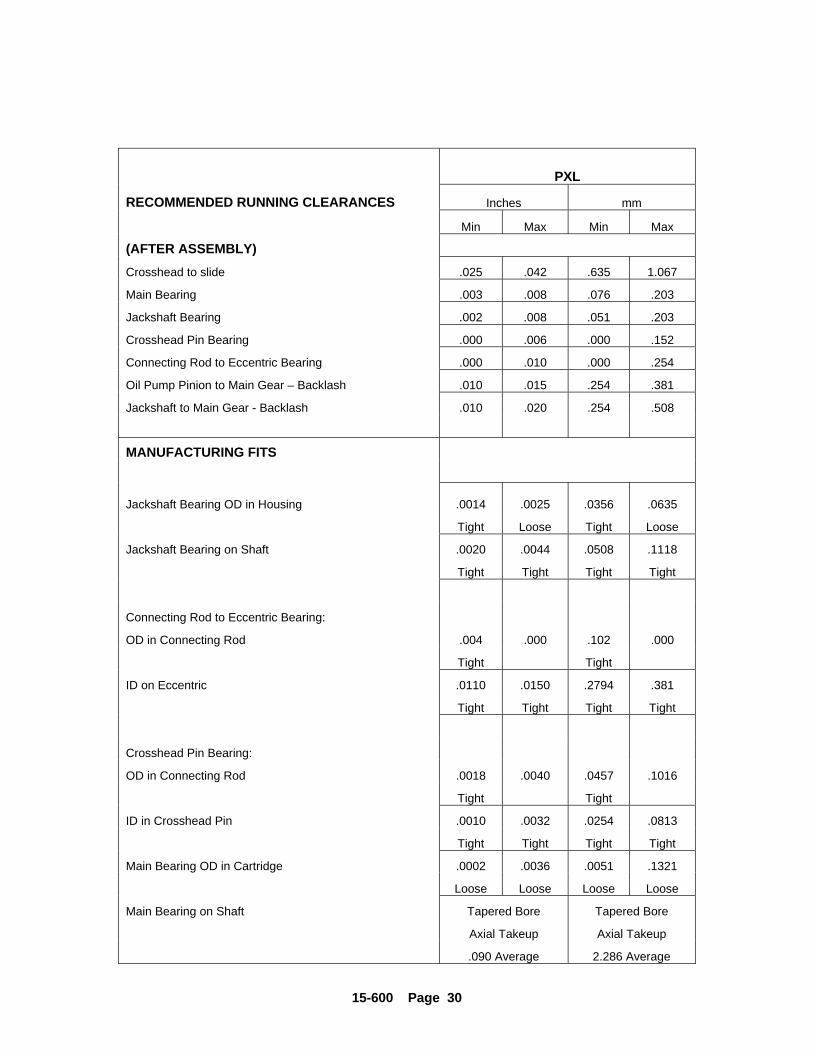
15-600 Page 30
PXL
RECOMMENDED RUNNING CLEARANCES Inches mm
Min Max Min Max
(AFTER ASSEMBLY)Crosshead to slide .025 .042 .635 1.067
Main Bearing .003 .008 .076 .203
Jackshaft Bearing .002 .008 .051 .203
Crosshead Pin Bearing .000 .006 .000 .152
Connecting Rod to Eccentric Bearing .000 .010 .000 .254
Oil Pump Pinion to Main Gear – Backlash .010 .015 .254 .381
Jackshaft to Main Gear - Backlash .010 .020 .254 .508
MANUFACTURING FITS
Jackshaft Bearing OD in Housing .0014 .0025 .0356 .0635
Tight Loose Tight Loose
Jackshaft Bearing on Shaft .0020 .0044 .0508 .1118
Tight Tight Tight Tight
Connecting Rod to Eccentric Bearing:
OD in Connecting Rod .004 .000 .102 .000
Tight Tight
ID on Eccentric .0110 .0150 .2794 .381
Tight Tight Tight Tight
Crosshead Pin Bearing:
OD in Connecting Rod .0018 .0040 .0457 .1016
Tight Tight
ID in Crosshead Pin .0010 .0032 .0254 .0813
Tight Tight Tight Tight
Main Bearing OD in Cartridge .0002 .0036 .0051 .1321
Loose Loose Loose Loose
Main Bearing on Shaft Tapered Bore Tapered Bore
Axial Takeup Axial Takeup
.090 Average 2.286 Average
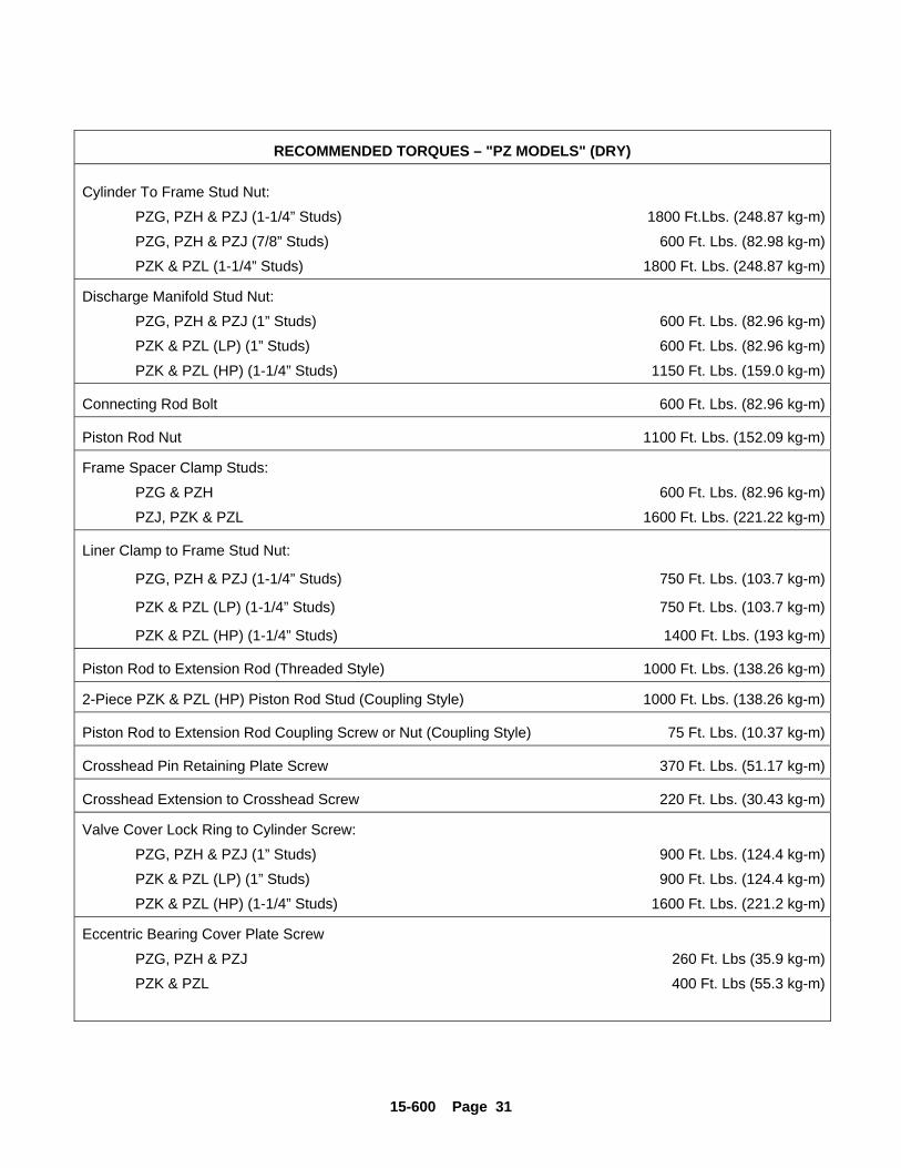
15-600 Page 31
RECOMMENDED TORQUES – "PZ MODELS" (DRY)
Cylinder To Frame Stud Nut:
PZG, PZH & PZJ (1-1/4” Studs) 1800 Ft.Lbs. (248.87 kg-m)
PZG, PZH & PZJ (7/8” Studs) 600 Ft. Lbs. (82.98 kg-m)
PZK & PZL (1-1/4” Studs) 1800 Ft. Lbs. (248.87 kg-m)
Discharge Manifold Stud Nut:
PZG, PZH & PZJ (1” Studs) 600 Ft. Lbs. (82.96 kg-m)
PZK & PZL (LP) (1” Studs) 600 Ft. Lbs. (82.96 kg-m)
PZK & PZL (HP) (1-1/4” Studs) 1150 Ft. Lbs. (159.0 kg-m)
Connecting Rod Bolt 600 Ft. Lbs. (82.96 kg-m)
Piston Rod Nut 1100 Ft. Lbs. (152.09 kg-m)
Frame Spacer Clamp Studs:
PZG & PZH 600 Ft. Lbs. (82.96 kg-m)
PZJ, PZK & PZL 1600 Ft. Lbs. (221.22 kg-m)
Liner Clamp to Frame Stud Nut:
PZG, PZH & PZJ (1-1/4” Studs) 750 Ft. Lbs. (103.7 kg-m)
PZK & PZL (LP) (1-1/4” Studs) 750 Ft. Lbs. (103.7 kg-m)
PZK & PZL (HP) (1-1/4” Studs) 1400 Ft. Lbs. (193 kg-m)
Piston Rod to Extension Rod (Threaded Style) 1000 Ft. Lbs. (138.26 kg-m)
2-Piece PZK & PZL (HP) Piston Rod Stud (Coupling Style) 1000 Ft. Lbs. (138.26 kg-m)
Piston Rod to Extension Rod Coupling Screw or Nut (Coupling Style) 75 Ft. Lbs. (10.37 kg-m)
Crosshead Pin Retaining Plate Screw 370 Ft. Lbs. (51.17 kg-m)
Crosshead Extension to Crosshead Screw 220 Ft. Lbs. (30.43 kg-m)
Valve Cover Lock Ring to Cylinder Screw:
PZG, PZH & PZJ (1” Studs) 900 Ft. Lbs. (124.4 kg-m)
PZK & PZL (LP) (1” Studs) 900 Ft. Lbs. (124.4 kg-m)
PZK & PZL (HP) (1-1/4” Studs) 1600 Ft. Lbs. (221.2 kg-m)
Eccentric Bearing Cover Plate Screw
PZG, PZH & PZJ 260 Ft. Lbs (35.9 kg-m)
PZK & PZL 400 Ft. Lbs (55.3 kg-m)
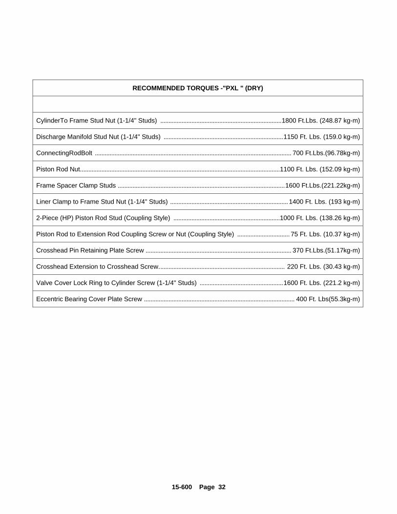
15-600 Page 32
RECOMMENDED TORQUES -"PXL " (DRY)
CylinderTo Frame Stud Nut (1-1/4" Studs) ..........................................................................1800 Ft.Lbs. (248.87 kg-m)
Discharge Manifold Stud Nut (1-1/4" Studs) .........................................................................1150 Ft. Lbs. (159.0 kg-m)
ConnectingRodBolt ........................................................................................................................ 700 Ft.Lbs.(96.78kg-m)
Piston Rod Nut..........................................................................................................................1100 Ft. Lbs. (152.09 kg-m)
Frame Spacer Clamp Studs ......................................................................................................1600 Ft.Lbs.(221.22kg-m)
Liner Clamp to Frame Stud Nut (1-1/4" Studs) ........................................................................ 1400 Ft. Lbs. (193 kg-m)
2-Piece (HP) Piston Rod Stud (Coupling Style) .................................................................1000 Ft. Lbs. (138.26 kg-m)
Piston Rod to Extension Rod Coupling Screw or Nut (Coupling Style) ................................ 75 Ft. Lbs. (10.37 kg-m)
Crosshead Pin Retaining Plate Screw ......................................................................................... 370 Ft.Lbs.(51.17kg-m)
Crosshead Extension to Crosshead Screw............................................................................. 220 Ft. Lbs. (30.43 kg-m)
Valve Cover Lock Ring to Cylinder Screw (1-1/4" Studs) ...................................................1600 Ft. Lbs. (221.2 kg-m)
Eccentric Bearing Cover Plate Screw ............................................................................................ 400 Ft. Lbs(55.3kg-m)
PRODUCT WARRANTYGARDNER DENVER PETROLEUM PUMPS
15-600 Page 33
GENERAL PROVISIONS AND LIMITATIONSGardner Denver (the "Company") warrants to each
original retail purchaser ("Purchaser") of its newproducts, assemblies or parts from the Company or itsauthorized distributors that such products are, at thetime of delivery to the Purchaser, made with goodmaterial and workmanship. No warranty is made withrespect to:
1. Any product which has been repaired oraltered in such a way, in the Company'sjudgment, as to affect the product adversely.
2. Any product which has, in the Company'sjudgment, been subject to negligence,accident, or improper storage, improperinstallation, operation or application.(Examples: over-pressure, sand-outs,cavitation, corrosion, erosion or degradation).
3. Any product which has not been operated ormaintained in accordance with therecommendations of the Company.
4. Components or accessories manufactured,warranted and serviced by others.
5. Any reconditioned or prior owned product.
Claims for items described in (4) above should besubmitted directly to the manufacturer.
WARRANTY PERIODThe Company's obligation under this warranty is
limited to repairing or, at its option, replacing, duringnormal business hours at an authorized service facilityof the Company, any part or assembly which in theCompany’s judgment proved to have unsatisfactorymaterial or workmanship within the applicableWarranty Period as follows.
Except for the products or components listed below,and subject to the limitations and restrictions set forthin the “Disclaimer” section set forth below, theWarranty Period for all products is 1,250 hours ofoperation or three (3) months after start-up, not toexceed 120 days after delivery to Purchaser,whichever occurs first. The exceptions are as follows:
1. Power end is warranted for twelve (12) monthsfrom date of start-up or eighteen (18) monthsfrom date of delivery to the Purchaser,whichever occurs first.
2. Forged steel fluid cylinders are warranted formaterials and workmanship for 6 months fromthe date of installation or 18 months from thedate of delivery to the purchaser, which everoccurs first.
3. Repairs are warranted for 90 days from thedate of delivery, for the workmanship andmaterials of the new parts installed.
4. Weld repaired fluid ends and weld repairedcomponents are not warranted.
5. Expendable fluid end parts, including, but notlimited to, valves, valve parts, packing, linersand pistons, are not covered by this warrantydue to variable abrasive nature of materialpumped.
PRESERVATION ASSEMBLIES DESTINED FORSTORAGE
In order for warranty acceptance any pumpassembly not immediately installed or destined to be instorage or in transit for extended periods of time mustbe prepared for storage as defined in the Company’sLong Term Storage Procedure. This includes but isnot limited to:
Drain and thoroughly clean inside power endcrankcase.
Spray rust inhibiting oil on all bearing, machinedand inside surfaces of the power end.
Induce clean gear oil into any circulating pump,filter, heat exchanger and piping.
Remove valves, seats and plungers from the fluidend. Thoroughly clean and dry these parts and allinternal surfaces. Coat all cylinder bores, valvecovers and reusable expendable parts with rustpreventative.
Flush all water, and contaminants from pump,tanks, hoses and spray nozzles. Spray allcomponents with a rust inhibiting oil.
Rotate pump every 30 days to insure bearings areoiled.
At the expense of the Purchaser, any productproperly preserved must be inspected by anauthorized agent of the Company, prior to theCompany, granting any extended warranty beyondthat stated in this warranty.
LABOR TRANSPORTATION AND INSPECTIONThe Company will provide labor, by Company
representative or authorized service personnel, forrepair or replacement of any product or part thereofwhich in the Company's judgment is proved not to beas warranted. Labor shall be limited to the amountspecified in the Company's labor rate schedule. Laborcosts in excess of the Company rate schedules causedby, but not limited to, location or inaccessibility of theequipment, or labor provided by unauthorized servicepersonnel is not provided for by this warranty.
PRODUCT WARRANTYGARDNER DENVER PETROLEUM PUMPS
15-600 Page 34
All costs of transportation of product or partsclaimed not to be as warranted and, of repaired orreplacement parts to or from such service facility shallbe borne by the Purchaser. The Company may requirethe return of any part claimed not to be as warranted toone of its facilities as designated by the Company,transportation prepaid by the Purchaser, to establish aclaim under this warranty.
Replacement parts provided under the terms of thiswarranty are warranted for the remainder of theWarranty Period of the product upon which installed tothe same extent as if such parts were originalcomponents.
The Company may request a root cause analysisbe performed in-order to identify if a request forwarranty claim meets the requirements of thiswarranty.
DISCLAIMERExcept as to title, the foregoing warranty is the sole
and exclusive warranty of the Company. TheCompany hereby extends other manufactures’warranty or guaranties, if any given to Company bysuch manufacturer, but only to the extent the Companyis able to enforce such warranty or guaranties. TheCompany has not authorized any party to make anyrepresentation or warranty other than as expressly setforthherein. SELLER HEREBY DISCLAIMS ANDEXCLUDES ANY OTHER EXPRESS, IMPLIED ORSTATUTORY WARRANTIES, ARISING BYOPERATION OF LAW OR OTHERWISE, INCLUDING,WITHOUT LIMITATION, ANY WARRANTIES OFMERCHANTABILITY OR FITNESS FOR APARTICULAR PURPOSE. COMPANY MAKES NOWARRANTIES OR REPRESENTATIONS OF ANYKIND WHATSOEVER (EXPRESS, IMPLIED ORSTATUTORY), OF LAW OR OTHERWISE, ON ANYEQUIPMENT, COMPONENT PARTS ORACCESSORIES SOLD HEREUNDER WHICH, ARENOT MANUFACTURED BY COMPANY.
NOTWITHSTANDING ANYTHING HEREIN TOTHE CONTRARY, THE FOREGOING WARRANTYSHALL BE THE SOLE AND EXCLUSIVE REMEDYAVAILABLE TO THE PURCHASER. UNDER NO
CIRCUMSTANCES, WHETHER IN CONTRACT,TORT OR OTHERWISE, SHALL THE COMPANY’STOTAL LIABILITY ARISING IN CONNECTION WITHANY PURCHASE ORDER EXCEED THE AMOUNTOF ANY SALES OR OTHER PROCEEDS RECEIVEDPURSUANT THERETO. IN ADDITION, UNDER NOCIRCUMSTANCES, WHETHER IN CONTRACT,TORT OR OTHERWISE, SHALL THE COMPANY BELIABLE FOR LIQUIDATED, SPECIAL, INDIRECT,INCIDENTAL, EXEMPLARY, OR CONSEQUENTIALDAMAGES, EXPENSES OR COSTS, INCLUDING,WITHOUT LIMITATION, LOST PROFITS ORFACILITY DOWNTIME, HOWEVER CAUSED ANDEVEN IF THE POTENTIAL OF SUCH DAMAGESWAS DISCLOSED AND/OR KNOWN.
No statement, representation, agreement, orunderstanding, oral or written, made by any agent,distributor, representative, or employee of theCompany which is not contained in this Warranty willbe binding upon the Company unless made in writingand executed by an officer of the Company.
This warranty shall not be effective as to any claimwhich is not presented within 30 days after the dateupon which the product is claimed not to have been aswarranted. Any action for breach of this warranty mustbe commenced within one year after the date uponwhich the cause of action occurred.
Any adjustment made pursuant to this warrantyshall not be construed as an admission by theCompany that any product was not as warranted.
WARRANTY REQUESTSProducts to be returned for warranty analysis shall be
approved for return in writing by the Company prior toshipment. All requests for product return shall besubmitted by email. Facsimile or letter to:
Warranty Department c/o Gardner Denver Petroleum Pumps
4747 South 83rd East AvenueTulsa, Oklahoma 74145
Email: [email protected]: (918) 664-6225
For additional information contact your local representative orGardner Denver Compressor and Pump Division,1800 Gardner Expressway, Quincy, Illinois 62301Customer Service Department Telephone:(800) 682-9868 FAX: (217) 224-7814Sales and Service in all major cities.
For parts information, contact Gardner Denver,Master Distribution Center, Memphis, TNTelephone: (800) 245-4946 FAX: (901) 542-6159
Specifications subject to change without notice.Copyright © 1999 Gardner Denver, Inc. Litho in U.S.A.
http://www.gardnerdenver.com