PV Development and Grid Access Study for a Club … · PV Development and Grid Access Study for a...
16
1 PV Development and Grid Access Study for a Club Resort in Indonesia Dr. Matthias Eichelbrönner Managing Director E.Quadrat GmbH & Co. Energy Experts KG PV Project Development by Horst Kruse, Jakarta On behalf of GIZ Indonesia, Promotion of Least Cost Renewables in Indonesia (LCORE) Study works supported by GIZ Indonesia, Promotion of Least Cost Renewables in Indonesia (LCORE), www.lcore-indonesia.or.id
Transcript of PV Development and Grid Access Study for a Club … · PV Development and Grid Access Study for a...

1
PV Development and Grid Access Study for a Club Resort in Indonesia
Dr. Matthias EichelbrönnerManaging Director
E.Quadrat GmbH & Co. Energy Experts KG
PV Project Development byHorst Kruse, Jakarta
On behalf of
GIZ Indonesia, Promotion of Least Cost Renewables in Indonesia (LCORE)
Study works supported by
GIZ Indonesia, Promotion of Least Cost Renewables in Indonesia (LCORE), www.lcore-indonesia.or.id

E.Quadrat Energy Experts2
1. Maumere Club Resort and PV Project
2. Electrical Infrastructure on the Maumere Island
3. Grid Measurements and Data Evalutation

Location and Project Target
� North coast of Flores Island
about 10 km from nearby town of
Maumere.
� Sea World Club (SWC) is a sea
side resort with gross land area
approximately 2.16 hectars and
consist of 25 bungalows.
� GIZ LCORE intends to initiate a
pilot PV project, considering:
� Energy consumption to be covered byPV on a net metering basis (yearlybalance).
� Grid downtime should be bridged by abattery storage system.
Maumere
E.Quadrat Energy Experts3

� Electricity supply: 20 kV/380 V transformer 100 kVA
� Supplier: PT PLN through their 8 MW diesel powered grid network (02/2013)
� Customers: private customers and the sea resort
� The installed capacity of the resort: 41.5 kVA, at 380/220 VAC
� The PLN connection point of the sea resort is in the generator house
� The distance between transformer and the generator house is about 300m
Power Supply and Conditions
E.Quadrat Energy Experts4

Solar System - Principal Design
Manual Transfer Switch 1
(Grid/Generator supply)
Sunny Tripower TL 17000
Sunny Island 8.0H mitMulticluster Box 6
Manual Transfer Switch
Sunny Island 8.0H Grid or Generator STP Switch On/Off Grid
Battery: 2 blocks each 1000Ah/48VDC
PLN Grid
E.Quadrat Energy Experts5

E.Quadrat Energy Experts6
1. Maumere Club Resort and PV Project
2. Electrical Infrastructure on the Maumere Island
3. Grid Measurements and Data Evalutation
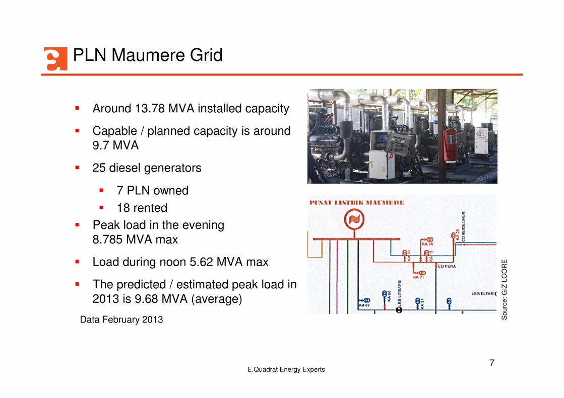
PLN Maumere Grid
� Around 13.78 MVA installed capacity
� Capable / planned capacity is around
9.7 MVA
� 25 diesel generators
� 7 PLN owned
� 18 rented
� Peak load in the evening
8.785 MVA max
� Load during noon 5.62 MVA max
� The predicted / estimated peak load in
2013 is 9.68 MVA (average)
Data February 2013 Sourc
e: G
IZ L
CO
RE
E.Quadrat Energy Experts7

Overview PLN Maumere DGS Busbar
E.Quadrat Energy Experts8
Sourc
e: G
IZ L
CO
RE

Overview 20 kV Distribution Network and Measuring Points
E.Quadrat Energy Experts9
Sourc
e: G
IZ L
CO
RE

E.Quadrat Energy Experts10
1. Maumere Club Resort and PV Project
2. Electrical Infrastructure on the Maumere Island
3. Grid Measurements and Data Evalutation

Load-Management and Grid-Evaluation
� Detailed grid measurement and evaluation
� Grid monitoring for technicalreliable interconnection
� Evaluation influence PV-Systembefore and after installation
� Further grid studies for next-stepdecentralized PV-Systems
� Diesel Generator operation strategy
� Diesel-Fuel Consumption
E.Quadrat Energy Experts11

Example Grid Measurement before PV Installation
Findings:
� Voltage fluctuations205 to 236 V
� Asymmetric phase voltage
� Asymmetric demand to be assumed
Question:
� Maximum PV power feasible?
12E.Quadrat Energy Experts
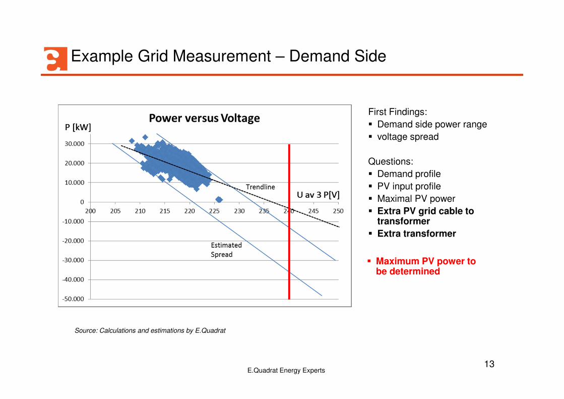
Example Grid Measurement – Demand Side
First Findings:
� Demand side power range
� voltage spread
Questions:
� Demand profile
� PV input profile
� Maximal PV power
� Extra PV grid cable to transformer
� Extra transformer
Source: Calculations and estimations by E.Quadrat
� Maximum PV power to be determined
13E.Quadrat Energy Experts

Evaluation of Parameters to define max PV installation
E.Quadrat Energy Experts14
-40.000
-30.000
-20.000
-10.000
0
10.000
20.000
30.000
210 215 220 225 230 235 240
Gradient of Downstream System:
∆U : ∆P = const.
8 V : 20 kW = 0,4 V/kW
Depending on downstream loadand electrical parameters
PV max: 10 kW + abs (-30 kW) = 40 kW
PV max: 10 kW + abs (-40 kW) = 50 kW
Spread of Upstream System:
∆U = 221 V – 212 V = 9 V
Depending on upstream loadand electrical grid parameters
∆U
System Voltage [V]
Dow
nstr
eam
Load [kW
] Evaluation of the crucial time between 11.00 hrs to 14.00 hrsover one week.
- Voltage spread due to upstream load changes
- Majority operational point A
- Minority operational points B, C
- Gradient voltage to load behavior downstream
A BC
PV max (net AC) = downstream loadmin + abs (- P240VAC)
Maxim
um
Sys
tem
Voltage
[V]
Source: Calculations and estimations by E.Quadrat

Conclusions
� Recommended PV installation at SWC: 60 kW peak
PV max connection point = 50 kW (net) + 20% (losses due to PR)
� Grid data evaluation developed methodology to estimate maximum
PV power
� Methodology evaluates specific grid data as
� Voltage to load Downstream gradient
� Voltage spread of Upstream system behavior
from grid connection point.
E.Quadrat Energy Experts15

E.Quadrat GmbH & Co. Energy Experts KGWeinheimerstraße 64a68309 Mannheim
Handelsregister MannheimHRA 702149
Telefon +49/(0)621/762 209 6-0
www.equadrat-gmbh.eu
E.Quadrat GmbH
Thank You forYour Attention!