Protective systems against - · PDF filemake necessary a super-industrialisation with a...
60
Transcript of Protective systems against - · PDF filemake necessary a super-industrialisation with a...

Protective systems against hazards
Nature and extent of the problem
Technical report prepared by a Working Group
of former FIP Commission 8
October 1999

Subject to priorities defined by the Steering Committee and the Praesidium, the results of fib’s work in Commissions and Task Groups are published in a continuously numbered series of technical publications called 'Bulletins'. The following categories are used:
category minimum approval procedure required prior to publication
Technical Report approved by a Task Group and the Chairpersons of the Commission State-of-Art report approved by a Commission Manual or Guide (to good practice)
approved by the Steering Committee of fib or its Publication Board
Recommendation approved by the Council of fib Model Code approved by the General Assembly of fib
Any publication not having met the above requirements will be clearly identified as preliminary draft.
This Bulletin N° 5 has been approved as a fib technical report in April 1999 by fib Commission 3 ‘Environmental aspects of design and construction’.
The former FIP Working Group on ‘Protective systems against hazards’ started in 1988. CEB and FIP merged in 1998 into fib. This report, therefore, was published in the new fib series of bulletins:
K. van Breugel* (The Netherlands, chairman of Working Group), H. Bomhard* (Germany, chairman of former FIP Commission 8 ‘Concrete Storage Vessel Systems’, later named ‘Concrete and Environment’), S. R. Close* (USA), M. Fenz † (Austria), A. R. Frankson (USA), H. R. Ganz (France), I. Jorgensen (USA), V. Kaltofen* (Germany), P. Marti (Switzerland), J. Nemet (Austria), G. Opschoor (The Netherlands), V. Papenhausen (Germany), M. Ronde (The Netherlands), D. Rudat* (Germany) * Main contributors to this publication
Full affiliation details of most Task Groups members may be found in the fib Directory. Cover photo: Risk spectra (according to Bomhard, see fig. 2.4 and Reference 11) © fédération internationale du béton (fib), 1999 Although the International Federation for Structural Concrete fib - féderation internationale du béton - created from CEB and FIP, does its best to ensure that any information given is accurate, no liability or responsibility of any kind (including liability for negligence) is accepted in this respect by the organisation, its members, servants or agents. All rights reserved. No part of this publication may be reproduced, stored in a retrieval system, or transmitted in any form or by any means, electronic, mechanical, photocopying, recording, or otherwise, without prior written permission. First published 1999 by the International Federation for Structural Concrete (fib) Post address: Case Postale 88, CH-1015 Lausanne, Switzerland Street address: Federal Institute of Technology Lausanne - EPFL, Département Génie Civil Tel (+41.21) 693 2747, Fax (+41.21) 693 5884, E-mail [email protected] ISSN 1562-3610 ISBN 2-88394-045-2 Printed by Sprint-Druck Stuttgart

List of Contents page Foreword and Executive Summary iv Preface vi Chapter 1 Introduction 1.1 The environment in danger 1 1.2 Picturing the problem 1 1.3 Solutions 4 1.4 Protective structures 5 Chapter 2 Safety Concepts - The role of structural protective systems 2.1 Safety concepts 7 2.2 The risk concept 7 2.3 Consequence control 11 2.4 Safety promoting methods 12 2.5 System Technology 14 2.6 Structural protective systems 14 2.7 Why concrete protective structures? 16 2.8 Deterministic levels of protection 17 2.9 Merits of protective systems 18 2.10 Summary 19 Chapter 3 Hazard Actions 3.1 General 21 3.2 Blast 21 3.3 Thermal actions 23 3.4 Impacts 25 3.5 Earthquakes 28 3.6 Natural phenomena 29 3.7 Hazardous materials 29 Chapter 4 Hazards Scenarios 4.1 Scenario thinking 35 4.2 Industrial accidents 35 4.3 Hazard scenario schemes 37 4.4 Examples of waste hazard scenarios 38 Chapter 5 Examples and Developments 5.1 Introduction 43 5.2 LPG-storage tank 43 5.3 Inground and in-pit solutions 44 5.4 A-seismic design of tank systems 44 5.5 Prestressed concrete pressure vessels 45 5.6 Blast resistant control building 46 5.7 Multi-barrier waste storage system 48 5.8 Buried multi-barrier storage systems 52 5.9 Final comments 53 References 55
Copyright fib, all rights reserved. This PDF copy of fib Bulletin 5 is intended for use and/or distribution only by National Member Groups of fib.

fib Bulletin 5: Protective systems against hazards iv
Foreword and Executive Summary In every society, risks are being permanently produced. New kinds of technical developments and new means of satisfying needs create permanent risks. This is particularly noticeable when societies develop into service societies. These embody an enormous increase in prosperity, but at the same time make necessary a super-industrialisation with a greatly increased danger potential. For some time now the risk potential in our highly technically industrialised world has been growing more quickly than investments in safety measures. This makes society more vulnerable and implies danger. A measure of the size of danger is given with the term “risk”, and protection is a form of preventive measures to avert danger. The risk R is usually defined as the product of the probability Pf of a damaging event and the consequential damage C of the event: R = Pf x C. Below a limit delineated by the relevant practical experience, all indications of probability have a purely hypothetical, speculative character. All damaging events beyond a still tolerable consequential damage Climit represent catastrophic events that must be avoided (see Figure 2.4). Therewith we are concerned with great differences in risk categories. I will elaborate this by discus-sing characteristic risk structures: • Risk category 1.
Usual structures risks with normal damage potential, e.g.: - bridges; - high-rise buildings, etc.
• Category 2. Large-scale industrial risks with catastrophic risk potential, e.g.: - Mexico City 1984, the catastrophe involving liquid gas; - Bhopal/India 1985, the catastrophe involving methylisocyanate; - Seveso; - Sandoz, etc.
• Risk category 3. Large-scale industrial risks with catastrophic risk potential, but with a probability of occurrence that cannot be quantified, e.g.: - storage and reactor systems for material of unknown composition and effect, for example
wastes, irrespective of whether they are of industrial or household origin. • Risk category 4.
Large-scale industrial risks with a very high damage potential, C → ∞, and a very small probability of occurrence, Pf → 0, e.g.: - nuclear power plants.
Risks of categories 3 and 4 make clear the weakness of our present safety philosophy, which means safety on the basis of the risk involved. In both categories the risk R cannot be quantified – not for category 3, because the probability of failure, for example of a container for materials with an un-known composition and effect – for example a landfill for wastes – is not quantifiable, and not for category 4, because the situation “zero multiplied by infinity” is singular and can mean anything. Risks of category 2 can, this is true, be quantified, but catastrophes such as those in Mexico City and in Bophal are not acceptable either. To take precaution against risks causing catastrophic damage is indispensable also under ecological, economical and social aspects according to the paradigm of sustainability dictated by the Agenda 21 signed in Rio 1992 by 179 nations. Under these circumstances, protection cannot and must not continue to be orientated predominantly to the risk of an accident, but must concentrate on the damage, more particularly on a “residual dam-age”, identical to a tolerable upper limit for damage C ≤ Climit. “Residual risk” has to be replaced by
Copyright fib, all rights reserved. This PDF copy of fib Bulletin 5 is intended for use and/or distribution only by National Member Groups of fib.

Foreword and executive summary
v
“Residual damage”. Damage limitation is feasible reliably only if implemented deterministically by using passive means, with material barriers in the form of structural safety containments. With this philosophy the safety objective can be defined in precise terms as “The entire impact caused by accidents must remain restricted to the inside of the safety containment, to protect human life and the environment from harmful releases”. That is our answer to the question “How safe is safe enough?” in dealing with hazardous materials and processes. Because of their robustness, concrete components have to from the integral part used in any barrier. Thanks to wall thickness, heat capacity and tension softening, they are extremely resistant to impacts, shocks and penetrations, as well as fire and cryogenic attacks – to name just some of the effects in-volved in accidents. If tightness requirements are prevailing the residual damage, the structural integrity is inadequate and the full integrity, including tightness, of the barrier must be guaranteed. Tightness is best defined in terms of a tolerable leakage rate. Concrete is properly tight, but problems may be caused by cracks, in particular separation cracks. Cracks can be avoided or their depth restricted if we prestress concrete. In this way tightness can be influenced and controlled with regard to quality and quantity almost at will and is then almost reliable. Coatings or linings are needed if this is not sufficient, for example if the uncracked or partly cracked concrete is too permeable for the substance affecting it. The integrity of these sealing layers is then normally dependent on the degree of prestressing. The criterion for this is once more the state of the cracks. We will not, of course, rely only on passive safety, but combine it with active forms, so that both complement each other. I would like to thank the members of the Working Group, specially the Chairman, Dr. Klaas van Breugel, for this work, dealing successfully with an outstanding subject in a very efficient manner. Being committed engineers and scientists the group accepted the challenge to write this important report, important for society and industry as well, to open up new ways to a sustainable development of our world. Part 2 of the report is somewhat drafted, Part 3 just roughly structured. I wish and I hope that the Working Group, now under the new leadership of fib, will be able to bring both parts to the end with engagement, competence and success. Munich, December 1998 Helmut Bomhard Chairman FIP Commission 8, The Commission on “Concrete and Environment”
Copyright fib, all rights reserved. This PDF copy of fib Bulletin 5 is intended for use and/or distribution only by National Member Groups of fib.
vi fib Bulletin 5: Protective systems against hazards
Preface The enormous growth in scale and complexity of modern industrial facilities, and the associated increase in consumption of energy and raw materials, has put the environment under pressure. Pressure in terms of depletion of basic resources and of safety. Large-scale industrial accidents and severe pollution of the biosphere, as well as detailed analyses of hazard scenarios, have revealed the need for reconsidering currently used safety concepts. Among the many aspects involved in such a process of reconsideration, the protection of the environment is one of the important issues. This report is the first of a series of three reports on structural protective systems against hazards. This first report deals with the nature and extent of the problem. Currently used safety concepts are briefly mentioned and evaluated. A survey of hazards and hazard scenarios further illustrates the weak points in traditional solutions. This evaluation reveals that the adoption of concrete structures can substantially enhance the safety of people and of the environment. Some examples of concrete protective structures are presented, showing the potentialities of concrete structures for reliable protection. The second report of this series will deal with design tools for the structural engineer who is in charge for designing protective structures. These design tools may refer to either hazard actions, the materials behaviour and / or the structural response. In the third report examples of concrete protective systems will be presented in more detail. The material for this report has been brought together by a small group of experts from the chemical and the building industry, consultants, authorities and the academic world. The input of individual members consisted of active participation in meetings of the working group and corresponding membership. The working group was part of the former FIP Commission 8 "Concrete Storage Vessel Systems". After the merger of FIP and CEB in May 1998, the work has been and will continue in the framework of fib Commission 3 “Environmental Aspects of Design and Construction”. Delft, October 1999 Klaas van Breugel Chairman Working Group on Concrete Protective Systems
Copyright fib, all rights reserved. This PDF copy of fib Bulletin 5 is intended for use and/or distribution only by National Member Groups of fib.

1. Introduction
1
1 Introduction 1.1 The Environment in Danger In recent decades industrial activities and industrial facilities have shown an enormous growth, both in scale and complexity. This growth is accompanied by a large increase in energy consumption and use of raw materials, an increase in production of consumer goods and waste as a by-product. Storage and pro-cessing of raw materials and energy carriers often take place in large quantities in extensive facilities. The size and complexity of modern facilities make them more and more non-transparent and difficult to survey. This makes these facilities susceptible to trouble, which may result in heavy damage in case of an accident. Although scale and complexity are not a problem per se, the combination with storage and pro-cessing of ever-larger quantities and concentrations of potentially dangerous substances constitute a tech-nical, social and environmental hazard. A hazard is de-fined here, in line with Blockey [21], as "a set of conditions in the operation of a product or system, with the potential for initiating an accident sequence". Well-performed risk and consequence analyses have evidenced the gravity of the present situation. Even more convincing than these analyses is the impressive list of past industrial and man-made environmental catastrophes. More than ever before it is recognised that the consequences of industrial activities, industrial catastrophes and environmental problems are border-crossing and even exhibit global dimensions. Large areas of fertile land have been converted into vast contaminated territories, inaccessible for man on penalty of health problems. There is no doubt any more: The environment is in danger! Faced with these problems the question arises if, and how, structural engineering can contribute to solve, or at least alleviate, these problems. In order to answer this question we first have to concentrate on the nature and the extent of today and prognosticated problems. 1.2 Picturing the problem Consumption of energy and raw materials The majority of present problems is closely related to the increasing use of energy and raw materials. Since the population of the world and the consumption of energy and raw materials per capita is forecasted still to increase drastically in coming decades, it is to be expected that the hazard potential will increase as well. Statistics is quite convincing in this respect. Figure 1.1 shows the increase in energy consumption in past and coming decades.
Copyright fib, all rights reserved. This PDF copy of fib Bulletin 5 is intended for use and/or distribution only by National Member Groups of fib.

fib Bulletin 5: Protective systems against hazards
2
Fig. 1.1 Energy scenarios after different authors [1]
Fig. 1.2 Major industrial catastrophes as a Fig. 1.3 Estimated direct and long-term losses function of energy consumption. Of the Chernobyl disaster. Estimates from Period ‘54-’84, (based on data in [20]) 1986 [19] and 1990 For the reference period from 1954 to 1984, Fig. 1.2 shows the correlation between energy consumption and the number of industrial accidents per year with direct losses exceeding $ 10,000,000. In many accidents this amount was exceeded by a factor of ten or even more. The direct losses in the Mexico LPG
50TWa/a
40
30
20
10
01860 1900 1940 1980 2020 2060
year
unknowngeothermalsolar energy
wind
gas
biomass (new)
hydro power
biomass (trad.)
nuclear power
coaloil
number of accidents/year7
6
5
4
3
2
1
0
energy consumption per capita [kWa/a]2 4 6 8 10 12 14 16 18 200
~1980
~1950
US $ [10 ]9
50
40
30
20
10
years5 10 15 20 25 300
0
estimation 1990
estimation 1986
1986 1990
long term loss
short term loss
Copyright fib, all rights reserved. This PDF copy of fib Bulletin 5 is intended for use and/or distribution only by National Member Groups of fib.

1. Introduction
3
disaster in 1984, for example, amounted to over $ 150,000,000. Figure 1.2 also teaches us that, in spite of increasing awareness of industrial and technological risks, the growing investments in safety systems in re-cent decades have at best been enough to compensate for the increased probability of large accidents associated with the increased scale and complexity of modern industrial facilities. For a declining relationship between energy consumption and accident frequency either higher investments per unit of e-nergy are required or more effective safety concepts have to be developed. Indirect and long-term losses are generally much higher than the direct losses. This can be shown convincingly by referring to the losses experienced in the Chernobyl disaster. An indication of the losses caused by this catastrophe is given in Fig. 1.3. The direct losses were estimated at 4 to 5 billion US dollars. Indirect and long-term losses due to deprived income from lost crops have been estimated at ten and twenty billion US-dollars after ten and twenty years, respectively [8]. In these figures claims for losses experienced outside the former USSR have not been taken into account. These losses also exclude the costs for extra health care for those who still suffer from the consequences of this accident, including the care for recently born disabled children. More recent figures show, that four years after the accident the losses have already reached the level that was expected after 25 years! Catastrophes like the Chernobyl disaster and the nuclear accident in Harrisburg are examples of accidents, which, because of the huge and multi-disciplinary consequences, require special judgement. This issue is discussed in more detail in Chapter 2. Costs for preservation of the environment Huge amount of money is required to protect and clean contaminated soil and ground water. The costs of environmental damage in West Germany and the costs for cleaning of contaminated sites in the The Netherlands have been estimated at about $ 100 109 [4] and $ 30 109 [19], respectively. Related to a total population in these two countries of about ninety million people, the costs for rehabilitation amount to about $ 1,400/ capita. Based on an energy consumption in these countries of 6 kWa/a per capita, the costs per unit of energy consumed would be more than $ 230/kWa/a. The energy consumption in 1990 is, world wide, 11 TWa/a. Assuming the energy consumption to be an indicator for the present pollution potential, the total costs for cleaning of soil and ground water would be 11 109 . 230 = $ 2.5 1012. This amount can be considered as a rough indication of the amount required for preservation of the environment and is in rela-tively good agreement with the amount of $ 0.8 1012 mentioned by the World Watch Institute [2]. A sub-stantial portion of resources needed for rehabilitation and preservation of the environment will be converted to civil engineering projects. In this respect the upgrading and building of large sewage systems, building of storage systems for intractable hazardous wastes, catch basins for fire fighting water, structural provisions for protection of soil and ground water against leakage of hydrocarbons at petrol stations and scrapyards and storage systems for various types of intractable hazardous wastes can be mentioned. In almost all cases investing money in measures for protecting life and limb will in the end reveal to have been economically justified. The tremendously high costs for rehabilitation of the environment make it easy to believe this to be true. Apart from the question whether money spent on protective measures is econ-omically justified or not, it must be considered just a matter of responsible stewardship to convert money, knowledge and technology to preservation of the environment.
Copyright fib, all rights reserved. This PDF copy of fib Bulletin 5 is intended for use and/or distribution only by National Member Groups of fib.

fib Bulletin 5: Protective systems against hazards
4
Insurability of risks The financial consequences of large natural or man-made catastrophes may be so high, that these financial burdens have to be taken by insurance companies. If sufficient statistical data exists, quantitative risk assessment will be the basis for the premium these companies have to charge so that they will not run into financial problems themselves. When statistical data is scanty, however, as it is the case with so called Low Probability/High Consequence Risks, a basis for probability-based decision making becomes too uncertain to rely on. It is particularly in these cases, that for the insurance industry a risk is primarily considered a fi-nancial threat. In case an accident occurs they must be able to pay for the maximum loss, however small the probability of occurrence would have been estimated [34]. It is for this reason, that the insurance industry emphasises the control of consequences rather than the control of risks or the probability of occurrence of an accident. Moreover, when a variety of non-financial risk aspects are to be considered, like economic, social, political, psychological and environmental aspects, insuring of risks becomes very complicated, if not impossible. Here we touch upon the limits of what has been indicated with responsible stewardship or responsible care. Multi-Disciplinarity There is no doubt that something has to be done to escape from the vicious circle leading to further destruction of the environment. All scenarios that have been worked out recently clearly demonstrate that solutions of modern environmental and safety problems require a multi-disciplinary approach. Just as it must be judged incorrect and unfair to hold one single discipline responsible for the contemporary pro-blems, it would be unfair to expect comprehensive solutions from one single discipline. Reversely, it must also be judged unrealistic if one particular discipline would claim to have all-embracing solutions. Such a claim would only illustrate that the complexity and nature of environmental and safety problems have not been understood in full depth. 1.3 Solutions Technical-fix approach It has been stated that the present safety and environmental problems can be solved by a rigorous implementation of more technique and technology. This technical-fix approach presupposes that the nature of the problem is a technical, one-dimensional one. Instead of more traditional techniques, which may be more sophisticated, alternative methods would be needed, ending in perhaps an industrial revolution [35]. Against the background of the fact that today problems are predominantly technique-related, the technical-fix approach is still to be considered an untested hypothesis. Revolution of the industrialised society Instead of emphasising the potential of technique and technology as the most promising remedy for solving the problems of our industrialised society, we also find people who strongly support the need for a fundamental change of mentality. No longer the economic imperative of growth, but a re-evaluation and redefining of goals and norms for our society should be placed in the focus of attention. This change of mentality is not considered as the precondition for the realisation of an industrial revolution, but for a revol-ution of the industrialised society. By putting it in this way it is emphasised that the problems of the industrialised world can be solved neither by marginal changes of society nor by a major industrial revol-ution, nor even by the search for high-tech solutions of present problems, but the cause of all these prob-lems should be in the focus of attention. A thorough search for the cause of many safety and environmental problems reveals that it is not the shortcomings of technique and technology, but rather its successes that have caused them.
Copyright fib, all rights reserved. This PDF copy of fib Bulletin 5 is intended for use and/or distribution only by National Member Groups of fib.

1. Introduction
5
An important implication for the present generation of engineers inferred from the forgoing is, that not merely high-tech trouble shooting, but comprehensive judgement of our technical and technological achi-evements should be made to his key-duties. It is clear that such a comprehensive judgement is impossible without addressing people's world view [28]. Since worldviews may differ quite substantially, the con-vergence of ideas, the formulation of goals and norms and defining criteria will not be easy. One can judge this a problem, but also as a major challenge of our decade. The nature of the present problems requires the participation of a variety of disciplines, including the engineering discipline, in the discussion about the future of our society. The present generation of engineers should prepare themselves for their part in this discussion. It has to be admitted that, generally speaking, en-gineers are familiar primarily with technical issues. It is an inherent part of the required mentality change of our society, however, that engineers provide themselves not only with tools for solving technical problems, but also with an attitude to look first to the cause of the problems and concentrate on possibilities to anticipate them. The drastic consequences of large-scale industrial catastrophes and the increasing flow of information on the detrimental effects of the use of fossil energy carriers on the climate (green-house effect) and the pollu-tion of the environment have had a huge and negative impact on the appreciation of modern techniques and technology by society. Meanwhile everybody seems convinced that something has to be done to protect the environment and to guarantee safety of life and limb. It is the aim of this report to contribute to the interdisciplinary discussion on how to deal with severe risks in a modern industrialised society. This will be done by explaining the potentialities of protective systems for containment of large industrial catastrophes and for protecting the environment. 1.4 Protective structures The focus of attention when considering different solutions to solve the safety problem will be on the po-tential of concrete protective structures as part of a comprehensive safety strategy. Reasons for focusing on concrete as a superior material for the design of protective systems will be dealt with in detail in Chapter 2. In anticipation of that more detailed argumentation it is noticed here already that: • Concrete structures can be designed so as to resist a variety of extreme loading conditions like impacts,
fires, cryo-shocks, gas cloud explosions, airplane crashes and earthquakes; • A well-considered combination of concrete with reinforcing and prestressing steel enables not only a
robust and rigid design, but also ductile structures with high energy absorption capacity. • With addition of admixtures, extra fines and different types of steel and synthetic fibres, concrete can be
tailored so as to fulfil the most stringent requirements deterministically, even tightness criteria. By adjusting the shell thickness and thanks to the heat capacity, cold toughness and the softening behaviour when loaded in tension, concrete protective structures are resistant to heavy impact, perforation and thermal actions. It is these features of concrete structures, which make them unsurpassed for reliable consequence control. Why control of consequences is considered to be so important will be explained in the next chapter of this report.
Copyright fib, all rights reserved. This PDF copy of fib Bulletin 5 is intended for use and/or distribution only by National Member Groups of fib.

2. Safety concepts
7
2 Safety Concepts The role of structural protective systems 2.1 Safety Concepts In early primitive cultures people built structures to protect themselves. Protection was needed against the climate, extreme natural phenomena like tornadoes and floods and against wild animals. In a modern industrialised society things have changed drastically. The need for protection still exists. However, the objects which need protection are different. It is not merely people who need protection, but to an increasing extent also their industrial investments. Moreover, the hazards which have to be envisaged seem to be of another nature than before. The more people have intervened in natural and ecological systems and have tried to manage nature at will, the more this man-made environment appeared to change into a source of hazards. People have created their own enemy. They have to protect themselves against the man-made environment, the product of their own brains and activities. Moreover, they have to protect the natural environment against catastrophic pollution and deterioration processes caused by failing industrial processes and human errors. It can be conclude that people have to be protected against the consequences of both natural phenomena and the modern way of life. Discussions on whether the advantages of an industrialised society really counterbalance the inherent disad-vantages, generally concentrate on a comparison of risks. This risk concept has gained a lot of support in recent decades. Based on statistical accident data and accident scenarios, complex processes can be analysed and the weak points of complex systems can be traced in the design stage already. Large industrial catastrophes and increasing environmental problems have revealed, however, that a complete reconsidera-tion of the risk concept is needed. Such a reconsideration is needed in all those cases, where the event prob-abilities can not be checked because of a lack of statistical data and where the consequences of an accident may become extremely high. Moreover, also from a more fundamental, philosophical point of view the risk concept requires a critical re-appraisal [4,6,7]. Particularly since licensing and approval authorities seem to be prepared to tune acceptance criteria for risk-bearing activities to the outcome of Quantitative Risk Ana-lysis (QRA's). This development has raised a stream of criticism, partly maybe based without ground but partly on good reasons. To understand the reason for criticism, some basic features of the risk concept will be briefly discussed here. The evaluation of the risk concept automatically leads to the questions "How safe is safe enough" and "Are there realistic alternatives?" 2.2 The risk concept The principle First techniques for risk assessment date back to the 1930s and 1940s. Early applications of the risk concept are found in the insurance business. In the structural field first applications are found in aviation engineering [31]. In the traditional risk concept the risk R is de-fined as the product of the event probability P{F} and the consequences C of that event. In formula form: R = P{F} * C
Copyright fib, all rights reserved. This PDF copy of fib Bulletin 5 is intended for use and/or distribution only by National Member Groups of fib.

fib Bulletin 5: Protective systems against hazards 8
Fig. 2.1 Flow chart for decision making according to the conventional risk concept The probability of failure depends on the density functions of both the available resistance and the actions. The consequences can be expressed in the number of fatalities or in financial losses. By dividing the conse-quences, i.e. the number of fatalities per year, by the number of people living within the sphere of influence of the risk-bearing activities, the individual risk (per person per year) is obtained. For judging the acceptabi-lity of risk bearing activities the calculated risk R is compared with a risk criterion. This criterion has to be defined by an owner or by legislative authorities. Objectives With the introduction of the risk concept it was aimed, and claimed, to have an objective and rational tool for decision making. There is no doubt that the risk concept, and implicitly the Quantitative Risk Analysis (QRA), is a powerful tool for ranking of safety levels and tracing the vulnerable points of structures, sys-tems, facilities, processes and activities. At the same time, however, the risk concept has been judged inap-propriate for comprehensive judgement of risk-bearing industrial activities [4,8,9]. This would hold particularly in case of Low Probability/High Consequence Risks. In those cases the theoretical risks are rather uncertain because of the lack of statistical data concerning magnitude and character of the actions. The results of risk analyses are, therefore, considered to be of limited use in decision making processes [22]. Residual risk For risks below a certain small value the term "residual risk" has been introduced. A residual risk is the small theoretical risk that had to be accepted simply because of the fact that a zero-risk is not attainable within the framework of the risk concept. The residual risk principle, however, does in no way contribute to the control of consequences in case an accident occurs. On the contrary, it may free the way to justify and accept the introduction or continuation of risk bearing activities or processes, which should have been judged unacceptable if the activity in view would have been subjected to an integral judgement process in which all consequence aspects would have been taken into account [8]. In essence, a one-dimensional risk criterion, like a residual individual risk, has not the quality so as to make it an adequate parameter for judging risk bearing activities, techniques and technologies Integrally and comprehensively [53, 94]. Instead of judging against a one-dimensional criterion, a multi-dimensional approach has be to considered. This multi-dimensional approach is shown schematically in Fig. 2.2 as an Extended Risk Concept.
techniqueprocess, activity
structural system,technology
R = P{F} * C
accepted
R < R
R = RiskR = Acceptable RiskC = ConsequenceP = Probability of Failure
decreaseP{F} or C
no
yes
Copyright fib, all rights reserved. This PDF copy of fib Bulletin 5 is intended for use and/or distribution only by National Member Groups of fib.
2. Safety concepts
9
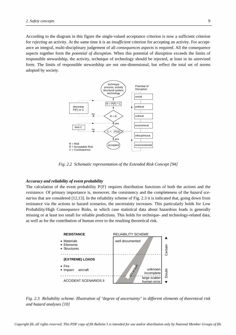
According to the diagram in this figure the single-valued acceptance criterion is now a sufficient criterion for rejecting an activity. At the same time it is an insufficient criterion for accepting an activity. For accept-ance an integral, multi-disciplinary judgement of all consequences aspects is required. All the consequence aspects together form the potential of disruption. When this potential of disruption exceeds the limits of responsible stewardship, the activity, technique of technology should be rejected, at least in its unrevised form. The limits of responsible stewardship are not one-dimensional, but reflect the total set of norms adopted by society.
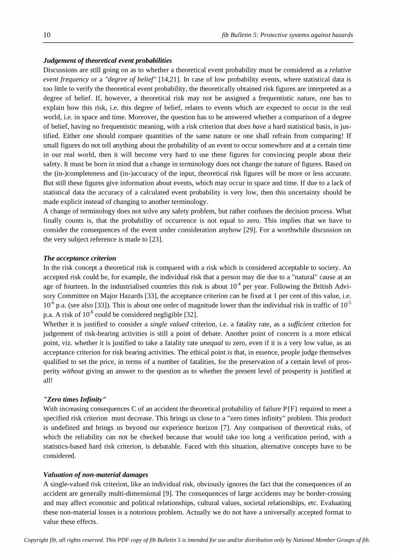
Fig. 2.2 Schematic representation of the Extended Risk Concept [94] Accuracy and reliability of event probability The calculation of the event probability P{F} requires distribution functions of both the actions and the resistance. Of primary importance is, moreover, the consistency and the completeness of the hazard sce-narios that are considered [12,13]. In the reliability scheme of Fig. 2.3 it is indicated that, going down from resistance via the actions to hazard scenarios, the uncertainty increases. This particularly holds for Low Probability/High Consequence Risks, in which case statistical data about hazardous loads is generally missing or at least too small for reliable predictions. This holds for technique- and technology-related data, as well as for the contribution of human error to the resulting theoretical risk.
Fig. 2.3 Reliability scheme. Illustration of "degree of uncertainty" in different elements of theoretical risk and hazard analyses [10]
RESISTANCE RELIABILITY SCHEME
(EXTREME) LOADS
MaterialsElementsStructures
well documented
FireImpact aircraft unknown
incompletelarge scatterhuman errorACCIDENT SCENARIOS II
unce
rtain
Cer
tain
Dou
bt
no
yes
yes
no
decreaseP{F} or C
techniqueprocess, activity
structural system,technology
R = P{F} * C
R < R
limit C
environmental
ethical/moral
economical
cultural
R = RiskR = Acceptable RiskC = Consequence
political
social
Potential ofDisruption
C < POD
accepted
Dou
bt
C
erta
in
Copyright fib, all rights reserved. This PDF copy of fib Bulletin 5 is intended for use and/or distribution only by National Member Groups of fib.
fib Bulletin 5: Protective systems against hazards 10
Judgement of theoretical event probabilities Discussions are still going on as to whether a theoretical event probability must be considered as a relative event frequency or a "degree of belief" [14,21]. In case of low probability events, where statistical data is too little to verify the theoretical event probability, the theoretically obtained risk figures are interpreted as a degree of belief. If, however, a theoretical risk may not be assigned a frequentistic nature, one has to explain how this risk, i.e. this degree of belief, relates to events which are expected to occur in the real world, i.e. in space and time. Moreover, the question has to be answered whether a comparison of a degree of belief, having no frequentistic meaning, with a risk criterion that does have a hard statistical basis, is jus-tified. Either one should compare quantities of the same nature or one shall refrain from comparing! If small figures do not tell anything about the probability of an event to occur somewhere and at a certain time in our real world, then it will become very hard to use these figures for convincing people about their safety. It must be born in mind that a change in terminology does not change the nature of figures. Based on the (in-)completeness and (in-)accuracy of the input, theoretical risk figures will be more or less accurate. But still these figures give information about events, which may occur in space and time. If due to a lack of statistical data the accuracy of a calculated event probability is very low, then this uncertainty should be made explicit instead of changing to another terminology. A change of terminology does not solve any safety problem, but rather confuses the decision process. What finally counts is, that the probability of occurrence is not equal to zero. This implies that we have to consider the consequences of the event under consideration anyhow [29]. For a worthwhile discussion on the very subject reference is made to [23]. The acceptance criterion In the risk concept a theoretical risk is compared with a risk which is considered acceptable to society. An accepted risk could be, for example, the individual risk that a person may die due to a "natural" cause at an age of fourteen. In the industrialised countries this risk is about 10-4 per year. Following the British Advi-sory Committee on Major Hazards [33], the acceptance criterion can be fixed at 1 per cent of this value, i.e. 10-6 p.a. (see also [33]). This is about one order of magnitude lower than the individual risk in traffic of 10-5 p.a. A risk of 10-8 could be considered negligible [32]. Whether it is justified to consider a single valued criterion, i.e. a fatality rate, as a sufficient criterion for judgement of risk-bearing activities is still a point of debate. Another point of concern is a more ethical point, viz. whether it is justified to take a fatality rate unequal to zero, even if it is a very low value, as an acceptance criterion for risk bearing activities. The ethical point is that, in essence, people judge themselves qualified to set the price, in terms of a number of fatalities, for the preservation of a certain level of pros-perity without giving an answer to the question as to whether the present level of prosperity is justified at all! "Zero times Infinity" With increasing consequences C of an accident the theoretical probability of failure P{F} required to meet a specified risk criterion must decrease. This brings us close to a "zero times infinity" problem. This product is undefined and brings us beyond our experience horizon [7]. Any comparison of theoretical risks, of which the reliability can not be checked because that would take too long a verification period, with a statistics-based hard risk criterion, is debatable. Faced with this situation, alternative concepts have to be considered. Valuation of non-material damages A single-valued risk criterion, like an individual risk, obviously ignores the fact that the consequences of an accident are generally multi-dimensional [9]. The consequences of large accidents may be border-crossing and may affect economic and political relationships, cultural values, societal relationships, etc. Evaluating these non-material losses is a notorious problem. Actually we do not have a universally accepted format to value these effects.
Copyright fib, all rights reserved. This PDF copy of fib Bulletin 5 is intended for use and/or distribution only by National Member Groups of fib.

2. Safety concepts
11
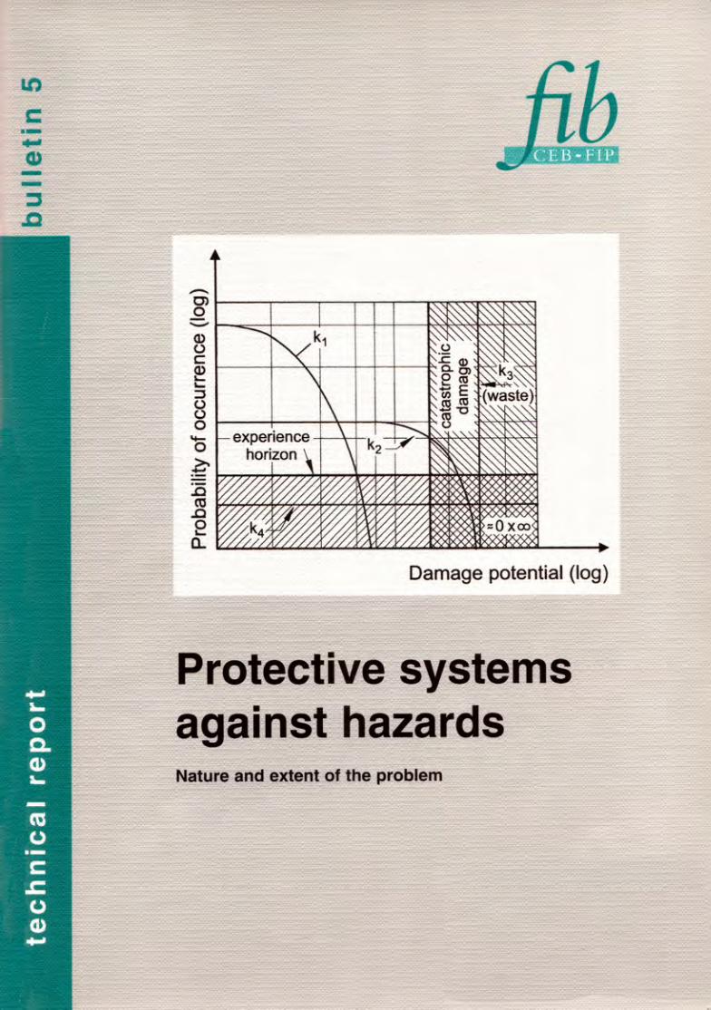
Risk spectra The foregoing remarks and objections can be explained with the risk spectra shown in Fig. 2.4 [4,11]. The risk spectrum K1 indicates well-defined risks associated with, for example, storage of some raw materials and well defined industrial processes. Spectrum K2 represents the risk adopted in some branches of the process industry, where catastrophic accidents have turned out to be possible. Examples are the Bho-pal accident in 1986 [24] and the Mexico City LPG-disaster in 1984 [25]. Spectrum K3 stands for activities of which the consequences in case of an accident are so high, or the probability even unpredictable, that it would not be justified to accept them. Examples of K3-risks are found in the waste management business, where either the long-term consequences in case of a failing containment are unpredictable. In order to cope with this type of problems "System Technology" has been introduced. Features of this system tech-nology will be discussed in section 2.5. Spectrum K4 represents a Low Probability/High Consequence Risk. In those cases the theoretical event probability is so low, that no statistical data is available to verify these figures. Core melt-down accidents in nuclear power stations are examples of these K4-events. In those cases we are extrapolating beyond our experience horizon. For activities or processes, of which the risks fall in the right bottom corner of Fig. 2.3, the results of quantitative risk analyses become very uncertain. In these cases control of consequences is indispensable. Minimising the theoretical risks would only be speculative!
Fig. 2.4 Risk spectra (after [11]) 2.3 Consequence Control The consequence control concept Unlike the risk concept, which is strongly probabilistic-oriented and focuses on limitation of the product of event probability and consequence, the consequence control concept is more deterministic-oriented and focuses primarily on the limitation of the consequences.
Probability of occurrence (log)
Damage potential (log)
experiencehorizon
(waste)k3
k4
k1
k2
˜̃ 0 x
cata
stro
phic
dam
age
Copyright fib, all rights reserved. This PDF copy of fib Bulletin 5 is intended for use and/or distribution only by National Member Groups of fib.

fib Bulletin 5: Protective systems against hazards 12
In this concept maximum credible actions, or loadings, are defined for which structural protective systems have to be designed deterministically, irrespective of the probability of occurrence of these loads. The maximum credible loads follow from well-considered accident scenario's. This concept is to be followed in all those cases where catastrophic consequences of an accident are conceivable. The finite energy concept A concept that, similarly to the consequence control concept, focuses on the control of consequence is the so called "Finite Energy Concept". Although not presented in the wording Finite Energy Concept, the basic principle of this approach has been explained by Eibl during the FIP-symposium in Budapest [7]. The idea behind the concept is that a product, whether it is identified as a raw material, an energy carrier or a waste, represents a finite amount of energy or a finite contaminating potential. The consequences of an accident with these products must, therefore, also be finite and can, in principle, be designed for with finite measures. Examples of this principle are the maximum fire duration of an LNG-fire, the maximum pressure in a nuclear containment in case of a major internal accident and the maximum blast overpressure caused by an explosion of a gas cloud of a certain volume. The maximum values of the actions are based on physical laws and have, in that sense, a deterministic character. 2.4 Safety-promoting methods Once a certain safety level is defined, either in terms of an acceptable risk or acceptable consequences, several methods are available to realise these target safety levels. Traditional safety promoting methods are shown on the reliability scale in Fig. 2.5. Active safety Active safety deals with mechanical and electrical equipment, installed with the intention to avoid the occurrence of serious accidents. Active safety also comprises the regulations of a plant in operation and training programs to ensure that all the employees act according to the prevailing instructions. For maintenance of many mechanical and electrical safety devices, operational tests and - if necessary - readjustments of them are to be carried out after fixed working periods. The level of active safety is en-dangered by adjustment aberration almost constantly. Furthermore it has been proved by experience that sometimes active safety devices have been put out of use in case they might affect the normal plant oper-ation. It is obvious that in those cases it is a lack of discipline and human error rather than malfunctioning of the active safety devices that has to be blamed. The active safety approach can be effective in all those cases where a clear understanding exists of things that can go wrong. It is well recognised, however, that major catastrophes are generally triggered by an unexpected or incredible chain of events. The Chernobyl accident, for example, resulted from a combi-nation of events of which the coincidence had been assumed unrealistic [15]. A coincidence of events which goes beyond our logic or imagination cannot be anticipated, since we don't have a format according to which we should act in order to prevent the occurrence of a chain of events of which the coincidence had never been considered before.
Copyright fib, all rights reserved. This PDF copy of fib Bulletin 5 is intended for use and/or distribution only by National Member Groups of fib.

2. Safety concepts
13
Fig. 2.5 Reliability scale (after [9]) Passive safety Passive safety refers to structural systems, which are able to cope with the effects of accidental actions in such a way that the consequences remain limited. For their functioning, passive safety systems rely predominantly on natural laws and are almost completely independent of human intervention. Examples are the well-known fire wall and concrete safety walls and safety tanks around storage tanks for hazardous products. Concrete structures, because of their robustness and massness, are very much suited to be designed as passive safety systems. Unlike active safety measures, there is hardly any chance for jeopardising the protective potential of a concrete structure due to human acts. Defects will evidence themselves directly after erection and can easily be repaired. Inherent safety Inherent safety refers to natural laws and to the plant lay-out. Elements of the inherent safety principle are found in the aforementioned Finite Energy Concept and are, in a way, also present in passive safety ele-ments. In principle, the idea of inherent safety is the best one to assure an appropriate safety level. An example of inherent safety is the absolute elimination (deterministically) of the probability that a pipe or vessel will burst due to internal overpressure by using non-pressurised transport and storage systems. In practice the implementation of inherent safety may meet considerable technical and operational constraints. Further-more, it is typical for large-scale plants, that even after being put into operation, there are many revisions in the planning of the plant. Corresponding to the complexity of these procedures, the probability of human errors is high and may jeopardise the safety of plants that were initially designed on the basis of the inherent safety principle. Defence-in-depth Defence-in-depth relates to a multi-barrier concept with a high degree of natural or man-made redundancy. The concept may comprise all types of afore mentioned safety elements. The defence-in-depth principle has been developed in order to achieve maximum safety of nuclear power plants. At present the principle is also adopted for non-nuclear risk-bearing activities, for example for LNG storage tanks located in the close vicinity of populated areas or airports and for other facilities with a high damage potential.
Active Safety Passive Safety
Range where concrete protective structures are required
Inherent Safety Defence-in-Depth
Increasing degree of:- Reliability- Consequence control
Copyright fib, all rights reserved. This PDF copy of fib Bulletin 5 is intended for use and/or distribution only by National Member Groups of fib.
fib Bulletin 5: Protective systems against hazards 14
2.5 System technology The concept "System Technology" it a new safety promoting concept, which can be used in those cases where traditional concepts are bound to fail. In those traditional concepts it is presumed that processes or activities which have to be safeguarded are well understood. This, however, is not always the case. In those cases system technology is considered a reasonable, if not the only alternative. The system technology concept is characterised by its system redundancy. The built-in system redundancy will enable people to intervene in processes which are not completely understood or uncertain at the onset of the period for which a certain protective measure has to fulfil its protective function. System technology is considered indispensable, for example, in case of storage of hazardous wastes, of which the chemical and biological composition as well as the possible reactions between waste and containment can not be predicted reliably. Examples and details of the system technology concept are discussed in view of the waste problem in the next chapters. System technology versus materials technology In the traditional safety philosophy emphasis is mainly on materials technology. If mechanical actions have to be designed for, one has to choose a material with certain strength. Designing for chemical attacks forces us to chose a building material with an adequate chemical resistance. In those cases the reliability and safety mainly depends on materials technology. With systems technology, on the contrary, emphasis is on the performance of the protective system as a whole. This includes materials technology, but is mainly characterised by the ability to guarantee adequate protection even in case of local, materials-oriented, failures of the system. Characteristics of system technology Characteristic features for a system technology-oriented design are • Inspectability • Controllability • Reparability • Renewability without interrupting operation. These four features are of great interest when dealing with storage of hazardous wastes. Storage systems for wastes of which the composition is not sufficiently known shall be so designed to allow regular inspection and control of the structure storing the waste. If these inspections reveal damage, repair and/or renewal of the structure should be possible. Repair and renewal should be possible without taking the system out of operation. Examples of how to realise this are presented in Chapter 5. Typical for the system technology concept is the anticipation on the occurrence of unpredictable events by providing well-considered built-in redundancy of the protective system. This is the best strategy for reliable control of the consequences. 2.6 Structural protective systems For control of consequences the use of passive safety components are most appropriate. A component is considered a part of a protective system. A component may consist of several elements, viz. beams, walls, etc. At present structural protective systems with a high built-in passive safety potential are judged the most reliable and also technically achievable solutions for adequate protection of the environment and for per-sonal safety. Particular features of those systems will be discussed in the following paragraphs.
Copyright fib, all rights reserved. This PDF copy of fib Bulletin 5 is intended for use and/or distribution only by National Member Groups of fib.
2. Safety concepts
15
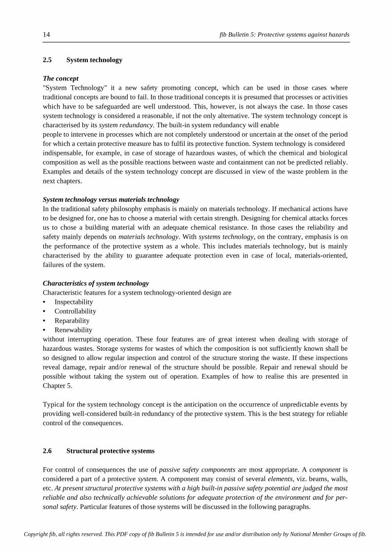
Function of structural protective systems Structural protective systems shall protect people and environment - the natural as well as the technological environment - against external and internal hazards (Fig. 2.6). External hazards are natural phenomena, like extreme climatic conditions, hurricanes and tornadoes, earthquakes, floods and lightning, as well as industry-related hazards, like gas cloud explosions, extreme thermal loads (fires and cryogenic temperature actions) and impact loads. Internal hazards are, for example, fires and explosions, which occur inside a (protected) facility due to malfunctioning of an industrial process or a structural element. Examples are a nuclear core melt-down, a BLEVE or a dynamic liquid impact in case of a sudden failure of a liquid re-taining inner tank. Besides technical malfunctioning also human errors may cause dangerous situations. A more detailed description of such hazards is presented in chapter 3. Protective systems shall be able to prevent or control contamination of soil and ground water, of open water and of the air, as far as possible. The required degree of protection depends on the consequences of uncontrolled releases of hazardous products to the environment. Control of consequences requires full inte-grity of the sys-tem under foreseeable actions and action combinations. For proper functioning a protective system shall exhibit at least four basic protective features: viz. load bearing, shielding (isolation), insulating, and retaining. 1. Load bearing - During normal operation a protective structure has to carry its own weight, all actions with the operation of the protected facility as well as and climate-induced actions. In many cases, however, the protective structure also fulfils an active load-bearing function in the operational stage, for example in case of a load-bearing tank wall for storage of hazardous liquids and control buildings. 2. Shielding and isolation - The shielding capacity of protective structures is generally expressed in terms of energy absorption capacity. Particularly in case of dynamic loads, like explosions, impact and earth-quakes, energy dissipation enhances the probability of the structure to survive. A special form of shielding is isolation, a form of protection used in a-seismic designs whereby sensitive parts of a structural system are partly physically separated from the agitated environment by isolators [36,37].
Fig. 2.6 Structural protective systems. Protection against external and internal hazards
impact
radiation
external hazards internal hazards
!p
firephysico-chemicalatacktornado
blast!p
net workcentrebulk storageof hazardouswastehigh riskactivities
Copyright fib, all rights reserved. This PDF copy of fib Bulletin 5 is intended for use and/or distribution only by National Member Groups of fib.
fib Bulletin 5: Protective systems against hazards 16
3. Insulating - A specific form of shielding is insulating. It refers to the protection against either radiation (fire) or cryogenic temperatures. A material with low thermal conductivity and high heat capacity is recommendable. 4. Retaining - Protective systems may be designed for storage of solids, liquids and gases. Particularly in case of storage of liquids and gases the container shall be liquid- and/or gastight. Whether any leakage from the container shall be prevented or some minor leakage is considered acceptable, will depend on the conse-quences of leakage. In case leakage of toxic gases is involved full tightness is a prerequisite. When flammable or explosive products are involved, accident scenarios are conceivable where minor leakage will not lead to escalation of the accident. In those cases minor leakage can be permitted and adequate tightness is sufficient. A more detailed classification of tightness criteria and design recommendation for tightness are presented in Part II of this series. 5. Structural and systems integrity - The afore-mentioned basic protective functions of structural protective systems can be considered as particular features of a structural system of which the integrity must be guaranteed under all foreseeable circumstances. Structural integrity can be accomplished by a well- considered structural design. With 'systems integrity' not only the structural design, but the consistency in performance of the protective system as a whole is meant. 2.7 Why concrete protective structures? Some specific features of concrete and concrete structures are of particular importance in view of designing structural protective systems for consequence control. A number of these features are listed below. a. Adaptability in shape and size - Structural protective systems are often considered as a disturbing factor in process engineering and for the layout of industrial facilities. In order to minimise the impact on the plant layout, structural protective systems shall be adaptable in shape and size. Protective structures in reinforced and/ or prestressed concrete, either in-situ or precast, exhibit this adaptability. It should be noticed that structural protective systems can also have, and mostly do have, a positive impact on the plant lay-out. Because of the protective properties of concrete structures industrial facilities can be built more compact without increasing the hazard potential. In this way land is used more economically and the environmental impact is minimised. The presence of protective systems may also have a positive effect on the safety distances between a facility and surrounding public buildings. b. Function separation - The hybrid character of reinforced and prestressed concrete allows the designer to carry through a high degree of function separation. The insulating and retaining function can be fulfilled mainly by the concrete, whereas the reinforcing and prestressing steel, in combination with the concrete, is mainly responsible for the load bearing and shielding function. c. Energy dissipation - Plain concrete itself is a brittle, non-ductile material. Properly designed reinforced and partially prestressed concrete structures, however, can behave in a ductile way and hence absorb substantial amounts of energy. As a result of the ductile behaviour maximum dynamic forces can be significantly reduced. This enhances the probability that a dynamically loaded structure will survive and can perform liquid tight. Adding fibres to the concrete mix significantly enhances the energy dissipation capacity of the concrete.
Copyright fib, all rights reserved. This PDF copy of fib Bulletin 5 is intended for use and/or distribution only by National Member Groups of fib.
2. Safety concepts
17
d. Zip-resistance Under certain special conditions steel storage tanks may fail in a particular failure mode, known as zipping. In a zip-failure a steel tank wall ruptures almost instantaneously over its full height and will be torn off from the bottom plate in whole or in part. The stored liquid will spread around in an uncontrolled way un-less a protective structure prevents this. An example of a zip-failure of a steel tank is presented in section 4.2. In properly designed and executed prestressed concrete structures this zip-failure mode will not occur. e. Availability - Even in case risk-bearing industrial activities are planned in remote areas, the raw materials for making structural protective structures of concrete will generally be available. f. Economics - Function separation as mentioned under b), makes it possible to "tailor" a protective structure so that an optimum between price and safety is achieved. For example, increased resistance against impact, fire and blast loads can relatively easily be obtained by increasing the thickness of the con-crete, whereas the amount of steel has to be increased only for ensuring that the amount of minimum reinforcement is installed. Since concrete is by far the cheapest component of the composite, the increase in costs for enhanced resistance against extreme loading conditions is relatively low. g. Environment friendly - Already today, but even more in the future, construction materials will be judged by their potential impact on the environment. In this respect concrete is a product that is relatively harmless and can, therefore, be used for structural protective systems without running the risk to create another envi-ronmental problem [16,38]. The recyclability of concrete structure further contributes to its environment friendliness. 2.8 Deterministic levels of protection Although the number of industrial accidents increases each year, statistical data on accidental actions is rather scanty. This holds particularly for catastrophic events and also in case of principally undefinable hazardous actions as they occur in the waste business. In those cases control of consequences should be in the focus of attention. The deterministic design approach is illustrated in Fig. 2.7 and in essence also in the flow chart in Fig. 2.2. In the design of structural protective systems the resistance R of the system should be sufficiently higher than the effects S caused by the actions. With regard to their statistical features R and S differ considerably. From a comparison of the action spectrum (Fig. 2.7, upper part) with the resistance spectrum R (Fig. 2.7, bottom part), it can be deduced that in most cases the resistance of concrete protective structures can be calculated in a deterministic way. For example, with the protective system RI minor impact loads can be resisted deterministically, but may fail to resist aircraft impact. Aircraft impact is covered deterministically with system RII. Low probability events: Definable actions The deterministic-oriented approach is of particular interest in cases where due to scarcity of statistical data the theoretical probability of occurrence of accidents can not be assessed reliably. In those cases emphasis should be on the assessment of the consequences of possible catastrophic accidents. In this approach esti-mates of the intensity of hazard actions are made on the basis of conservative assumptions as regards the magnitude and character of the actions (loads) and the possible chain of events that may be triggered by an initiating event.
Copyright fib, all rights reserved. This PDF copy of fib Bulletin 5 is intended for use and/or distribution only by National Member Groups of fib.
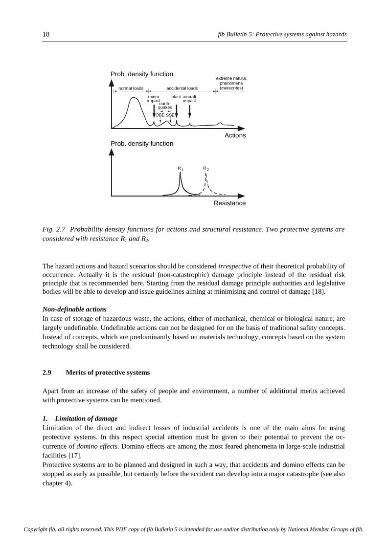
fib Bulletin 5: Protective systems against hazards 18
Fig. 2.7 Probability density functions for actions and structural resistance. Two protective systems are considered with resistance R1 and R2. The hazard actions and hazard scenarios should be considered irrespective of their theoretical probability of occurrence. Actually it is the residual (non-catastrophic) damage principle instead of the residual risk principle that is recommended here. Starting from the residual damage principle authorities and legislative bodies will be able to develop and issue guidelines aiming at minimising and control of damage [18]. Non-definable actions In case of storage of hazardous waste, the actions, either of mechanical, chemical or biological nature, are largely undefinable. Undefinable actions can not be designed for on the basis of traditional safety concepts. Instead of concepts, which are predominantly based on materials technology, concepts based on the system technology shall be considered. 2.9 Merits of protective systems Apart from an increase of the safety of people and environment, a number of additional merits achieved with protective systems can be mentioned. 1. Limitation of damage Limitation of the direct and indirect losses of industrial accidents is one of the main aims for using protective systems. In this respect special attention must be given to their potential to prevent the oc-currence of domino effects. Domino effects are among the most feared phenomena in large-scale industrial facilities [17]. Protective systems are to be planned and designed in such a way, that accidents and domino effects can be stopped as early as possible, but certainly before the accident can develop into a major catastrophe (see also chapter 4).
Prob. density function
Prob. density functionActions
Resistance
normal loads accidental loads
blast aircraftminorearth-
OBE SSE
impactimpactquakes
R R1 2
extreme naturalphenomena(meteorites)
Copyright fib, all rights reserved. This PDF copy of fib Bulletin 5 is intended for use and/or distribution only by National Member Groups of fib.

2. Safety concepts
19
2. Operationability and availability Enhancement of the level of protection of vital parts of an industrial facility, i.e. of production units, stands for a decrease of losses caused by process interruptions. When dealing with hazardous substances, en-hanced levels of protection will result in a reduction of the probability that ground water will be contami-nated by hazardous percolate, thus rendering ground water unfit for the use as drinking water. An eva-luation of the consequences of process interruption should be an essential part of the decision process as regards the adoption of concrete protective systems. 3. Profile of technique and technology Each industrial accident and each message about another contaminated area is stuff for a negative appraisal of technique and technology by society. The aim is not to justify every aspect of modern technique and technology, but because it is the responsibility of industrial and technical disciplines towards society to im-prove the quality and reliability of technique and technology that the FIP is contributing to the discussion on environmental issues. In this discussion the engineering discipline should point out how it, with its par-ticular expertise, can contribute to enhance safety and to protect the environment. To this end the adoption of structural protective systems, with a high potential to reduce the vulnerability of risk-bearing facilities, are judged indispensable. An enhancement of the acceptability and improvement of the image of technique and technology is then a result rather than the aim of the adoption of protective systems. 2.10 Summary Presently used safety concepts have revealed their inadequacy when catastrophic industrial disasters are to be dealt with, generally known as Low Probability/High Consequence Risks. This type of risks have to be considered in case actions are largely, or even principally undefinable, for example when dealing with haz-ardous wastes. In all those cases adequate protection can not be achieved by limitation of the risk, i.e. the product of event probability and consequences, but by limitation of the consequences, irrespective of the event probability. This leads to deterministic oriented design concepts. In these concepts passive safety is a key-word. Passive safety can be accomplished with structural elements, components or structures of reinforced or prestressed concrete. Passive safety element can also be part of a more comprehensive protective system. Those systems can not be characterised merely by the presence of passive safety elements, but also by their inspectability, controllability, reparability and renewability. These systems have been introduced here under the term "system technology". System technology is estimated to be one of the most promising approaches for ade-quate treatment and managing of hazardous waste with undefinable composition.
Copyright fib, all rights reserved. This PDF copy of fib Bulletin 5 is intended for use and/or distribution only by National Member Groups of fib.

3. Hazard actions
21
3 Hazard Actions 3.1 General The actions concrete protective systems have to be designed for, strongly depend on the particular conditions of the site and the facility and on the physical and chemical properties of substances involved in an accident. Because of the site- and facility-dependency of the actions it is difficult to specify them. For a number of hazard loads, however, like explosions, fires, impact and earthquakes, the most important par-ameters which determine the character and magnitude of these actions are known. The main parameters of hazard loads being known, simplified predictive models can be applied for parametric sensitivity studies. The results of these studies can be of great importance in the design stage of a project. Based on these stu-dies the weak points of a design can be found and the design can be improved. This chapter contains a short overview of hazard actions. A detailed description of these actions and of predictive engineering models of hazard actions are found in Part II of this series. Subsequently the following hazard loads and hazardous actions will be dealt with: • Explosions • Thermal actions (like industrial fires and cryogenic shock) • Impacts • Earthquakes • Tornado's, hurricanes • Chemical and biological action It must be born in mind that hazard actions generally do not occur on their own, but as a part of a comprehensive hazard scenario. Ignorance of the actual hazard scenario may result in an unbalanced design, either unsafe or too expensive. 3.2 Blast Origin Blast loads result from the ignition of explosive solid charges, dust-air and gas-air mixtures. Blast effects caused by conventional explosive charges will not be dealt with in this report. For an overview of dust explosions and how to deal with them, reference is made to [39]. Explosions caused by vapour cloud ignition are subdivided into Unconfined Vapour Cloud Explosions (UVCE) and Boiling Liquid Expanding Vapour Explosions (BLEVE). It is noticed that in most accidents where vapour clouds are involved, a certain degree of confinement of the vapour cloud has occurred. Unconfined Vapour Cloud Explosions Large industrial accidents, as in Flixborough (1974) and Fezin (1966) (ibid.[20]) and Beek (1976) [97], have demonstrated the devastating potential of vapour cloud explosions. Statistics convincingly show the need to consider these explosions carefully: in the period 1980-1985 approximately 400 incidents have been registered [40]. On ignition of a flammable vapour cloud two different modes of combustion can occur, viz. deflagration and detonation.
Copyright fib, all rights reserved. This PDF copy of fib Bulletin 5 is intended for use and/or distribution only by National Member Groups of fib.
fib Bulletin 5: Protective systems against hazards
22
a. Deflagration - On leakage of a liquid or gas a flammable fuel-air mixture can be formed. The most likely mode of combustion after ignition of an unconfined flammable vapour cloud is a deflagration [18,40-42]. A deflagration is a subsonic expansion wave, in which both the pressure and the density decrease across the wave front. The ignition energy for a deflagration is not more than a few tenths of a milli-Joule. This means that only a spark, but also the presence of hot surfaces, is sufficient to ignite the cloud. The flame velocity, the parameter that is of major importance in view of the generated overpressure, is of the order of meters per second. The associated overpressures are less than 1 kPa (0.01 bar). Under certain circumstances a slow starting combustion can develop into a blast wave with overpressures up to several tens of bars. The pre-sence of obstacles, i.e. partial confinement of the vapour cloud, is a major parameter in this respect. b. Detonation - A detonation is a supersonic, coupled reaction-zone shock wave complex that propagates at a constant speed of about 1,500 to 2,000 m/s through a uniform combustible mixture. Overpressures across the wave front may reach values up to about 15 bar. For a direct initiation of a detonation sometimes a few kilogram of a high explosive is needed [40]. This makes detonation of an unconfined vapour cloud very unlikely to occur. According to Geiger [18] smaller amounts of high explosives may also suffice to initiate the detonation of an unconfined vapour cloud. His data obviously refer to dense and homogeneous mixtures, a condition that almost never occurs in practice. The only known example of a detonation of an UVCE in practice is the explosion at Port Hudson, where a substantial part of a large unconfined propane-air cloud detonated [41]. Boiling Liquid Expanding Vapour Explosion A BLEVE, the acronym for Boiling Liquid Expanding Vapour Explosion, is a physical explosion, which occurs on failure of a steel pressure vessel. An external fire or an impact load can cause this failure. On sudden failure of a pressure vessel a large amount of stored energy is released instantaneously. The instan-taneous release of energy is accompanied by three damage-causing phenomena: • Formation of a blast wave • Launching of missiles, i.e. tank fragments (primary and secondary fragments) • If flammable, the formation of a fire ball causing intensive thermal radiation. Past accidents have revealed that BLEVE's can easily trigger domino effects, which may completely destroy large parts of a plant [9]. Many BLEVE's occurred in the Mexico-LPG disaster (1984). In that accident, in which almost 600 people died, about 50 tanks were destroyed in whole or in part [28]. Estimated direct losses amounted up to 150 billion dollars. Overpressures The overpressures yielded in a deflagrating vapour cloud will remain small unless the exploding cloud is substantially confined. Without substantial confinement peak overpressures are assumed not to exceed 0.3 bar [18]. From the evaluation of past industrial accidents it appears that in case of substantial confinement peak overpressures may reach up to 2 bar [18]. At present a small number of predictive methods is available for estimating the overpressure of gas could explosions numerically. The degree of confinement is considered explicitly in those models. An overview of them and examples how to use them for engineering purposes are dealt with in Part II of this series. Blast load specifications The complex nature of blast loads and the many factors that affect the parameter values of a blast loading, make it very difficult to specify these loads. For determination of the response of a structure on a blast loading the peak overpressure and the positive phase should be known. Several codes dealing with protective structures, however, only mention blast loads without specifying them in detail (Table 3.1).
Copyright fib, all rights reserved. This PDF copy of fib Bulletin 5 is intended for use and/or distribution only by National Member Groups of fib.
3. Hazard actions
23
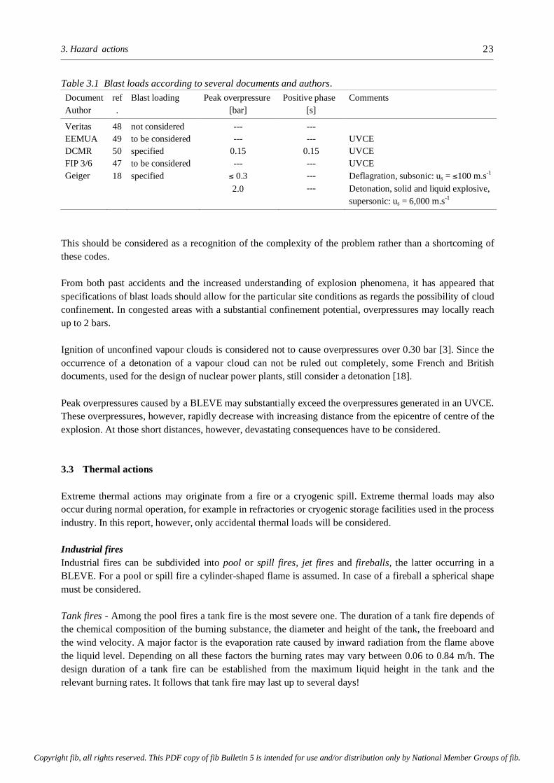
Table 3.1 Blast loads according to several documents and authors. Document Author
ref.
Blast loading Peak overpressure [bar]
Positive phase [s]
Comments
Veritas EEMUA DCMR FIP 3/6 Geiger
48 49 50 47 18
not considered to be considered specified to be considered specified
--- --- 0.15 --- ≤ 0.3 2.0
--- --- 0.15 --- --- ---
UVCE UVCE UVCE Deflagration, subsonic: us = ≤100 m.s-1
Detonation, solid and liquid explosive, supersonic: us = 6,000 m.s-1
This should be considered as a recognition of the complexity of the problem rather than a shortcoming of these codes. From both past accidents and the increased understanding of explosion phenomena, it has appeared that specifications of blast loads should allow for the particular site conditions as regards the possibility of cloud confinement. In congested areas with a substantial confinement potential, overpressures may locally reach up to 2 bars. Ignition of unconfined vapour clouds is considered not to cause overpressures over 0.30 bar [3]. Since the occurrence of a detonation of a vapour cloud can not be ruled out completely, some French and British documents, used for the design of nuclear power plants, still consider a detonation [18]. Peak overpressures caused by a BLEVE may substantially exceed the overpressures generated in an UVCE. These overpressures, however, rapidly decrease with increasing distance from the epicentre of centre of the explosion. At those short distances, however, devastating consequences have to be considered. 3.3 Thermal actions Extreme thermal actions may originate from a fire or a cryogenic spill. Extreme thermal loads may also occur during normal operation, for example in refractories or cryogenic storage facilities used in the process industry. In this report, however, only accidental thermal loads will be considered. Industrial fires Industrial fires can be subdivided into pool or spill fires, jet fires and fireballs, the latter occurring in a BLEVE. For a pool or spill fire a cylinder-shaped flame is assumed. In case of a fireball a spherical shape must be considered. Tank fires - Among the pool fires a tank fire is the most severe one. The duration of a tank fire depends of the chemical composition of the burning substance, the diameter and height of the tank, the freeboard and the wind velocity. A major factor is the evaporation rate caused by inward radiation from the flame above the liquid level. Depending on all these factors the burning rates may vary between 0.06 to 0.84 m/h. The design duration of a tank fire can be established from the maximum liquid height in the tank and the relevant burning rates. It follows that tank fire may last up to several days!
Copyright fib, all rights reserved. This PDF copy of fib Bulletin 5 is intended for use and/or distribution only by National Member Groups of fib.
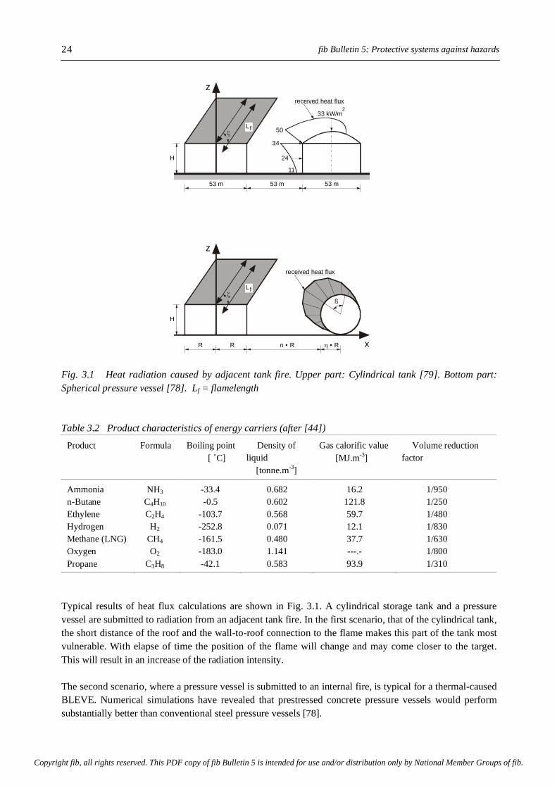
fib Bulletin 5: Protective systems against hazards
24
Fig. 3.1 Heat radiation caused by adjacent tank fire. Upper part: Cylindrical tank [79]. Bottom part: Spherical pressure vessel [78]. Lf = flamelength Table 3.2 Product characteristics of energy carriers (after [44])
Product Formula Boiling point [ ˚C]
Density of liquid [tonne.m-3]
Gas calorific value [MJ.m-3]
Volume reduction factor
Ammonia n-Butane Ethylene Hydrogen Methane (LNG) Oxygen Propane
NH3 C4H10 C2H4 H2 CH4 O2 C3H8
-33.4 -0.5
-103.7 -252.8 -161.5 -183.0 -42.1
0.682 0.602 0.568 0.071 0.480 1.141 0.583
16.2 121.8 59.7 12.1 37.7 ---.- 93.9
1/950 1/250 1/480 1/830 1/630 1/800 1/310
Typical results of heat flux calculations are shown in Fig. 3.1. A cylindrical storage tank and a pressure vessel are submitted to radiation from an adjacent tank fire. In the first scenario, that of the cylindrical tank, the short distance of the roof and the wall-to-roof connection to the flame makes this part of the tank most vulnerable. With elapse of time the position of the flame will change and may come closer to the target. This will result in an increase of the radiation intensity. The second scenario, where a pressure vessel is submitted to an internal fire, is typical for a thermal-caused BLEVE. Numerical simulations have revealed that prestressed concrete pressure vessels would perform substantially better than conventional steel pressure vessels [78].
z
z
x
53 m
R R
53 m
n R• ! R•
53 m
11
24
34
50
33 kW/m2
received heat flux
received heat flux
Lf
Lf
H
H
"
"ß
Copyright fib, all rights reserved. This PDF copy of fib Bulletin 5 is intended for use and/or distribution only by National Member Groups of fib.
3. Hazard actions
25
Ball fires - The burning time of a BLEVE depends on the amount of flammable substance involved in the ball fire. The duration is generally not more than a few to several tens of seconds. In [25] an experience-based model is presented with which the burning time of a ball fire can be determined numerically. Cryogenic temperatures In the process industry products are used and stored at temperatures far below zero. The advantage of cooling down to their boiling point is the huge volume reduction that is achieved. This makes it attractive for storing at those low, or cryogenic, temperatures. For some products the boiling temperatures as well as their volume reduction factor are listed in Table 3.2. Concrete structures used in storage systems for cryogenic liquids may be submitted to these extremely low temperatures, either during normal operation or incidentally. The cryogenic loads one can distinguish between overall cooling and cold spot problems. Overall cooling - Overall cooling of a protective structure may occur due to failure of the inner tank of a cryogenic storage system. If a small defect of the inner tank is the cause of leakage, the protective outer tank will be filled and cooled gradually. At the location of the liquid level substantial temperature gradients occur in the vertical direction of the wall. Large temperature gradients have to be considered also over the thickness of the wall. Cold spot - Due to an accidental leak of liquefied gases a protective structure may be subjected to local cooling. Depending on the temperature of the leaking substance, large strains will be exerted. When excee-ding the strain capacity of the concrete, membrane cracks may occur. In several documents dealing with cryogenic storage a cold spot loading has been specified. The size of the cold spot is generally chosen arbitrarily, for example 2 x 5 m. It is noticed that, in view of the design for cold spot, it is not indifferent what size and location of the cold spot has been specified. Moreover, it should be indicated whether a cold spot loading is a final situation or just a transient stage in a scenario which might develop into a complete failure of the inner tank and cooling of the whole structure. It should be noticed that the thermal properties of concrete are temperature dependent. The lower the temperature, the more rapid a temperature front penetrates into a concrete barrier. Examples of hazard scen-arios and temperature distributions in concrete barriers are discussed in more detail in Parts II and III of this series. 3.4 Impacts Classification of impact Together with fire actions, impacts are the most feared accidental actions, which may occur in industrial accidents. Impact loads may originate from explosions, natural phenomena, industrial accidents, sabotage and airplane crashes. A classification of impact loads according to their origin in shown in Fig. 3.2. An impact load is characterised by the following parameters: • Velocity of the missile • Mass of the missile • Impact area • Deformability of the missile • Noze-shape factor
Copyright fib, all rights reserved. This PDF copy of fib Bulletin 5 is intended for use and/or distribution only by National Member Groups of fib.

fib Bulletin 5: Protective systems against hazards
26
In many actual situations it is difficult to define the impact parameters accurately. For this reason several codes dealing with design recommendations for protective structures do not give fixed values for impact loads (e.g. [47-50]). Examples of specified impact loads are presented in Table 3.3. Blast-generated impact loads - Evaluations of blast accidents have revealed, that impact masses may range from 10,000 to 70,000 kg with impact velocities between 60 to 150 m/s (Table 3.4). In these cases BLEVEs were the main cause of these severe impacts. In most cases it was very hard to define the size of the impact area. These observed impact characteristics substantially deviate from those found in some codes. Turbine-generated impact loads - The impact velocity of a turbine generated missile - a part of a failing rotating device - can relativity easily be calculated from the rotation velocity of the turbine. Guidelines for turbine generated missiles used in the design of protective structures for nuclear power plants are given by the ASCE [70] and have been summarised in [54].
Fig. 3.2 Impact loads, classified according to their origin [54] Table 3.3 Impact actions specified in currently used codes
Document ref. Type of missile Mass [kg]
Velocity m.s-1
Impact area [m] (diameter)
FIP 3/6 Bureau Veritas EEMUA DCMR
47 48 49 50
not specified not specified
valve valve
--- --- --- 200
--- --- 44 40
--- --- 0.10 ---
aircraft
source
tornado explosion
secondaryfragments
turbinegenerated
missile
primaryfragments
aircraftfuselage
equalsize
unequalsize
uncontrained contrained
car acc.railway acc.
valves etc.
aircraftengine
plant accidents sabotage
peace timewar time
Copyright fib, all rights reserved. This PDF copy of fib Bulletin 5 is intended for use and/or distribution only by National Member Groups of fib.

3. Hazard actions
27
Corrosion or fatigue generated impacts - Failure of devices which operate under pressure may cause parts of these devices to be launched and hit adjacent parts of a structure. Examples are valve covers, parts of piping, etc. Sabotage - It is generally considered not practical to design protective structures for a direct impact by large weapons [51]. Even with small weapons, which can be handled by one person, substantial damage can be brought about. Steel thickness up to 500 mm and concrete thicknesses up to 1,300 mm are perforable by missiles launched with these hand weapons. For required wall thicknesses to avoid perforation by different types of weapon, reference is made to [52]. With the aim to reduce the vulnerability for sabotage it has been suggested to built protective structures underground [53] (see Chapter 5). Zipping - A special type of impact, viz. a liquid impact, associated with the sudden failure of a steel storage tank, is zipping. In a zip-failure the wall of a steel tank tears open over the full height of the tank in a fraction of a second. The steel tank is then pushed in the direction opposite of the crack and may hit and da-mage surrounding structures. This failure mode has been a point of much concern for cryogenic storage tanks. Zip-failures, which have occurred in the past, have demonstrated devastating effects. An example will be discussed in more detail in chapter 4. Aircraft and helicopter impact In the period between 1954 and 1983 about 5,000 airliners crashed. In this figure crashes in the former USSR and China are not included. From the number of crashes per year a probability of an aircraft impact results of about 10-6/10,000 m2.y-1. Assuming that 1% of the country is built-up area, the probability that a crashing aircraft hits a building is about 10-8 y-1. Although this is only a small probability, it is known by experience that planes crashing do destroy buildings regularly. A crashing Boeing 747 destroyed a multi-storey apartment building near Amsterdam in 1992. In the same week a crashing plane destroyed a private house in the United States. In 1988 an F-16 crashed at 15 kilometre from a nuclear power plant in Germany. In the same year a Mirage F-1 crashed 1.5 kilometre from the nuclear power station in Landshut, also in Germany. These events may act as warning shots, teaching us that things that can go wrong do go wrong, sooner or later. Aircraft impact, therefore, should be considered as a realistic load case when dealing with High Consequence Risks. For nuclear power plants designing for aircraft impacts should be man-datory (not in all countries!). According to [48] the possibility of aircraft impact must be considered for storage systems for liquefied gases. Table 3.4 Impact characteristics, observed in past accidents
Location Type of missile Mass [kg]
Velocity [m/s]
Impact area [m] (diameter)
Romeo Ville (1984) Crescent City Mexico City (1984) Feyzin (1966) Texas City (1978)
Tank fragment, 500 m high, 3,000 m from epicentre Tank car fragment at 50 to 100 m from epicentre Tank fragments at 400 m Shell fragments, 70 tons at 300 m from epicentre Fragments over 230 m.
--- >10,460 13,000 70,000 ---
100 - 170 85 60 - 150 --- ---
--- --- 2.0 --- ---
Copyright fib, all rights reserved. This PDF copy of fib Bulletin 5 is intended for use and/or distribution only by National Member Groups of fib.

fib Bulletin 5: Protective systems against hazards
28
Like other impact loads, an aircraft impact is defined by the mass, velocity, impact area and deformability of the aircraft. For design purposes load-time diagrams have been defined. Fig. 3.3 shows a design curve for a load-time diagram of an F4-Phantom. In this figure a measured load-time curve is shown as well. Al-though there are difference between the two curves, it is obvious that the design curve approximates the real load case fairly well.
Fig. 3.3 Load-time diagram for aircraft impact (after [54])
3.5 Earthquakes Earthquakes can be characterised by horizontal and vertical ground motions. The vertical accelerations are usually a significant ratio (e.g. 2/3 [48,55]) of the horizontal accelerations. The design spectrum that has to be considered in a particular area and a particular facility must be specified by specialists. For the response analysis it is important that data on soil damping are available. Depending on the structure of the sub-grade and the local geological environment soil damping may reach up to 50%. This is substantially higher than structural material damping [49]. It has been proposed that a seismic analysis of protective systems should comprise two design earthquakes, each with a different probability of occurrence. 1. Operating Basis Earthquake (OBE) An operating basis earthquake is suggested to have a 10% probability of being exceeded during the structures lifetime. Under this loading the structure must remain in operation without interruption. Availability and operationability of the structure are the main aims here. 2. Safe Shutdown Earthquake (SSE) When submitted to this earthquake some damage is accepted, but the structure should not collapse nor should it impose serious consequential hazards (Limit State of Integrity). For the SSE a 1% probability of being exceeded during the structures lifetime has been suggested [49]. Whether this 1% probability is an acceptable limit will depend on the consequences in case the SSE would be exceeded and the structure would collapse. With the aim to allow a more differentiated judgement of storage systems for cryogenic storage of hazardous products which are submitted to a SSE, it has been suggested to split up the SSE into two levels, viz. SSE-1 and SSE-2 [55]. In a SSE-1 the inner tank must remain leak proof. After inspection and prob-
Impact force [MN]200
160
120
80
40
0
Time [ms]0 20 40 60 80 100
design load
full scale - test
Copyright fib, all rights reserved. This PDF copy of fib Bulletin 5 is intended for use and/or distribution only by National Member Groups of fib.
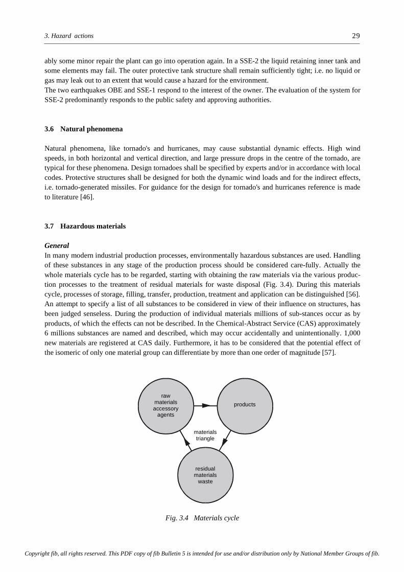
3. Hazard actions
29
ably some minor repair the plant can go into operation again. In a SSE-2 the liquid retaining inner tank and some elements may fail. The outer protective tank structure shall remain sufficiently tight; i.e. no liquid or gas may leak out to an extent that would cause a hazard for the environment. The two earthquakes OBE and SSE-1 respond to the interest of the owner. The evaluation of the system for SSE-2 predominantly responds to the public safety and approving authorities. 3.6 Natural phenomena Natural phenomena, like tornado's and hurricanes, may cause substantial dynamic effects. High wind speeds, in both horizontal and vertical direction, and large pressure drops in the centre of the tornado, are typical for these phenomena. Design tornadoes shall be specified by experts and/or in accordance with local codes. Protective structures shall be designed for both the dynamic wind loads and for the indirect effects, i.e. tornado-generated missiles. For guidance for the design for tornado's and hurricanes reference is made to literature [46]. 3.7 Hazardous materials General In many modern industrial production processes, environmentally hazardous substances are used. Handling of these substances in any stage of the production process should be considered care-fully. Actually the whole materials cycle has to be regarded, starting with obtaining the raw materials via the various produc-tion processes to the treatment of residual materials for waste disposal (Fig. 3.4). During this materials cycle, processes of storage, filling, transfer, production, treatment and application can be distinguished [56]. An attempt to specify a list of all substances to be considered in view of their influence on structures, has been judged senseless. During the production of individual materials millions of sub-stances occur as by products, of which the effects can not be described. In the Chemical-Abstract Service (CAS) approximately 6 millions substances are named and described, which may occur accidentally and unintentionally. 1,000 new materials are registered at CAS daily. Furthermore, it has to be considered that the potential effect of the isomeric of only one material group can differentiate by more than one order of magnitude [57].
Fig. 3.4 Materials cycle
rawmaterialsaccessory
agents
products
materialstriangle
residualmaterials
waste
Copyright fib, all rights reserved. This PDF copy of fib Bulletin 5 is intended for use and/or distribution only by National Member Groups of fib.
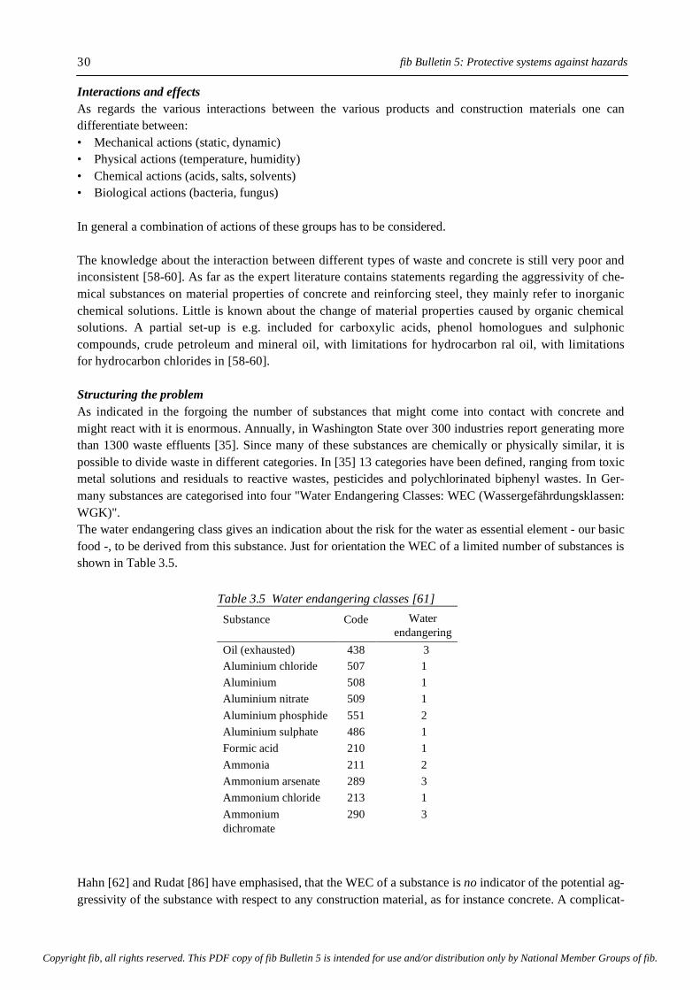
fib Bulletin 5: Protective systems against hazards
30
Interactions and effects As regards the various interactions between the various products and construction materials one can differentiate between: • Mechanical actions (static, dynamic) • Physical actions (temperature, humidity) • Chemical actions (acids, salts, solvents) • Biological actions (bacteria, fungus) In general a combination of actions of these groups has to be considered. The knowledge about the interaction between different types of waste and concrete is still very poor and inconsistent [58-60]. As far as the expert literature contains statements regarding the aggressivity of che-mical substances on material properties of concrete and reinforcing steel, they mainly refer to inorganic chemical solutions. Little is known about the change of material properties caused by organic chemical solutions. A partial set-up is e.g. included for carboxylic acids, phenol homologues and sulphonic compounds, crude petroleum and mineral oil, with limitations for hydrocarbon ral oil, with limitations for hydrocarbon chlorides in [58-60]. Structuring the problem As indicated in the forgoing the number of substances that might come into contact with concrete and might react with it is enormous. Annually, in Washington State over 300 industries report generating more than 1300 waste effluents [35]. Since many of these substances are chemically or physically similar, it is possible to divide waste in different categories. In [35] 13 categories have been defined, ranging from toxic metal solutions and residuals to reactive wastes, pesticides and polychlorinated biphenyl wastes. In Ger-many substances are categorised into four "Water Endangering Classes: WEC (Wassergefährdungsklassen: WGK)". The water endangering class gives an indication about the risk for the water as essential element - our basic food -, to be derived from this substance. Just for orientation the WEC of a limited number of substances is shown in Table 3.5. Hahn [62] and Rudat [86] have emphasised, that the WEC of a substance is no indicator of the potential ag-gressivity of the substance with respect to any construction material, as for instance concrete. A complicat-
Table 3.5 Water endangering classes [61] Substance
Code
Water endangering
Class class (WEC)
Oil (exhausted)
438
3 Aluminium chloride
507
1 Aluminium
gydroxychloride
508
1 Aluminium nitrate
509
1 Aluminium phosphide
551
2 Aluminium sulphate
486
1 Formic acid
210
1 Ammonia
211
2 Ammonium arsenate
289
3 Ammonium chloride
213
1 Ammonium
dichromate
290
3
Copyright fib, all rights reserved. This PDF copy of fib Bulletin 5 is intended for use and/or distribution only by National Member Groups of fib.
3. Hazard actions
31
ing factor in this respect is that even if the aggressive potential of a single substance would be known, the aggressive potential of a cocktail of substances is still unknown. Once the aggressive potential of a cocktail of substances is known, a subsequent question is whether this cocktail can be considered representative for the largely undefined mix of substances as found in different types of waste. In this respect one should also bear in mind that most of these tests were short-term tests. Time effects, as we know from the practice, can have a significant influence on the real behaviour of a material. If the interactions of the individual substances, or substance groups, with different (building) materials are known, it would still be unjustified to infer from this that also the interactions of mixtures of these substances with building materials are known As regards this topic an expert's view says [57,62,63]: "The influences of substances on materials and on the environment are in principle not predictable as: • During the chemical material production practically unlimited large numbers of by- products
will also arise through by-reactions • The effects of only a fraction of all these products can be analysed; • In tests only a very small percentage of he individual effects of substances, their synergisms and
metabolisms, can be examined". Another aspect, which cannot be neglected when defining the potential chemical and biological actions, is the relative uncertainty about the future product range of an owner and the associated uncertainty of the type of chemical/ biological actions. An owner can state what his product range is likely to be in the next few years, but he cannot precisely state what he will produce after 5 or 10 years! Due to the fast technical and technological developments there is a demand for short-term product rearrangements. In practice this means that an owner has often to decide whether he shall dismount a 5 year old concrete storage structure just because he has changed his product range and needs storage facilities which may need more stringent resistance properties, upgrade the old storage facility may be by providing the concrete with suitable protective layers. It is known that such improvements happen today. However, this can neither satisfy the client nor the construction industry, which in general design the lifetime of their structures for a longer time. In conclusion: In the foregoing the awareness should have been wakened, that the present problematic of environmentally hazardous substances and their actions on structures can hardly be solved with merely (construction) materials technology. With the traditional materials technology solutions it is presupposed that reliable storage of hazardous materials is possible by a proper choice of the building material of which a storage structure is built. A proper choice of the building material, however, is in essence only possible if the "action side" of the problem can be defined properly. This, however, is not always the case, as will be shown in the next sections. Waste material Waste contains various substances which are left behind during the production process and which no one can, or will, use any longer or of which its owner wants to get rid-off. Some of these wastes can be recycled relatively easily, but some can not. Moreover, recycling does not always make sense from the economical and ecological point of view. Diagrammatically this is shown in Fig. 3.5 [86].
Copyright fib, all rights reserved. This PDF copy of fib Bulletin 5 is intended for use and/or distribution only by National Member Groups of fib.

fib Bulletin 5: Protective systems against hazards
32
Fig. 3.5 Valuable materials cycle (left) and waste materials cycle (right) as part of the materials triangle [86]
In untreated waste all possible substances can be found in totally unknown composition. The composition and the associated potential aggressivity of the waste being unknown, the question what type of material and structure shall be chosen for encapsulating the waste material is a very difficult one. Materials, which may be considered, either individually or in combination with other materials, are all kinds of mineral and plastic or metallic sealing layers. This explains the still continuing efforts to try to investigate the influences of the "waste as-such" on the encapsulating materials. That such intentions are bound to fail can be inferred from the work of Hahn [57,62, 63]. The foregoing leads to the conclusion that a comprehensive analysis of the interaction of concrete with any organic waste material is practically impossible. The glycol scandal in Austria - concerning the wine - may serve as example that analyticians can only find what they are looking for. It is completely the same with the analysis of the interaction between waste and any building material. This led to a serious and far-rea-ching conclusion [57]: "The compositions of untreated wastes are - with regard to the environmentally relevant sub-stance portions - generally unknown. This will always be like that!" When summarising the knowledge gained from the previous considerations, the following statements can be made: • A comprehensive analysis of untreated waste is impossible. • The usual way of storage of mixed wastes leads to interactions with the encapsulation structure, which
cannot be predicted. • A sealing material, which is resistant against all kind of substances of the waste, does not exist and will
not exist. • There is no sealing material that permanently prevents the escape of contaminants into the ground or
ground water. • Actually no accepted limit or guide values of emission exist which define the quantity of contaminants
that can still be tolerated as environmentally acceptable if they might escape into the ground.
valuablematerials
cycle
materialstriangle
inert orenviron-mentallyneutral
multibarrierconcept
dumpdeposit
undergrounddump
wastetreatment
plant
residualmate-rials
waste
non-recyc-lablewaste
rawmaterialsaccessory
agents
interimstorage
interimstorage
treatment
treatment
secon-dary raw
mate-rials
recycling
T=!
Copyright fib, all rights reserved. This PDF copy of fib Bulletin 5 is intended for use and/or distribution only by National Member Groups of fib.

3. Hazard actions
33
For all these reasons the waste management has to go a different way. Examples of how to cope with this kind of problems will be discussed in next chapters of this report. Most reliable in this respect is the previously mentioned "systems technology". An approach considering things more politically than technically is partly recognised and legally formu-lated in [64-66,67]. The idea behind this new approach is to treat hazardous wastes in such a manner that their attacks on the containment and the environment become more or less definable again. This is to stay with the well-acquainted materials technology. References to the effect that this can be done successfully and long lasting, however, are still missing.
Copyright fib, all rights reserved. This PDF copy of fib Bulletin 5 is intended for use and/or distribution only by National Member Groups of fib.
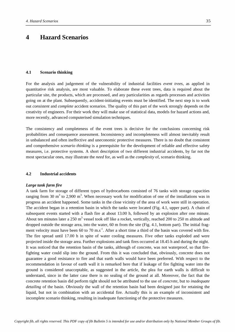
4. Hazard Scenarios 35 4 Hazard Scenarios 4.1 Scenario thinking For the analysis and judgement of the vulnerability of industrial facilities event trees, as applied in quantitative risk analysis, are most valuable. To elaborate these event trees, data is required about the particular site, the products, which are processed, and any particularities as regards processes and activities going on at the plant. Subsequently, accident-initiating events must be identified. The next step is to work out consistent and complete accident scenarios. The quality of this part of the work strongly depends on the creativity of engineers. For their work they will make use of statistical data, models for hazard actions and, more recently, advanced computerised simulation techniques. The consistency and completeness of the event trees is decisive for the conclusions concerning risk probabilities and consequence assessment. Inconsistency and incompleteness will almost inevitably result in unbalanced and often ineffective and uneconomic protective measures. There is no doubt that consistent and comprehensive scenario thinking is a prerequisite for the development of reliable and effective safety measures, i.e. protective systems. A short description of two different industrial accidents, by far not the most spectacular ones, may illustrate the need for, as well as the complexity of, scenario thinking. 4.2 Industrial accidents Large tank farm fire A tank farm for storage of different types of hydrocarbons consisted of 76 tanks with storage capacities ranging from 30 m3 to 2,900 m3. When necessary work for modification of one of the installations was in progress an accident happened. Some tanks in the close vicinity of the area of work were still in operation. The accident began in a retention basin in which the tanks were located (Fig. 4.1, upper part). A chain of subsequent events started with a flash fire at about 13.00 h, followed by an explosion after one minute. About ten minutes later a 250 m3 vessel took off like a rocket, vertically, reached 200 to 250 m altitude and dropped outside the storage area, into the water, 60 m from the site (Fig. 4.1, bottom part). The initial frag-ment velocity must have been 60 to 70 m.s-1. After a short time a third of the basin was covered with fire. The fire spread until 17.00 h in spite of water cooling measures. Five other tanks exploded and were projected inside the storage area. Further explosions and tank fires occurred at 18.45 h and during the night. It was noticed that the retention basin of the tanks, although of concrete, was not waterproof, so that fire-fighting water could slip into the ground. From this it was concluded that, obviously, concrete does not guarantee a good resistance to fire and that earth walls would have been preferred. With respect to the recommendation in favour of earth wall it is remarked here that if leakage of fire fighting water into the ground is considered unacceptable, as suggested in the article, the plea for earth walls is difficult to understand, since in the latter case there is no sealing of the ground at all. Moreover, the fact that the concrete retention basin did perform tight should not be attributed to the use of concrete, but to inadequate detailing of the basin. Obviously the wall of the retention basin had been designed just for retaining the liquid, but not in combination with an accidental fire. Actually this is an example of inconsistent and incomplete scenario thinking, resulting in inadequate functioning of the protective measures.
Copyright fib, all rights reserved. This PDF copy of fib Bulletin 5 is intended for use and/or distribution only by National Member Groups of fib.
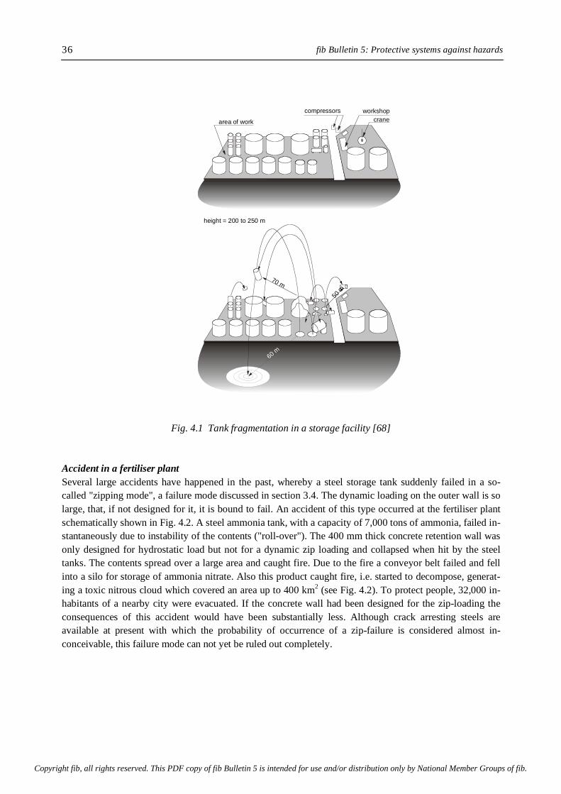
fib Bulletin 5: Protective systems against hazards 36
Fig. 4.1 Tank fragmentation in a storage facility [68] Accident in a fertiliser plant Several large accidents have happened in the past, whereby a steel storage tank suddenly failed in a so-called "zipping mode", a failure mode discussed in section 3.4. The dynamic loading on the outer wall is so large, that, if not designed for it, it is bound to fail. An accident of this type occurred at the fertiliser plant schematically shown in Fig. 4.2. A steel ammonia tank, with a capacity of 7,000 tons of ammonia, failed in-stantaneously due to instability of the contents ("roll-over"). The 400 mm thick concrete retention wall was only designed for hydrostatic load but not for a dynamic zip loading and collapsed when hit by the steel tanks. The contents spread over a large area and caught fire. Due to the fire a conveyor belt failed and fell into a silo for storage of ammonia nitrate. Also this product caught fire, i.e. started to decompose, generat-ing a toxic nitrous cloud which covered an area up to 400 km2 (see Fig. 4.2). To protect people, 32,000 in-habitants of a nearby city were evacuated. If the concrete wall had been designed for the zip-loading the consequences of this accident would have been substantially less. Although crack arresting steels are available at present with which the probability of occurrence of a zip-failure is considered almost in-conceivable, this failure mode can not yet be ruled out completely.
compressors workshopcranearea of work
height = 200 to 250 m
70 m
50 m
60 m
Copyright fib, all rights reserved. This PDF copy of fib Bulletin 5 is intended for use and/or distribution only by National Member Groups of fib.
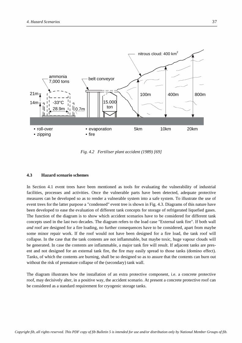
4. Hazard Scenarios 37
Fig. 4.2 Fertiliser plant accident (1989) [69] 4.3 Hazard scenario schemes In Section 4.1 event trees have been mentioned as tools for evaluating the vulnerability of industrial facilities, processes and activities. Once the vulnerable parts have been detected, adequate protective measures can be developed so as to render a vulnerable system into a safe system. To illustrate the use of event trees for the latter purpose a "condensed" event tree is shown in Fig. 4.3. Diagrams of this nature have been developed to ease the evaluation of different tank concepts for storage of refrigerated liquefied gases. The function of the diagram is to show which accident scenarios have to be considered for different tank concepts used in the last two decades. The diagram refers to the load case "External tank fire". If both wall and roof are designed for a fire loading, no further consequences have to be considered, apart from maybe some minor repair work. If the roof would not have been designed for a fire load, the tank roof will collapse. In the case that the tank contents are not inflammable, but maybe toxic, huge vapour clouds will be generated. In case the contents are inflammable, a major tank fire will result. If adjacent tanks are pres-ent and not designed for an external tank fire, the fire may easily spread to those tanks (domino effect). Tanks, of which the contents are burning, shall be so designed so as to assure that the contents can burn out without the risk of premature collapse of the (secondary) tank wall. The diagram illustrates how the installation of an extra protective component, i.e. a concrete protective roof, may decisively alter, in a positive way, the accident scenario. At present a concrete protective roof can be considered as a standard requirement for cryogenic storage tanks.
nitrous cloud: 400 km?
belt conveyor
0.7m
ammonia7,000 tons
14m
• roll-over• zipping
• evaporation• fire
28.9m-33°C
21m
15.000ton
100m
5km 10km 20km
400m 800m
nitrous cloud: 400 km2
Copyright fib, all rights reserved. This PDF copy of fib Bulletin 5 is intended for use and/or distribution only by National Member Groups of fib.
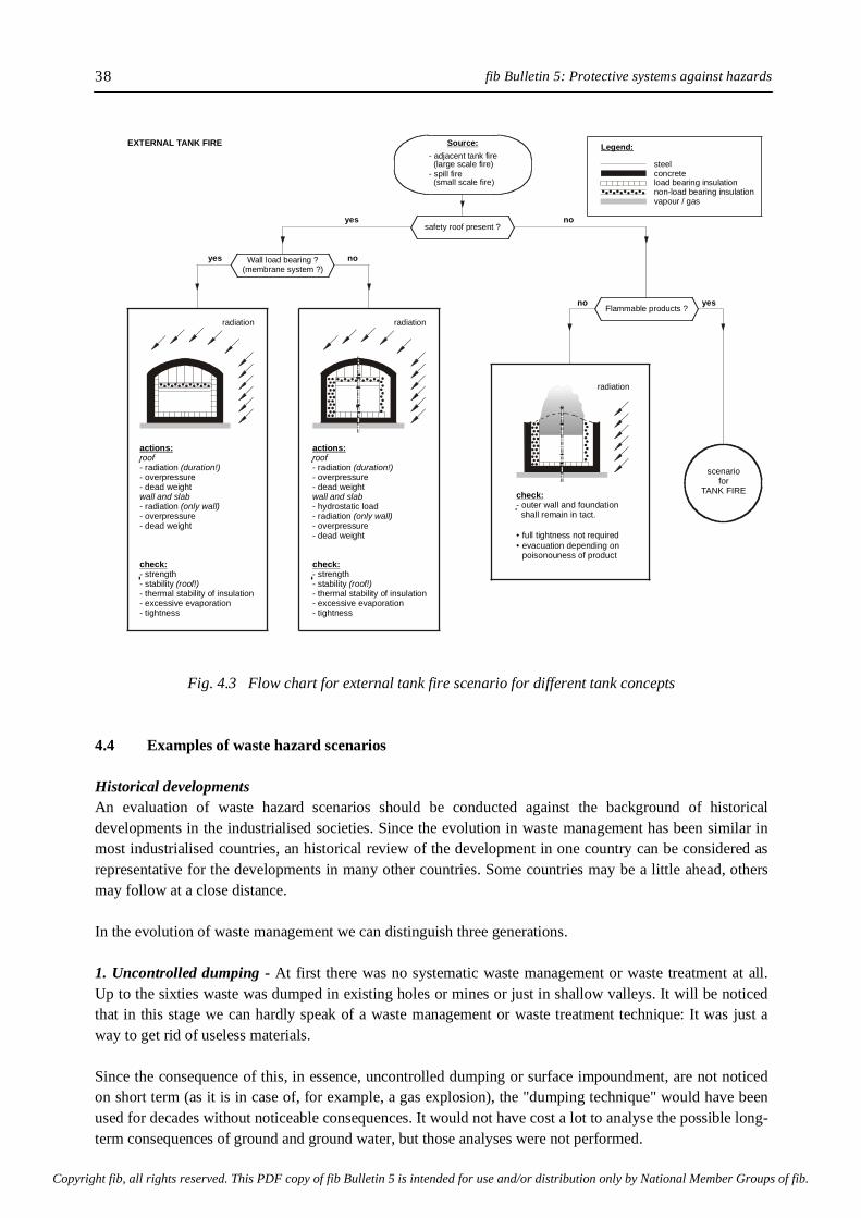
fib Bulletin 5: Protective systems against hazards 38
Fig. 4.3 Flow chart for external tank fire scenario for different tank concepts
4.4 Examples of waste hazard scenarios Historical developments An evaluation of waste hazard scenarios should be conducted against the background of historical developments in the industrialised societies. Since the evolution in waste management has been similar in most industrialised countries, an historical review of the development in one country can be considered as representative for the developments in many other countries. Some countries may be a little ahead, others may follow at a close distance. In the evolution of waste management we can distinguish three generations. 1. Uncontrolled dumping - At first there was no systematic waste management or waste treatment at all. Up to the sixties waste was dumped in existing holes or mines or just in shallow valleys. It will be noticed that in this stage we can hardly speak of a waste management or waste treatment technique: It was just a way to get rid of useless materials. Since the consequence of this, in essence, uncontrolled dumping or surface impoundment, are not noticed on short term (as it is in case of, for example, a gas explosion), the "dumping technique" would have been used for decades without noticeable consequences. It would not have cost a lot to analyse the possible long-term consequences of ground and ground water, but those analyses were not performed.
- radiation - overpressure- dead weight
actions:roof
(duration!)
wall and slab- radiation - overpressure- dead weight
- strength- stability - thermal stability of insulation- excessive evaporation- tightness
(only wall)
(roof!)
check:
- radiation - overpressure- dead weight
- hydrostatic load
actions:roof
(duration!)
wall and slab
- radiation - overpressure- dead weight
- strength- stability - thermal stability of insulation- excessive evaporation- tightness
(only wall)
(roof!)
check:
check:- outer wall and foundation shall remain in tact.
full tightness not requiredevacuation depending on
• •
poisonouness of product
scenariofor
TANK FIRE
radiation radiation
radiation
Wall load bearing ?(membrane system ?)
safety roof present ?
Source:EXTERNAL TANK FIRELegend:
yes
yes no
no
no yes
- adjacent tank fire
- spill fire(large scale fire) steel
concreteload bearing insulationnon-load bearing insulationvapour / gas
(small scale fire)
Flammable products ?
Copyright fib, all rights reserved. This PDF copy of fib Bulletin 5 is intended for use and/or distribution only by National Member Groups of fib.

4. Hazard Scenarios 39 2. Controlled dumping - It was in the early sixties that measurement could convincingly demonstrate severe contamination of ground water caused by uncontrolled dumping of waste. Those measurements formed the start for the development of the second generation dumping techniques. Now the dumpsites were selected carefully. The presence of a natural barrier, for example in the form of thick layers of clay, was a major criterion for selection. Typical examples of this second generation dumps are the Georgwerder dump and Münchehagen, both in Germany. These two dumps, of which some details will be given later, must be considered as the most advanced ones among the almost 200,000 dumps which have been counted in Germany (East and West) and are considered now as contaminated sites. A precondition for reliable storage of waste in second generation dumps, or landfills, is the defect-free na-tural barrier. Practice has revealed, however, that defect-free barriers must be considered an exception to the rule. This means, that in practice many of the second generation dumps also act as emission sources of hazardous materials. Basically protection of the environment is converted into dilution. 3. Multi-barrier concept - With elapse of time it became obvious that with that more or less tight subsoil reliable protection of the environment is not achievable when time dependent processes and mechanisms are taken into account. These considerations have led to the multi-barrier concept [71], developed in the USA for the third generation dumping. The concept is based on the recognition that no sealing, however costly it might be, can grant a zero-emission forever if the waste itself has an undefinable risk potential. Meanwhile foregoing considerations as regards the multi-barrier concept and waste treatment are taking shape in several countries in the form of documents and technical guidelines [65,66,72, 73]. The German interpretation of the multi-barrier concept distinguishes between the following barriers: • the dump site (geological barrier) • the bottom and wall sealing (artificial) • the waste itself (!) • the dump cover • control during operation • control after closing the dump The construction and thickness of the sealing are prescribed explicitly, whereas the requirement concerning the site conditions are described only qualitatively. As regards the waste itself strength and leachate values as well as the residual organic content are prescribed. In the United States the EPA demands double sealing for hazardous wastes. Nothing detailed is said about the type and aim of the treatment of the wastes. The double sealing system consists of the following layers (from top to bottom): • upper drainage layer • plastic sealing foil (alternative geo-synthetic bentonite-sealing foils) • lower drainage layer (leakage detection layer) • combination sealing (bond of plastic sealing foil and mineralic sealing layer) The lower drainage layer is checked on its discharge quantities. If the discharge exceeds defined low quantities, the reason for this increased discharge has to be investigated. In case of exceeding a predefined critical discharge the dump has to be closed until the damage has been re-paired. How repairs have to be performed is generally not explained.
Copyright fib, all rights reserved. This PDF copy of fib Bulletin 5 is intended for use and/or distribution only by National Member Groups of fib.
fib Bulletin 5: Protective systems against hazards 40
Second generation dumps in practice Two examples of practical experience with second generation dumps will be discussed in detail. Waste Dump Georgswerder, Hamburg The waste dump at Georgwerder had a "model function" for waste dumping in the years 1967 to 1979. It is a classic example of the until recently misunderstanding of the interactions between the waste and the sealing systems [63]. Designers and authorities trusted in the sealing properties of a locally existing clay layer, thus exhibiting a complete trust in materials technology. The layer had a thickness of several meters, but locally this thickness was much less. Artificial sealing lay-ers were not installed (Fig. 4.4).
Fig. 4.4 Cross section of waste dump Georgswerder (DL) with emission paths
Approximately 14 million m3 of domestic and bulk waste, including 200,000 m3 of solid and liquid hazard-ous waste, have been deposited on an area of 44 ha. The maximum height of the pit is 40 m. Furthermore approximately 150,000 m3 liquid hazardous wastes in fluidity basins and 100,000 chemical drums were de-posited. The basins have been built in the deposited waste. They were lined with flue dust and foil. Problems with this dump became known to the public when dioxine-contaminated leachate was found out-side the (failing) protective clay layers. Leakage was caused by the hydrostatic pressure of a liquid body with a volume of one million m3 and a liquid level with a height of 14 m. The liquid body was formed by continuous collection of rain water. The high hydrostatic pressure is a considerable risk potential for the clay layer and for the ground water [74,75]. Special waste dump Münchehagen (DL) The Münchehagen site comprises one old dump, which had been in use from 1970 to 1974, and a more recent one used from 1977 to 1984 [76]. The area of the old dump was 25,000 m2 with a depth of 6 m and a waste volume of 56,000 m3. The dump is subdivided into different sections, each of them containing differ-ent substances like mineral oil, acids, industrial slurries, synthetic materials, domestic waste, rubbish and chemicals. The new dump has a ground surface of 52,400 m2 and contains 350,000 m3 hazardous wastes in different sections with a depth of 3 to 25 m. The dump was covered with a 1 m thick layer of clay. Operation of this dump was characterised by a number of irregularities like fires, dust and smell nuisance, deliberate crushing of drums, discharging contaminated leachate to a nearby water way killing fishes and damaging forests. In 1988 dioxin-containing oil penetrated into the environment. Investigations evidenced that the subsoil was not as tight as assumed. Because of the complex, inhomogeneous subsoil no adequate solution of the problems could be found. From the two examples presented in the foregoing the following conclusions could be inferred: • The quality and homogeneity of the natural clay layer may not be assumed to be present throughout the
gravel/sand aquifer
leakage water
clay
gas
dustseepage
Copyright fib, all rights reserved. This PDF copy of fib Bulletin 5 is intended for use and/or distribution only by National Member Groups of fib.

4. Hazard Scenarios 41
whole area. This has been confirmed later on by more detailed investigations. Many other dumps have rendered into contaminated sites because of flaws and otherwise failing natural protective layers.
• Trusting on natural (biological) self-purification forces, which are necessary for the decomposition of synthetic chemicals will turn out to be unjustified in most cases. Without additional technical procedures self-purification should always be doubted.
• Due to missing surface sealing and leachate drainage the increasingly strong contaminated liquids threatened to rise over the dump edges. This happened locally indeed and polluted neighbouring living areas.
Similar conclusions as summarised above have been inferred from evaluations of surface impoundments and land fills in the USA. A study of the performance of surface impoundments in the Washington State revealed that 291 of the state-wide 1047 impoundments showed evidence of ground water contamination [35]. According to Montague the majority of traditionally designed dumps for permanent storage of (hazardous) wastes is leaking [77]. Evaluation of different dump generations Up to now waste treatment and waste management has developed in the way of trial and error. The errors, as explained in the foregoing, has caused a lot of serious problems which can be solved, it at all, only at immense costs. Although this holds for all three dump generations mentioned in the foregoing there are dif-ferences. There is no doubt that the third generation will perform better than the first and second genera-tion. However, we are still far away from the situation to treat all wastes according to this concept. Methods as well as treatment plants are missing. This means that the barrier "waste" is missing, which substantially weakens the total concept. As a consequence of this we have to consider the dark future in which the majority of present dumps will render into contaminated sites in the future. It is for aforementioned reasons that a high priority should be given to the reduction of the volume of the waste [35]. This can be achieved by a reduction of the production of waste by adopting a "circle economy" and/or by pre-treating of the waste. Pre-treatment should aim at a waste product that is inert, or at least emission neutral. Inert means that the waste has absolutely no reactive potential after being dumped. Emission neutral means, that the composition of the waste and its elutriation, respectively, is similar to that of the site where it shall be deposited. Instead of the definition "emission neutral" in [72,73] also the de-finitions "earth materials and earth crust similar" are used. In spite of efforts to reduce the volume and danger potential of waste, we still have to consider storage of hazardous waste. More reliable and sustainable ways of waste storage are presented in the next chapter.
Copyright fib, all rights reserved. This PDF copy of fib Bulletin 5 is intended for use and/or distribution only by National Member Groups of fib.
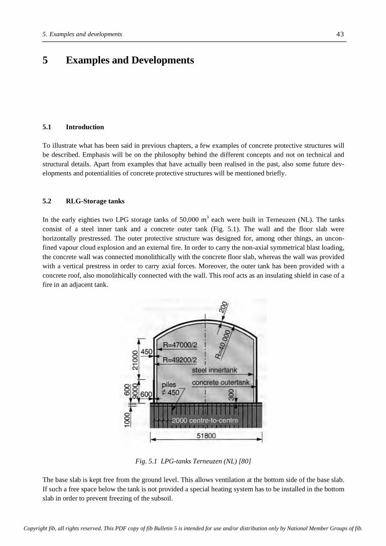
5. Examples and developments
43
5 Examples and Developments 5.1 Introduction To illustrate what has been said in previous chapters, a few examples of concrete protective structures will be described. Emphasis will be on the philosophy behind the different concepts and not on technical and structural details. Apart from examples that have actually been realised in the past, also some future dev-elopments and potentialities of concrete protective structures will be mentioned briefly. 5.2 RLG-Storage tanks In the early eighties two LPG storage tanks of 50,000 m3 each were built in Terneuzen (NL). The tanks consist of a steel inner tank and a concrete outer tank (Fig. 5.1). The wall and the floor slab were horizontally prestressed. The outer protective structure was designed for, among other things, an uncon-fined vapour cloud explosion and an external fire. In order to carry the non-axial symmetrical blast loading, the concrete wall was connected monolithically with the concrete floor slab, whereas the wall was provided with a vertical prestress in order to carry axial forces. Moreover, the outer tank has been provided with a concrete roof, also monolithically connected with the wall. This roof acts as an insulating shield in case of a fire in an adjacent tank.
Fig. 5.1 LPG-tanks Terneuzen (NL) [80] The base slab is kept free from the ground level. This allows ventilation at the bottom side of the base slab. If such a free space below the tank is not provided a special heating system has to be installed in the bottom slab in order to prevent freezing of the subsoil.
Copyright fib, all rights reserved. This PDF copy of fib Bulletin 5 is intended for use and/or distribution only by National Member Groups of fib.

fib Bulletin 5: Protective systems against hazards 44
Meanwhile such a prestressed concrete containment - bottom and roof monolithically connected to the wall forms the standard outer tanks for storage systems for refrigerated liquefied gases in many countries. 5.3 Inground and in-pit solutions With the aim to reduce the vulnerability of storage systems, tanks can be placed inground or in a pit. The inground tank technology has been developed primarily in Japan and is often used there. Inground tanks with a capacity of 140,000 m3 have been taken into service in 1989 [89]. Examples of in-pit solutions are the LNG-projects in Zeebrugge, Belgium, and the Revythousa, Greece. These projects comprise three 87,000 m3, built in the early eighties, and two 65,000 m3 LNG tanks which are still under construction. Apart from safety reasons also aesthetic reasons had played a role in the decision for the in-pit concept. By placing the tanks in a tank pit the "horizon pollution" could be reduced substantially.
Fig. 5.2 In-pit concept for LNG-storage tanks. Zeebrugge (B). 87,000 m3 tank 5.4 A-seismic design of tank systems With the aim to reduce the structural forces exerted by an earthquake, protective structures can be provided with seismic isolators. The purpose of these isolators is to assure that the sensitive and critical parts of a structural system remain outside the resonance range of the response spectrum of severe earthquakes. In Fig. 5.3a the principle of base isolation is exemplified by the LNG storage tanks built in Revythousa, Greece. The effect of seismic isolators on the structural response is shown schematically in Fig. 5.3b. A better and more reliable control of the structural forces allows reduction of the required resistance without a decrease of safety. Provisions will have to be provided, however, to allow larger deformations of the structure and at connections with piping, cables, etc.
+30.00m
+22.00m
+14.00m
+8.00m
-7.00m
1.0m
insulationLNG - 87000m
3
slurry wall concrete
2.2m3.2m
Bartoon clay
steelR=36m
i
R =42.00mu
-10.20m
R=90.7m
Copyright fib, all rights reserved. This PDF copy of fib Bulletin 5 is intended for use and/or distribution only by National Member Groups of fib.
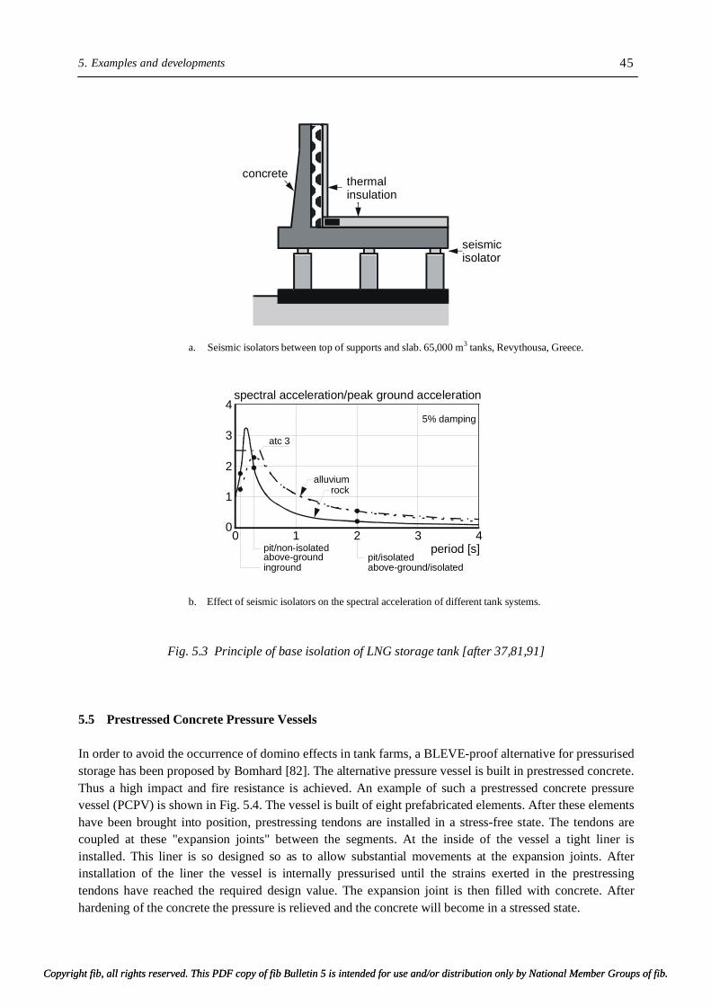
5. Examples and developments
45
a. Seismic isolators between top of supports and slab. 65,000 m3 tanks, Revythousa, Greece.
b. Effect of seismic isolators on the spectral acceleration of different tank systems.
Fig. 5.3 Principle of base isolation of LNG storage tank [after 37,81,91] 5.5 Prestressed Concrete Pressure Vessels In order to avoid the occurrence of domino effects in tank farms, a BLEVE-proof alternative for pressurised storage has been proposed by Bomhard [82]. The alternative pressure vessel is built in prestressed concrete. Thus a high impact and fire resistance is achieved. An example of such a prestressed concrete pressure vessel (PCPV) is shown in Fig. 5.4. The vessel is built of eight prefabricated elements. After these elements have been brought into position, prestressing tendons are installed in a stress-free state. The tendons are coupled at these "expansion joints" between the segments. At the inside of the vessel a tight liner is installed. This liner is so designed so as to allow substantial movements at the expansion joints. After installation of the liner the vessel is internally pressurised until the strains exerted in the prestressing tendons have reached the required design value. The expansion joint is then filled with concrete. After hardening of the concrete the pressure is relieved and the concrete will become in a stressed state.
4
3
2
1
00 1 3 4
spectral acceleration/peak ground acceleration
period [s]
5% damping
pit/non-isolatedpit/isolated
alluvium
atc 3
rock
above-ground/isolatedabove-groundinground
2
seismicisolator
thermalinsulation
concrete
Copyright fib, all rights reserved. This PDF copy of fib Bulletin 5 is intended for use and/or distribution only by National Member Groups of fib.Copyright fib, all rights reserved. This PDF copy of fib Bulletin 5 is intended for use and/or distribution only by National Member Groups of fib.

fib Bulletin 5: Protective systems against hazards 46
A PCPV built according to the procedure out-lined here meets the test requirement for steel pressure vessels imposed by the Dutch Boiler Inspectorate. In [78] it was shown that in an external fire a PCPV performs much better than conventionally designed pressure vessels.
a. PCPV - layout of prestressing cables b. PCPV: Cross section of the wall
Fig. 5.4 Prestressed concrete pressure vessel. Tendon lay-out and cross section of a wall [82] If PCPV's were used in tank parks the probability of domino effect would be negligible. Further more, as shown in Fig. 5.5, several studies have revealed that PCPV's can be built at a cost comparable to equivalent steel vessels. 5.6 Blast resistant control building A control building for a chemical plant in Fos sur Mer (Fr) had to be designed for a blast wave. Blast over-pressures had to be considered of 20, 70 and 100 kPa with positive phase durations of 100, 20 and 30 milliseconds, respectively. The velocity of the blast wave was determined as a function of the peak over pressure and ranged between 300 and 425 m/s. The external dimensions of the building were 5.8 x 33.0 x 38.0 m (height x width x length). The floor and the roof consist of a framework of horizontal beams (Fig. 5.6). Together with the concrete floor slab and roof slab these frames act as a horizontal diaphragm. These diaphragms are separated vertically by columns. These columns are supposed to act as "wheels", which allow the roof to move over a certain distance in horizontal direction when loaded by a blast loading. Schematically this "wheel concept" is shown in Fig. 5.7. The columns are clamped between the floor slab and the roof by vertical prestressing ca-bles. At the top and bottom part of the column these cables are unbonded over a certain distance. When the columns rotate, the prestressing cables are stretched. The possibility of the structure to move horizontally while stretching the strands gives the structure a favourable dynamic behaviour.
Copyright fib, all rights reserved. This PDF copy of fib Bulletin 5 is intended for use and/or distribution only by National Member Groups of fib.
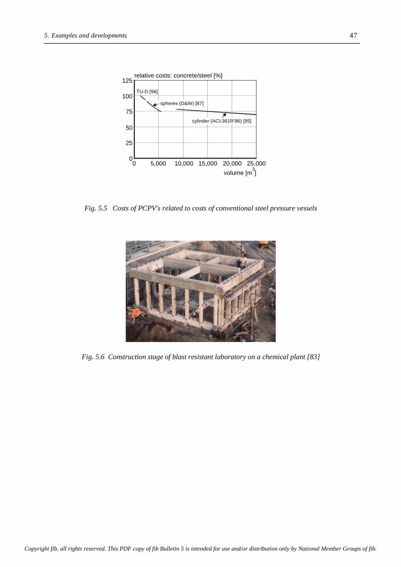
5. Examples and developments
47
Fig. 5.5 Costs of PCPV's related to costs of conventional steel pressure vessels
Fig. 5.6 Construction stage of blast resistant laboratory on a chemical plant [83]
125
100
75
50
25
0
relative costs: concrete/steel [%]
TU-D [96]
10,0005,000 15,000 20,000 25,000volume [m ]
30
spheres (D&W) [87]
cylinder (ACI-361R'86) [95]
Copyright fib, all rights reserved. This PDF copy of fib Bulletin 5 is intended for use and/or distribution only by National Member Groups of fib.

fib Bulletin 5: Protective systems against hazards 48
m = mass of the roof; F(t) = dynamic loading
S1, S2 = force in the column strands
Fig. 5.7 Concrete columns designed as "wheels", allowing horizontal displacement of the roof [83]
5.7 Multi-barrier waste storage system In Chapter 4 it was concluded, that for environmentally safe storage of hazardous waste a multi-barrier system would be a minimum requirement. That would enable control and, in some cases, also repair of the system in case of leakage. Examples of concepts, that meet the requirement of controllability and reparabi-lity, are given with the EPA-solution [67] and the waste dump Flotzgrün in Germany. Waste dump Flotzgrün (industrial waste) In 1986 a storage system for industrial waste was built on a small island in the river Rhine near Ludwigshaven (D). A cross section of the dump and a detail of the sealing system are shown in Fig. 5.8a,b. The sealing system consists of, among other things, two synthetic liners which are connected with each other in such a way that square pockets, 50 x 50 m, are formed. Between the liners a gravel layer is designed. This layer is monitored continuously. In case of leakage of the upper liner the gravel layer in the leaking pocket will be sealed by injection of a suitable (not specified) material. Although this system must be considered as another step in the evolution of dump design, there are still some questions. A major point of doubt concerns the reliability of effectiveness of the repair. Moreover, one should bear in mind that repair is possible only once. It can be doubted whether this is sufficient when the long-term performance has to be judged. It is particularly the time aspect, which renders this concept into, in essence, a false solution. All control devices under or in a waste body with a thickness of several meters are not accessible and, therefore, not easy to inspect. The period for which the (active) devices are designed is generally limited. Moreover, in practice it will not be easy to find people who will take the responsibility for proper function-ing in the far future. The main advantage of the presence of the control devices is that during the operation, i.e. filling, of the dump severe damages and mal-functioning of the system can be noticed and repair work can be carried out. Although this is not unimportant, it can not be judged as an environmentally entirely safe solution, but as a solution with a certain redundancy only.
mF(t)
b
h
s2 s1
? x
! !
½
Copyright fib, all rights reserved. This PDF copy of fib Bulletin 5 is intended for use and/or distribution only by National Member Groups of fib.

5. Examples and developments
49
a. Cross section of the dump in Flotzgrün b. Detail of bottom sealing
Fig. 5.8 Flotzgrün - Dump for industrial waste C2-Dump - Rotterdam In the Rotterdam area a storage structure for non-treatable industrial wastes, like metal sludge, leather tanning sludge and gas scrubber sludge has been built in late eighties. The storage capacity is 210,000 m3 and is scheduled to be filled completely after 10-15 years. The scheduled lifetime is 150 years. The structure has a rectangular box shape and is divided into two sections by a vertical concrete wall. The smaller section, about 15% of the total capacity, will be filled with waste containing more than 2% by weight of lead, chromium, copper and nickel. The system consists of an outer container of reinforced concrete, 320 x 50 x 12 m. The maximum permiss-ible crack width was 0.2 mm. The concrete floor was made without expansion joints and was, therefore, provided with a series of shrinkage strips. The walls were installed with expansion joints 40 m apart. Cracks that developed during the construction phase have been injected.
high water dam
filling material
tight barrier
anaerob degradablesubstance
protective barrier/inert material
surface sealing
leakage water shaft
tight barrier
tight barrier
separation liner
leakage drain
inspection pipeinjection pipe
foil
waste
gravel filter
gravel filter
fine sand
fine sandfilling
hard rock
Copyright fib, all rights reserved. This PDF copy of fib Bulletin 5 is intended for use and/or distribution only by National Member Groups of fib.

fib Bulletin 5: Protective systems against hazards 50
Fig. 5.9 C2-dump in Rotterdam [NL] for storage of hazardous non-tractable waste (after [84]) A cross section of the structure is shown in Fig. 5.9. The concrete walls are protected with a 2 mm thick HDPE-liner. The bottom liner must form a tight barrier between the waste and the environment for a specified drainage period of at least 30 years. The bottom liner consists of a crack-bridging rubber bitumen membrane and a 100 mm thick cast asphalt layer, which forms the sealing layer. On the asphalt layer a 0.75 m thick drainage layer is constructed of coarse sand, which contains a system of HDPE-pipes. A control and security system has been provided under the tank. Monitoring of leakage to the ground water is pos-sible by a drainage system. Six observation wells have been placed round the landfill. Leachate percolate and clean water are pumped to separate reservoirs. A movable roof, resting on the top of the walls, covers the waste. After filling the waste will be covered with two layers of HDPE-liners with a bentonite-clay layer in between. On top of this layer a sand layer will be placed to create an artificial dune. Although the C2-dump must be considered as one of the most advanced systems built so far, it is still a kind of temporary emergency solution. The question on the character of the waste and the interaction with its environment after the predicted lifetime has expired remains open. An open question also regards the life-time of the HDPE-sealing. Repair of the sealing during the lifetime of 150 year, and possibly thereafter, will be problematic and will require emptying of the structure. In other words, the functioning of the whole system strongly depends on materials technology, i.e. on the stability of the encapsulating material. System technology: Repairable containment systems In Fig. 5.10 an example is shown of a storage system with modular design for interim and long-term storage of untreated and untreatable waste, developed by the companies DYWIDAG and STEULER. The containment consists of prefabricated elements, supported by load-bearing frames of reinforced concrete. The elements are provided with a sealing material of 5-10 mm thick HDPE- of PFDE-plates. Above the sealing layer there is a filter layer, which serves to lead off possible leachate. The containment is inspectable and controllable from the outside all over. In case of leakage the sealing material, and if necessary also the pre-fabricated panels can be repaired or renewed. The repair process
HDPE liner
reinforced concrete pit 50.0 x 320.0m
gantry crane
back fill
sealing louvered slide
+16.0m
+5.00mdrainage and sealing210.000m
3
approach
movable roof
waste
Copyright fib, all rights reserved. This PDF copy of fib Bulletin 5 is intended for use and/or distribution only by National Member Groups of fib.

5. Examples and developments
51
Fig. 5.10 Storage of hazardous waste, designed according to system technology concept [86]
Fig. 5.11 Repair procedure for inner container [86] takes place in different steps as shown in Fig. 5.11. At first the waste is solidified and auxiliary columns are placed. The damaged part is removed and repaired or replaced by a new one. During the repair work the dump is still in operation. The repair or renewal operation can be performed without uncontrolled release of hazardous material to the environment. Thus full tightness of the systems is ensured for a long time. If in the final stage the roof of the container is still supported by columns special provisions may also be required to repair or replace damaged columns. In many cases, however, the columns only have a temporary function during the filling period of the container. In the final stage the waste is covered with, for example, a liner and a layer of soil.
load bearing frames Inner waste containmentwith sealing
Temporary roof
outer containment
waste
Local stabilization of the waste above elements to be replaced
Removal/replacement of damaged slab element
Copyright fib, all rights reserved. This PDF copy of fib Bulletin 5 is intended for use and/or distribution only by National Member Groups of fib.
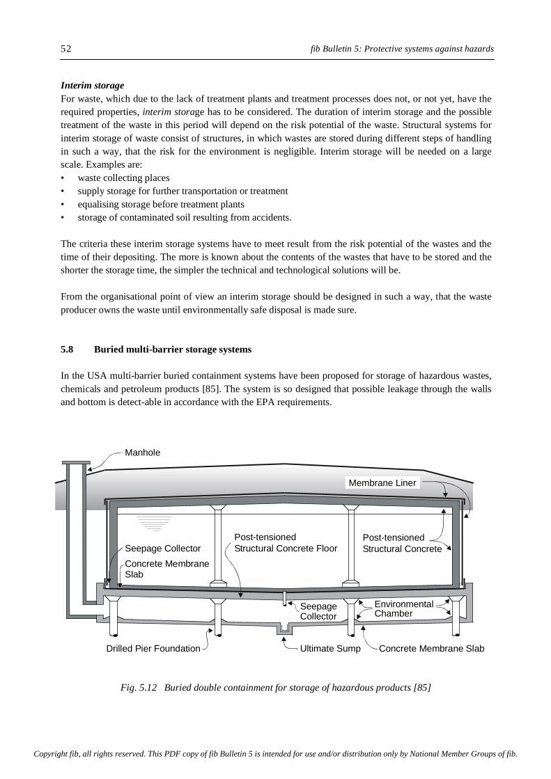
fib Bulletin 5: Protective systems against hazards 52
Interim storage For waste, which due to the lack of treatment plants and treatment processes does not, or not yet, have the required properties, interim storage has to be considered. The duration of interim storage and the possible treatment of the waste in this period will depend on the risk potential of the waste. Structural systems for interim storage of waste consist of structures, in which wastes are stored during different steps of handling in such a way, that the risk for the environment is negligible. Interim storage will be needed on a large scale. Examples are: • waste collecting places • supply storage for further transportation or treatment • equalising storage before treatment plants • storage of contaminated soil resulting from accidents. The criteria these interim storage systems have to meet result from the risk potential of the wastes and the time of their depositing. The more is known about the contents of the wastes that have to be stored and the shorter the storage time, the simpler the technical and technological solutions will be. From the organisational point of view an interim storage should be designed in such a way, that the waste producer owns the waste until environmentally safe disposal is made sure. 5.8 Buried multi-barrier storage systems In the USA multi-barrier buried containment systems have been proposed for storage of hazardous wastes, chemicals and petroleum products [85]. The system is so designed that possible leakage through the walls and bottom is detect-able in accordance with the EPA requirements.
Fig. 5.12 Buried double containment for storage of hazardous products [85]
Manhole
Drilled Pier Foundation Concrete Membrane SlabUltimate Sump
Structural Concrete FloorPost-tensioned
Seepage CollectorConcrete MembraneSlab
EnvironmentalChamber
SeepageCollector
Post-tensionedStructural Concrete
Membrane Liner
Copyright fib, all rights reserved. This PDF copy of fib Bulletin 5 is intended for use and/or distribution only by National Member Groups of fib.

5. Examples and developments
53
The prestressed concrete tank can supply the structural strength and the primary level of tightness. Non-structural liners or external membranes can be used to provide the secondary level of tightness. Between the primary and secondary barrier a leak detection system and a seepage collector are installed. Fig. 5.12 shows a circular prestressed concrete structure, provided with an external membrane (alternative-ly, an interior liner can be used) and an "environmental chamber" [85]. This chamber below the tank floor solves the problem of not being able to observe leakage through the tank floor. Repair works and/or renew-al of the system in case unpredicted chemical or biological actions may occur, however, might be hard to conduct. Obvious advantages of buried systems are the enhanced protection against sabotage, reduced environmental impact (no "horizon pollution") and substantial reduction of climate induced thermal loads. The double containment system with its reliable discharging system of leachate gives these systems a high degree of environmental safety. 5.9 Final comments Management of hazardous waste is a continuously developing business yet. With elapse of time people learn from experience and this experience may change, or at least modify, earlier adopted policies. In Germany thermal treatment of waste and a high degree of recycling as required by the "recycling-economy law", has reduced the amount of waste drastically in the past few years. Instead of the expected shortage of storage capacity there is now a situation of excessive free dumping capacity. These dumping sites, how-ever, have not been designed for storage of the type of waste that is left after thermal treatment. Situations like this clearly show how the waste business passes through a process of evolution. When discussing the different solutions for handling different types of waste, emphasis has been on the technical performance of the storage systems. Economics were not dealt with at all. It goes without saying that more advanced storage systems are generally more expensive, at least if only the initial investments and short-term costs are considered. A comparison of costs between different systems is only possible if systems are compared which meet the same set of criteria. Comparison of the costs of repairable and renewable systems with those of a system that can not easily be repaired and renewed would be unfair. That is to say, that a decision in favour of a certain system should not be made only on the basis of the (short term) costs, but on a comprehensive and consistent evaluation of the total cost for handling of the waste (pre-treatment, storage, monitoring, etc.). In case of leakage additional money has to be spent on decontamination. For some indicative figures about relative costs of different storage systems reference is made to Bomhard [90]. The cost aspect will be considered briefly in part III of this series.
Copyright fib, all rights reserved. This PDF copy of fib Bulletin 5 is intended for use and/or distribution only by National Member Groups of fib.
References
55
References 1 Häfele, W., 1990. "Energiesysteme im Uebergang". Poller AG & Co. Buchverlag, Landsberg/Lech, p.
691. 2 World Watch Institute, 1991. "Caring for the Earth". 3 Chacraborty, S., 1991. "Ethical and Social Aspects in Comprehensive Risk Assessment". Structural
Engineering International, Vol. 1, pp. 38-41. 4 Bomhard, H., 1992. "Concrete and Environment - An Introduction". Proc. Int. Symp. of the FIP,
Budapest, pp. 51-69. 5 Breugel, K. van, 1993. "Acceptance criteria for high consequence risks - A critical appraisal". ICOS-
SAR'93, Insbruck 6 Reid, S.G., 1989. "Risk acceptance criteria for performance-oriented design codes". ICOSSAR'89,
San Francisco, Vol. III, pp. 1911-1918. 7 Eibl, J., Cüppers, H.-H., 1992. "Core-melt proof nuclear reactor containments - A new generation",
Proc. Int. Symp. of the FIP, Budapest, pp. 129-147. 8 Breugel, K. van, 1991. "Concrete structures for consequence control in industrial accidents". Proc.
seminar Structural Design for Hazardous Loads, Brighton, E&FN Spon, pp. 357-366 9 Breugel, K. van, 1987. "Concrete and the economy of hazard protection". Int. Conf. on Concrete for
Hazard Protection, Edinburgh, pp. 3-14. 10 Breugel, K. van, 1992. "Structures and protective systems for prevention and containment of indu-
strial catastrophes: Design principles and examples" FIP-notes no. 3, pp. 10-15, no. 4, pp. 2-5. 11 Bomhard, H., 1991. "Prevention and containment of large scale technology-related accidents - Shell
and spatial structures as protective and safety measures". Bull. IASS, Vol. 32, no. 3. pp. 138-148. 12 Deutscher Ausschuß für Stahlbeton: "Richtlinie für Betonbau beim Umgang mit wassergefährdenden
Stoffen", September 1992, Teil 1: Entwurf und Bemessung unbeschichteter Betonbauteile. Teil 2: Überwachung unbeschichteter Betonbauteile und Konzept für den Schadensfall. 13 Breugel, K. van, 1986. "Potentialities of concrete in storage systems for liquefied gases and hazardous
products". Proc. 10th. Int. Congress of the FIP, New Delhi, Vol. IV, pp. 80-98. 14 Melchers, R.E., 1987. "Structural Reliability - Analysis and Prediction". John Wiley & Sons, New
York, 400 p. 15 IAE Wenen, 1987. "The accident at the Chernobyl' nuclear power plant and its consequences". Info.
bull,. Part 1. 56 p. 16 Schuhmacher, P., 1991. "Concrete and Environment - Concrete and Ecology" Beton- und Fertigteil-
technik, Vol. 8, pp. 27-29. 17 Breugel, K. van, 1987. "Domino effects in large-scale storage facilities". IFHP-IULA symposium
Prevention and Containment of Large-Scale Industrial Accidents. Rotterdam, pp. 135-139. 18 Geiger, W., 1977. "Conditions of external loading of nuclear power plant structures by vapour cloud
explosions and design requirements". 4th SMIRT, Vol. J10/9, San Francisco. 19 Breugel, K. van, 1994. "New strategies for environmental protection - The role of concrete
structures". Proc. FIP-XIIth Int. Congress, pp. K12-K17. 20 Manuele, F.A., 1984. "One hundred largest losses - A thirty year review of property damage losses in
the hydrocarbon-chemical industry". Loss Prevention Bulletin 038. pp. 1-11. 21 Blockley, D., 1993. "Structural failure and hazard engineering". Structural Engineering International,
Vol. 3, Number 4, pp. 253-257. 22 Reid, S.G., 1992. "Acceptable Risk". In Engineering Safety. McGraw-Hill, Ed. Blockley, pp. 138-
164. 23 Pidgeon. N.F., 1992. "The Psychology of Risk". In Engineering Safety. McGraw-Hill, Ed. Blockley,
pp. 167-184. 24 Proc. Int. Symp.: "The Chemical Industry after Bophal, IBC Technical Service Publication, 1985. 25 Pietersen, C.M., 1985. "Analysis of the LPG disaster in Mexico City, 1984". Gastech. 26 "Examples of structural systems for environmental protection". FIP-Report on Protective Systems -
Part II. In progress.
Copyright fib, all rights reserved. This PDF copy of fib Bulletin 5 is intended for use and/or distribution only by National Member Groups of fib.

fib Bulletin 5: Protective systems against hazards 56
27 "Engineering models for design of structural systems for environmental protection". FIP-Report on
Protective Systems - Part III. In progress. 28 Blockley, D.I., 1993. "Structural failure and hazard engineering". Structural Engineering
International, Vol. 3, No. 4, pp. 253-257. 29 Huppmann, H., 1994. "How safe is safe enough". Proc. 6th ICOSSAR Congress, Innsbruck, Vol. 1,
pp. 57-59. 30 Paloheimo, E., 1996. "The second industrial revolution". 15th. Int. IABSE Congress, Copenhagen, pp.
353-362. 31 Pugsley, A.G., 1951. "Concepts of Safety in Structural Engineering". J. Inst. Civ. Eng., Vol 36, No. 5.
pp. 5-51. 32 Ale, B.J.M., 1993. "Risks and risk perception (in Dutch). Proc. Symposium on applied risk analysis.
Delft, pp. 69-80. 33 British Advisory Committee on Major Hazards, 1984. "The control of major hazards", Third Report,
Health and Safety Executive, London. 34 Reid, S.G., 1992. "Acceptable Risk". in: Engineering Safety, Ed. Blockley, D.I., McGraw-Hill, pp,
138-166. 35 Zawlocki, Karen, R., 1986. "A study of hazardous waste management priorities for categories of
waste in Washington State". Dept. of Ecology, State of Washington. 36 Plichon, C., Jolivet, F., 1978. "Aseismic foundation systems for nuclear power stations". Proc. Eng.
design for earthquake environments. Int. of Mech. Eng., London, pp. 193-206. 37 Bomhard, H., 1992. "Revythousa island LNG facility - LNG storage tanks for seismically highly
affected sites". 10 Int. Conf. on LNG, Kuala Lumpur, 8 p. 38 Maki, E., 1996. "Environment-friendly and energy-conscious building design". 15th. Int. IABSE
Congress, Copenhagen, pp. 377-388. 39 Eibl, J., 1990. "Recommendations for concrete silo design". FIP-Working Group "Silo Design". 29 p. 40 Wingerden, C.J.M. van, Berg, A.C. van den, Opschoor, G., 1989. "Vapour cloud explosion blast
prediction". Plant/ Operations Progress, Vol. 8, No. 4, pp. 234-238. 41 Berg, A.C. van der, Wingerden, C.J.M. van, The, H.G. 1991. "Vapour cloud explosions:
Experimental investigation of key parameters and blast modelling". Trans. IChemE., Vol. 69, Part B. pp. 139-148.
42 Taffijn, E., 1988. "Loads and structural response caused by gas clouds explosions (in Dutch)". TU-Delft.
43 Turner, F.H., 1979. "Concrete and Cryogenics". Viewpoint Publication, C&C-Association, 100 p. 44 "Examples of structural systems for environmental protection". FIP-Report on Protective Systems -
Part II. In progress. 45 "Engineering models for design of structural systems for environmental protection". FIP-Report on
Protective Systems - Part III. In progress. 46 "Missiles generated by natural phenomena". 1981. SRD 3.5.1.4 US Nuclear Regulatory Commission. 47 FIP-Report 3/6, 1982. "Preliminary recommendations for the design of prestressed concrete
containment structures for the storage of refrigerated liquefied gases". 55p. 48 Bureau Veritas, 1984. "Liquefied gas storage installations under atmospheric pressure". Guidance
Note NI 002 CMI OCT. 84. 56 p. 49 EEMUA, 1986. "Recommendations for the design and construction of refrigerated liquefied gas
storage tanks". Publ. No. 147. ISBN 0-85931-113-9, London, 95 p. 50 DCMR, 1985. "Storage tanks for refrigerated liquefied gases with an outer concrete container".
Guidelines compiled by the Committee for cryogenic storage in concrete tanks. Rotterdam, 42 p. 51 Sullivan, P.J.E., 1992. "Methods of assessment of "near miss" and impact of missiles on reinforced
concrete structures". Int. Symp. FIP, Budapest, Vol. I, pp. 171-180. 52 Owen, J.I.H., 1978. "Infantry weapons of the NATO armies". ISBN 0-904609-34-0, Brassey's,
London. 53 Breugel, K. van, 1998. “How to deal with and judge the numerical results of risk analysis”.
Computers and Structures, 67, pp. 157-164. 54 Ramler, J.P.G., Breugel, K. van, 1989. "Impact: loads and response". TU-Delft, Res. Report, 25.5-89-
06/A1, 219 p.
Copyright fib, all rights reserved. This PDF copy of fib Bulletin 5 is intended for use and/or distribution only by National Member Groups of fib.

References
57
55 Bomhard, H., Kraemer, U., 1983. Liquefied gas tankage and earthquakes - A comparison of various
tank systems" Sec. Int. Conf. on Cryogenic Concrete. Amsterdam 56 Gesetz zur Ordnung des Wasserhaushalts (Wasserhaushaltsgesetz - WHG), Fassung vom 23.09.1986 57 Hahn, J., 1988. "Anforderungen an Abfallbehandlung und an Ablagerung unter Berücksichtigung der
Vielstoffproblematik" aus der Anhörung des niedersächsischen Umweltministeriums, Hannover 58 Grube, Spanke: "Dichtigkeit von Beton gegenüber organischen Flüssigkeiten" aus Beton 5/90 59 Neck, Spanke: "Dichtigkeit von Rohrbeton gegenüber CKW-Durchtritt" aus Beton 10/92 60 Zimbelmann, Burgbacher: "Über den Widerstand von Normebeton gegen Chlorkohlenwasserstoffe
(CKW)", Beton- und Stahlbetonbau 1/90 61 Allgemeine Verwaltungsvorschrift über die nähere Bestimmung wassergefährdender Stoffe und ihre
Einstufung entsprechend ihrer Gefährlichkeit (VwVwS), 09.03.1990 62 Hahn, J., 1990. "Konzept einer umweltfreundlichen Entsorgung" in: "Das bessere Müllkonzept -
Chaos nach dem Volksentscheid?", Kongre�begleitheft, Fürth 28./29.11.1990 63 Hahn, J., 1990. "Inertisierung vor der Ablagerung - Pro und contra (Rest-) Müllverbrennung" in:
Wiemer, K., Abfallwirtschaft und Deponietechnik '90, in: Abfallwirtschaft Bd. 5, Witzenhausen 64 Gesetz über die Vermeidung und Entsorgung von Abfällen, Abfallwirtschaftsgesetz - AbfG, Fassung
August 1986 65 TA-Abfall, Gesamtfassung der Zweiten allgemeinen Verwaltungsvorschrift zum Abfallgesetz,
Fassung vom 01.04.1991. 66 TA-Siedlungsabfall, Dritte Allgemeine Verwaltungsvorschrift zum Abfallgesetz, Technische Anle-
itung zur Verwertung, Behandlung und sonstigen Entsorgung von Siedlungsabfällen sowie ergänzende Empfehlungen zur TA Siedlungsabfall des Bundesministeriums für Umwelt, Naturschutz und Reaktorsicherheit, 1. Auflage, Stand Juni 1993.
67 US-EPA, 1989: "Requirements for Hazardous Waste Landfill - Design, Construction and Closure", Seminar Publication, EPA/625/4-89/1022, August 1989.
68 "Large storage area fire". Loss Prevention Bulletin 094, pp. 26-29. 69 Andersson, B.O., 1991. "March 20, 1989 Accident in Lithuanian Fertilizer Plant". American Inst. of
Chem. Eng., Technical Manual, Vol. 31, pp. 5-7 70 "Structural analysis and design of nuclear plant facilities". 1980. ASCE-Manuals and reports on
engineering practice - no. 58, ISBN 0-87262-238-X, New York. 71 Stief, K., 1986. Das Multibarrierekonzept als Grundlage von Planung, Bau, Betrieb und Nachsorge
von Deponien. In: Müll und Abfall, Heft 1. S. 15 - 20 72 Eidgenössisches Department des Innern, Technische Verordnung über Abfälle (TVA), Dezember
1988 73 Bundesministerium für Land- und Forstwirtschaft und für Umwelt, Jugend und Familie (Hrsg.):
Richtlinien für die Ablagerung von Abfällen, Wien, September 1990. 74 Köppke, Freundling, v. Hagel, 1991. "Stauwasserbehandlung auf der Altdeponie Georgswerder",
Entsorgungspraxis 5/91, S. 252 75 Wolf, Zarth, 1989. "Die Deponie Hamburg-Georgswerder: Entstehung, Umweltfragen, Sanierung",
Wasser + Boden, Heft 9, Verlag Paul Parey. 76 Dr. Piels, Dr. Gronemeier, 1989. Consulting GmbH, "Gutachten zur Sicherung der Sonderabfallde-
ponie Münchehagen", Kiel. 77 Montague, P., 1984. "The limitations of Land-filling". in Beyond dumping, London, pp. 3-18. 78 Breugel, K. van, Asin, M., 1992. "Concrete structures for risk reduction on industrial plants". Proc.
14th. IABSE congress, New Delhi, pp. 95-100. 79 Breugel, K. van, et.al., 1983. "Concrete structures for storage of refrigerated liquefied gases" (in
Dutch), STUVO-report No. 70, 's Hertogenbosch, 251 p. 80 Bilderbeek, W., 1983. "Construction of LPG storage tanks in prestressed concrete - DOW-chemical,
Terneuzen". 2nd Int. Conf. on Cryogenic Concrete, Amsterdam, 8 p. 81 Baumann, T., Aigner, F., 1992. "Design of the prestressed outer concrete containment of LNG-
storage tanks". DYWIDAG-publication, 13 p. 82 Bomhard, H., 1987. "Concrete structures as a preventive answer to environmental catastrophs".
IABSE-Symposium Concrete Structures for the Future", Versailles. 8 p.
Copyright fib, all rights reserved. This PDF copy of fib Bulletin 5 is intended for use and/or distribution only by National Member Groups of fib.
fib Bulletin 5: Protective systems against hazards 58
83 Ronde, M., 1992. "Blast resistant control buildings". Proc. FIP-symposium, Budapest, Vol. I, pp, 181-
186. 84 Sijberden, H.L.: "Design and Construction of the C2-Landfill Maasvlakte Rotterdam" 85 Close, S.R., Jorgensen, I.F., "Use of circular prestressed concrete tanks for containment of hazardous
materials". SP, 19 p. 86 Rudat, D., 1992. "Design principles and examples of structures for treatment and containment of
hazardous waste". FIP-symposium, Budapest, Vol. 1, pp. 91-128. 87 Bomhard, H., 1986. "Concrete Pressure Vessels - The preventive answer to the Mexico City LPG
disaster", GASTECH '86, Hamburg, pp. 415-421. 88 Derham, C.J., Thomas, A.G., Kelly, J.M., 1987. "A rubber bearing system for seismic protection of
structures". Proc. Engineering design for earthquake environments. Inst. of Mech. Eng., London, pp. 53-58.
89 Goto, S., Sabo, Y., Kamiya, A., Shibuya, M., 1989. Present status of LNG inground tank technology in Japan. Proc. LNG/Nissan, 23 p.
90 Bomhard, H., 1986. "Deponiesysteme für vorbehandelte und nicht vorbehandelte Abfälle (Storage systems for pre-treated and untreated wastes)". Proc. Symp. "Die Deponie - ein Bauwerk?", TU-Aa-chen, 24 p.
91 Bomhard, H., Stempniewski, L., 1993. "LNG Storage Tanks for seismically highly affected sites". Int. Post-SMIRT Conference Seminars, Italy, 12 p.
92 Bomhard, H., 1992. "Die sichere Umschließung gefährlicher Stoffe bei Unfällen - Konzept eines Schutztechnik". Beton- und Stahlbetonbouw, Heft 4, 8 p.
93 Eibl, J., 1994. "Zur bautechnischen Machbarkeit eines alternatieven Containment für Drukwasserreaktoren - Stufe 3”. Kernforschungszentrum, Karlsruhe.
94 Breugel, K. van, 1997. "Beyond the Risk Concept". Proc. 7th Int. Conference on Structural Safety and Reliability, Kyoto, Vol. I, pp. 255-262.
95 Chow, P.Y, et al., 1986. "Composite Concrete and Steel High-Pressure Vessels for General Industrial Use". ACI-Committee 361, Report ACI 361R-86, 91 p.
96 Mans, A., Anneeze, M., 1989. “Pressurized storage for industrial use (in Dutch)”. Master thesis TU-Delft, 122 p.
97 Ministry of Social Affairs (NL) “Report on blast at DSM at Beek (NL), 7 November 1975”. Part I, 145 p., Part II, 76 p.
Copyright fib, all rights reserved. This PDF copy of fib Bulletin 5 is intended for use and/or distribution only by National Member Groups of fib.