project - Copy
27
MULTIMETER DESIGN USING VHDL Presented by: o Mohit Mukul 1104030 o Harsh Prakash Singh 1104062 o Rahul Kumar 1104063 Under the supervision of : Dr. Bijay Kumar Sharma DEPARTMENT OF ELECTRONICS & COMMUNICATION ENGINEERING, NIT PATNA
-
Upload
piedaholic -
Category
Documents
-
view
18 -
download
1
Transcript of project - Copy

MULTIMETER DESIGN USING VHDL
Presented by:o Mohit Mukul 1104030o Harsh Prakash Singh 1104062o Rahul Kumar 1104063
Under the supervision of : Dr. Bijay Kumar Sharma
DEPARTMENT OF ELECTRONICS & COMMUNICATION ENGINEERING, NIT
PATNA

Introduction Mechanism description Work done till now Conclusions derived from the former Work to be done in the upcoming future References
Phases of the project

The objective of our project is to design, build and test a multimeter comparable in performance to the multimeters available at the ECE laboratories. The Altera DE2 board is an integral part of the project as it is used to implement the logic component of our circuit (programmed via VHDL) and is also utilized for its LED and LCD displays to showcase the functionalities of our multimeter. The basic design of the VHDL code is a system to o Control the flows of the following states- Reset/Display,
Count-Up, Set-Sign, Countdown and Binary-BCD Decoding o Manipulate the four registers to fluctuate between the
ohmmeter, voltmeter, ammeter and the Beta calculations. o Use the LCD drivers to signal the current state
Introduction

• The DE2 board is synchronized with a simple voltmeter circuit, which would consist of an integrating operational amplifier, comparator, multiplexer and relay switches to perform the tasks written in the VHDL code.
• The voltmeter would be the platform on which the other components would rely.
• The ohmmeter requires the voltmeter and is built by providing a constant current of 0.01 mA through the unknown resistor. By measuring the voltage across the resistor, the value is calculated using the formula R=V/0.01mA.

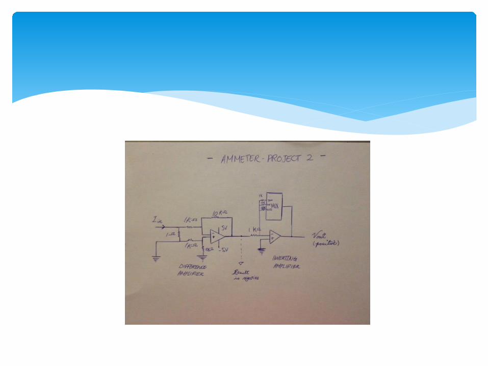
• The ammeter also relies on the voltmeter and is built using a difference and inverting amplifier.
• A power source is required that could provide our circuit with positive and negative voltages. The basic building block for the power source is a transformer to step down the AC voltage. Various other components would be then used to convert the AC voltage to DC voltage. The negative 5 voltages are then achieved by using different sides of the diode bridge.
• Armed with knowledge of circuit theory, our group would be successfully able to construct a complicated yet efficient circuit.
The multimeter using VHDL is an electrical apparatus most commonly used in electrical engineering. Multimeter can change to different modes, which are voltmeter, ammeter, ohmmeter, and beta β calculator. It is built by chips soldering on silicon electric circuit boards, and run by Altera DE2 board. We use VHDL to control the function of the DE2 board. Then the DE2 board will send signals to the electric circuit board. A black rectangular box encloses all electric circuit boards. The DE2 board is put on top of the box. The major parts of AMR are: VHDL code Power Supply Voltmeter Ammeter Ohmmeter Beta β Calculator Metal Enclosure
Mechanism Description
2.0 Part-by-part Description The following is a description of main parts of the advanced multimeter.
2.1 VHDL code The De2 board and VHDL has served as a brain of our multimeter. It works as counters, registers, many types of decoders, multiplexers, drivers, range checking module, and most importantly, state machine.


The state machine has five states: Reset/Display Count-Up Set-Sign Count-Down Binary-BCD Decoding

When it is in Resetting state, it will reset the integrator by shortening capacitor, reset all registers (with exception to Down Counter, which is reset in Count-Up) and store the new 5 digit BCD value to register for display. This display stores this value until the end of next cycle, when it receives a new value.
In Count-Up stage, up-counter is enabled to measure 500ms, while DE2 board outputs signal to enable Vin to be passed to integrator. After 500ms has passed, the counter will signal the state machine to proceed to next state.

In the state Set-Sign, the output of comparator from voltmeter circuit is inverted 8 and stored in a latch. This value will be used as sign. If the output of integrator at this point is higher than ground, it means the Vin was negative, and vice versa. The output of this latch is also passed to the multiplexer on circuit to decide which reference voltage to use (+ or - 5v).

The state machine will stay in the next stage, Count-Down, until the comparator output from circuit is changed, either from high to low(negative sign), or low to high(positive sign). The Down-Counter will be enabled at this stage to measure the time in binary. In the final stage. This binary value is decoded into BCD. The reason we do not count down in BCD to start with is for easier computation of the value.

4 bit register is used to hold current mode(voltmeter, ammeter, ohmmeter, beta). 4 push buttons on DE2 board are used to switch between each mode, and this register holds the value after the buttons have been released.
The Range Check is also embedded in the VHDL. However it does not take a part of state machine; it runs simultaneously. The Range Checker receives input from Down-counter. It compares the value to different ranges according to different modes. For example, in voltmeter, it compares the value to 1V and 10V, and assign one of three ranges. depending on this range, the location of decimal point and which 5 digits out of originally received 7 digits to display.

The last module in VHDL is LCD Driver. It acts as a driver to write one of five messages on LCD display. Four messages indicate the mode and units, and one as a welcome screen. The ASCII codes are pre-coded into VHDL, and message is determined by current mode
2.2 Power Supply In order to power up all the chips in our
circuit, we need to create a power supply. We use a diode bridge circuit to step down and rectify the AC voltage from the transformer to get a full wave rectified voltage. Then we add a decoupling capacitor to the circuit to reduce the ripple voltage.

2.3 Voltmeter The voltmeter circuit is relatively simple and includes only few chips: integrating op amp comparator a multiplexer few switchesThe multiplexer is used to provide reference voltage according to the sign of Vin, the 2 switches are used as a multiplexer to choose between Vin and reference voltage (since the multiplexer chip is unable to handle more than 11 volts). The integrating op amp and and comparator as the main part of ADC. Also, a switch is used to reset the integrator. The circuit communicates with the DE2 board to work as a full voltmeter.


2.4 Ammeter The components of an ammeter are as follows: A differential amplifier An inverting amplifier A multiplexer chip which switches between
three different channels, selecting three different resistance values made available for the necessary multiplexer conversion

2.5 Ohmmeter The ohmmeter consists of four different constant current sources for each one of the ranges.
fig. A current source

2.6 Beta β Calculator There are two kinds of transistors we need to measure, NPN &
PNP transistor. For both transistors, we set the base current (Ib) to 0.1 mA by using a constant current source circuit. A variable resistor is used to make an accurate value for the resistor to make 0.1mA. As a transistor can act as a current amplifier, Ic is amplified by β times Ib, i.e. Ic = β x Ib.
Then we measure the voltage across the 100 ohm resistor(Vc1,Vc2) in the collector, and we will know the current Ic because the voltage display divided by 100 will be the current value, from the equation V=I x R. As Ib is set to 0.1mA, so the voltage display is actually showing the beta value divided by 100.


Work done till now

Work to be done in future

[1]"Slope (integrating) ADC." : DIGITAL-ANALOG CONVERSION. N.p., n.d. Fri. 20 Oct. 2012. <http://www.allaboutcircuits.com/vol_4/chpt_13/8.html>.
[2] "Www.datasheetcatalog.com." Www.datasheetcatalog.com. 21 Oct. 2012 < http://www.datasheetcatalog.org/datasheet/stmicroelectronics/1981.pdf >.
[3]"How Analog-to-Digital Converter (ADC) Works | Hardware Secrets." How Analog-to-Digital Converter (ADC) Works | Hardware Secrets. N.p., n.d. Sat. 21 Oct. 2012. <http://www.hardwaresecrets.com/article/How-Analog-to-Digital-Converter-ADC-Works/317/8>.
[4]”Current Source”. Current source From Wikipedia, the free encyclopedia N.p. 14 Nov 2012. Retrieved 20 Nov.2012< http://en.wikipedia.org/wiki/Current_source>
[5]”DE2 Development and Education Board User Manual.” Altera DE@ Board ALTERA. 16 Nov. 2012 < ftp://ftp.altera.com/up/pub/Webdocs/DE2_UserManual.pdf>
[6]”VHDL”. ALTERA VHDL. N.p., 2012, 10 Nov. 2012. <http://www.altera.com/support/examples/vhdl/vhdl.html>
References

Thank you
Please give us a feedback