Programming Manual for “-B” Instruments · 2019-03-05 · Programming Manual for “-B”...
60
Programming Manual for “-B” Instruments Firmware Revision 5.07 and later The latest version of this manual is also available at http://www.avtechpulse.com/manuals/programming/programming.pdf AVTECH ELECTROSYSTEMS LTD. NANOSECOND WAVEFORM ELECTRONICS SINCE 1975 [email protected] http://www.avtechpulse.com/ Tel: 888-670-8729 (USA & Canada) or +1-613-686-6675 (Intl) Fax: 800-561-1970 (USA & Canada) or +1-613-686-6679 (Intl) BOX 5120, LCD MERIVALE OTTAWA, CANADA K2C3H5
Transcript of Programming Manual for “-B” Instruments · 2019-03-05 · Programming Manual for “-B”...

Programming Manualfor “-B” Instruments
Firmware Revision 5.07 and later
The latest version of this manual is also available athttp://www.avtechpulse.com/manuals/programming/programming.pdf
A V T E C H E L E C T R O S Y S T E M S L T D .N A N O S E C O N D W A V E F O R M E L E C T R O N I C S
S I N C E 1 9 7 5
[email protected]://www.avtechpulse.com/
Tel: 888-670-8729 (USA & Canada) or +1-613-686-6675 (Intl)Fax: 800-561-1970 (USA & Canada) or +1-613-686-6679 (Intl)
BOX 5120, LCD MERIVALEOTTAWA, CANADA K2C3H5

ii

iii
WARRANTY
Avtech Electrosystems Ltd. warrants products of its manufacture to be freefrom defects in material and workmanship under conditions of normal use. If,within one year after delivery to the original owner, and after prepaid return bythe original owner, this Avtech product is found to be defective, Avtech shall atits option repair or replace said defective item. This warranty does not apply tounits which have been dissembled, modified or subjected to conditionsexceeding the applicable specifications or ratings. This warranty is the extent ofthe obligation assumed by Avtech with respect to this product and no otherwarranty or guarantee is either expressed or implied.
TECHNICAL SUPPORT
Phone: 888-670-8729 (USA & Canada) or +1-613-686-6675 (International)Fax: 800-561-1970 (USA & Canada) or +1-613-686-6679 (International)
E-mail: [email protected] Wide Web: http://www.avtechpulse.com

iv
v
TABLE OF CONTENTS
1.Controlling Your Instrument.......................................................................................................................11.1.Introduction......................................................................................................................................... 1
1.1.1.Mixing Control Modes..................................................................................................................11.2.Local Control...................................................................................................................................... 2
1.2.1.Introduction.................................................................................................................................. 21.2.2.The Keypad and Other Controls..................................................................................................21.2.3.Menu Layout................................................................................................................................ 21.2.4.Trigger Menu................................................................................................................................ 41.2.5.Shape Menu................................................................................................................................. 41.2.6.Delay Menu.................................................................................................................................. 41.2.7.Pulse Width Menu........................................................................................................................51.2.8.Rise Time (TR) Menu................................................................................................................... 51.2.9.Amplitude Menu........................................................................................................................... 51.2.10.Offset Menu............................................................................................................................... 51.2.11.N Menu (Burst Count)................................................................................................................61.2.12.Burst Menu................................................................................................................................. 61.2.13.Monitor Menu............................................................................................................................. 61.2.14.ZOUT Menu............................................................................................................................... 61.2.15.Load Menu................................................................................................................................. 61.2.16.Output Menu.............................................................................................................................. 61.2.17.Invert Menu................................................................................................................................ 61.2.18.Active Menu............................................................................................................................... 71.2.19.Logic Level Menu.......................................................................................................................71.2.20.Gate Menu................................................................................................................................. 71.2.21.Control Menu............................................................................................................................. 71.2.22.Memory Menu............................................................................................................................ 71.2.23.Setup Menu................................................................................................................................ 8
1.3.Introduction to the RS-232 Serial Bus.................................................................................................91.3.1.Introduction.................................................................................................................................. 91.3.2.RS-232 Communications Settings...............................................................................................91.3.3.Cable Connections..................................................................................................................... 101.3.4.Computer Requirements............................................................................................................101.3.5.Step-By-Step Example For First-Time Use................................................................................10
1.4.Introduction to the GPIB IEEE-488.2 Bus.........................................................................................121.4.1.Introduction................................................................................................................................ 121.4.2.Controller and Cabling Requirements........................................................................................121.4.3.Step-By-Step Example For First-Time Use................................................................................121.4.4.IEEE 488.1 Interface Functions..................................................................................................131.4.5.End-of-String (EOS) Issues........................................................................................................141.4.6.Other GPIB Notes...................................................................................................................... 141.4.7.Debugging GPIB Problems........................................................................................................141.4.8.GPIB Troubleshooting Checklist................................................................................................15
1.5.Introduction to the Ethernet Port.......................................................................................................161.5.1.Introduction to the -VXI Option...................................................................................................161.5.2.IP Address Configuration...........................................................................................................171.5.3.Security...................................................................................................................................... 181.5.4.Web Console............................................................................................................................. 181.5.5.Troubleshooting......................................................................................................................... 18
2.Programming Commands....................................................................................................................... 192.1.Command Format............................................................................................................................. 19
2.1.1.Numeric Values.......................................................................................................................... 192.1.2.Units........................................................................................................................................... 192.1.3.Query Commands...................................................................................................................... 212.1.4.Minimum and Maximum Values.................................................................................................212.1.5.Multi-channel Instruments..........................................................................................................212.1.6.Compound Messages................................................................................................................212.1.7.Maximum Command Lengths....................................................................................................222.1.8.Command Execution Order and Coupled Commands...............................................................22

vi
2.1.9.Execution Speed........................................................................................................................ 222.2.The CALIBRATION Command Hierarchy.........................................................................................23
2.2.1.Tree Structure:........................................................................................................................... 232.2.2.CALibration:[ALL]....................................................................................................................... 232.2.3.CALibration:FREQuency............................................................................................................23
2.3.The DIAGNOSTIC Command Hierarchy..........................................................................................242.3.1.Tree Structure:........................................................................................................................... 242.3.2.DIAGnostic:AMPLitude:CALibration...........................................................................................242.3.3.DIAGnostic:MONitor:CALibration...............................................................................................242.3.4.DIAGnostic:MONitor:STEP........................................................................................................252.3.5.DIAGnostic:OFFSet:CALibration................................................................................................25
2.4.The MEASURE Command Hierarchy...............................................................................................262.4.1.Tree Structure:........................................................................................................................... 262.4.2.MEASure:AMPLitude?...............................................................................................................26
2.5.The OUTPUT Command Hierarchy..................................................................................................272.5.1.Tree Structure:........................................................................................................................... 272.5.2.OUTPut:[STATe] <boolean value>.............................................................................................272.5.3.OUTPut:[STATe]?...................................................................................................................... 272.5.4.OUTPut:IMPedance <numeric value>........................................................................................272.5.5.OUTPut:IMPedance?................................................................................................................. 272.5.6.OUTPut:LOAD 50 | 10000.........................................................................................................272.5.7.OUTPut:LOAD?......................................................................................................................... 272.5.8.OUTPut:PROTection:TRIPped?.................................................................................................272.5.9.OUTPut:TYPE TTL | ECL..........................................................................................................282.5.10.OUTPut:TYPE?........................................................................................................................ 28
2.6.The ROUTE Command Hierarchy....................................................................................................292.6.1.Tree Structure:........................................................................................................................... 292.6.2.ROUTe:CLOSe.......................................................................................................................... 292.6.3.ROUTe:CLOSe?........................................................................................................................ 29
2.7.The SOURCE:CURRENT Command Hierarchy...............................................................................302.7.1.Tree Structure:........................................................................................................................... 302.7.2.[SOURce]:CURRent:[LEVel]:[IMMediate]:[AMPLitude] <numeric value> | EXTernal | AMPlify. .302.7.3.[SOURce]:CURRent:[LEVel]:[IMMediate]:[AMPLitude]?............................................................302.7.4.[SOURce]:CURRent:[LEVel]:[IMMediate]:LOW <numeric value> | EXTernal.............................302.7.5.[SOURce]:CURRent:[LEVel]:[IMMediate]:LOW?........................................................................302.7.6.[SOURce]:CURRent:PROTection:TRIPped?.............................................................................31
2.8.The SOURCE:FREQUENCY Command Hierarchy..........................................................................322.8.1.Tree Structure:........................................................................................................................... 322.8.2.[SOURce]:FREQuency:[CW | FIXed] <numeric value>..............................................................322.8.3.[SOURce]:FREQuency:[CW | FIXed]?.......................................................................................32
2.9.The SOURCE:FUNCTION Command Hierarchy..............................................................................332.9.1.Tree Structure:........................................................................................................................... 332.9.2.[SOURce]:FUNCtion:SHAPe AMPlify | DC | SINusoid | SQUare | TRIangle | PULSe................332.9.3.[SOURce]:FUNCtion:SHAPe?....................................................................................................33
2.10.The SOURCE:PULSE Command Hierarchy...................................................................................342.10.1.Tree Structure:......................................................................................................................... 342.10.2.[SOURce]:PULSe:PERiod <numeric value>............................................................................342.10.3.[SOURce]:PULSe:PERiod?......................................................................................................342.10.4.[SOURce]:PULSe:WIDTh <numeric value> | IN | EXTernal.....................................................342.10.5.[SOURce]:PULSe:WIDTh?......................................................................................................342.10.6.[SOURce]:PULSe:DCYCle <numeric value>...........................................................................352.10.7.[SOURce]:PULSe:DCYCle?.....................................................................................................352.10.8.[SOURce]:PULSe:HOLD WIDTh | DCYCle..............................................................................352.10.9.[SOURce]:PULSe:HOLD?........................................................................................................352.10.10.[SOURce]:PULSe:DELay <numeric value>............................................................................352.10.11.[SOURce]:PULSe:DELay?.....................................................................................................352.10.12.[SOURce]:PULSe:DOUBle:[STATE] <boolean value>...........................................................352.10.13.[SOURce]:PULSe:DOUBle:[STATE]?....................................................................................352.10.14.[SOURce]:PULSe:DOUBle:DELay <numeric value>..............................................................362.10.15.[SOURce]:PULSe:DOUBle:DELay?.......................................................................................362.10.16.[SOURce]:PULSe:POLarity NORMal | COMPlement | INVerted............................................36

vii
2.10.17.[SOURce]:PULSe:POLarity?..................................................................................................362.10.18.[SOURce]:PULSe:GATE:TYPE ASYNC | SYNC....................................................................362.10.19.[SOURce]:PULSe:GATE:TYPE?............................................................................................362.10.20.[SOURce]:PULSe:GATE:LEVel HIgh|LOw.............................................................................362.10.21.[SOURce]:PULSe:GATE:LEVel?...........................................................................................362.10.22.[SOURce]:PULSe:COUNt <numeric value>...........................................................................362.10.23.[SOURce]:PULSe:COUNt?....................................................................................................362.10.24.[SOURce]:PULSe:SEParation <numeric value>....................................................................372.10.25.[SOURce]:PULSe:SEParation?..............................................................................................372.10.26.[SOURce]:PULSe:TRANsition:[LEADing] <numeric value>...................................................372.10.27.[SOURce]:PULSe:TRANsition:[LEADing]?.............................................................................37
2.11.The SOURCE:VOLTAGE Command Hierarchy..............................................................................382.11.1.Tree Structure:......................................................................................................................... 382.11.2.[SOURce]:VOLTage:[LEVel]:[IMMediate]:[AMPLitude] <numeric value> | EXTernal | AMPlify.382.11.3.[SOURce]:VOLTage:[LEVel]:[IMMediate]:[AMPLitude]?..........................................................382.11.4.[SOURce]:VOLTage:[LEVel]:[IMMediate]:LOW <numeric value> | EXTernal...........................382.11.5.[SOURce]:VOLTage:[LEVel]:[IMMediate]:LOW?......................................................................382.11.6.[SOURce]:VOLTage:PROTection:TRIPped?...........................................................................39
2.12.The STATUS Command Hierarchy.................................................................................................402.12.1.Tree Structure:......................................................................................................................... 40
2.13.The SYSTEM Command Hierarchy................................................................................................412.13.1.Tree Structure:......................................................................................................................... 412.13.2.SYSTem:COMMunicate:GPIB:ADDRess <numeric value>......................................................412.13.3.SYSTem:COMMunicate:GPIB:ADDRess?...............................................................................412.13.4.SYSTem:COMMunicate:NETwork?.........................................................................................412.13.5.SYSTem:COMMunicate:SERial:CONTrol:RTS ON | IBFull | RFR...........................................412.13.6.SYSTem:COMMunicate:SERial:CONTrol:RTS?......................................................................412.13.7.SYSTem:COMMunicate:SERial:[RECeive]:BAUD 1200 | 2400 | 4800 | 9600 | 19200 | 38400 | 57600 | 115200................................................................................................................................... 422.13.8.SYSTem:COMMunicate:SERial:[RECeive]:BAUD?.................................................................422.13.9.SYSTem:ERRor:[NEXT]?........................................................................................................422.13.10.SYSTem:ERRor:COUNT?.....................................................................................................422.13.11.SYSTem:PASSword:NEW <current password>,<new password>.........................................422.13.12.SYSTem:VERSion?...............................................................................................................42
2.14.The TRIGGER Command Hierarchy..............................................................................................442.14.1.Tree Structure:......................................................................................................................... 442.14.2.TRIGger:SOURce INTernal | EXTernal | MANual | HOLD | IMMediate....................................442.14.3.TRIGger:SOURce?.................................................................................................................. 44
2.15.The IEEE 488.2 Common Command Hierarchy.............................................................................452.15.1.Tree Structure:......................................................................................................................... 462.15.2.*CLS........................................................................................................................................ 462.15.3.*ESE <numeric value>.............................................................................................................462.15.4.*ESE?...................................................................................................................................... 462.15.5.*ESR?...................................................................................................................................... 462.15.6.*IDN?....................................................................................................................................... 462.15.7.*OPC........................................................................................................................................ 462.15.8.*OPC?...................................................................................................................................... 472.15.9.*SAV 0 | 1 | 2 | 3....................................................................................................................... 472.15.10.*RCL 0 | 1 | 2 | 3..................................................................................................................... 472.15.11.*RST...................................................................................................................................... 472.15.12.*SRE...................................................................................................................................... 472.15.13.*SRE?.................................................................................................................................... 472.15.14.*STB?..................................................................................................................................... 472.15.15.*TST?..................................................................................................................................... 472.15.16.*WAI....................................................................................................................................... 47
2.16.SCPI Conformance Information......................................................................................................493.Error Handling and Error Messages........................................................................................................51
3.1.Error Handling.................................................................................................................................. 513.2.Error Messages................................................................................................................................ 51
3.2.1.No Errors................................................................................................................................... 513.2.2.Command Errors........................................................................................................................ 51

viii
3.2.3.Execution Errors........................................................................................................................ 523.2.4.Device Dependent Errors...........................................................................................................523.2.5.Query Errors.............................................................................................................................. 52
Manual Reference: /fileserver2/officefiles/instructword/op1b/Programming Instructions 5-07c.odt.Last modified March 5, 2019.Copyright © 2019 Avtech Electrosystems Ltd, All Rights Reserved.
1
1. Controlling Your Instrument
1.1. Introduction
This manual describes the computer-control interface that is built all Avtech instrument with the “-B” suffix in the model number. The other features of your pulse generator are described in a separate manual.
Your Avtech instrument can be controlled several ways:
By the front panel (LOCAL control mode)
By the GPIB port (GPIB remote control mode)
By the RS-232 serial port (RS-232 remote control mode)
The -VXI option adds a rear-panel Ethernet connector, allowing an instrument to be remotely controlled using these protocols:
VXI-11.3
ssh (secure shell)
telnet
http (web)
1.1.1. Mixing Control Modes
The instrument can be controlled by any combination of the above methods.
It is possible for the GPIB interface to disable the front panel controls, if the GPIB controller board issues the GPIB "Local Lockout" (LLO) signal to the instrument. To re-enable the front panel, the GPIB controller board must send the GPIB "Go To Local" (GTL) signal to the instrument.
The front panel main menu will indicate which control methods are currently in use, by displaying a string similar to “LOCAL” or “LOCAL+GPIB”, or “LOCAL+GP+2T”.
“LOCAL” means the front panel is active. This is normally shown, unless the GPIB controller has forced a local lockout.
“GPIB” or “GP” means the GPIB port is in use.
“2TER” or “2T” means two terminal sessions are active, over the serial port, or the telnet / ssh / web protocol (on -VXI units only).
“2VXI” or “2V” means two VXI-11.3 sessions are active over the network (on -VXI units only).

2
1.2. Local Control
1.2.1. Introduction
In the local control mode, the instrument is controlled using the front panel keypad and display. When the instrument is first turned on, all key parameters will be displayed, as well as an arrow pointer. This is the Main Menu. To move the arrow pointer, press "MOVE" or turn the "ADJUST" knob. To change one of the parameters, move the arrow pointer to it and press "CHANGE". This will bring up the associated submenu. If a numeric parameter is displayed on the left half of the display, it can be changed by rotating the "ADJUST" knob. If different modes are listed, they can be selected by moving the arrow pointer with the "MOVE" button. When the changes have been made, press the "CHANGE" button to return to the Main Menu.
1.2.2. The Keypad and Other Controls
Besides the power switch, there are seven buttons, one knob, and one indicator light on the front panel. Their functions are described below:
Control Name FunctionMOVE This moves the arrow pointer on the display.CHANGE This is used to enter the submenu, or to select the operating mode, pointed to
by the arrow pointer.×10 If one of the adjustable numeric parameters is displayed, this increases the
setting by a factor of ten.÷10 If one of the adjustable numeric parameters is displayed, this decreases the
setting by a factor of ten.+/- If one of the adjustable numeric parameters is displayed, and this parameter
can be both positive or negative, this changes the sign of the parameter.EXTRA FINE This changes the step size of the ADJUST knob. In the extra-fine mode, the
step size is twenty times finer than in the normal mode. This button switches between the two step sizes.
ADJUST This large knob adjusts the value of any displayed numeric adjustable values, such as frequency, pulse width, etc. The adjust step size is set by the "EXTRA FINE" button.
When the main menu is displayed, this knob can be used to move the arrow pointer.
OVERLOAD This warning light comes on if the internal power supplies are supplying more current than they are designed to handle. This light may flash briefly at power-up, but it should not come on at other times. If it does, make sure that the instrument is operating within its allowed amplitude, duty cycle, and load ranges. This indicator is not present on all instruments.
1.2.3. Menu Layout
The following chart shows how to access the different menus and submenus. (Note that not all menus andsubmenus are implemented in all instruments.)

3
Trigger Menu
Shape Menu
Delay Menu
Pulse Width Menu
Amplitude Menu
Offset Menu
Frequency Internal TriggerExternal TriggerManual Trigger
Hold (No Trigger)
The trigger menu is used to set the trigger source. If the internal trigger is selected, it is also used to set the frequency.
Main Menu Item,select using MOVE
Numeric Parameter, change with
ADJUST, 10, 10, or +/-
Modes/Submenus,
select using MOVEComments
SineTriangleSquarePulse
Amplify
This menu is present on function generators only. It selects the output waveshape.
Delay NormalDouble Pulse
The delay menu sets the delay of the output pulse relative to the sync pulse. It also turns on/off the double pulse mode.
Pulse Width, Duty Cycle NormalDuty cycleDC output
PWIN=PWOUTExt control
The pulse width menu sets the pulse width or duty cycle, depending on the selected mode. It can also set the pulse width to DC (infinite), or to equal the pulse width of the external trigger.
Amplitude NormalExt controlExt Amplify
The amplitude menu sets the amplitude. The amplitude can sometimes also be set to track or amplify an external voltage.
Offset NormalExt control
The offset menu sets the offset, if the instrument supports this feature.
N Menu Burst Count This controls the number of pulses in a burst, for units with the -BR option.
Burst Menu Burst Pulse Separation This controls the pulse separation within a burst, for units with the -BR option.
Monitor Menu Amplitude (measurementonly, not adjustable)
Some instruments have a current monitor circuit capable of measuring and displaying the output’s amplitude, in Amps.
Zout Menu Zout = 2ΩZout = 50Ω
The ZOUT menu sets the output impedance, if the instrument supports this feature.
Load Menu Load = 50 ΩLoad > 10 kΩ
The load menu tells the instrument what load is being used. This may affect the duty cycle limits.
Output Menu Output OnOutput Off
The output menu turns the output on or off.Output Menu
The active output menu selects the signal routed to the OUT connector, if used.
Active Menu Channel 1Channel 2
The invert menu can logically invert the output pulse, if the instrument supports this feature.
Invert Menu No (normal)Yes (inverted)
This menu controls the type of signal generate on the logic outputs, if the instrument supports this feature.
Logic Level Menu TTL levelsECL levels
The gate menu sets the logic level which, when present on the gate input, halts triggering. It also selects synchronous or asynchronous gating.
Gate Menu Sync, TTL lowSync, TTL hi
Async, TTL lowAsync, TTL hi
The Go To Local choice can be used to return to the LOCAL CTRL mode from the GPIB CTRL and RS232 CTRL modes.
Control Menu Go To LocalExit (to Main Menu)
Memory Menu Load SettingsSave Settings
Storage 0Storage 1Storage 2Storage 3
Setup Menu GPIB Address Select 0-30
RS-232 setup Change ValuesDefault Values
Model Info
Notes:
1. Not all menu items and modes are available on every instrument model. Some are disabled.
2. Multi-channel instruments may have several instances of a menu, i.e. one for each channel. In this case, a channel number is displayed.
Rise Time Menu Rise Time The rise time (TR) menu sets the rise time of the output pulse, if the instrument supports this feature.
Network Info
Pwd→Default
4
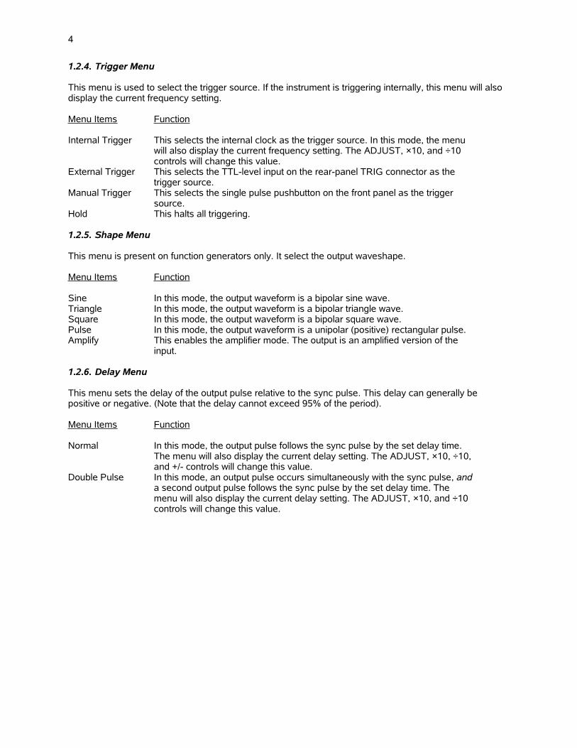
1.2.4. Trigger Menu
This menu is used to select the trigger source. If the instrument is triggering internally, this menu will also display the current frequency setting.
Menu Items Function
Internal Trigger This selects the internal clock as the trigger source. In this mode, the menu will also display the current frequency setting. The ADJUST, ×10, and ÷10 controls will change this value.
External Trigger This selects the TTL-level input on the rear-panel TRIG connector as the trigger source.
Manual Trigger This selects the single pulse pushbutton on the front panel as the trigger source.
Hold This halts all triggering.
1.2.5. Shape Menu
This menu is present on function generators only. It select the output waveshape.
Menu Items Function
Sine In this mode, the output waveform is a bipolar sine wave.Triangle In this mode, the output waveform is a bipolar triangle wave.Square In this mode, the output waveform is a bipolar square wave.Pulse In this mode, the output waveform is a unipolar (positive) rectangular pulse.Amplify This enables the amplifier mode. The output is an amplified version of the
input.
1.2.6. Delay Menu
This menu sets the delay of the output pulse relative to the sync pulse. This delay can generally be positive or negative. (Note that the delay cannot exceed 95% of the period).
Menu Items Function
Normal In this mode, the output pulse follows the sync pulse by the set delay time. The menu will also display the current delay setting. The ADJUST, ×10, ÷10, and +/- controls will change this value.
Double Pulse In this mode, an output pulse occurs simultaneously with the sync pulse, and a second output pulse follows the sync pulse by the set delay time. The menu will also display the current delay setting. The ADJUST, ×10, and ÷10 controls will change this value.

5
1.2.7. Pulse Width Menu
This menu controls the pulse width of the output pulse.
Menu Items Function
Normal In this mode, the pulse width is controlled directly, and is held constant when the frequency changes. The menu will display the current pulse width setting.The ADJUST, ×10, and ÷10 controls will change this value.
Duty cycle In this mode, the duty cycle is controlled directly, and is held constant when the frequency changes. The menu will display the current duty cycle setting. The ADJUST, ×10, and ÷10 controls will change this value. This mode is onlyapplicable when triggering internally.
DC output This mode sets the output pulse width to DC (i.e., infinite), if the instrument supports this feature.
PWIN=PWOUT This mode is used only when triggering externally. It allows the output pulse width to track the pulse width of the external trigger signal.
Ext Control If your instrument has a rear-panel “PW” or “EW” connector, and this mode isactivated, the pulse width can be controlled by an external voltage applied to this connector. 0V will set the pulse width to its minimum value, and +10V willset it to its maximum value.
1.2.8. Rise Time (TR) Menu
This menu controls the rise time of the output pulse, on instruments that support this feature.
1.2.9. Amplitude Menu
This menu controls the output amplitude.
Menu Items Function
Normal In this mode, the amplitude is controlled directly. The menu will display the current amplitude setting. The ADJUST, ×10, and ÷10 controls will change this value.
Ext Control If your instrument has a rear-panel “AMP” or “EA” connector, and this mode is activated, the amplitude can be controlled by an external voltage applied tothis connector. 0V will set the amplitude to its minimum value, and +10V will set it to its maximum value.
Ext Amplify In this mode, the output signal is an amplified replica of the signal on one of the input connectors. This feature is not present on all instruments.
1.2.10. Offset Menu
This menu controls the output offset, if the instrument supports this feature. The ADJUST, ×10, and ÷10 controls will change this value. Certain instruments allow the offset to be controlled by an external DC voltage. For these instruments, these control options are presented:
Menu Items Function
Normal In this mode, the offset is controlled directly. The menu will display the current offset setting. The ADJUST, ×10, and ÷10 controls will change this value.
External control If your instrument has a rear-panel “EO” connector, and this mode is activated, the offset can be controlled by an external DC voltage applied to this connector. 0V will set the offset to its minimum value, and +10V will set it to its maximum value.
6
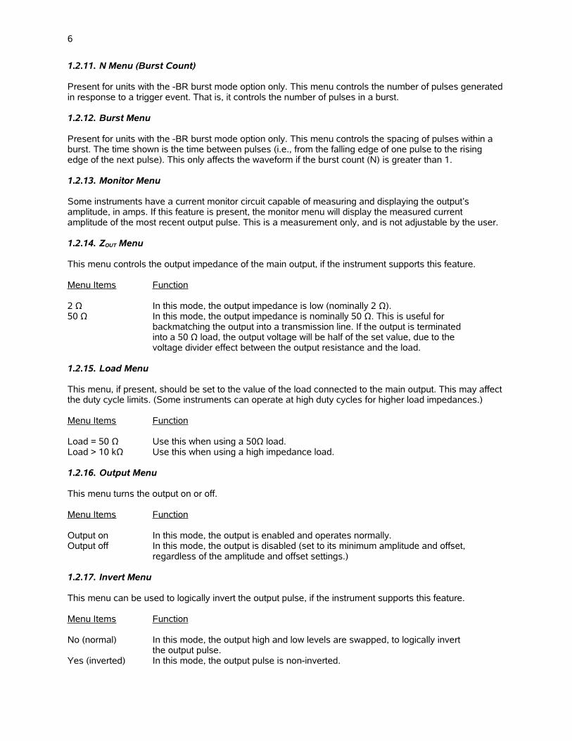
1.2.11. N Menu (Burst Count)
Present for units with the -BR burst mode option only. This menu controls the number of pulses generatedin response to a trigger event. That is, it controls the number of pulses in a burst.
1.2.12. Burst Menu
Present for units with the -BR burst mode option only. This menu controls the spacing of pulses within a burst. The time shown is the time between pulses (i.e., from the falling edge of one pulse to the rising edge of the next pulse). This only affects the waveform if the burst count (N) is greater than 1.
1.2.13. Monitor Menu
Some instruments have a current monitor circuit capable of measuring and displaying the output’s amplitude, in amps. If this feature is present, the monitor menu will display the measured current amplitude of the most recent output pulse. This is a measurement only, and is not adjustable by the user.
1.2.14. ZOUT Menu
This menu controls the output impedance of the main output, if the instrument supports this feature.
Menu Items Function
2 Ω In this mode, the output impedance is low (nominally 2 Ω).50 Ω In this mode, the output impedance is nominally 50 Ω. This is useful for
backmatching the output into a transmission line. If the output is terminated into a 50 Ω load, the output voltage will be half of the set value, due to the voltage divider effect between the output resistance and the load.
1.2.15. Load Menu
This menu, if present, should be set to the value of the load connected to the main output. This may affect the duty cycle limits. (Some instruments can operate at high duty cycles for higher load impedances.)
Menu Items Function
Load = 50 Ω Use this when using a 50Ω load.Load > 10 kΩ Use this when using a high impedance load.
1.2.16. Output Menu
This menu turns the output on or off.
Menu Items Function
Output on In this mode, the output is enabled and operates normally.Output off In this mode, the output is disabled (set to its minimum amplitude and offset,
regardless of the amplitude and offset settings.)
1.2.17. Invert Menu
This menu can be used to logically invert the output pulse, if the instrument supports this feature.
Menu Items Function
No (normal) In this mode, the output high and low levels are swapped, to logically invert the output pulse.
Yes (inverted) In this mode, the output pulse is non-inverted.
7
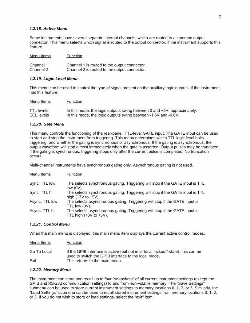
1.2.18. Active Menu
Some instruments have several separate internal channels, which are routed to a common output connector. This menu selects which signal is routed to the output connector, if the instrument supports thisfeature.
Menu Items Function
Channel 1 Channel 1 is routed to the output connector.Channel 2 Channel 2 is routed to the output connector.
1.2.19. Logic Level Menu
This menu can be used to control the type of signal present on the auxiliary logic outputs, if the instrumenthas this feature.
Menu Items Function
TTL levels In this mode, the logic outputs swing between 0 and +5V, approximately.ECL levels In this mode, the logic outputs swing between -1.6V and -0.8V.
1.2.20. Gate Menu
This menu controls the functioning of the rear-panel, TTL-level GATE input. The GATE input can be used to start and stop the instrument from triggering. This menu determines which TTL logic level halts triggering, and whether the gating is synchronous or asynchronous. If the gating is asynchronous, the output waveform will stop almost immediately when the gate is asserted. Output pulses may be truncated. If the gating is synchronous, triggering stops only after the current pulse is completed. No truncation occurs.
Multi-channel instruments have synchronous gating only. Asynchronous gating is not used.
Menu Items Function
Sync, TTL low The selects synchronous gating. Triggering will stop if the GATE input is TTL low (0V).
Sync, TTL hi The selects synchronous gating. Triggering will stop if the GATE input is TTL high (+3V to +5V).
Async, TTL low The selects asynchronous gating. Triggering will stop if the GATE input is TTL low (0V).
Async, TTL hi The selects asynchronous gating. Triggering will stop if the GATE input is TTL high (+3V to +5V).
1.2.21. Control Menu
When the main menu is displayed, this main menu item displays the current active control modes.
Menu Items Function
Go To Local If the GPIB interface is active (but not in a “local lockout” state), this can be used to switch the GPIB interface to the local mode.
Exit This returns to the main menu.
1.2.22. Memory Menu
The instrument can store and recall up to four "snapshots" of all current instrument settings (except the GPIB and RS-232 communication settings) to and from non-volatile memory. The "Save Settings" submenu can be used to store current instrument settings to memory locations 0, 1, 2, or 3. Similarly, the "Load Settings" submenu can be used to recall stored instrument settings from memory locations 0, 1, 2, or 3. If you do not wish to store or load settings, select the "exit" item.
8
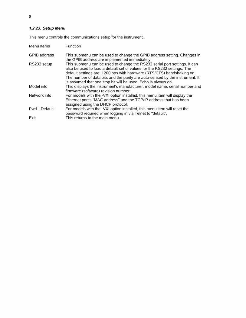
1.2.23. Setup Menu
This menu controls the communications setup for the instrument.
Menu Items Function
GPIB address This submenu can be used to change the GPIB address setting. Changes in the GPIB address are implemented immediately.
RS232 setup This submenu can be used to change the RS232 serial port settings. It can also be used to load a default set of values for the RS232 settings. The default settings are: 1200 bps with hardware (RTS/CTS) handshaking on. The number of data bits and the parity are auto-sensed by the instrument. It is assumed that one stop bit will be used. Echo is always on.
Model info This displays the instrument's manufacturer, model name, serial number and firmware (software) revision number.
Network info For models with the -VXI option installed, this menu item will display the Ethernet port's “MAC address” and the TCP/IP address that has been assigned using the DHCP protocol.
Pwd→Default For models with the -VXI option installed, this menu item will reset the password required when logging in via Telnet to “default”.
Exit This returns to the main menu.

9
1.3. Introduction to the RS-232 Serial Bus
1.3.1. Introduction
Most personal computers have at least one RS-232 serial port. This can be used to control the Avtech instrument. The RS-232 port allows a single, point-to-point connection between the computer and the instrument. That is, the computer port can only be attached to one instrument at a time. This connection scheme is illustrated below:
The computer is connected with a RS-232 "straight-through" cable. This cable is available at most computer stores, and it is the same type of cable that is generally used to connect a PC to an external modem. Beware that newer PCs generally have 9-pin male RS-232 connectors, whereas older computers generally have 25-pin male RS-232 connectors. The actual cable wiring connections are described in the "Cable Connections" section.
The RS-232 port can be used to communicate at speeds of 1200, 2400, 4800, 9600, 19200, 38400, 57600, or 115200 bits per second.
1.3.2. RS-232 Communications Settings
The RS-232 serial port has numerous settings associated with it. These must be set to the appropriate values on both the computer (in your terminal software) and the pulse generator in order for the two to communicate properly. On the pulse generator, these settings can be adjusted locally from the front panel,or by using the SYSTem:COMMunicate:SERial family of remote commands. These settings are:
1. Baud rate . This is the communication speed setting. The instrument can communicate at 1200, 2400, 4800, 9600, 19200, 38400, 57600, or 115200 bits per second (also called baud).
2. Handshaking . The instrument can either use hardware handshaking (also called RTS/CTS handshaking) or no handshaking to synchronize data transfer. Hardware handshaking is more reliablethan no handshaking, since it ensures that the input buffer will not overflow. (The RS-232 input buffer is 512 bytes long.)
The number of data bits and the parity are auto-sensed by the instrument. It is assumed that one stop bit will be used. Echo is always on.
One of the front-panel submenu commands allows the user to set the RS232 parameters to their default settings. These are: 1200 bps with hardware handshaking on.
COMPUTER WITHRS-232 SERIAL PORT
PULSE GENERATOR
RS-232“STRAIGHT-THROUGH
CABLE
10
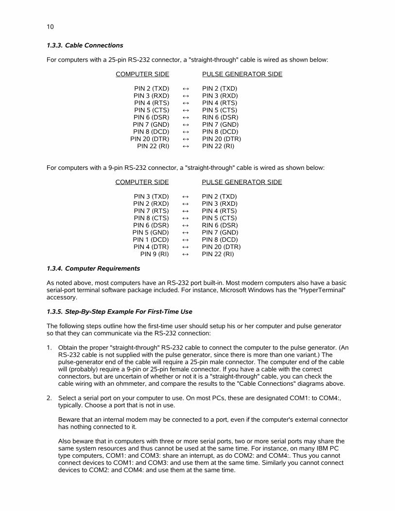
1.3.3. Cable Connections
For computers with a 25-pin RS-232 connector, a "straight-through" cable is wired as shown below:
COMPUTER SIDE PULSE GENERATOR SIDE
PIN 2 (TXD) ↔ PIN 2 (TXD)PIN 3 (RXD) ↔ PIN 3 (RXD)PIN 4 (RTS) ↔ PIN 4 (RTS)PIN 5 (CTS) ↔ PIN 5 (CTS)PIN 6 (DSR) ↔ RIN 6 (DSR)PIN 7 (GND) ↔ PIN 7 (GND)PIN 8 (DCD) ↔ PIN 8 (DCD)
PIN 20 (DTR) ↔ PIN 20 (DTR)PIN 22 (RI) ↔ PIN 22 (RI)
For computers with a 9-pin RS-232 connector, a "straight-through" cable is wired as shown below:
COMPUTER SIDE PULSE GENERATOR SIDE
PIN 3 (TXD) ↔ PIN 2 (TXD)PIN 2 (RXD) ↔ PIN 3 (RXD)PIN 7 (RTS) ↔ PIN 4 (RTS)PIN 8 (CTS) ↔ PIN 5 (CTS)PIN 6 (DSR) ↔ RIN 6 (DSR)PIN 5 (GND) ↔ PIN 7 (GND)PIN 1 (DCD) ↔ PIN 8 (DCD)PIN 4 (DTR) ↔ PIN 20 (DTR)
PIN 9 (RI) ↔ PIN 22 (RI)
1.3.4. Computer Requirements
As noted above, most computers have an RS-232 port built-in. Most modern computers also have a basic serial-port terminal software package included. For instance, Microsoft Windows has the "HyperTerminal" accessory.
1.3.5. Step-By-Step Example For First-Time Use
The following steps outline how the first-time user should setup his or her computer and pulse generator so that they can communicate via the RS-232 connection:
1. Obtain the proper "straight-through" RS-232 cable to connect the computer to the pulse generator. (AnRS-232 cable is not supplied with the pulse generator, since there is more than one variant.) The pulse-generator end of the cable will require a 25-pin male connector. The computer end of the cable will (probably) require a 9-pin or 25-pin female connector. If you have a cable with the correct connectors, but are uncertain of whether or not it is a "straight-through" cable, you can check the cable wiring with an ohmmeter, and compare the results to the "Cable Connections" diagrams above.
2. Select a serial port on your computer to use. On most PCs, these are designated COM1: to COM4:, typically. Choose a port that is not in use.
Beware that an internal modem may be connected to a port, even if the computer's external connectorhas nothing connected to it.
Also beware that in computers with three or more serial ports, two or more serial ports may share the same system resources and thus cannot be used at the same time. For instance, on many IBM PC type computers, COM1: and COM3: share an interrupt, as do COM2: and COM4:. Thus you cannot connect devices to COM1: and COM3: and use them at the same time. Similarly you cannot connect devices to COM2: and COM4: and use them at the same time.
11
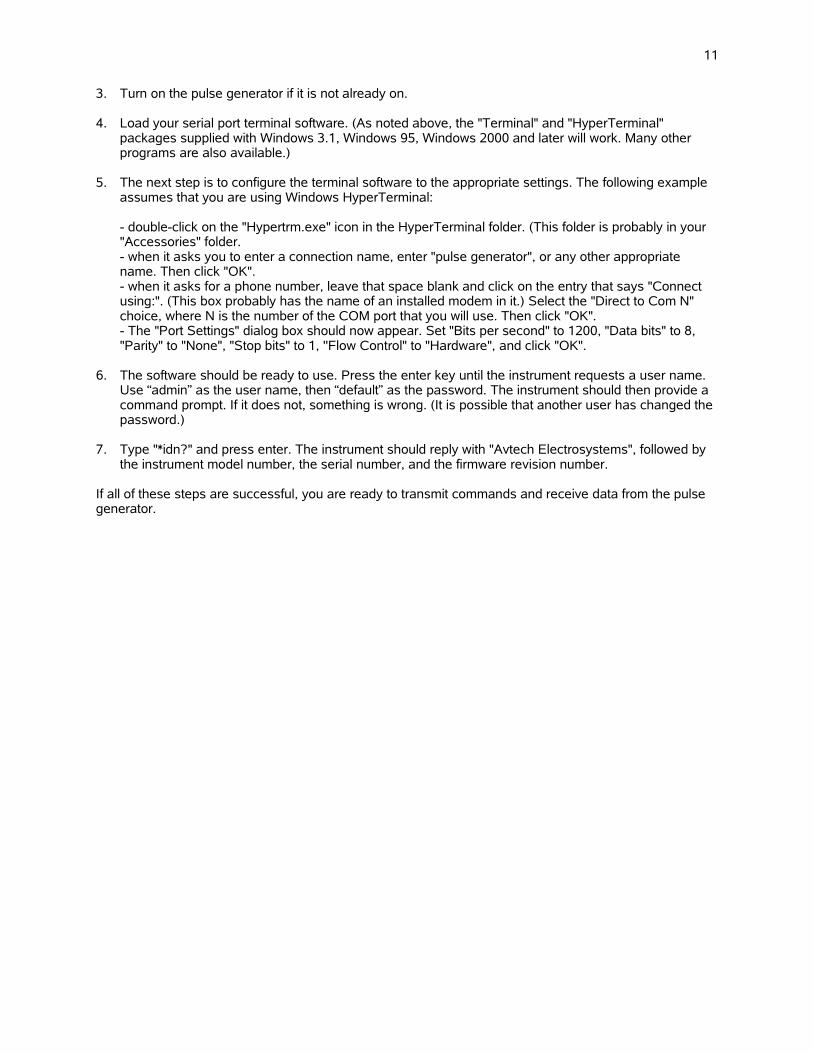
3. Turn on the pulse generator if it is not already on.
4. Load your serial port terminal software. (As noted above, the "Terminal" and "HyperTerminal" packages supplied with Windows 3.1, Windows 95, Windows 2000 and later will work. Many other programs are also available.)
5. The next step is to configure the terminal software to the appropriate settings. The following example assumes that you are using Windows HyperTerminal:
- double-click on the "Hypertrm.exe" icon in the HyperTerminal folder. (This folder is probably in your "Accessories" folder.- when it asks you to enter a connection name, enter "pulse generator", or any other appropriate name. Then click "OK".- when it asks for a phone number, leave that space blank and click on the entry that says "Connect using:". (This box probably has the name of an installed modem in it.) Select the "Direct to Com N" choice, where N is the number of the COM port that you will use. Then click "OK".- The "Port Settings" dialog box should now appear. Set "Bits per second" to 1200, "Data bits" to 8, "Parity" to "None", "Stop bits" to 1, ''Flow Control" to "Hardware", and click "OK".
6. The software should be ready to use. Press the enter key until the instrument requests a user name. Use “admin” as the user name, then “default” as the password. The instrument should then provide a command prompt. If it does not, something is wrong. (It is possible that another user has changed the password.)
7. Type "*idn?" and press enter. The instrument should reply with "Avtech Electrosystems", followed by the instrument model number, the serial number, and the firmware revision number.
If all of these steps are successful, you are ready to transmit commands and receive data from the pulse generator.

12
1.4. Introduction to the GPIB IEEE-488.2 Bus
1.4.1. Introduction
The General Purpose Interface Bus (GPIB) is an interface specifically designed for interconnecting electronic test equipment and computers. This bus has been standardized by the IEEE under standards IEEE-488.1 (related to hardware) and IEEE-488.2 (relating to software). (An instrument which complies with IEEE-488.2 automatically complies with IEEE-488.1.)
The GPIB is much more flexible than the RS-232 control method. Up to 15 devices can be connected simultaneously to the GPIB. The devices can be connected in a linear or star fashion, or any combination of linear and star, as illustrated below:
More than one computer controller can be present on the bus, if desired. Each device on the bus has its own address, in the range of 0 to 30.
When using the GPIB, these rules should be followed:
1. Each instrument (including controllers) must have its own address, in the range of 0-30.2. Do not connect more than 15 devices to the GPIB.3. The maximum cabling length should be limited to (2 meters) × (the number of devices), or 20 meters,
whichever is less.4. At least two-thirds of the devices must be turned-on for the GPIB to be used.5. Connect the devices in a linear or star configuration as shown above. Do not use loop or parallel
connections.
The standard GPIB cable connector is designed to be stackable, so that any number of cables can connect to the same point.
1.4.2. Controller and Cabling Requirements
To use a personal computer as a GPIB controller, a GPIB controller board and its associated software must be installed in the computer. (Unlike the RS-232 port, they are not usually included in computers when purchased.) The largest, and recommended, manufacturer of controller boards is National Instruments (http://www.ni.com/). National Instruments also sells the necessary cabling. L-Com is also a good source for cables, (http://www.L-com.com/) and sells a wider variety of cables than National Instruments.
1.4.3. Step-By-Step Example For First-Time Use
The following steps outline how the first-time user should setup his or her computer and pulse generator so that they can communicate via the GPIB bus:
INSTRUMENTS WITHGPIB INTERFACES
GPIBCABLE
COMPUTER WITHGPIB CONTROLLER CARD
13
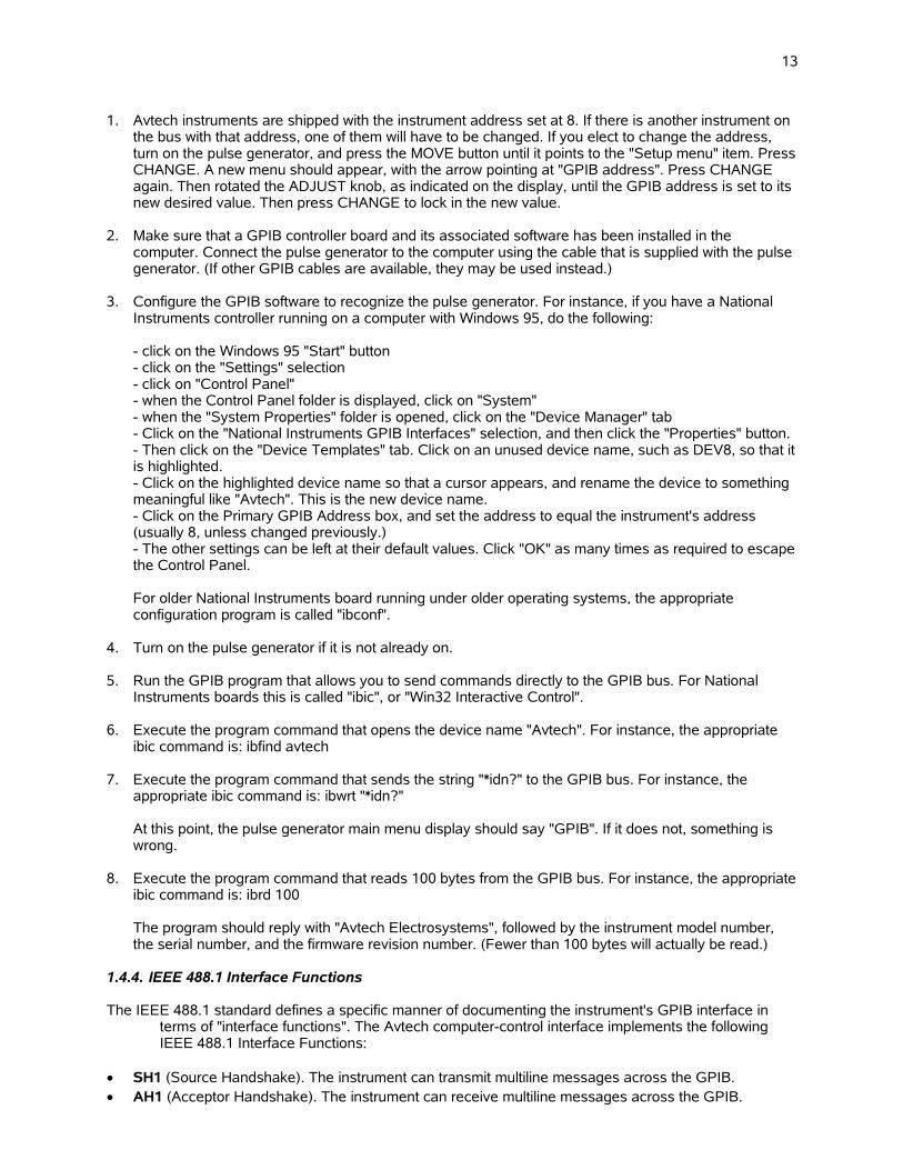
1. Avtech instruments are shipped with the instrument address set at 8. If there is another instrument on the bus with that address, one of them will have to be changed. If you elect to change the address, turn on the pulse generator, and press the MOVE button until it points to the "Setup menu" item. PressCHANGE. A new menu should appear, with the arrow pointing at "GPIB address". Press CHANGE again. Then rotated the ADJUST knob, as indicated on the display, until the GPIB address is set to its new desired value. Then press CHANGE to lock in the new value.
2. Make sure that a GPIB controller board and its associated software has been installed in the computer. Connect the pulse generator to the computer using the cable that is supplied with the pulse generator. (If other GPIB cables are available, they may be used instead.)
3. Configure the GPIB software to recognize the pulse generator. For instance, if you have a National Instruments controller running on a computer with Windows 95, do the following:
- click on the Windows 95 "Start" button- click on the "Settings" selection- click on "Control Panel"- when the Control Panel folder is displayed, click on "System"- when the "System Properties" folder is opened, click on the "Device Manager" tab- Click on the "National Instruments GPIB Interfaces" selection, and then click the "Properties" button. - Then click on the "Device Templates" tab. Click on an unused device name, such as DEV8, so that itis highlighted.- Click on the highlighted device name so that a cursor appears, and rename the device to something meaningful like "Avtech". This is the new device name. - Click on the Primary GPIB Address box, and set the address to equal the instrument's address (usually 8, unless changed previously.)- The other settings can be left at their default values. Click "OK" as many times as required to escapethe Control Panel.
For older National Instruments board running under older operating systems, the appropriate configuration program is called "ibconf".
4. Turn on the pulse generator if it is not already on.
5. Run the GPIB program that allows you to send commands directly to the GPIB bus. For National Instruments boards this is called "ibic", or "Win32 Interactive Control".
6. Execute the program command that opens the device name "Avtech". For instance, the appropriate ibic command is: ibfind avtech
7. Execute the program command that sends the string "*idn?" to the GPIB bus. For instance, the appropriate ibic command is: ibwrt "*idn?"
At this point, the pulse generator main menu display should say "GPIB". If it does not, something is wrong.
8. Execute the program command that reads 100 bytes from the GPIB bus. For instance, the appropriateibic command is: ibrd 100
The program should reply with "Avtech Electrosystems", followed by the instrument model number, the serial number, and the firmware revision number. (Fewer than 100 bytes will actually be read.)
1.4.4. IEEE 488.1 Interface Functions
The IEEE 488.1 standard defines a specific manner of documenting the instrument's GPIB interface in terms of "interface functions". The Avtech computer-control interface implements the following IEEE 488.1 Interface Functions:
SH1 (Source Handshake). The instrument can transmit multiline messages across the GPIB. AH1 (Acceptor Handshake). The instrument can receive multiline messages across the GPIB.

14
T6 (Talker). The instrument becomes a talker when the controller sends its talk address with the ATN (attention) line asserted. It can respond to a serial poll. It ceases to be a talker when the controller sends another device's talk address with ATN asserted. The instrument does not have talk-only capability.
L4 (Listener). The instrument becomes a listener when the controller sends its listen address with the ATN (attention) line asserted. The instrument does not have listen-only capability.
SR1 (Service Request). The instrument asserts the SRQ (Service Request) line to notify the controllerwhen it requires service.
RL1 (Remote Local). The instrument responds to both the GTL (Go To Local) and the LLO (Local Lockout) messages.
PP0 (Parallel Poll). The instrument has no parallel poll capability. DC1 (Device Clear). The instrument responds to the DCL (Device Clear) message, and when made a
listener, the SDC (Selected Device Clear) messages. DT0 (Device Trigger). The instrument has no device trigger capability. C0 (Controller). The instrument cannot control other devices. E2 (Electrical). Three-state drivers are used in the transceivers.
1.4.5. End-of-String (EOS) Issues
When a controller sends a message to a GPIB-connected instrument, such as an Avtech pulse generator, two methods can be used to indicate the end of the message.
The first, and most common, method is to assert the End-or-Identify (EOI) hardware signal on the GPIB cable. Most software does this automatically when sending messages, by default, so that the user doesn't need to worry about manually terminating the message.
If the software does not automatically use the EOI method, the user can manually add an End-of-String (EOS) character to terminate the message. The EOS character is the null character, ASCII code 0. This isnot a standard keyboard character, so the user will need to know the software-specific method of adding anull character to the message. With Windows-based National Instruments controllers, this is achieved by using a backslash followed by a zero, like so:
ibwrt "output on\0"
For HTBasic programming, you may need to append the “END” token to the command, like so:
OUTPUT 715;"OUTPUT ON",END
Other software packages will have different methods of adding an EOS character.
One or both of these messages must be used to terminate the message. If neither is used, the instrument will "freeze", as it waits for a termination message.
1.4.6. Other GPIB Notes
The size of the GPIB data buffer is 512 bytes. This buffer cannot overflow; the system interface will prevent further data transfer. (However, the maximum length of a single command message or a single compound command message that is to be parsed is 512 bytes. Longer messages will not be parsed properly and will generate an error.)
1.4.7. Debugging GPIB Problems
If you suspect that your GPIB controller and the attached instrument are not communicating properly, or that a particular sequence of commands is causing the attached instrument to act in an unexpected manner, there are two methods of observing the controller-instrument communications.
The first, and best, method is to use a GPIB analyzer device. Some premium controller boards have this feature built-in. They allow eavesdropping of the inter-device communications, right down to the level of watching the individual signal lines change. The National Instruments (www.ni.com) "AT-GPIB/TNT+", "PCMCIA-GPIB+", and "PCI-GPIB+" products are examples of controller/analyzers.

15
The second is to use a software utility, such as the National Instruments "NI-Spy" program. This program, or a similar one, is usually supplied with a GPIB controller card. This utility allows the user to view the software calls that are made to the controller card by the software on the computer. This will allow you to confirm that the commands are being sent in the order that you expect. Typically, however, they do not offer eavesdropping of the GPIB bus itself, so these utilities are less useful than a full analyzer device.
1.4.8. GPIB Troubleshooting Checklist
Most GPIB-related problems reported to Avtech are a result of EOS/EOI issues, as described in section 1.4.5. However, if this does not seem to be the problem, this checklist may be of assistance in debugging the problem, or in supplying useful information to Avtech technical support staff:
Is the problem random or repeatable?
Have you confirmed that you are using the correct GPIB address? The address that is assigned toan Avtech instrument may be viewed and changed from the front-panel "Setup" menu. Your software settings will need to match this address. When shipped from the factory, Avtech instruments are preset to address 8.
Do other GPIB-connected instruments work? If not, the controller may be improperly configured.
Have you tried another GPIB cable?
Is your cabling within the limits set by the IEEE-488.1 standard? The maximum permitted cable length is the lesser of 20 meters, or 2 meters multiplied by the number of attached instruments. Caution is advised if any distance between two adjacent instruments exceeds 4 meters.
If the instrument is "freezing up" after a command is sent, make sure that the proper message termination method is being used (EOI, EOS or both), as described in section 1.4.5.
Is the instrument responding to any commands at all? Is it failing after a particular command sequence?
Is your controller board IEEE-488.1-1987 and IEEE-488.2-1987 compliant, or was it designed based on earlier (obsolete) standards?
Is the front panel liquid-crystal display active or blank? If it is blank after start-up, that may be indicative of an internal power supply problem. Contact Avtech ([email protected]) in this case.
Have you tested the instrument with a different controller? Avtech uses Microsoft Windows-based computers with National Instruments (www.ni.com) controller cards in its development and testing facilities, so it would be helpful to know if a problem instrument has been tested at the user's facilities with similar a computer/controller combination. (Avtech instruments are configured and calibrated at the factory using the instrument's GPIB port.)
Does the instrument work if you send commands using the RS-232 serial port connection, insteadof the GPIB port?
Have you confirmed that your AC power supply is reasonably close to the nominal 120V or 240V values?
16
1.5. Introduction to the Ethernet Port
1.5.1. Introduction to the -VXI Option
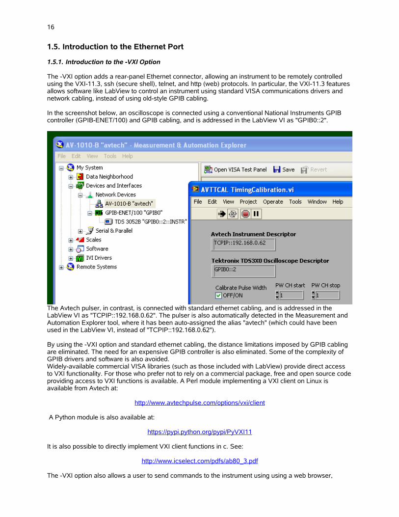
The -VXI option adds a rear-panel Ethernet connector, allowing an instrument to be remotely controlled using the VXI-11.3, ssh (secure shell), telnet, and http (web) protocols. In particular, the VXI-11.3 features allows software like LabView to control an instrument using standard VISA communications drivers and network cabling, instead of using old-style GPIB cabling.
In the screenshot below, an oscilloscope is connected using a conventional National Instruments GPIB controller (GPIB-ENET/100) and GPIB cabling, and is addressed in the LabView VI as "GPIB0::2".
The Avtech pulser, in contrast, is connected with standard ethernet cabling, and is addressed in the LabView VI as "TCPIP::192.168.0.62". The pulser is also automatically detected in the Measurement and Automation Explorer tool, where it has been auto-assigned the alias "avtech" (which could have been used in the LabView VI, instead of "TCPIP::192.168.0.62").
By using the -VXI option and standard ethernet cabling, the distance limitations imposed by GPIB cabling are eliminated. The need for an expensive GPIB controller is also eliminated. Some of the complexity of GPIB drivers and software is also avoided.Widely-available commercial VISA libraries (such as those included with LabView) provide direct access to VXI functionality. For those who prefer not to rely on a commercial package, free and open source codeproviding access to VXI functions is available. A Perl module implementing a VXI client on Linux is available from Avtech at:
http://www.avtechpulse.com/options/vxi/client
A Python module is also available at:
https://pypi.python.org/pypi/PyVXI11
It is also possible to directly implement VXI client functions in c. See:
http://www.icselect.com/pdfs/ab80_3.pdf
The -VXI option also allows a user to send commands to the instrument using using a web browser,

17
through a telnet session, or through a ssh (secure shell) session. Web browsers and telnet/ssh client programs are available for most modern operating systems.
The SCPI-compliant command set is the same as that used for GPIB and RS-232 control.
The -VXI option uses the Dynamic Host Configuration Protocol (DHCP) to obtain its network address. A DHCP server must be present on the local network for the -VXI option to operate properly.An example of a ssh session is shown below:
The instrument console is also accessible through any web browser with JavaScript and CSS support (most modern browsers include this). An example session, using the Firefox browser, is shown below:
1.5.2. IP Address Configuration
Every Ethernet device using the TCP/IP protocols has two addresses associated with it. The first “low-level” address is the “MAC address”, and it is normally expressed as twelve hexadecimal digits - for instance, 00:02:B3:BD:1A:82. This is assigned by the device manufacturer, and is not normally adjustable.The MAC address for your Avtech instrument can be viewed using the “Network Info” front-panel menu.
The second address is the IP address, which is normally expressed in “dotted decimal” notation - for instance, 192.168.0.97. Your Avtech instrument uses the Dynamic Host Configuration Protocol (DHCP) to obtain its network address (IP address). One (and only one) DHCP server must be present on the local network for the -VXI option to operate properly. Most “server” computers have DHCP server software.
18
DHCP servers normally assign new IP addresses randomly or sequentially from within an assigned range.This can lead to different IP addresses each time that your Avtech instrument is turned on. (The IP address for your Avtech instrument can be viewed using the “Network Info” front-panel menu.) However, most DHCP server software also allows address “reservations” to be made. That is, you tell the server to always offer a particular IP address to a device with a particular MAC address.
If a DHCP server is not present on your network, consider using an inexpensive firewall box from D-Link, Linksys, Netgear or others between the Avtech instrument and the network. These firewall devices typically include a DHCP server feature. The firewall can also be used to limit access to the Avtech instrument to appropriate sections of your network.
Because the Avtech instrument uses the DHCP protocol to obtain its address, there are no networking parameters to be configured from the instrument's front panel.
1.5.3. Security
When establishing a Telnet or ssh connection with the instrument, the instrument will request a username and a password. The username is “admin”, and the default password is “default”. The password can be changed using the “system:password:new” command. The username can not be changed.
This provides a minimal level of security. It is strongly recommended that a firewall device be placed between your LAN and other networks, to block Telnet transmissions from computers that you do not wishto have access to the instrument.
If your LAN is connected to the Internet, it is vitally important that the Telnet port (i.e., port 23) be blocked by a firewall device.
Lastly, please note that the Telnet protocol exchanges passwords “in the clear” - that is, without encryption. This makes it extra important to use a firewall device to limit Telnet exchanges to “trusted” areas of your network. Also, avoid using valuable passwords. If you wish to establish long-distance connections to control your instrument (over the public Internet, for instance), consider using “virtual private network (VPN)” devices to encrypt your communications, or establish “SSH port forwarding” between two computers on your networks. These techniques are beyond the scope of this manual, but they are common methods of providing safe communications over untrusted network links.
1.5.4. Web Console
The instrument console is also accessible through any web browser with JavaScript and CSS support (most modern browsers include this). Simple access the instrument through the normal web http protocol (on the standard port, 80), and a console session will be displayed in your browser. A username and password are required to log in (admin / default, as shipped from the factory).
1.5.5. Troubleshooting
The “Network Info” submenu will display the instruments MAC address and the IP address that has been assigned by the local DHCP server. If the IP address is not shown, the instrument was not successful in obtaining an IP address from a DHCP server at power-up. If this occurs, consult the logs of your DHCP server to locate error messages. (The MAC address of the instrument will typically be recorded in DHCP server logs - use this to locate relevant error messages.)
A DHCP server must be present on the local network for the -VXI option to operate properly. Your instrument attempts to contact the local DHCP server once at power-on. It will not attempt to re-contact the DHCP server in the event of failure. The instrument must be power-cycled to trigger another DHCP request, if the DHCP server was unavailable during the instrument's initial power-up period.
Because the Avtech instrument uses the DHCP protocol to obtain its address, there are no networking parameters to be configured from the instrument's front panel.

19
2. Programming Commands
2.1. Command Format
The instrument command set is based on the IEEE 488.2 and SCPI (Standard Commands for Programmable Instruments) industry standards.
The command set is based on a hierarchical "tree" structure, and command strings are formed by a seriesof keywords separated by colons. For instance, most of the commands for setting pulse parameters are under the "source:pulse" hierarchy. Examples of such commands are:
source:pulse:width 100nssource:pulse:delay 200ns
Some "nodes" in the hierarchy are default nodes, and do not need to be explicitly included in the command string. The "source" node is the default top-level node, so the above example commands can be shortened to
"pulse:width 100ns""pulse:delay 200ns"
Most keywords have a long form and a short form. The short forms of the above commands are:
"puls:widt 100ns""puls:del 200ns"
Only the long and short forms can be used. Other variants will generate an error.
When defining commands in this manual, default nodes will be indicated with square brackets "[]", and the keyword short forms will be denoted by upper-case letters. Numeric parameters will be referred to as <numeric value>, and boolean (i.e., "ON", "OFF", "0", or "1") parameters will be referred to as <boolean value>. The above two commands would then be referred to as:
[SOURce]:PULSe:WIDTh <numeric value>[SOURce]:PULSe:DELay <numeric value>
In some cases, a choice of keywords is available. This choice is indicated with a " | ". For instance, in the sequence:
[SOURce]:FREQuency:[CW | FIXed]
either CW or FIXed can be used.
2.1.1. Numeric Values
Commands that require a numeric parameter, such as the two discussed above, are flexible in the way that they handle numbers. Units and exponential notation can be used. For instance, the following commands can all be used to set the frequency to 1 kHz:
source:frequency 1000Hzsource:frequency 1 kHzsource:frequency 1000source:frequency 1e+3source:frequency 1e-3 MHz
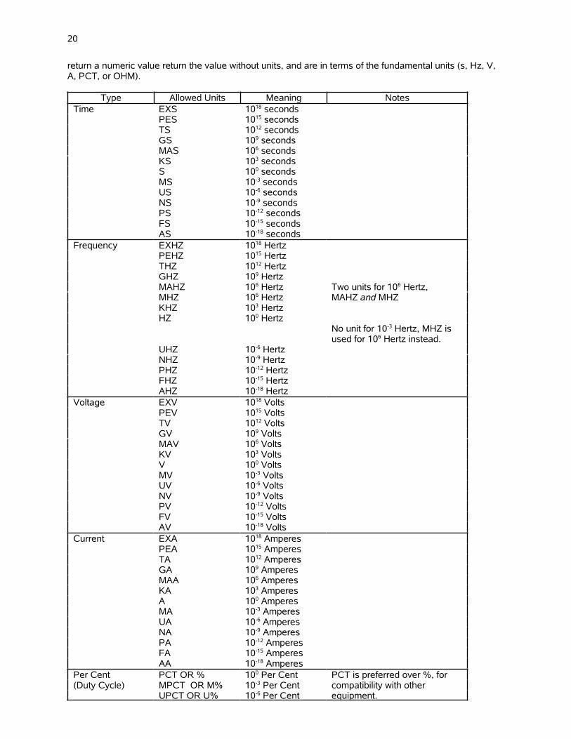
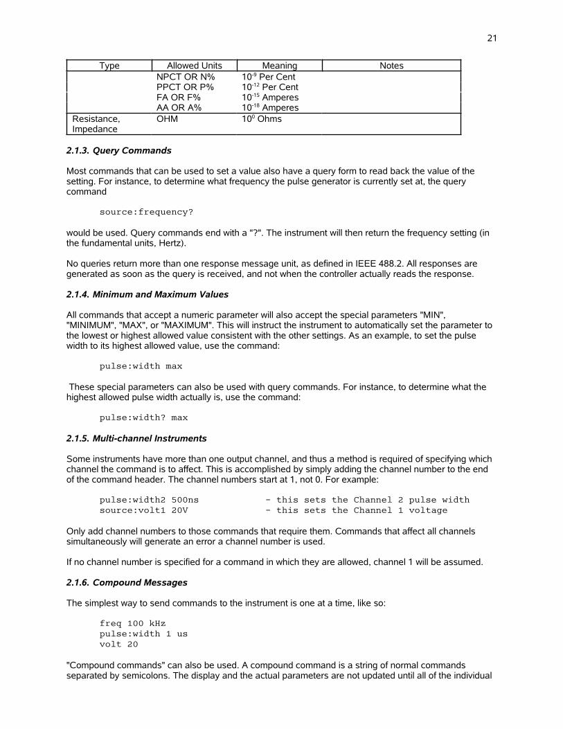
2.1.2. Units
The following table lists the units may be included as part of numeric values. (Any combination of upper case and lower case may be used; the parser is case-insensitive.) Numeric values without units are assumed to be in terms of the fundamental units (s, Hz, V, A, PCT, or OHM). All query commands which
20
return a numeric value return the value without units, and are in terms of the fundamental units (s, Hz, V, A, PCT, or OHM).
Type Allowed Units Meaning NotesTime EXS 1018 seconds
PES 1015 secondsTS 1012 secondsGS 109 secondsMAS 106 secondsKS 103 secondsS 100 secondsMS 10-3 secondsUS 10-6 secondsNS 10-9 secondsPS 10-12 secondsFS 10-15 secondsAS 10-18 seconds
Frequency EXHZ 1018 HertzPEHZ 1015 HertzTHZ 1012 HertzGHZ 109 HertzMAHZ 106 Hertz Two units for 106 Hertz,MHZ 106 Hertz MAHZ and MHZKHZ 103 HertzHZ 100 Hertz
No unit for 10-3 Hertz, MHZ isused for 106 Hertz instead.
UHZ 10-6 HertzNHZ 10-9 HertzPHZ 10-12 HertzFHZ 10-15 HertzAHZ 10-18 Hertz
Voltage EXV 1018 VoltsPEV 1015 VoltsTV 1012 VoltsGV 109 VoltsMAV 106 VoltsKV 103 VoltsV 100 VoltsMV 10-3 VoltsUV 10-6 VoltsNV 10-9 VoltsPV 10-12 VoltsFV 10-15 VoltsAV 10-18 Volts
Current EXA 1018 AmperesPEA 1015 AmperesTA 1012 AmperesGA 109 AmperesMAA 106 AmperesKA 103 AmperesA 100 AmperesMA 10-3 AmperesUA 10-6 AmperesNA 10-9 AmperesPA 10-12 AmperesFA 10-15 AmperesAA 10-18 Amperes
Per Cent PCT OR % 100 Per Cent PCT is preferred over %, for(Duty Cycle) MPCT OR M% 10-3 Per Cent compatibility with other
UPCT OR U% 10-6 Per Cent equipment.
21
Type Allowed Units Meaning NotesNPCT OR N% 10-9 Per CentPPCT OR P% 10-12 Per CentFA OR F% 10-15 AmperesAA OR A% 10-18 Amperes
Resistance,Impedance
OHM 100 Ohms
2.1.3. Query Commands
Most commands that can be used to set a value also have a query form to read back the value of the setting. For instance, to determine what frequency the pulse generator is currently set at, the query command
source:frequency?
would be used. Query commands end with a "?". The instrument will then return the frequency setting (in the fundamental units, Hertz).
No queries return more than one response message unit, as defined in IEEE 488.2. All responses are generated as soon as the query is received, and not when the controller actually reads the response.
2.1.4. Minimum and Maximum Values
All commands that accept a numeric parameter will also accept the special parameters "MIN", "MINIMUM", "MAX", or "MAXIMUM". This will instruct the instrument to automatically set the parameter to the lowest or highest allowed value consistent with the other settings. As an example, to set the pulse width to its highest allowed value, use the command:
pulse:width max
These special parameters can also be used with query commands. For instance, to determine what the highest allowed pulse width actually is, use the command:
pulse:width? max
2.1.5. Multi-channel Instruments
Some instruments have more than one output channel, and thus a method is required of specifying which channel the command is to affect. This is accomplished by simply adding the channel number to the end of the command header. The channel numbers start at 1, not 0. For example:
pulse:width2 500ns - this sets the Channel 2 pulse widthsource:volt1 20V - this sets the Channel 1 voltage
Only add channel numbers to those commands that require them. Commands that affect all channels simultaneously will generate an error a channel number is used.
If no channel number is specified for a command in which they are allowed, channel 1 will be assumed.
2.1.6. Compound Messages
The simplest way to send commands to the instrument is one at a time, like so:
freq 100 kHzpulse:width 1 usvolt 20
"Compound commands" can also be used. A compound command is a string of normal commands separated by semicolons. The display and the actual parameters are not updated until all of the individual
22
commands in the compound command have been received, which reduces overhead time. An example of a compound command is:
sour:pulse:width 1us;delay 2us;double off
The first command in the compound message sets the "tree level" for the remaining individual commands. For instance, the tree level of the first command in the above example is "sour:pulse". The remaining commands are assumed to be of the same tree level, so the instrument actually interprets the second and third commands as "sour:pulse:delay 2us" and "sour:puls:double off". Adding the tree level to the second and third commands manually would have generated an error. For instance, this is not a legal compound command:
sour:pulse:width 1us;sour:pulse:delay 2us;sour:pulse:double off
The tree level set by the first command may be temporarily overridden within the compound command by adding a colon in front of the individual command in question. For instance:
sour:pulse:width 1us;:source:volt 10;delay 2us;double off
is allowed, even though "source:volt" is not part of the "sour:puls" hierarchy. The semicolon does not affectthe last two commands since it is a temporary override.
Commands in the IEEE 488.2 common command hierarchy (which start with an asterisk) automatically temporarily override the tree level, and can be included in a compound command at any point. For instance:
sour:pulse:width 1us;*rst;delay 2us;double off
is allowed.
2.1.7. Maximum Command Lengths
The maximum length of a single command message or a single compound command message that is to be parsed is 512 bytes. Longer messages will not be parsed properly and will generate an error.
Within this limitation, numeric parameters can be of any length. They will be rounded off to the precision ofthe internal software.
2.1.8. Command Execution Order and Coupled Commands
All commands are executed in the order that they are received. All commands are executed sequentially. That is, no new commands are executed until the current command is finished.
Because of this, care must be taken when sending multiple commands to the instrument, so that no limits are exceeded between commands. For instance, consider the example of a pulse generator with a duty cycle limit of 20%. If the frequency is set at 1 kHz, and the pulse width is 100 us, the duty cycle is 10%. If the user then wishes to change the pulse width to 1ms, and the frequency to 100 Hz (again 10% duty cycle) the frequency must be lowered first, and then the pulse width increased. If the pulse width is increased first, the settings immediately afterwards would be 1 kHz and 1ms, giving 100% duty cycle and an error. The pulse generator would recognize this error and would not change the pulse width.
This particular problem can be avoided by using the [SOURce]:PULSe:HOLD DCYCle command, to hold the duty cycle constant during frequency changes.
Another potential coupling problem arises in pulse generators with an offset capability. If the amplitude and offset are both to be changed, care must be taken not to exceed the maximum output voltage or current (i.e. maximum amplitude+offset) between commands.
2.1.9. Execution Speed
The time to execute a command is typically < 150 ms, in a single-channel instrument.
23
2.2. The CALIBRATION Command Hierarchy
This section describes the commands starting with the keyword "CALIBRATION”. These commands control the self-calibration functions of the instrument, if present.
2.2.1. Tree Structure:
Keyword Parameter Notes
CALibration::[ALL]:FREQuency
2.2.2. CALibration:[ALL]
This command starts the self-calibration process. This will take 5-15 minutes, typically. If the query form is used, a summary report will be generated at the end of the process.
Examples of valid commands are:
cal - This performs a self-calibration. No summary is returned. Calibration errors will be reported via the usual error-reporting mechanisms.
cal? - This performs a self-calibration, andreturns a summary report of the changes.
2.2.3. CALibration:FREQuency
Instruments with a self-calibration feature can be set to self-calibrate at power-up, at every Nth power-up. Examples of valid commands are:
cal:freq 5 - Perform the self-calibration routine every 5 power-ups.
Cal:freq? - Returns the current self-calibration frequency.
24
2.3. The DIAGNOSTIC Command Hierarchy
This section describes the commands starting with the keyword "DIAGNOSTIC”. These commands provide various calibration functions, and are infrequently used.
2.3.1. Tree Structure:
Keyword Parameter Notes
DIAGnostic::AMPLitude
:CALibration: <numeric value> [no query form]:MONitor
:CALibration: <numeric value> [no query form]:STEP <numeric value>
:OFFSet:CALibration <numeric value> [no query form]
2.3.2. DIAGnostic:AMPLitude:CALibration
This command can be used to calibrate the output amplitude, if the set amplitude value does not agree exactly with a measured value. To adjust the calibration, use this command and submit your measured value as the numeric parameter. The internal software will compare the measured value to the latest amplitude setting, and the internal calibration memory will then be adjusted appropriately.
Examples of valid commands are:
diag:ampl:cal 52 V - if the programmed amplitude is 50V, but the measured value is 52V, this command will adjust the calibration appropriately.
diag:ampl:cal 470 mA - if the programmed amplitude is 500 mA, but the measured value is 470 mA, this command will adjust the calibration appropriately.
This command does not have a query form.
2.3.3. DIAGnostic:MONitor:CALibration
This command can be used to calibrate the output current monitor, if the monitor readings do not agree exactly other measured values. This command is only useful on instrument that have the current monitor feature.
To adjust the monitor calibration, use this command and submit your measured value as the numeric parameter. The internal software will compare the measured value to the latest current monitor reading, and the internal calibration memory will then be adjusted appropriately.
Examples of valid commands are:
diag:mon:cal 5.2 A - if the monitor reading is 5.0A, but the measured value is 5.2A, this command will adjust the calibration appropriately.
In multi-channel instruments with current monitors, the current monitors are individually adjustable. Add the channel number to the end of the command header.
This command does not have a query form.

25
2.3.4. DIAGnostic:MONitor:STEP
Some pulsed-constant current generators have an output-current monitor feature, which displays the measured current amplitude on the front-panel display. The resolution, or step-size, of this readout can be adjusted, if desired. The step size can not be set smaller than 1/5000, or larger than 1/5, of the maximum amplitude that the instrument is capable of generating.
Examples of valid commands are:
diag:mon:step 5mA - the monitor will increment and decrementin 5 mA steps.
diag:mon:step? - returns the current step-size.
After power-up or the *RST command, this function defaults to the same setting as the last time the instrument was on.
In multi-channel instruments with current monitors, this command affects all current monitors simultaneously. The monitor step-sizes are not individually adjustable.
2.3.5. DIAGnostic:OFFSet:CALibration
For instruments with a DC offset feature, this command can be used to calibrate the output offset, if the set amplitude value does not agree exactly with a measured value. To adjust the calibration, use this command and submit your measured value as the numeric parameter. The internal software will compare the measured value to the latest amplitude setting, and the internal calibration memory will then be adjusted appropriately.
Examples of valid commands are:
diag:offset:cal 52 V - if the programmed offset is 50V, but themeasured value is 52V, this command will adjust the calibration appropriately.
diag:offset:cal 470 mA - if the programmed offset is 500 mA, but the measured value is 470 mA, this commandwill adjust the calibration appropriately.
This command does not have a query form.

26
2.4. The MEASURE Command Hierarchy
This section describes the commands starting with the keyword "OUTPUT". These commands set variousparameters related to the pulse generator output stage.
2.4.1. Tree Structure:
Keyword Parameter Notes
MEASure::AMPLitude? [query only]
2.4.2. MEASure:AMPLitude?
This command is only available on instruments with a computer-readable current monitor. It returns the amplitude, as measured by current monitor circuit.
This command has a query form only.
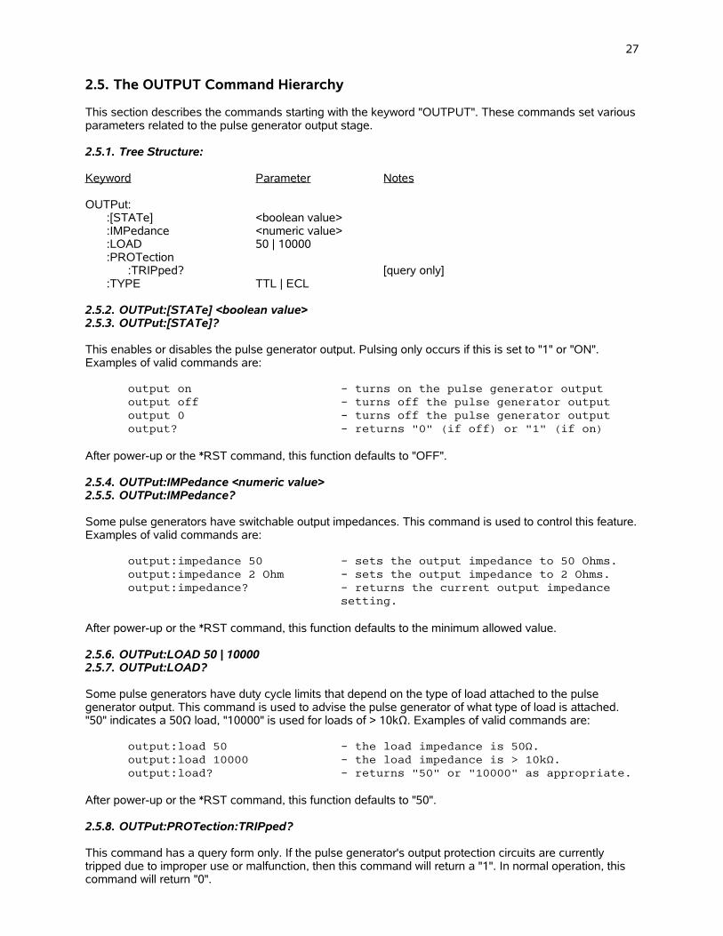
27
2.5. The OUTPUT Command Hierarchy
This section describes the commands starting with the keyword "OUTPUT". These commands set variousparameters related to the pulse generator output stage.
2.5.1. Tree Structure:
Keyword Parameter Notes
OUTPut::[STATe] <boolean value>:IMPedance <numeric value>:LOAD 50 | 10000:PROTection
:TRIPped? [query only]:TYPE TTL | ECL
2.5.2. OUTPut:[STATe] <boolean value> 2.5.3. OUTPut:[STATe]?
This enables or disables the pulse generator output. Pulsing only occurs if this is set to "1" or "ON". Examples of valid commands are:
output on - turns on the pulse generator outputoutput off - turns off the pulse generator outputoutput 0 - turns off the pulse generator outputoutput? - returns "0" (if off) or "1" (if on)
After power-up or the *RST command, this function defaults to "OFF".
2.5.4. OUTPut:IMPedance <numeric value> 2.5.5. OUTPut:IMPedance?
Some pulse generators have switchable output impedances. This command is used to control this feature.Examples of valid commands are:
output:impedance 50 - sets the output impedance to 50 Ohms.output:impedance 2 Ohm - sets the output impedance to 2 Ohms.output:impedance? - returns the current output impedance
setting.
After power-up or the *RST command, this function defaults to the minimum allowed value.
2.5.6. OUTPut:LOAD 50 | 10000 2.5.7. OUTPut:LOAD?
Some pulse generators have duty cycle limits that depend on the type of load attached to the pulse generator output. This command is used to advise the pulse generator of what type of load is attached. "50" indicates a 50Ω load, "10000" is used for loads of > 10kΩ. Examples of valid commands are:
output:load 50 - the load impedance is 50Ω.output:load 10000 - the load impedance is > 10kΩ.output:load? - returns "50" or "10000" as appropriate.
After power-up or the *RST command, this function defaults to "50".
2.5.8. OUTPut:PROTection:TRIPped?
This command has a query form only. If the pulse generator's output protection circuits are currently tripped due to improper use or malfunction, then this command will return a "1". In normal operation, this command will return "0".

28
2.5.9. OUTPut:TYPE TTL | ECL 2.5.10. OUTPut:TYPE?
Some pulse generators have auxiliary logic outputs, nominally synchronous with the main output, which can supply either TTL-level or ECL-level signals. (TTL levels are nominally 0V and +5V, ECL levels are nominally -1.6V and -0.8V.) This command is used to select the logic levels that are generated. Examples of valid commands are:
output:type ECL - the logic outputs provide ECL-level outputs.
output:type? - returns the current logic-level setting.
After power-up or the *RST command, this function defaults to TTL.
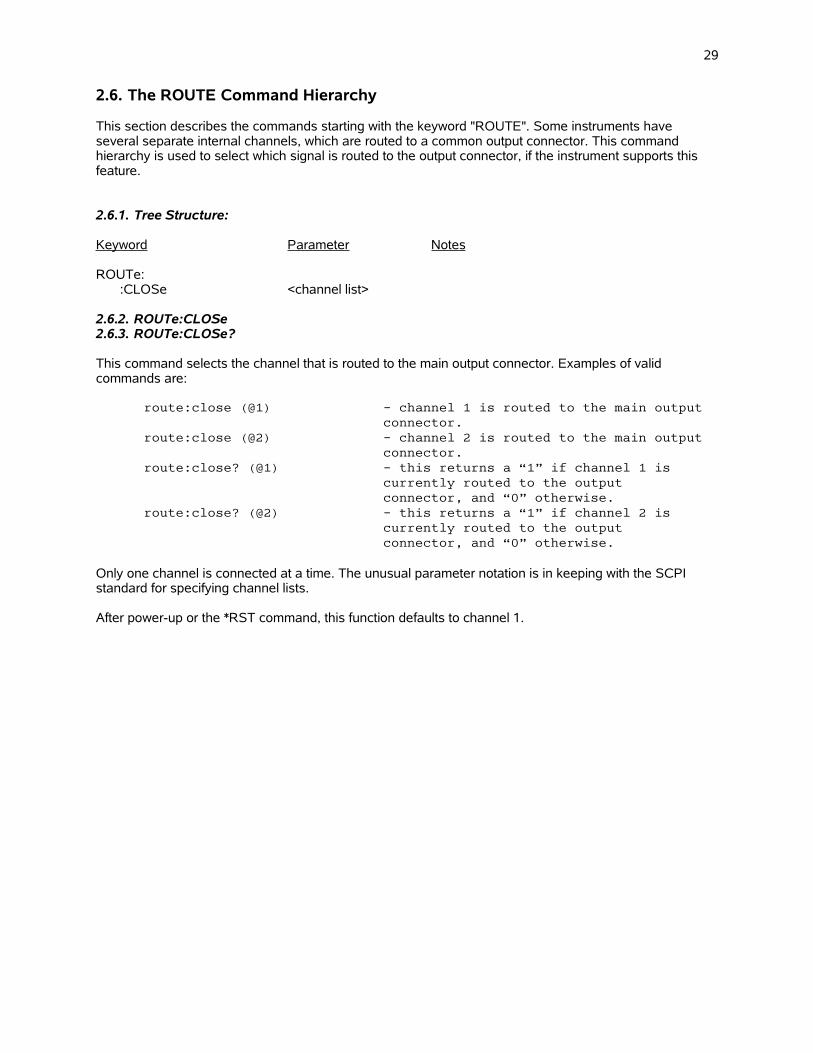
29
2.6. The ROUTE Command Hierarchy
This section describes the commands starting with the keyword "ROUTE". Some instruments have several separate internal channels, which are routed to a common output connector. This command hierarchy is used to select which signal is routed to the output connector, if the instrument supports this feature.
2.6.1. Tree Structure:
Keyword Parameter Notes
ROUTe::CLOSe <channel list>
2.6.2. ROUTe:CLOSe2.6.3. ROUTe:CLOSe?
This command selects the channel that is routed to the main output connector. Examples of valid commands are:
route:close (@1) - channel 1 is routed to the main output connector.
route:close (@2) - channel 2 is routed to the main output connector.
route:close? (@1) - this returns a “1” if channel 1 is currently routed to the output connector, and “0” otherwise.
route:close? (@2) - this returns a “1” if channel 2 is currently routed to the output connector, and “0” otherwise.
Only one channel is connected at a time. The unusual parameter notation is in keeping with the SCPI standard for specifying channel lists.
After power-up or the *RST command, this function defaults to channel 1.

30
2.7. The SOURCE:CURRENT Command Hierarchy
This section describes the commands starting with the keywords "[SOURce]:CURRent". The commands are only used if your pulse generator is a current pulser. (If it is a voltage pulser, see the SOURCE:VOLTAGE section.) This hierarchy is used primarily to set the output amplitude and offset.
2.7.1. Tree Structure:
Keyword Parameter Notes
[SOURce]::CURRent
[:LEVel][:IMMediate]
[:AMPLitude] <numeric value> | EXTernal | AMPLIFY:LOW <numeric value> | EXTernal
:PROTection:TRIPped? [query only]
2.7.2. [SOURce]:CURRent:[LEVel]:[IMMediate]:[AMPLitude] <numeric value> | EXTernal | AMPlify2.7.3. [SOURce]:CURRent:[LEVel]:[IMMediate]:[AMPLitude]?
This command is used to set or read the output current amplitude. Examples of valid commands are:
current 100A - sets output amplitude to 100Acurr 100mA - sets output amplitude to 100mAsource:curr 10 - sets output amplitude to 10Acurrent? - returns the output amplitude setting, in
amperes.
Some pulse generators allow the amplitude to be controlled by an external voltage applied to a connector on the rear panel of the instrument. This mode is enabled by using the "EXT" parameter:
source:current EXT - output amplitude is controlled by the external signal.
current external - output amplitude is controlled by the external signal.
Some pulse generators allow the instrument to act as an amplifier for one of the inputs. This mode is enabled by using the "AMP" parameter:
source:current AMP - sets amplifier mode.current amplify - sets amplifier mode.
After power-up or the *RST command, this function defaults to the minimum allowed value.
2.7.4. [SOURce]:CURRent:[LEVel]:[IMMediate]:LOW <numeric value> | EXTernal2.7.5. [SOURce]:CURRent:[LEVel]:[IMMediate]:LOW?
This command is used to set or read the output current offset, if the pulse generator has an offset capability. Examples of valid commands are:
current:low 100A - sets output amplitude offset to 100Acurr:low 100mA - sets output amplitude offset to 100mAsource:curr:low 10 - sets output amplitude offset to 10Acurrent:low? - returns the output amplitude offset
setting, in amperes.
Some pulse generators allow the offset to be controlled by an external voltage applied to a connector on the rear panel of the instrument. This mode is enabled by using the "EXT" parameter:

31
source:current:low EXT - output offset is controlled by the external signal.
Current:low external - output offset is controlled by the external signal.
After power-up or the *RST command, this function defaults to the minimum allowed value.
2.7.6. [SOURce]:CURRent:PROTection:TRIPped?
This command has a query form only. If the pulse generator's output protection circuits are currently tripped due to improper use or malfunction, then this command will return a "1". In normal operation, this command will return "0".

32
2.8. The SOURCE:FREQUENCY Command Hierarchy
This section describes the commands starting with the keywords "[SOURce]:FREQuency". These commands affect the frequency setting of the pulse generator (if the pulse generator has a variable internal clock).
2.8.1. Tree Structure:
Keyword Parameter Notes
[SOURce]::FREQuency
[:CW | FIXed] <numeric value>
2.8.2. [SOURce]:FREQuency:[CW | FIXed] <numeric value>2.8.3. [SOURce]:FREQuency:[CW | FIXed]?
This command is used to set or read the output pulse repetition frequency (PRF). Examples of valid commands are:
frequency 100 Hz - sets the frequency at 100 Hzfreq 1kHz - sets the frequency at 1 kHzsour:freq:fixed 200 - sets the frequency at 200 Hzfreq? - returns the current frequency setting
After power-up or the *RST command, this function defaults to the minimum allowed value.
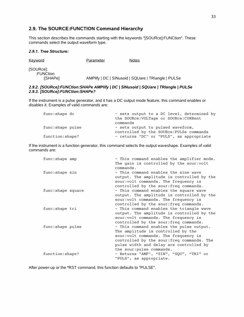
33
2.9. The SOURCE:FUNCTION Command Hierarchy
This section describes the commands starting with the keywords "[SOURce]:FUNCtion". These commands select the output waveform type.
2.9.1. Tree Structure:
Keyword Parameter Notes
[SOURce]::FUNCtion
:[SHAPe] AMPlify | DC | SINusoid | SQUare | TRIangle | PULSe
2.9.2. [SOURce]:FUNCtion:SHAPe AMPlify | DC | SINusoid | SQUare | TRIangle | PULSe2.9.3. [SOURce]:FUNCtion:SHAPe?
If the instrument is a pulse generator, and it has a DC output mode feature, this command enables or disables it. Examples of valid commands are:
func:shape dc - sets output to a DC level, determined bythe SOURce:VOLTage or SOURce:CURRent commands
func:shape pulse - sets output to pulsed waveform, controlled by the SOURce:PULSe commands
function:shape? - returns "DC" or "PULS", as appropriate
If the instrument is a function generator, this command selects the output waveshape. Examples of valid commands are:
func:shape amp - This command enables the amplifier mode.The gain is controlled by the sour:volt commands.
func:shape sin - This command enables the sine wave output. The amplitude is controlled by thesour:volt commands. The frequency is controlled by the sour:freq commands.
func:shape square - This command enables the square wave output. The amplitude is controlled by thesour:volt commands. The frequency is controlled by the sour:freq commands.
func:shape tri - This command enables the triangle wave output. The amplitude is controlled by thesour:volt commands. The frequency is controlled by the sour:freq commands.
func:shape pulse - This command enables the pulse output. The amplitude is controlled by the sour:volt commands. The frequency is controlled by the sour:freq commands. The pulse width and delay are controlled by the sour:pulse commands.
function:shape? - Returns "AMP", “SIN”, “SQU”, “TRI” or "PULS", as appropriate.
After power-up or the *RST command, this function defaults to "PULSE".
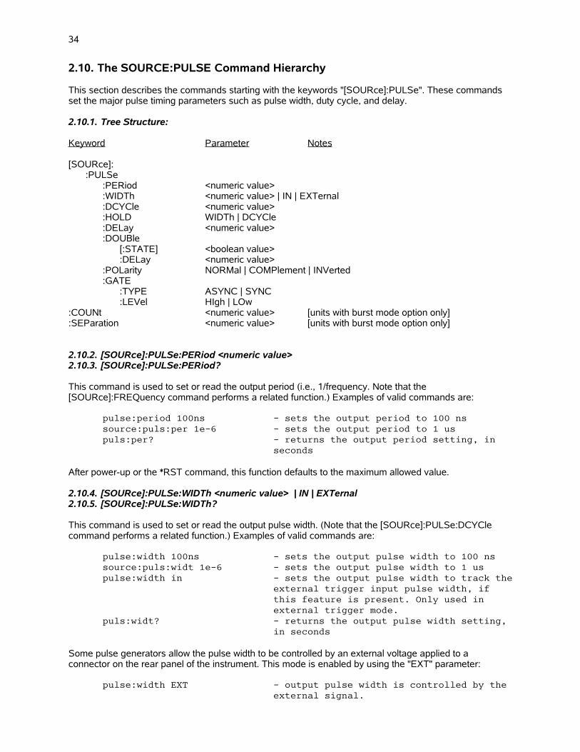
34
2.10. The SOURCE:PULSE Command Hierarchy
This section describes the commands starting with the keywords "[SOURce]:PULSe". These commands set the major pulse timing parameters such as pulse width, duty cycle, and delay.
2.10.1. Tree Structure:
Keyword Parameter Notes
[SOURce]::PULSe
:PERiod <numeric value>:WIDTh <numeric value> | IN | EXTernal:DCYCle <numeric value>:HOLD WIDTh | DCYCle:DELay <numeric value>:DOUBle
[:STATE] <boolean value>:DELay <numeric value>
:POLarity NORMal | COMPlement | INVerted:GATE
:TYPE ASYNC | SYNC:LEVel HIgh | LOw
:COUNt <numeric value> [units with burst mode option only]:SEParation <numeric value> [units with burst mode option only]
2.10.2. [SOURce]:PULSe:PERiod <numeric value>2.10.3. [SOURce]:PULSe:PERiod?
This command is used to set or read the output period (i.e., 1/frequency. Note that the [SOURce]:FREQuency command performs a related function.) Examples of valid commands are:
pulse:period 100ns - sets the output period to 100 nssource:puls:per 1e-6 - sets the output period to 1 uspuls:per? - returns the output period setting, in
seconds
After power-up or the *RST command, this function defaults to the maximum allowed value.
2.10.4. [SOURce]:PULSe:WIDTh <numeric value> | IN | EXTernal2.10.5. [SOURce]:PULSe:WIDTh?
This command is used to set or read the output pulse width. (Note that the [SOURce]:PULSe:DCYCle command performs a related function.) Examples of valid commands are:
pulse:width 100ns - sets the output pulse width to 100 nssource:puls:widt 1e-6 - sets the output pulse width to 1 uspulse:width in - sets the output pulse width to track the
external trigger input pulse width, if this feature is present. Only used in external trigger mode.
puls:widt? - returns the output pulse width setting, in seconds
Some pulse generators allow the pulse width to be controlled by an external voltage applied to a connector on the rear panel of the instrument. This mode is enabled by using the "EXT" parameter:
pulse:width EXT - output pulse width is controlled by the external signal.
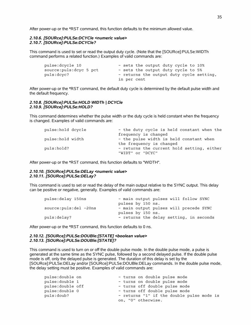
35
After power-up or the *RST command, this function defaults to the minimum allowed value.
2.10.6. [SOURce]:PULSe:DCYCle <numeric value>2.10.7. [SOURce]:PULSe:DCYCle?
This command is used to set or read the output duty cycle. (Note that the [SOURce]:PULSe:WIDTh command performs a related function.) Examples of valid commands are:
pulse:dcycle 10 - sets the output duty cycle to 10%source:puls:dcyc 5 pct - sets the output duty cycle to 5%puls:dcyc? - returns the output duty cycle setting,
in per cent
After power-up or the *RST command, the default duty cycle is determined by the default pulse width and the default frequency.
2.10.8. [SOURce]:PULSe:HOLD WIDTh | DCYCle2.10.9. [SOURce]:PULSe:HOLD?
This command determines whether the pulse width or the duty cycle is held constant when the frequency is changed. Examples of valid commands are:
pulse:hold dcycle - the duty cycle is held constant when thefrequency is changed
pulse:hold width - the pulse width is held constant when the frequency is changed
puls:hold? - returns the current hold setting, either"WIDT" or "DCYC"
After power-up or the *RST command, this function defaults to "WIDTH".
2.10.10. [SOURce]:PULSe:DELay <numeric value>2.10.11. [SOURce]:PULSe:DELay?
This command is used to set or read the delay of the main output relative to the SYNC output. This delay can be positive or negative, generally. Examples of valid commands are:
pulse:delay 150ns - main output pulses will follow SYNC pulses by 150 ns.
source:puls:del -20ns - main output pulses will precede SYNC pulses by 150 ns.
puls:delay? - returns the delay setting, in seconds
After power-up or the *RST command, this function defaults to 0 ns.
2.10.12. [SOURce]:PULSe:DOUBle:[STATE] <boolean value>2.10.13. [SOURce]:PULSe:DOUBle:[STATE]?
This command is used to turn on or off the double pulse mode. In the double pulse mode, a pulse is generated at the same time as the SYNC pulse, followed by a second delayed pulse. If the double pulse mode is off, only the delayed pulse is generated. The duration of this delay is set by the [SOURce]:PULSe:DELay and/or [SOURce]:PULSe:DOUBle:DELay commands. In the double pulse mode,the delay setting must be positive. Examples of valid commands are:
pulse:double on - turns on double pulse modepulse:double 1 - turns on double pulse modepulse:double off - turns off double pulse modepulse:double 0 - turns off double pulse modepuls:doub? - returns "1" if the double pulse mode is
on, "0" otherwise.

36
After power-up or the *RST command, this function defaults to "OFF".
2.10.14. [SOURce]:PULSe:DOUBle:DELay <numeric value>2.10.15. [SOURce]:PULSe:DOUBle:DELay?
This command performs the exactly the same function as the [SOURce]:PULSe:DELay command described previously.
2.10.16. [SOURce]:PULSe:POLarity NORMal | COMPlement | INVerted2.10.17. [SOURce]:PULSe:POLarity?
This command can be used to logically invert the output pulse on some models. That is, in the inverted mode (also called the complemented mode), the output high and low voltage levels are swapped. (The voltage polarity, positive or negative, does not change.) Examples of valid commands are:
pulse:polarity normal - sets normal modepulse:polarity inverted - inverts the output pulsepulse:polarity comp - inverts the output pulsepulse:pol? - returns "NORM" or "COMP" as appropriate.
After power-up or the *RST command, this function defaults to "NORMAL".
2.10.18. [SOURce]:PULSe:GATE:TYPE ASYNC | SYNC2.10.19. [SOURce]:PULSe:GATE:TYPE?
This command determines how the gate input functions. If the parameter is "ASYNC", the gate will act asynchronously of the output. That is, when the gate line is asserted the output waveform will stop immediately. Pulses may be truncated. If the "SYNC" parameter is chosen, triggering stops only after the current pulse is completed. No truncation occurs. Examples of valid commands are:
pulse:gate:type async - sets asynchronous (truncating) gatingpulse:gate:type sync - sets synchronous (non-truncating) gatingpulse:gate:type? - returns "ASYNC" or "SYNC" as appropriate
After power-up or the *RST command, this function defaults to "SYNC".
This command is not used with function generators.
2.10.20. [SOURce]:PULSe:GATE:LEVel HIgh|LOw2.10.21. [SOURce]:PULSe:GATE:LEVel?
This command determines how the gate input functions. If the parameter is "HI", the gate input will halt output triggering when the input is TTL HI (3-5V). If the parameter is "LO", the gate input will halt output triggering when the input is TTL LO (0V). Examples of valid commands are:
pulse:gate:lev hi - triggering stops when gate is TTL high.pulse:gate:level? - returns "HI" or "LO" as appropriate
After power-up or the *RST command, this function defaults to "LO".
This command is not used with function generators.
2.10.22. [SOURce]:PULSe:COUNt <numeric value>2.10.23. [SOURce]:PULSe:COUNt?
This command is used in units that have the “-BR” burst-mode option, to set or read the number of pulses per burst. Examples of valid commands are:
pulse:count 5 - sets the number of pulses in each burst to 5

37
puls:count? - returns the set number of pulses in eachburst
After power-up or the *RST command, this function defaults to 1.
2.10.24. [SOURce]:PULSe:SEParation <numeric value>2.10.25. [SOURce]:PULSe:SEParation?
This command is used in units that have the “-BR” burst-mode option, to set or read the time between pulses (i.e., from the falling edge of one pulse to the rising edge of the next pulse) within the burst. Examples of valid commands are:
pulse:separation 50 us - sets the pulse separation to 50 uspuls:sep? - returns the set pulse separation
After power-up or the *RST command, this function defaults to the minimum allowed value. See the instrument manual for this value.
The burst count and pulse separation settings affect the output waveform as shown below:
2.10.26. [SOURce]:PULSe:TRANsition:[LEADing] <numeric value>2.10.27. [SOURce]:PULSe:TRANsition:[LEADing]?
This command is used to set or read the rise time of the output pulse. Examples of valid commands are:
pulse:transition 50ns - sets the output rise time to 50 nssource:puls:tran:lead 80e-9 - sets the output rise time to 80 nspuls:tran? - returns the output rise time setting, in
seconds
After power-up or the *RST command, this function defaults to the minimum allowed value.
DELAY(VARIABLE)
PULSE WIDTH(VARIABLE)
SYNC OUT(generated by theinternal oscillator)
MAIN OUTPUT
BURST PULSESEPARATION
BURST COUNT (N),VARIABLE FROM 1 TO 500.(N = 3, IN THIS EXAMPLE)
PERIOD = 1 / FREQUENCY

38
2.11. The SOURCE:VOLTAGE Command Hierarchy
This section describes the commands starting with the keywords "[SOURce]:VOLTage". The commands are only used if your pulse generator is a voltage pulser. (If it is a current pulser, see the SOURCE:CURRENT section.) This hierarchy is used primarily to set the output amplitude and offset.
2.11.1. Tree Structure:
Keyword Parameter Notes
[SOURce]::VOLTage
[:LEVel][:IMMediate]
[:AMPLitude] <numeric value> | EXTernal | AMPlify:LOW <numeric value> | EXTernal
:PROTection:TRIPped? [query only]
2.11.2. [SOURce]:VOLTage:[LEVel]:[IMMediate]:[AMPLitude] <numeric value> | EXTernal | AMPlify2.11.3. [SOURce]:VOLTage:[LEVel]:[IMMediate]:[AMPLitude]?
This command is used to set or read the output voltage amplitude. Examples of valid commands are:
voltage 100V - sets output amplitude to 100Vvolt 100mV - sets output amplitude to 100mVsource:volt 10 - sets output amplitude to 10Vvoltage? - returns the output amplitude setting, in
volts.
Some pulse generators allow the amplitude to be controlled by an external voltage applied to a connector on the rear panel of the instrument. This mode is enabled by using the "EXT" parameter:
source:volt EXT - output amplitude is controlled by the external signal.
voltage external - output amplitude is controlled by the external signal.
Some pulse generators allow the instrument to act as an amplifier for one of the inputs. This mode is enabled by using the "AMP" parameter:
source:volt AMP - sets amplifier mode.voltage amplify - sets amplifier mode.
For function generators, the sour:func command is used to enable the amplifier mode instead.
After power-up or the *RST command, this function defaults to the minimum allowed value.
2.11.4. [SOURce]:VOLTage:[LEVel]:[IMMediate]:LOW <numeric value> | EXTernal2.11.5. [SOURce]:VOLTage:[LEVel]:[IMMediate]:LOW?
This command is used to set or read the output voltage offset, if the pulse generator has an offset capability. Examples of valid commands are:
voltage:low 100V - sets output amplitude offset to 100Vvolt:low 100mV - sets output amplitude offset to 100mVsource:volt:low 10 - sets output amplitude offset to 10Vvoltage:low? - returns the output amplitude offset
setting, in volts.

39
Some pulse generators allow the offset to be controlled by an external voltage applied to a connector on the rear panel of the instrument. This mode is enabled by using the "EXT" parameter:
source:voltage:low EXT - output offset is controlled by the external signal.
volt:low external - output offset is controlled by the external signal.
After power-up or the *RST command, this function defaults to the minimum allowed value.
2.11.6. [SOURce]:VOLTage:PROTection:TRIPped?
This command has a query form only. If the pulse generator's output protection circuits are currently tripped due to improper use or malfunction, then this command will return a "1". In normal operation, this command will return "0".
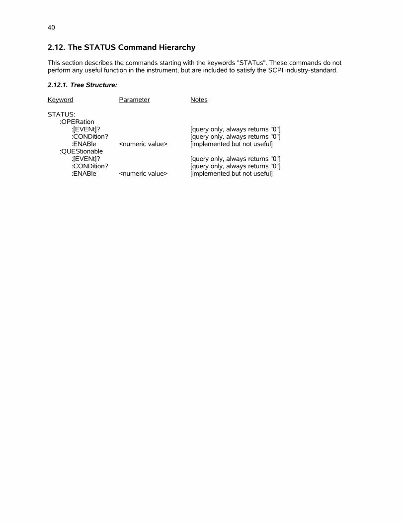
40
2.12. The STATUS Command Hierarchy
This section describes the commands starting with the keywords "STATus". These commands do not perform any useful function in the instrument, but are included to satisfy the SCPI industry-standard.
2.12.1. Tree Structure:
Keyword Parameter Notes
STATUS::OPERation
:[EVENt]? [query only, always returns "0"]:CONDition? [query only, always returns "0"]:ENABle <numeric value> [implemented but not useful]
:QUEStionable:[EVENt]? [query only, always returns "0"]:CONDition? [query only, always returns "0"]:ENABle <numeric value> [implemented but not useful]
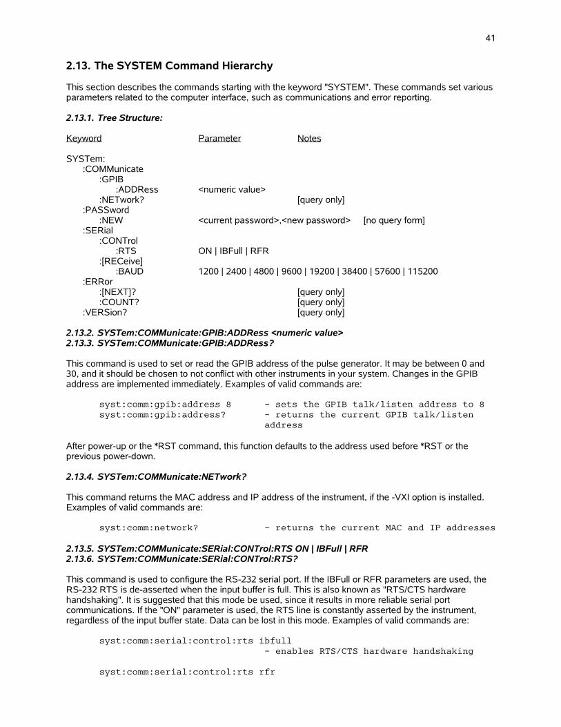
41
2.13. The SYSTEM Command Hierarchy
This section describes the commands starting with the keyword "SYSTEM". These commands set various parameters related to the computer interface, such as communications and error reporting.
2.13.1. Tree Structure:
Keyword Parameter Notes
SYSTem::COMMunicate
:GPIB:ADDRess <numeric value>
:NETwork? [query only]:PASSword
:NEW <current password>,<new password> [no query form]:SERial
:CONTrol:RTS ON | IBFull | RFR
:[RECeive]:BAUD 1200 | 2400 | 4800 | 9600 | 19200 | 38400 | 57600 | 115200
:ERRor:[NEXT]? [query only]:COUNT? [query only]
:VERSion? [query only]
2.13.2. SYSTem:COMMunicate:GPIB:ADDRess <numeric value> 2.13.3. SYSTem:COMMunicate:GPIB:ADDRess?
This command is used to set or read the GPIB address of the pulse generator. It may be between 0 and 30, and it should be chosen to not conflict with other instruments in your system. Changes in the GPIB address are implemented immediately. Examples of valid commands are:
syst:comm:gpib:address 8 - sets the GPIB talk/listen address to 8syst:comm:gpib:address? - returns the current GPIB talk/listen
address
After power-up or the *RST command, this function defaults to the address used before *RST or the previous power-down.
2.13.4. SYSTem:COMMunicate:NETwork?
This command returns the MAC address and IP address of the instrument, if the -VXI option is installed. Examples of valid commands are:
syst:comm:network? - returns the current MAC and IP addresses
2.13.5. SYSTem:COMMunicate:SERial:CONTrol:RTS ON | IBFull | RFR 2.13.6. SYSTem:COMMunicate:SERial:CONTrol:RTS?
This command is used to configure the RS-232 serial port. If the IBFull or RFR parameters are used, the RS-232 RTS is de-asserted when the input buffer is full. This is also known as "RTS/CTS hardware handshaking". It is suggested that this mode be used, since it results in more reliable serial port communications. If the "ON" parameter is used, the RTS line is constantly asserted by the instrument, regardless of the input buffer state. Data can be lost in this mode. Examples of valid commands are:
syst:comm:serial:control:rts ibfull- enables RTS/CTS hardware handshaking
syst:comm:serial:control:rts rfr
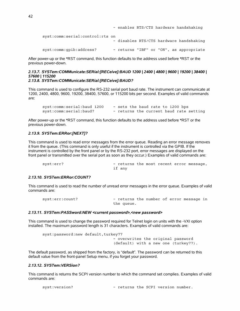
42
- enables RTS/CTS hardware handshaking
syst:comm:serial:control:rts on- disables RTS/CTS hardware handshaking
syst:comm:gpib:address? - returns "IBF" or "ON", as appropriate
After power-up or the *RST command, this function defaults to the address used before *RST or the previous power-down.
2.13.7. SYSTem:COMMunicate:SERial:[RECeive]:BAUD 1200 | 2400 | 4800 | 9600 | 19200 | 38400 | 57600 | 1152002.13.8. SYSTem:COMMunicate:SERial:[RECeive]:BAUD?
This command is used to configure the RS-232 serial port baud rate. The instrument can communicate at 1200, 2400, 4800, 9600, 19200, 38400, 57600, or 115200 bits per second. Examples of valid commands are:
syst:comm:serial:baud 1200 - sets the baud rate to 1200 bpssyst:comm:serial:baud? - returns the current baud rate setting
After power-up or the *RST command, this function defaults to the address used before *RST or the previous power-down.
2.13.9. SYSTem:ERRor:[NEXT]?
This command is used to read error messages from the error queue. Reading an error message removes it from the queue. (This command is only useful if the instrument is controlled via the GPIB. If the instrument is controlled by the front panel or by the RS-232 port, error messages are displayed on the front panel or transmitted over the serial port as soon as they occur.) Examples of valid commands are:
syst:err? - returns the most recent error message, if any
2.13.10. SYSTem:ERRor:COUNT?
This command is used to read the number of unread error messages in the error queue. Examples of validcommands are:
syst:err:count? - returns the number of error message in the queue.
2.13.11. SYSTem:PASSword:NEW <current password>,<new password>
This command is used to change the password required for Telnet login on units with the -VXI option installed. The maximum password length is 31 characters. Examples of valid commands are:
syst:password:new default,turkey77- overwrites the original password (default) with a new one (turkey77).
The default password, as shipped from the factory, is “default”. The password can be returned to this default value from the front-panel Setup menu, if you forget your password.
2.13.12. SYSTem:VERSion?
This command is returns the SCPI version number to which the command set complies. Examples of validcommands are:
syst:version? - returns the SCPI version number.

43

44
2.14. The TRIGGER Command Hierarchy
This section describes the commands starting with the keywords "TRIGger". These commands select the trigger source for the pulse generator.
2.14.1. Tree Structure:
Keyword Parameter Notes
TRIGger::SOURce INTernal | EXTernal | MANual | HOLD | IMMediate
2.14.2. TRIGger:SOURce INTernal | EXTernal | MANual | HOLD | IMMediate2.14.3. TRIGger:SOURce?
This command selects the trigger source for the instrument. Examples of valid commands are:
trig:sour INT - selects the internal clock as the trigger source
trig:sour EXT - selects the external TTL trigger input as the trigger source
trig:sour MAN - selects the "Single Pulse" pushbutton asthe trigger source. Each button press produces one pulse.
trig:sour HOLD - selects no trigger source (triggering stops)
trig:sour IMM - generates a single pulse, and then stopstriggering. This is the computer-controlled equivalent of the manual "Single Pulse" pushbutton.
After power-up or the *RST command, this function defaults to "INTERNAL".
This command is not used with function generators.

45
2.15. The IEEE 488.2 Common Command Hierarchy
This section describes the commands starting with an asterisks. These commands perform a variety of functions, and are "common commands" defined by the IEEE 488.2 standard.
Many of these commands relate to the status and error reporting system defined by the IEEE 488.2 standard. This system is outlined in the figure below. The numbers 0..7 in each register refer to the bit position in the byte-sized register.
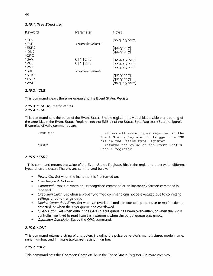
46
2.15.1. Tree Structure:
Keyword Parameter Notes
*CLS [no query form]*ESE <numeric value>*ESR? [query only]*IDN? [query only]*OPC*SAV 0 | 1 | 2 | 3 [no query form]*RCL 0 | 1 | 2 | 3 [no query form]*RST [no query form]*SRE <numeric value>*STB? [query only]*TST? [query only]*WAI [no query form]
2.15.2. *CLS
This command clears the error queue and the Event Status Register.
2.15.3. *ESE <numeric value>2.15.4. *ESE?
This command sets the value of the Event Status Enable register. Individual bits enable the reporting of the error bits in the Event Status Register into the ESB bit of the Status Byte Register. (See the figure). Examples of valid commands are:
*ESE 255 - allows all error types reported in the Event Status Register to trigger the ESB bit in the Status Byte Register
*ESE? - returns the value of the Event Status Enable register
2.15.5. *ESR?
This command returns the value of the Event Status Register. Bits in the register are set when different types of errors occur. The bits are summarized below:
Power On. Set when the instrument is first turned on. User Request. Not used. Command Error. Set when an unrecognized command or an improperly formed command is
received. Execution Error. Set when a properly-formed command can not be executed due to conflicting
settings or out-of-range data. Device-Dependent Error. Set when an overload condition due to improper use or malfunction is
detected, or when the error queue has overflowed. Query Error. Set when data in the GPIB output queue has been overwritten, or when the GPIB
controller has tried to read from the instrument when the output queue was empty. Operation Complete. Set by the OPC command.
2.15.6. *IDN?
This command returns a string of characters including the pulse generator's manufacturer, model name, serial number, and firmware (software) revision number.
2.15.7. *OPC
This command sets the Operation Complete bit in the Event Status Register. (In more complex
47
instruments, this command is used to synchronize overlapping tasks. This instrument completes commands sequentially in a non-overlapping manner, so this command is of little usefulness.)
2.15.8. *OPC?
This command always returns "1". (In more complex instruments, this command is used to synchronize overlapping tasks. This instrument completes commands sequentially in a non-overlapping manner, so this command is of little usefulness.)
2.15.9. *SAV 0 | 1 | 2 | 3
This command takes a "snapshot" of all current instrument settings (except the GPIB and RS-232 communication settings) and saves them in non-volatile (“flash”) memory. The *RCL command can be used to recall and implement these settings at a later time, even if power has been interrupted. This is designed to simplify frequently performed experiments. Four complete settings snapshots may be stored, at memory locations 0, 1, 2, or 3. Examples of valid commands are:
*SAV 2 - saves the current pulse generator setup to memory location 2
2.15.10. *RCL 0 | 1 | 2 | 3
This command restore instrument settings stored in the non-volatile (“flash”) memory by the *SAV command.Examples of valid commands are:
*SAV 3 - recalls and implements the pulse generator setup stored in memory location 3
2.15.11. *RST
This command resets the pulse generator settings to the same state as after power-up. The output and error queue are not affected, nor are the IEEE 488.2 status reporting registers.
2.15.12. *SRE2.15.13. *SRE?
These commands set or read the value of the Service Request Enable Register, which determines what events trigger a GPIB serial poll service request. If bit 5 is set high, the instrument will generate a GPIB serial poll request if one of the bits in the Event Status Register goes high while the corresponding bit in the Event Status Enable register has been enabled. If bit 4 is set high, the instrument will generate a GPIBserial poll request when a message becomes available in the output queue. The other bits are not used. If a serial poll request is generated, the RQS bit in the Status Byte Register will go high, and will stay high until a serial poll has been completed.
2.15.14. *STB?
This command returns the value of the Status Byte Register. The MAV bit of this register is high when messages are available and waiting to be read in the output queue. The ESB bit is high when one or moreof the bits in the Event Status Register in high, as well as the corresponding enabling bits in the Event Status Enable register. The MSS bit is a summary bit. The other bits are not used.
2.15.15. *TST?
This command returns a "0" when done. Any other value indicates a malfunction. This command does not perform any further functions.
2.15.16. *WAI
This command does nothing. (In more complex instruments, this command is used to synchronize

48
overlapping tasks. This instrument completes commands sequentially in a non-overlapping manner, so this command is of little usefulness.)
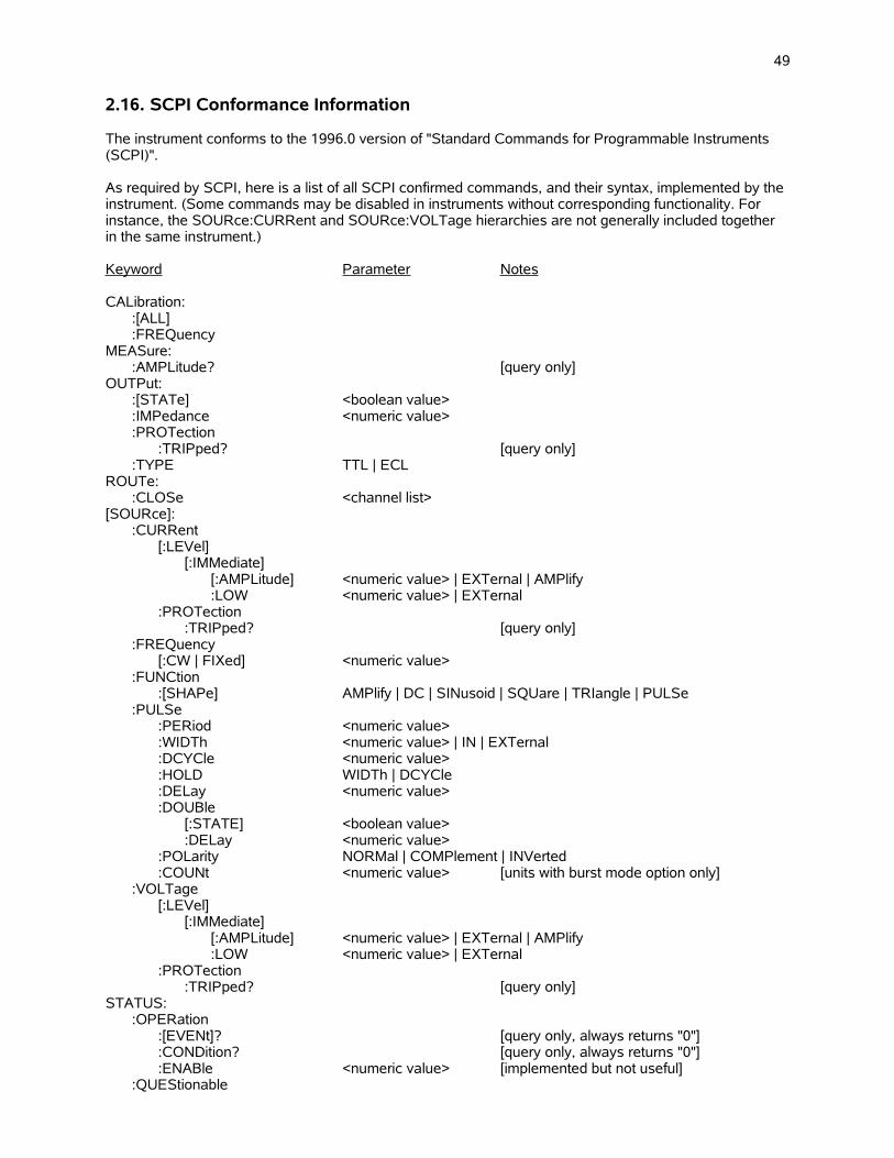
49
2.16. SCPI Conformance Information
The instrument conforms to the 1996.0 version of "Standard Commands for Programmable Instruments (SCPI)".
As required by SCPI, here is a list of all SCPI confirmed commands, and their syntax, implemented by the instrument. (Some commands may be disabled in instruments without corresponding functionality. For instance, the SOURce:CURRent and SOURce:VOLTage hierarchies are not generally included together in the same instrument.)
Keyword Parameter Notes
CALibration::[ALL]:FREQuency
MEASure::AMPLitude? [query only]
OUTPut::[STATe] <boolean value>:IMPedance <numeric value>:PROTection
:TRIPped? [query only]:TYPE TTL | ECL
ROUTe::CLOSe <channel list>
[SOURce]::CURRent
[:LEVel][:IMMediate]
[:AMPLitude] <numeric value> | EXTernal | AMPlify:LOW <numeric value> | EXTernal
:PROTection:TRIPped? [query only]
:FREQuency[:CW | FIXed] <numeric value>
:FUNCtion:[SHAPe] AMPlify | DC | SINusoid | SQUare | TRIangle | PULSe
:PULSe:PERiod <numeric value>:WIDTh <numeric value> | IN | EXTernal:DCYCle <numeric value>:HOLD WIDTh | DCYCle:DELay <numeric value>:DOUBle
[:STATE] <boolean value>:DELay <numeric value>
:POLarity NORMal | COMPlement | INVerted:COUNt <numeric value> [units with burst mode option only]
:VOLTage[:LEVel]
[:IMMediate][:AMPLitude] <numeric value> | EXTernal | AMPlify:LOW <numeric value> | EXTernal
:PROTection:TRIPped? [query only]
STATUS::OPERation
:[EVENt]? [query only, always returns "0"]:CONDition? [query only, always returns "0"]:ENABle <numeric value> [implemented but not useful]
:QUEStionable
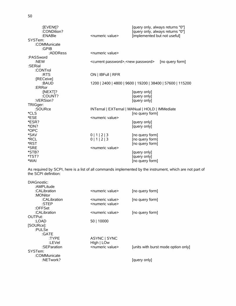
50
:[EVENt]? [query only, always returns "0"]:CONDition? [query only, always returns "0"]:ENABle <numeric value> [implemented but not useful]
SYSTem::COMMunicate
:GPIB:ADDRess <numeric value>
:PASSword:NEW <current password>,<new password> [no query form]
:SERial:CONTrol
:RTS ON | IBFull | RFR:[RECeive]
:BAUD 1200 | 2400 | 4800 | 9600 | 19200 | 38400 | 57600 | 115200:ERRor
:[NEXT]? [query only]:COUNT? [query only]
:VERSion? [query only]TRIGger:
:SOURce INTernal | EXTernal | MANual | HOLD | IMMediate*CLS [no query form]*ESE <numeric value>*ESR? [query only]*IDN? [query only]*OPC*SAV 0 | 1 | 2 | 3 [no query form]*RCL 0 | 1 | 2 | 3 [no query form]*RST [no query form]*SRE <numeric value>*STB? [query only]*TST? [query only]*WAI [no query form]
As required by SCPI, here is a list of all commands implemented by the instrument, which are not part of the SCPI definition:
DIAGnostic::AMPLitude:CALibration <numeric value> [no query form]:MONitor
:CALibration <numeric value> [no query form]:STEP <numeric value>
:OFFSet:CALibration <numeric value> [no query form]
OUTPut::LOAD 50 | 10000
[SOURce]::PULSe
:GATE:TYPE ASYNC | SYNC:LEVel HIgh | LOw
:SEParation <numeric value> [units with burst mode option only]SYSTem:
:COMMunicate:NETwork? [query only]

51
3. Error Handling and Error Messages
3.1. Error Handling
The instrument contains extensive error-checking software to protect the instrument from incorrect settings. For instance, when a command with out-of-range values is received, the command is ignored and an error is reported.
Whenever an error occurs, it is logged in an error queue, which can hold up to 32 errors. (If more errors than occur, the last error report is replaced with a "queue overflow" error.) Error reports can be viewed andremoved from the queue by using the SYSTem:ERRor:[NEXT]? query. The number of errors in the queue can be determined using the SYSTem:ERRor:COUNT? query.
When an error occurs, the Event Status Register will also be updated (see the "The IEEE 488.2 Common Command Hierarchy" section for more details.) Bits in this byte-sized register are set when different errorsin various categories occur. The four different categories are:
Command Errors. Set when an unrecognized command or an improperly formed command is received.
Execution Errors. Set when a properly-formed command can not be executed due to conflicting settings or out-of-range data.
Device-Dependent Errors. Set when an overload condition due to improper use or malfunction is detected, or when the error queue has overflowed.
Query Errors. Set when data in the GPIB output queue has been overwritten, or when the GPIB controller has tried to read from the instrument when the output queue was empty
If the corresponding bits in the Event Status Enable Register are enabled, an error will cause the ESB bit in the Status Byte Register to be set. If the corresponding bit in the Service Request Enable Register is set, this will cause the instrument to issue a service request to the GPIB controller. The GPIB controller would then initiate a serial poll. This technique can be used to monitor errors when using the GPIB.
Errors triggered by a front panel change will be reported to the front panel display, and will also be logged in the error queue and the Event Status Register, as described above.
Errors triggered by console session commands will be reported to the remote console session, and will also be logged in the error queue and the Event Status Register, as described above.
Errors triggered by internal protection sensors will be reported to the front panel, and all connected remoteconsole sessions, and will also be logged in the error queue and the Event Status Register, as described above.
3.2. Error Messages
This is a list of possible error messages, organized by category:
3.2.1. No Errors
"0, No error"
3.2.2. Command Errors
"-100, Command error; Recognized command with improper syntax.""-102, Syntax error; Unrecognized command.""-102, Syntax error; Unrecognized command. Multi-channel instruments have synchronous gating only.”“-114, Command error; channel suffix out of range.”"-131, Invalid suffix; Unrecognized units."
52
3.2.3. Execution Errors
"-200, Execution error; Specific problem unknown.""-221, Settings conflict; Duty cycle can not be set when triggering externally or manually. Set PW instead.""-221, Settings conflict; Must be externally triggered for PWin=PWout mode.""-221, Settings conflict; The double pulse separation is too large. Delay+PW can not exceed 95% of the period.""-221, Settings conflict; The amplitude+offset sum allowed is too high.”"-221, Settings conflict; The amplitude+offset sum allowed is too low.”"-221, Settings conflict; The pulse delay can not exceed 95% of the period.""-221, Settings conflict; The pulse width can not exceed the double pulse separation.""-221, Settings conflict; The pulse width can not exceed the period.""-221, Settings conflict; This is a valid command in RS232 mode only.""-222, Data out of range; Negative value not allowed.""-222, Data out of range; Parameters too high or too low.""-222, Data out of range; Internal clock frequency is too high”"-222, Data out of range; Internal clock frequency is too low”"-222, Data out of range; Pulse width is too high.""-222, Data out of range; Pulse width is too low.""-222, Data out of range; The maximum duty cycle limit has been exceeded.""-222, Data out of range; The delay is too high.""-222, Data out of range; The delay is too low.""-222, Data out of range; The amplitude is too high.""-222, Data out of range; The amplitude is too low.""-222, Data out of range; The offset is too high.""-222, Data out of range; The offset is too low.""-222, Data out of range; Amplitude must be non-zero for calibration.""-222, Data out of range; Monitor calibration changes in excess of 30% are not allowed.""-224, Illegal parameter value; Not in list of allowed values.""-240, Hardware error; this degree of calibration change can not be performed in software; needs hardware changes."
3.2.4. Device Dependent Errors
"1001, Device-specific error; Overload condition detected!"
If this error occurs, check your settings to make sure that your are not exceeding the ratings of theinstrument. If this error is displayed repeatedly at power-on, the instrument probably needs to be repaired.
"1002, Device-specific error; Internal temperature is too high!"
If this error occurs, check your settings to make sure that your are not exceeding the ratings of theinstrument. If your instrument has provision for water cooling, use it.
"1003, Device-specific error; DC power supply voltage is too high!"
If this error occurs, reduce the DC power supply voltage immediately.
"1004, Device-specific error; Remove DC power immediately! Incorrect polarity!"
If this error occurs, reduce the DC power supply voltage to zero immediately, and apply the correct polarity.
"-350, Queue overflow; The error queue has become too large. Use *cls or syst:err to clear queue."
3.2.5. Query Errors
"-400, Query error; Data has been lost in the output buffer.""-400, Query error; There is no data in the output buffer to send."