NI Multisim for Education - National Instruments Information Warranty The media on which you receive...
92
NI Multisim TM for Education NI Multisim for Education May 2008 374484C-01
Transcript of NI Multisim for Education - National Instruments Information Warranty The media on which you receive...

NI MultisimTM
for Education
NI Multisim for Education
May 2008374484C-01
Support
Worldwide Technical Support and Product Information
ni.com
National Instruments Corporate Headquarters
11500 North Mopac Expressway Austin, Texas 78759-3504 USA Tel: 512 683 0100
Worldwide Offices
Australia 1800 300 800, Austria 43 662 457990-0, Belgium 32 (0) 2 757 0020, Brazil 55 11 3262 3599, Canada 800 433 3488, China 86 21 5050 9800, Czech Republic 420 224 235 774, Denmark 45 45 76 26 00, Finland 358 (0) 9 725 72511, France 01 57 66 24 24, Germany 49 89 7413130, India 91 80 41190000, Israel 972 3 6393737, Italy 39 02 41309277, Japan 0120-527196, Korea 82 02 3451 3400, Lebanon 961 (0) 1 33 28 28, Malaysia 1800 887710, Mexico 01 800 010 0793, Netherlands 31 (0) 348 433 466, New Zealand 0800 553 322, Norway 47 (0) 66 90 76 60, Poland 48 22 3390150, Portugal 351 210 311 210, Russia 7 495 783 6851, Singapore 1800 226 5886, Slovenia 386 3 425 42 00, South Africa 27 0 11 805 8197, Spain 34 91 640 0085, Sweden 46 (0) 8 587 895 00, Switzerland 41 56 2005151, Taiwan 886 02 2377 2222, Thailand 662 278 6777, Turkey 90 212 279 3031, United Kingdom 44 (0) 1635 523545
For further support information, refer to the Technical Support and Professional Services appendix. To comment on National Instruments documentation, refer to the National Instruments Web site at ni.com/info and enter the info code feedback.
© 2006–2008 National Instruments Corporation. All rights reserved.

Important Information
WarrantyThe media on which you receive National Instruments software are warranted not to fail to execute programming instructions, due to defects in materials and workmanship, for a period of 90 days from date of shipment, as evidenced by receipts or other documentation. National Instruments will, at its option, repair or replace software media that do not execute programming instructions if National Instruments receives notice of such defects during the warranty period. National Instruments does not warrant that the operation of the software shall be uninterrupted or error free.
A Return Material Authorization (RMA) number must be obtained from the factory and clearly marked on the outside of the package before any equipment will be accepted for warranty work. National Instruments will pay the shipping costs of returning to the owner parts which are covered by warranty.
National Instruments believes that the information in this document is accurate. The document has been carefully reviewed for technical accuracy. In the event that technical or typographical errors exist, National Instruments reserves the right to make changes to subsequent editions of this document without prior notice to holders of this edition. The reader should consult National Instruments if errors are suspected. In no event shall National Instruments be liable for any damages arising out of or related to this document or the information contained in it.
EXCEPT AS SPECIFIED HEREIN, NATIONAL INSTRUMENTS MAKES NO WARRANTIES, EXPRESS OR IMPLIED, AND SPECIFICALLY DISCLAIMS ANY WARRANTY OF MERCHANTABILITY OR FITNESS FOR A PARTICULAR PURPOSE. CUSTOMER’S RIGHT TO RECOVER DAMAGES CAUSED BY FAULT OR NEGLIGENCE ON THE PART OF NATIONAL INSTRUMENTS SHALL BE LIMITED TO THE AMOUNT THERETOFORE PAID BY THE CUSTOMER. NATIONAL INSTRUMENTS WILL NOT BE LIABLE FOR DAMAGES RESULTING FROM LOSS OF DATA, PROFITS, USE OF PRODUCTS, OR INCIDENTAL OR CONSEQUENTIAL DAMAGES, EVEN IF ADVISED OF THE POSSIBILITY THEREOF. This limitation of the liability of National Instruments will apply regardless of the form of action, whether in contract or tort, including negligence. Any action against National Instruments must be brought within one year after the cause of action accrues. National Instruments shall not be liable for any delay in performance due to causes beyond its reasonable control. The warranty provided herein does not cover damages, defects, malfunctions, or service failures caused by owner’s failure to follow the National Instruments installation, operation, or maintenance instructions; owner’s modification of the product; owner’s abuse, misuse, or negligent acts; and power failure or surges, fire, flood, accident, actions of third parties, or other events outside reasonable control.
CopyrightUnder the copyright laws, this publication may not be reproduced or transmitted in any form, electronic or mechanical, including photocopying, recording, storing in an information retrieval system, or translating, in whole or in part, without the prior written consent of National Instruments Corporation.
National Instruments respects the intellectual property of others, and we ask our users to do the same. NI software is protected by copyright and other intellectual property laws. Where NI software may be used to reproduce software or other materials belonging to others, you may use NI software only to reproduce materials that you may reproduce in accordance with the terms of any applicable license or other legal restriction.
BSIM3 and BSIM4 are developed by the Device Research Group of the Department of Electrical Engineering and Computer Science, University of California, Berkeley and copyrighted by the University of California.
The ASM51 cross assembler bundled with Multisim MCU is a copyrighted product of MetaLink Corp. (www.metaice.com).
MPASM™ macro assembler and related documentation and literature is reproduced and distributed by Electronics Workbench under license from Microchip Technology Inc. All rights reserved by Microchip Technology Inc. MICROCHIP SOFTWARE OR FIRMWARE AND LITERATURE IS PROVIDED “AS IS,” WITHOUT WARRANTY OF ANY KIND, EXPRESS OR IMPLIED, INCLUDING BUT NOT LIMITED TO THE WARRANTIES OF MERCHANTABILITY, FITNESS FOR A PARTICULAR PURPOSE AND NONINFRINGEMENT. IN NO EVENT SHALL MICROCHIP BE LIABLE FOR ANY CLAIM, DAMAGES OR OTHER LIABILITY ARISING OUT OF OR IN CONNECTION WITH THE SOFTWARE OR FIRMWARE OR THE USE OF OTHER DEALINGS IN THE SOFTWARE OR FIRMWARE.
Anti-Grain Geometry - Version 2.4
Copyright (C) 2002-2004 Maxim Shemanarev (McSeem)
Permission to copy, use, modify, sell and distribute this software is granted provided this copyright notice appears in all copies. This software is provided "as is" without express or implied warranty, and with no claim as to its suitability for any purpose.
Anti-Grain Geometry - Version 2.4
Copyright (C) 2002-2005 Maxim Shemanarev (McSeem)
1. Redistribution and use in source and binary forms, with or without modification, are permitted provided that the following conditions are met:
2. Redistributions of source code must retain the above copyright notice, this list of conditions and the following disclaimer.
3. Redistributions in binary form must reproduce the above copyright notice, this list of conditions and the following disclaimer in the documentation and/or other materials provided with the distribution.
The name of the author may not be used to endorse or promote products derived from this software without specific prior written permission.
THIS SOFTWARE IS PROVIDED BY THE AUTHOR “AS IS” AND ANY EXPRESS OR IMPLIED WARRANTIES, INCLUDING, BUT NOT LIMITED TO, THE IMPLIED WARRANTIES OF MERCHANTABILITY AND FITNESS FOR A PARTICULAR PURPOSE ARE DISCLAIMED. IN NO EVENT SHALL THE AUTHOR BE LIABLE FOR ANY DIRECT, INDIRECT, INCIDENTAL, SPECIAL, EXEMPLARY, OR CONSEQUENTIAL DAMAGES (INCLUDING, BUT NOT LIMITED TO, PROCUREMENT OF SUBSTITUTE GOODS OR SERVICES; LOSS OF USE, DATA, OR PROFITS; OR BUSINESS INTERRUPTION) HOWEVER CAUSED AND ON ANY THEORY OF LIABILITY, WHETHER IN CONTRACT, STRICT LIABILITY, OR TORT (INCLUDING NEGLIGENCE OR OTHERWISE) ARISING IN ANY WAY OUT OF THE USE OF THIS SOFTWARE, EVEN IF ADVISED OF THE POSSIBILITY OF SUCH DAMAGE.
TrademarksNational Instruments, NI, ni.com, and LabVIEW are trademarks of National Instruments Corporation. Refer to the Terms of Use section on ni.com/legal for more information about National Instruments trademarks.
Ultiboard is a registered trademark and Multisim and Electronics Workbench are trademarks of Electronics Workbench.
Portions of this product obtained under license from Bartels Systems GmbH.
Other product and company names mentioned herein are trademarks or trade names of their respective companies.
Members of the National Instruments Alliance Partner Program are business entities independent from National Instruments and have no agency, partnership, or joint-venture relationship with National Instruments.
PatentsFor patents covering National Instruments products, refer to the appropriate location: Help»Patents in your software, the patents.txt file on your media, or ni.com/patents.
Some portions of this product are protected under United States Patent No. 6,560,572.
WARNING REGARDING USE OF NATIONAL INSTRUMENTS PRODUCTS(1) NATIONAL INSTRUMENTS PRODUCTS ARE NOT DESIGNED WITH COMPONENTS AND TESTING FOR A LEVEL OF RELIABILITY SUITABLE FOR USE IN OR IN CONNECTION WITH SURGICAL IMPLANTS OR AS CRITICAL COMPONENTS IN ANY LIFE SUPPORT SYSTEMS WHOSE FAILURE TO PERFORM CAN REASONABLY BE EXPECTED TO CAUSE SIGNIFICANT INJURY TO A HUMAN.
(2) IN ANY APPLICATION, INCLUDING THE ABOVE, RELIABILITY OF OPERATION OF THE SOFTWARE PRODUCTS CAN BE IMPAIRED BY ADVERSE FACTORS, INCLUDING BUT NOT LIMITED TO FLUCTUATIONS IN ELECTRICAL POWER SUPPLY, COMPUTER HARDWARE MALFUNCTIONS, COMPUTER OPERATING SYSTEM SOFTWARE FITNESS, FITNESS OF COMPILERS AND DEVELOPMENT SOFTWARE USED TO DEVELOP AN APPLICATION, INSTALLATION ERRORS, SOFTWARE AND HARDWARE COMPATIBILITY PROBLEMS, MALFUNCTIONS OR FAILURES OF ELECTRONIC MONITORING OR CONTROL DEVICES, TRANSIENT FAILURES OF ELECTRONIC SYSTEMS (HARDWARE AND/OR SOFTWARE), UNANTICIPATED USES OR MISUSES, OR ERRORS ON THE PART OF THE USER OR APPLICATIONS DESIGNER (ADVERSE FACTORS SUCH AS THESE ARE HEREAFTER COLLECTIVELY TERMED “SYSTEM FAILURES”). ANY APPLICATION WHERE A SYSTEM FAILURE WOULD CREATE A RISK OF HARM TO PROPERTY OR PERSONS (INCLUDING THE RISK OF BODILY INJURY AND DEATH) SHOULD NOT BE RELIANT SOLELY UPON ONE FORM OF ELECTRONIC SYSTEM DUE TO THE RISK OF SYSTEM FAILURE. TO AVOID DAMAGE, INJURY, OR DEATH, THE USER OR APPLICATION DESIGNER MUST TAKE REASONABLY PRUDENT STEPS TO PROTECT AGAINST SYSTEM FAILURES, INCLUDING BUT NOT LIMITED TO BACK-UP OR SHUT DOWN MECHANISMS. BECAUSE EACH END-USER SYSTEM IS CUSTOMIZED AND DIFFERS FROM NATIONAL INSTRUMENTS' TESTING PLATFORMS AND BECAUSE A USER OR APPLICATION DESIGNER MAY USE NATIONAL INSTRUMENTS PRODUCTS IN COMBINATION WITH OTHER PRODUCTS IN A MANNER NOT EVALUATED OR CONTEMPLATED BY NATIONAL INSTRUMENTS, THE USER OR APPLICATION DESIGNER IS ULTIMATELY RESPONSIBLE FOR VERIFYING AND VALIDATING THE SUITABILITY OF NATIONAL INSTRUMENTS PRODUCTS WHENEVER NATIONAL INSTRUMENTS PRODUCTS ARE INCORPORATED IN A SYSTEM OR APPLICATION, INCLUDING, WITHOUT LIMITATION, THE APPROPRIATE DESIGN, PROCESS AND SAFETY LEVEL OF SUCH SYSTEM OR APPLICATION.
Conventions
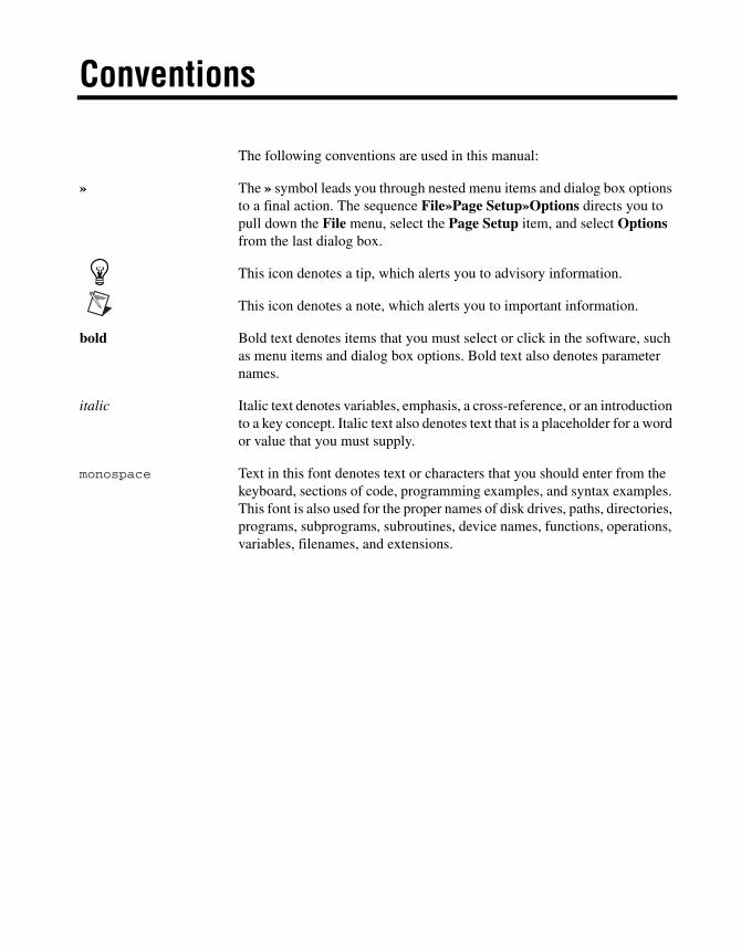
The following conventions are used in this manual:
» The » symbol leads you through nested menu items and dialog box options to a final action. The sequence File»Page Setup»Options directs you to pull down the File menu, select the Page Setup item, and select Options from the last dialog box.
This icon denotes a tip, which alerts you to advisory information.
This icon denotes a note, which alerts you to important information.
bold Bold text denotes items that you must select or click in the software, such as menu items and dialog box options. Bold text also denotes parameter names.
italic Italic text denotes variables, emphasis, a cross-reference, or an introduction to a key concept. Italic text also denotes text that is a placeholder for a word or value that you must supply.
monospace Text in this font denotes text or characters that you should enter from the keyboard, sections of code, programming examples, and syntax examples. This font is also used for the proper names of disk drives, paths, directories, programs, subprograms, subroutines, device names, functions, operations, variables, filenames, and extensions.
© National Instruments Corporation vii NI Multisim for Education
Contents
Chapter 1Educators’ Guide
Circuit Creator’s Name..................................................................................................1-1Using Restrictions..........................................................................................................1-2
Setting Global Restrictions..............................................................................1-2General Global Restrictions ..............................................................1-3
Simplified Version..............................................................1-4Global Analyses Restrictions ............................................................1-4
Setting Circuit Restrictions..............................................................................1-5Setting Passwords for Restrictions ..................................................................1-7
Link to Education Resources .........................................................................................1-8
Chapter 2Breadboarding
Breadboarding Overview...............................................................................................2-1Breadboard Settings .......................................................................................................2-13D Options .....................................................................................................................2-2Placing Components on the Breadboard........................................................................2-3
Appearance of 3D Components.......................................................................2-6Wiring Placed Components ...........................................................................................2-7
Placing a Jumper..............................................................................................2-7Changing Jumper Wire Color..........................................................................2-9
Viewing Component Information ..................................................................................2-9Two-terminal Components..............................................................................2-10
Manipulating the Breadboard View...............................................................................2-11Breadboard Netlist dialog box .......................................................................................2-12DRC and Connectivity Check........................................................................................2-13
Chapter 3Virtual NI ELVIS
Overview........................................................................................................................3-1The Virtual NI ELVIS I Schematic ...............................................................................3-1
NI ELVIS I Instruments ..................................................................................3-4Oscilloscope ......................................................................................3-5IV Analyzer and Multimeter .............................................................3-6Function Generator ...........................................................................3-8Variable Power Supply .....................................................................3-9
Contents
NI Multisim for Education viii ni.com
NI ELVIS II Instruments ............................................................................................... 3-9Oscilloscope .................................................................................................... 3-10Dynamic Signal Analyzer ............................................................................... 3-11Digital Multimeter........................................................................................... 3-13Arbitrary Waveform Generator....................................................................... 3-15Function Generator ......................................................................................... 3-17Variable Power Supply ................................................................................... 3-19Digital Reader ................................................................................................. 3-21Digital Writer .................................................................................................. 3-23NI ELVISmx Instruments Toolbar ................................................................. 3-24
The Virtual NI ELVIS II Schematic.............................................................................. 3-25Enabling NI ELVIS II Schematic Instruments for Simulation ....................... 3-28
NI ELVIS Prototyping Boards ...................................................................................... 3-30Wiring Placed Components in 3D Mode ........................................................ 3-35
Chapter 4Ladder Diagrams
Overview ....................................................................................................................... 4-1Creating a Ladder Diagram ........................................................................................... 4-1AND Rungs and OR Rungs........................................................................................... 4-6Sample Circuits ............................................................................................................. 4-8
Holding Tank .................................................................................................. 4-8Conveyor Belt ................................................................................................. 4-15Traffic Light .................................................................................................... 4-20
Appendix ATechnical Support and Professional Services
Index
© National Instruments Corporation 1-1 NI Multisim for Education
1Educators’ Guide
Multisim is the schematic capture and simulation application of National Instruments Circuit Design Suite, a suite of EDA (Electronics Design Automation) tools that assists you in carrying out the major steps in the circuit design flow. Multisim is designed for schematic entry, simulation, and feeding to downstage steps, such as PCB layout.
In addition to the professional features that are detailed in the NI Multisim User Manual, there are a number of education-specific features that are outlined in this manual.
This chapter describes the tools that Multisim offers to let you exercise greater control over the program’s interface and functionality when sharing circuits with students, as well as to set certain aspects of a circuit’s behavior for instructional purposes.
Some of the described features may not be available in the Student edition of Multisim. Refer to the release notes for a description of the features available in your edition.
Circuit Creator’s NameMultisim provides a feature by which the name of the creator of each circuit is stored with that circuit. Educators can take advantage of this feature to identify the student who, for example, created the circuit being submitted as the answer to an assignment (provided that the student uses his/her own copy of the program to create the circuit). The name appears in the Circuit Restrictions dialog box, which you can view as long as no passwords have been set. Refer to the Setting Circuit Restrictions section for more information.

Chapter 1 Educators’ Guide
NI Multisim for Education 1-2 ni.com
Using RestrictionsRestrictions are useful in a number of ways:
• when you are designing circuits for demonstration purposes and want to limit the functionality available to students
• when you are sharing circuits with students and want:
– to prevent them from being able to edit the circuit in any way
– to limit the types of modifications they can make to a circuit
– to limit the types of analyses they can perform on it
– to limit the information they can see about certain parts of the circuit (for example, the value of a resistor you want them to calculate).
You can set global-level restrictions, which become default Multisim settings, or circuit-level restrictions, which affect only specific circuits. To ensure that only you can set or modify restrictions, you use passwords which can protect both global and circuit restrictions. It is important that you set passwords immediately when using restrictions that you want to keep secure against any modification by students. The password for global restrictions is encrypted and stored in the Multisim program file. The password for circuit restrictions (for restricting only a particular circuit) is encrypted and stored in the circuit file.
Setting Global Restrictions Use global restrictions to set the basic level of functionality of Multisim available to students in all circuits with which they will work. You can select a default path where circuits are to be saved, hide databases and the In Use List, and determine whether students may edit components or place instruments.
You can also hide complicated instruments and analysis options from the menus by using the simplified version. Refer to the Simplified Version section for more information.
Note Global restrictions are overridden by circuit restrictions if the circuit restrictions are saved with the circuit. Refer to the Setting Circuit Restrictions section for more information.
Chapter 1 Educators’ Guide
© National Instruments Corporation 1-3 NI Multisim for Education
General Global Restrictions Complete the following steps to set general global restrictions:
1. Choose Options»Global Restrictions. The Password dialog box appears.
Note The Password dialog also appears if you select Options»Circuit Restrictions, if you have previously set a password by clicking Password from the Circuit restrictions dialog box. Refer to the Setting Circuit Restrictions section for information about the Circuit restrictions dialog box.
2. Enter the default password “Rodney” (this is case sensitive) and click OK. The Global restrictions dialog box appears.
Note You can, and should, change the default password. Refer to the Setting Passwords for Restrictions section for more information.
3. Click the General tab.
4. Set the default path and location where students find and save files in the Circuit Path field.
5. Set the following as desired in the Toolbars box:
• Disable Instruments toolbar—Makes instruments unavailable to be placed in the circuit.
• Disable In-Use List toolbar—Hides the In Use List.
6. Set the following as desired in the Databases box:
• Disable database editing—Ensures that students cannot edit components in the database.
• Disable Master DB component access—Hides the Multisim Master database and parts groups and families from the interface.
• Disable Corporate DB component access—Hides the corporate database and parts groups and families from the interface.
• Disable User DB component access—Hides the “user” database and parts groups and families from the interface.
7. Click OK. Your options are immediately set for all circuits, unless you have set circuit restrictions. Refer to the Setting Circuit Restrictions section for more information.
Chapter 1 Educators’ Guide
NI Multisim for Education 1-4 ni.com
Simplified Version The simplified version restricts students to only certain instruments and analyses. The simplified version can also be locked, preventing students from turning it off with Options»Simplified Version and having access to all analyses and instruments.
Complete the following steps to set up the simplified version:
1. Display the General tab of the Global Restrictions dialog box.
2. Set your options by enabling one of the following options:
• Lock simplified—Disables the Options»Simplified Version menu option.
• Simplified version—Changes the interface display by hiding the more complex functions and restricting the available instruments and analyses. If the simplified version is restricted, it will be greyed out in the Options menu.
• Full version—Displays the full default interface without restrictions.
3. Click OK.
Your options are immediately set for all circuits, unless you have set circuit restrictions. Refer to the Setting Circuit Restrictions section for more information.
Global Analyses Restrictions Complete the following steps to set global analyses restrictions:
1. From the Global Restrictions dialog box, click the Analysis tab.
2. Enable the desired analyses by selecting their checkboxes and click OK. Only the analyses you check will be enabled in the Simulate»Analyses menu or when the student clicks the Grapher/Analyses List button in the Main toolbar.
Note Refer to the Analysis chapter in the Multisim User Manual for more information on analyses.
These options are immediately set for all circuits, unless you have set circuit restrictions. Refer to the Setting Circuit Restrictions section for more information.

Chapter 1 Educators’ Guide
© National Instruments Corporation 1-5 NI Multisim for Education
Setting Circuit Restrictions Use circuit restrictions to set restrictions on individual circuits. Circuit restrictions override global restrictions. They are saved with your circuit and invoked each time the circuit is loaded. In addition to hiding databases and setting available analyses, you can set a schematic to be read-only (not editable by students), you can hide components’ values, faults and uses in analyses, and you can lock subcircuits to make them unavailable for opening by students.
Note Remember that circuit restrictions only apply to the current circuit; when you create a new circuit, only the global restrictions will apply. Refer to the Setting Global Restrictions section for more information. If you want circuit restrictions to apply to a new circuit, you will need to reset those restrictions each time you create a new circuit.
Complete the following steps to set general circuit restrictions:
1. Choose Options»Circuit Restrictions. If you have created a password, you will be prompted for it. Refer to the Setting Passwords for Restrictions section for more information. Enter your password in the Password dialog box, and click OK. The Circuit Restrictions dialog box appears.
2. Click the General tab and set the desired options by enabling the appropriate checkboxes. Select from the following options:
• Schematic read-only—Prevents students from saving the circuit, and hides parts bins. Students will only be able to draw wires between instruments and an open pin on an existing connector. Also, they can only remove wires that are between an instrument and a connector.
• Circuit description read-only—Prevents students from changing the contents of the Circuit Description box.
• Hide component values—Marks the Values tab of components’ properties dialog boxes with an “X” and hides values. You may wish to provide false values using labels.
• Hide component faults—Marks the Faults tab of components’ properties dialog boxes with an “X”, and hides faults.
• Lock subcircuits—Prevents students from opening subcircuits and seeing their contents. Students must measure the input and output of a hidden subcircuit to determine its contents.
• Disable Instruments toolbar—Makes instruments unavailable to be placed on the circuit.
Chapter 1 Educators’ Guide
NI Multisim for Education 1-6 ni.com
• Disable In-Use List toolbar—Disables the In-Use List for the current circuit.
• Disable Multisim Master DB component access—Hides the Multisim Master database and parts groups and families from the current circuit.
• Disable User DB component access—Hides the user database and parts groups and families from the current circuit.
• Disable Corporate DB component access—Hides the corporate database and parts groups and families from the interface.
Note The Circuit Creator Name is taken from the operating system.
3. Click OK. The options you select are immediately invoked in the circuit.
4. To have the restrictions apply each time the circuit is opened, choose File»Save to save the restrictions in the circuit file.
Complete the following steps to set circuit analyses restrictions:
1. From the Circuit Restrictions dialog box, click the Analysis tab.
2. Enable the desired analyses by selecting their checkboxes and click OK. Only the analyses you check will be enabled in the Simulate»Analyses menu or when the student clicks the Grapher/Analyses List button in the Main toolbar.
Note Refer to the Analysis chapter in the Multisim User Manual for more information on analyses.
3. To have these analyses apply each time the circuit is opened, choose File»Save to save the restrictions.
Complete the following steps to set circuit breadboard restrictions:
1. From the Circuit Restrictions dialog box, click the Breadboard tab.
2. Set the following as desired:
• Highlight Target Holes—Disable if you do not wish to see where the targets for jumper wires are when placing them on the breadboard.
• Completion Feedback—Disable if you do not wish components and wires on the schematic to change color as they are placed and wired on the breadboard.
3. Click OK.
Note For details on breadboarding, refer to Chapter 2, Breadboarding.
Chapter 1 Educators’ Guide
© National Instruments Corporation 1-7 NI Multisim for Education
Setting Passwords for Restrictions When using restrictions, you should create a password immediately to ensure that your settings are secure.
Complete the following steps to create/change a password:
1. For global restrictions, choose Options»Global Restrictions.
Or
For circuit restrictions, choose Options»Circuit Restrictions.
2. Enter a password if prompted to do so.
Note The default password for global restrictions is “Rodney” (this is case sensitive). Circuit restrictions do not have a default password.
3. From the restrictions dialog box that appears, click Password. The Change password dialog box appears.
4. If you are choosing a password for the first time, leave the Old password field blank.
5. If you are changing a password, enter the old password in the Old password field.
6. Enter your (new) password in the New password field.
7. Confirm your new password by entering it again in the Confirm password field.
8. Click OK to return to the dialog box, or Cancel to begin again.
Note If you want to change global or circuit restrictions, you will need to enter the respective password. Be sure to keep your passwords for both the Global restrictions and Circuit restrictions dialogs written down and in a safe place, as you will not be able to retrieve them from the program or circuit files, where they are stored in encrypted form.
Note A circuit password is not automatically transferred to a new circuit when you go to set circuit restrictions for it, so you will need to recreate the password every time you create circuit restrictions that you want to keep secure.

Chapter 1 Educators’ Guide
NI Multisim for Education 1-8 ni.com
Link to Education Resources
Note This function is hidden when the simplified version option is selected. Refer to the Simplified Version section for more information.
To go to the National Instruments Academic website, click the Educational Website button or select Tools»Education Webpage.
© National Instruments Corporation 2-1 NI Multisim for Education
2Breadboarding
This chapter describes Multisim’s breadboarding feature.
Some of the features described in this chapter may not be available in your edition of Multisim. Refer to the release notes for a description of the features available in your edition.
Breadboarding Overview The Breadboarding feature provides a technical aid for educators who wish to illustrate breadboarding as a means of prototyping circuit designs. It also gives students exposure to the breadboarding process, and shows in 3D what the resulting breadboard will look like when completed.
Breadboard Settings The default breadboard is shown in the screen capture below. If you wish to change the default settings, use the following procedure.
Complete the following steps to change the breadboard’s settings:
1. Select Tools»Show Breadboard from the main Multisim menu. The Breadboard View displays. The default breadboard appears as shown below.

Chapter 2 Breadboarding
NI Multisim for Education 2-2 ni.com
As shown in the figure above, the default breadboard contains: one slat with two rows (1); one left strip (2); one bottom strip (3); one right strip (4); one top strip (5).
2. Select Options»Breadboard Settings to display the Breadboard Settings dialog box.
3. Enter the desired parameters for the breadboard and click OK. The view of the breadboard changes to reflect your changes.
3D Options The 3D viewing options for the Breadboard View are set in the 3D Options tab of the Preferences dialog box.
Complete the following steps to change the 3D options:
1. Select Options»Global Preferences and click on the 3D Options tab.
2. Optionally, click on Background color to display a standard Color dialog box where you can adjust the background color as desired.
3. In the Info Box area:
• Info Box—Disable this checkbox if you do not wish to see the box at the top of the Breadboard View that shows parts information.
• Left—Places parts information box at top-left.
• Center—Places parts information box at top-center.
• Right—Places parts information box at top-right.
1 One Slat with Rows2 Left Strip
3 Bottom Strip4 Right Strip
5 Top Strip
Chapter 2 Breadboarding
© National Instruments Corporation 2-3 NI Multisim for Education
4. Disable the Show Target Holes checkbox if you do not wish to see where the targets for jumper wires are when placing them. Refer to the Placing a Jumper section for more information.
5. Disable the Show Completion Feedback checkbox if you do not wish components and wires on the schematic to change color as they are placed and wired on the breadboard.
6. In the 3D Performance box:
• Move the slider as desired to improve graphic performance. More Details will result in a slower screen refresh rate.
• Enable the User Defined checkbox and disable the 3D features that you do not wish to see.
Tip Disabling Show Breadboard Numbers will result in a much quicker refresh rate.
Placing Components on the Breadboard Complete the following steps to place components on a breadboard:
1. Create a schematic diagram of the desired circuit in the usual manner. (For details, on schematic capture, refer to the Multisim User Manual.)
2. Select Tools»Show Breadboard from the main Multisim menu. The Breadboard View displays similar to the following example.
Chapter 2 Breadboarding
NI Multisim for Education 2-4 ni.com
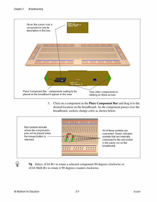
3. Click on a component in the Place Component Bar and drag it to the desired location on the breadboard. As the component passes over the breadboard, sockets change color as shown below.
Tip Select <Ctrl-R> to rotate a selected component 90 degrees clockwise or <Ctrl-Shift-R> to rotate it 90 degrees counter-clockwise.

Chapter 2 Breadboarding
© National Instruments Corporation 2-5 NI Multisim for Education
4. Release the mouse button to place the component. Notice that the colored (red and green) sockets on the breadboard no longer appear.
5. Return to the schematic view and note that the color of the placed component has changed as shown in the example below (R1).

Chapter 2 Breadboarding
NI Multisim for Education 2-6 ni.com
6. Continue placing the circuit’s components on the breadboard. When all the components have been placed, the Place Component Bar collapses as shown below.
Tip Where pins of components are connected on the schematic, you can place them in connected sockets on the breadboard as shown below. This technique can reduce the number of jumper wires required. Refer to the Placing a Jumper section for more information about jumpers.
Appearance of 3D Components The appearance of the 3D component is dependant on the footprint that is selected from the Select a Component browser during schematic capture in the Footprint manuf./Type list.
Chapter 2 Breadboarding
© National Instruments Corporation 2-7 NI Multisim for Education
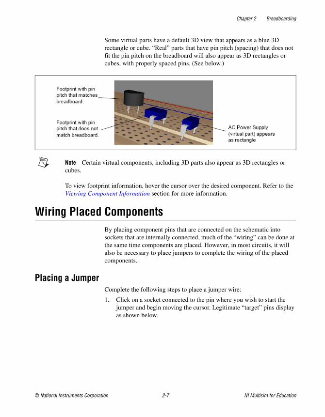
Some virtual parts have a default 3D view that appears as a blue 3D rectangle or cube. “Real” parts that have pin pitch (spacing) that does not fit the pin pitch on the breadboard will also appear as 3D rectangles or cubes, with properly spaced pins. (See below.)
Note Certain virtual components, including 3D parts also appear as 3D rectangles or cubes.
To view footprint information, hover the cursor over the desired component. Refer to the Viewing Component Information section for more information.
Wiring Placed Components By placing component pins that are connected on the schematic into sockets that are internally connected, much of the “wiring” can be done at the same time components are placed. However, in most circuits, it will also be necessary to place jumpers to complete the wiring of the placed components.
Placing a JumperComplete the following steps to place a jumper wire:
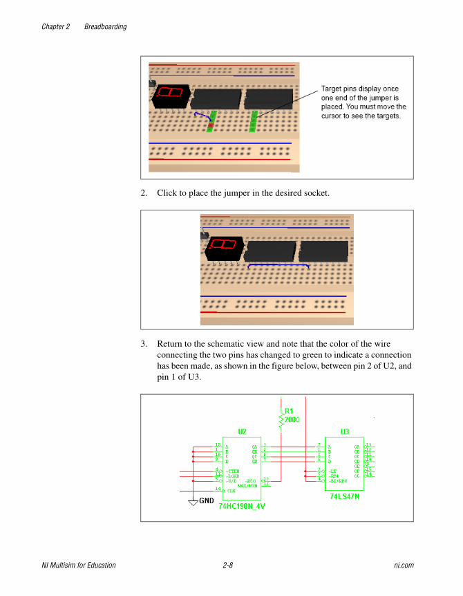
1. Click on a socket connected to the pin where you wish to start the jumper and begin moving the cursor. Legitimate “target” pins display as shown below.
Chapter 2 Breadboarding
NI Multisim for Education 2-8 ni.com
2. Click to place the jumper in the desired socket.
3. Return to the schematic view and note that the color of the wire connecting the two pins has changed to green to indicate a connection has been made, as shown in the figure below, between pin 2 of U2, and pin 1 of U3.
Chapter 2 Breadboarding
© National Instruments Corporation 2-9 NI Multisim for Education
Note If a net contains more than two connections, all must be connected before any of the wires in the net change color.
4. Continue placing jumpers until all schematic connections have been made.
Tip Run a Design Rules and Connectivity Check to see if there are any errors in your breadboard. Refer to the DRC and Connectivity Check section for more information.
Changing Jumper Wire ColorComplete the following steps to change jumper wire color:
1. Select Edit»Breadboard Wire Color.
2. Select the desired color from the dialog box that appears.
Note The color of previously placed wires is not affected. The new color will be applied to any subsequently placed wires.
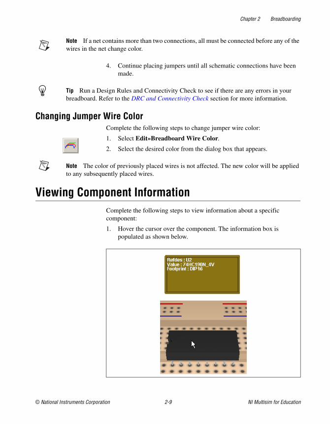
Viewing Component InformationComplete the following steps to view information about a specific component:
1. Hover the cursor over the component. The information box is populated as shown below.

Chapter 2 Breadboarding
NI Multisim for Education 2-10 ni.com
Complete the following steps to see pin information:
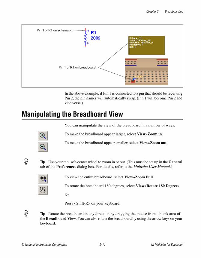
1. Hover the cursor over the “metal” part of the desired pin. The information box now includes the pin name and the schematic net to which the pin should be connected.
Two-terminal Components Two-terminal non-directional components like resistors have symbol pin names (1 and 2) that will automatically swap if they are connected the “wrong way” according to the pin name that is on the schematic.
Complete the following steps to view the pin names for all devices on the schematic:
1. Select Options»Sheet Properties and click the Circuit tab of the Sheet Properties dialog box.
2. Click the Symbol Pin Names checkbox until the checkmark is a solid black color and click OK to close the dialog.
Chapter 2 Breadboarding
© National Instruments Corporation 2-11 NI Multisim for Education
In the above example, if Pin 1 is connected to a pin that should be receiving Pin 2, the pin names will automatically swap. (Pin 1 will become Pin 2 and vice versa.)
Manipulating the Breadboard View You can manipulate the view of the breadboard in a number of ways.
To make the breadboard appear larger, select View»Zoom in.
To make the breadboard appear smaller, select View»Zoom out.
Tip Use your mouse’s center wheel to zoom in or out. (This must be set up in the General tab of the Preferences dialog box. For details, refer to the Multisim User Manual.)
To view the entire breadboard, select View»Zoom Full.
To rotate the breadboard 180 degrees, select View»Rotate 180 Degrees.
Or
Press <Shift-R> on your keyboard.
Tip Rotate the breadboard in any direction by dragging the mouse from a blank area of the Breadboard View. You can also rotate the breadboard by using the arrow keys on your keyboard.
Chapter 2 Breadboarding
NI Multisim for Education 2-12 ni.com
To pan the breadboard, hold down the Shift key on your keyboard and use any of the arrow keys.
Or
Press <Ctrl-Shift> and drag the mouse.
Or
Hold down your mouse-wheel and drag the mouse.
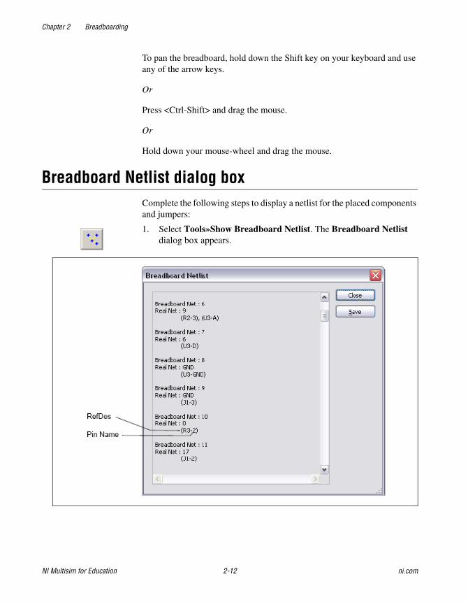
Breadboard Netlist dialog box Complete the following steps to display a netlist for the placed components and jumpers:
1. Select Tools»Show Breadboard Netlist. The Breadboard Netlist dialog box appears.
Chapter 2 Breadboarding
© National Instruments Corporation 2-13 NI Multisim for Education
2. Optionally, click Save to save the breadboard netlist as a .txt or .csv file.
Note These nets are breadboard connections, and are not necessarily numbered in correspondence to the schematic nets.
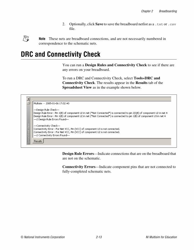
DRC and Connectivity CheckYou can run a Design Rules and Connectivity Check to see if there are any errors on your breadboard.
To run a DRC and Connectivity Check, select Tools»DRC and Connectivity Check. The results appear in the Results tab of the Spreadsheet View as in the example shown below.
Design Rule Errors—Indicate connections that are on the breadboard that are not on the schematic.
Connectivity Errors—Indicate component pins that are not connected to fully-completed schematic nets.
© National Instruments Corporation 3-1 NI Multisim for Education
3Virtual NI ELVIS
This chapter describes Multisim’s virtual NI ELVIS feature.
Some of the features described in this chapter may not be available in your edition of Multisim. Refer to the release notes for a description of the features available in your edition.
Overview Virtual NI ELVIS emulates much of the behavior of its real-world counter-part, the NI Educational Laboratory Virtual Instrumentation Suite (NI ELVIS). Planning, prototyping and testing of instructors’ projects can be carried out on students’ PCs before moving on to the real NI ELVIS I or NI ELVIS II workstation in the lab.
Multisim emulates both the original NI ELVIS I and NI ELVIS II. For details, refer to The Virtual NI ELVIS I Schematic andThe Virtual NI ELVIS II Schematic sections.
The Virtual NI ELVIS I Schematic A virtual NI ELVIS I schematic contains a number of items that correspond to elements of the real-world NI ELVIS workstation. The connection and control of these elements is described in this section.
Note This section describes the behavior of Multisim’s original NI ELVIS I schematic. Refer to The Virtual NI ELVIS II Schematic section for information on Multisim’s NI ELVIS II functionality.
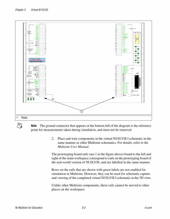
Complete the following steps to create a new virtual NI ELVIS I schematic:
1. Select File»New»NI ELVIS I Schematic. The schematic appears as shown below:
Chapter 3 Virtual NI ELVIS
NI Multisim for Education 3-2 ni.com
Note The ground connector that appears at the bottom left of the diagram is the reference point for measurements taken during simulation, and must not be removed.
2. Place and wire components in the virtual NI ELVIS I schematic in the same manner as other Multisim schematics. For details, refer to the Multisim User Manual.
The prototyping board rails (see 1 in the figure above) found to the left and right of the main workspace correspond to rails on the prototyping board of the real-world version of NI ELVIS, and are labelled in the same manner.
Rows on the rails that are shown with green labels are not enabled for simulation in Multisim. However, they can be used for schematic capture and viewing of the completed virtual NI ELVIS I schematic in the 3D view.
Unlike other Multisim components, these rails cannot be moved to other places on the workspace.
1 Rails

Chapter 3 Virtual NI ELVIS
© National Instruments Corporation 3-3 NI Multisim for Education
LEDsConnections to the eight LEDs on the right side of the NI ELVIS I schematic are found in the lower-right prototyping rail, as shown in the figure below (2). During simulation, any of these LEDs (1) that are correctly driven will light.
1 LEDs 2 LED Connections
Chapter 3 Virtual NI ELVIS
NI Multisim for Education 3-4 ni.com
Complete the following to connect to an LED:
1. Place a wire from one of the LED rows (LED 0 through LED 7) to the desired point in your schematic.
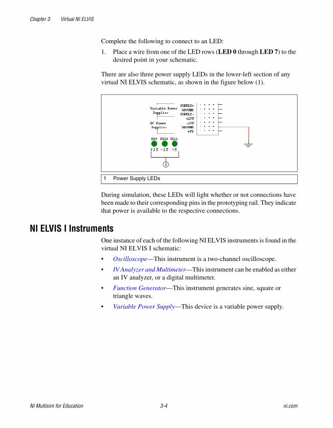
There are also three power supply LEDs in the lower-left section of any virtual NI ELVIS schematic, as shown in the figure below (1).
During simulation, these LEDs will light whether or not connections have been made to their corresponding pins in the prototyping rail. They indicate that power is available to the respective connections.
NI ELVIS I Instruments One instance of each of the following NI ELVIS instruments is found in the virtual NI ELVIS I schematic:
• Oscilloscope—This instrument is a two-channel oscilloscope.
• IV Analyzer and Multimeter—This instrument can be enabled as either an IV analyzer, or a digital multimeter.
• Function Generator—This instrument generates sine, square or triangle waves.
• Variable Power Supply—This device is a variable power supply.
1 Power Supply LEDs
Chapter 3 Virtual NI ELVIS
© National Instruments Corporation 3-5 NI Multisim for Education
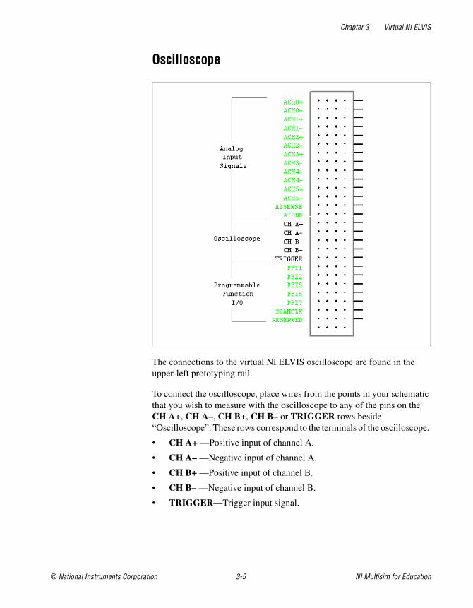
Oscilloscope
The connections to the virtual NI ELVIS oscilloscope are found in the upper-left prototyping rail.
To connect the oscilloscope, place wires from the points in your schematic that you wish to measure with the oscilloscope to any of the pins on the CH A+, CH A–, CH B+, CH B– or TRIGGER rows beside “Oscilloscope”. These rows correspond to the terminals of the oscilloscope.
• CH A+ —Positive input of channel A.
• CH A– —Negative input of channel A.
• CH B+ —Positive input of channel B.
• CH B– —Negative input of channel B.
• TRIGGER—Trigger input signal.
Chapter 3 Virtual NI ELVIS
NI Multisim for Education 3-6 ni.com
Complete the following steps to access the oscilloscope’s controls:
1. Double-click on the the word “Oscilloscope” in the upper-left prototyping rail. The instrument face for the Multisim virtual oscilloscope displays.
2. Refer to the Multisim User Manual for details on the use of this instrument.
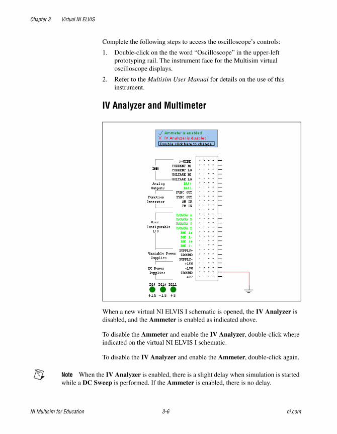
IV Analyzer and Multimeter
When a new virtual NI ELVIS I schematic is opened, the IV Analyzer is disabled, and the Ammeter is enabled as indicated above.
To disable the Ammeter and enable the IV Analyzer, double-click where indicated on the virtual NI ELVIS I schematic.
To disable the IV Analyzer and enable the Ammeter, double-click again.
Note When the IV Analyzer is enabled, there is a slight delay when simulation is started while a DC Sweep is performed. If the Ammeter is enabled, there is no delay.

Chapter 3 Virtual NI ELVIS
© National Instruments Corporation 3-7 NI Multisim for Education
Complete the following to connect the IV Analyzer:
1. Place wires from the component you wish to measure to the pins on the 3-WIRE, CURRENT HI and CURRENT LO rows. These rows correspond to the inputs of the IV Analyzer. Refer to the figure below for connections for a diode (1); PNP BJT (2); NPN BJT (3); NMOS FET (4); PMOS FET (5).
Complete the following to connect the Ammeter:
1. Place wires from the points in the circuit you wish to measure to the pins on the CURRENT HI and CURRENT LO rows.
CURRENT HI corresponds to the + terminal of the ammeter and CURRENT LO corresponds to the – terminal.
Complete the following steps to access the controls for the enabled instrument:
1. Double-click just above the letters “DMM”. If you have enabled the IV Analyzer as described earlier, that instrument’s face appears. If you have enabled the Ammeter, an instrument containing the Ammeter function of a multimeter appears.
2. Refer to the Multisim User Manual for details on the use of these instruments.
1 Diode2 PNP BJT
3 NPN BJT4 NMOS
5 PMOS
Chapter 3 Virtual NI ELVIS
NI Multisim for Education 3-8 ni.com
Complete the following to connect the Volt/Ohmmeter:
1. Place wires from the points in the circuit you wish to measure to the pins on the VOLTAGE HI and VOLTAGE LO rows.
VOLTAGE HI corresponds to the + terminal of the meter and VOLTAGE LO corresponds to the – terminal.
Complete the following steps to access the controls for the Voltmeter and Ohmmeter:
1. Double-click just below the letters “DMM”. An instrument containing the Voltmeter and Ohmmeter functions of a multimeter appears.
2. Refer to the Multisim User Manual for details on the use of this instrument.
Function Generator Complete the following to connect the Function Generator:
1. Place wires from the pins on the FUNC OUT, SYNC OUT, AM IN and FM IN rows to the desired points in your schematic.
• FUNC OUT—Output signal.
• SYNC OUT—Outputs a TTL-compatible clock signal of the same frequency as the output waveform.
• AM IN—A signal input here controls the amplitude of the signal at FUNC OUT.
• FM IN—A signal input here controls the frequency of the signal at FUNC OUT and SYNC OUT.
Complete the following steps to access the controls for the Function Generator:
1. Double-click on Function Generator. The properties dialog for the NI ELVIS Function Generator appears.
2. Click on the Value tab and enter the desired output parameters.
3. Click OK to close the Function Generator’s properties dialog box.
Note Refer to the Component Reference help file for information about the user-settable parameters.
Note This instrument can be used for transient analysis only. This will not function for frequency-domain analyses. To run a frequency-domain analysis, use an AC source from the Master Multisim database. For more information on analyses, refer to the Multisim User Manual.
Chapter 3 Virtual NI ELVIS
© National Instruments Corporation 3-9 NI Multisim for Education
Variable Power Supply The lower-left prototyping rail contains the following fixed DC power supplies:
• +15 V
• –15 V
• +5 V (also found in the lower-right prototyping rail.)
Variable Power Supplies are also available:
• SUPPLY + (+12 V max.)
• SUPPLY – (–12 V max.)
To connect to any of the power supplies, place wires from the pin on the corresponding row to the desired point in the circuit.
Complete the following steps to access the controls for the variable power supply:
1. Double-click on Variable Power Supplies. The properties dialog box for the NI ELVIS power supply appears.
2. Click on the Value tab and enter the desired parameters.
3. Click OK to close the properties dialog box.
Note Refer to the Component Reference help file for information about the user-settable parameters.
NI ELVIS II Instruments The following NI ELVIS II instruments are available in Multisim:
• Oscilloscope—This instrument is a two-channel oscilloscope.
• Dynamic Signal Analyzer—This instrument computes and displays the RMS averaged power spectrum of a single channel.
• Digital Multimeter—This instrument is a digital multimeter.
• Arbitrary Waveform Generator—This instrument generates user-specified waveforms.
• Function Generator—This instrument generates sine, square or triangle waves.
• Variable Power Supply—This device is a variable DC power supply.
• Digital Reader—This instrument reads digital data.

Chapter 3 Virtual NI ELVIS
NI Multisim for Education 3-10 ni.com
• Digital Writer—This instrument updates the digital output on the NI ELVIS II Prototyping Board with user-specific digital patterns.
There are three ways to access NI ELVIS II instruments:
• Use the pre-placed icons found on the NI ELVIS II schematic rails and platform control panel sections.
• Place them from the menu onto any Multisim workspace using Simulate»Instruments»NI ELVISmx Instruments»<instrument>.
• Place them from the NI ELVISmx Instruments toolbar onto any Multisim workspace. Refer to the NI ELVISmx Instruments Toolbar section for more information.
An NI ELVIS II instrument soft front panel (SFP) is where you find that instrument’s controls. To access any NI ELVIS II instrument’s SFP, double-click on its icon.
Oscilloscope This instrument is a two-channel oscilloscope.
In NI ELVIS II schematics, this instrument’s pre-placed icon is located in the NI ELVIS II Platform Control Panel Scope Section of the NI ELVIS II schematic, as shown in the figure below (1).
Complete the following step to connect the instrument:
1. Place wires from the desired points in your schematic to the pins on the NI ELVIS II Front Control Panel Scope Section described below:
• TRIG—Trigger input.
• CH 0 + —Positive input of channel 0.
• CH 0 – —Negative input of channel 0.
• CH 1+ —Positive input of channel 1.
• CH 1– —Negative input of channel 1.
1 Oscilloscope Icon

Chapter 3 Virtual NI ELVIS
© National Instruments Corporation 3-11 NI Multisim for Education
Complete the following steps to access the SFP:
1. Double-click the instrument’s icon, shown in the figure above (1). The SFP appears.
2. Change the settings in the SFP as desired.
Complete the following steps to place this instrument directly onto any Multisim workspace:
1. Select Simulate»Instruments»NI ELVISmx Instruments»NI ELVISmx Oscilloscope.
2. Click to place the instrument in the desired location on the workspace. Its icon appears as shown below:
3. Wire in the same manner as any other Multisim instrument.
Note You can also use the NI ELVISmx Instruments toolbar to place this instrument. Refer to the NI ELVISmx Instruments Toolbar section for more information.
For information about using this instrument, click the Help button on its SFP to display the NI ELVIS help file.
Dynamic Signal Analyzer The NI ELVIS Dynamic Signal Analyzer computes and displays the RMS averaged power spectrum of a single channel. A variety of windowing and averaging modes can be applied to the signal. It also detects the peak frequency component and estimates the actual frequency and power.
Chapter 3 Virtual NI ELVIS
NI Multisim for Education 3-12 ni.com
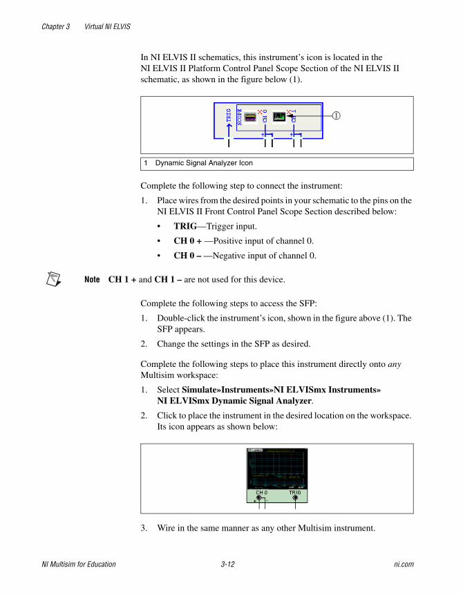
In NI ELVIS II schematics, this instrument’s icon is located in the NI ELVIS II Platform Control Panel Scope Section of the NI ELVIS II schematic, as shown in the figure below (1).
Complete the following step to connect the instrument:
1. Place wires from the desired points in your schematic to the pins on the NI ELVIS II Front Control Panel Scope Section described below:
• TRIG—Trigger input.
• CH 0 + —Positive input of channel 0.
• CH 0 – —Negative input of channel 0.
Note CH 1 + and CH 1 – are not used for this device.
Complete the following steps to access the SFP:
1. Double-click the instrument’s icon, shown in the figure above (1). The SFP appears.
2. Change the settings in the SFP as desired.
Complete the following steps to place this instrument directly onto any Multisim workspace:
1. Select Simulate»Instruments»NI ELVISmx Instruments»NI ELVISmx Dynamic Signal Analyzer.
2. Click to place the instrument in the desired location on the workspace. Its icon appears as shown below:
3. Wire in the same manner as any other Multisim instrument.
1 Dynamic Signal Analyzer Icon
Chapter 3 Virtual NI ELVIS
© National Instruments Corporation 3-13 NI Multisim for Education
Note You can also use the NI ELVISmx Instruments toolbar to place this instrument. Refer to the NI ELVISmx Instruments Toolbar section for more information.
For information about using this instrument, click the Help button on its SFP to display the NI ELVIS help file.
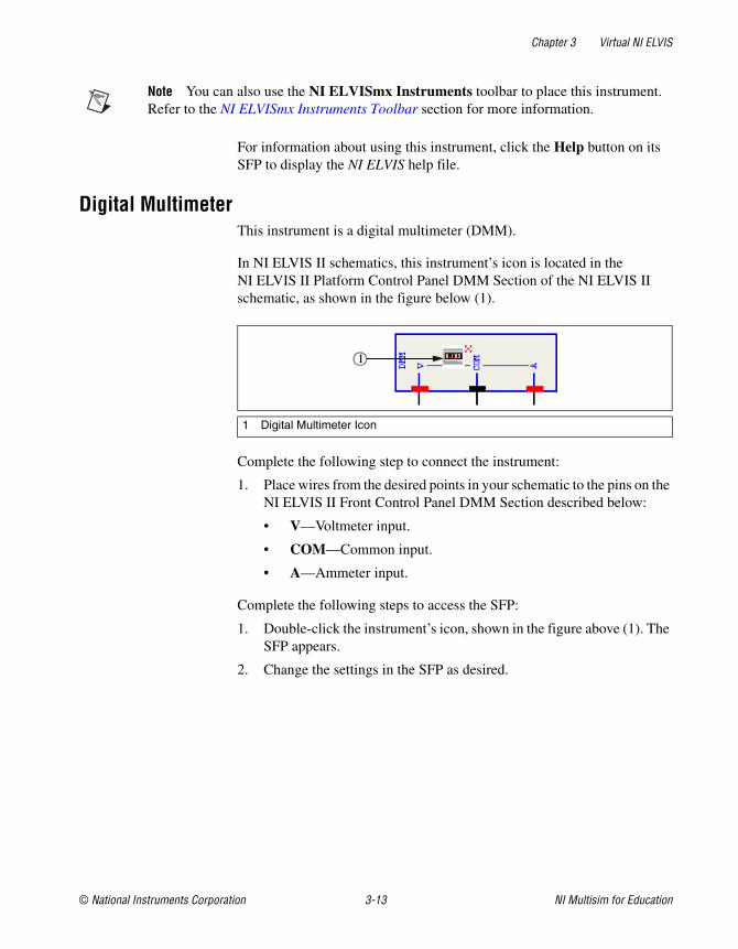
Digital Multimeter This instrument is a digital multimeter (DMM).
In NI ELVIS II schematics, this instrument’s icon is located in the NI ELVIS II Platform Control Panel DMM Section of the NI ELVIS II schematic, as shown in the figure below (1).
Complete the following step to connect the instrument:
1. Place wires from the desired points in your schematic to the pins on the NI ELVIS II Front Control Panel DMM Section described below:
• V—Voltmeter input.
• COM—Common input.
• A—Ammeter input.
Complete the following steps to access the SFP:
1. Double-click the instrument’s icon, shown in the figure above (1). The SFP appears.
2. Change the settings in the SFP as desired.
1 Digital Multimeter Icon
Chapter 3 Virtual NI ELVIS
NI Multisim for Education 3-14 ni.com
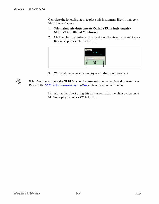
Complete the following steps to place this instrument directly onto any Multisim workspace:
1. Select Simulate»Instruments»NI ELVISmx Instruments»NI ELVISmx Digital Multimeter.
2. Click to place the instrument in the desired location on the workspace. Its icon appears as shown below:
3. Wire in the same manner as any other Multisim instrument.
Note You can also use the NI ELVISmx Instruments toolbar to place this instrument. Refer to the NI ELVISmx Instruments Toolbar section for more information.
For information about using this instrument, click the Help button on its SFP to display the NI ELVIS help file.
Chapter 3 Virtual NI ELVIS
© National Instruments Corporation 3-15 NI Multisim for Education
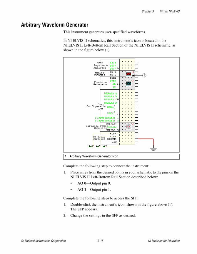
Arbitrary Waveform Generator This instrument generates user-specified waveforms.
In NI ELVIS II schematics, this instrument’s icon is located in the NI ELVIS II Left-Bottom Rail Section of the NI ELVIS II schematic, as shown in the figure below (1).
Complete the following step to connect the instrument:
1. Place wires from the desired points in your schematic to the pins on the NI ELVIS II Left-Bottom Rail Section described below:
• AO 0—Output pin 0.
• AO 1—Output pin 1.
Complete the following steps to access the SFP:
1. Double-click the instrument’s icon, shown in the figure above (1). The SFP appears.
2. Change the settings in the SFP as desired.
1 Arbitrary Waveform Generator Icon
Chapter 3 Virtual NI ELVIS
NI Multisim for Education 3-16 ni.com
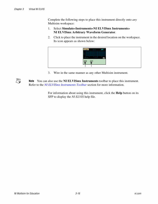
Complete the following steps to place this instrument directly onto any Multisim workspace:
1. Select Simulate»Instruments»NI ELVISmx Instruments»NI ELVISmx Arbitrary Waveform Generator.
2. Click to place the instrument in the desired location on the workspace. Its icon appears as shown below:
3. Wire in the same manner as any other Multisim instrument.
Note You can also use the NI ELVISmx Instruments toolbar to place this instrument. Refer to the NI ELVISmx Instruments Toolbar section for more information.
For information about using this instrument, click the Help button on its SFP to display the NI ELVIS help file.
Chapter 3 Virtual NI ELVIS
© National Instruments Corporation 3-17 NI Multisim for Education
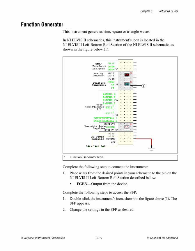
Function Generator This instrument generates sine, square or triangle waves.
In NI ELVIS II schematics, this instrument’s icon is located in the NI ELVIS II Left-Bottom Rail Section of the NI ELVIS II schematic, as shown in the figure below (1).
Complete the following step to connect the instrument:
1. Place wires from the desired points in your schematic to the pin on the NI ELVIS II Left-Bottom Rail Section described below:
• FGEN—Output from the device.
Complete the following steps to access the SFP:
1. Double-click the instrument’s icon, shown in the figure above (1). The SFP appears.
2. Change the settings in the SFP as desired.
1 Function Generator Icon
Chapter 3 Virtual NI ELVIS
NI Multisim for Education 3-18 ni.com
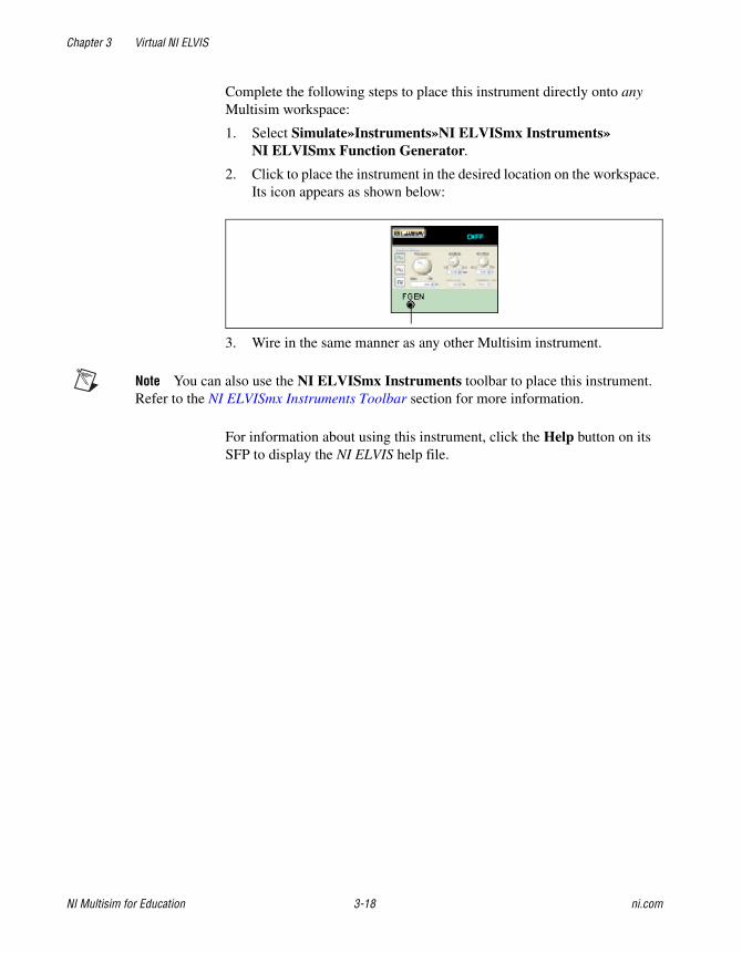
Complete the following steps to place this instrument directly onto any Multisim workspace:
1. Select Simulate»Instruments»NI ELVISmx Instruments»NI ELVISmx Function Generator.
2. Click to place the instrument in the desired location on the workspace. Its icon appears as shown below:
3. Wire in the same manner as any other Multisim instrument.
Note You can also use the NI ELVISmx Instruments toolbar to place this instrument. Refer to the NI ELVISmx Instruments Toolbar section for more information.
For information about using this instrument, click the Help button on its SFP to display the NI ELVIS help file.
Chapter 3 Virtual NI ELVIS
© National Instruments Corporation 3-19 NI Multisim for Education
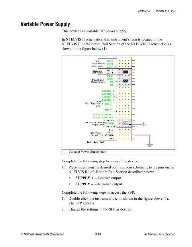
Variable Power Supply This device is a variable DC power supply.
In NI ELVIS II schematics, this instrument’s icon is located in the NI ELVIS II Left-Bottom Rail Section of the NI ELVIS II schematic, as shown in the figure below (1).
Complete the following step to connect the device:
1. Place wires from the desired points in your schematic to the pins on the NI ELVIS II Left-Bottom Rail Section described below:
• SUPPLY + —Positive output.
• SUPPLY – —Negative output.
Complete the following steps to access the SFP:
1. Double-click the instrument’s icon, shown in the figure above (1). The SFP appears.
2. Change the settings in the SFP as desired.
1 Variable Power Supply Icon
Chapter 3 Virtual NI ELVIS
NI Multisim for Education 3-20 ni.com
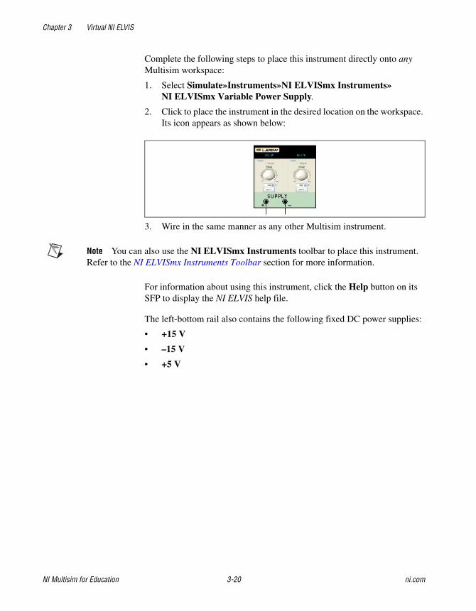
Complete the following steps to place this instrument directly onto any Multisim workspace:
1. Select Simulate»Instruments»NI ELVISmx Instruments»NI ELVISmx Variable Power Supply.
2. Click to place the instrument in the desired location on the workspace. Its icon appears as shown below:
3. Wire in the same manner as any other Multisim instrument.
Note You can also use the NI ELVISmx Instruments toolbar to place this instrument. Refer to the NI ELVISmx Instruments Toolbar section for more information.
For information about using this instrument, click the Help button on its SFP to display the NI ELVIS help file.
The left-bottom rail also contains the following fixed DC power supplies:
• +15 V
• –15 V
• +5 V

Chapter 3 Virtual NI ELVIS
© National Instruments Corporation 3-21 NI Multisim for Education
Digital Reader This instrument reads digital data.
In NI ELVIS II schematics, this instrument’s icon is located in the NI ELVIS II Right-Top Rail Section of the NI ELVIS II schematic, as shown in the figure below (1).
Complete the following step to connect the instrument:
1. Place wires from the desired points in your schematic to the pins on the NI ELVIS II Right-Top Rail Section described below:
• DIO 8 - DIO 15—The inputs for the device.
Complete the following steps to access the SFP:
1. Double-click the instrument’s icon, shown in the figure above (1). The SFP appears.
2. Change the settings in the SFP as desired.
1 Digital Reader Icon
Chapter 3 Virtual NI ELVIS
NI Multisim for Education 3-22 ni.com
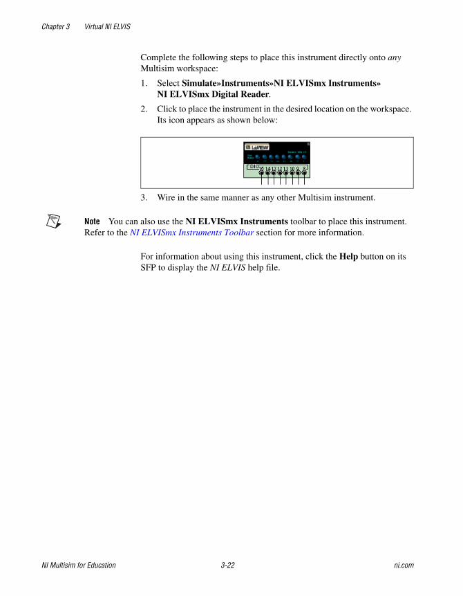
Complete the following steps to place this instrument directly onto any Multisim workspace:
1. Select Simulate»Instruments»NI ELVISmx Instruments»NI ELVISmx Digital Reader.
2. Click to place the instrument in the desired location on the workspace. Its icon appears as shown below:
3. Wire in the same manner as any other Multisim instrument.
Note You can also use the NI ELVISmx Instruments toolbar to place this instrument. Refer to the NI ELVISmx Instruments Toolbar section for more information.
For information about using this instrument, click the Help button on its SFP to display the NI ELVIS help file.

Chapter 3 Virtual NI ELVIS
© National Instruments Corporation 3-23 NI Multisim for Education
Digital Writer This instrument updates the digital output on the NI ELVIS Prototyping Board with user-specific digital patterns.
In NI ELVIS II schematics, this instrument’s icon is located in the NI ELVIS II Right-Top Rail Section of the NI ELVIS II schematic, as shown in the figure below (1).
Complete the following step to connect the instrument:
1. Place wires from the desired points in your schematic to the pins on the NI ELVIS II Right-Top Rail Section described below:
• DIO 0 - DIO 7—The outputs for the device.
Complete the following steps to access the SFP:
1. Double-click the instrument’s icon, shown in the figure above (1). The SFP appears.
2. Change the settings in the SFP as desired.
1 Digital Writer Icon
Chapter 3 Virtual NI ELVIS
NI Multisim for Education 3-24 ni.com
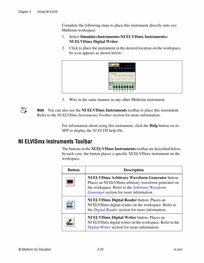
Complete the following steps to place this instrument directly onto any Multisim workspace:
1. Select Simulate»Instruments»NI ELVISmx Instruments»NI ELVISmx Digital Writer.
2. Click to place the instrument in the desired location on the workspace. Its icon appears as shown below:
3. Wire in the same manner as any other Multisim instrument.
Note You can also use the NI ELVISmx Instruments toolbar to place this instrument. Refer to the NI ELVISmx Instruments Toolbar section for more information.
For information about using this instrument, click the Help button on its SFP to display the NI ELVIS help file.
NI ELVISmx Instruments Toolbar The buttons in the NI ELVISmx Instruments toolbar are described below. In each case, the button places a specific NI ELVISmx instrument on the workspace.
Button Description
NI ELVISmx Arbitrary Waveform Generator button. Places an NI ELVISmx arbitrary waveform generator on the workspace. Refer to the Arbitrary Waveform Generator section for more information.
NI ELVISmx Digital Reader button. Places an NI ELVISmx digital reader on the workspace. Refer to the Digital Reader section for more information.
NI ELVISmx Digital Writer button. Places an NI ELVISmx digital writer on the workspace. Refer to the Digital Writer section for more information.

Chapter 3 Virtual NI ELVIS
© National Instruments Corporation 3-25 NI Multisim for Education
The Virtual NI ELVIS II Schematic A virtual NI ELVIS II schematic contains a number of items that correspond to elements of the real-world NI ELVIS II workstation. The connection and control of these elements is described in this section.
Note This section describes the behavior of Multisim’s NI ELVIS II schematic. Refer to The Virtual NI ELVIS I Schematic section for information on Multisim’s original NI ELVIS I functionality.
Complete the following steps to create a new virtual NI ELVIS II schematic:
1. Select File»New»NI ELVIS II Schematic. When first opened, a virtual NI ELVIS II schematic appears as shown below.
NI ELVISmx Digital Multimeter button. Places an NI ELVISmx digital multimeter on the workspace. Refer to the Digital Multimeter section for more information.
NI ELVISmx Dynamic Signal Analyzer button. Places an NI ELVISmx dynamic signal analyzer on the workspace. Refer to the Dynamic Signal Analyzer section for more information.
NI ELVISmx Function Generator button. Places an NI ELVISmx function generator on the workspace. Refer to the Function Generator section for more information.
NI ELVISmx Oscilloscope button. Places an NI ELVISmx oscilloscope on the workspace. Refer to the Oscilloscope section for more information.
NI ELVISmx Variable Power Supply button. Places an NI ELVISmx variable power supply on the workspace. Refer to the Variable Power Supply section for more information.
Button Description
Chapter 3 Virtual NI ELVIS
NI Multisim for Education 3-26 ni.com
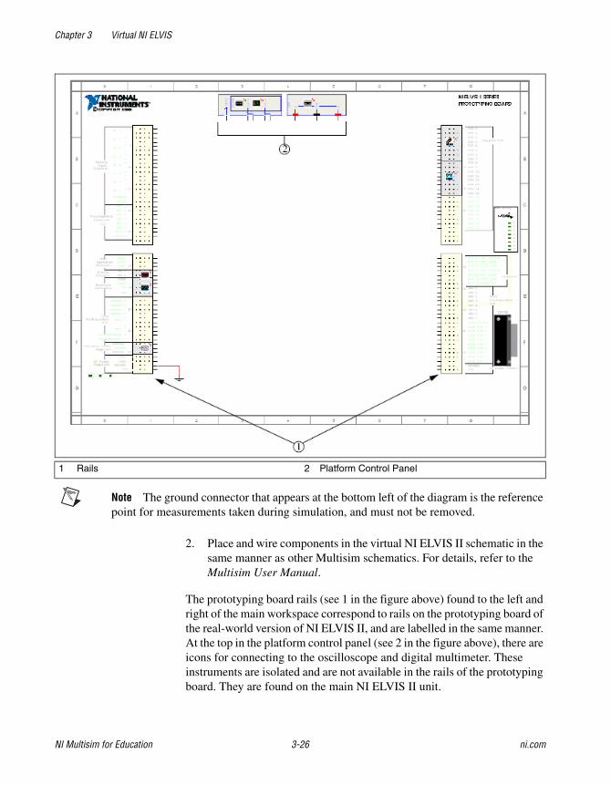
Note The ground connector that appears at the bottom left of the diagram is the reference point for measurements taken during simulation, and must not be removed.
2. Place and wire components in the virtual NI ELVIS II schematic in the same manner as other Multisim schematics. For details, refer to the Multisim User Manual.
The prototyping board rails (see 1 in the figure above) found to the left and right of the main workspace correspond to rails on the prototyping board of the real-world version of NI ELVIS II, and are labelled in the same manner. At the top in the platform control panel (see 2 in the figure above), there are icons for connecting to the oscilloscope and digital multimeter. These instruments are isolated and are not available in the rails of the prototyping board. They are found on the main NI ELVIS II unit.
1 Rails 2 Platform Control Panel
Chapter 3 Virtual NI ELVIS
© National Instruments Corporation 3-27 NI Multisim for Education
Rows on the rails that are shown with green labels are not enabled for simulation in Multisim. However, they can be used for schematic capture and viewing of the completed virtual NI ELVIS II schematic in the 3D view.
Unlike other Multisim components, these rails and instrument icons cannot be moved to other places on the workspace.
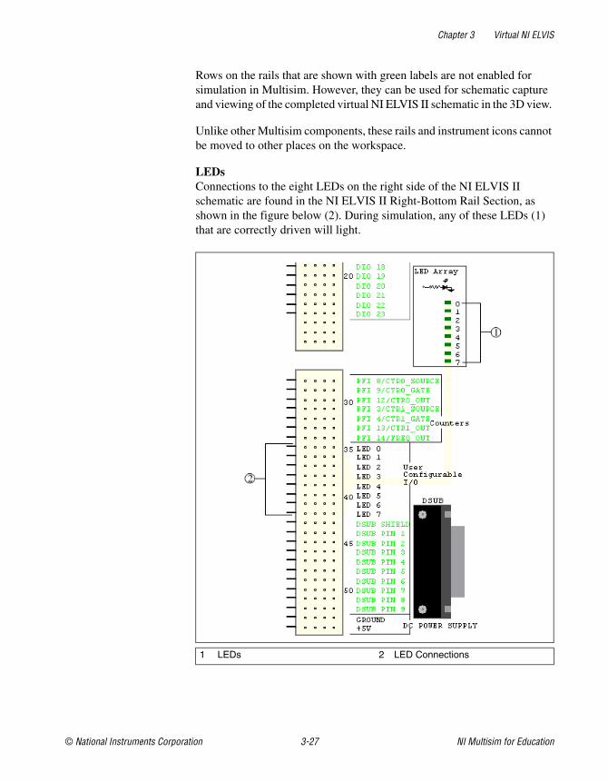
LEDsConnections to the eight LEDs on the right side of the NI ELVIS II schematic are found in the NI ELVIS II Right-Bottom Rail Section, as shown in the figure below (2). During simulation, any of these LEDs (1) that are correctly driven will light.
1 LEDs 2 LED Connections

Chapter 3 Virtual NI ELVIS
NI Multisim for Education 3-28 ni.com
Complete the following to connect to an LED:
1. Place a wire from one of the LED rows (LED 0 through LED 7) to the desired point in your schematic.
There are also three power supply LEDs in the lower-left section of any virtual NI ELVIS II schematic, as shown in the figure below (1):
During simulation, these LEDs will light whether or not connections have been made to their corresponding pins in the prototyping rail. They indicate that power is available to the respective connections.
Enabling NI ELVIS II Schematic Instruments for Simulation NI ELVISmx instruments on the NI ELVIS II schematic can be enabled or disabled for simulation on an individual basis. Each enabled instrument consumes system resources, so setting unused instruments to disabled will improve simulation speed.
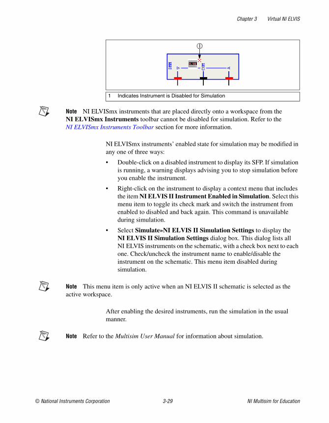
When an NI ELVISmx instrument is disabled, a small red “X” appears next to the upper-right corner of the instrument icon on the schematic, as shown in the figure below (1). By default, all instruments in a new NI ELVIS II schematic begin as disabled.
1 Power Supply LEDs
Chapter 3 Virtual NI ELVIS
© National Instruments Corporation 3-29 NI Multisim for Education
Note NI ELVISmx instruments that are placed directly onto a workspace from the NI ELVISmx Instruments toolbar cannot be disabled for simulation. Refer to theNI ELVISmx Instruments Toolbar section for more information.
NI ELVISmx instruments’ enabled state for simulation may be modified in any one of three ways:
• Double-click on a disabled instrument to display its SFP. If simulation is running, a warning displays advising you to stop simulation before you enable the instrument.
• Right-click on the instrument to display a context menu that includes the item NI ELVIS II Instrument Enabled in Simulation. Select this menu item to toggle its check mark and switch the instrument from enabled to disabled and back again. This command is unavailable during simulation.
• Select Simulate»NI ELVIS II Simulation Settings to display the NI ELVIS II Simulation Settings dialog box. This dialog lists all NI ELVIS instruments on the schematic, with a check box next to each one. Check/uncheck the instrument name to enable/disable the instrument on the schematic. This menu item disabled during simulation.
Note This menu item is only active when an NI ELVIS II schematic is selected as the active workspace.
After enabling the desired instruments, run the simulation in the usual manner.
Note Refer to the Multisim User Manual for information about simulation.
1 Indicates Instrument is Disabled for Simulation
Chapter 3 Virtual NI ELVIS
NI Multisim for Education 3-30 ni.com
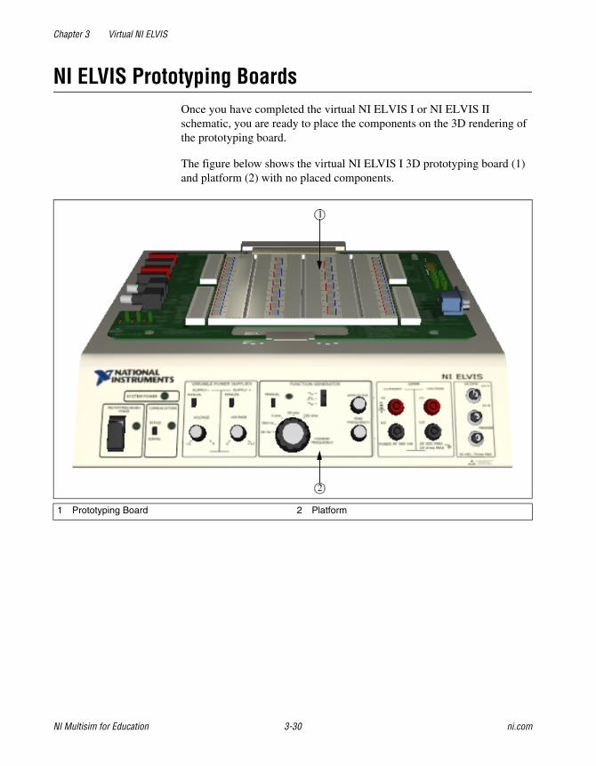
NI ELVIS Prototyping Boards Once you have completed the virtual NI ELVIS I or NI ELVIS II schematic, you are ready to place the components on the 3D rendering of the prototyping board.
The figure below shows the virtual NI ELVIS I 3D prototyping board (1) and platform (2) with no placed components.
1 Prototyping Board 2 Platform

Chapter 3 Virtual NI ELVIS
© National Instruments Corporation 3-31 NI Multisim for Education
The figure below shows the virtual NI ELVIS II 3D prototyping board (1) and platform (2) with no placed components.
Note The controls that appear on the NI ELVIS I and the NI ELVIS II 3D platforms are inactive. Interactive simulation is accomplished via the schematic view. For details on simulation, refer to the Multisim User Manual or the Multisim help file.
Tip For information about changing the 3D view, refer to the Manipulating the Breadboard View section of Chapter 2, Breadboarding.
1 Prototyping Board 2 Platform
Chapter 3 Virtual NI ELVIS
NI Multisim for Education 3-32 ni.com
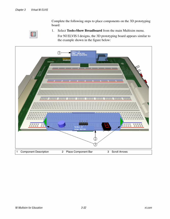
Complete the following steps to place components on the 3D prototyping board:
1. Select Tools»Show Breadboard from the main Multisim menu.
For NI ELVIS I designs, the 3D prototyping board appears similar to the example shown in the figure below:
1 Component Description 2 Place Component Bar 3 Scroll Arrows
Chapter 3 Virtual NI ELVIS
© National Instruments Corporation 3-33 NI Multisim for Education
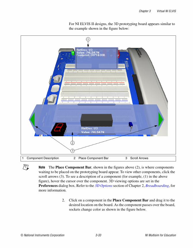
For NI ELVIS II designs, the 3D prototyping board appears similar to the example shown in the figure below:
Note The Place Component Bar, shown in the figures above (2), is where components waiting to be placed on the prototyping board appear. To view other components, click the scroll arrows (3). To see a description of a component (for example, (1) in the above figure), hover the cursor over the component. 3D viewing options are set in the Preferences dialog box. Refer to the 3D Options section of Chapter 2, Breadboarding, for more information.
2. Click on a component in the Place Component Bar and drag it to the desired location on the board. As the component passes over the board, sockets change color as shown in the figure below.
1 Component Description 2 Place Component Bar 3 Scroll Arrows
Chapter 3 Virtual NI ELVIS
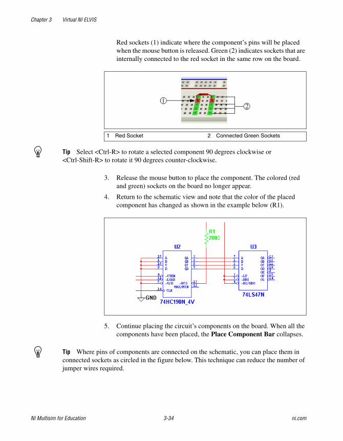
NI Multisim for Education 3-34 ni.com
Red sockets (1) indicate where the component’s pins will be placed when the mouse button is released. Green (2) indicates sockets that are internally connected to the red socket in the same row on the board.
Tip Select <Ctrl-R> to rotate a selected component 90 degrees clockwise or <Ctrl-Shift-R> to rotate it 90 degrees counter-clockwise.
3. Release the mouse button to place the component. The colored (red and green) sockets on the board no longer appear.
4. Return to the schematic view and note that the color of the placed component has changed as shown in the example below (R1).
5. Continue placing the circuit’s components on the board. When all the components have been placed, the Place Component Bar collapses.
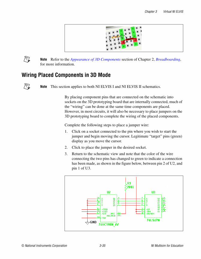
Tip Where pins of components are connected on the schematic, you can place them in connected sockets as circled in the figure below. This technique can reduce the number of jumper wires required.
1 Red Socket 2 Connected Green Sockets
Chapter 3 Virtual NI ELVIS
© National Instruments Corporation 3-35 NI Multisim for Education
Note Refer to the Appearance of 3D Components section of Chapter 2, Breadboarding, for more information.
Wiring Placed Components in 3D Mode
Note This section applies to both NI ELVIS I and NI ELVIS II schematics.
By placing component pins that are connected on the schematic into sockets on the 3D prototyping board that are internally connected, much of the “wiring” can be done at the same time components are placed. However, in most circuits, it will also be necessary to place jumpers on the 3D prototyping board to complete the wiring of the placed components.
Complete the following steps to place a jumper wire:
1. Click on a socket connected to the pin where you wish to start the jumper and begin moving the cursor. Legitimate “target” pins (green) display as you move the cursor.
2. Click to place the jumper in the desired socket.
3. Return to the schematic view and note that the color of the wire connecting the two pins has changed to green to indicate a connection has been made, as shown in the figure below, between pin 2 of U2, and pin 1 of U3.
Chapter 3 Virtual NI ELVIS
NI Multisim for Education 3-36 ni.com
Note If a net contains more than two connections, all must be connected before any of the wires in the net change color.
4. Continue placing jumpers until all schematic connections have been made.
Tip Run a Design Rules and Connectivity Check from the 3D prototyping view to see if there are any errors in your board. Refer to the DRC and Connectivity Check section of Chapter 2, Breadboarding, for more information.
Note You may also wish to refer to the Viewing Component Information and Breadboard Netlist dialog box sections of Chapter 2, Breadboarding.
© National Instruments Corporation 4-1 NI Multisim for Education
4Ladder Diagrams
This chapter describes the ladder diagram functionality that Multisim contains.
Some of the features described in this chapter may not be available in your edition of Multisim. Refer to the release notes for a description of the features available in your edition.
OverviewThe Education edition of Multisim lets you capture and simulate Ladder Diagrams. These diagrams are electrically based, as opposed to the binary/digital representations employed by ladder logic. Diagrams of this type are used extensively for industrial motor control circuits.
Ladder Diagrams are able to drive output devices or take input data from regular schematics and embed the instructions on how input states affect output states in either the same schematic or separate hierarchical blocks or subcircuits that contain the Ladder Diagram.
Note Refer to the Multisim User Manual for a complete description of hierarchical blocks and subcircuits.
Creating a Ladder DiagramThis section describes the steps required to make a simple Ladder Diagram. The concepts described here should be understood before reviewing the more complex circuits found in this chapter.
This section describes how to build the Ladder Diagram that is reviewed in the AND Rungs and OR Rungs section.

Chapter 4 Ladder Diagrams
NI Multisim for Education 4-2 ni.com
Note Refer to the Component Reference help file for details on ladder diagram components.
Circuit Notes:
• The relays (X1-X4) are normally open relays. When their controlling coils (M1or M2) are energized they close. The controlling coils are set in the Value tab of each relay’s properties dialog box. Refer to the Component Reference help file for more information.
• Both X1 AND X2 must be closed for the lamp in the AND rung (X5) to light up.
• Either X3 OR X4 must be closed for the lamp in the OR rung (X6) to light up.
• Coil M1 controls the relays with M1 as their reference. (X1 and X3.)
• Coil M2 controls the relays with M2 as their reference. (X2 and X4.)
• Use keys 1 and 2 on your keyboard to open and close switches J1 and J2, or hover your cursor over the desired switch and click on the button that pops up.
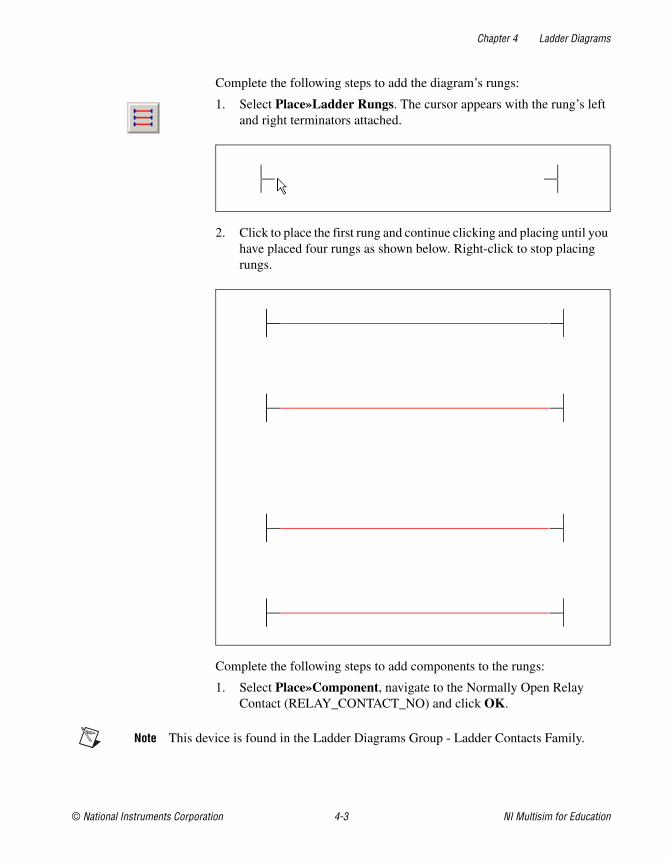
Chapter 4 Ladder Diagrams
© National Instruments Corporation 4-3 NI Multisim for Education
Complete the following steps to add the diagram’s rungs:
1. Select Place»Ladder Rungs. The cursor appears with the rung’s left and right terminators attached.
2. Click to place the first rung and continue clicking and placing until you have placed four rungs as shown below. Right-click to stop placing rungs.
Complete the following steps to add components to the rungs:
1. Select Place»Component, navigate to the Normally Open Relay Contact (RELAY_CONTACT_NO) and click OK.
Note This device is found in the Ladder Diagrams Group - Ladder Contacts Family.

Chapter 4 Ladder Diagrams
NI Multisim for Education 4-4 ni.com
2. Drop the relay contact directly onto the first rung.
3. Continue in this manner until all relay contacts have been placed. (X4 must be placed and then wired separately.)
4. Place the lamps (Group - Indicators; Family - Lamp).
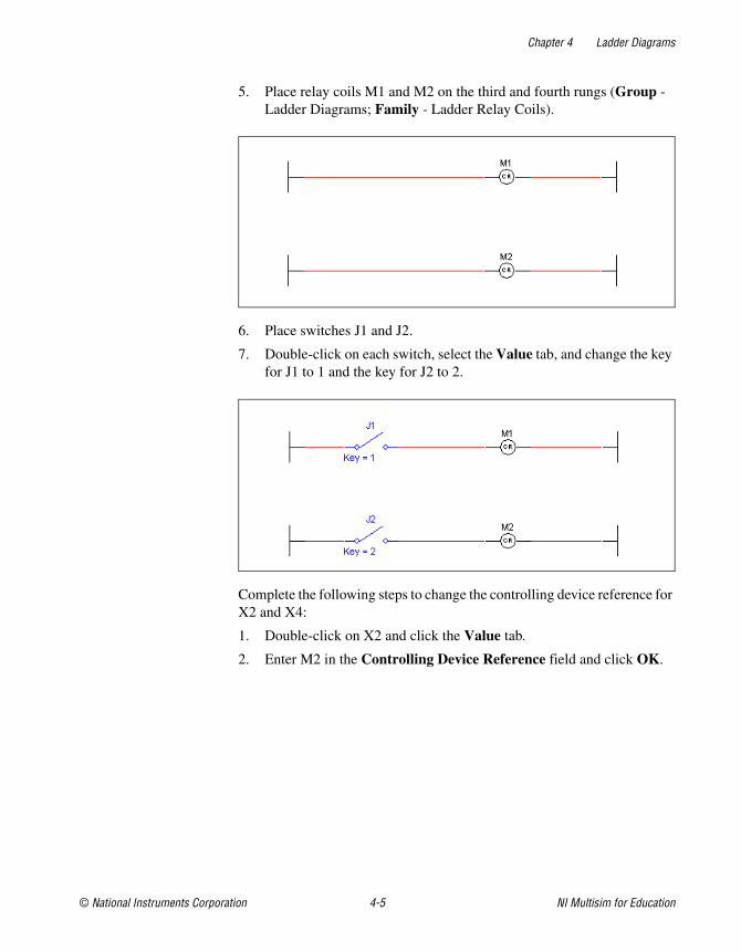
Chapter 4 Ladder Diagrams
© National Instruments Corporation 4-5 NI Multisim for Education
5. Place relay coils M1 and M2 on the third and fourth rungs (Group - Ladder Diagrams; Family - Ladder Relay Coils).
6. Place switches J1 and J2.
7. Double-click on each switch, select the Value tab, and change the key for J1 to 1 and the key for J2 to 2.
Complete the following steps to change the controlling device reference for X2 and X4:
1. Double-click on X2 and click the Value tab.
2. Enter M2 in the Controlling Device Reference field and click OK.

Chapter 4 Ladder Diagrams
NI Multisim for Education 4-6 ni.com
Repeat for X4. The completed Ladder Diagram appears as shown below.
AND Rungs and OR Rungs This section illustrates the difference between AND rungs and OR rungs that are found in Ladder Diagrams. The concepts described here should be understood before reviewing the more complex circuits found in this chapter.

Chapter 4 Ladder Diagrams
© National Instruments Corporation 4-7 NI Multisim for Education
Complete the following steps to activate the lamp in the OR rung:
1. Select Simulate»Run to start simulation of the circuit.
2. Press <1> on your keyboard to close J1 (or hover your cursor over J1 and click the button that pops up). Lamp X6 lights as described below.
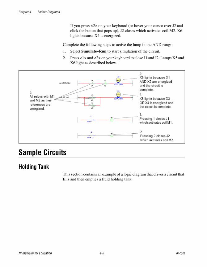
Chapter 4 Ladder Diagrams
NI Multisim for Education 4-8 ni.com
If you press <2> on your keyboard (or hover your cursor over J2 and click the button that pops up), J2 closes which activates coil M2. X6 lights because X4 is energized.
Complete the following steps to active the lamp in the AND rung:
1. Select Simulate»Run to start simulation of the circuit.
2. Press <1> and <2> on your keyboard to close J1 and J2. Lamps X5 and X6 light as described below.
Sample Circuits
Holding TankThis section contains an example of a logic diagram that drives a circuit that fills and then empties a fluid holding tank.
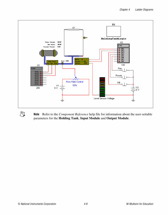
Chapter 4 Ladder Diagrams
© National Instruments Corporation 4-9 NI Multisim for Education
Note Refer to the Component Reference help file for information about the user-settable parameters for the Holding Tank, Input Module and Output Module.
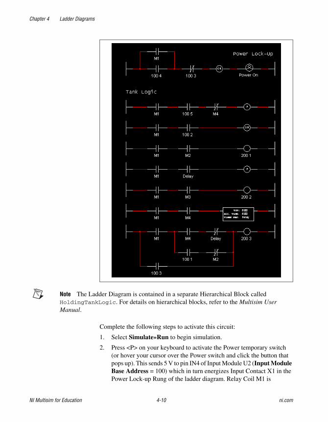
Chapter 4 Ladder Diagrams
NI Multisim for Education 4-10 ni.com
Note The Ladder Diagram is contained in a separate Hierarchical Block called HoldingTankLogic. For details on hierarchical blocks, refer to the Multisim User Manual.
Complete the following steps to activate this circuit:
1. Select Simulate»Run to begin simulation.
2. Press <P> on your keyboard to activate the Power temporary switch (or hover your cursor over the Power switch and click the button that pops up). This sends 5 V to pin IN4 of Input Module U2 (Input Module Base Address = 100) which in turn energizes Input Contact X1 in the Power Lock-up Rung of the ladder diagram. Relay Coil M1 is

Chapter 4 Ladder Diagrams
© National Instruments Corporation 4-11 NI Multisim for Education
energized, causing all Relay Contacts with Relay Device Reference = M1 to energize.
Complete the following steps to run the holding tank circuit:
1. Activate the circuit as described above.
2. Press <R> on your keyboard (or hover your cursor over the Run switch and click the button that pops up) to activate the Run temporary switch.
Tip Select Window»Tile Vertical to view the ladder diagram and the circuit at the same time. Observe the interaction between the ladder diagram and the circuit as the simulation proceeds.
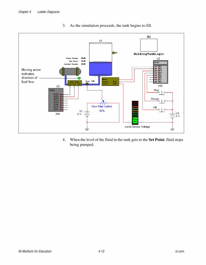
Chapter 4 Ladder Diagrams
NI Multisim for Education 4-12 ni.com
3. As the simulation proceeds, the tank begins to fill.
4. When the level of the fluid in the tank gets to the Set Point, fluid stops being pumped.
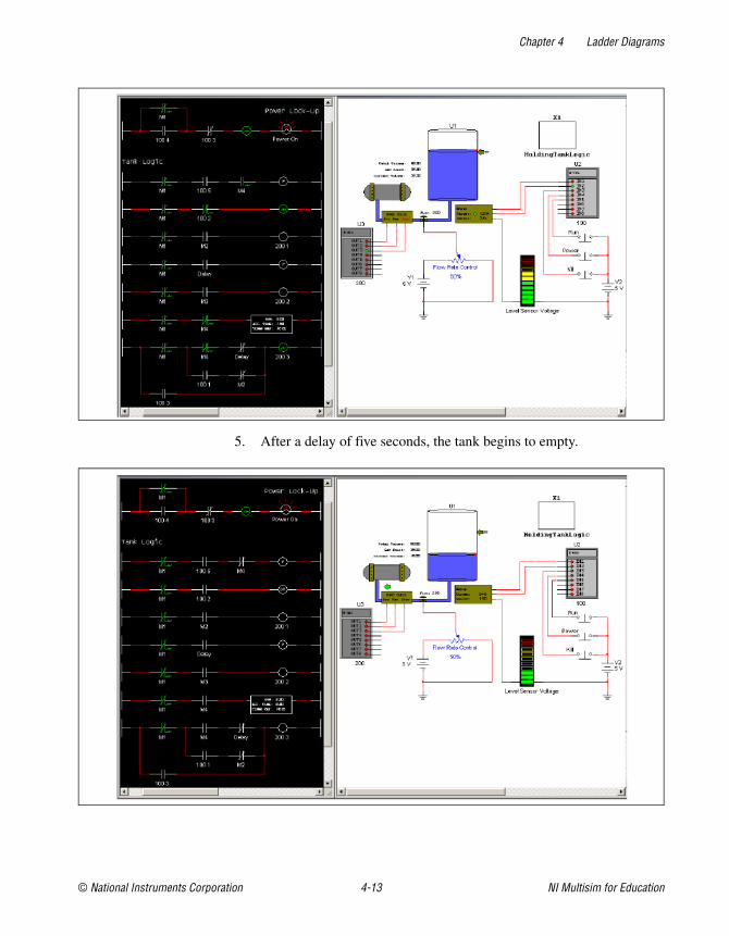
Chapter 4 Ladder Diagrams
© National Instruments Corporation 4-13 NI Multisim for Education
5. After a delay of five seconds, the tank begins to empty.
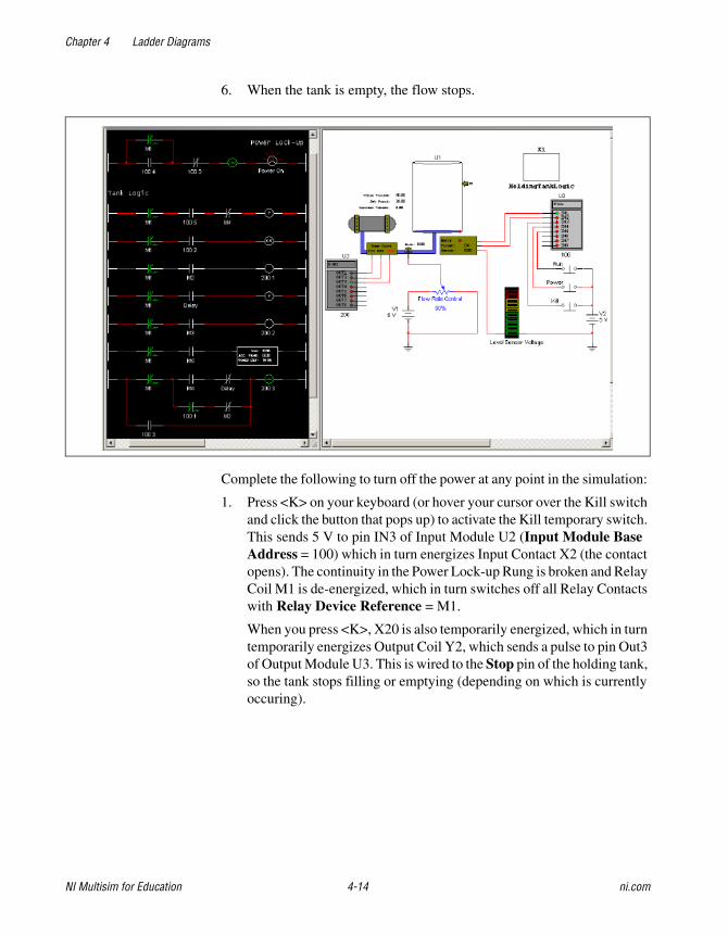
Chapter 4 Ladder Diagrams
NI Multisim for Education 4-14 ni.com
6. When the tank is empty, the flow stops.
Complete the following to turn off the power at any point in the simulation:
1. Press <K> on your keyboard (or hover your cursor over the Kill switch and click the button that pops up) to activate the Kill temporary switch. This sends 5 V to pin IN3 of Input Module U2 (Input Module Base Address = 100) which in turn energizes Input Contact X2 (the contact opens). The continuity in the Power Lock-up Rung is broken and Relay Coil M1 is de-energized, which in turn switches off all Relay Contacts with Relay Device Reference = M1.
When you press <K>, X20 is also temporarily energized, which in turn temporarily energizes Output Coil Y2, which sends a pulse to pin Out3 of Output Module U3. This is wired to the Stop pin of the holding tank, so the tank stops filling or emptying (depending on which is currently occuring).
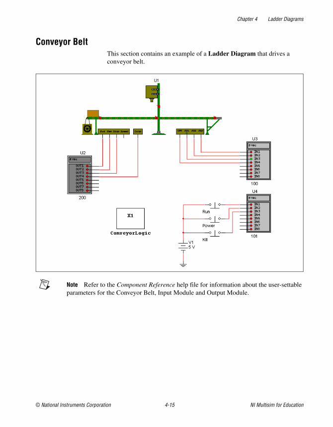
Chapter 4 Ladder Diagrams
© National Instruments Corporation 4-15 NI Multisim for Education
Conveyor BeltThis section contains an example of a Ladder Diagram that drives a conveyor belt.
Note Refer to the Component Reference help file for information about the user-settable parameters for the Conveyor Belt, Input Module and Output Module.
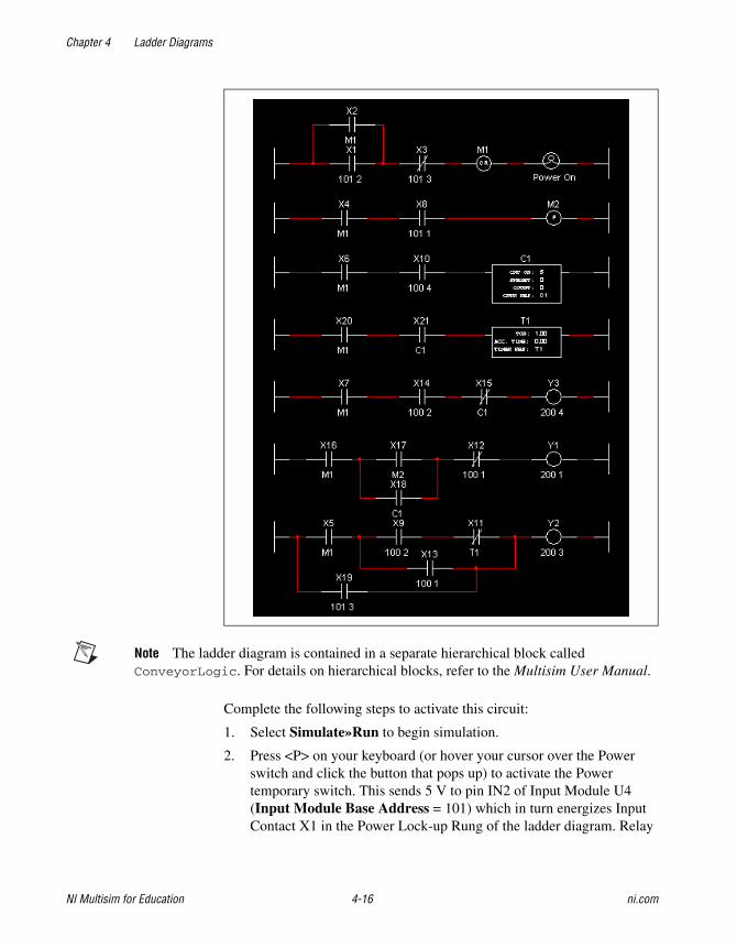
Chapter 4 Ladder Diagrams
NI Multisim for Education 4-16 ni.com
Note The ladder diagram is contained in a separate hierarchical block called ConveyorLogic. For details on hierarchical blocks, refer to the Multisim User Manual.
Complete the following steps to activate this circuit:
1. Select Simulate»Run to begin simulation.
2. Press <P> on your keyboard (or hover your cursor over the Power switch and click the button that pops up) to activate the Power temporary switch. This sends 5 V to pin IN2 of Input Module U4 (Input Module Base Address = 101) which in turn energizes Input Contact X1 in the Power Lock-up Rung of the ladder diagram. Relay
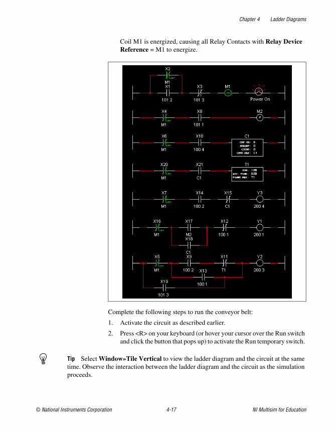
Chapter 4 Ladder Diagrams
© National Instruments Corporation 4-17 NI Multisim for Education
Coil M1 is energized, causing all Relay Contacts with Relay Device Reference = M1 to energize.
Complete the following steps to run the conveyor belt:
1. Activate the circuit as described earlier.
2. Press <R> on your keyboard (or hover your cursor over the Run switch and click the button that pops up) to activate the Run temporary switch.
Tip Select Window»Tile Vertical to view the ladder diagram and the circuit at the same time. Observe the interaction between the ladder diagram and the circuit as the simulation proceeds.
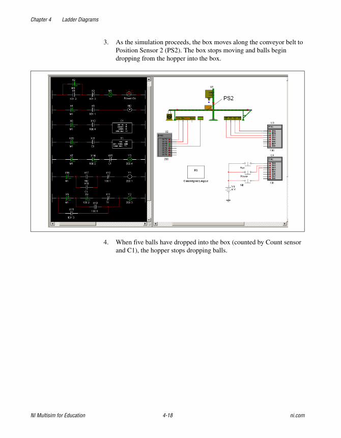
Chapter 4 Ladder Diagrams
NI Multisim for Education 4-18 ni.com
3. As the simulation proceeds, the box moves along the conveyor belt to Position Sensor 2 (PS2). The box stops moving and balls begin dropping from the hopper into the box.
4. When five balls have dropped into the box (counted by Count sensor and C1), the hopper stops dropping balls.
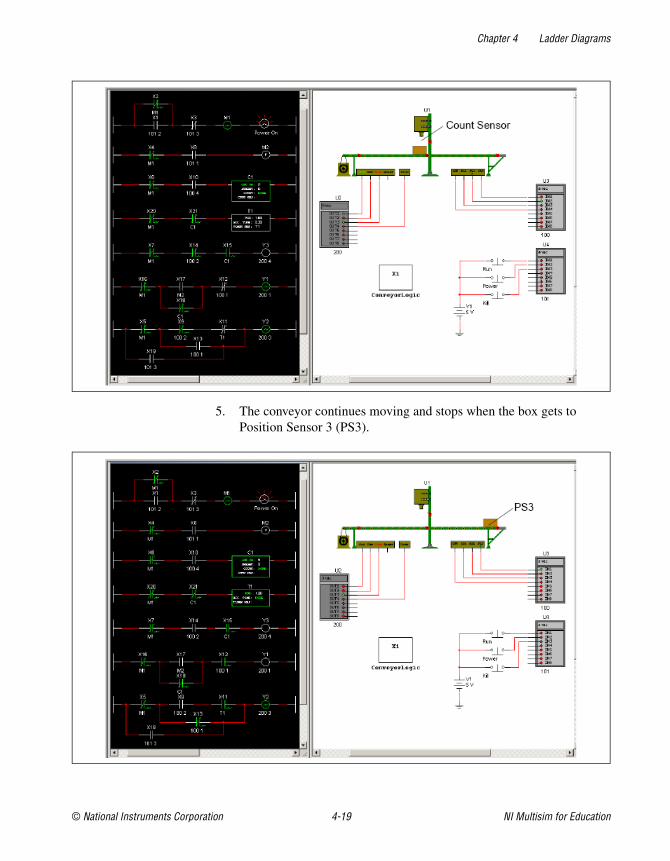
Chapter 4 Ladder Diagrams
© National Instruments Corporation 4-19 NI Multisim for Education
5. The conveyor continues moving and stops when the box gets to Position Sensor 3 (PS3).
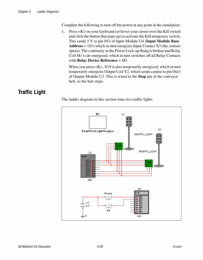
Chapter 4 Ladder Diagrams
NI Multisim for Education 4-20 ni.com
Complete the following to turn off the power at any point in the simulation:
1. Press <K> on your keyboard (or hover your cursor over the Kill switch and click the button that pops up) to activate the Kill temporary switch. This sends 5 V to pin IN3 of Input Module U4 (Input Module Base Address = 101) which in turn energizes Input Contact X3 (the contact opens). The continuity in the Power Lock-up Rung is broken and Relay Coil M1 is de-energized, which in turn switches off all Relay Contacts with Relay Device Reference = M1.
When you press <K>, X19 is also temporarily energized, which in turn temporarily energizes Output Coil Y2, which sends a pulse to pin Out3 of Output Module U2. This is wired to the Stop pin of the conveyor belt, so the belt stops.
Traffic LightThe ladder diagram in this section runs two traffic lights.

Chapter 4 Ladder Diagrams
© National Instruments Corporation 4-21 NI Multisim for Education
Note The ladder diagram is contained in a separate hierarchical block called TrafficLightLogic. For details on hierarchical blocks, refer to the Multisim User Manual.
Complete the following steps to run the traffic lights:
1. Select Simulate»Run.
2. Press <P> on your keyboard (or hover your cursor over the Power switch and click the button that pops up) to activate the Power momentary switch.
Tip Select Window»Tile Vertical to view the ladder diagram and the circuit at the same time. Observe the interaction between the ladder diagram and the circuit as the simulation proceeds.
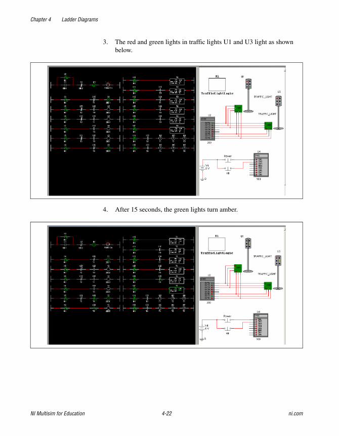
Chapter 4 Ladder Diagrams
NI Multisim for Education 4-22 ni.com
3. The red and green lights in traffic lights U1 and U3 light as shown below.
4. After 15 seconds, the green lights turn amber.
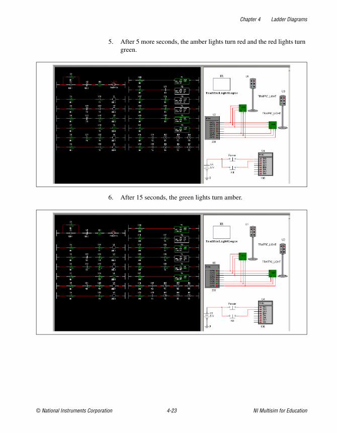
Chapter 4 Ladder Diagrams
© National Instruments Corporation 4-23 NI Multisim for Education
5. After 5 more seconds, the amber lights turn red and the red lights turn green.
6. After 15 seconds, the green lights turn amber.

Chapter 4 Ladder Diagrams
NI Multisim for Education 4-24 ni.com
7. After 5 more seconds, the amber lights turn red and the red lights turn green.
8. The cycle continues in this way until you stop the simulation, or press <K> (or hover your cursor over the Kill switch and click the button that pops up) to activate the Kill momentary switch.
© National Instruments Corporation A-1 NI Multisim for Education
ATechnical Support and Professional Services
Visit the following sections of the award-winning National Instruments Web site at ni.com for technical support and professional services:
• Support—Technical support resources at ni.com/support include the following:
– Self-Help Technical Resources—For answers and solutions, visit ni.com/support for software drivers and updates, a searchable KnowledgeBase, product manuals, step-by-step troubleshooting wizards, thousands of example programs, tutorials, application notes, instrument drivers, and so on. Registered users also receive access to the NI Discussion Forums at ni.com/forums. NI Applications Engineers make sure every question submitted online receives an answer.
– Standard Service Program Membership—This program entitles members to direct access to NI Applications Engineers via phone and email for one-to-one technical support as well as exclusive access to on demand training modules via the Services Resource Center. NI offers complementary membership for a full year after purchase, after which you may renew to continue your benefits.
For information about other technical support options in your area, visit ni.com/services, or contact your local office at ni.com/contact.
• Training and Certification—Visit ni.com/training for self-paced training, eLearning virtual classrooms, interactive CDs, and Certification program information. You also can register for instructor-led, hands-on courses at locations around the world.
• System Integration—If you have time constraints, limited in-house technical resources, or other project challenges, National Instruments Alliance Partner members can help. To learn more, call your local NI office or visit ni.com/alliance.

Appendix A Technical Support and Professional Services
NI Multisim for Education A-2 ni.com
If you searched ni.com and could not find the answers you need, contact your local office or NI corporate headquarters. Phone numbers for our worldwide offices are listed at the front of this manual. You also can visit the Worldwide Offices section of ni.com/niglobal to access the branch office Web sites, which provide up-to-date contact information, support phone numbers, email addresses, and current events.
© National Instruments Corporation I-1 NI Multisim for Education
Index
BBreadboard Netlist dialog box, 2-12Breadboard Settings, 2-1
Ccircuit restrictions
setting, 1-5conventions used in the manual, v
Ddiagnostic tools (NI resources), A-1documentation
conventions used in the manual, vNI resources, A-1
drivers (NI resources), A-1
Eexamples (NI resources), A-1
Gglobal restrictions
passwords, 1-7setting, 1-2
Hhelp, technical support, A-1
Iinstrument drivers (NI resources), A-1
KKnowledgeBase, A-1
NNational Instruments support
and services, A-1NI ELVIS II Simulation Settings
dialog box, 3-28NI ELVISmx Instruments toolbar, 3-24
Ppasswords, creating/changing, 1-7programming examples (NI resources), A-1
Rrestrictions
about, 1-2setting circuit, 1-5setting global, 1-2
Ssetting circuit restrictions, 1-5setting global restrictions, 1-2Simplified Version, 1-2software (NI resources), A-1Support, A-1support, technical, A-1
Index
NI Multisim for Education I-2 ni.com
Ttechnical support, A-1training and certification (NI resources), A-1troubleshooting (NI resources), A-1
VVirtual NI ELVIS
overview, 3-1Virtual NI ELVIS I
3D prototyping board, 3-30ammeter, 3-6function generator, 3-8instruments, 3-4IV Analyzer, 3-6oscilloscope, 3-5power supplies, 3-9prototyping board LEDs, 3-1schematic, 3-1Volt/Ohmmeter, 3-6wiring placed components in 3D, 3-35
Virtual NI ELVIS II3D prototyping board, 3-30arbitrary waveform generator, 3-15digital multimeter, 3-13digital reader, 3-21digital writer, 3-23dynamic signal analyzer, 3-11function generator, 3-17instruments, 3-9oscilloscope, 3-10prototyping board LEDs, 3-25schematic, 3-25simulation settings, 3-28variable power supply, 3-19
Virtual NI ELVIS II Instrumentssetting instruments to simulate, 3-28
WWeb resources, A-1