PRACTICAL USER’S GUIDE FOR THE DIMPLEX · PDF fileFOR THE DIMPLEX ELECTRIC FIREPLACE...
15
PRACTICAL USER’S GUIDE FOR THE DIMPLEX ELECTRIC FIREPLACE WITH REMOTE CONTROL Valued Customer, We are pleased that you have chosen to purchase an electric fireplace manufactured by Dimplex North America Ltd. Over the years, valuable memories will occur around the warmth and comfort of your hearth. Thank you for allowing our product to be the backdrop for those special moments. Quality checked by: 7206581100REV02 Serial Number _________________ Model Number _________________ CAT Number __________________
Transcript of PRACTICAL USER’S GUIDE FOR THE DIMPLEX · PDF fileFOR THE DIMPLEX ELECTRIC FIREPLACE...

PRACTICAL USER’S GUIDE FOR THE
DIMPLEX ELECTRIC FIREPLACE WITH REMOTE CONTROL
Valued Customer,
We are pleased that you have chosen to purchase an electric
fireplace manufactured by Dimplex North America Ltd.
Over the years, valuable memories will occur around the
warmth and comfort of your hearth. Thank you for allowing
our product to be the backdrop for those special moments.
Quality checked by:
7206581100REV02
Serial Number _________________
Model Number _________________
CAT Number __________________

QUICK REFERENCE GUIDE FOR THE DIMPLEX ELECTRIC FIREPLACE
1. Prior to the first use of the fireplace verify t he following: • Are the circuit breakers for the unit on? • Are the light bulbs in your fireplace loose? (to ch eck, follow the
instructions for replacing the light bulbs under th e maintenance section of this manual)
2. The heater on your fireplace may emit a slight, harmless odor when
first used. This odor is a normal condition caused by the initial heating of internal heater parts and will not occur again.
3. If your heater does not emit heat, ensure the sw itch is on and the
thermostat is turned fully clockwise. If this does not work, switch the unit off for 5 minutes and try again.

CONTENTS PAGE 1 Important Instructions PAGE 2 Model and Serial Number
Information PAGE 3 Site selection and preparation PAGE 5 Fireplace Installation PAGE 6 Operation PAGE 9 Maintenance PAGE 12 Warranty

IMPORTANT INSTRUCTIONS SAVE THESE INSTRUCTIONS PLEASE RETAIN THIS USER’S GUIDE FOR FUTURE REFERENC E
When using electrical appliances, basic precautions should always be followed to reduce the risk of fire, electric shock, and injury to persons, including the following:
1. Read all instructions before using the electric fireplace. 2. This fireplace is hot when in use. To avoid burns, do not let bare skin touch hot
surfaces. The trim around the heater outlet becomes hot during heater operation. Keep combustible materials, such as furniture, pillows, bedding, papers, clothes, and curtains at least 3 feet (0.9m) from the front of the unit.
3. Extreme caution is necessary when any heater is used by or near children or invalids and whenever the unit is left operating and unattended.
4. Young children should be supervised to ensure that they do not play with the appliance. 5. The appliance is not intended for use by young children or infirmed persons without supervision. 6. The appliance must be positioned so that the plug is accessible. 7. Always unplug the electric fireplace when not in use. 8. If the supply cord is damaged, it must be replaced by the manufacturer, or its service agent, or a
qualified person in order to avoid a hazard. 9. Do not operate any unit with a damaged cord or plug, or if the heater has malfunctioned, or if the
electric fireplace has been dropped or damaged in any manner. Return heater to authorized service facility for examination, electrical or mechanical adjustment, or repair.
10. Do not use outdoors. 11. Do not use this fireplace in the immediate surroundings of a bath, a shower or a swimming pool. 12. Do not install the fireplace directly on carpet or a similar surface which may restrict air circulation
beneath the unit. 13. Do not run the cord under carpeting. Do not cover cord with throw rugs, runners, or the like.
Arrange cord away from traffic area and where it will not be tripped over. 14. Do not locate the heater immediately below a fixed socket-outlet. 15. To disconnect the fireplace, turn the controls off, then remove the plug from the outlet. 16. Do not insert or allow foreign objects to enter any ventilation or exhaust opening as this may cause
an electric shock or fire, or damage to the heater. 17. To prevent a possible fire, do not block air intake or exhaust in any manner. Do not use on soft
surfaces, like a bed, where openings may become blocked. 18. All electrical heaters have hot and arching or sparking parts inside. Do not use in areas where
gasoline, paint, or flammable liquids are used or stored or where the unit will be exposed to flammable vapors.
19. Do not modify the electric fireplace. Use it only as described in this manual. Any other use not recommended by the manufacturer may cause fire, electric shock or injury to persons.
20. Avoid the use of an extension cord. Extension cords may overheat and cause a risk of fire. If you must use an extension cord, the cord must be 3-core type and have a rating no less than 13 amps.
21. Do not burn wood or other materials in the electric fireplace. 22. Do not strike the fireplace glass. 23. Always use a certified electrician should new circuits or outlets be required. 24. Always use properly grounded, fused and polarized outlets. 25. Disconnect all power supply before performing any cleaning, maintenance or relocation of the unit. 26. When transporting or storing the unit and cord, keep in a dry place, free from excessive vibration
and store so as to avoid damage.
NOTE: Procedures and techniques that are considered important enough to emphasize. CAUTION: Procedures and techniques which, if not carefully followed, will result in damage to the equipment. WARNING: Procedures and techniques which, if not carefully followed, will expose the user to the risk of fire, serious injury, illness or death.
1

Model Number
Serial Number
Model Number Label
Serial Number Label
Model Number Label
Serial Number Label
IMPORTANT INSTRUCTIONS If you have any questions about our products please have the product model and serial numbers available upon calling Dimplex customer service. To locate the model and serial number labels see below. Record the Model Number, Serial Number, and CAT number on the front cover of this manual for future reference.
Firebox Carton
2

SITE SELECTION AND PREPARATION This section provides easy step by step instructions for selecting a location and preparing the site to install the fireplace into:
• Existing Fireplace • New wall construction • Dimplex mantel surround kit or custom made mantel s urround
NOTE
The fireplace insert comes completely assembled and wired. Some tools may be required to prepare the site and assembly/install the trim.
The dimensions of the fireplace insert are 26” (667mm) wide X 25 ¼” (642mm) high X 11 ¼” (286mm) deep. (figure 1) You should allow ¼” (6.mm) around the fireplace insert for ease of installation.
This fireplace does not require any venting.
CAUTION
Clearance for air circulation beneath the fireplace insert is provided by three rubber feet (figure 1). DO NOT INSTALL THE FIREPLACE INSERT DIRECTLY ON CARPET OR SIMILAR SURFACES WHICH MAY RESTRICT AIR CIRCULATION. If installing the fireplace in a carpeted area, place a one-piece, solid, flat surface under the fireplace insert. Ensure that all three of the insert’s feet rest securely on this surface.
EXISTING FIREPLACE INSTALLATION
1. Seal all drafts and vents with non-fibrous insulation materials to prevent chimney debris from falling into the fireplace insert. Do not install into an existing fireplace that is prone to leaks or dampness.
2. Cap the top of the chimney flue to prevent rain from entering.
3. Plan your electrical power supply: (refer to NOTE 1)
4. The power cord can run along the front of the hearth to an outlet near the fireplace (figure 2).
FIGURE 1
FIGURE 2
667mm
581mm
311mm
3

NOTE The fireplace insert must be installed on a hard
surface.
NOTE
A 13 AMP, 230 VOLT (240V in Australia) circuit is required. A dedicated circuit is preferred but not essential in all cases. A dedicated circuit will be required if, after installation, the circuit breaker trips or fuse blows on a regular basis when the heater is operating. Additional appliances on the same circuit may exceed the current rating of the circuit breaker.
WARNING
To prevent personal injury you should hire a professional to cap the chimney flue or cut a hole in the existing fireplace for wiring. If you return your existing fireplace to its original use (Example wood burning), it should be inspected by the local building department prior to use to reduce the risk of fire and personal injury.
NEW WALL CONSTRUCTION
1. Select a suitable location that is not susceptible to moisture and is away from drapes, furniture and high traffic.
2. Place the fireplace in the desired location to see
how it will look in the room. 3. Mark the desired location on the floor and store
the fireplace in a safe, dry and dust free location. 4. Use studs to frame an opening of 26 ½” (674mm)
wide X 25 ¾” (654mm) high X 11 ¾” (299mm) deep.
5. Plan your electrical power supply. (refer to NOTE 1)
Option #1 - The power cord can be lead from behind the trim and along the wall to an outlet near the fireplace. (FIGURE 4)
Option #2 - A new outlet can be installed inside the new frame construction. (if allowed by electrical code). (FIGURE 5)
FIGURE 3
FIGURE 5
FIGURE 4
4
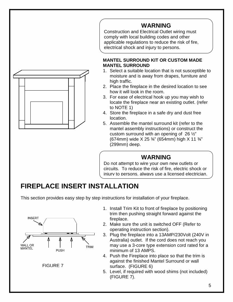
WARNING Construction and Electrical Outlet wiring must comply with local building codes and other applicable regulations to reduce the risk of fire, electrical shock and injury to persons.
WARNING Do not attempt to wire your own new outlets or circuits. To reduce the risk of fire, electric shock or injury to persons, always use a licensed electrician.
MANTEL SURROUND KIT OR CUSTOM MADE MANTEL SURROUND 1. Select a suitable location that is not susceptible to
moisture and is away from drapes, furniture and high traffic.
2. Place the fireplace in the desired location to see how it will look in the room.
3. For ease of electrical hook up you may wish to locate the fireplace near an existing outlet. (refer to NOTE 1)
4. Store the fireplace in a safe dry and dust free location.
5. Assemble the mantel surround kit (refer to the mantel assembly instructions) or construct the custom surround with an opening of 26 ½” (674mm) wide X 25 ¾” (654mm) high X 11 ¾” (299mm) deep.
FIREPLACE INSERT INSTALLATION
This section provides easy step by step instructions for installation of your fireplace.
1. Install Trim Kit to front of fireplace by positioning trim then pushing straight forward against the fireplace.
2. Make sure the unit is switched OFF (Refer to operating instruction section).
3. Plug the fireplace into a 13AMP/230Volt (240V in Australia) outlet. If the cord does not reach you may use a 3-core type extension cord rated for a minimum of 13 AMPS.
4. Push the Fireplace into place so that the trim is against the finished Mantel Surround or wall surface. (FIGURE 6)
5. Level, if required with wood shims (not included) (FIGURE 7).
FIGURE 7
5

OPERATION This section will explain the function of each convenient control.
1. To access the controls, open the upper grill by pulling, near the top right hand side, forward and down. (FIGURE 9)
2. To locate controls refer to FIGURE 10.
WARNING Ensure the power cord is not installed so that it is pinched or against a sharp edge and ensure that
the power cord is stored or secured to avoid tripping or snagging to reduce the risk of fire,
electric shock or injury to persons.
FIGURE 8
WARNING The centre and left hand side of the grille will get hot when the heater is operating. Take care to always grasp the grille on the right hand side.
FIGURE 9
6

B
A. MAIN ON/OFF SWITCH The ON/OFF SWITCH supplies power to all fireplace functions (Heater/Flame).
B. MAIN POWER INDICATOR LIGHT The main power indicator light will illuminate, confirming the unit is turned ON. C. FLAME ACTION CONTROL Turn the flame action control knob to adjust the flame speed to the desired level. D. FLAME BRIGHTNESS CONTROL Turn the flame brightness control knob to increase or decrease the brightness of the flame and embers. E. LED INDICATORS Indicates the current function of the fireplace F. MANUAL SELECTION BUTTONS To choose between flame effect setting, flame effect with low heat setting, and flame effect with high heat setting. G. HEATER THERMOSTAT CONTROL To adjust the temperature to your individual requirements, turn the thermostat control clockwise all the way to turn on the heater. When the room reached the desired temperature, turn the thermostat knob counter clockwise until you hear a click. Leave in this position to maintain the room temperature at this setting. For additional heat, turn clockwise until you hear the click again and the heater will turn on.
NOTE: The heater may emit a slight, harmless odor when first used. This odor is a normal condition caused by initial heating of internal heater parts and will not occur again.
3. To conceal the controls during the operation, return the grill to its original upright position.
G
E
DC
A
F
7

REMOTE CONTROL USAGE The fireplace is supplied with a radio frequency remote control. This remote control has a range of approximately 25 feet. (7.5m), it does not have to be pointed at the fireplace and can pass through most obstacles (including walls).
Remote Control Initialization This procedure is may be required if there is a loss of power to the remote control in the fireplace. (i.e. power failure, breaker tripped, main power switch is turned off) or if a new remote is used. 1. Ensure that power is supplied through main service panel. 2. Locate manual controls (refer to page 7). 3. Activate main power switch, red indicator light on the main power switch will illuminate. 4. Press — (on) button located on the remote control Manual Selection Control for 3 seconds (FIGURE 12). All 3 indicators will flash. Press the ON button on the transmitter (FIGURE 11). The indicators will flash rapidly and then turn off. This will synchronize the remote control transmitter and receiver
Remote Control Usage
The remote control operates the fireplace levels sequentially. The level is increased every time the ON button on the transmitter is pressed. The fireplace can be turned off at any point by pressing the OFF button on the remote control transmitter.
Level 1: The flame effect is turned on and the first red indicator light illuminates. Level 2: The flame effect remains on, the heater is activated to the low heat setting, and the first and second red indicator lights illuminate. Level 3: The flame effect remains on, the heater is set to the high heat setting, and all three red indicators illuminate.
MANUAL SELECTION SWITCH Operates fireplace in the same matter as the remote control transmitter. Pressing the — button has the same effect as the ON button on the remote control, and the O button has the same effect as the OFF button of the remote control. Pressing — once activates Level 1, twice activates Level 2, three times activates Level 3. Pressing O button turns the fireplace off.
Level 1 Indicator
Level 2 Indicator
Level 3 Indicator
FIGURE 11
8
Manual selectionbuttons
FIGURE 12
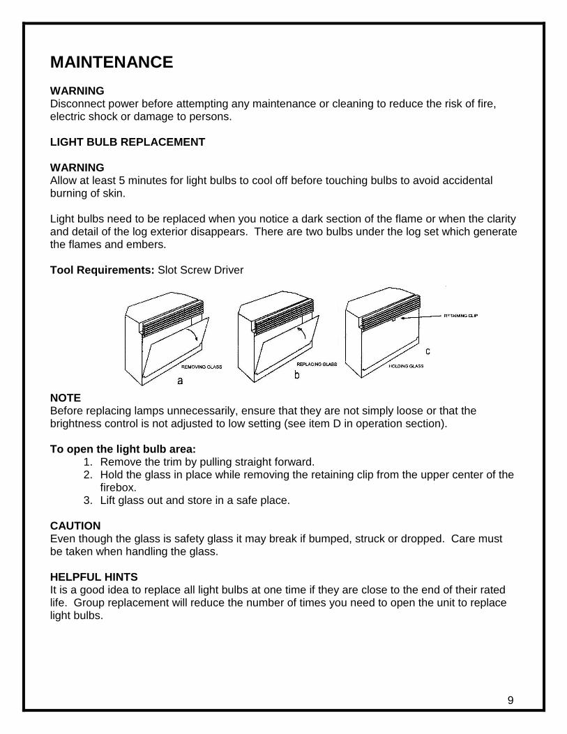
MAINTENANCE WARNING Disconnect power before attempting any maintenance or cleaning to reduce the risk of fire, electric shock or damage to persons. LIGHT BULB REPLACEMENT WARNING Allow at least 5 minutes for light bulbs to cool off before touching bulbs to avoid accidental burning of skin. Light bulbs need to be replaced when you notice a dark section of the flame or when the clarity and detail of the log exterior disappears. There are two bulbs under the log set which generate the flames and embers. Tool Requirements: Slot Screw Driver
NOTE Before replacing lamps unnecessarily, ensure that they are not simply loose or that the brightness control is not adjusted to low setting (see item D in operation section). To open the light bulb area:
1. Remove the trim by pulling straight forward. 2. Hold the glass in place while removing the retaining clip from the upper center of the
firebox. 3. Lift glass out and store in a safe place.
CAUTION Even though the glass is safety glass it may break if bumped, struck or dropped. Care must be taken when handling the glass. HELPFUL HINTS It is a good idea to replace all light bulbs at one time if they are close to the end of their rated life. Group replacement will reduce the number of times you need to open the unit to replace light bulbs.
9

To replace the bottom light bulbs: 1. lift up the front edge of the log until it clears the front tabs. Pull out until the rear tab
clears the back ledge, then lift out. 2. Examine the bulbs to determine which bulbs require replacement. 3. Hold the socket while unscrewing the bulb 4. Hold the socket while screwing in the new bulb. 5. Replace the log by pushing it down and in until it rests against the mirror.
LOWER LIGHT BULB REQUIREMENTS
Quantity of 4 clear chandelier or candelabra bulbs with an E-14 (small) socket base, 60 watt rating.
CAUTION Do not exceed 60 watts per lamp.
To replace the top light bulbs: 1. Locate the two upper bulbs inside the firebox at the top. 2. Examine the bulbs to determine which bulbs require replacement. 3. Hold the socket while unscrewing the bulb 4. Hold the socket while screwing in the new bulb.
UPPER LIGHT BULB REQUIREMENTS
Quantity of 2 clear chandelier or candelabra bulbs with an E-14 (small) socket base, 25 watt rating. Please refer to the label adjacent to the upper lamps for the correct wattage for your model.
CAUTION Do not exceed 25 watts per lamp.
To reassemble lamp area 1. Replace the glass and hold it in place at the top. 2. Fasten retaining clip to hold glass in place.
10
HELPFUL HINTS It is a good idea to replace all light bulbs at one time if they are close to the end of their rated life. Group replacement will reduce the number of times you need to open the unit to replace light bulbs. GLASS CLEANING The glass is cleaned in the factory during the assembly operation. During shipment, installation, handling, etc., the clear door may collect dust particles; these can be removed by dusting lightly with a clean dry cloth.
To remove fingerprints or other marks, the clear door can be cleaned with a damp cloth. The clear door should be completely dried with a lint free cloth to prevent water spots. CAUTION Do not use abrasive cleaners on glass surface or spray liquids directly onto any surface. FIREPLACE SURFACE CLEANING Use a cloth dampened with warm water only to clean painted surfaces of the electric fireplace. Do not use abrasive cleaners. 11

WARRANTY
Dimplex Electric Fireplaces are tested and inspected prior to shipment and are guaranteed from defect to the purchaser of each new product. Any part which proves to be defective in material or workmanship under normal use within one year will be repaired or replaced without charge.* The Company will not be responsible for any expense incurred for installation, removal for service, or transportation costs. Any such defect should be brought to the attention of the Dealer where the product was purchased and is authorized to repair or replace within the terms of this warranty. The Company’s only obligation under this warranty will be at its sole option to repair or replace any part proving defective or to refund the purchase price thereof.
The owner/user assumes all other risks, if any, including the risk of any direct, indirect or consequential loss or damage arising out of the use of or inability to use the product. The warranty will not apply if, in the sole judgment of the Company, damage or failure has resulted from accident, alteration, misuse, abuse, incorrect installation, or operation on an incorrect power source. The foregoing is in lieu of all other warranties expressed, implied, or statutory, and the Company neither assumes, nor authorizes any person to assume for it any other obligation, or liability in connection with said product.
*Light bulbs are not covered in the warranty.
SERVICE Contact your local dealer for service or warranty information.
The product complies with the European Safety Standard EN60335-2-30 and the European Standard for Electromagnetic Compatibility (EMC) EN55014, EN6055-2 and EN60555-3 which cover the essential requirements of EEG Directives 73/23 and 89/336.
12 Printed in China