Dimplex Fireplace Service Manual: DF2305-DF2307SS-DFB4047 ...
11
Service Manual 23” Compact Fireplace Model Number: DF2305 DF2307SS DFB4047 DFB2306 DFS2308 UL Part Number 6901740000 7400080000R03 In keeping with our policy of continuous product development, we reserve the right to make changes without notice. © 2011 Dimplex North America Limited Dimplex North America Limited 1367 Industrial Road Cambridge ON Canada N1R 7G8 1-888-346-7539 www.dimplex.com REV PCN DATE 02 - 5-DEC-11 03 28-JUN-13 IMPORTANT SAFETY INFORMATION: Always read this manual first before attempting to service this fireplace. For your safety, always comply with all warnings and safety instructions contained in this manual to prevent personal injury or property damage. DF2305 & DF2307SS DFB4047 DFB2306 & DFS2308
Transcript of Dimplex Fireplace Service Manual: DF2305-DF2307SS-DFB4047 ...
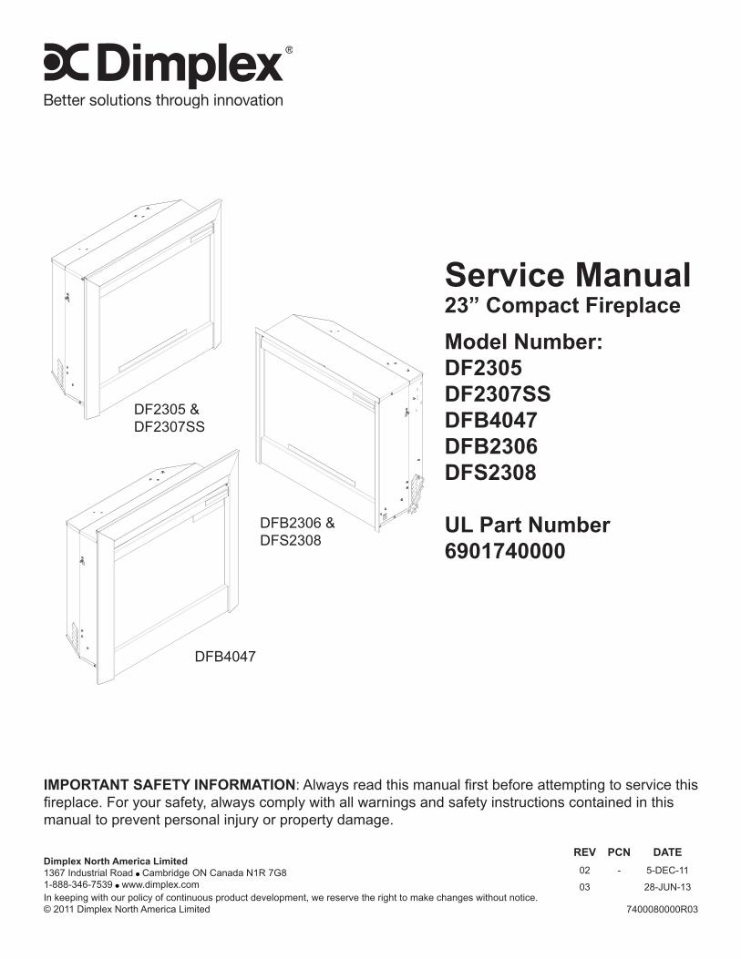
Service Manual23” Compact FireplaceModel Number:DF2305DF2307SSDFB4047DFB2306DFS2308
UL Part Number6901740000
7400080000R03In keeping with our policy of continuous product development, we reserve the right to make changes without notice.© 2011 Dimplex North America Limited
Dimplex North America Limited1367 Industrial Road Cambridge ON Canada N1R 7G81-888-346-7539 www.dimplex.com
REV PCN DATE02 - 5-DEC-11
03 28-JUN-13
IMPORTANT SAFETY INFORMATION: Always read this manual first before attempting to service this fireplace. For your safety, always comply with all warnings and safety instructions contained in this manual to prevent personal injury or property damage.
DF2305 & DF2307SS
DFB4047
DFB2306 & DFS2308
Mark
Text Box
"Click" on the replacement part number to view price and availability. www.morelectricheating.com
2 www.dimplex.com
Always use a qualified technician or service agency to repair this fireplace.
! NOTE: Procedures and techniques that are considered important enough to emphasize.
CAUTION: Procedures and techniques which, if not carefully followed, will result in damage to the equipment.
WARNING: Procedures and techniques which, if not carefully followed, will expose the user to the risk of fire, serious injury, or death.
Operation . . . . . . . . . . . . . . . . . . . . . . . . . . . . . . . . . . . . . . . . . . . . . . . . . . . . . . . . . . . . 3Maintenance . . . . . . . . . . . . . . . . . . . . . . . . . . . . . . . . . . . . . . . . . . . . . . . . . . . . . . . . . 4Exploded Parts Diagram . . . . . . . . . . . . . . . . . . . . . . . . . . . . . . . . . . . . . . . . . . . . . . . . 5Replacement Parts . . . . . . . . . . . . . . . . . . . . . . . . . . . . . . . . . . . . . . . . . . . . . . . . . . . . 5Wiring Diagram . . . . . . . . . . . . . . . . . . . . . . . . . . . . . . . . . . . . . . . . . . . . . . . . . . . . . . . 6Light Harness Replacement . . . . . . . . . . . . . . . . . . . . . . . . . . . . . . . . . . . . . . . . . . . . . 73-Position Switch or Heater Switch Replacement . . . . . . . . . . . . . . . . . . . . . . . . . . . . . 7Thermostat Replacement . . . . . . . . . . . . . . . . . . . . . . . . . . . . . . . . . . . . . . . . . . . . . . . 7Flicker Rod/Motor Replacement . . . . . . . . . . . . . . . . . . . . . . . . . . . . . . . . . . . . . . . . . . 8Heater Assembly Replacement . . . . . . . . . . . . . . . . . . . . . . . . . . . . . . . . . . . . . . . . . . . 8Remote Control Receiver Replacement . . . . . . . . . . . . . . . . . . . . . . . . . . . . . . . . . . . . 8Power Cord Replacement . . . . . . . . . . . . . . . . . . . . . . . . . . . . . . . . . . . . . . . . . . . . . . . 8Capacitor and Terminal Block Replacement . . . . . . . . . . . . . . . . . . . . . . . . . . . . . . . . . 9Troubleshooting Guide . . . . . . . . . . . . . . . . . . . . . . . . . . . . . . . . . . . . . . . . . . . . . . . . 10
TABLE OF CONTENTS
3
Remote ControlThe fireplace is supplied with a radio frequency remote control. This remote control has a range of approximately 50 feet (15.25 m), it does not have to be pointed at the fireplace and can pass through most obstacles (including walls). It is supplied with one of hundreds of independent frequencies to prevent interference with other units.! NOTE: Before attempting any operation with the
remote, pull the plastic insulator strip out from between the remote casing and battery cover (Figure 2).
To operate, push the ON button to turn fireplace on, push the OFF button to turn the fireplace off.! NOTE: Ensure that the fireplace 3-Position switch is
set to the remote control setting.
Remote Control Initialization/ReprogrammingIf the hand held transmitter or receiver board has been replaced, follow these steps to initialize the transmitter and receiver:1. Place the 3-Position Switch (Figure 1A) in the OFF
(“O”) position.2. Wait a minimum of five (5) seconds and set the 3
Position Switch to the Remote position (“II”).3. Within 10 seconds of changing the switch position,
press the ON button located on the remote control (Figure 2).
This will synchronize the remote control and the remote control receiver.! NOTE: You will have only 10 seconds to perform this
last step. Failure to do so will result in these steps needing to be followed again.
Battery Replacement To replace the battery:1. Slide battery cover open on the remote control (Figure
2).2. Install one (1) 12-Volt (A23) battery in the battery
holder.3. Close the battery cover
Battery must be recycled or disposed of properly. Check with your Local Authority or Retailer for recycling advice in your area.
OPERATION
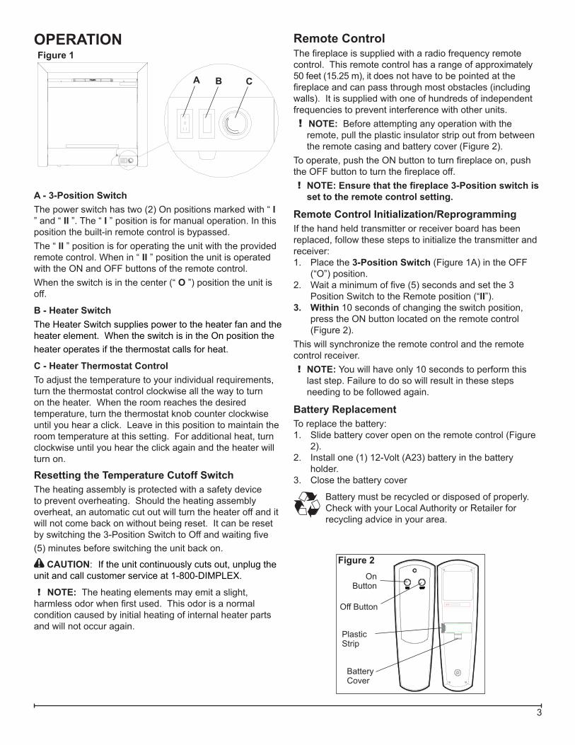
A - 3-Position Switch The power switch has two (2) On positions marked with “ I ” and “ II ”. The “ I ” position is for manual operation. In this position the built-in remote control is bypassed. The “ II ” position is for operating the unit with the provided remote control. When in “ II ” position the unit is operated with the ON and OFF buttons of the remote control.When the switch is in the center (“ O ”) position the unit is off.
B - Heater SwitchThe Heater Switch supplies power to the heater fan and the heater element. When the switch is in the On position the heater operates if the thermostat calls for heat.
C - Heater Thermostat ControlTo adjust the temperature to your individual requirements, turn the thermostat control clockwise all the way to turn on the heater. When the room reaches the desired temperature, turn the thermostat knob counter clockwise until you hear a click. Leave in this position to maintain the room temperature at this setting. For additional heat, turn clockwise until you hear the click again and the heater will turn on.
Resetting the Temperature Cutoff SwitchThe heating assembly is protected with a safety device to prevent overheating. Should the heating assembly overheat, an automatic cut out will turn the heater off and it will not come back on without being reset. It can be reset by switching the 3-Position Switch to Off and waiting five (5) minutes before switching the unit back on.
CAUTION: If the unit continuously cuts out, unplug the unit and call customer service at 1-800-DIMPLEX.
! NOTE: The heating elements may emit a slight, harmless odor when first used. This odor is a normal condition caused by initial heating of internal heater parts and will not occur again.
Figure 2
Off Button
On Button
Battery Cover
Plastic Strip
Figure 1
A B C
4 www.dimplex.com
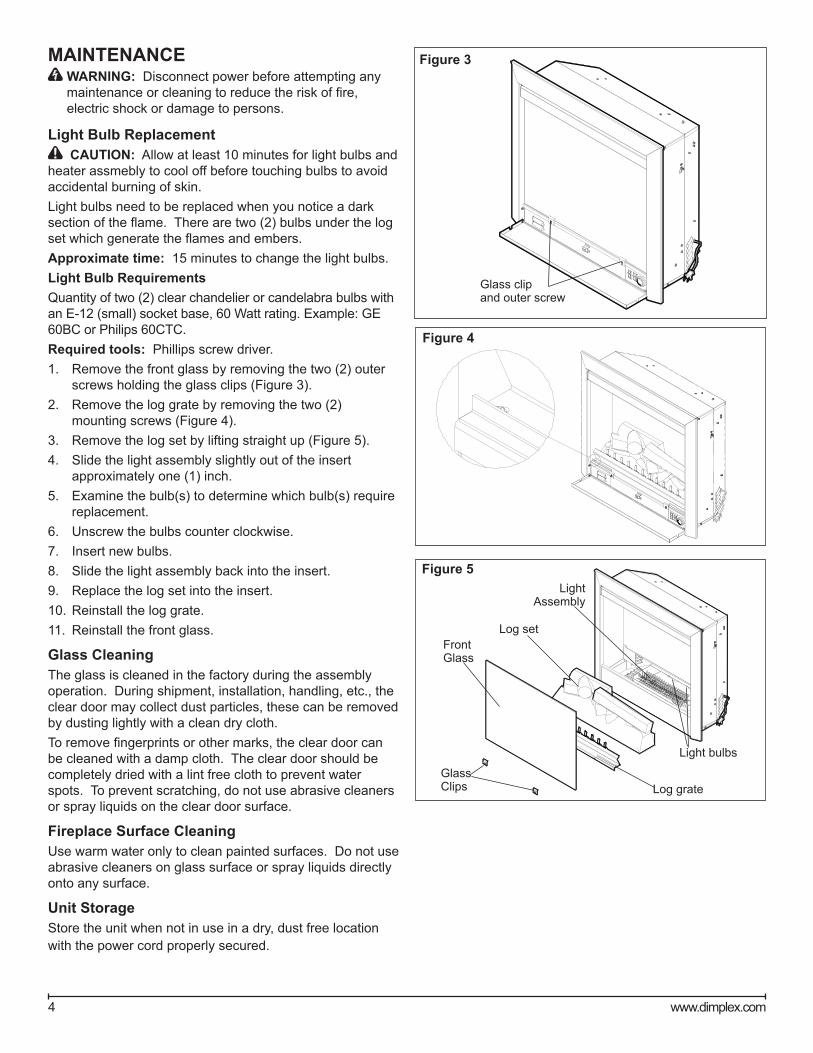
MAINTENANCE WARNING: Disconnect power before attempting any maintenance or cleaning to reduce the risk of fire, electric shock or damage to persons.
Light Bulb Replacement CAUTION: Allow at least 10 minutes for light bulbs and
heater assmebly to cool off before touching bulbs to avoid accidental burning of skin.Light bulbs need to be replaced when you notice a dark section of the flame. There are two (2) bulbs under the log set which generate the flames and embers.Approximate time: 15 minutes to change the light bulbs.Light Bulb RequirementsQuantity of two (2) clear chandelier or candelabra bulbs with an E-12 (small) socket base, 60 Watt rating. Example: GE 60BC or Philips 60CTC.Required tools: Phillips screw driver.1. Remove the front glass by removing the two (2) outer
screws holding the glass clips (Figure 3).2. Remove the log grate by removing the two (2)
mounting screws (Figure 4).3. Remove the log set by lifting straight up (Figure 5).4. Slide the light assembly slightly out of the insert
approximately one (1) inch. 5. Examine the bulb(s) to determine which bulb(s) require
replacement. 6. Unscrew the bulbs counter clockwise.7. Insert new bulbs.8. Slide the light assembly back into the insert.9. Replace the log set into the insert.10. Reinstall the log grate.11. Reinstall the front glass.
Glass CleaningThe glass is cleaned in the factory during the assembly operation. During shipment, installation, handling, etc., the clear door may collect dust particles, these can be removed by dusting lightly with a clean dry cloth.To remove fingerprints or other marks, the clear door can be cleaned with a damp cloth. The clear door should be completely dried with a lint free cloth to prevent water spots. To prevent scratching, do not use abrasive cleaners or spray liquids on the clear door surface.
Fireplace Surface CleaningUse warm water only to clean painted surfaces. Do not use abrasive cleaners on glass surface or spray liquids directly onto any surface.
Unit StorageStore the unit when not in use in a dry, dust free location with the power cord properly secured.
Figure 4
Figure 5
Log set
Light Assembly
Light bulbs
Log grate
FrontGlass
GlassClips
Figure 3
Glass clip and outer screw
5
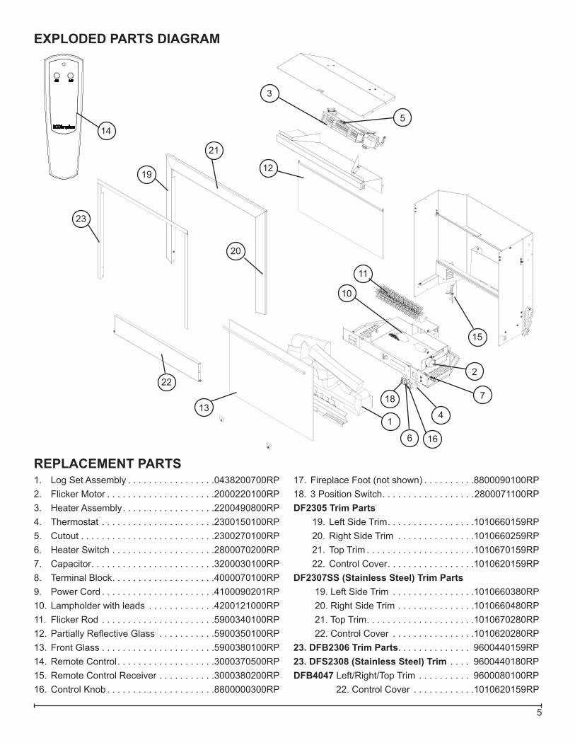
EXPLODED PARTS DIAGRAM
6
18
2
3
4
5
22
10
137
12
15
11
1
16
14
REPLACEMENT PARTS1. Log Set Assembly . . . . . . . . . . . . . . . . .0438200700RP2. Flicker Motor . . . . . . . . . . . . . . . . . . . . .2000220100RP3. Heater Assembly . . . . . . . . . . . . . . . . . .2200490800RP4. Thermostat . . . . . . . . . . . . . . . . . . . . . .2300150100RP5. Cutout . . . . . . . . . . . . . . . . . . . . . . . . . .2300270100RP6. Heater Switch . . . . . . . . . . . . . . . . . . . .2800070200RP7. Capacitor . . . . . . . . . . . . . . . . . . . . . . . .3200030100RP8. Terminal Block . . . . . . . . . . . . . . . . . . . .4000070100RP9. Power Cord . . . . . . . . . . . . . . . . . . . . . .4100090201RP10. Lampholder with leads . . . . . . . . . . . . .4200121000RP11. Flicker Rod . . . . . . . . . . . . . . . . . . . . . .5900340100RP12. Partially Reflective Glass . . . . . . . . . . .5900350100RP13. Front Glass . . . . . . . . . . . . . . . . . . . . . .5900380100RP14. Remote Control . . . . . . . . . . . . . . . . . . .3000370500RP15. Remote Control Receiver . . . . . . . . . . .3000380200RP16. Control Knob . . . . . . . . . . . . . . . . . . . . .8800000300RP
17. Fireplace Foot (not shown) . . . . . . . . . .8800090100RP18. 3 Position Switch . . . . . . . . . . . . . . . . . .2800071100RPDF2305 Trim Parts
19. Left Side Trim . . . . . . . . . . . . . . . . .1010660159RP20. Right Side Trim . . . . . . . . . . . . . . .1010660259RP21. Top Trim . . . . . . . . . . . . . . . . . . . . .1010670159RP22. Control Cover . . . . . . . . . . . . . . . . .1010620159RP
DF2307SS (Stainless Steel) Trim Parts19. Left Side Trim . . . . . . . . . . . . . . . .1010660380RP20. Right Side Trim . . . . . . . . . . . . . . .1010660480RP21. Top Trim . . . . . . . . . . . . . . . . . . . . .1010670280RP22. Control Cover . . . . . . . . . . . . . . . .1010620280RP
23. DFB2306 Trim Parts. . . . . . . . . . . . . . 9600440159RP23. DFS2308 (Stainless Steel) Trim . . . . 9600440180RPDFB4047 Left/Right/Top Trim . . . . . . . . . . 9600080100RP
22. Control Cover . . . . . . . . . . . .1010620159RP
20
21
19
23
Mark
Text Box
"Click" on the replacement part number to view price and availability. www.morelectricheating.com
6 www.dimplex.com
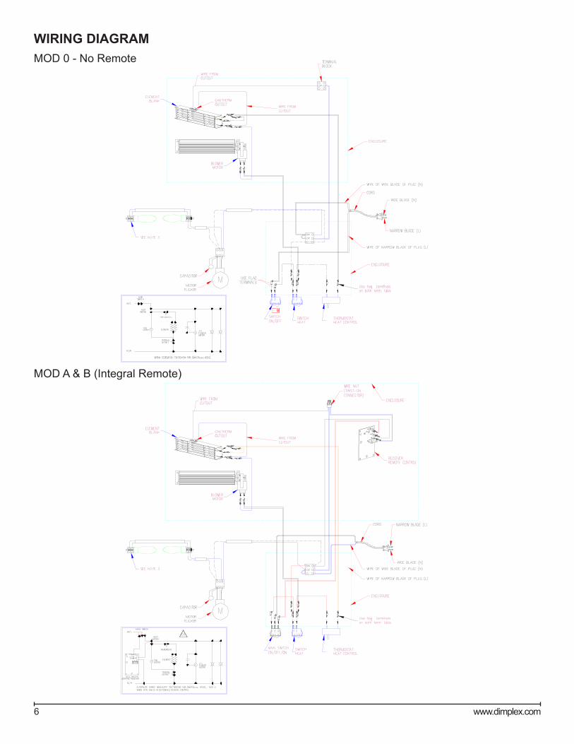
WIRING DIAGRAM
MOD A & B (Integral Remote)
MOD 0 - No Remote
7
LIGHT HARNESS REPLACEMENTTools Required: Phillips Head Screwdriver
CAUTION: If unit was operating prior to servicing allow at least 10 minutes for lights, heating elements and top panel to cool off to avoid accidental burning of skin.
WARNING: Disconnect power before attempting any maintenance to reduce the risk of electric shock or damage to persons.1. Open the front control cover.2. Remove front glass by removing the 2 outer screws
holding the glass clips. (Figure 3)3. Remove the log grate by removing the 4 mounting
screws. (Figure 4)4. Remove the log set by lifting straight up. 5. Slide the light assembly slightly out of the insert.6. Remove the light bulbs. Hold the socket while un-
screwing the old bulb.7. Remove the screws at the back holding the light sock-
ets to the assembly. (Figure 6)8. Pull the light sockets out towards the front of the unit.9. Disconnect the socket wires from the terminal block
noting the original locations.10. Install the new light sockets, securing them with the
removed screws at the back of the assembly.11. Reinstall the wires into the original locations.12. Hold the socket while screwing in the new bulb.13. Reassemble in the reverse order as above.
3-POSITION SWITCH OR HEATER SWITCH REPLACEMENTTools Required: Phillips Head Screwdriver
Flat Head Screwdriver CAUTION: If unit was operating prior to servicing allow
at least 10 minutes for lights, heating elements and top panel to cool off to avoid accidental burning of skin.
WARNING: Disconnect power before attempting any maintenance to reduce the risk of electric shock or damage to persons.1. Open the front control cover.
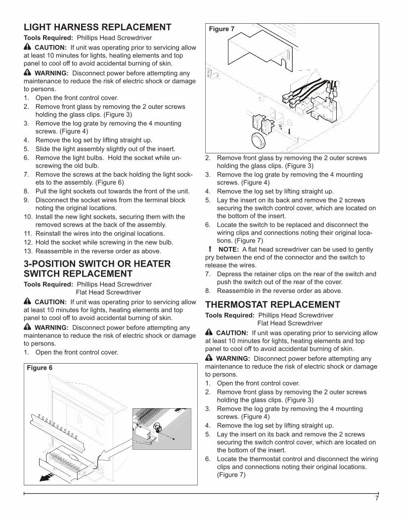
Figure 6
Figure 7
2. Remove front glass by removing the 2 outer screws holding the glass clips. (Figure 3)
3. Remove the log grate by removing the 4 mounting screws. (Figure 4)
4. Remove the log set by lifting straight up.5. Lay the insert on its back and remove the 2 screws
securing the switch control cover, which are located on the bottom of the insert.
6. Locate the switch to be replaced and disconnect the wiring clips and connections noting their original loca-tions. (Figure 7)
! NOTE: A flat head screwdriver can be used to gently pry between the end of the connector and the switch to release the wires.7. Depress the retainer clips on the rear of the switch and
push the switch out of the rear of the cover.8. Reassemble in the reverse order as above.
THERMOSTAT REPLACEMENTTools Required: Phillips Head Screwdriver
Flat Head Screwdriver CAUTION: If unit was operating prior to servicing allow
at least 10 minutes for lights, heating elements and top panel to cool off to avoid accidental burning of skin.
WARNING: Disconnect power before attempting any maintenance to reduce the risk of electric shock or damage to persons.1. Open the front control cover.2. Remove front glass by removing the 2 outer screws
holding the glass clips. (Figure 3)3. Remove the log grate by removing the 4 mounting
screws. (Figure 4)4. Remove the log set by lifting straight up.5. Lay the insert on its back and remove the 2 screws
securing the switch control cover, which are located on the bottom of the insert.
6. Locate the thermostat control and disconnect the wiring clips and connections noting their original locations. (Figure 7)
8 www.dimplex.com
! NOTE: A flat head screwdriver can be used to gently pry between the end of the connector and the switch to release the wires.7. Remove the thermostat control knob by pulling straight
out.8. Remove the 2 mounting screws and replace the old
thermostat with the new one.9. Reassemble in the reverse order as above.
FLICKER ROD/MOTOR REPLACEMENTTools Required: Phillips Head Screwdriver
Flat Head Screwdriver CAUTION: If unit was operating prior to servicing allow
at least 10 minutes for lights, heating elements and top panel to cool off to avoid accidental burning of skin.
WARNING: Disconnect power before attempting any maintenance to reduce the risk of electric shock or damage to persons.1. Open the front control cover.2. Remove front glass by removing the 2 outer screws
holding the glass clips. (Figure 3)3. Remove the log grate by removing the 4 mounting
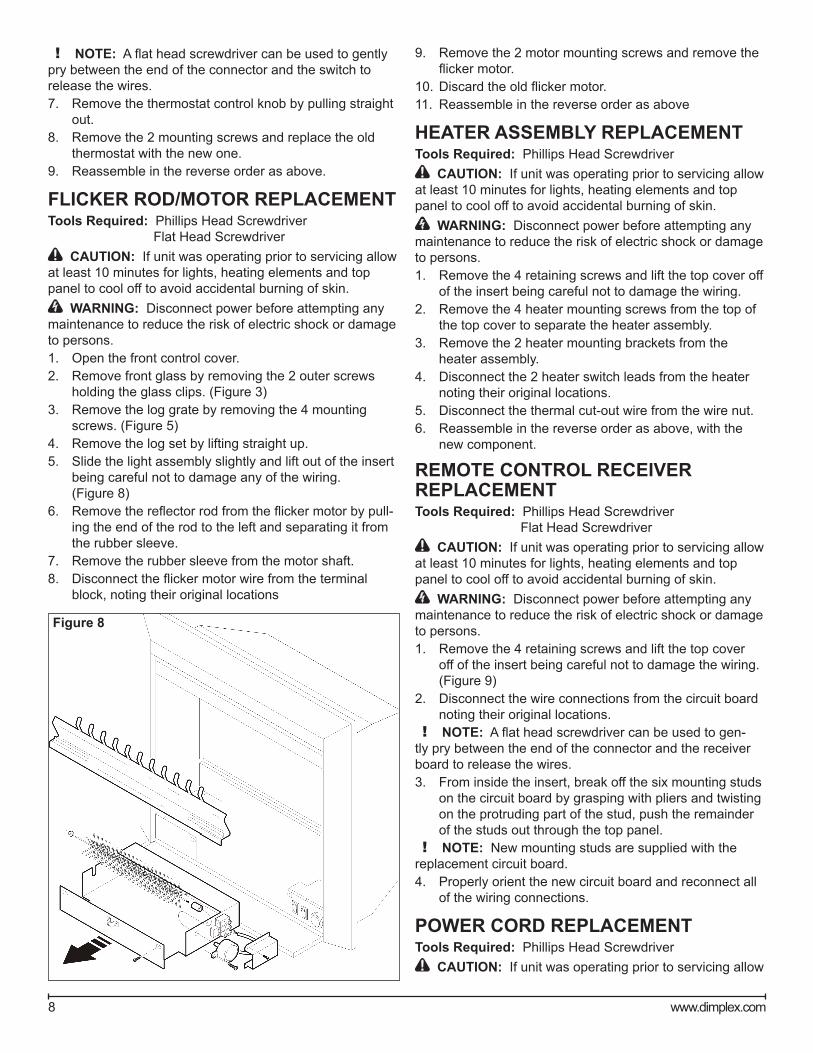
screws. (Figure 5)4. Remove the log set by lifting straight up. 5. Slide the light assembly slightly and lift out of the insert
being careful not to damage any of the wiring. (Figure 8)
6. Remove the reflector rod from the flicker motor by pull-ing the end of the rod to the left and separating it from the rubber sleeve.
7. Remove the rubber sleeve from the motor shaft.8. Disconnect the flicker motor wire from the terminal
block, noting their original locations
9. Remove the 2 motor mounting screws and remove the flicker motor.
10. Discard the old flicker motor.11. Reassemble in the reverse order as above
HEATER ASSEMBLY REPLACEMENTTools Required: Phillips Head Screwdriver
CAUTION: If unit was operating prior to servicing allow at least 10 minutes for lights, heating elements and top panel to cool off to avoid accidental burning of skin.
WARNING: Disconnect power before attempting any maintenance to reduce the risk of electric shock or damage to persons.1. Remove the 4 retaining screws and lift the top cover off
of the insert being careful not to damage the wiring. 2. Remove the 4 heater mounting screws from the top of
the top cover to separate the heater assembly.3. Remove the 2 heater mounting brackets from the
heater assembly.4. Disconnect the 2 heater switch leads from the heater
noting their original locations.5. Disconnect the thermal cut-out wire from the wire nut.6. Reassemble in the reverse order as above, with the
new component.
REMOTE CONTROL RECEIVER REPLACEMENTTools Required: Phillips Head Screwdriver
Flat Head Screwdriver CAUTION: If unit was operating prior to servicing allow
at least 10 minutes for lights, heating elements and top panel to cool off to avoid accidental burning of skin.
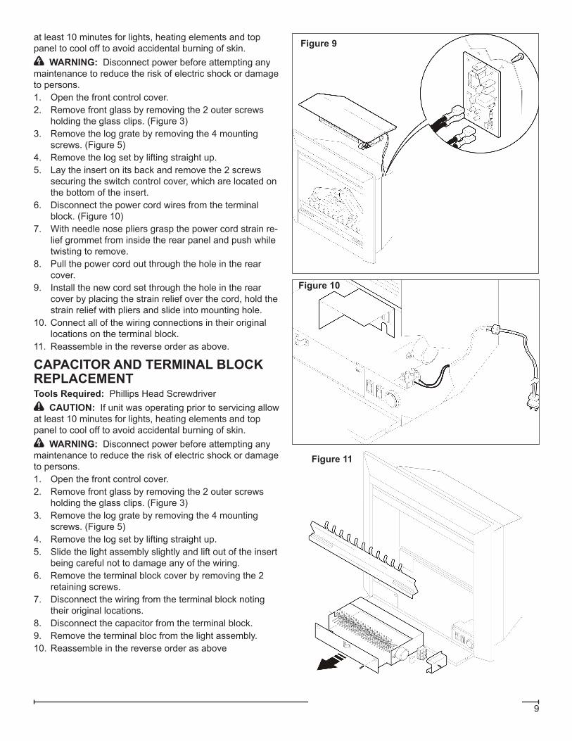
WARNING: Disconnect power before attempting any maintenance to reduce the risk of electric shock or damage to persons.1. Remove the 4 retaining screws and lift the top cover
off of the insert being careful not to damage the wiring. (Figure 9)
2. Disconnect the wire connections from the circuit board noting their original locations.
! NOTE: A flat head screwdriver can be used to gen-tly pry between the end of the connector and the receiver board to release the wires.3. From inside the insert, break off the six mounting studs
on the circuit board by grasping with pliers and twisting on the protruding part of the stud, push the remainder of the studs out through the top panel.
! NOTE: New mounting studs are supplied with the replacement circuit board.4. Properly orient the new circuit board and reconnect all
of the wiring connections.
POWER CORD REPLACEMENTTools Required: Phillips Head Screwdriver
CAUTION: If unit was operating prior to servicing allow
Figure 8
9
at least 10 minutes for lights, heating elements and top panel to cool off to avoid accidental burning of skin.
WARNING: Disconnect power before attempting any maintenance to reduce the risk of electric shock or damage to persons.1. Open the front control cover.2. Remove front glass by removing the 2 outer screws
holding the glass clips. (Figure 3)3. Remove the log grate by removing the 4 mounting
screws. (Figure 5)4. Remove the log set by lifting straight up.5. Lay the insert on its back and remove the 2 screws
securing the switch control cover, which are located on the bottom of the insert.
6. Disconnect the power cord wires from the terminal block. (Figure 10)
7. With needle nose pliers grasp the power cord strain re-lief grommet from inside the rear panel and push while twisting to remove.
8. Pull the power cord out through the hole in the rear cover.
9. Install the new cord set through the hole in the rear cover by placing the strain relief over the cord, hold the strain relief with pliers and slide into mounting hole.
10. Connect all of the wiring connections in their original locations on the terminal block.
11. Reassemble in the reverse order as above.
CAPACITOR AND TERMINAL BLOCK REPLACEMENTTools Required: Phillips Head Screwdriver
CAUTION: If unit was operating prior to servicing allow at least 10 minutes for lights, heating elements and top panel to cool off to avoid accidental burning of skin.
WARNING: Disconnect power before attempting any maintenance to reduce the risk of electric shock or damage to persons.1. Open the front control cover.2. Remove front glass by removing the 2 outer screws
holding the glass clips. (Figure 3)3. Remove the log grate by removing the 4 mounting
screws. (Figure 5)4. Remove the log set by lifting straight up. 5. Slide the light assembly slightly and lift out of the insert
being careful not to damage any of the wiring.6. Remove the terminal block cover by removing the 2
retaining screws.7. Disconnect the wiring from the terminal block noting
their original locations.8. Disconnect the capacitor from the terminal block.9. Remove the terminal bloc from the light assembly.10. Reassemble in the reverse order as above
Figure 9
Figure 10
Figure 11

10 www.dimplex.com
PROBLEM CAUSE SOLUTIONGeneralCircuit breaker trips or fuse blows when unit is turned on
Short in unit wiring. Trace wiring in unit.Improper circuit current rating Additional appliances may exceed the current rating
of the circuit breaker or fuse. Plug unit into another outlet or install unit on a dedicated 15 amp circuit.
Unit turns on or off by itself Remote Control has a similar frequency to other remotes in the area.
Replace Remote Control. Initialize to Remote Control Receiver
Radio frequency disturbance from out-side sources.
Replace Remote Control and Remote Control Re-ceiver where necessary. Initialize to Remote Control and Receiver
Defective Remote Control Receiver Replace Remote Control Receiver. Initialize to Re-mote Control and Receiver
Lights dim in room while the unit is on
Unit is drawing close to circuit current rating
Move the unit to another outlet or install unit on a dedi-cated 15 amp circuit
Power cord gets warm Normal operation The power cord may get slightly warm to the touch when the heater is on
Defective power cord Replace power cord if cord gets hot to the touch.AppearanceFireplace does not turn on Manu-ally
Improper operation Refer to Operation SectionNo incoming power from the electrical wall socket
Check fuse/breaker panel
Defective 3-Position switch Replace 3-Position switchDefective Remote Control Receiver Replace Remote Control Receiver. Initialize to Remote
Control and Receiver.Fireplace does not turn on with the Remote Control
Improper operation Refer to Operation SectionRemote Control not initialized to fireplace Initialize the Remote ControlRemote Control not working Install new battery into the Remote Control. Initalize
remote control, if necessaryReplace remote control receiver or remote control where necessary. Initialize to Remote Control Re-ceiver
Loose wiring Check wiring connectionsFlame Frozen Defective Flicker Motor Replace Flicker Motor
Loose wiring Check wiring connectionsFlame not bright or flame not visible
Burnt out light bulbs Replace light bulbsLoose wiring Check wiring connectionsDefective Light Harness Replace Light Harness
Log set dim, not glowing Burnt out light bulbs Replace light bulbsFlame Shutter Defective Flicker Motor Replace Flicker MotorLight leaking around the log set Log set not positioned properly Check log set for proper fit
TROUBLESHOOTING GUIDE
11
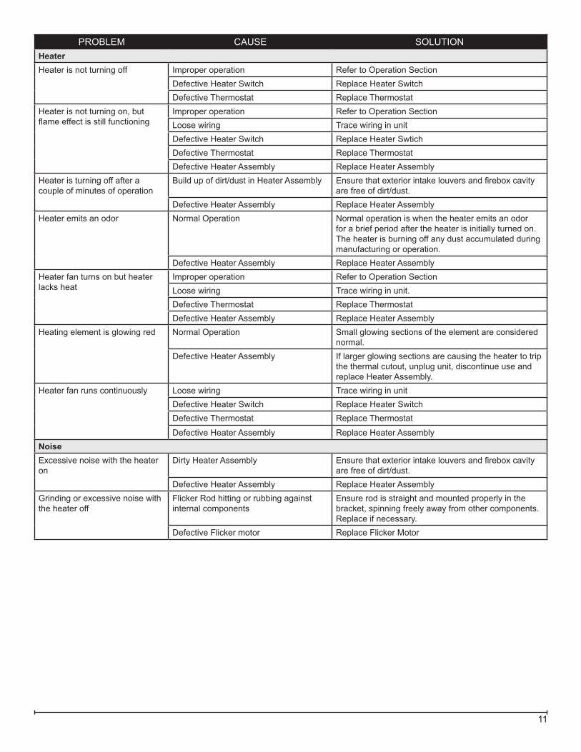
PROBLEM CAUSE SOLUTIONHeaterHeater is not turning off Improper operation Refer to Operation Section
Defective Heater Switch Replace Heater SwitchDefective Thermostat Replace Thermostat
Heater is not turning on, but flame effect is still functioning
Improper operation Refer to Operation SectionLoose wiring Trace wiring in unitDefective Heater Switch Replace Heater SwtichDefective Thermostat Replace ThermostatDefective Heater Assembly Replace Heater Assembly
Heater is turning off after a couple of minutes of operation
Build up of dirt/dust in Heater Assembly Ensure that exterior intake louvers and firebox cavity are free of dirt/dust.
Defective Heater Assembly Replace Heater AssemblyHeater emits an odor Normal Operation Normal operation is when the heater emits an odor
for a brief period after the heater is initially turned on. The heater is burning off any dust accumulated during manufacturing or operation.
Defective Heater Assembly Replace Heater AssemblyHeater fan turns on but heater lacks heat
Improper operation Refer to Operation SectionLoose wiring Trace wiring in unit.Defective Thermostat Replace ThermostatDefective Heater Assembly Replace Heater Assembly
Heating element is glowing red Normal Operation Small glowing sections of the element are considered normal.
Defective Heater Assembly If larger glowing sections are causing the heater to trip the thermal cutout, unplug unit, discontinue use and replace Heater Assembly.
Heater fan runs continuously Loose wiring Trace wiring in unitDefective Heater Switch Replace Heater SwitchDefective Thermostat Replace Thermostat
Defective Heater Assembly Replace Heater AssemblyNoiseExcessive noise with the heater on
Dirty Heater Assembly Ensure that exterior intake louvers and firebox cavity are free of dirt/dust.
Defective Heater Assembly Replace Heater AssemblyGrinding or excessive noise with the heater off
Flicker Rod hitting or rubbing against internal components
Ensure rod is straight and mounted properly in the bracket, spinning freely away from other components. Replace if necessary.
Defective Flicker motor Replace Flicker Motor