Power Management PML630/Compact Load-Shedding Solution … · Relion® 630 series Power Management...
96
Relion ® 630 series Power Management PML630/Compact Load-Shedding Solution IEC 61850 Communication Protocol Manual
Transcript of Power Management PML630/Compact Load-Shedding Solution … · Relion® 630 series Power Management...
Relion® 630 series
Power ManagementPML630/Compact Load-Shedding SolutionIEC 61850 Communication Protocol Manual

Document ID: 1MRS757260Issued: 2013-10-14
Revision: DProduct version: 1.2
© Copyright 2013 ABB. All rights reserved

CopyrightThis document and parts thereof must not be reproduced or copied without writtenpermission from ABB, and the contents thereof must not be imparted to a thirdparty, nor used for any unauthorized purpose.
The software or hardware described in this document is furnished under a licenseand may be used, copied, or disclosed only in accordance with the terms of suchlicense.
TrademarksABB and Relion are registered trademarks of the ABB Group. All other brand orproduct names mentioned in this document may be trademarks or registeredtrademarks of their respective holders.
WarrantyPlease inquire about the terms of warranty from your nearest ABB representative.
http://www.abb.com/substationautomation

DisclaimerThe data, examples and diagrams in this manual are included solely for the conceptor product description and are not to be deemed as a statement of guaranteedproperties. All persons responsible for applying the equipment addressed in thismanual must satisfy themselves that each intended application is suitable andacceptable, including that any applicable safety or other operational requirementsare complied with. In particular, any risks in applications where a system failure and/or product failure would create a risk for harm to property or persons (including butnot limited to personal injuries or death) shall be the sole responsibility of theperson or entity applying the equipment, and those so responsible are herebyrequested to ensure that all measures are taken to exclude or mitigate such risks.
This product has been designed to be connected and communicate data andinformation via a network interface which should be connected to a securenetwork. It is the sole responsibility of the person or entity responsible for networkadministration to ensure a secure connection to the network and to take thenecessary measures (such as, but not limited to, installation of firewalls, applicationof authentication measures, encryption of data, installation of anti virus programs,etc.) to protect the product and the network, its system and interface included,against any kind of security breaches, unauthorized access, interference, intrusion,leakage and/or theft of data or information. ABB is not liable for any such damagesand/or losses.
This document has been carefully checked by ABB but deviations cannot becompletely ruled out. In case any errors are detected, the reader is kindly requestedto notify the manufacturer. Other than under explicit contractual commitments, inno event shall ABB be responsible or liable for any loss or damage resulting fromthe use of this manual or the application of the equipment.

ConformityThis product complies with the directive of the Council of the EuropeanCommunities on the approximation of the laws of the Member States relating toelectromagnetic compatibility (EMC Directive 2004/108/EC) and concerningelectrical equipment for use within specified voltage limits (Low-voltage directive2006/95/EC). This conformity is the result of tests conducted by ABB inaccordance with the product standards EN 50263 and EN 60255-26 for the EMCdirective, and with the product standards EN 60255-1 and EN 60255-27 for the lowvoltage directive. The product is designed in accordance with the internationalstandards of the IEC 60255 series.

Table of contents
Section 1 Introduction.......................................................................3This manual........................................................................................3Intended audience..............................................................................3Product documentation.......................................................................3
Product documentation set............................................................3Document revision history.............................................................4Related documentation..................................................................5
Symbols and conventions...................................................................5Symbols.........................................................................................5Document conventions..................................................................5Functions, codes and symbols......................................................6
Section 2 Introduction to IEC 61850.................................................9Related documentation to IEC 61850..........................................10
Section 3 Substation Configuration description Language(SCL)..............................................................................13The substation section......................................................................14The communication section..............................................................14The IED section................................................................................15Tool concept.....................................................................................17
IEC 61850 engineering with PCM600 and IET600......................18Engineering concept in IEC 61850-6................................................18
Section 4 Communication profile....................................................21
Section 5 Supported services.........................................................23
Section 6 Data sets and control blocks..........................................25Data sets..........................................................................................25Report control block (URCB/BRCB).................................................26GOOSE Control Blocks (GoCB).......................................................30
Section 7 Logical node data model................................................33Common data objects in each logical node......................................33Logical nodes for control..................................................................34
IEC61850 generic communication I/O functions DPGGIO..........34Logical node for monitoring..............................................................35
Station battery supervision SPVNZBAT......................................35IEC61850 generic communication I/O functions MVGGIO..........36IEC61850 generic communication I/O functions SPGGIO..........37
Table of contents
PML630/Compact Load-Shedding Solution 1Communication Protocol Manual
Multipurpose analogue protection function MAPGAPC...............38Event counter CNTGGIO.............................................................39
Logical node for power management...............................................40Input interface function for power source data PSCWI ...............40Input interface function for sheddable load data LDMMXU ........46Input interface function for network circuit breaker dataNCBDCSWI.................................................................................59Input interface function for network power data NPMMXU..........61Contingency based fast load-shed function LSCACLS...............62Sheddable load trip command LSPTRC .....................................73Output interface function for sub network data SNWRCLS.........78Output interface function for peer network dataPPLSGGIO..................................................................................82
Logical node for disturbance recorder function................................84Disturbance report DRRDRE.......................................................84
Load-shedding power management function blocks........................86
Section 8 Glossary.........................................................................87
Table of contents
2 PML630/Compact Load-Shedding SolutionCommunication Protocol Manual

Section 1 Introduction
1.1 This manual
The communication protocol manual describes a communication protocolsupported by the IED. The manual concentrates on vendor-specific implementations.
1.2 Intended audience
This manual addresses the communication system engineer or system integratorresponsible for pre-engineering and engineering for communication setup in asubstation from an IED perspective.
The system engineer or system integrator must have a basic knowledge ofcommunication in protection and control systems and thorough knowledge of thespecific communication protocol.
1.3 Product documentation
1.3.1 Product documentation setThe application engineering guide provides information for the completeconfiguration of the load-shedding application comprising Relion® IEDs, RIO600,load-shedding controller IED and COM600 using PCM600, IET600 and SAB600.With a practical example, the document explains all the steps from system planningand engineering to application functionality and IED parameterization for realizingthe load-shedding functionality using the IEDs.
The commissioning manual contains instructions on how to commission the IEDwith the load-shedding power management functions. The manual can also be usedby system engineers and maintenance personnel for assistance during the testingphase. The manual provides procedures for checking external circuitry andenergizing the IED, parameter setting and configuration. The manual describes theprocess of testing an IED in a substation that is not in service. The chapters areorganized in chronological order in which the IED should be commissioned.
The communication protocol manual describes a communication protocolsupported by the IED. The manual concentrates on vendor-specific implementations.
1MRS757260 D Section 1Introduction
PML630/Compact Load-Shedding Solution 3Communication Protocol Manual

The engineering manual contains instructions to engineer the IEDs for the load-shedding power management functionality using PCM600. The manual providesinstructions on how to set up a PCM600 project and insert IEDs to the projectstructure and also recommends a sequence for engineering of the IEDs' LHMIfunctions and IEC 61850 communication engineering.
The installation manual contains instructions on how to install the IED. Themanual provides procedures for mechanical and electrical installation. The chaptersare organized in chronological order in which the IED should be installed.
The operation manual contains instructions on how to operate the IED once it hasbeen commissioned. The manual provides instructions for monitoring, controllingand setting the IED.
The point list manual describes the outlook and properties of the data pointsspecific to the IED. The manual should be used in conjunction with thecorresponding communication protocol manual.
The technical manual contains application and functionality descriptions and listsfunction blocks, logic diagrams, input and output signals, setting parameters andtechnical data sorted per function. The manual can be used as a technical referenceduring the engineering phase, installation and commissioning phase, and duringnormal service.
See the 630 series documentation for installation andcommissioning manuals. The PML630 documentation set includesonly application engineering guide, engineering manual, IEC 61850communication protocol manual, IEC 61850 point list manual,operation manual and technical manual.
1.3.2 Document revision historyDocument revision/date Product version HistoryA/2011-05-04 1.1 First release
B/2011-11-03 1.1.1 Content updated to correspond to theproduct series version
C/2012-03-29 1.1.2 Content updated to correspond to theproduct series version
D/2013-10-14 1.2 Content updated to correspond to theproduct series version
Download the latest documents from the ABB Websitehttp://www.abb.com/substationautomation.
Section 1 1MRS757260 DIntroduction
4 PML630/Compact Load-Shedding SolutionCommunication Protocol Manual
1.3.3 Related documentationName of the document Document IDApplication Engineering Guide 1MRS757394
Engineering Manual 1MRS757184
IEC 61850 Point List Manual 1MRS757261
Operation Manual 1MRS757183
Technical Manual 1MRS757256
Product-specific point list manuals and other product series- and product-specificmanuals can be downloaded from the ABB Websitehttp://www.abb.com/substationautomation.
1.4 Symbols and conventions
1.4.1 Symbols
The caution icon indicates important information or warning relatedto the concept discussed in the text. It might indicate the presenceof a hazard which could result in corruption of software or damageto equipment or property.
The information icon alerts the reader of important facts andconditions.
The tip icon indicates advice on, for example, how to design yourproject or how to use a certain function.
Although warning hazards are related to personal injury, it is necessary tounderstand that under certain operational conditions, operation of damagedequipment may result in degraded process performance leading to personal injuryor death. Therefore, comply fully with all warning and caution notices.
1.4.2 Document conventionsA particular convention may not be used in this manual.
• Abbreviations and acronyms in this manual are spelled out in the glossary. Theglossary also contains definitions of important terms.
• Push-button navigation in the LHMI menu structure is presented by using thepush-button icons.
1MRS757260 D Section 1Introduction
PML630/Compact Load-Shedding Solution 5Communication Protocol Manual
To navigate between the options, use and .• HMI menu paths are presented in bold.
Select Main menu/Settings.• WHMI menu names are presented in bold.
Click Information in the WHMI menu structure.• LHMI messages are shown in Courier font.
To save the changes in non-volatile memory, select Yes and press .• Parameter names are shown in italics.
The function can be enabled and disabled with the Operation setting.• The ^ character in front of an input or output signal name in the function block
symbol given for a function, indicates that the user can set an own signal namein PCM600.
• The * character after an input or output signal name in the function blocksymbol given for a function, indicates that the signal must be connected toanother function block in the application configuration to achieve a validapplication configuration.
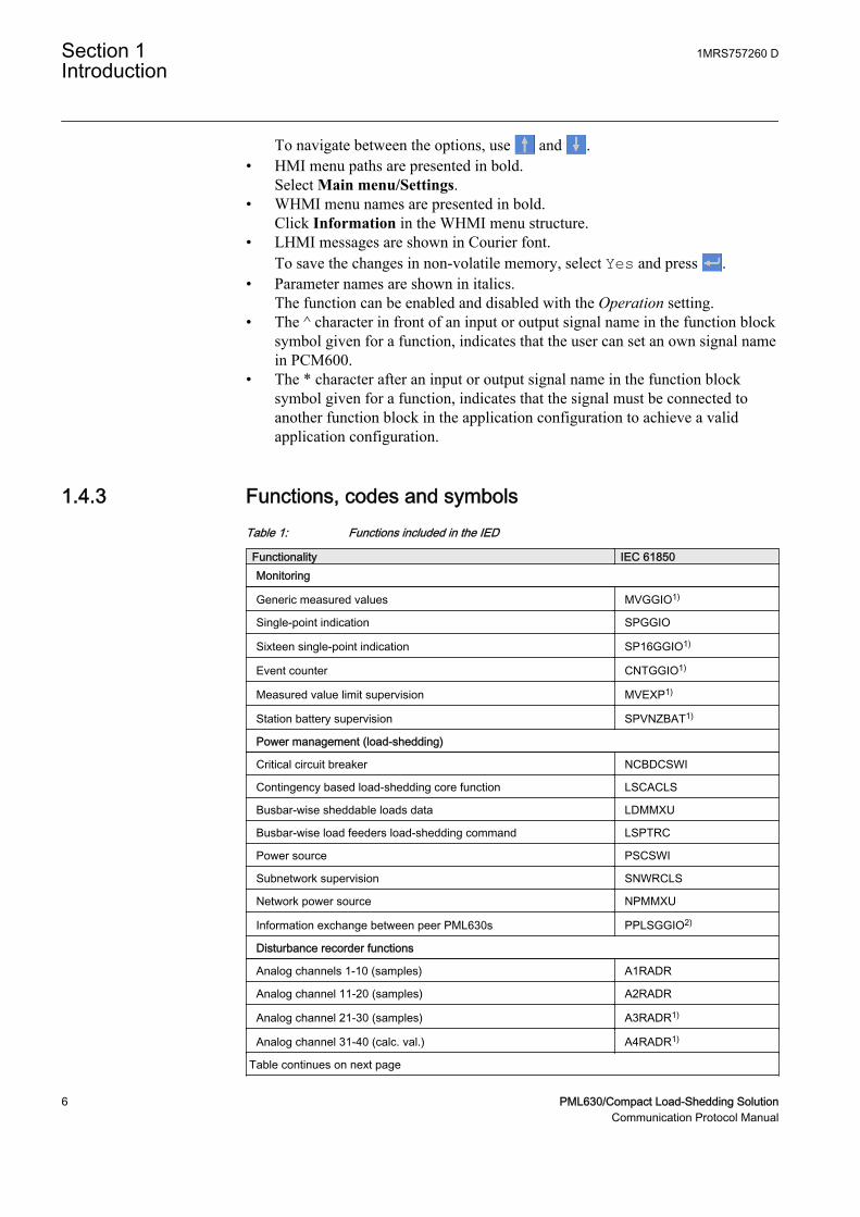
1.4.3 Functions, codes and symbolsTable 1: Functions included in the IED
Functionality IEC 61850Monitoring
Generic measured values MVGGIO1)
Single-point indication SPGGIO
Sixteen single-point indication SP16GGIO1)
Event counter CNTGGIO1)
Measured value limit supervision MVEXP1)
Station battery supervision SPVNZBAT1)
Power management (load-shedding)
Critical circuit breaker NCBDCSWI
Contingency based load-shedding core function LSCACLS
Busbar-wise sheddable loads data LDMMXU
Busbar-wise load feeders load-shedding command LSPTRC
Power source PSCSWI
Subnetwork supervision SNWRCLS
Network power source NPMMXU
Information exchange between peer PML630s PPLSGGIO2)
Disturbance recorder functions
Analog channels 1-10 (samples) A1RADR
Analog channel 11-20 (samples) A2RADR
Analog channel 21-30 (samples) A3RADR1)
Analog channel 31-40 (calc. val.) A4RADR1)
Table continues on next page
Section 1 1MRS757260 DIntroduction
6 PML630/Compact Load-Shedding SolutionCommunication Protocol Manual
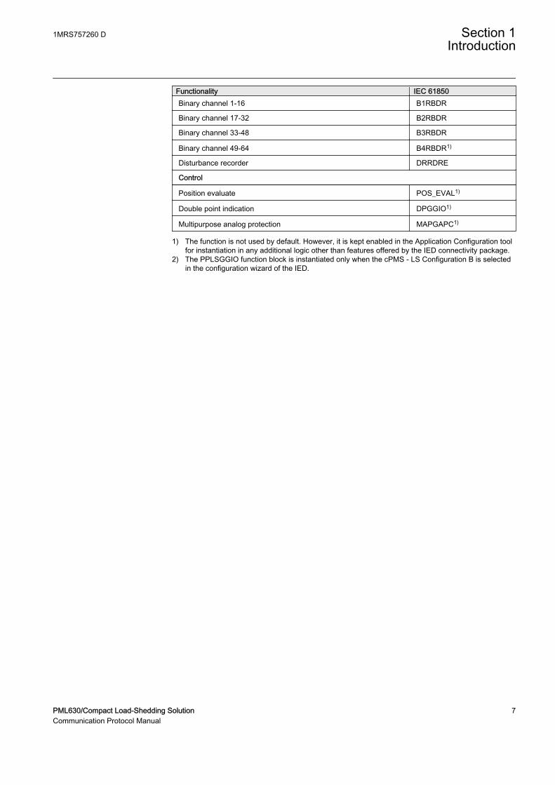
Functionality IEC 61850Binary channel 1-16 B1RBDR
Binary channel 17-32 B2RBDR
Binary channel 33-48 B3RBDR
Binary channel 49-64 B4RBDR1)
Disturbance recorder DRRDRE
Control
Position evaluate POS_EVAL1)
Double point indication DPGGIO1)
Multipurpose analog protection MAPGAPC1)
1) The function is not used by default. However, it is kept enabled in the Application Configuration toolfor instantiation in any additional logic other than features offered by the IED connectivity package.
2) The PPLSGGIO function block is instantiated only when the cPMS - LS Configuration B is selectedin the configuration wizard of the IED.
1MRS757260 D Section 1Introduction
PML630/Compact Load-Shedding Solution 7Communication Protocol Manual

8
Section 2 Introduction to IEC 61850
The IEC 61850 protocol standard for substation enables the integration of allprotection, control, measurement and monitoring functions by one commonprotocol. It provides the means of high-speed substation applications, station wideinterlocking and other functions requiring intercommunication between IEDs. Thewell described data modelling, the specified communication services for the mostrecent tasks in a station makes the standard to a key element in modern substationsystems.
This manual describes mainly how the IEC 61850 standard is applied in PML630.References and brief descriptions of the IEC 61850 standard are also included. It isassumed that the reader has basic knowledge about the IEC 61850.
To understand the IEC 61850 standard and to be able to find the relatedinformation, the following parts of the standard are of importance:
• Station Configuration description Language (SCL) is described in IEC61850-6. The SCL is an XML based definition of how to describe the parts ofa substation. This part of the standard also includes the roles of different toolsas well as the engineering concepts.
• Communication profile (IEC 61850 stack) is described in IEC 61850-8-1. Thispart of the standard includes a number of possible communication profiles, andhow the services defined in IEC 61850-7-2 are mapped to the communicationprofile.
• Communication services are described in IEC 61850-7-2. This part dealsmainly with the communication facilities from client and server point of view.It includes the different possibilities of communication functionality.
• Logical node data model. This is described in IEC 61850-7-3 and IEC61850-7-4.
• Conformance tests and the basis for conformance documents are handled inIEC 61850-10.
To get information and an understanding about the implemented possibilities ofIEC 61850 in the IED, the details are described in the IEC 61850 conformancedocuments.
• MICS, Modeling Information Conformance Statement, contains thedeclaration of the used logical node types.
• PICS, Protocol Information Conformance Statement, contains the details andwhat is supported regarding protocol facilities.
• PIXIT, Protocol Extra Information, contains additional information on how theIEC 61850 is implemented and used.
• TICS, Tissue Information Conformance Statement, contains the supportedTissues, which are handled in the Tissues process as defined by UCA, Utility
1MRS757260 D Section 2Introduction to IEC 61850
PML630/Compact Load-Shedding Solution 9Communication Protocol Manual
Communication Architecture forum. The Tissues handling is found inwww.tissues.iec61850.com.
The TICS for the 630 Series version 1.2 is also applicable for PML630 (as it isbased on 630 Series version 1.2) and, hence, a separate TICS document is not madefor the IED.
The conformance documents are unique for each product release and refer to eachother; the identities included in the related documents refer to a specific version ofthe IED.
The communication profile in IEC 61850 uses the MMS standard, which usesEthernet and TCP/IP to handle the information transport within the substation.
The data modelling uses the concept of logical nodes to identify the publishedinformation for communication. The standard defines a set of logical nodes, eachrepresenting a communication view of a process function with a number of dataobjects. The standard cannot cover all possible information that is given, forexample, by a protection function of vendor A or vendor B or for the variants of aprotection function given by the process part which is protected. For example, atransformer differential - or line differential protection, because the standarddefines only a differential protection. Therefore, it is possible to adapt the logicalnode, which is defined in the standard, as a logical node class. The standard definesmethods to describe the actually used logical node as a logical node type which isthen based upon the logical node class. This allows all partners to interpret thelogical node type information because the description is completely given in thestandard. The type description of all logical nodes is part of the Data TypeTemplate (DTT) section in the SCL description file of a station or the IED.
Besides the information about the configuration of the communication facilities,this manual contains the full description of all logical nodes available in the IED.The information about the logical nodes and their data objects may be used toidentify which signals are available for the functions as described in the technicalmanual. The link to the technical manual is done in the logical node tables bylisting the signal name as given in the function block, or as seen in PCM600 or theLHMI.
2.1.1 Related documentation to IEC 61850Use the latest revision of the documents listed, unless stated otherwise.
Section 2 1MRS757260 DIntroduction to IEC 61850
10 PML630/Compact Load-Shedding SolutionCommunication Protocol Manual
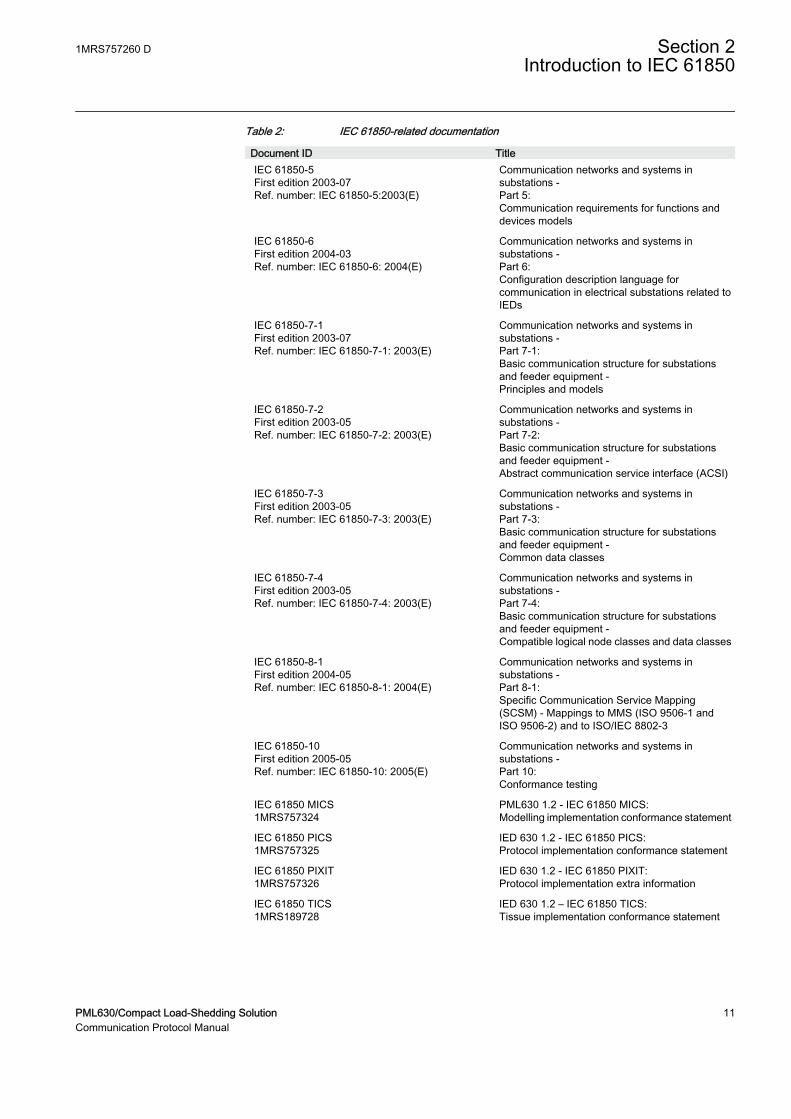
Table 2: IEC 61850-related documentation
Document ID TitleIEC 61850-5First edition 2003-07Ref. number: IEC 61850-5:2003(E)
Communication networks and systems insubstations -Part 5:Communication requirements for functions anddevices models
IEC 61850-6First edition 2004-03Ref. number: IEC 61850-6: 2004(E)
Communication networks and systems insubstations -Part 6:Configuration description language forcommunication in electrical substations related toIEDs
IEC 61850-7-1First edition 2003-07Ref. number: IEC 61850-7-1: 2003(E)
Communication networks and systems insubstations -Part 7-1:Basic communication structure for substationsand feeder equipment -Principles and models
IEC 61850-7-2First edition 2003-05Ref. number: IEC 61850-7-2: 2003(E)
Communication networks and systems insubstations -Part 7-2:Basic communication structure for substationsand feeder equipment -Abstract communication service interface (ACSI)
IEC 61850-7-3First edition 2003-05Ref. number: IEC 61850-7-3: 2003(E)
Communication networks and systems insubstations -Part 7-3:Basic communication structure for substationsand feeder equipment -Common data classes
IEC 61850-7-4First edition 2003-05Ref. number: IEC 61850-7-4: 2003(E)
Communication networks and systems insubstations -Part 7-4:Basic communication structure for substationsand feeder equipment -Compatible logical node classes and data classes
IEC 61850-8-1First edition 2004-05Ref. number: IEC 61850-8-1: 2004(E)
Communication networks and systems insubstations -Part 8-1:Specific Communication Service Mapping(SCSM) - Mappings to MMS (ISO 9506-1 andISO 9506-2) and to ISO/IEC 8802-3
IEC 61850-10First edition 2005-05Ref. number: IEC 61850-10: 2005(E)
Communication networks and systems insubstations -Part 10:Conformance testing
IEC 61850 MICS1MRS757324
PML630 1.2 - IEC 61850 MICS:Modelling implementation conformance statement
IEC 61850 PICS1MRS757325
IED 630 1.2 - IEC 61850 PICS:Protocol implementation conformance statement
IEC 61850 PIXIT1MRS757326
IED 630 1.2 - IEC 61850 PIXIT:Protocol implementation extra information
IEC 61850 TICS1MRS189728
IED 630 1.2 – IEC 61850 TICS:Tissue implementation conformance statement
1MRS757260 D Section 2Introduction to IEC 61850
PML630/Compact Load-Shedding Solution 11Communication Protocol Manual

12
Section 3 Substation Configuration descriptionLanguage (SCL)
The SCL language is based on XML. However, detailed knowledge of the XMLcontents is not needed.
The SCL XML file (ied.ICD and/or station.SCD) contains five sections, which arespecified in IEC 61850–6 clause 9.
• Header• Substation section describes the functional structure and its relation to primary
devices.• Communication section describes the connection between the IED access
points to the respective subnetwork. and includes also the properties(addresses) of the access points.
• IED section contains a description of the supported communication services,the access point(s) and the IEDs logical devices, logical nodes and their attributes.
• Data type template section contains a declaration of all types used in the SCLfile, logical nodes type, DO types, attributes and enums.
The substation section and the communication section are tasks to organize theIEDs within the substation and to establish the communication. The systemstructure is defined by the organization of the plant structure in PCM600. Thesignal engineering and the signal routing are IET600 tasks. The IED needs to beconfigured with PCM600 before the system is configured with IET600.
The IED section contains the data sets and the control blocks configured byIET600. The data sets and the control blocks are logically defined as part of thelogical nodes (see IEC 61850-7-2 clause 9). IET600 also needs a correctlyconfigured communication section for GOOSE engineering.
The data type templates section provides the correct content description of eachlogical node type to all tools and users (clients) of the information. Each IED andvendor may have their own logical node type definitions included in the data typetemplate section together with all other logical node types based on the standard.
1MRS757260 D Section 3Substation Configuration description Language (SCL)
PML630/Compact Load-Shedding Solution 13Communication Protocol Manual
IEC08000178.vsd
IED Name AccessPoint Address GSEIED Name AccessPoint Address GSE
Services
AuthenticationLDevice
DAI
DOType
DAType
EnumType
SubstationVoltageLevel
BayLNode
IED LD LNIED LD LN
CommunucationSubnetwork
Connected AP
IEDAccessPoint
Server
GOOSE Control
LN0 LNDataSet DOI
DataTypeTemplates
Report Control
Inputs
DOI
SettingControl
LNodeType
DOType
DAType
EnumType
DO
DA
IED
SDO
BDA
Stat
ion
Com
mun
IEC08000178 V1 EN
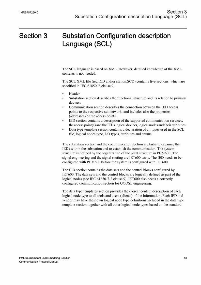
Figure 1: IEC 61850: Principle structure of the SCL XML file
The arrows show the link between the different sections given when an IED isintegrated in the substation structure and/or in the communication structure. Allneeded logical nodes of an IED are linked to the substation section by the systemconfiguration tool.
A reference to GOOSE Control Blocks (GoCB) is included in the communicationsection when GoCB is configured.
3.1 The substation section
The substation description in IEC 61850-6 clause 9 describes the organization ofthe primary equipment on one side. On the other side, it includes the used logicalnodes and their relation to the primary equipment.
3.2 The communication section
The organization of the physical IEDs to the communication network isindependent of the substation structure. The IEC 61850 standard defines the
Section 3 1MRS757260 DSubstation Configuration description Language (SCL)
14 PML630/Compact Load-Shedding SolutionCommunication Protocol Manual
communication network with no relation to an existing media and protocol. Themapping to an existing media and protocol is specified in IEC 61850-8-1.
The IEC 61850 standard describes in part 7-2 the ACSI in a media and protocolindependent form. Part 8-1 specifies the mapping of this ACSI to the existingMMS.
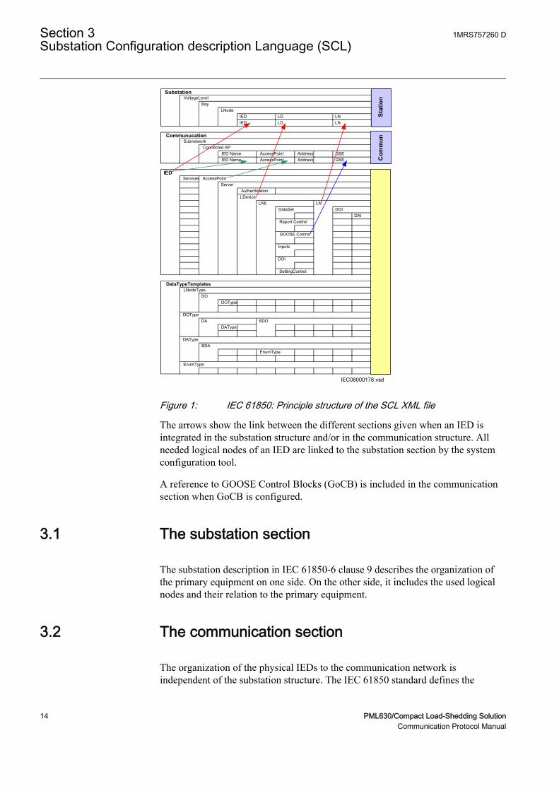
The communication section describes how information is routed between the IEDsand contains the following parts:
• Subnetworks• IEDs connected to different subnetworks• Access points per IED to subnetworks• Address• IP address of LAN network (is exceptionally part of the address elements)• Link to GoCB message in transmission direction (extended during signal
engineering and routing)
en06000101.vsd
IED(server)
- Access Point (AP)- Address- GSE; GoCBs
Communication
AP
IED(server)
- Access Point (AP)- Address- GSE; GoCBs
Communication
IED(server)
- Access Point (AP)- Address- GSE; GoCBs
Communication
AP
IED(client)
- Access Point (AP)- Address- GSE; GoCBs
Communication
IED(client)
- Access Point (AP)- Address- GSE; GoCBs
Communication
Subnetwork
IEC06000101 V1 EN
Figure 2: IEC 61850–6: Communication network
Additional information about the server is part of the IED.
3.3 The IED section
The IED section describes the complete IED as it is needed for IEC 61850communication and signal engineering. The data type template part of an IED maybe seen as part of the IED, even when separated in its own section. The IED's ICD
1MRS757260 D Section 3Substation Configuration description Language (SCL)
PML630/Compact Load-Shedding Solution 15Communication Protocol Manual
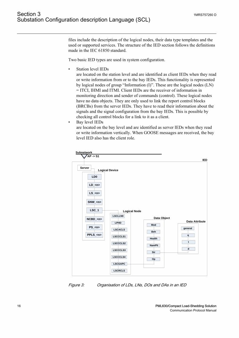
files include the description of the logical nodes, their data type templates and theused or supported services. The structure of the IED section follows the definitionsmade in the IEC 61850 standard.
Two basic IED types are used in system configuration.
• Station level IEDsare located on the station level and are identified as client IEDs when they reador write information from or to the bay IEDs. This functionality is representedby logical nodes of group “Information (I)”. These are the logical nodes (LN)= ITCI, IHMI and ITMI. Client IEDs are the receiver of information inmonitoring direction and sender of commands (control). These logical nodeshave no data objects. They are only used to link the report control blocks(BRCBs) from the server IEDs. They have to read their information about thesignals and the signal configuration from the bay IEDs. This is possible bychecking all control blocks for a link to it as a client.
• Bay level IEDsare located on the bay level and are identified as server IEDs when they reador write information vertically. When GOOSE messages are received, the baylevel IED also has the client role.
IED
Subnetwork
AP -> S1
ServerLogical Device
LD0
LD_<n>
LS_<n>
SNW_<n>
LSC_1
NCBD_<n>LSCLLN0
LPHD
LSCACLS
LSCCCLS1
LSCGAPC
LSCCCLS2
LSCCCLS3
LSCCCLS4
LSCRCLS
Logical Node
Mod
Beh
Health
NamPlt
Str
Op
Data Object
general
q
t
d
Data Attribute
PS_<n>
PPLS_<n>
GUID-76CB6EDD-208D-4F77-9EE6-6F3F9CA9D980 V2 EN
Figure 3: Organisation of LDs, LNs, DOs and DAs in an IED
Section 3 1MRS757260 DSubstation Configuration description Language (SCL)
16 PML630/Compact Load-Shedding SolutionCommunication Protocol Manual
• A server represents the communication interface to the subnetwork (Ethernet).• One or more logical device(s) (LD) are connected to a server.• A set of logical nodes belong to a LD.• The LN LLN0 is a special logical node per LD and contains for example the
data sets, the various control blocks, inputs (from GOOSE messages). In theIED, the data sets and the control blocks shall be located to LD0.
• The LN LPHD is a special logical node per LD and contains data objects thatdescribe the status of the physical device (the IED)
• Each logical node represents a function and contains a number of data objects(DO)
• Each DO includes a number of data attributes (DA)
The data objects represent information signals that may be routed to station levelIEDs or to other bay IEDs that are communicating with GOOSE. The signalengineering task is to select the requested signals (DOs) and link them to the clientIEDs as receiver. The control services are not directly engineered. They areincluded in the data objects, which handle both directions the command (control)and the response (monitoring). When routing the DO in monitoring direction, thecontrol is also known by the clients.
The number of data objects and data attributes per DO is defined by the used LNtype in this IED. The content of logical node types and DO types are defined in theDTT. This also means that the definitions in the DTT section have to be uniquewith an SCD file.
3.4 Tool concept
The IEC 61850-6 defines a number of roles for tools. In the Relion® series,PCM600 is defined as the IED tool, and IET600 is defined as the systemengineering tool.
The sections in SCL contain properties that are to be configured by these tools.There is no relation between one section and one specific tool. The task of the IEDtool is to configure all properties for the IED, while the system tool has the task todefine the place of the IED in the system and its communication dependencies. Forexample, the plant structure in PCM600 results in the subsystem section in SCLregarding the subsystem structure down to the IED level. PCM600 also configuresthe IED section as a result of the IED configuration. In PCM600, the configurationproperties for SCL are handled automatically as a result of the configuration,except for the receiving of GOOSE information that has a dependency with thesystem tool.
1MRS757260 D Section 3Substation Configuration description Language (SCL)
PML630/Compact Load-Shedding Solution 17Communication Protocol Manual
3.4.1 IEC 61850 engineering with PCM600 and IET600
PCM600• When an IED is instantiated, its place in the plant structure creates the
corresponding structure in the substation section in SCL. The communicationfacilities are also created in the communication section.
• The functionality of the IED is configured by using ACT in PCM600. For eachfunction, the corresponding logical device and logical node(s) are created inthe IED section together with its type definition in the data type template section
• The above forms the IED capabilities from a communication perspective andwill then be included in the file exported from PCM600 as a SCD, ICD or CIDfile
IET600• Open a SCD file or import/merge a SCD, ICD or CID file for the particular
IED(s).• For each IED, the user defines the data sets, the control blocks for reporting
(this means unbufffered/buffered reporting and GOOSE) and the properties foreach report control block.
• If client definitions (like client. ICD) are required in the system configuration,they are merged into IET600 and connected to the unbuffered/buffered reportcontrol blocks.
• For each IED, the primary/conducting equipment with their relation to theused logical nodes must be defined in the substation section.
• Logical nodes, which are not related to the conducting equipment, must beincluded in the bay level in the substation section.
• The resulting SCD file is exported from IET600.
PCM600Import the SCD file to PCM600 to receive GOOSE data. For each IED that shallreceive GOOSE information, the received data is connected to the applicationsusing SMT in PCM600.
3.5 Engineering concept in IEC 61850-6
• Top-down approach means that the system engineering tool has ICD filesavailable for each IED to be included in the system configuration. The ICDfiles may be of an template type and represent a pre-configured IED.
• Bottom-up approach means that the configurations are produced by the IEDtool, and that are exported as ICD files (or SCD file) to be imported by systemtools.
Section 3 1MRS757260 DSubstation Configuration description Language (SCL)
18 PML630/Compact Load-Shedding SolutionCommunication Protocol Manual

….IED A IED B IED Z
Client A Client B
IEDtool
Systemtool
GUID-ACC3CE26-A7F7-4B88-A6DD-9B5104A5A10F V1 EN
Figure 4: Relation between system and IED tools
Regardless of engineering approach, the idea is that the IED tool provides the CIDor ICD file for each IED. These ICD/CID files are then imported into the systemtool and merged into an SCD file, representing the complete substation or a part ofthe substation, like one for each voltage level.
1MRS757260 D Section 3Substation Configuration description Language (SCL)
PML630/Compact Load-Shedding Solution 19Communication Protocol Manual

20

Section 4 Communication profile
The IEC 61850 standard is conceptually written to be independent of an existingcommunication media and message transmission concept. Out of this, a specificcommunication profile is decided and is been commonly used. The actual decisionis for
• Ethernet as the media• TCP/IP• ISO session and presentation layer• MMS (Manufacturing Message Specification (ISO 9506-1 and ISO 9506-2)
The IEC 61850 standard describes its requested services in ACSI, which iscontained in part 7-2 of the standard. The mapping to the MMS for all aspects ofservices and Ethernet usage is specified in part 8-1 of IEC 61850.
Each device manufacturer, which is a partner of an IEC 61850-basedcommunication network, has to take these two specifications and adapt theirrespective product to the requirements and definitions given in the standard. Tomake this profile visible to all other partners, so they can check what they canexpect and what they have to support, the PICS document is defined. The PICScontains in a table based form the possibility of a product or product family.
IED (server )(61850 services part 7-2)
Communication(MMS services part 8-1)
- Access Point (AP) / Address- GSE
AP
IED (client )(61850 services part 7-2)
Subnetwork
IED (server)(61850 services part 7-2)
Communication(MMS services part 8-1)
Communication( MMS servicespart 8-1)
- Access Point (AP) / Address- GSE
- Access Point (AP) / Address- GSE
GUID-5E41938B-BF64-4A80-8012-77DFF0D9D92D V1 EN
Figure 5: IEC 61850 Protocol: related standards for communication
1MRS757260 D Section 4Communication profile
PML630/Compact Load-Shedding Solution 21Communication Protocol Manual
SV GOOSE TimeSync(SNTP) MMS Protocol Suite GSSE
TCP/IPT-Profile
ISO COT-Profile
ISO/IEC 8802-2 LLC
GSSET-ProfileUDP/IP
ISO/IEC 8802-3 Ethertype
SampledValues(Multicast)
GenericObjectOrientedSubstationEvent
TimeSync
CoreACSIServices
GenericSubstationStatusEvent
ISO/IEC 8802-3GUID-8CA0E976-7104-4170-A92F-188D333E4C25 V1 EN
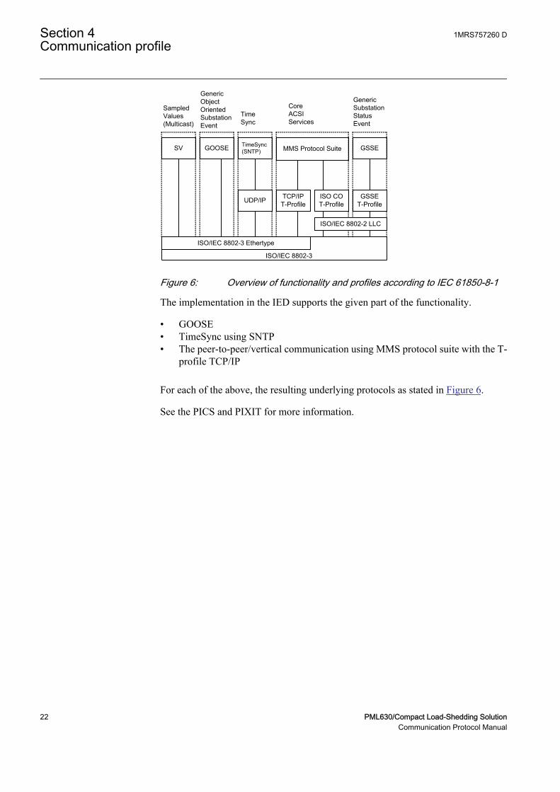
Figure 6: Overview of functionality and profiles according to IEC 61850-8-1
The implementation in the IED supports the given part of the functionality.
• GOOSE• TimeSync using SNTP• The peer-to-peer/vertical communication using MMS protocol suite with the T-
profile TCP/IP
For each of the above, the resulting underlying protocols as stated in Figure 6.
See the PICS and PIXIT for more information.
Section 4 1MRS757260 DCommunication profile
22 PML630/Compact Load-Shedding SolutionCommunication Protocol Manual
Section 5 Supported services
IEC 61850-7-2 describes the services in the standard. IEC 61850-8-1 describeshow the services are applied in the communication. The conformance documentscontain the main description about the supported services in the IED.
Services that are not mentioned in this chapter or in the conformance document arenot supported.
Data setDefine data sets by the SCD description.
Create data sets under LD0/LLN0.
Report control blockFor properties about report control blocks, see PIXIT.
UnBuffered reporting as well as Buffered reporting is supported.
The relation between the parameters BufTm and IntPrd is BufTm <IntPrd. For best efficiency, the BufTm must have IntPrd as commondenominator, like n*BufTm = IntPrd, n is an arbitrary number.
Generic substation event (GOOSE)The structured GOOSE is supported. This means that the data sets can be definedwith FCDA as well as explicit attributes.
When explicit attributes are defined in the data sets, the number of such items in adata set is limited to 300.
The supported data types to be published and received using GOOSE includemeasurement, single point and double point status information together with theirquality. On reception of GOOSE message there is one valid signal available for theapplications. The valid signal represents all data in the received GOOSE telegram.Invalid means that the correct message is not received within the 1.8*maxTimeparameter for the GOOSE Control Block (as defined in IEC 61850-6). An incorrectmessage includes T=true, NeedsCom, wrong order of attributes or any discrepancyin the GOOSE message layout.
The data sets that are used or referred to by GOOSE control blockscan only include a data attribute once. In other words, there may notbe the same data attribute in more than one data set.
1MRS757260 D Section 5Supported services
PML630/Compact Load-Shedding Solution 23Communication Protocol Manual
ControlOf the different control sequences, the direct-with-normal-security and SBO-withenhanced security are supported (defined by the ctlModel parameter, IEC61850-7-2).
The command model can be changed for some functions by using PCM600 orLHMI. From communication perspective, in IEC61850 this parameter is read-only.
Check bits; interlock check and synchrocheck check, are only valid for LN typesbased upon CSWI class.
Verification of Originator Category is supported, see PIXIT.
Time and time synchronizationFor properties about time synchronization, see PIXIT and Time synchronizationdescription in the Technical manual and the Application engineering guide.
File transferSee PIXIT.
Section 5 1MRS757260 DSupported services
24 PML630/Compact Load-Shedding SolutionCommunication Protocol Manual
Section 6 Data sets and control blocks
6.1 Data sets
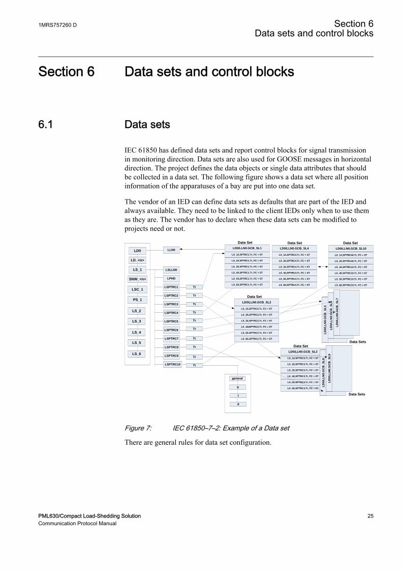
IEC 61850 has defined data sets and report control blocks for signal transmissionin monitoring direction. Data sets are also used for GOOSE messages in horizontaldirection. The project defines the data objects or single data attributes that shouldbe collected in a data set. The following figure shows a data set where all positioninformation of the apparatuses of a bay are put into one data set.
The vendor of an IED can define data sets as defaults that are part of the IED andalways available. They need to be linked to the client IEDs only when to use themas they are. The vendor has to declare when these data sets can be modified toprojects need or not.
LD0 LLN0
LD_<n>
LS_1
SNW_<n>
LSC_1
PS_1
LSLLN0
LPHD
LSPTRC1
LSPTRC2
LSPTRC3
LSPTRC4
LSPTRC5
LSPTRC6
LSPTRC7
LSPTRC8
LSPTRC9
LSPTRC10
Tr
Tr
Tr
Tr
Tr
Tr
Tr
Tr
Tr
Tr
LD0/LLN0.GCB_SL1
LS_1/LSPTRC1.Tr, FC = ST
LS_2/LSPTRC1.Tr, FC = ST
LS_3/LSPTRC1.Tr, FC = ST
LS_4/LSPTRC1.Tr, FC = ST
LS_5/LSPTRC1.Tr, FC = ST
LS_6/LSPTRC1.Tr, FC = ST
general
q
t
d
Data Set
LS_2
LS_3
LS_4
LS_5
LS_6
LD0/LLN0.GCB_SL2
LS_1/LSPTRC2.Tr, FC = ST
LS_2/LSPTRC2.Tr, FC = ST
LS_3/LSPTRC2.Tr, FC = ST
LS_4/LSPTRC2.Tr, FC = ST
LS_5/LSPTRC2.Tr, FC = ST
LS_6/LSPTRC2.Tr, FC = ST
Data Set
LD0/LLN0.GCB_SL3
LS_1/LSPTRC3.Tr, FC = ST
LS_2/LSPTRC3.Tr, FC = ST
LS_3/LSPTRC3.Tr, FC = ST
LS_4/LSPTRC3.Tr, FC = ST
LS_5/LSPTRC3.Tr, FC = ST
LS_6/LSPTRC3.Tr, FC = ST
Data Set
LD0/LLN0.GCB_SL4
LS_1/LSPTRC4.Tr, FC = ST
LS_2/LSPTRC4.Tr, FC = ST
LS_3/LSPTRC4.Tr, FC = ST
LS_4/LSPTRC4.Tr, FC = ST
LS_5/LSPTRC4.Tr, FC = ST
LS_6/LSPTRC4.Tr, FC = ST
LD0/LLN0.GCB_SL10
LS_1/LSPTRC40.Tr, FC = ST
LS_2/LSPTRC40.Tr, FC = ST
LS_3/LSPTRC10.Tr, FC = ST
LS_4/LSPTRC10.Tr, FC = ST
LS_5/LSPTRC10.Tr, FC = ST
LS_6/LSPTRC10.Tr, FC = ST
LD
0/L
LN
0.G
CB
_S
L5
LD
0/L
LN
0.G
CB
_S
L6
LD
0/L
LN
0.G
CB
_S
L7
LD
0/L
LN
0.G
CB
_S
L8
LD
0/L
LN
0.G
CB
_S
L9
Data Set Data Set
Data Sets
Data Sets
s
GUID-62C9029B-6DA8-4D40-9B54-28863BDB34B6 V2 EN
Figure 7: IEC 61850–7–2: Example of a Data set
There are general rules for data set configuration.
1MRS757260 D Section 6Data sets and control blocks
PML630/Compact Load-Shedding Solution 25Communication Protocol Manual
• All data objects or their data attributes which are signals in monitoringdirection can be selected for a data set.
• Items in a data set are normally added by the DO name and functionalconstraint. All attributes within the DO with the same functional constraint areincluded in the data set.
• Data objects with different FC can be selected for a data set. For example,DOs with FC = ST and DOs with FC=MX can be member in one data set.
• A single data attribute can be selected when it is specified with a triggeroption. For example, the data attribute stVal of the data object Pos can beselected as a member of a data set, because it is specified with the triggeroption data change detected (dchg).
The criteria for reporting are defined in the respective report control block. As theattributes have different trigger options, the most feasible configuration is toinclude attributes with the same trigger option, but it is also possible to define anumber of reporting conditions for one report control block.
The description of the data sets with name and the list of data object members(FCDAs is included in the SCL file in the IED section in the Logical devicesubsection. As specified in IEC 61850-7-2 clause 9, the data sets are part of alogical node. For the Relion product family, the data sets can be defined in LD0/LLN0.
6.2 Report control block (URCB/BRCB)
To be able to transmit the signals configured in a data set, a report control blockmust be configured to handle and specify how the events are transmitted to theclients. There are two types of report control blocks; unbuffered and buffered. Thebuffered report control block stores the events during a communication interrupt,while the unbuffered is sent upon data change and not stored during interruption.
The content of a BRCB is listed in IEC 61850-7-2 in clause 14. The BRCBcontains many attributes which are of interest to handle and secure thecommunication between the client and the server and may be set once as default ina project. Others are of application interest in the way events are handled in a project.
• Buffer time (valid only for BRCB)• This parameter describes how long the report should wait for other
expected events before it sends the report to the client. When it is known,that additional events are generated as a follow up, it is useful to wait,for example, 500 ms for additional events stored in the report. Thisfeature reduces the number of telegrams transmitted in case of a burst ofchanges. But on the other side it increases the overall transaction time forevents from IED input to presentation on HSI, which is normally definedto be one second.
• Trigger options
Section 6 1MRS757260 DData sets and control blocks
26 PML630/Compact Load-Shedding SolutionCommunication Protocol Manual
• The data attributes know three different trigger options (dchg, qchg,dupd). Within the BRCB, the two other can be defined (integrity andgeneral interrogation). The attribute Trigger option is a multiple choiceand allows to mask the supported trigger options in this BRCB.
• Integrity period• When integrity is selected in the trigger option attribute, it is needed to
define an integrity period to force the transmission of all data listed inthe data set. This is done by the attribute Integrity period. This featurecan be used as a background cycle to ensure that the process image in allpartners is the same. The background cycle can repair a lost event in thechain from the NCC to an IED.
• General interrogation• A general interrogation is only done on request from a client. Not all
data sets may contain information which is needed for a general updateof the client. For example data with T(ransient) = TRUE are not part of aGI. When the BRCB attribute general interrogation is set to TRUE a GIrequest from the client will be handled. The report handler will transmitall data defined in the data set with their actual values. The IEC 61850standard defines that all buffered events shall be transmitted first beforethe GI is started. A running GI shall be stopped and a new GI shall bestarted, when a new GI request is received while a GI is running.
• Purge buffer (valid only for BRCB)• This BRCB attribute can be used by a client to clean the event buffer
from old events. The events are discarded on request of the client. Thisfeature can be used to delete old events not transmitted to the client dueto stopped communication. After the link is reestablished the client candecide to clean the buffer or to receive the history.
Trigger OptionsIEC 61850 has defined in total five different TrgOp. Three of them belonging todata attributes and marked per data attribute in the column TrgOp of the CDCtables in part 7–3. The other two belonging to the configuration of control blocks.
• dchg = data-change• The classical trigger. Whenever a process value has changed its value
either binary or a measurement a transmission is done. The standard doesnot define how to detect and inform the logical node.
• qchg = quality change• Looking to the possibilities of the quality data attribute type (q) any
changes in the quality description will be transmitted.• dupd = data value update
• This trigger option give the possibility to define that a transmissionshould be done on a condition which can be controlled by the application.
• integrity
1MRS757260 D Section 6Data sets and control blocks
PML630/Compact Load-Shedding Solution 27Communication Protocol Manual

• This trigger forces the transmission of all process values defined in thedata set when a timer value (the integrity period) expires. It can be usedfor example to update a process signal in the background (for example,every 15 minutes).
• general interrogation• This trigger is forced by the clients (= station level IED; NCC gateway,
station HMI, ...). Normally a GI is asked for, when the client and theserver start or restart a session. When the client is able to receive theactual values and when the logical device has scanned all process valuesat least once, an image of the actual process signal status can betransmitted to the client.
Note that the possible trigger options for each attributeare included and defined in the data type template sectionin SCL.
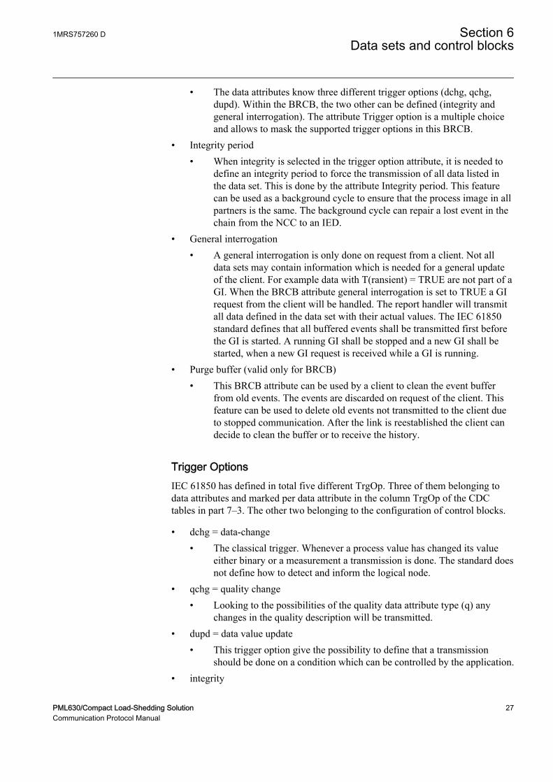
Link BRCB to a client LNThe BRCB has to know to whom the events shall be transmitted. This is the signalrouting engineering step. The IEC standard 61850–6 describes that this is given byincluding the LN of the client IED in the ReportBlockEnabled option.
The selected client IED with the corresponding LN, for example, ITCI is includedin the SCL structure of the Report Control description of the IED section.
The description of the BRCB with the selected data set, configured parameters andselected IEDs is included in the SCL file in the IED section in the LN0 structurefor the LD where this LN0 belongs to.
Section 6 1MRS757260 DData sets and control blocks
28 PML630/Compact Load-Shedding SolutionCommunication Protocol Manual
.
IEDHSI
Client 1
IEDNCC GW 1
Client 2
IEDNCC GW m
Client 5
IED 1
Server 1
Subnetwork
ITCI2ITCI1IHSI1
LLN0 LD0/LLN0.StatUrg (for feeder status, priority and load shed inhibit status)
LD_1/MMXU1.InhLSSt, FC = ST
LD_1/MMXU1.LodPrioSt, FC = ST
LD_1/CSWI1.Pos, FC = ST
LD_1/MMXU2.InhLSSt, FC = ST
LD_1/MMXU2.LodPrioSt, FC = ST
LD_1/CSWI2.Pos, FC = ST
LD_1/MMXU3.InhLSSt, FC = ST
LD_1/MMXU3.LodPrioSt, FC = ST
LD_1/CSWI3.Pos, FC = ST
LD_1/MMXU4.InhLSSt, FC = ST
LD_1/MMXU4.LodPrioSt, FC = ST
LD_1/CSWI4.Pos, FC = ST
LD_1/MMXU5.InhLSSt, FC = ST
LD_1/MMXU5.LodPrioSt, FC = ST
LD_1/CSWI5.Pos, FC = ST
LD_1/MMXU6.InhLSSt, FC = ST
LD_1/MMXU6.LodPrioSt, FC = ST
LD_1/CSWI6.Pos, FC = ST
LD_1/MMXU7.InhLSSt, FC = ST
LD_1/MMXU7.LodPrioSt, FC = ST
LD_1/CSWI7.Pos, FC = ST
LD_1/MMXU8.InhLSSt, FC = ST
LD_1/MMXU8.LodPrioSt, FC = ST
LD_1/CSWI8.Pos, FC = ST
LD_1/MMXU9.InhLSSt, FC = ST
LD_1/MMXU9.LodPrioSt, FC = ST
LD_1/CSWI9.Pos, FC = ST
LD_1/MMXU10.InhLSSt, FC = ST
LD_1/MMXU10.LodPrioSt, FC = ST
LD_1/CSWI10.Pos, FC = ST
GUID-228080DE-F70A-4E6C-AB08-F6ED10C320A3 V1 EN
Figure 8: Link BRCB to a client LN
1MRS757260 D Section 6Data sets and control blocks
PML630/Compact Load-Shedding Solution 29Communication Protocol Manual
6.3 GOOSE Control Blocks (GoCB)
Sen
d
Data-set
Rec
eive
Rec
eive
LNLN
LNLN
LN
Sen
d
Data-set
Rec
eive
Rec
eive
LNLN
LN LN
Sen
d
Data-setR
ecei
ve
Rec
eive
LN
LNLNLNLN
LN
Subnetwork
LN0
GoCB
DataSet
InputGoCBGoCB
DataSetDataSet
InputInput
Comm.GSE
LD1
Server
LN0
GoCB
DataSet
InputGoCBGoCB
DataSetDataSet
InputInput
Comm.GSE
LD1
Server
GUID-3AB50F10-A51C-4515-A936-74661339FC81 V1 EN
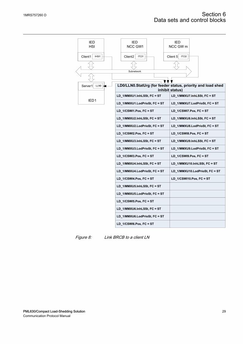
Figure 9: IEC 61850: Principle operation of GOOSE messages
The Generic object oriented substation event (GOOSE) class model is used todistribute input and output data values between IEDs on bay level (in horizontaldirection) through the use of multicast services. GOOSE messages bypass theserver and enable fast transmission from a publisher to one or several subscribers(receivers).
GOOSE messages are unidirectional, send only messages which request anapplication specific method to secure that the sender and the receiver of themessage operate safely. This implies that the receiver of the GOOSE messagedistributes also GOOSE messages and closes the loop for communication (request— respond on application level). The return message is not a must. It depends onthe application in which way a confirmation may be done.
Section 6 1MRS757260 DData sets and control blocks
30 PML630/Compact Load-Shedding SolutionCommunication Protocol Manual
The GOOSE service model of IEC 61850-7-2 provides the possibility for fast andreliable system-wide distribution of input and output data values. Thisimplementation uses a specific scheme of re-transmission to achieve theappropriate level of reliability. When a GOOSE server generates aSendGOOSEMessage request, the current data set values are encoded in a GOOSEmessage and transmitted on the multicast association. The event that causes theserver to invoke a SendGOOSE service is a local application issue as defined inIEC 61850-7-2. Each update may generate a message in order to minimizethroughput time.
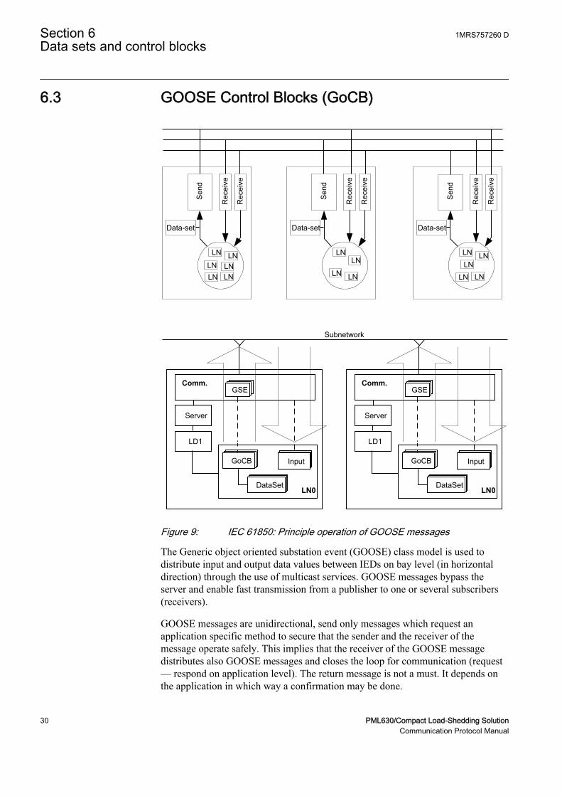
Additional reliability is achieved by re-transmitting the same data (with graduallyincreasing SqNum and retransmission time).
T0 retransmission in stable conditions (no event for a long time)
(T0) retransmission in stable conditions may be shortened by an event
T1 shortest retransmission time after the event
T2, T3 retransmission times until achieving the stable conditions time
Time of transmission
T0 (T0) T1 T1 T2 T3 T0
eventGUID-2B4B6A9D-16F6-4D8A-804D-D964E57B580A V1 EN
Figure 10: Transmission time for events
Each message in the retransmission sequence carries a timeAllowedToLiveparameter that informs the receiver of the maximum time to wait for the next re-transmission. If a new message is not received within that time interval, thereceiver assumes that the association is lost. The specific intervals used by anyGOOSE publisher are a local issue. The timeAllowedToLive parameter informssubscribers of how long to wait. In 630 series, to which PML630 belongs, thedetection time is 1.8 x timeAllowedToLive to cope with possible transmission delays.
The GOOSE message concept is used for all application functions where two ormore IEDs are involved. Typical example is the station-wide interlockingprocedure or breaker failure protection.
Figure 9 shows the GOOSE concept for three IEDs which interchange GOOSEmessages between each other.
1MRS757260 D Section 6Data sets and control blocks
PML630/Compact Load-Shedding Solution 31Communication Protocol Manual
To send GOOSE messages a GoCB must be defined and a data set is needed thatcontains the data objects of single data attributes to be send.
A GOOSE message is forced to be transmitted when a trigger change is detectedfor a data attribute. All members of the data set are copied in the send buffer withtheir actual value and the message is sent. The subscribers, who knows the addressof this GOOSE message, receives the telegram. The GOOSE message includes forexample sequence number to verify that all messages are received.
The concept that has to be done in case of for example a lost message is part of theapplication and not described in the standard.
A GoCB has to be defined per GOOSE-DataSet.
GOOSE messages bypass the server and send direct from the communication parton the Ethernet. This is identified for the communication in the SCLcommunication section in the GSE element, where the name of the GoCB is listedunder the ConnectedAP.
Link GoCB to an IEDThe IEDs that should receive the GOOSE message must be known and they haveto be informed in the engineering state that they receive GOOSE messages andwhich one. This is given when the external Reference, the name of the IED and themember of the data set is included in the LN0 under the structure of the LD of thereceiving IED. This part is identified as Inputs.
Section 6 1MRS757260 DData sets and control blocks
32 PML630/Compact Load-Shedding SolutionCommunication Protocol Manual

Section 7 Logical node data model
The data model used by IEC 61850 is based on logical nodes containing a set ofdata objects. The data model is defined in the standards.
• IEC 61850-7-4 Compatible logical node classes and data classes• IEC 61850-7-3 Common data classes
The standard describes only classes of logical nodes and data objects on one sideand common data classes for the data object attributes. The elements in theseclasses have certain definitions.
• Mandatory (M)• Optional (O)• Conditional optional (Cxxx)• In addition, IEC 61850 states rules for adding vendor-specific definitions to
the standard, in order to cope with extra functionality.
The possible description of the data model according to the standard allows toadapt a logical node of a LN class to that what the product is supporting or usingfor this LN. This definition of what parts of a class is used in the actual product andpossible addition is called a type, according to IEC 61850-6. There are LN typesbased upon LN classes. The LN type attributes are called Data Objects (or DATA)and are in of DO types, base upon respective CDC class. This allows all partners inthe IEC 61850 project who need this LN to understand the LN in all details for thecommunication part.
The IEC 61850 standard does not describe the functionality and way of operation.Each supplier has to describe this separately. ABB has described their functionblocks that represent a logical node and all other function blocks in the technicalmanuals. This chapter in the communication protocol manual has two tasks:
• Describe the Logical Node types and their data object attribute types.• Make the link to the description of the function block.
7.1 Common data objects in each logical node
The IEC 61850 standard describes in part 7-4, a Common Logical Node. The dataobjects contained in that LN are both mandatory and optional. The mandatory dataobjects have to be included in each LN. This clause describes the general handlingof the data objects within the 630 series products.
1MRS757260 D Section 7Logical node data model
PML630/Compact Load-Shedding Solution 33Communication Protocol Manual
The mandatory data objects as defined in IEC 61850-7-4 as part of the CommonLogical Node are Mode, Behavior, Health and NamePlate.
Mode
The operation modes ON (enabled) and BLOCKED are supported remotely by acommand or locally from the LHMI of the IED. The TEST and the TEST/BLOCKED mode can be operated locally from the LHMI or by using PCM600.
The state OFF can be set from the LHMI or by using PCM600 for the functionshaving the setting 'operation'.
Note also that for functions in other Logical devices than LD0, the Mod can onlybe controlled by communication on LLN0.
Behaviour
The operational mode as given by the Mode control is shown in the data object Behwith the priority rules as described for Beh in clause 6 of IEC 61850-7-4.
The Beh shows the actual state of the function, dependent upon the hierarchydescribed in IEC 61850-7-4, clause 6.
Health
The 630 series products show always only the state "green" = Ok.
NamePlt
The name of the logical node and its relation to namespace definition are shown inthe data object NamePlt as specified for the SCL structure.
7.2 Logical nodes for control
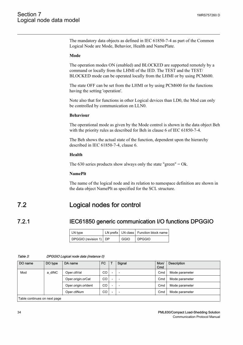
7.2.1 IEC61850 generic communication I/O functions DPGGIO
LN type LN prefix LN class Function block name
DPGGIO (revision 1) DP GGIO DPGGIO
Table 3: DPGGIO Logical node data (instance 0)
DO name DO type DA name FC T Signal Mon/Cmd
Description
Mod a_dINC Oper.ctlVal CO - - Cmd Mode parameter
Oper.origin.orCat CO - - Cmd Mode parameter
Oper.origin.orIdent CO - - Cmd Mode parameter
Oper.ctlNum CO - - Cmd Mode parameter
Table continues on next page
Section 7 1MRS757260 DLogical node data model
34 PML630/Compact Load-Shedding SolutionCommunication Protocol Manual
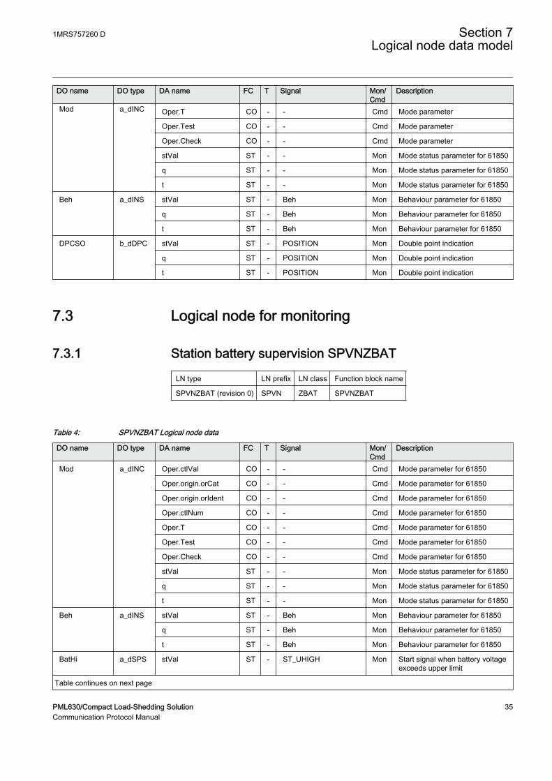
DO name DO type DA name FC T Signal Mon/Cmd
Description
Mod a_dINC Oper.T CO - - Cmd Mode parameter
Oper.Test CO - - Cmd Mode parameter
Oper.Check CO - - Cmd Mode parameter
stVal ST - - Mon Mode status parameter for 61850
q ST - - Mon Mode status parameter for 61850
t ST - - Mon Mode status parameter for 61850
Beh a_dINS stVal ST - Beh Mon Behaviour parameter for 61850
q ST - Beh Mon Behaviour parameter for 61850
t ST - Beh Mon Behaviour parameter for 61850
DPCSO b_dDPC stVal ST - POSITION Mon Double point indication
q ST - POSITION Mon Double point indication
t ST - POSITION Mon Double point indication
7.3 Logical node for monitoring
7.3.1 Station battery supervision SPVNZBAT
LN type LN prefix LN class Function block name
SPVNZBAT (revision 0) SPVN ZBAT SPVNZBAT
Table 4: SPVNZBAT Logical node data
DO name DO type DA name FC T Signal Mon/Cmd
Description
Mod a_dINC Oper.ctlVal CO - - Cmd Mode parameter for 61850
Oper.origin.orCat CO - - Cmd Mode parameter for 61850
Oper.origin.orIdent CO - - Cmd Mode parameter for 61850
Oper.ctlNum CO - - Cmd Mode parameter for 61850
Oper.T CO - - Cmd Mode parameter for 61850
Oper.Test CO - - Cmd Mode parameter for 61850
Oper.Check CO - - Cmd Mode parameter for 61850
stVal ST - - Mon Mode status parameter for 61850
q ST - - Mon Mode status parameter for 61850
t ST - - Mon Mode status parameter for 61850
Beh a_dINS stVal ST - Beh Mon Behaviour parameter for 61850
q ST - Beh Mon Behaviour parameter for 61850
t ST - Beh Mon Behaviour parameter for 61850
BatHi a_dSPS stVal ST - ST_UHIGH Mon Start signal when battery voltageexceeds upper limit
Table continues on next page
1MRS757260 D Section 7Logical node data model
PML630/Compact Load-Shedding Solution 35Communication Protocol Manual
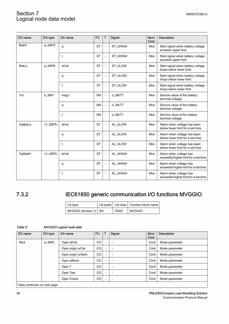
DO name DO type DA name FC T Signal Mon/Cmd
Description
BatHi a_dSPS q ST - ST_UHIGH Mon Start signal when battery voltageexceeds upper limit
t ST - ST_UHIGH Mon Start signal when battery voltageexceeds upper limit
BatLo a_dSPS stVal ST - ST_ULOW Mon Start signal when battery voltagedrops below lower limit
q ST - ST_ULOW Mon Start signal when battery voltagedrops below lower limit
t ST - ST_ULOW Mon Start signal when battery voltagedrops below lower limit
Vol b_dMV mag.f MX - U_BATT Mon Service value of the batteryterminal voltage
q MX - U_BATT Mon Service value of the batteryterminal voltage
t MX - U_BATT Mon Service value of the batteryterminal voltage
OpBatLo v1_dSPS stVal ST - AL_ULOW Mon Alarm when voltage has beenbelow lower limit for a set time
q ST - AL_ULOW Mon Alarm when voltage has beenbelow lower limit for a set time
t ST - AL_ULOW Mon Alarm when voltage has beenbelow lower limit for a set time
OpBatHi v1_dSPS stVal ST - AL_UHIGH Mon Alarm when voltage hasexceeded higher limit for a set time
q ST - AL_UHIGH Mon Alarm when voltage hasexceeded higher limit for a set time
t ST - AL_UHIGH Mon Alarm when voltage hasexceeded higher limit for a set time
7.3.2 IEC61850 generic communication I/O functions MVGGIO
LN type LN prefix LN class Function block name
MVGGIO (revision 1) MV GGIO MVGGIO
Table 5: MVGGIO Logical node data
DO name DO type DA name FC T Signal Mon/Cmd
Description
Mod a_dINC Oper.ctlVal CO - - Cmd Mode parameter
Oper.origin.orCat CO - - Cmd Mode parameter
Oper.origin.orIdent CO - - Cmd Mode parameter
Oper.ctlNum CO - - Cmd Mode parameter
Oper.T CO - - Cmd Mode parameter
Oper.Test CO - - Cmd Mode parameter
Oper.Check CO - - Cmd Mode parameter
Table continues on next page
Section 7 1MRS757260 DLogical node data model
36 PML630/Compact Load-Shedding SolutionCommunication Protocol Manual

DO name DO type DA name FC T Signal Mon/Cmd
Description
Mod a_dINC stVal ST - - Mon Mode status parameter for 61850
q ST - - Mon Mode status parameter for 61850
t ST - - Mon Mode status parameter for 61850
AnIn a_dMV rangeC.hhLim.f CF - MV hhLim - High High limit
rangeC.hLim.f CF - MV hLim - High limit
rangeC.lLim.f CF - MV lLim - Low limit
rangeC.llLim.f CF - MV llLim - Low Low limit
rangeC.max.f CF - MV max - Maximum value
rangeC.min.f CF - MV min - Minimum value
mag.f MX - VALUE Mon Magnitude of deadband value
subMag.f SV - - - Substituted value
range MX - RANGE Mon Range
q MX - VALUE Mon Magnitude of deadband value
t MX - VALUE Mon Magnitude of deadband value
subEna SV - - - Enable substitution
db CF - MV db - Cycl: Report interval (s), Db: In %of range, Int Db: In %s
zeroDb CF - MV zeroDb - Zero point clamping in 0,001% ofrange
7.3.3 IEC61850 generic communication I/O functions SPGGIO
LN type LN prefix LN class Function block name
SPGGIO (revision 1) SP GGIO SPGGIO
Table 6: SPGGIO Logical node data (instance 0)
DO name DO type DA name FC T Signal Mon/Cmd
Description
Mod a_dINC Oper.ctlVal CO - - Cmd Mode parameter
Oper.origin.orCat CO - - Cmd Mode parameter
Oper.origin.orIdent CO - - Cmd Mode parameter
Oper.ctlNum CO - - Cmd Mode parameter
Oper.T CO - - Cmd Mode parameter
Oper.Test CO - - Cmd Mode parameter
Oper.Check CO - - Cmd Mode parameter
stVal ST - - Mon Mode status parameter for 61850
q ST - - Mon Mode status parameter for 61850
t ST - - Mon Mode status parameter for 61850
Beh a_dINS stVal ST - Beh Mon Behaviour parameter for 61850
Table continues on next page
1MRS757260 D Section 7Logical node data model
PML630/Compact Load-Shedding Solution 37Communication Protocol Manual

DO name DO type DA name FC T Signal Mon/Cmd
Description
Beh a_dINS q ST - Beh Mon Behaviour parameter for 61850
t ST - Beh Mon Behaviour parameter for 61850
Ind c_dSPS stVal ST - OUT Mon Output status
q ST - OUT Mon Output status
t ST - OUT Mon Output status
7.3.4 Multipurpose analogue protection function MAPGAPC
LN type LN prefix LN class Function block name
MAPGAPC (revision 0) MAP GAPC MAPGAPC
Table 7: MAPGAPC Logical node data
DO name DO type DA name FC T Signal Mon/Cmd
Description
Mod a_dINC Oper.ctlVal CO - - Cmd Mode parameter for 61850
Oper.origin.orCat CO - - Cmd Mode parameter for 61850
Oper.origin.orIdent CO - - Cmd Mode parameter for 61850
Oper.ctlNum CO - - Cmd Mode parameter for 61850
Oper.T CO - - Cmd Mode parameter for 61850
Oper.Test CO - - Cmd Mode parameter for 61850
Oper.Check CO - - Cmd Mode parameter for 61850
stVal ST - - Mon Mode status parameter for 61850
q ST - - Mon Mode status parameter for 61850
t ST - - Mon Mode status parameter for 61850
Beh a_dINS stVal ST - Beh Mon Behaviour parameter for 61850
q ST - Beh Mon Behaviour parameter for 61850
t ST - Beh Mon Behaviour parameter for 61850
Op b_dACT general ST T OPERATE Mon Operated
q ST T OPERATE Mon Operated
t ST T OPERATE Mon Operated
Str d_dACD general ST - START Mon Started signal
q ST - START Mon Started signal
t ST - START Mon Started signal
StrDur v2_dMV mag.f MX - START_DUR Mon Start duration in percentage ofthe total operating time
q MX - START_DUR Mon Start duration in percentage ofthe total operating time
t MX - START_DUR Mon Start duration in percentage ofthe total operating time
Section 7 1MRS757260 DLogical node data model
38 PML630/Compact Load-Shedding SolutionCommunication Protocol Manual
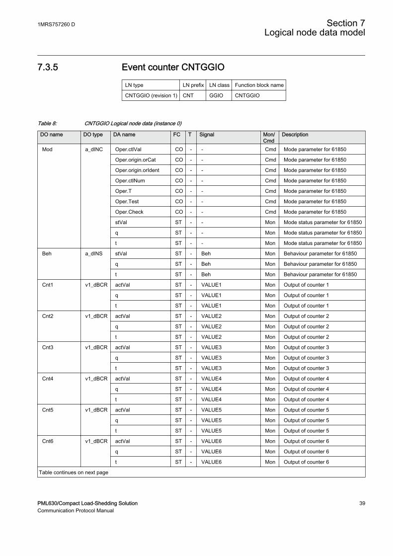
7.3.5 Event counter CNTGGIO
LN type LN prefix LN class Function block name
CNTGGIO (revision 1) CNT GGIO CNTGGIO
Table 8: CNTGGIO Logical node data (instance 0)
DO name DO type DA name FC T Signal Mon/Cmd
Description
Mod a_dINC Oper.ctlVal CO - - Cmd Mode parameter for 61850
Oper.origin.orCat CO - - Cmd Mode parameter for 61850
Oper.origin.orIdent CO - - Cmd Mode parameter for 61850
Oper.ctlNum CO - - Cmd Mode parameter for 61850
Oper.T CO - - Cmd Mode parameter for 61850
Oper.Test CO - - Cmd Mode parameter for 61850
Oper.Check CO - - Cmd Mode parameter for 61850
stVal ST - - Mon Mode status parameter for 61850
q ST - - Mon Mode status parameter for 61850
t ST - - Mon Mode status parameter for 61850
Beh a_dINS stVal ST - Beh Mon Behaviour parameter for 61850
q ST - Beh Mon Behaviour parameter for 61850
t ST - Beh Mon Behaviour parameter for 61850
Cnt1 v1_dBCR actVal ST - VALUE1 Mon Output of counter 1
q ST - VALUE1 Mon Output of counter 1
t ST - VALUE1 Mon Output of counter 1
Cnt2 v1_dBCR actVal ST - VALUE2 Mon Output of counter 2
q ST - VALUE2 Mon Output of counter 2
t ST - VALUE2 Mon Output of counter 2
Cnt3 v1_dBCR actVal ST - VALUE3 Mon Output of counter 3
q ST - VALUE3 Mon Output of counter 3
t ST - VALUE3 Mon Output of counter 3
Cnt4 v1_dBCR actVal ST - VALUE4 Mon Output of counter 4
q ST - VALUE4 Mon Output of counter 4
t ST - VALUE4 Mon Output of counter 4
Cnt5 v1_dBCR actVal ST - VALUE5 Mon Output of counter 5
q ST - VALUE5 Mon Output of counter 5
t ST - VALUE5 Mon Output of counter 5
Cnt6 v1_dBCR actVal ST - VALUE6 Mon Output of counter 6
q ST - VALUE6 Mon Output of counter 6
t ST - VALUE6 Mon Output of counter 6
Table continues on next page
1MRS757260 D Section 7Logical node data model
PML630/Compact Load-Shedding Solution 39Communication Protocol Manual
DO name DO type DA name FC T Signal Mon/Cmd
Description
RsCnt v1_dSPC Oper.ctlVal CO - - Cmd Command parameter forIEC61850
Oper.origin.orCat CO - - Cmd Command parameter forIEC61850
Oper.origin.orIdent CO - - Cmd Command parameter forIEC61850
Oper.ctlNum CO - - Cmd Command parameter forIEC61850
Oper.T CO - - Cmd Command parameter forIEC61850
Oper.Test CO - - Cmd Command parameter forIEC61850
Oper.Check CO - - Cmd Command parameter forIEC61850
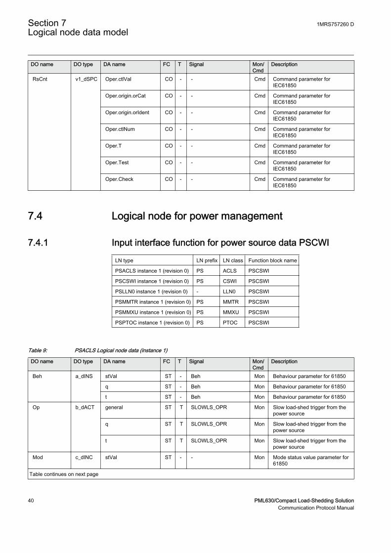
7.4 Logical node for power management
7.4.1 Input interface function for power source data PSCWI
LN type LN prefix LN class Function block name
PSACLS instance 1 (revision 0) PS ACLS PSCSWI
PSCSWI instance 1 (revision 0) PS CSWI PSCSWI
PSLLN0 instance 1 (revision 0) - LLN0 PSCSWI
PSMMTR instance 1 (revision 0) PS MMTR PSCSWI
PSMMXU instance 1 (revision 0) PS MMXU PSCSWI
PSPTOC instance 1 (revision 0) PS PTOC PSCSWI
Table 9: PSACLS Logical node data (instance 1)
DO name DO type DA name FC T Signal Mon/Cmd
Description
Beh a_dINS stVal ST - Beh Mon Behaviour parameter for 61850
q ST - Beh Mon Behaviour parameter for 61850
t ST - Beh Mon Behaviour parameter for 61850
Op b_dACT general ST T SLOWLS_OPR Mon Slow load-shed trigger from thepower source
q ST T SLOWLS_OPR Mon Slow load-shed trigger from thepower source
t ST T SLOWLS_OPR Mon Slow load-shed trigger from thepower source
Mod c_dINC stVal ST - - Mon Mode status value parameter for61850
Table continues on next page
Section 7 1MRS757260 DLogical node data model
40 PML630/Compact Load-Shedding SolutionCommunication Protocol Manual
DO name DO type DA name FC T Signal Mon/Cmd
Description
Mod c_dINC q ST - - Mon Mode status value parameter for61850
t ST - - Mon Mode status value parameter for61850
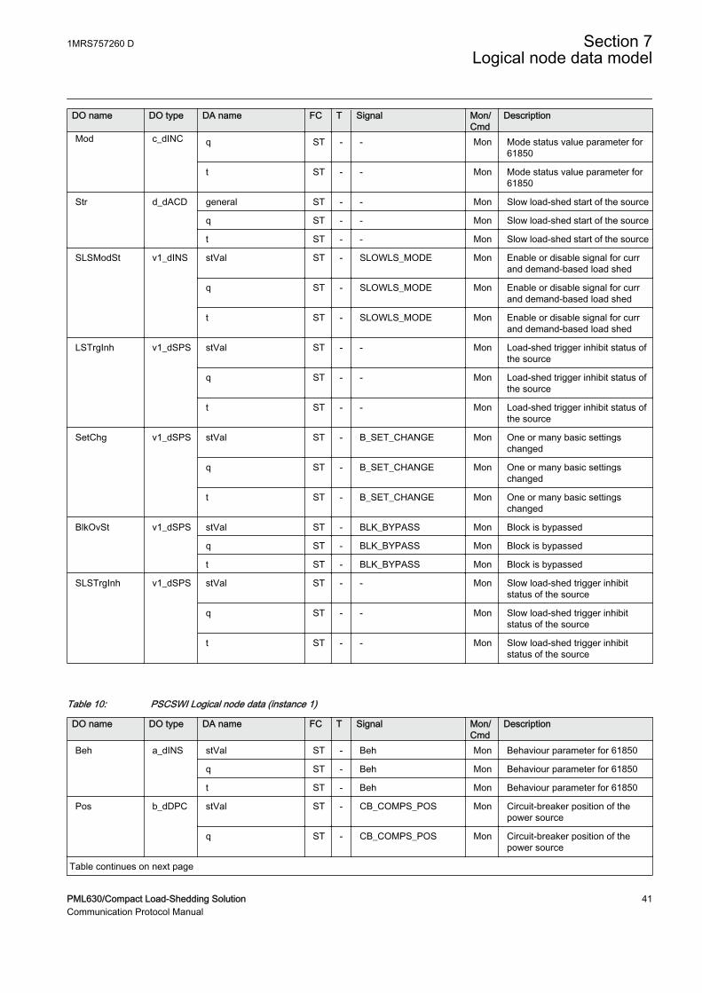
Str d_dACD general ST - - Mon Slow load-shed start of the source
q ST - - Mon Slow load-shed start of the source
t ST - - Mon Slow load-shed start of the source
SLSModSt v1_dINS stVal ST - SLOWLS_MODE Mon Enable or disable signal for currand demand-based load shed
q ST - SLOWLS_MODE Mon Enable or disable signal for currand demand-based load shed
t ST - SLOWLS_MODE Mon Enable or disable signal for currand demand-based load shed
LSTrgInh v1_dSPS stVal ST - - Mon Load-shed trigger inhibit status ofthe source
q ST - - Mon Load-shed trigger inhibit status ofthe source
t ST - - Mon Load-shed trigger inhibit status ofthe source
SetChg v1_dSPS stVal ST - B_SET_CHANGE Mon One or many basic settingschanged
q ST - B_SET_CHANGE Mon One or many basic settingschanged
t ST - B_SET_CHANGE Mon One or many basic settingschanged
BlkOvSt v1_dSPS stVal ST - BLK_BYPASS Mon Block is bypassed
q ST - BLK_BYPASS Mon Block is bypassed
t ST - BLK_BYPASS Mon Block is bypassed
SLSTrgInh v1_dSPS stVal ST - - Mon Slow load-shed trigger inhibitstatus of the source
q ST - - Mon Slow load-shed trigger inhibitstatus of the source
t ST - - Mon Slow load-shed trigger inhibitstatus of the source
Table 10: PSCSWI Logical node data (instance 1)
DO name DO type DA name FC T Signal Mon/Cmd
Description
Beh a_dINS stVal ST - Beh Mon Behaviour parameter for 61850
q ST - Beh Mon Behaviour parameter for 61850
t ST - Beh Mon Behaviour parameter for 61850
Pos b_dDPC stVal ST - CB_COMPS_POS Mon Circuit-breaker position of thepower source
q ST - CB_COMPS_POS Mon Circuit-breaker position of thepower source
Table continues on next page
1MRS757260 D Section 7Logical node data model
PML630/Compact Load-Shedding Solution 41Communication Protocol Manual
DO name DO type DA name FC T Signal Mon/Cmd
Description
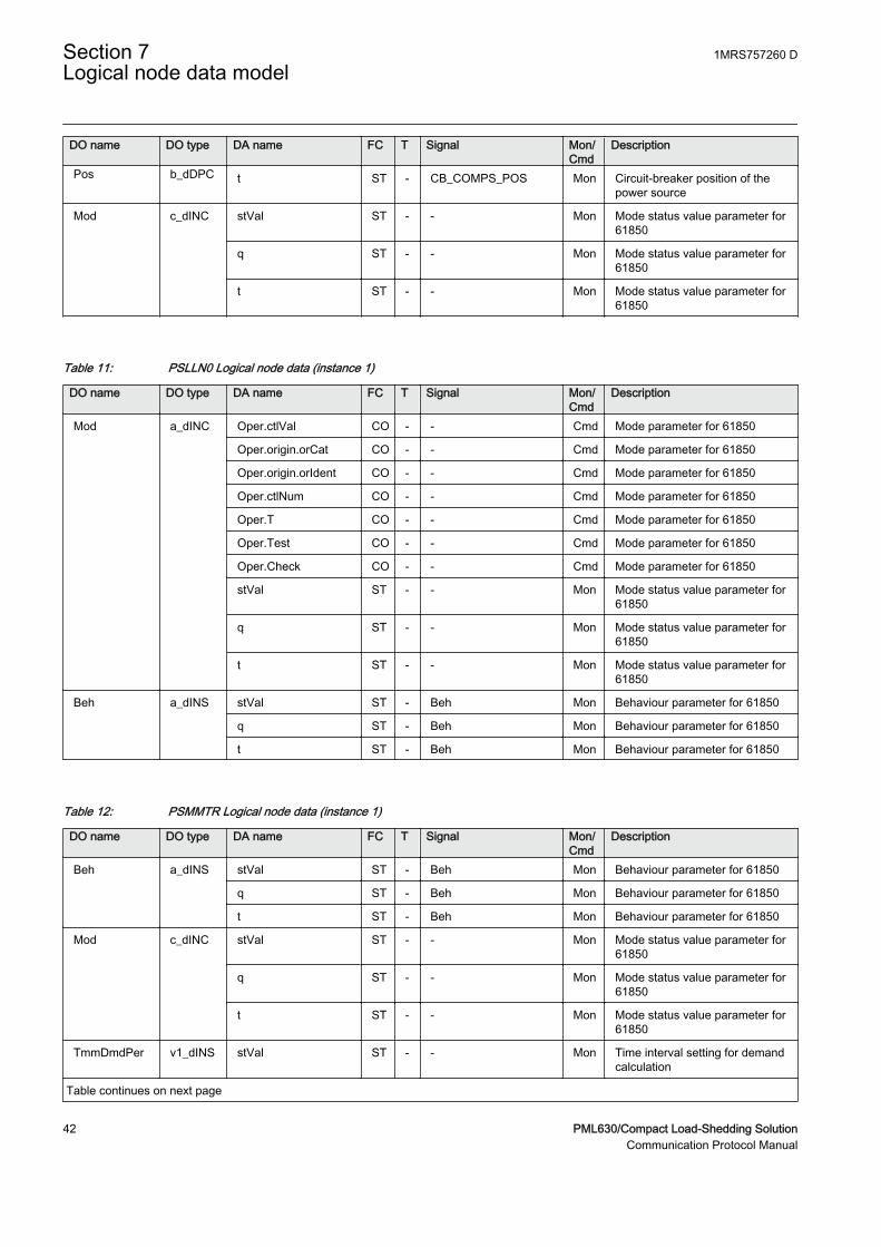
Pos b_dDPC t ST - CB_COMPS_POS Mon Circuit-breaker position of thepower source
Mod c_dINC stVal ST - - Mon Mode status value parameter for61850
q ST - - Mon Mode status value parameter for61850
t ST - - Mon Mode status value parameter for61850
Table 11: PSLLN0 Logical node data (instance 1)
DO name DO type DA name FC T Signal Mon/Cmd
Description
Mod a_dINC Oper.ctlVal CO - - Cmd Mode parameter for 61850
Oper.origin.orCat CO - - Cmd Mode parameter for 61850
Oper.origin.orIdent CO - - Cmd Mode parameter for 61850
Oper.ctlNum CO - - Cmd Mode parameter for 61850
Oper.T CO - - Cmd Mode parameter for 61850
Oper.Test CO - - Cmd Mode parameter for 61850
Oper.Check CO - - Cmd Mode parameter for 61850
stVal ST - - Mon Mode status value parameter for61850
q ST - - Mon Mode status value parameter for61850
t ST - - Mon Mode status value parameter for61850
Beh a_dINS stVal ST - Beh Mon Behaviour parameter for 61850
q ST - Beh Mon Behaviour parameter for 61850
t ST - Beh Mon Behaviour parameter for 61850
Table 12: PSMMTR Logical node data (instance 1)
DO name DO type DA name FC T Signal Mon/Cmd
Description
Beh a_dINS stVal ST - Beh Mon Behaviour parameter for 61850
q ST - Beh Mon Behaviour parameter for 61850
t ST - Beh Mon Behaviour parameter for 61850
Mod c_dINC stVal ST - - Mon Mode status value parameter for61850
q ST - - Mon Mode status value parameter for61850
t ST - - Mon Mode status value parameter for61850
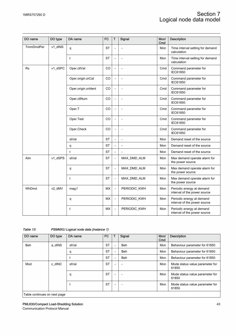
TmmDmdPer v1_dINS stVal ST - - Mon Time interval setting for demandcalculation
Table continues on next page
Section 7 1MRS757260 DLogical node data model
42 PML630/Compact Load-Shedding SolutionCommunication Protocol Manual
DO name DO type DA name FC T Signal Mon/Cmd
Description
TmmDmdPer v1_dINS q ST - - Mon Time interval setting for demandcalculation
t ST - - Mon Time interval setting for demandcalculation
Rs v1_dSPC Oper.ctlVal CO - - Cmd Command parameter forIEC61850
Oper.origin.orCat CO - - Cmd Command parameter forIEC61850
Oper.origin.orIdent CO - - Cmd Command parameter forIEC61850
Oper.ctlNum CO - - Cmd Command parameter forIEC61850
Oper.T CO - - Cmd Command parameter forIEC61850
Oper.Test CO - - Cmd Command parameter forIEC61850
Oper.Check CO - - Cmd Command parameter forIEC61850
stVal ST - - Mon Demand reset of the source
q ST - - Mon Demand reset of the source
t ST - - Mon Demand reset of the source
Alm v1_dSPS stVal ST - MAX_DMD_ALM Mon Max demand operate alarm forthe power source
q ST - MAX_DMD_ALM Mon Max demand operate alarm forthe power source
t ST - MAX_DMD_ALM Mon Max demand operate alarm forthe power source
WhDmd v2_dMV mag.f MX - PERIODIC_KWH Mon Periodic energy at demandinterval of the power source
q MX - PERIODIC_KWH Mon Periodic energy at demandinterval of the power source
t MX - PERIODIC_KWH Mon Periodic energy at demandinterval of the power source
Table 13: PSMMXU Logical node data (instance 1)
DO name DO type DA name FC T Signal Mon/Cmd
Description
Beh a_dINS stVal ST - Beh Mon Behaviour parameter for 61850
q ST - Beh Mon Behaviour parameter for 61850
t ST - Beh Mon Behaviour parameter for 61850
Mod c_dINC stVal ST - - Mon Mode status value parameter for61850
q ST - - Mon Mode status value parameter for61850
t ST - - Mon Mode status value parameter for61850
Table continues on next page
1MRS757260 D Section 7Logical node data model
PML630/Compact Load-Shedding Solution 43Communication Protocol Manual
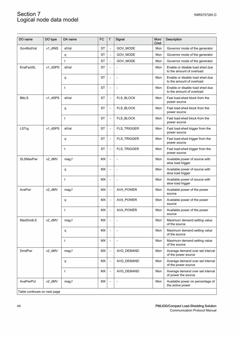
DO name DO type DA name FC T Signal Mon/Cmd
Description
GovModVal v1_dINS stVal ST - GOV_MODE Mon Governor mode of the generator
q ST - GOV_MODE Mon Governor mode of the generator
t ST - GOV_MODE Mon Governor mode of the generator
EnaFactSL v1_dSPS stVal ST - - Mon Enable or disable load shed dueto the amount of overload
q ST - - Mon Enable or disable load shed dueto the amount of overload
t ST - - Mon Enable or disable load shed dueto the amount of overload
BlkLS v1_dSPS stVal ST - FLS_BLOCK Mon Fast load-shed block from thepower source
q ST - FLS_BLOCK Mon Fast load-shed block from thepower source
t ST - FLS_BLOCK Mon Fast load-shed block from thepower source
LSTrg v1_dSPS stVal ST - FLS_TRIGGER Mon Fast load-shed trigger from thepower source
q ST - FLS_TRIGGER Mon Fast load-shed trigger from thepower source
t ST - FLS_TRIGGER Mon Fast load-shed trigger from thepower source
SLSMaxPwr v2_dMV mag.f MX - - Mon Available power of source withslow load trigger
q MX - - Mon Available power of source withslow load trigger
t MX - - Mon Available power of source withslow load trigger
AvaPwr v2_dMV mag.f MX - AVA_POWER Mon Available power of the powersource
q MX - AVA_POWER Mon Available power of the powersource
t MX - AVA_POWER Mon Available power of the powersource
MaxDmdLS v2_dMV mag.f MX - - Mon Maximum demand setting valueof the source
q MX - - Mon Maximum demand setting valueof the source
t MX - - Mon Maximum demand setting valueof the source
DmdPwr v2_dMV mag.f MX - AVG_DEMAND Mon Average demand over set intervalof the power source
q MX - AVG_DEMAND Mon Average demand over set intervalof the power source
t MX - AVG_DEMAND Mon Average demand over set intervalof power the source
AvaPwrPct v2_dMV mag.f MX - - Mon Available power on percentage ofthe active power
Table continues on next page
Section 7 1MRS757260 DLogical node data model
44 PML630/Compact Load-Shedding SolutionCommunication Protocol Manual
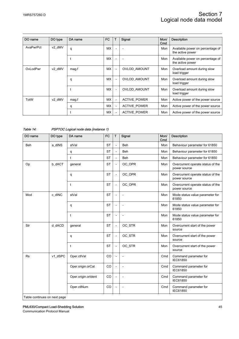
DO name DO type DA name FC T Signal Mon/Cmd
Description
AvaPwrPct v2_dMV q MX - - Mon Available power on percentage ofthe active power
t MX - - Mon Available power on percentage ofthe active power
OvLodPwr v2_dMV mag.f MX - OVLOD_AMOUNT Mon Overload amount during slowload trigger
q MX - OVLOD_AMOUNT Mon Overload amount during slowload trigger
t MX - OVLOD_AMOUNT Mon Overload amount during slowload trigger
TotW v2_dMV mag.f MX - ACTIVE_POWER Mon Active power of the power source
q MX - ACTIVE_POWER Mon Active power of the power source
t MX - ACTIVE_POWER Mon Active power of the power source
Table 14: PSPTOC Logical node data (instance 1)
DO name DO type DA name FC T Signal Mon/Cmd
Description
Beh a_dINS stVal ST - Beh Mon Behaviour parameter for 61850
q ST - Beh Mon Behaviour parameter for 61850
t ST - Beh Mon Behaviour parameter for 61850
Op b_dACT general ST - OC_OPR Mon Overcurrent operate status of thepower source
q ST - OC_OPR Mon Overcurrent operate status of thepower source
t ST - OC_OPR Mon Overcurrent operate status of thepower source
Mod c_dINC stVal ST - - Mon Mode status value parameter for61850
q ST - - Mon Mode status value parameter for61850
t ST - - Mon Mode status value parameter for61850
Str d_dACD general ST - OC_STR Mon Overcurrent start of the powersource
q ST - OC_STR Mon Overcurrent start of the powersource
t ST - OC_STR Mon Overcurrent start of the powersource
Rs v1_dSPC Oper.ctlVal CO - - Cmd Command parameter forIEC61850
Oper.origin.orCat CO - - Cmd Command parameter forIEC61850
Oper.origin.orIdent CO - - Cmd Command parameter forIEC61850
Oper.ctlNum CO - - Cmd Command parameter forIEC61850
Table continues on next page
1MRS757260 D Section 7Logical node data model
PML630/Compact Load-Shedding Solution 45Communication Protocol Manual
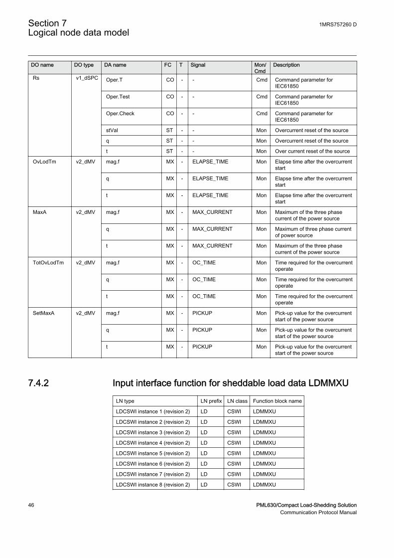
DO name DO type DA name FC T Signal Mon/Cmd
Description
Rs v1_dSPC Oper.T CO - - Cmd Command parameter forIEC61850
Oper.Test CO - - Cmd Command parameter forIEC61850
Oper.Check CO - - Cmd Command parameter forIEC61850
stVal ST - - Mon Overcurrent reset of the source
q ST - - Mon Overcurrent reset of the source
t ST - - Mon Over current reset of the source
OvLodTm v2_dMV mag.f MX - ELAPSE_TIME Mon Elapse time after the overcurrentstart
q MX - ELAPSE_TIME Mon Elapse time after the overcurrentstart
t MX - ELAPSE_TIME Mon Elapse time after the overcurrentstart
MaxA v2_dMV mag.f MX - MAX_CURRENT Mon Maximum of the three phasecurrent of the power source
q MX - MAX_CURRENT Mon Maximum of three phase currentof power source
t MX - MAX_CURRENT Mon Maximum of the three phasecurrent of the power source
TotOvLodTm v2_dMV mag.f MX - OC_TIME Mon Time required for the overcurrentoperate
q MX - OC_TIME Mon Time required for the overcurrentoperate
t MX - OC_TIME Mon Time required for the overcurrentoperate
SetMaxA v2_dMV mag.f MX - PICKUP Mon Pick-up value for the overcurrentstart of the power source
q MX - PICKUP Mon Pick-up value for the overcurrentstart of the power source
t MX - PICKUP Mon Pick-up value for the overcurrentstart of the power source
7.4.2 Input interface function for sheddable load data LDMMXU
LN type LN prefix LN class Function block name
LDCSWI instance 1 (revision 2) LD CSWI LDMMXU
LDCSWI instance 2 (revision 2) LD CSWI LDMMXU
LDCSWI instance 3 (revision 2) LD CSWI LDMMXU
LDCSWI instance 4 (revision 2) LD CSWI LDMMXU
LDCSWI instance 5 (revision 2) LD CSWI LDMMXU
LDCSWI instance 6 (revision 2) LD CSWI LDMMXU
LDCSWI instance 7 (revision 2) LD CSWI LDMMXU
LDCSWI instance 8 (revision 2) LD CSWI LDMMXU
Section 7 1MRS757260 DLogical node data model
46 PML630/Compact Load-Shedding SolutionCommunication Protocol Manual

LDCSWI instance 9 (revision 2) LD CSWI LDMMXU
LDCSWI instance 10 (revision 2) LD CSWI LDMMXU
LDGGIO instance 1 (revision 1) LD GGIO LDMMXU
LDLLN0 instance 1 (revision 1) - LLN0 LDMMXU
LDMMXU instance 1 (revision 2) LD MMXU LDMMXU
LDMMXU instance 2 (revision 2) LD MMXU LDMMXU
LDMMXU instance 3 (revision 2) LD MMXU LDMMXU
LDMMXU instance 4 (revision 2) LD MMXU LDMMXU
LDMMXU instance 5 (revision 2) LD MMXU LDMMXU
LDMMXU instance 6 (revision 2) LD MMXU LDMMXU
LDMMXU instance 7 (revision 2) LD MMXU LDMMXU
LDMMXU instance 8 (revision 2) LD MMXU LDMMXU
LDMMXU instance 9 (revision 2) LD MMXU LDMMXU
LDMMXU instance 10 (revision 2) LD MMXU LDMMXU
Table 15: LDCSWI Logical node data (instance 1)
DO name DO type DA name FC T Signal Mon/Cmd
Description
Beh a_dINS stVal ST - Beh Mon Behaviour parameter for 61850
q ST - Beh Mon Behaviour parameter for 61850
t ST - Beh Mon Behaviour parameter for 61850
Pos b_dDPC stVal ST - L1_CB_COMPS Mon Circuit-breaker position of thesheddable load1
q ST - L1_CB_COMPS Mon Circuit-breaker position of thesheddable load1
t ST - L1_CB_COMPS Mon Circuit-breaker position of thesheddable load1
Mod c_dINC stVal ST - - Mon Mode status value parameter for61850
q ST - - Mon Mode status value parameter for61850
t ST - - Mon Mode status value parameter for61850
Table 16: LDCSWI Logical node data (instance 2)
DO name DO type DA name FC T Signal Mon/Cmd
Description
Beh a_dINS stVal ST - Beh Mon Behaviour parameter for 61850
q ST - Beh Mon Behaviour parameter for 61850
t ST - Beh Mon Behaviour parameter for 61850
Pos b_dDPC stVal ST - L2_CB_COMPS Mon Circuit-breaker position of thesheddable load2
Table continues on next page
1MRS757260 D Section 7Logical node data model
PML630/Compact Load-Shedding Solution 47Communication Protocol Manual
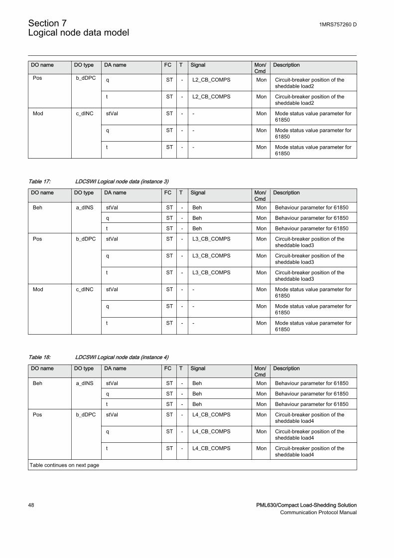
DO name DO type DA name FC T Signal Mon/Cmd
Description
Pos b_dDPC q ST - L2_CB_COMPS Mon Circuit-breaker position of thesheddable load2
t ST - L2_CB_COMPS Mon Circuit-breaker position of thesheddable load2
Mod c_dINC stVal ST - - Mon Mode status value parameter for61850
q ST - - Mon Mode status value parameter for61850
t ST - - Mon Mode status value parameter for61850
Table 17: LDCSWI Logical node data (instance 3)
DO name DO type DA name FC T Signal Mon/Cmd
Description
Beh a_dINS stVal ST - Beh Mon Behaviour parameter for 61850
q ST - Beh Mon Behaviour parameter for 61850
t ST - Beh Mon Behaviour parameter for 61850
Pos b_dDPC stVal ST - L3_CB_COMPS Mon Circuit-breaker position of thesheddable load3
q ST - L3_CB_COMPS Mon Circuit-breaker position of thesheddable load3
t ST - L3_CB_COMPS Mon Circuit-breaker position of thesheddable load3
Mod c_dINC stVal ST - - Mon Mode status value parameter for61850
q ST - - Mon Mode status value parameter for61850
t ST - - Mon Mode status value parameter for61850
Table 18: LDCSWI Logical node data (instance 4)
DO name DO type DA name FC T Signal Mon/Cmd
Description
Beh a_dINS stVal ST - Beh Mon Behaviour parameter for 61850
q ST - Beh Mon Behaviour parameter for 61850
t ST - Beh Mon Behaviour parameter for 61850
Pos b_dDPC stVal ST - L4_CB_COMPS Mon Circuit-breaker position of thesheddable load4
q ST - L4_CB_COMPS Mon Circuit-breaker position of thesheddable load4
t ST - L4_CB_COMPS Mon Circuit-breaker position of thesheddable load4
Table continues on next page
Section 7 1MRS757260 DLogical node data model
48 PML630/Compact Load-Shedding SolutionCommunication Protocol Manual
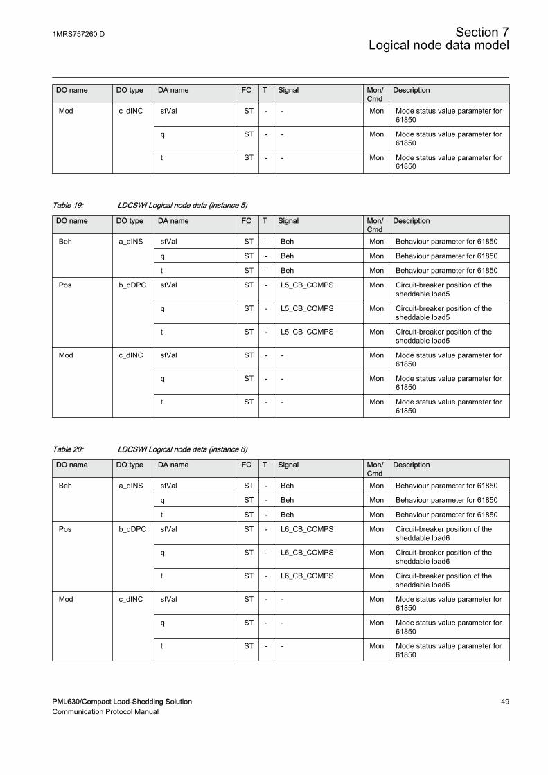
DO name DO type DA name FC T Signal Mon/Cmd
Description
Mod c_dINC stVal ST - - Mon Mode status value parameter for61850
q ST - - Mon Mode status value parameter for61850
t ST - - Mon Mode status value parameter for61850
Table 19: LDCSWI Logical node data (instance 5)
DO name DO type DA name FC T Signal Mon/Cmd
Description
Beh a_dINS stVal ST - Beh Mon Behaviour parameter for 61850
q ST - Beh Mon Behaviour parameter for 61850
t ST - Beh Mon Behaviour parameter for 61850
Pos b_dDPC stVal ST - L5_CB_COMPS Mon Circuit-breaker position of thesheddable load5
q ST - L5_CB_COMPS Mon Circuit-breaker position of thesheddable load5
t ST - L5_CB_COMPS Mon Circuit-breaker position of thesheddable load5
Mod c_dINC stVal ST - - Mon Mode status value parameter for61850
q ST - - Mon Mode status value parameter for61850
t ST - - Mon Mode status value parameter for61850
Table 20: LDCSWI Logical node data (instance 6)
DO name DO type DA name FC T Signal Mon/Cmd
Description
Beh a_dINS stVal ST - Beh Mon Behaviour parameter for 61850
q ST - Beh Mon Behaviour parameter for 61850
t ST - Beh Mon Behaviour parameter for 61850
Pos b_dDPC stVal ST - L6_CB_COMPS Mon Circuit-breaker position of thesheddable load6
q ST - L6_CB_COMPS Mon Circuit-breaker position of thesheddable load6
t ST - L6_CB_COMPS Mon Circuit-breaker position of thesheddable load6
Mod c_dINC stVal ST - - Mon Mode status value parameter for61850
q ST - - Mon Mode status value parameter for61850
t ST - - Mon Mode status value parameter for61850
1MRS757260 D Section 7Logical node data model
PML630/Compact Load-Shedding Solution 49Communication Protocol Manual
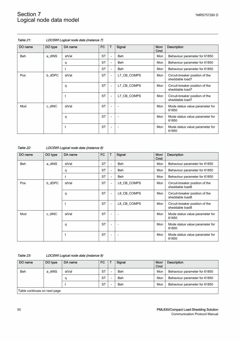
Table 21: LDCSWI Logical node data (instance 7)
DO name DO type DA name FC T Signal Mon/Cmd
Description
Beh a_dINS stVal ST - Beh Mon Behaviour parameter for 61850
q ST - Beh Mon Behaviour parameter for 61850
t ST - Beh Mon Behaviour parameter for 61850
Pos b_dDPC stVal ST - L7_CB_COMPS Mon Circuit-breaker position of thesheddable load7
q ST - L7_CB_COMPS Mon Circuit-breaker position of thesheddable load7
t ST - L7_CB_COMPS Mon Circuit-breaker position of thesheddable load7
Mod c_dINC stVal ST - - Mon Mode status value parameter for61850
q ST - - Mon Mode status value parameter for61850
t ST - - Mon Mode status value parameter for61850
Table 22: LDCSWI Logical node data (instance 8)
DO name DO type DA name FC T Signal Mon/Cmd
Description
Beh a_dINS stVal ST - Beh Mon Behaviour parameter for 61850
q ST - Beh Mon Behaviour parameter for 61850
t ST - Beh Mon Behaviour parameter for 61850
Pos b_dDPC stVal ST - L8_CB_COMPS Mon Circuit-breaker position of thesheddable load8
q ST - L8_CB_COMPS Mon Circuit-breaker position of thesheddable load8
t ST - L8_CB_COMPS Mon Circuit-breaker position of thesheddable load8
Mod c_dINC stVal ST - - Mon Mode status value parameter for61850
q ST - - Mon Mode status value parameter for61850
t ST - - Mon Mode status value parameter for61850
Table 23: LDCSWI Logical node data (instance 9)
DO name DO type DA name FC T Signal Mon/Cmd
Description
Beh a_dINS stVal ST - Beh Mon Behaviour parameter for 61850
q ST - Beh Mon Behaviour parameter for 61850
t ST - Beh Mon Behaviour parameter for 61850
Table continues on next page
Section 7 1MRS757260 DLogical node data model
50 PML630/Compact Load-Shedding SolutionCommunication Protocol Manual
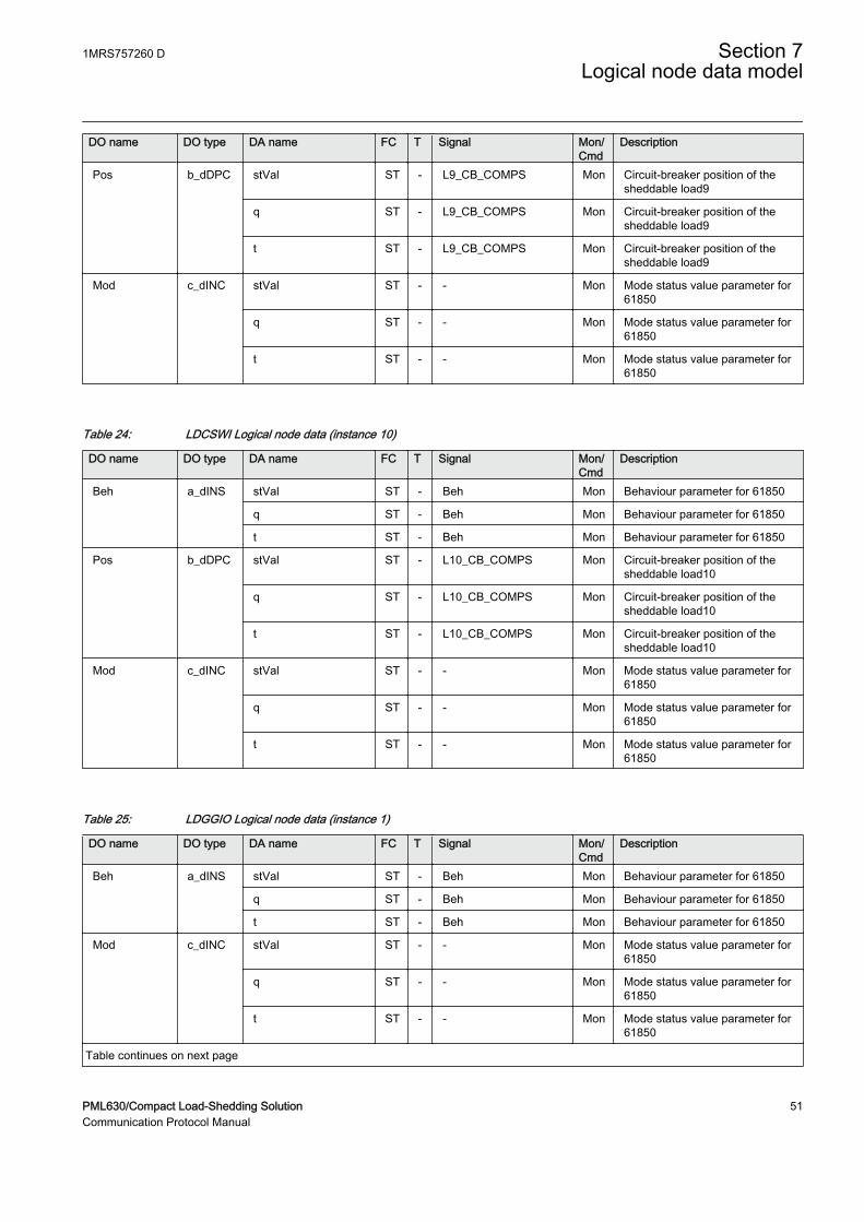
DO name DO type DA name FC T Signal Mon/Cmd
Description
Pos b_dDPC stVal ST - L9_CB_COMPS Mon Circuit-breaker position of thesheddable load9
q ST - L9_CB_COMPS Mon Circuit-breaker position of thesheddable load9
t ST - L9_CB_COMPS Mon Circuit-breaker position of thesheddable load9
Mod c_dINC stVal ST - - Mon Mode status value parameter for61850
q ST - - Mon Mode status value parameter for61850
t ST - - Mon Mode status value parameter for61850
Table 24: LDCSWI Logical node data (instance 10)
DO name DO type DA name FC T Signal Mon/Cmd
Description
Beh a_dINS stVal ST - Beh Mon Behaviour parameter for 61850
q ST - Beh Mon Behaviour parameter for 61850
t ST - Beh Mon Behaviour parameter for 61850
Pos b_dDPC stVal ST - L10_CB_COMPS Mon Circuit-breaker position of thesheddable load10
q ST - L10_CB_COMPS Mon Circuit-breaker position of thesheddable load10
t ST - L10_CB_COMPS Mon Circuit-breaker position of thesheddable load10
Mod c_dINC stVal ST - - Mon Mode status value parameter for61850
q ST - - Mon Mode status value parameter for61850
t ST - - Mon Mode status value parameter for61850
Table 25: LDGGIO Logical node data (instance 1)
DO name DO type DA name FC T Signal Mon/Cmd
Description
Beh a_dINS stVal ST - Beh Mon Behaviour parameter for 61850
q ST - Beh Mon Behaviour parameter for 61850
t ST - Beh Mon Behaviour parameter for 61850
Mod c_dINC stVal ST - - Mon Mode status value parameter for61850
q ST - - Mon Mode status value parameter for61850
t ST - - Mon Mode status value parameter for61850
Table continues on next page
1MRS757260 D Section 7Logical node data model
PML630/Compact Load-Shedding Solution 51Communication Protocol Manual
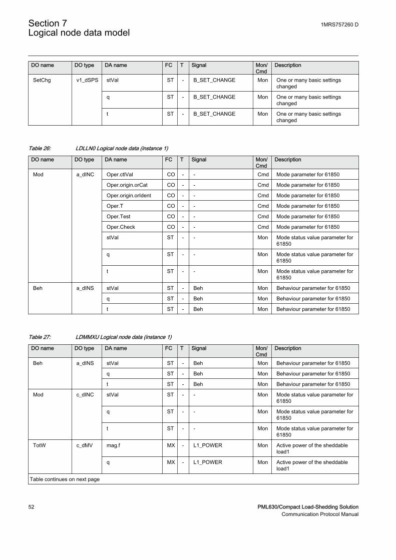
DO name DO type DA name FC T Signal Mon/Cmd
Description
SetChg v1_dSPS stVal ST - B_SET_CHANGE Mon One or many basic settingschanged
q ST - B_SET_CHANGE Mon One or many basic settingschanged
t ST - B_SET_CHANGE Mon One or many basic settingschanged
Table 26: LDLLN0 Logical node data (instance 1)
DO name DO type DA name FC T Signal Mon/Cmd
Description
Mod a_dINC Oper.ctlVal CO - - Cmd Mode parameter for 61850
Oper.origin.orCat CO - - Cmd Mode parameter for 61850
Oper.origin.orIdent CO - - Cmd Mode parameter for 61850
Oper.T CO - - Cmd Mode parameter for 61850
Oper.Test CO - - Cmd Mode parameter for 61850
Oper.Check CO - - Cmd Mode parameter for 61850
stVal ST - - Mon Mode status value parameter for61850
q ST - - Mon Mode status value parameter for61850
t ST - - Mon Mode status value parameter for61850
Beh a_dINS stVal ST - Beh Mon Behaviour parameter for 61850
q ST - Beh Mon Behaviour parameter for 61850
t ST - Beh Mon Behaviour parameter for 61850
Table 27: LDMMXU Logical node data (instance 1)
DO name DO type DA name FC T Signal Mon/Cmd
Description
Beh a_dINS stVal ST - Beh Mon Behaviour parameter for 61850
q ST - Beh Mon Behaviour parameter for 61850
t ST - Beh Mon Behaviour parameter for 61850
Mod c_dINC stVal ST - - Mon Mode status value parameter for61850
q ST - - Mon Mode status value parameter for61850
t ST - - Mon Mode status value parameter for61850
TotW c_dMV mag.f MX - L1_POWER Mon Active power of the sheddableload1
q MX - L1_POWER Mon Active power of the sheddableload1
Table continues on next page
Section 7 1MRS757260 DLogical node data model
52 PML630/Compact Load-Shedding SolutionCommunication Protocol Manual
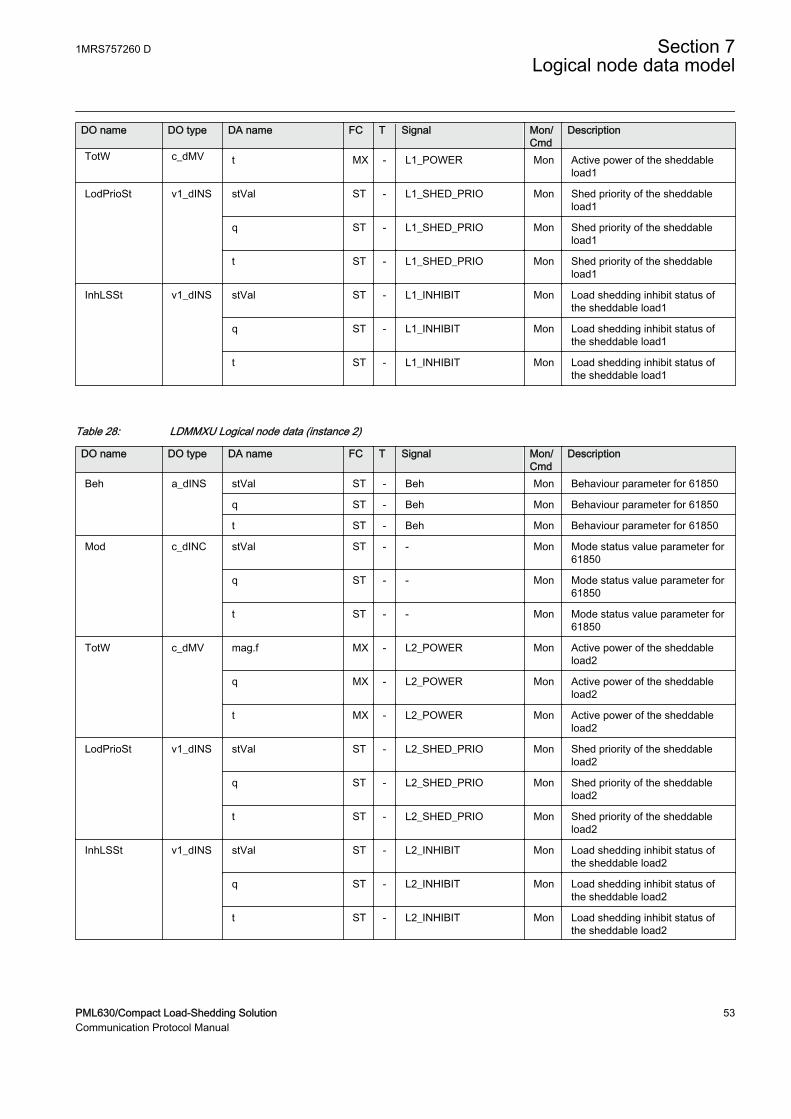
DO name DO type DA name FC T Signal Mon/Cmd
Description
TotW c_dMV t MX - L1_POWER Mon Active power of the sheddableload1
LodPrioSt v1_dINS stVal ST - L1_SHED_PRIO Mon Shed priority of the sheddableload1
q ST - L1_SHED_PRIO Mon Shed priority of the sheddableload1
t ST - L1_SHED_PRIO Mon Shed priority of the sheddableload1
InhLSSt v1_dINS stVal ST - L1_INHIBIT Mon Load shedding inhibit status ofthe sheddable load1
q ST - L1_INHIBIT Mon Load shedding inhibit status ofthe sheddable load1
t ST - L1_INHIBIT Mon Load shedding inhibit status ofthe sheddable load1
Table 28: LDMMXU Logical node data (instance 2)
DO name DO type DA name FC T Signal Mon/Cmd
Description
Beh a_dINS stVal ST - Beh Mon Behaviour parameter for 61850
q ST - Beh Mon Behaviour parameter for 61850
t ST - Beh Mon Behaviour parameter for 61850
Mod c_dINC stVal ST - - Mon Mode status value parameter for61850
q ST - - Mon Mode status value parameter for61850
t ST - - Mon Mode status value parameter for61850
TotW c_dMV mag.f MX - L2_POWER Mon Active power of the sheddableload2
q MX - L2_POWER Mon Active power of the sheddableload2
t MX - L2_POWER Mon Active power of the sheddableload2
LodPrioSt v1_dINS stVal ST - L2_SHED_PRIO Mon Shed priority of the sheddableload2
q ST - L2_SHED_PRIO Mon Shed priority of the sheddableload2
t ST - L2_SHED_PRIO Mon Shed priority of the sheddableload2
InhLSSt v1_dINS stVal ST - L2_INHIBIT Mon Load shedding inhibit status ofthe sheddable load2
q ST - L2_INHIBIT Mon Load shedding inhibit status ofthe sheddable load2
t ST - L2_INHIBIT Mon Load shedding inhibit status ofthe sheddable load2
1MRS757260 D Section 7Logical node data model
PML630/Compact Load-Shedding Solution 53Communication Protocol Manual
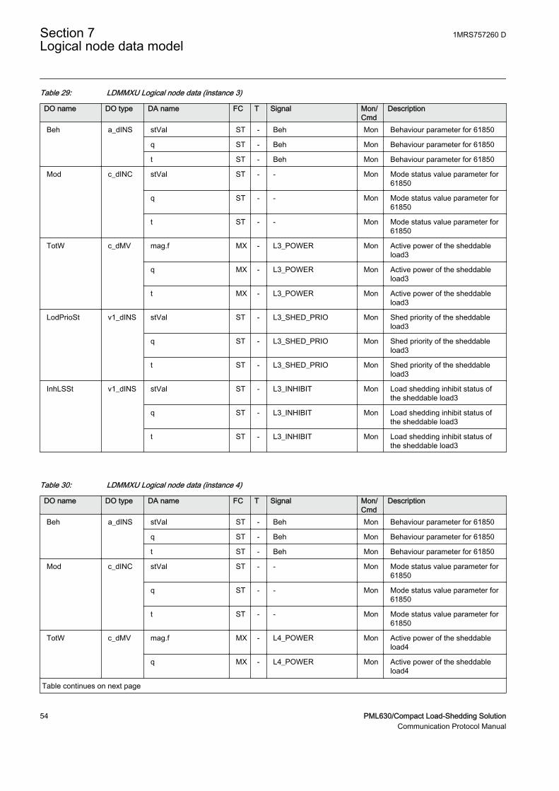
Table 29: LDMMXU Logical node data (instance 3)
DO name DO type DA name FC T Signal Mon/Cmd
Description
Beh a_dINS stVal ST - Beh Mon Behaviour parameter for 61850
q ST - Beh Mon Behaviour parameter for 61850
t ST - Beh Mon Behaviour parameter for 61850
Mod c_dINC stVal ST - - Mon Mode status value parameter for61850
q ST - - Mon Mode status value parameter for61850
t ST - - Mon Mode status value parameter for61850
TotW c_dMV mag.f MX - L3_POWER Mon Active power of the sheddableload3
q MX - L3_POWER Mon Active power of the sheddableload3
t MX - L3_POWER Mon Active power of the sheddableload3
LodPrioSt v1_dINS stVal ST - L3_SHED_PRIO Mon Shed priority of the sheddableload3
q ST - L3_SHED_PRIO Mon Shed priority of the sheddableload3
t ST - L3_SHED_PRIO Mon Shed priority of the sheddableload3
InhLSSt v1_dINS stVal ST - L3_INHIBIT Mon Load shedding inhibit status ofthe sheddable load3
q ST - L3_INHIBIT Mon Load shedding inhibit status ofthe sheddable load3
t ST - L3_INHIBIT Mon Load shedding inhibit status ofthe sheddable load3
Table 30: LDMMXU Logical node data (instance 4)
DO name DO type DA name FC T Signal Mon/Cmd
Description
Beh a_dINS stVal ST - Beh Mon Behaviour parameter for 61850
q ST - Beh Mon Behaviour parameter for 61850
t ST - Beh Mon Behaviour parameter for 61850
Mod c_dINC stVal ST - - Mon Mode status value parameter for61850
q ST - - Mon Mode status value parameter for61850
t ST - - Mon Mode status value parameter for61850
TotW c_dMV mag.f MX - L4_POWER Mon Active power of the sheddableload4
q MX - L4_POWER Mon Active power of the sheddableload4
Table continues on next page
Section 7 1MRS757260 DLogical node data model
54 PML630/Compact Load-Shedding SolutionCommunication Protocol Manual

DO name DO type DA name FC T Signal Mon/Cmd
Description
TotW c_dMV t MX - L4_POWER Mon Active power of the sheddableload4
LodPrioSt v1_dINS stVal ST - L4_SHED_PRIO Mon Shed priority of the sheddableload4
q ST - L4_SHED_PRIO Mon Shed priority of the sheddableload4
t ST - L4_SHED_PRIO Mon Shed priority of the sheddableload4
InhLSSt v1_dINS stVal ST - L4_INHIBIT Mon Load shedding inhibit status ofthe sheddable load4
q ST - L4_INHIBIT Mon Load shedding inhibit status ofthe sheddable load4
t ST - L4_INHIBIT Mon Load shedding inhibit status ofthe sheddable load4
Table 31: LDMMXU Logical node data (instance 5)
DO name DO type DA name FC T Signal Mon/Cmd
Description
Beh a_dINS stVal ST - Beh Mon Behaviour parameter for 61850
q ST - Beh Mon Behaviour parameter for 61850
t ST - Beh Mon Behaviour parameter for 61850
Mod c_dINC stVal ST - - Mon Mode status value parameter for61850
q ST - - Mon Mode status value parameter for61850
t ST - - Mon Mode status value parameter for61850
TotW c_dMV mag.f MX - L5_POWER Mon Active power of the sheddableload5
q MX - L5_POWER Mon Active power of the sheddableload5
t MX - L5_POWER Mon Active power of the sheddableload5
LodPrioSt v1_dINS stVal ST - L5_SHED_PRIO Mon Shed priority of the sheddableload5
q ST - L5_SHED_PRIO Mon Shed priority of the sheddableload5
t ST - L5_SHED_PRIO Mon Shed priority of the sheddableload5
InhLSSt v1_dINS stVal ST - L5_INHIBIT Mon Load shedding inhibit status ofthe sheddable load5
q ST - L5_INHIBIT Mon Load shedding inhibit status ofthe sheddable load5
t ST - L5_INHIBIT Mon Load shedding inhibit status ofthe sheddable load5
1MRS757260 D Section 7Logical node data model
PML630/Compact Load-Shedding Solution 55Communication Protocol Manual

Table 32: LDMMXU Logical node data (instance 6)
DO name DO type DA name FC T Signal Mon/Cmd
Description
Beh a_dINS stVal ST - Beh Mon Behaviour parameter for 61850
q ST - Beh Mon Behaviour parameter for 61850
t ST - Beh Mon Behaviour parameter for 61850
Mod c_dINC stVal ST - - Mon Mode status value parameter for61850
q ST - - Mon Mode status value parameter for61850
t ST - - Mon Mode status value parameter for61850
TotW c_dMV mag.f MX - L6_POWER Mon Active power of the sheddableload6
q MX - L6_POWER Mon Active power of the sheddableload6
t MX - L6_POWER Mon Active power of the sheddableload6
LodPrioSt v1_dINS stVal ST - L6_SHED_PRIO Mon Shed priority of the sheddableload6
q ST - L6_SHED_PRIO Mon Shed priority of the sheddableload6
t ST - L6_SHED_PRIO Mon Shed priority of the sheddableload6
InhLSSt v1_dINS stVal ST - L6_INHIBIT Mon Load shedding inhibit status ofthe sheddable load6
q ST - L6_INHIBIT Mon Load shedding inhibit status ofthe sheddable load6
t ST - L6_INHIBIT Mon Load shedding inhibit status ofthe sheddable load6
Table 33: LDMMXU Logical node data (instance 7)
DO name DO type DA name FC T Signal Mon/Cmd
Description
Beh a_dINS stVal ST - Beh Mon Behaviour parameter for 61850
q ST - Beh Mon Behaviour parameter for 61850
t ST - Beh Mon Behaviour parameter for 61850
Mod c_dINC stVal ST - - Mon Mode status value parameter for61850
q ST - - Mon Mode status value parameter for61850
t ST - - Mon Mode status value parameter for61850
TotW c_dMV mag.f MX - L7_POWER Mon Active power of the sheddableload7
q MX - L7_POWER Mon Active power of the sheddableload7
Table continues on next page
Section 7 1MRS757260 DLogical node data model
56 PML630/Compact Load-Shedding SolutionCommunication Protocol Manual

DO name DO type DA name FC T Signal Mon/Cmd
Description
TotW c_dMV t MX - L7_POWER Mon Active power of the sheddableload7
LodPrioSt v1_dINS stVal ST - L7_SHED_PRIO Mon Shed priority of the sheddableload7
q ST - L7_SHED_PRIO Mon Shed priority of the sheddableload7
t ST - L7_SHED_PRIO Mon Shed priority of the sheddableload7
InhLSSt v1_dINS stVal ST - L7_INHIBIT Mon Load shedding inhibit status ofthe sheddable load7
q ST - L7_INHIBIT Mon Load shedding inhibit status ofthe sheddable load7
t ST - L7_INHIBIT Mon Load shedding inhibit status ofthe sheddable load7
Table 34: LDMMXU Logical node data (instance 8)
DO name DO type DA name FC T Signal Mon/Cmd
Description
Beh a_dINS stVal ST - Beh Mon Behaviour parameter for 61850
q ST - Beh Mon Behaviour parameter for 61850
t ST - Beh Mon Behaviour parameter for 61850
Mod c_dINC stVal ST - - Mon Mode status value parameter for61850
q ST - - Mon Mode status value parameter for61850
t ST - - Mon Mode status value parameter for61850
TotW c_dMV mag.f MX - L8_POWER Mon Active power of the sheddableload8
q MX - L8_POWER Mon Active power of the sheddableload8
t MX - L8_POWER Mon Active power of the sheddableload8
LodPrioSt v1_dINS stVal ST - L8_SHED_PRIO Mon Shed priority of the sheddableload8
q ST - L8_SHED_PRIO Mon Shed priority of the sheddableload8
t ST - L8_SHED_PRIO Mon Shed priority of the sheddableload8
InhLSSt v1_dINS stVal ST - L8_INHIBIT Mon Load shedding inhibit status ofthe sheddable load8
q ST - L8_INHIBIT Mon Load shedding inhibit status ofthe sheddable load8
t ST - L8_INHIBIT Mon Load shedding inhibit status ofthe sheddable load8
1MRS757260 D Section 7Logical node data model
PML630/Compact Load-Shedding Solution 57Communication Protocol Manual

Table 35: LDMMXU Logical node data (instance 9)
DO name DO type DA name FC T Signal Mon/Cmd
Description
Beh a_dINS stVal ST - Beh Mon Behaviour parameter for 61850
q ST - Beh Mon Behaviour parameter for 61850
t ST - Beh Mon Behaviour parameter for 61850
Mod c_dINC stVal ST - - Mon Mode status value parameter for61850
q ST - - Mon Mode status value parameter for61850
t ST - - Mon Mode status value parameter for61850
TotW c_dMV mag.f MX - L9_POWER Mon Active power of the sheddableload9
q MX - L9_POWER Mon Active power of the sheddableload9
t MX - L9_POWER Mon Active power of the sheddableload9
LodPrioSt v1_dINS stVal ST - L9_SHED_PRIO Mon Shed priority of the sheddableload9
q ST - L9_SHED_PRIO Mon Shed priority of the sheddableload9
t ST - L9_SHED_PRIO Mon Shed priority of the sheddableload9
InhLSSt v1_dINS stVal ST - L9_INHIBIT Mon Load shedding inhibit status ofthe sheddable load9
q ST - L9_INHIBIT Mon Load shedding inhibit status ofthe sheddable load9
t ST - L9_INHIBIT Mon Load shedding inhibit status ofthe sheddable load9
Table 36: LDMMXU Logical node data (instance 10)
DO name DO type DA name FC T Signal Mon/Cmd
Description
Beh a_dINS stVal ST - Beh Mon Behaviour parameter for 61850
q ST - Beh Mon Behaviour parameter for 61850
t ST - Beh Mon Behaviour parameter for 61850
Mod c_dINC stVal ST - - Mon Mode status value parameter for61850
q ST - - Mon Mode status value parameter for61850
t ST - - Mon Mode status value parameter for61850
TotW c_dMV mag.f MX - L10_POWER Mon Active power of the sheddableload10
q MX - L10_POWER Mon Active power of the sheddableload10
Table continues on next page
Section 7 1MRS757260 DLogical node data model
58 PML630/Compact Load-Shedding SolutionCommunication Protocol Manual
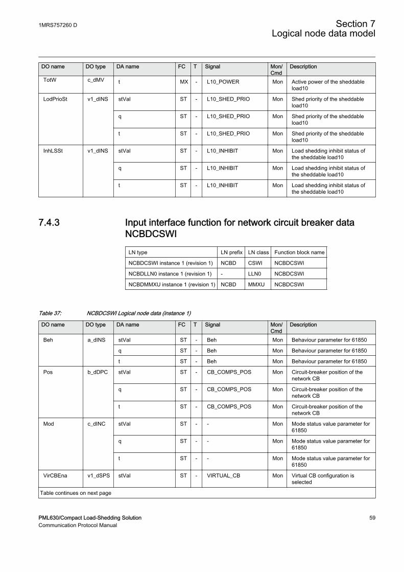
DO name DO type DA name FC T Signal Mon/Cmd
Description
TotW c_dMV t MX - L10_POWER Mon Active power of the sheddableload10
LodPrioSt v1_dINS stVal ST - L10_SHED_PRIO Mon Shed priority of the sheddableload10
q ST - L10_SHED_PRIO Mon Shed priority of the sheddableload10
t ST - L10_SHED_PRIO Mon Shed priority of the sheddableload10
InhLSSt v1_dINS stVal ST - L10_INHIBIT Mon Load shedding inhibit status ofthe sheddable load10
q ST - L10_INHIBIT Mon Load shedding inhibit status ofthe sheddable load10
t ST - L10_INHIBIT Mon Load shedding inhibit status ofthe sheddable load10
7.4.3 Input interface function for network circuit breaker dataNCBDCSWI
LN type LN prefix LN class Function block name
NCBDCSWI instance 1 (revision 1) NCBD CSWI NCBDCSWI
NCBDLLN0 instance 1 (revision 1) - LLN0 NCBDCSWI
NCBDMMXU instance 1 (revision 1) NCBD MMXU NCBDCSWI
Table 37: NCBDCSWI Logical node data (instance 1)
DO name DO type DA name FC T Signal Mon/Cmd
Description
Beh a_dINS stVal ST - Beh Mon Behaviour parameter for 61850
q ST - Beh Mon Behaviour parameter for 61850
t ST - Beh Mon Behaviour parameter for 61850
Pos b_dDPC stVal ST - CB_COMPS_POS Mon Circuit-breaker position of thenetwork CB
q ST - CB_COMPS_POS Mon Circuit-breaker position of thenetwork CB
t ST - CB_COMPS_POS Mon Circuit-breaker position of thenetwork CB
Mod c_dINC stVal ST - - Mon Mode status value parameter for61850
q ST - - Mon Mode status value parameter for61850
t ST - - Mon Mode status value parameter for61850
VirCBEna v1_dSPS stVal ST - VIRTUAL_CB Mon Virtual CB configuration isselected
Table continues on next page
1MRS757260 D Section 7Logical node data model
PML630/Compact Load-Shedding Solution 59Communication Protocol Manual
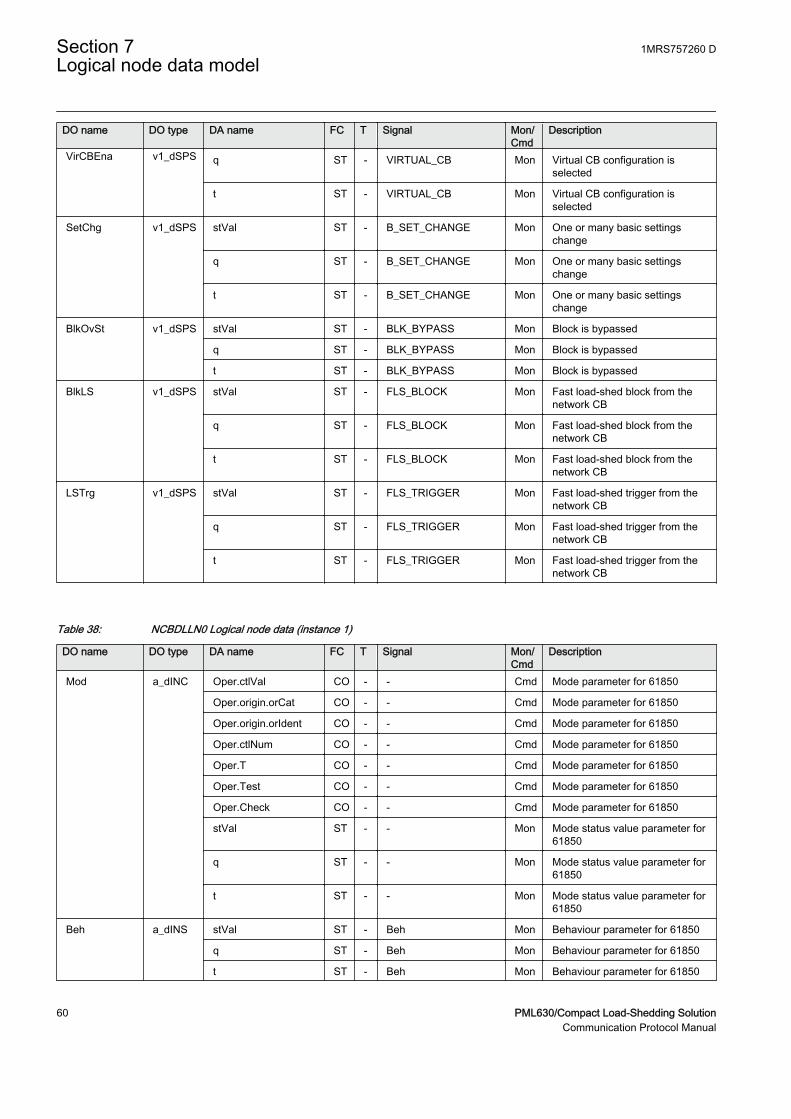
DO name DO type DA name FC T Signal Mon/Cmd
Description
VirCBEna v1_dSPS q ST - VIRTUAL_CB Mon Virtual CB configuration isselected
t ST - VIRTUAL_CB Mon Virtual CB configuration isselected
SetChg v1_dSPS stVal ST - B_SET_CHANGE Mon One or many basic settingschange
q ST - B_SET_CHANGE Mon One or many basic settingschange
t ST - B_SET_CHANGE Mon One or many basic settingschange
BlkOvSt v1_dSPS stVal ST - BLK_BYPASS Mon Block is bypassed
q ST - BLK_BYPASS Mon Block is bypassed
t ST - BLK_BYPASS Mon Block is bypassed
BlkLS v1_dSPS stVal ST - FLS_BLOCK Mon Fast load-shed block from thenetwork CB
q ST - FLS_BLOCK Mon Fast load-shed block from thenetwork CB
t ST - FLS_BLOCK Mon Fast load-shed block from thenetwork CB
LSTrg v1_dSPS stVal ST - FLS_TRIGGER Mon Fast load-shed trigger from thenetwork CB
q ST - FLS_TRIGGER Mon Fast load-shed trigger from thenetwork CB
t ST - FLS_TRIGGER Mon Fast load-shed trigger from thenetwork CB
Table 38: NCBDLLN0 Logical node data (instance 1)
DO name DO type DA name FC T Signal Mon/Cmd
Description
Mod a_dINC Oper.ctlVal CO - - Cmd Mode parameter for 61850
Oper.origin.orCat CO - - Cmd Mode parameter for 61850
Oper.origin.orIdent CO - - Cmd Mode parameter for 61850
Oper.ctlNum CO - - Cmd Mode parameter for 61850
Oper.T CO - - Cmd Mode parameter for 61850
Oper.Test CO - - Cmd Mode parameter for 61850
Oper.Check CO - - Cmd Mode parameter for 61850
stVal ST - - Mon Mode status value parameter for61850
q ST - - Mon Mode status value parameter for61850
t ST - - Mon Mode status value parameter for61850
Beh a_dINS stVal ST - Beh Mon Behaviour parameter for 61850
q ST - Beh Mon Behaviour parameter for 61850
t ST - Beh Mon Behaviour parameter for 61850
Section 7 1MRS757260 DLogical node data model
60 PML630/Compact Load-Shedding SolutionCommunication Protocol Manual

Table 39: NCBDMMXU Logical node data (instance 1)
DO name DO type DA name FC T Signal Mon/Cmd
Description
Beh a_dINS stVal ST - Beh Mon Behaviour parameter for 61850
q ST - Beh Mon Behaviour parameter for 61850
t ST - Beh Mon Behaviour parameter for 61850
Mod c_dINC stVal ST - - Mon Mode status value parameter for61850
q ST - - Mon Mode status value parameter for61850
t ST - - Mon Mode status value parameter for61850
TotW c_dMV mag.f MX - CB_POWER Mon Active power of network CB
q MX - CB_POWER Mon Active power of network CB
t MX - CB_POWER Mon Active power of network CB
7.4.4 Input interface function for network power data NPMMXU
LN type LN prefix LN class Function block name
NPMMXU (revision 0) NP MMXU NPMMXU
Table 40: NPMMXU Logical node data
DO name DO type DA name FC T Signal Mon/Cmd
Description
Mod a_dINC Oper.ctlVal CO - - Cmd Mode parameter for 61850
Oper.origin.orCat CO - - Cmd Mode parameter for 61850
Oper.origin.orIdent CO - - Cmd Mode parameter for 61850
Oper.ctlNum CO - - Cmd Mode parameter for 61850
Oper.T CO - - Cmd Mode parameter for 61850
Oper.Test CO - - Cmd Mode parameter for 61850
Oper.Check CO - - Cmd Mode parameter for 61850
Beh a_dINS stVal ST - Beh Mon Behaviour parameter for 61850
q ST - Beh Mon Behaviour parameter for 61850
t ST - Beh Mon Behaviour parameter for 61850
AvaPwrSrc1 v2_dMV mag.f MX - AVA_POW_SRC1 Mon Available power of power source1
q MX - AVA_POW_SRC1 Mon Available power of power source1
t MX - AVA_POW_SRC1 Mon Available power of power source1
AvaPwrSrc2 v2_dMV mag.f MX - AVA_POW_SRC2 Mon Available power of power source2
q MX - AVA_POW_SRC2 Mon Available power of power source2
t MX - AVA_POW_SRC2 Mon Available power of power source2
TotWSrc1 v2_dMV mag.f MX - ACT_POW_SRC1 Mon Active power of source1
Table continues on next page
1MRS757260 D Section 7Logical node data model
PML630/Compact Load-Shedding Solution 61Communication Protocol Manual
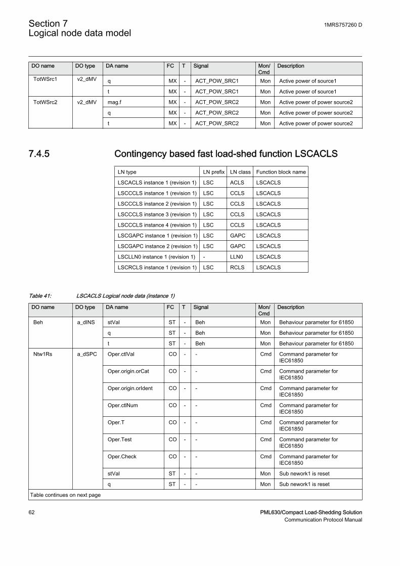
DO name DO type DA name FC T Signal Mon/Cmd
Description
TotWSrc1 v2_dMV q MX - ACT_POW_SRC1 Mon Active power of source1
t MX - ACT_POW_SRC1 Mon Active power of source1
TotWSrc2 v2_dMV mag.f MX - ACT_POW_SRC2 Mon Active power of power source2
q MX - ACT_POW_SRC2 Mon Active power of power source2
t MX - ACT_POW_SRC2 Mon Active power of power source2
7.4.5 Contingency based fast load-shed function LSCACLS
LN type LN prefix LN class Function block name
LSCACLS instance 1 (revision 1) LSC ACLS LSCACLS
LSCCCLS instance 1 (revision 1) LSC CCLS LSCACLS
LSCCCLS instance 2 (revision 1) LSC CCLS LSCACLS
LSCCCLS instance 3 (revision 1) LSC CCLS LSCACLS
LSCCCLS instance 4 (revision 1) LSC CCLS LSCACLS
LSCGAPC instance 1 (revision 1) LSC GAPC LSCACLS
LSCGAPC instance 2 (revision 1) LSC GAPC LSCACLS
LSCLLN0 instance 1 (revision 1) - LLN0 LSCACLS
LSCRCLS instance 1 (revision 1) LSC RCLS LSCACLS
Table 41: LSCACLS Logical node data (instance 1)
DO name DO type DA name FC T Signal Mon/Cmd
Description
Beh a_dINS stVal ST - Beh Mon Behaviour parameter for 61850
q ST - Beh Mon Behaviour parameter for 61850
t ST - Beh Mon Behaviour parameter for 61850
Ntw1Rs a_dSPC Oper.ctlVal CO - - Cmd Command parameter forIEC61850
Oper.origin.orCat CO - - Cmd Command parameter forIEC61850
Oper.origin.orIdent CO - - Cmd Command parameter forIEC61850
Oper.ctlNum CO - - Cmd Command parameter forIEC61850
Oper.T CO - - Cmd Command parameter forIEC61850
Oper.Test CO - - Cmd Command parameter forIEC61850
Oper.Check CO - - Cmd Command parameter forIEC61850
stVal ST - - Mon Sub nework1 is reset
q ST - - Mon Sub nework1 is reset
Table continues on next page
Section 7 1MRS757260 DLogical node data model
62 PML630/Compact Load-Shedding SolutionCommunication Protocol Manual
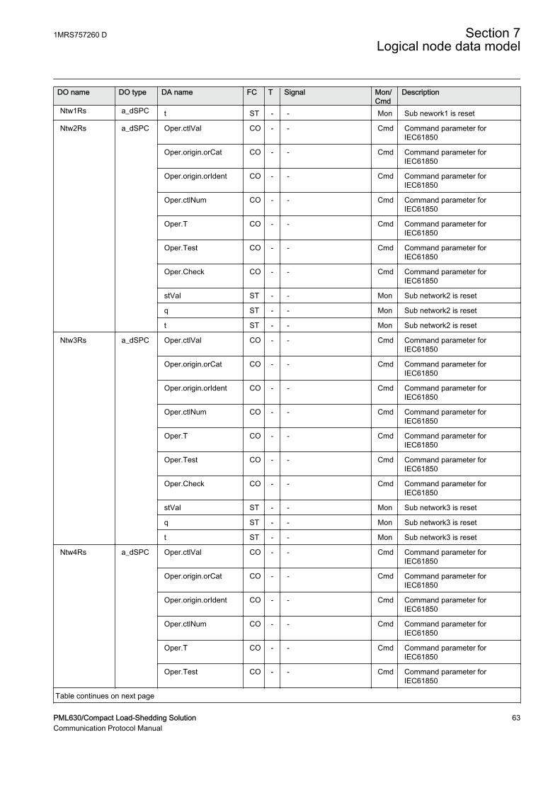
DO name DO type DA name FC T Signal Mon/Cmd
Description
Ntw1Rs a_dSPC t ST - - Mon Sub nework1 is reset
Ntw2Rs a_dSPC Oper.ctlVal CO - - Cmd Command parameter forIEC61850
Oper.origin.orCat CO - - Cmd Command parameter forIEC61850
Oper.origin.orIdent CO - - Cmd Command parameter forIEC61850
Oper.ctlNum CO - - Cmd Command parameter forIEC61850
Oper.T CO - - Cmd Command parameter forIEC61850
Oper.Test CO - - Cmd Command parameter forIEC61850
Oper.Check CO - - Cmd Command parameter forIEC61850
stVal ST - - Mon Sub network2 is reset
q ST - - Mon Sub network2 is reset
t ST - - Mon Sub network2 is reset
Ntw3Rs a_dSPC Oper.ctlVal CO - - Cmd Command parameter forIEC61850
Oper.origin.orCat CO - - Cmd Command parameter forIEC61850
Oper.origin.orIdent CO - - Cmd Command parameter forIEC61850
Oper.ctlNum CO - - Cmd Command parameter forIEC61850
Oper.T CO - - Cmd Command parameter forIEC61850
Oper.Test CO - - Cmd Command parameter forIEC61850
Oper.Check CO - - Cmd Command parameter forIEC61850
stVal ST - - Mon Sub network3 is reset
q ST - - Mon Sub network3 is reset
t ST - - Mon Sub network3 is reset
Ntw4Rs a_dSPC Oper.ctlVal CO - - Cmd Command parameter forIEC61850
Oper.origin.orCat CO - - Cmd Command parameter forIEC61850
Oper.origin.orIdent CO - - Cmd Command parameter forIEC61850
Oper.ctlNum CO - - Cmd Command parameter forIEC61850
Oper.T CO - - Cmd Command parameter forIEC61850
Oper.Test CO - - Cmd Command parameter forIEC61850
Table continues on next page
1MRS757260 D Section 7Logical node data model
PML630/Compact Load-Shedding Solution 63Communication Protocol Manual
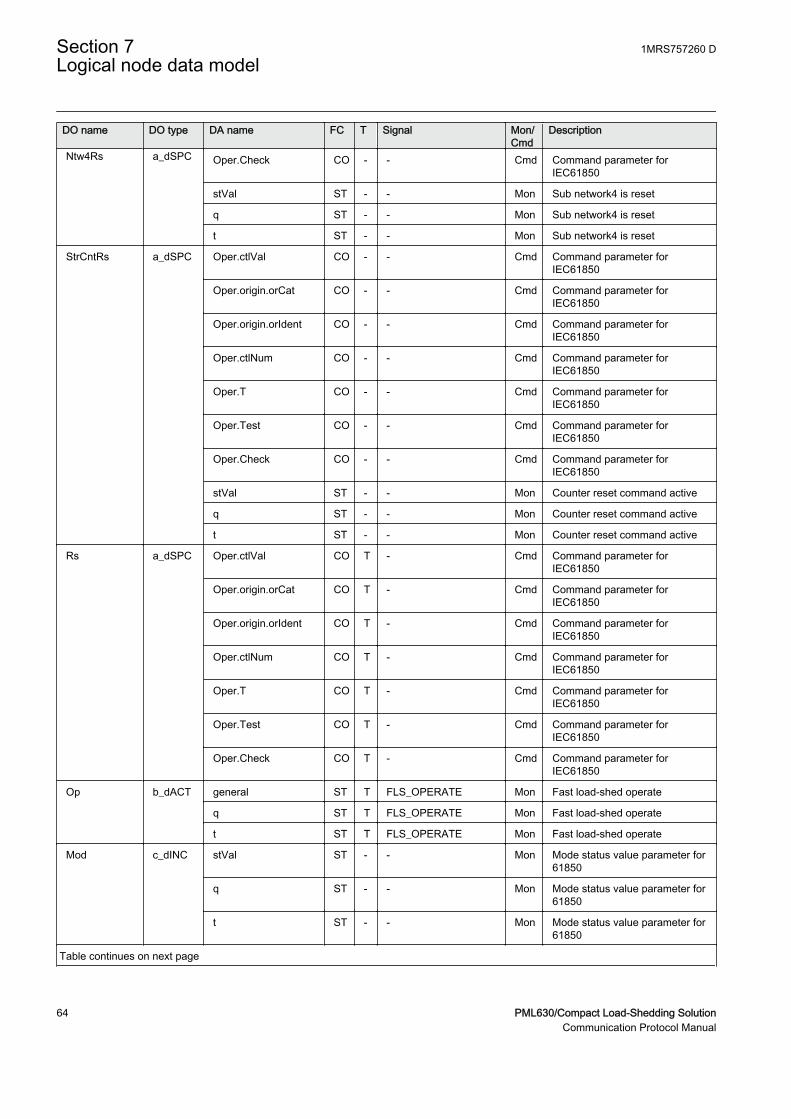
DO name DO type DA name FC T Signal Mon/Cmd
Description
Ntw4Rs a_dSPC Oper.Check CO - - Cmd Command parameter forIEC61850
stVal ST - - Mon Sub network4 is reset
q ST - - Mon Sub network4 is reset
t ST - - Mon Sub network4 is reset
StrCntRs a_dSPC Oper.ctlVal CO - - Cmd Command parameter forIEC61850
Oper.origin.orCat CO - - Cmd Command parameter forIEC61850
Oper.origin.orIdent CO - - Cmd Command parameter forIEC61850
Oper.ctlNum CO - - Cmd Command parameter forIEC61850
Oper.T CO - - Cmd Command parameter forIEC61850
Oper.Test CO - - Cmd Command parameter forIEC61850
Oper.Check CO - - Cmd Command parameter forIEC61850
stVal ST - - Mon Counter reset command active
q ST - - Mon Counter reset command active
t ST - - Mon Counter reset command active
Rs a_dSPC Oper.ctlVal CO T - Cmd Command parameter forIEC61850
Oper.origin.orCat CO T - Cmd Command parameter forIEC61850
Oper.origin.orIdent CO T - Cmd Command parameter forIEC61850
Oper.ctlNum CO T - Cmd Command parameter forIEC61850
Oper.T CO T - Cmd Command parameter forIEC61850
Oper.Test CO T - Cmd Command parameter forIEC61850
Oper.Check CO T - Cmd Command parameter forIEC61850
Op b_dACT general ST T FLS_OPERATE Mon Fast load-shed operate
q ST T FLS_OPERATE Mon Fast load-shed operate
t ST T FLS_OPERATE Mon Fast load-shed operate
Mod c_dINC stVal ST - - Mon Mode status value parameter for61850
q ST - - Mon Mode status value parameter for61850
t ST - - Mon Mode status value parameter for61850
Table continues on next page
Section 7 1MRS757260 DLogical node data model
64 PML630/Compact Load-Shedding SolutionCommunication Protocol Manual
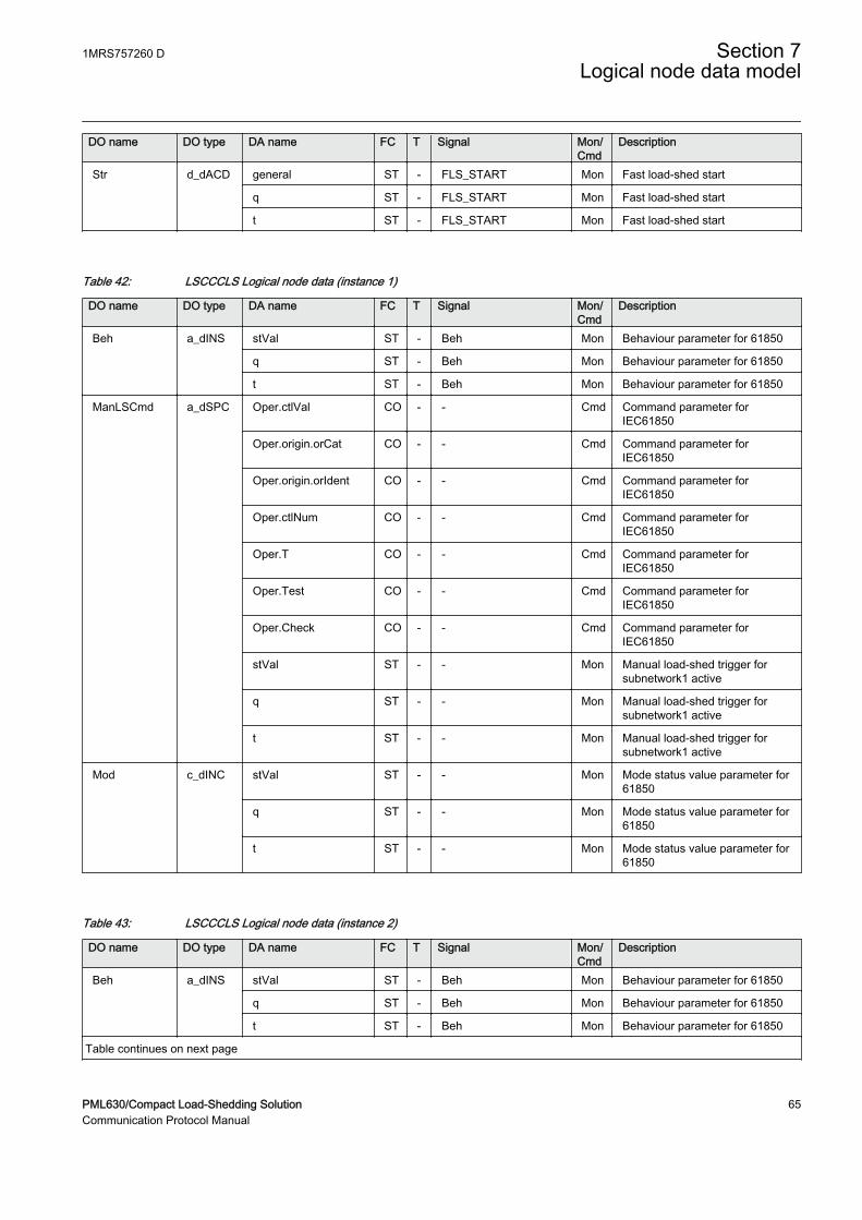
DO name DO type DA name FC T Signal Mon/Cmd
Description
Str d_dACD general ST - FLS_START Mon Fast load-shed start
q ST - FLS_START Mon Fast load-shed start
t ST - FLS_START Mon Fast load-shed start
Table 42: LSCCCLS Logical node data (instance 1)
DO name DO type DA name FC T Signal Mon/Cmd
Description
Beh a_dINS stVal ST - Beh Mon Behaviour parameter for 61850
q ST - Beh Mon Behaviour parameter for 61850
t ST - Beh Mon Behaviour parameter for 61850
ManLSCmd a_dSPC Oper.ctlVal CO - - Cmd Command parameter forIEC61850
Oper.origin.orCat CO - - Cmd Command parameter forIEC61850
Oper.origin.orIdent CO - - Cmd Command parameter forIEC61850
Oper.ctlNum CO - - Cmd Command parameter forIEC61850
Oper.T CO - - Cmd Command parameter forIEC61850
Oper.Test CO - - Cmd Command parameter forIEC61850
Oper.Check CO - - Cmd Command parameter forIEC61850
stVal ST - - Mon Manual load-shed trigger forsubnetwork1 active
q ST - - Mon Manual load-shed trigger forsubnetwork1 active
t ST - - Mon Manual load-shed trigger forsubnetwork1 active
Mod c_dINC stVal ST - - Mon Mode status value parameter for61850
q ST - - Mon Mode status value parameter for61850
t ST - - Mon Mode status value parameter for61850
Table 43: LSCCCLS Logical node data (instance 2)
DO name DO type DA name FC T Signal Mon/Cmd
Description
Beh a_dINS stVal ST - Beh Mon Behaviour parameter for 61850
q ST - Beh Mon Behaviour parameter for 61850
t ST - Beh Mon Behaviour parameter for 61850
Table continues on next page
1MRS757260 D Section 7Logical node data model
PML630/Compact Load-Shedding Solution 65Communication Protocol Manual
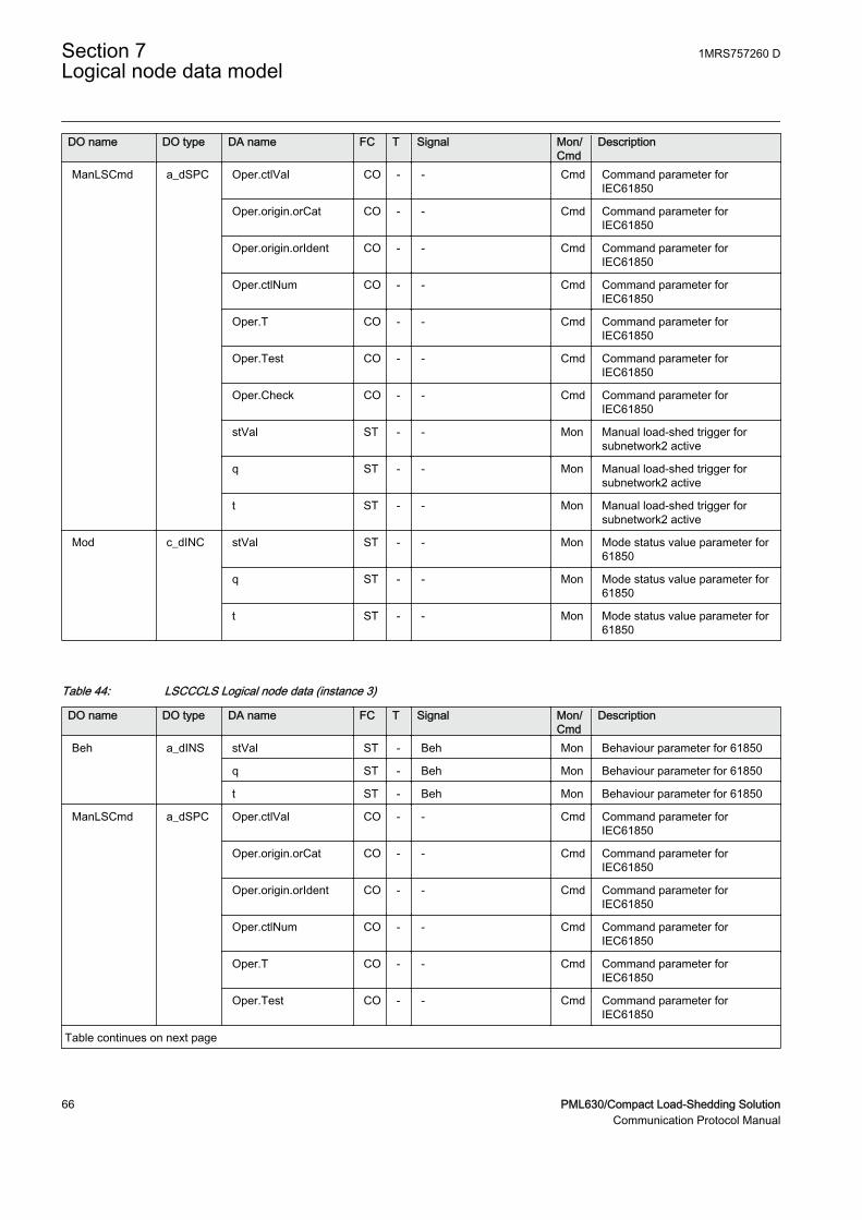
DO name DO type DA name FC T Signal Mon/Cmd
Description
ManLSCmd a_dSPC Oper.ctlVal CO - - Cmd Command parameter forIEC61850
Oper.origin.orCat CO - - Cmd Command parameter forIEC61850
Oper.origin.orIdent CO - - Cmd Command parameter forIEC61850
Oper.ctlNum CO - - Cmd Command parameter forIEC61850
Oper.T CO - - Cmd Command parameter forIEC61850
Oper.Test CO - - Cmd Command parameter forIEC61850
Oper.Check CO - - Cmd Command parameter forIEC61850
stVal ST - - Mon Manual load-shed trigger forsubnetwork2 active
q ST - - Mon Manual load-shed trigger forsubnetwork2 active
t ST - - Mon Manual load-shed trigger forsubnetwork2 active
Mod c_dINC stVal ST - - Mon Mode status value parameter for61850
q ST - - Mon Mode status value parameter for61850
t ST - - Mon Mode status value parameter for61850
Table 44: LSCCCLS Logical node data (instance 3)
DO name DO type DA name FC T Signal Mon/Cmd
Description
Beh a_dINS stVal ST - Beh Mon Behaviour parameter for 61850
q ST - Beh Mon Behaviour parameter for 61850
t ST - Beh Mon Behaviour parameter for 61850
ManLSCmd a_dSPC Oper.ctlVal CO - - Cmd Command parameter forIEC61850
Oper.origin.orCat CO - - Cmd Command parameter forIEC61850
Oper.origin.orIdent CO - - Cmd Command parameter forIEC61850
Oper.ctlNum CO - - Cmd Command parameter forIEC61850
Oper.T CO - - Cmd Command parameter forIEC61850
Oper.Test CO - - Cmd Command parameter forIEC61850
Table continues on next page
Section 7 1MRS757260 DLogical node data model
66 PML630/Compact Load-Shedding SolutionCommunication Protocol Manual
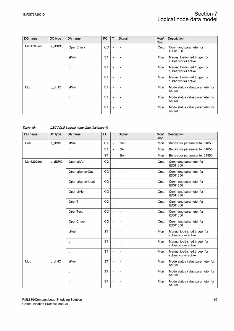
DO name DO type DA name FC T Signal Mon/Cmd
Description
ManLSCmd a_dSPC Oper.Check CO - - Cmd Command parameter forIEC61850
stVal ST - - Mon Manual load-shed trigger forsubnetwork3 active
q ST - - Mon Manual load-shed trigger forsubnetwork3 active
t ST - - Mon Manual load-shed trigger forsubnetwork3 active
Mod c_dINC stVal ST - - Mon Mode status value parameter for61850
q ST - - Mon Mode status value parameter for61850
t ST - - Mon Mode status value parameter for61850
Table 45: LSCCCLS Logical node data (instance 4)
DO name DO type DA name FC T Signal Mon/Cmd
Description
Beh a_dINS stVal ST - Beh Mon Behaviour parameter for 61850
q ST - Beh Mon Behaviour parameter for 61850
t ST - Beh Mon Behaviour parameter for 61850
ManLSCmd a_dSPC Oper.ctlVal CO - - Cmd Command parameter forIEC61850
Oper.origin.orCat CO - - Cmd Command parameter forIEC61850
Oper.origin.orIdent CO - - Cmd Command parameter forIEC61850
Oper.ctlNum CO - - Cmd Command parameter forIEC61850
Oper.T CO - - Cmd Command parameter forIEC61850
Oper.Test CO - - Cmd Command parameter forIEC61850
Oper.Check CO - - Cmd Command parameter forIEC61850
stVal ST - - Mon Manual load-shed trigger forsubnetwork4 active
q ST - - Mon Manual load-shed trigger forsubnetwork4 active
t ST - - Mon Manual load-shed trigger forsubnetwork4 active
Mod c_dINC stVal ST - - Mon Mode status value parameter for61850
q ST - - Mon Mode status value parameter for61850
t ST - - Mon Mode status value parameter for61850
1MRS757260 D Section 7Logical node data model
PML630/Compact Load-Shedding Solution 67Communication Protocol Manual
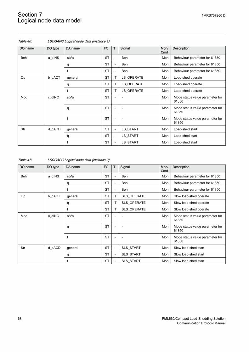
Table 46: LSCGAPC Logical node data (instance 1)
DO name DO type DA name FC T Signal Mon/Cmd
Description
Beh a_dINS stVal ST - Beh Mon Behaviour parameter for 61850
q ST - Beh Mon Behaviour parameter for 61850
t ST - Beh Mon Behaviour parameter for 61850
Op b_dACT general ST T LS_OPERATE Mon Load-shed operate
q ST T LS_OPERATE Mon Load-shed operate
t ST T LS_OPERATE Mon Load-shed operate
Mod c_dINC stVal ST - - Mon Mode status value parameter for61850
q ST - - Mon Mode status value parameter for61850
t ST - - Mon Mode status value parameter for61850
Str d_dACD general ST - LS_START Mon Load-shed start
q ST - LS_START Mon Load-shed start
t ST - LS_START Mon Load-shed start
Table 47: LSCGAPC Logical node data (instance 2)
DO name DO type DA name FC T Signal Mon/Cmd
Description
Beh a_dINS stVal ST - Beh Mon Behaviour parameter for 61850
q ST - Beh Mon Behaviour parameter for 61850
t ST - Beh Mon Behaviour parameter for 61850
Op b_dACT general ST T SLS_OPERATE Mon Slow load-shed operate
q ST T SLS_OPERATE Mon Slow load-shed operate
t ST T SLS_OPERATE Mon Slow load-shed operate
Mod c_dINC stVal ST - - Mon Mode status value parameter for61850
q ST - - Mon Mode status value parameter for61850
t ST - - Mon Mode status value parameter for61850
Str d_dACD general ST - SLS_START Mon Slow load-shed start
q ST - SLS_START Mon Slow load-shed start
t ST - SLS_START Mon Slow load-shed start
Section 7 1MRS757260 DLogical node data model
68 PML630/Compact Load-Shedding SolutionCommunication Protocol Manual
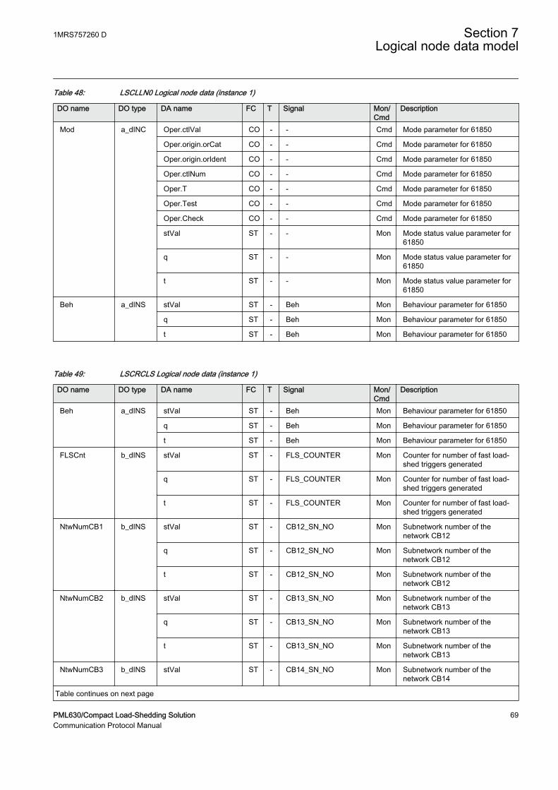
Table 48: LSCLLN0 Logical node data (instance 1)
DO name DO type DA name FC T Signal Mon/Cmd
Description
Mod a_dINC Oper.ctlVal CO - - Cmd Mode parameter for 61850
Oper.origin.orCat CO - - Cmd Mode parameter for 61850
Oper.origin.orIdent CO - - Cmd Mode parameter for 61850
Oper.ctlNum CO - - Cmd Mode parameter for 61850
Oper.T CO - - Cmd Mode parameter for 61850
Oper.Test CO - - Cmd Mode parameter for 61850
Oper.Check CO - - Cmd Mode parameter for 61850
stVal ST - - Mon Mode status value parameter for61850
q ST - - Mon Mode status value parameter for61850
t ST - - Mon Mode status value parameter for61850
Beh a_dINS stVal ST - Beh Mon Behaviour parameter for 61850
q ST - Beh Mon Behaviour parameter for 61850
t ST - Beh Mon Behaviour parameter for 61850
Table 49: LSCRCLS Logical node data (instance 1)
DO name DO type DA name FC T Signal Mon/Cmd
Description
Beh a_dINS stVal ST - Beh Mon Behaviour parameter for 61850
q ST - Beh Mon Behaviour parameter for 61850
t ST - Beh Mon Behaviour parameter for 61850
FLSCnt b_dINS stVal ST - FLS_COUNTER Mon Counter for number of fast load-shed triggers generated
q ST - FLS_COUNTER Mon Counter for number of fast load-shed triggers generated
t ST - FLS_COUNTER Mon Counter for number of fast load-shed triggers generated
NtwNumCB1 b_dINS stVal ST - CB12_SN_NO Mon Subnetwork number of thenetwork CB12
q ST - CB12_SN_NO Mon Subnetwork number of thenetwork CB12
t ST - CB12_SN_NO Mon Subnetwork number of thenetwork CB12
NtwNumCB2 b_dINS stVal ST - CB13_SN_NO Mon Subnetwork number of thenetwork CB13
q ST - CB13_SN_NO Mon Subnetwork number of thenetwork CB13
t ST - CB13_SN_NO Mon Subnetwork number of thenetwork CB13
NtwNumCB3 b_dINS stVal ST - CB14_SN_NO Mon Subnetwork number of thenetwork CB14
Table continues on next page
1MRS757260 D Section 7Logical node data model
PML630/Compact Load-Shedding Solution 69Communication Protocol Manual
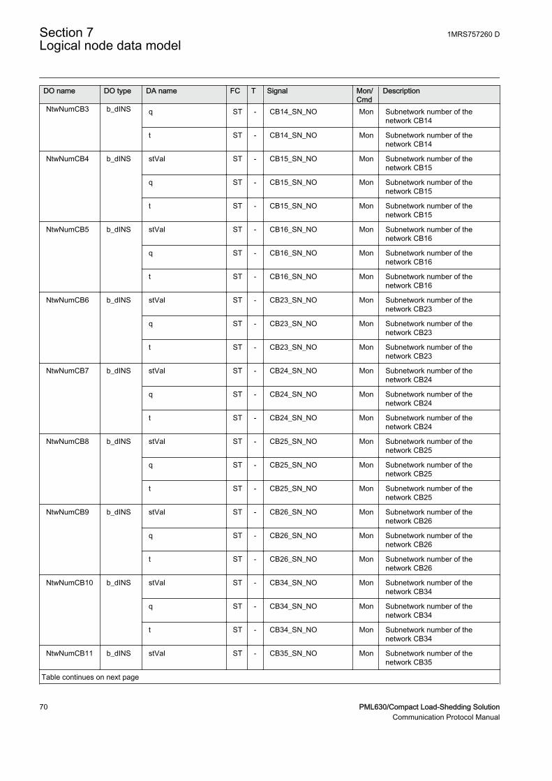
DO name DO type DA name FC T Signal Mon/Cmd
Description
NtwNumCB3 b_dINS q ST - CB14_SN_NO Mon Subnetwork number of thenetwork CB14
t ST - CB14_SN_NO Mon Subnetwork number of thenetwork CB14
NtwNumCB4 b_dINS stVal ST - CB15_SN_NO Mon Subnetwork number of thenetwork CB15
q ST - CB15_SN_NO Mon Subnetwork number of thenetwork CB15
t ST - CB15_SN_NO Mon Subnetwork number of thenetwork CB15
NtwNumCB5 b_dINS stVal ST - CB16_SN_NO Mon Subnetwork number of thenetwork CB16
q ST - CB16_SN_NO Mon Subnetwork number of thenetwork CB16
t ST - CB16_SN_NO Mon Subnetwork number of thenetwork CB16
NtwNumCB6 b_dINS stVal ST - CB23_SN_NO Mon Subnetwork number of thenetwork CB23
q ST - CB23_SN_NO Mon Subnetwork number of thenetwork CB23
t ST - CB23_SN_NO Mon Subnetwork number of thenetwork CB23
NtwNumCB7 b_dINS stVal ST - CB24_SN_NO Mon Subnetwork number of thenetwork CB24
q ST - CB24_SN_NO Mon Subnetwork number of thenetwork CB24
t ST - CB24_SN_NO Mon Subnetwork number of thenetwork CB24
NtwNumCB8 b_dINS stVal ST - CB25_SN_NO Mon Subnetwork number of thenetwork CB25
q ST - CB25_SN_NO Mon Subnetwork number of thenetwork CB25
t ST - CB25_SN_NO Mon Subnetwork number of thenetwork CB25
NtwNumCB9 b_dINS stVal ST - CB26_SN_NO Mon Subnetwork number of thenetwork CB26
q ST - CB26_SN_NO Mon Subnetwork number of thenetwork CB26
t ST - CB26_SN_NO Mon Subnetwork number of thenetwork CB26
NtwNumCB10 b_dINS stVal ST - CB34_SN_NO Mon Subnetwork number of thenetwork CB34
q ST - CB34_SN_NO Mon Subnetwork number of thenetwork CB34
t ST - CB34_SN_NO Mon Subnetwork number of thenetwork CB34
NtwNumCB11 b_dINS stVal ST - CB35_SN_NO Mon Subnetwork number of thenetwork CB35
Table continues on next page
Section 7 1MRS757260 DLogical node data model
70 PML630/Compact Load-Shedding SolutionCommunication Protocol Manual
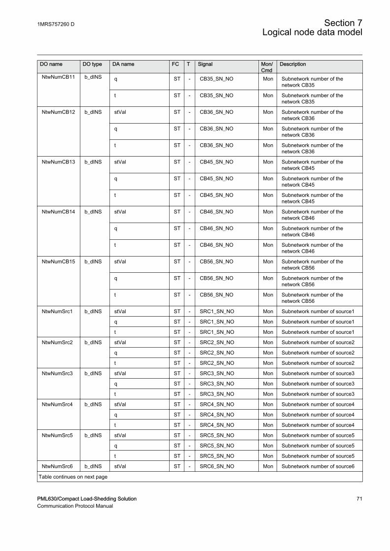
DO name DO type DA name FC T Signal Mon/Cmd
Description
NtwNumCB11 b_dINS q ST - CB35_SN_NO Mon Subnetwork number of thenetwork CB35
t ST - CB35_SN_NO Mon Subnetwork number of thenetwork CB35
NtwNumCB12 b_dINS stVal ST - CB36_SN_NO Mon Subnetwork number of thenetwork CB36
q ST - CB36_SN_NO Mon Subnetwork number of thenetwork CB36
t ST - CB36_SN_NO Mon Subnetwork number of thenetwork CB36
NtwNumCB13 b_dINS stVal ST - CB45_SN_NO Mon Subnetwork number of thenetwork CB45
q ST - CB45_SN_NO Mon Subnetwork number of thenetwork CB45
t ST - CB45_SN_NO Mon Subnetwork number of thenetwork CB45
NtwNumCB14 b_dINS stVal ST - CB46_SN_NO Mon Subnetwork number of thenetwork CB46
q ST - CB46_SN_NO Mon Subnetwork number of thenetwork CB46
t ST - CB46_SN_NO Mon Subnetwork number of thenetwork CB46
NtwNumCB15 b_dINS stVal ST - CB56_SN_NO Mon Subnetwork number of thenetwork CB56
q ST - CB56_SN_NO Mon Subnetwork number of thenetwork CB56
t ST - CB56_SN_NO Mon Subnetwork number of thenetwork CB56
NtwNumSrc1 b_dINS stVal ST - SRC1_SN_NO Mon Subnetwork number of source1
q ST - SRC1_SN_NO Mon Subnetwork number of source1
t ST - SRC1_SN_NO Mon Subnetwork number of source1
NtwNumSrc2 b_dINS stVal ST - SRC2_SN_NO Mon Subnetwork number of source2
q ST - SRC2_SN_NO Mon Subnetwork number of source2
t ST - SRC2_SN_NO Mon Subnetwork number of source2
NtwNumSrc3 b_dINS stVal ST - SRC3_SN_NO Mon Subnetwork number of source3
q ST - SRC3_SN_NO Mon Subnetwork number of source3
t ST - SRC3_SN_NO Mon Subnetwork number of source3
NtwNumSrc4 b_dINS stVal ST - SRC4_SN_NO Mon Subnetwork number of source4
q ST - SRC4_SN_NO Mon Subnetwork number of source4
t ST - SRC4_SN_NO Mon Subnetwork number of source4
NtwNumSrc5 b_dINS stVal ST - SRC5_SN_NO Mon Subnetwork number of source5
q ST - SRC5_SN_NO Mon Subnetwork number of source5
t ST - SRC5_SN_NO Mon Subnetwork number of source5
NtwNumSrc6 b_dINS stVal ST - SRC6_SN_NO Mon Subnetwork number of source6
Table continues on next page
1MRS757260 D Section 7Logical node data model
PML630/Compact Load-Shedding Solution 71Communication Protocol Manual

DO name DO type DA name FC T Signal Mon/Cmd
Description
NtwNumSrc6 b_dINS q ST - SRC6_SN_NO Mon Subnetwork number of source6
t ST - SRC6_SN_NO Mon Subnetwork number of source6
NtwNumSrc7 b_dINS stVal ST - SRC7_SN_NO Mon Subnetwork number of source7
q ST - SRC7_SN_NO Mon Subnetwork number of source7
t ST - SRC7_SN_NO Mon Subnetwork number of source7
NtwNumSrc8 b_dINS stVal ST - SRC8_SN_NO Mon Subnetwork number of source8
q ST - SRC8_SN_NO Mon Subnetwork number of source8
t ST - SRC8_SN_NO Mon Subnetwork number of source8
NtwNumBB1 b_dINS stVal ST - BB1_SN_NO Mon Subnetwork number of busbar1
q ST - BB1_SN_NO Mon Subnetwork number of busbar1
t ST - BB1_SN_NO Mon Subnetwork number of busbar1
NtwNumBB2 b_dINS stVal ST - BB2_SN_NO Mon Subnetwork number of busbar2
q ST - BB2_SN_NO Mon Subnetwork number of busbar2
t ST - BB2_SN_NO Mon Subnetwork number of busbar2
NtwNumBB3 b_dINS stVal ST - BB3_SN_NO Mon Subnetwork number of busbar3
q ST - BB3_SN_NO Mon Subnetwork number of busbar3
t ST - BB3_SN_NO Mon Subnetwork number of busbar3
NtwNumBB4 b_dINS stVal ST - BB4_SN_NO Mon Sub network number of busbar4
q ST - BB4_SN_NO Mon Sub network number of busbar4
t ST - BB4_SN_NO Mon Sub network number of busbar4
NtwNumBB5 b_dINS stVal ST - BB5_SN_NO Mon Subnetwork number of busbar5
q ST - BB5_SN_NO Mon Subnetwork number of busbar5
t ST - BB5_SN_NO Mon Subnetwork number of busbar5
NtwNumBB6 b_dINS stVal ST - BB6_SN_NO Mon Subnetwork number of busbar6
q ST - BB6_SN_NO Mon Subnetwork number of busbar6
t ST - BB6_SN_NO Mon Subnetwork number of busbar6
ManLSBeh b_dINS stVal ST - MAN_LS_BEH Mon Manual load-shed behaviour
q ST - MAN_LS_BEH Mon Manual load-shed behaviour
t ST - MAN_LS_BEH Mon Manual load-shed behaviour
Mod c_dINC stVal ST - - Mon Mode status value parameter for61850
q ST - - Mon Mode status value parameter for61850
t ST - - Mon Mode status value parameter for61850
SetChg c_dSPS stVal ST - B_SET_CHANGE Mon One or many basic settingschanged
q ST - B_SET_CHANGE Mon One or many basic settingschanged
t ST - B_SET_CHANGE Mon One or many basic settingschanged
Section 7 1MRS757260 DLogical node data model
72 PML630/Compact Load-Shedding SolutionCommunication Protocol Manual

7.4.6 Sheddable load trip command LSPTRC
LN type LN prefix LN class Function block name
LSLLN0 instance 1 (revision 0) - LLN0 LSPTRC
LSPTRC instance 1 (revision 2) LS PTRC LSPTRC
LSPTRC instance 2 (revision 2) LS PTRC LSPTRC
LSPTRC instance 3 (revision 2) LS PTRC LSPTRC
LSPTRC instance 4 (revision 2) LS PTRC LSPTRC
LSPTRC instance 5 (revision 2) LS PTRC LSPTRC
LSPTRC instance 6 (revision 2) LS PTRC LSPTRC
LSPTRC instance 7 (revision 2) LS PTRC LSPTRC
LSPTRC instance 8 (revision 2) LS PTRC LSPTRC
LSPTRC instance 9 (revision 2) LS PTRC LSPTRC
LSPTRC instance 10 (revision 2) LS PTRC LSPTRC
Table 50: LSLLN0 Logical node data (instance 1)
DO name DO type DA name FC T Signal Mon/Cmd
Description
Mod a_dINC Oper.ctlVal CO - - Cmd Mode parameter for 61850
Oper.origin.orCat CO - - Cmd Mode parameter for 61850
Oper.origin.orIdent CO - - Cmd Mode parameter for 61850
Oper.ctlNum CO - - Cmd Mode parameter for 61850
Oper.T CO - - Cmd Mode parameter for 61850
Oper.Test CO - - Cmd Mode parameter for 61850
Oper.Check CO - - Cmd Mode parameter for 61850
stVal ST - - Mon Mode status value parameter for61850
q ST - - Mon Mode status value parameter for61850
t ST - - Mon Mode status value parameter for61850
Beh a_dINS stVal ST - Beh Mon Behaviour parameter for 61850
q ST - Beh Mon Behaviour parameter for 61850
t ST - Beh Mon Behaviour parameter for 61850
Table 51: LSPTRC Logical node data (instance 1)
DO name DO type DA name FC T Signal Mon/Cmd
Description
Beh a_dINS stVal ST - Beh Mon Behaviour parameter for 61850
q ST - Beh Mon Behaviour parameter for 61850
t ST - Beh Mon Behaviour parameter for 61850
Table continues on next page
1MRS757260 D Section 7Logical node data model
PML630/Compact Load-Shedding Solution 73Communication Protocol Manual
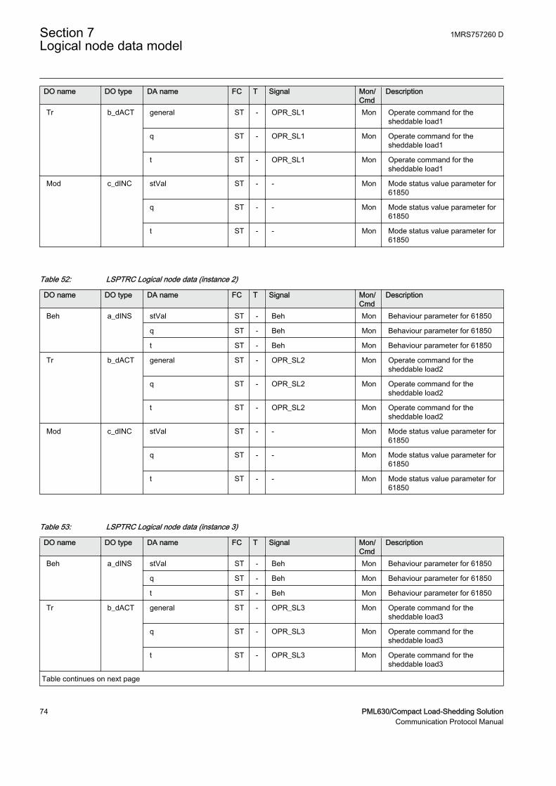
DO name DO type DA name FC T Signal Mon/Cmd
Description
Tr b_dACT general ST - OPR_SL1 Mon Operate command for thesheddable load1
q ST - OPR_SL1 Mon Operate command for thesheddable load1
t ST - OPR_SL1 Mon Operate command for thesheddable load1
Mod c_dINC stVal ST - - Mon Mode status value parameter for61850
q ST - - Mon Mode status value parameter for61850
t ST - - Mon Mode status value parameter for61850
Table 52: LSPTRC Logical node data (instance 2)
DO name DO type DA name FC T Signal Mon/Cmd
Description
Beh a_dINS stVal ST - Beh Mon Behaviour parameter for 61850
q ST - Beh Mon Behaviour parameter for 61850
t ST - Beh Mon Behaviour parameter for 61850
Tr b_dACT general ST - OPR_SL2 Mon Operate command for thesheddable load2
q ST - OPR_SL2 Mon Operate command for thesheddable load2
t ST - OPR_SL2 Mon Operate command for thesheddable load2
Mod c_dINC stVal ST - - Mon Mode status value parameter for61850
q ST - - Mon Mode status value parameter for61850
t ST - - Mon Mode status value parameter for61850
Table 53: LSPTRC Logical node data (instance 3)
DO name DO type DA name FC T Signal Mon/Cmd
Description
Beh a_dINS stVal ST - Beh Mon Behaviour parameter for 61850
q ST - Beh Mon Behaviour parameter for 61850
t ST - Beh Mon Behaviour parameter for 61850
Tr b_dACT general ST - OPR_SL3 Mon Operate command for thesheddable load3
q ST - OPR_SL3 Mon Operate command for thesheddable load3
t ST - OPR_SL3 Mon Operate command for thesheddable load3
Table continues on next page
Section 7 1MRS757260 DLogical node data model
74 PML630/Compact Load-Shedding SolutionCommunication Protocol Manual
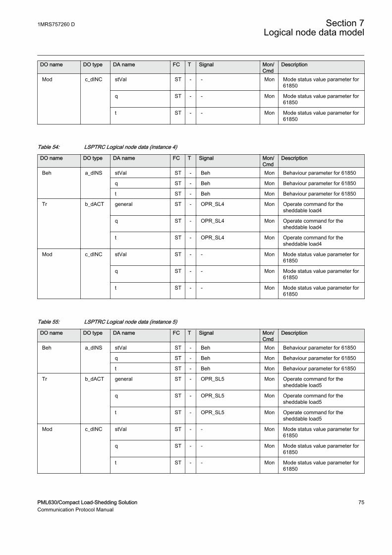
DO name DO type DA name FC T Signal Mon/Cmd
Description
Mod c_dINC stVal ST - - Mon Mode status value parameter for61850
q ST - - Mon Mode status value parameter for61850
t ST - - Mon Mode status value parameter for61850
Table 54: LSPTRC Logical node data (instance 4)
DO name DO type DA name FC T Signal Mon/Cmd
Description
Beh a_dINS stVal ST - Beh Mon Behaviour parameter for 61850
q ST - Beh Mon Behaviour parameter for 61850
t ST - Beh Mon Behaviour parameter for 61850
Tr b_dACT general ST - OPR_SL4 Mon Operate command for thesheddable load4
q ST - OPR_SL4 Mon Operate command for thesheddable load4
t ST - OPR_SL4 Mon Operate command for thesheddable load4
Mod c_dINC stVal ST - - Mon Mode status value parameter for61850
q ST - - Mon Mode status value parameter for61850
t ST - - Mon Mode status value parameter for61850
Table 55: LSPTRC Logical node data (instance 5)
DO name DO type DA name FC T Signal Mon/Cmd
Description
Beh a_dINS stVal ST - Beh Mon Behaviour parameter for 61850
q ST - Beh Mon Behaviour parameter for 61850
t ST - Beh Mon Behaviour parameter for 61850
Tr b_dACT general ST - OPR_SL5 Mon Operate command for thesheddable load5
q ST - OPR_SL5 Mon Operate command for thesheddable load5
t ST - OPR_SL5 Mon Operate command for thesheddable load5
Mod c_dINC stVal ST - - Mon Mode status value parameter for61850
q ST - - Mon Mode status value parameter for61850
t ST - - Mon Mode status value parameter for61850
1MRS757260 D Section 7Logical node data model
PML630/Compact Load-Shedding Solution 75Communication Protocol Manual

Table 56: LSPTRC Logical node data (instance 6)
DO name DO type DA name FC T Signal Mon/Cmd
Description
Beh a_dINS stVal ST - Beh Mon Behaviour parameter for 61850
q ST - Beh Mon Behaviour parameter for 61850
t ST - Beh Mon Behaviour parameter for 61850
Tr b_dACT general ST - OPR_SL6 Mon Operate command for thesheddable load6
q ST - OPR_SL6 Mon Operate command for thesheddable load6
t ST - OPR_SL6 Mon Operate command for thesheddable load6
Mod c_dINC stVal ST - - Mon Mode status value parameter for61850
q ST - - Mon Mode status value parameter for61850
t ST - - Mon Mode status value parameter for61850
Table 57: LSPTRC Logical node data (instance 7)
DO name DO type DA name FC T Signal Mon/Cmd
Description
Beh a_dINS stVal ST - Beh Mon Behaviour parameter for 61850
q ST - Beh Mon Behaviour parameter for 61850
t ST - Beh Mon Behaviour parameter for 61850
Tr b_dACT general ST - OPR_SL7 Mon Operate command for thesheddable load7
q ST - OPR_SL7 Mon Operate command for thesheddable load7
t ST - OPR_SL7 Mon Operate command for thesheddable load7
Mod c_dINC stVal ST - - Mon Mode status value parameter for61850
q ST - - Mon Mode status value parameter for61850
t ST - - Mon Mode status value parameter for61850
Table 58: LSPTRC Logical node data (instance 8)
DO name DO type DA name FC T Signal Mon/Cmd
Description
Beh a_dINS stVal ST - Beh Mon Behaviour parameter for 61850
q ST - Beh Mon Behaviour parameter for 61850
t ST - Beh Mon Behaviour parameter for 61850
Table continues on next page
Section 7 1MRS757260 DLogical node data model
76 PML630/Compact Load-Shedding SolutionCommunication Protocol Manual
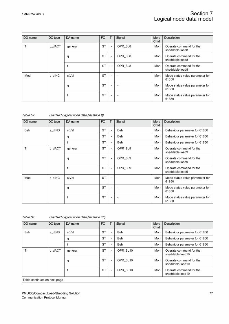
DO name DO type DA name FC T Signal Mon/Cmd
Description
Tr b_dACT general ST - OPR_SL8 Mon Operate command for thesheddable load8
q ST - OPR_SL8 Mon Operate command for thesheddable load8
t ST - OPR_SL8 Mon Operate command for thesheddable load8
Mod c_dINC stVal ST - - Mon Mode status value parameter for61850
q ST - - Mon Mode status value parameter for61850
t ST - - Mon Mode status value parameter for61850
Table 59: LSPTRC Logical node data (instance 9)
DO name DO type DA name FC T Signal Mon/Cmd
Description
Beh a_dINS stVal ST - Beh Mon Behaviour parameter for 61850
q ST - Beh Mon Behaviour parameter for 61850
t ST - Beh Mon Behaviour parameter for 61850
Tr b_dACT general ST - OPR_SL9 Mon Operate command for thesheddable load9
q ST - OPR_SL9 Mon Operate command for thesheddable load9
t ST - OPR_SL9 Mon Operate command for thesheddable load9
Mod c_dINC stVal ST - - Mon Mode status value parameter for61850
q ST - - Mon Mode status value parameter for61850
t ST - - Mon Mode status value parameter for61850
Table 60: LSPTRC Logical node data (instance 10)
DO name DO type DA name FC T Signal Mon/Cmd
Description
Beh a_dINS stVal ST - Beh Mon Behaviour parameter for 61850
q ST - Beh Mon Behaviour parameter for 61850
t ST - Beh Mon Behaviour parameter for 61850
Tr b_dACT general ST - OPR_SL10 Mon Operate command for thesheddable load10
q ST - OPR_SL10 Mon Operate command for thesheddable load10
t ST - OPR_SL10 Mon Operate command for thesheddable load10
Table continues on next page
1MRS757260 D Section 7Logical node data model
PML630/Compact Load-Shedding Solution 77Communication Protocol Manual
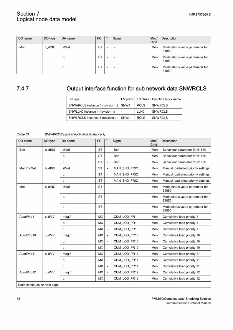
DO name DO type DA name FC T Signal Mon/Cmd
Description
Mod c_dINC stVal ST - - Mon Mode status value parameter for61850
q ST - - Mon Mode status value parameter for61850
t ST - - Mon Mode status value parameter for61850
7.4.7 Output interface function for sub network data SNWRCLS
LN type LN prefix LN class Function block name
SNWARCLS instance 1 (revision 1) SNWA RCLS SNWRCLS
SNWLLN0 instance 1 (revision 1) - LLN0 SNWRCLS
SNWLRCLS instance 1 (revision 1) SNWL RCLS SNWRCLS
Table 61: SNWARCLS Logical node data (instance 1)
DO name DO type DA name FC T Signal Mon/Cmd
Description
Beh a_dINS stVal ST - Beh Mon Behaviour parameter for 61850
q ST - Beh Mon Behaviour parameter for 61850
t ST - Beh Mon Behaviour parameter for 61850
ManPrioSet b_dINS stVal ST - MAN_SHD_PRIO Mon Manual load-shed priority settings
q ST - MAN_SHD_PRIO Mon Manual load-shed priority settings
t ST - MAN_SHD_PRIO Mon Manual load-shed priority settings
Mod c_dINC stVal ST - - Mon Mode status value parameter for61850
q ST - - Mon Mode status value parameter for61850
t ST - - Mon Mode status value parameter for61850
ALodPrio1 c_dMV mag.f MX - CUM_LOD_PR1 Mon Cumulative load priority 1
q MX - CUM_LOD_PR1 Mon Cumulative load priority 1
t MX - CUM_LOD_PR1 Mon Cumulative load priority 1
ALodPrio10 c_dMV mag.f MX - CUM_LOD_PR10 Mon Cumulative load priority 10
q MX - CUM_LOD_PR10 Mon Cumulative load priority 10
t MX - CUM_LOD_PR10 Mon Cumulative load priority 10
ALodPrio11 c_dMV mag.f MX - CUM_LOD_PR11 Mon Cumulative load priority 11
q MX - CUM_LOD_PR11 Mon Cumulative load priority 11
t MX - CUM_LOD_PR11 Mon Cumulative load priority 11
ALodPrio12 c_dMV mag.f MX - CUM_LOD_PR12 Mon Cumulative load priority 12
q MX - CUM_LOD_PR12 Mon Cumulative load priority 12
Table continues on next page
Section 7 1MRS757260 DLogical node data model
78 PML630/Compact Load-Shedding SolutionCommunication Protocol Manual
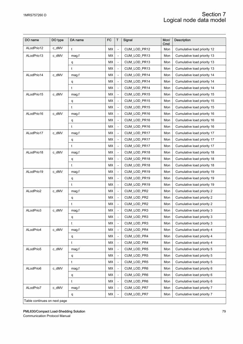
DO name DO type DA name FC T Signal Mon/Cmd
Description
ALodPrio12 c_dMV t MX - CUM_LOD_PR12 Mon Cumulative load priority 12
ALodPrio13 c_dMV mag.f MX - CUM_LOD_PR13 Mon Cumulative load priority 13
q MX - CUM_LOD_PR13 Mon Cumulative load priority 13
t MX - CUM_LOD_PR13 Mon Cumulative load priority 13
ALodPrio14 c_dMV mag.f MX - CUM_LOD_PR14 Mon Cumulative load priority 14
q MX - CUM_LOD_PR14 Mon Cumulative load priority 14
t MX - CUM_LOD_PR14 Mon Cumulative load priority 14
ALodPrio15 c_dMV mag.f MX - CUM_LOD_PR15 Mon Cumulative load priority 15
q MX - CUM_LOD_PR15 Mon Cumulative load priority 15
t MX - CUM_LOD_PR15 Mon Cumulative load priority 15
ALodPrio16 c_dMV mag.f MX - CUM_LOD_PR16 Mon Cumulative load priority 16
q MX - CUM_LOD_PR16 Mon Cumulative load priority 16
t MX - CUM_LOD_PR16 Mon Cumulative load priority 16
ALodPrio17 c_dMV mag.f MX - CUM_LOD_PR17 Mon Cumulative load priority 17
q MX - CUM_LOD_PR17 Mon Cumulative load priority 17
t MX - CUM_LOD_PR17 Mon Cumulative load priority 17
ALodPrio18 c_dMV mag.f MX - CUM_LOD_PR18 Mon Cumulative load priority 18
q MX - CUM_LOD_PR18 Mon Cumulative load priority 18
t MX - CUM_LOD_PR18 Mon Cumulative load priority 18
ALodPrio19 c_dMV mag.f MX - CUM_LOD_PR19 Mon Cumulative load priority 19
q MX - CUM_LOD_PR19 Mon Cumulative load priority 19
t MX - CUM_LOD_PR19 Mon Cumulative load priority 19
ALodPrio2 c_dMV mag.f MX - CUM_LOD_PR2 Mon Cumulative load priority 2
q MX - CUM_LOD_PR2 Mon Cumulative load priority 2
t MX - CUM_LOD_PR2 Mon Cumulative load priority 2
ALodPrio3 c_dMV mag.f MX - CUM_LOD_PR3 Mon Cumulative load priority 3
q MX - CUM_LOD_PR3 Mon Cumulative load priority 3
t MX - CUM_LOD_PR3 Mon Cumulative load priority 3
ALodPrio4 c_dMV mag.f MX - CUM_LOD_PR4 Mon Cumulative load priority 4
q MX - CUM_LOD_PR4 Mon Cumulative load priority 4
t MX - CUM_LOD_PR4 Mon Cumulative load priority 4
ALodPrio5 c_dMV mag.f MX - CUM_LOD_PR5 Mon Cumulative load priority 5
q MX - CUM_LOD_PR5 Mon Cumulative load priority 5
t MX - CUM_LOD_PR5 Mon Cumulative load priority 5
ALodPrio6 c_dMV mag.f MX - CUM_LOD_PR6 Mon Cumulative load priority 6
q MX - CUM_LOD_PR6 Mon Cumulative load priority 6
t MX - CUM_LOD_PR6 Mon Cumulative load priority 6
ALodPrio7 c_dMV mag.f MX - CUM_LOD_PR7 Mon Cumulative load priority 7
q MX - CUM_LOD_PR7 Mon Cumulative load priority 7
Table continues on next page
1MRS757260 D Section 7Logical node data model
PML630/Compact Load-Shedding Solution 79Communication Protocol Manual
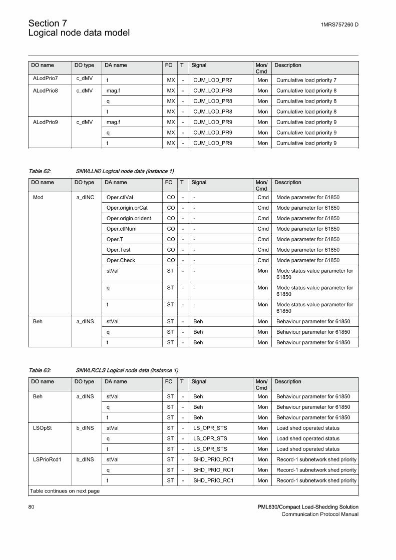
DO name DO type DA name FC T Signal Mon/Cmd
Description
ALodPrio7 c_dMV t MX - CUM_LOD_PR7 Mon Cumulative load priority 7
ALodPrio8 c_dMV mag.f MX - CUM_LOD_PR8 Mon Cumulative load priority 8
q MX - CUM_LOD_PR8 Mon Cumulative load priority 8
t MX - CUM_LOD_PR8 Mon Cumulative load priority 8
ALodPrio9 c_dMV mag.f MX - CUM_LOD_PR9 Mon Cumulative load priority 9
q MX - CUM_LOD_PR9 Mon Cumulative load priority 9
t MX - CUM_LOD_PR9 Mon Cumulative load priority 9
Table 62: SNWLLN0 Logical node data (instance 1)
DO name DO type DA name FC T Signal Mon/Cmd
Description
Mod a_dINC Oper.ctlVal CO - - Cmd Mode parameter for 61850
Oper.origin.orCat CO - - Cmd Mode parameter for 61850
Oper.origin.orIdent CO - - Cmd Mode parameter for 61850
Oper.ctlNum CO - - Cmd Mode parameter for 61850
Oper.T CO - - Cmd Mode parameter for 61850
Oper.Test CO - - Cmd Mode parameter for 61850
Oper.Check CO - - Cmd Mode parameter for 61850
stVal ST - - Mon Mode status value parameter for61850
q ST - - Mon Mode status value parameter for61850
t ST - - Mon Mode status value parameter for61850
Beh a_dINS stVal ST - Beh Mon Behaviour parameter for 61850
q ST - Beh Mon Behaviour parameter for 61850
t ST - Beh Mon Behaviour parameter for 61850
Table 63: SNWLRCLS Logical node data (instance 1)
DO name DO type DA name FC T Signal Mon/Cmd
Description
Beh a_dINS stVal ST - Beh Mon Behaviour parameter for 61850
q ST - Beh Mon Behaviour parameter for 61850
t ST - Beh Mon Behaviour parameter for 61850
LSOpSt b_dINS stVal ST - LS_OPR_STS Mon Load shed operated status
q ST - LS_OPR_STS Mon Load shed operated status
t ST - LS_OPR_STS Mon Load shed operated status
LSPrioRcd1 b_dINS stVal ST - SHD_PRIO_RC1 Mon Record-1 subnetwork shed priority
q ST - SHD_PRIO_RC1 Mon Record-1 subnetwork shed priority
t ST - SHD_PRIO_RC1 Mon Record-1 subnetwork shed priority
Table continues on next page
Section 7 1MRS757260 DLogical node data model
80 PML630/Compact Load-Shedding SolutionCommunication Protocol Manual
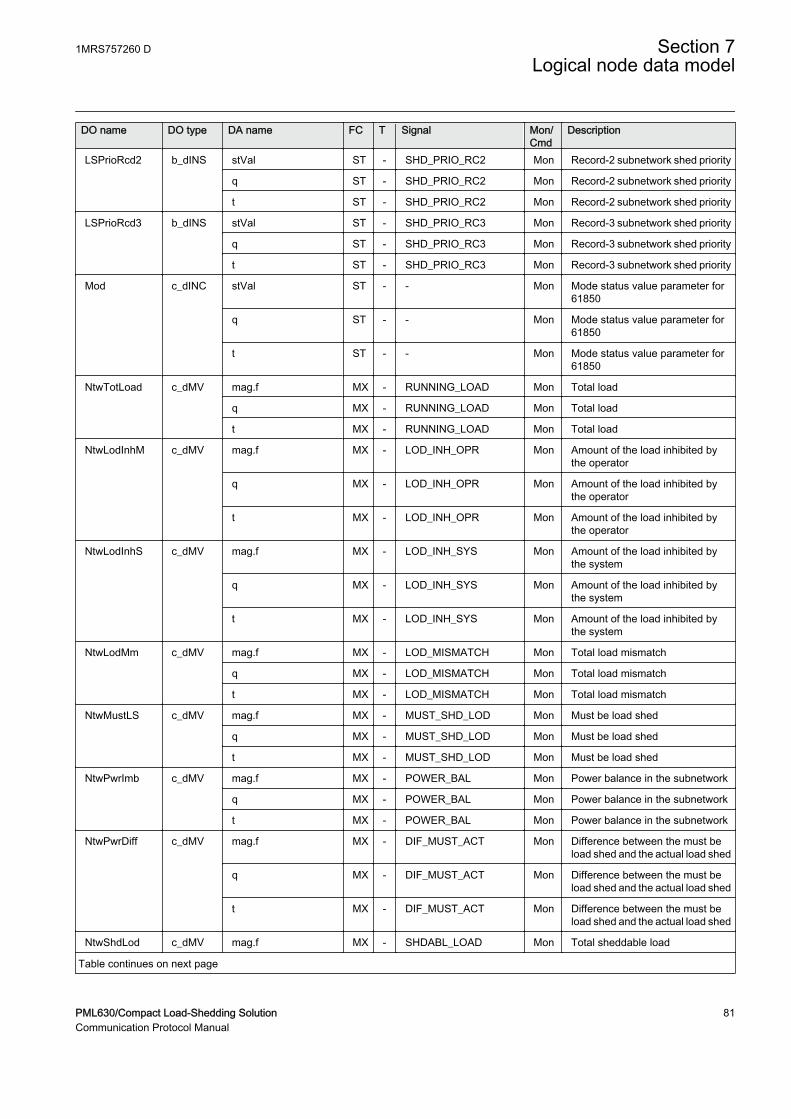
DO name DO type DA name FC T Signal Mon/Cmd
Description
LSPrioRcd2 b_dINS stVal ST - SHD_PRIO_RC2 Mon Record-2 subnetwork shed priority
q ST - SHD_PRIO_RC2 Mon Record-2 subnetwork shed priority
t ST - SHD_PRIO_RC2 Mon Record-2 subnetwork shed priority
LSPrioRcd3 b_dINS stVal ST - SHD_PRIO_RC3 Mon Record-3 subnetwork shed priority
q ST - SHD_PRIO_RC3 Mon Record-3 subnetwork shed priority
t ST - SHD_PRIO_RC3 Mon Record-3 subnetwork shed priority
Mod c_dINC stVal ST - - Mon Mode status value parameter for61850
q ST - - Mon Mode status value parameter for61850
t ST - - Mon Mode status value parameter for61850
NtwTotLoad c_dMV mag.f MX - RUNNING_LOAD Mon Total load
q MX - RUNNING_LOAD Mon Total load
t MX - RUNNING_LOAD Mon Total load
NtwLodInhM c_dMV mag.f MX - LOD_INH_OPR Mon Amount of the load inhibited bythe operator
q MX - LOD_INH_OPR Mon Amount of the load inhibited bythe operator
t MX - LOD_INH_OPR Mon Amount of the load inhibited bythe operator
NtwLodInhS c_dMV mag.f MX - LOD_INH_SYS Mon Amount of the load inhibited bythe system
q MX - LOD_INH_SYS Mon Amount of the load inhibited bythe system
t MX - LOD_INH_SYS Mon Amount of the load inhibited bythe system
NtwLodMm c_dMV mag.f MX - LOD_MISMATCH Mon Total load mismatch
q MX - LOD_MISMATCH Mon Total load mismatch
t MX - LOD_MISMATCH Mon Total load mismatch
NtwMustLS c_dMV mag.f MX - MUST_SHD_LOD Mon Must be load shed
q MX - MUST_SHD_LOD Mon Must be load shed
t MX - MUST_SHD_LOD Mon Must be load shed
NtwPwrImb c_dMV mag.f MX - POWER_BAL Mon Power balance in the subnetwork
q MX - POWER_BAL Mon Power balance in the subnetwork
t MX - POWER_BAL Mon Power balance in the subnetwork
NtwPwrDiff c_dMV mag.f MX - DIF_MUST_ACT Mon Difference between the must beload shed and the actual load shed
q MX - DIF_MUST_ACT Mon Difference between the must beload shed and the actual load shed
t MX - DIF_MUST_ACT Mon Difference between the must beload shed and the actual load shed
NtwShdLod c_dMV mag.f MX - SHDABL_LOAD Mon Total sheddable load
Table continues on next page
1MRS757260 D Section 7Logical node data model
PML630/Compact Load-Shedding Solution 81Communication Protocol Manual

DO name DO type DA name FC T Signal Mon/Cmd
Description
NtwShdLod c_dMV q MX - SHDABL_LOAD Mon Total sheddable load
t MX - SHDABL_LOAD Mon Total sheddable load
NtwAvaPwr c_dMV mag.f MX - AVA_POWER Mon Total available power
q MX - AVA_POWER Mon Total available power
t MX - AVA_POWER Mon Total available power
ManLSPwr c_dMV mag.f MX - MAN_SHD_POW Mon Manual load-shed power settings
q MX - MAN_SHD_POW Mon Manual load-shed power settings
t MX - MAN_SHD_POW Mon Manual load-shed power settings
EffPwrImb c_dMV mag.f MX - EFF_POW_BAL Mon Effective power balance in thesubnetwork
q MX - EFF_POW_BAL Mon Effective power balance in thesubnetwork
t MX - EFF_POW_BAL Mon Effective power balance in thesubnetwork
NtwALodShd c_dMV mag.f MX - ACT_SHD_LOD Mon Actual shed load
q MX - ACT_SHD_LOD Mon Actual shed load
t MX - ACT_SHD_LOD Mon Actual shed load
LsOp c_dSPS stVal ST - LS_OPERATE Mon Load-shed operate
q ST - LS_OPERATE Mon Load-shed operate
t ST - LS_OPERATE Mon Load-shed operate
LSBlkSt c_dSPS stVal ST - LS_BLOCK Mon Load-shed block
q ST - LS_BLOCK Mon Load-shed block
t ST - LS_BLOCK Mon Load-shed block
NtwActSt c_dSPS stVal ST - SN_ACTIVE Mon Subnetwork active status
q ST - SN_ACTIVE Mon Subnetwork active status
t ST - SN_ACTIVE Mon Subnetwork active status
SlwLSBlkSt c_dSPS stVal ST - SLS_TRG_INH Mon Slow load-shed trigger inhibit
q ST - SLS_TRG_INH Mon Slow load-shed trigger inhibit
t ST - SLS_TRG_INH Mon Slow load-shed trigger inhibit
NtwEnaSt c_dSPS stVal ST - DISABLE_LS Mon Load shed disable
q ST - DISABLE_LS Mon Load shed disable
t ST - DISABLE_LS Mon Load shed disable
NgPwrBalSt c_dSPS stVal ST - NEG_POW_BAL Mon Negative power balance status
q ST - NEG_POW_BAL Mon Negative power balance status
t ST - NEG_POW_BAL Mon Negative power balance status
7.4.8 Output interface function for peer network data PPLSGGIO
LN type LN prefix LN class Function block name
PPLSLLN0 instance 1 (revision 0) - LLN0 PPLSGGIO
Section 7 1MRS757260 DLogical node data model
82 PML630/Compact Load-Shedding SolutionCommunication Protocol Manual
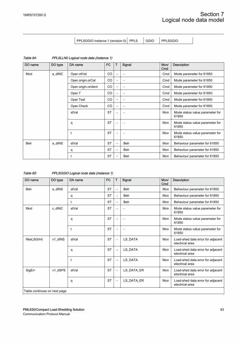
PPLSGGIO instance 1 (revision 0) PPLS GGIO PPLSGGIO
Table 64: PPLSLLN0 Logical node data (instance 1)
DO name DO type DA name FC T Signal Mon/Cmd
Description
Mod a_dINC Oper.ctlVal CO - - Cmd Mode parameter for 61850
Oper.origin.orCat CO - - Cmd Mode parameter for 61850
Oper.origin.orIdent CO - - Cmd Mode parameter for 61850
Oper.T CO - - Cmd Mode parameter for 61850
Oper.Test CO - - Cmd Mode parameter for 61850
Oper.Check CO - - Cmd Mode parameter for 61850
stVal ST - - Mon Mode status value parameter for61850
q ST - - Mon Mode status value parameter for61850
t ST - - Mon Mode status value parameter for61850
Beh a_dINS stVal ST - Beh Mon Behaviour parameter for 61850
q ST - Beh Mon Behaviour parameter for 61850
t ST - Beh Mon Behaviour parameter for 61850
Table 65: PPLSGGIO Logical node data (instance 1)
DO name DO type DA name FC T Signal Mon/Cmd
Description
Beh a_dINS stVal ST - Beh Mon Behaviour parameter for 61850
q ST - Beh Mon Behaviour parameter for 61850
t ST - Beh Mon Behaviour parameter for 61850
Mod c_dINC stVal ST - - Mon Mode status value parameter for61850
q ST - - Mon Mode status value parameter for61850
t ST - - Mon Mode status value parameter for61850
NtwLSGrInt v1_dINS stVal ST - LS_DATA Mon Load-shed data error for adjacentelectrical area
q ST - LS_DATA Mon Load-shed data error for adjacentelectrical area
t ST - LS_DATA Mon Load-shed data error for adjacentelectrical area
SigErr v1_dSPS stVal ST - LS_DATA_ER Mon Load-shed data error for adjacentelectrical area
q ST - LS_DATA_ER Mon Load-shed data error for adjacentelectrical area
Table continues on next page
1MRS757260 D Section 7Logical node data model
PML630/Compact Load-Shedding Solution 83Communication Protocol Manual

DO name DO type DA name FC T Signal Mon/Cmd
Description
SigErr v1_dSPS t ST - LS_DATA_ER Mon Load-shed data error for adjacentelectrical area
RxCBSt v1_dSPS stVal ST - PEER_CB_STS Mon CB status of the adjacentelectrical area
q ST - PEER_CB_STS Mon CB status of the adjacentelectrical area
t ST - PEER_CB_STS Mon CB status of the adjacentelectrical area
RxSigErr v1_dSPS stVal ST - PEER_DATA_ER Mon Data error of the adjacentelectrical area
q ST - PEER_DATA_ER Mon Data error of the adjacentelectrical area
t ST - PEER_DATA_ER Mon Data error of the adjacentelectrical area
RxCBBlk v1_dSPS stVal ST - PEER_SRC_BLK Mon Connectivity and CB block statusof the adjacent electrical area
q ST - PEER_SRC_BLK Mon Connectivity and CB block statusof the adjacent electrical area
t ST - PEER_SRC_BLK Mon Connectivity and CB block statusof the adjacent electrical area
RxNtwBlk v1_dSPS stVal ST - PEER_SN_BLK Mon Subnetwork LS block status ofthe adjacent electrical area
q ST - PEER_SN_BLK Mon Subnetwork LS block status ofthe adjacent electrical area
t ST - PEER_SN_BLK Mon Subnetwork LS block status ofthe adjacent electrical area
RxSpRsvPwr v2_dMV mag.f MX - PEER_SP_RSV Mon Spinning reserve of the adjacentelectrical area
q MX - PEER_SP_RSV Mon Spinning reserve of the adjacentelectrical area
t MX - PEER_SP_RSV Mon Spinning reserve of the adjacentelectrical area
RxLSPwr v2_dMV mag.f MX - PEER_MUST_LS Mon Must shed power extended fromthe adjacent electrical area
q MX - PEER_MUST_LS Mon Must shed power extended fromthe adjacent electrical area
t MX - PEER_MUST_LS Mon Must shed power extended fromthe adjacent electrical area
7.5 Logical node for disturbance recorder function
7.5.1 Disturbance report DRRDRE
LN type LN prefix LN class Function block name
DRRDRE (revision 0) DR RDRE DRRDRE
Section 7 1MRS757260 DLogical node data model
84 PML630/Compact Load-Shedding SolutionCommunication Protocol Manual
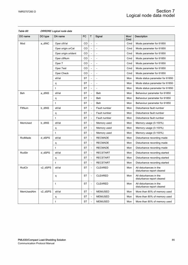
Table 66: DRRDRE Logical node data
DO name DO type DA name FC T Signal Mon/Cmd
Description
Mod a_dINC Oper.ctlVal CO - - Cmd Mode parameter for 61850
Oper.origin.orCat CO - - Cmd Mode parameter for 61850
Oper.origin.orIdent CO - - Cmd Mode parameter for 61850
Oper.ctlNum CO - - Cmd Mode parameter for 61850
Oper.T CO - - Cmd Mode parameter for 61850
Oper.Test CO - - Cmd Mode parameter for 61850
Oper.Check CO - - Cmd Mode parameter for 61850
stVal ST - - Mon Mode status parameter for 61850
q ST - - Mon Mode status parameter for 61850
t ST - - Mon Mode status parameter for 61850
Beh a_dINS stVal ST - Beh Mon Behaviour parameter for 61850
q ST - Beh Mon Behaviour parameter for 61850
t ST - Beh Mon Behaviour parameter for 61850
FltNum b_dINS stVal ST - Fault number Mon Disturbance fault number
q ST - Fault number Mon Disturbance fault number
t ST - Fault number Mon Disturbance fault number
MemUsed b_dINS stVal ST - Memory used Mon Memory usage (0-100%)
q ST - Memory used Mon Memory usage (0-100%)
t ST - Memory used Mon Memory usage (0-100%)
RcdMade d_dSPS stVal ST - RECMADE Mon Disturbance recording made
q ST - RECMADE Mon Disturbance recording made
t ST - RECMADE Mon Disturbance recording made
RcdStr d_dSPS stVal ST - RECSTART Mon Disturbance recording started
q ST - RECSTART Mon Disturbance recording started
t ST - RECSTART Mon Disturbance recording started
RcdClr v2_dSPS stVal ST - CLEARED Mon All disturbances in thedisturbance report cleared
q ST - CLEARED Mon All disturbances in thedisturbance report cleared
t ST - CLEARED Mon All disturbances in thedisturbance report cleared
MemUsedAlm v2_dSPS stVal ST - MEMUSED Mon More than 80% of memory used
q ST - MEMUSED Mon More than 80% of memory used
t ST - MEMUSED Mon More than 80% of memory used
1MRS757260 D Section 7Logical node data model
PML630/Compact Load-Shedding Solution 85Communication Protocol Manual
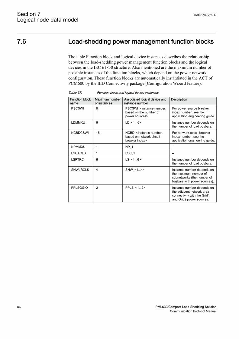
7.6 Load-shedding power management function blocks
The table Function block and logical device instances describes the relationshipbetween the load-shedding power management function blocks and the logicaldevices in the IEC 61850 structure. Also mentioned are the maximum number ofpossible instances of the function blocks, which depend on the power networkconfiguration. These function blocks are automatically instantiated in the ACT ofPCM600 by the IED Connectivity package (Configuration Wizard feature).
Table 67: Function block and logical device instances
Function blockname
Maximum numberof instances
Associated logical device andinstance number
Description
PSCSWI 8 PSCSWI_<instance number,based on the number ofpower sources>
For power source breakerindex number, see theapplication engineering guide.
LDMMXU 6 LD_<1...6> Instance number depends onthe number of load busbars.
NCBDCSWI 15 NCBD_<instance number,based on network circuitbreaker index>
For network circuit breakerindex number, see theapplication engineering guide.
NPMMXU 1 NP_1 –
LSCACLS 1 LSC_1 –
LSPTRC 6 LS_<1...6> Instance number depends onthe number of load busbars.
SNWLRCLS 4 SNW_<1...4> Instance number depends onthe maximum number ofsubnetworks (the number ofbusbars with power sources).
PPLSGGIO 2 PPLS_<1...2> Instance number depends onthe adjacent network areaconnectivity with the Grid1and Grid2 power sources.
Section 7 1MRS757260 DLogical node data model
86 PML630/Compact Load-Shedding SolutionCommunication Protocol Manual
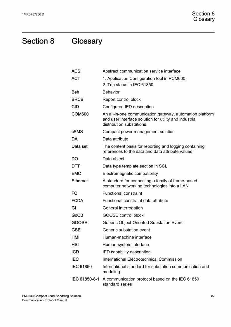
Section 8 Glossary
ACSI Abstract communication service interfaceACT 1. Application Configuration tool in PCM600
2. Trip status in IEC 61850Beh BehaviorBRCB Report control blockCID Configured IED descriptionCOM600 An all-in-one communication gateway, automation platform
and user interface solution for utility and industrialdistribution substations
cPMS Compact power management solutionDA Data attributeData set The content basis for reporting and logging containing
references to the data and data attribute valuesDO Data objectDTT Data type template section in SCLEMC Electromagnetic compatibilityEthernet A standard for connecting a family of frame-based
computer networking technologies into a LANFC Functional constraintFCDA Functional constraint data attributeGI General interrogationGoCB GOOSE control blockGOOSE Generic Object-Oriented Substation EventGSE Generic substation eventHMI Human-machine interfaceHSI Human-system interfaceICD IED capability descriptionIEC International Electrotechnical CommissionIEC 61850 International standard for substation communication and
modelingIEC 61850-8-1 A communication protocol based on the IEC 61850
standard series
1MRS757260 D Section 8Glossary
PML630/Compact Load-Shedding Solution 87Communication Protocol Manual
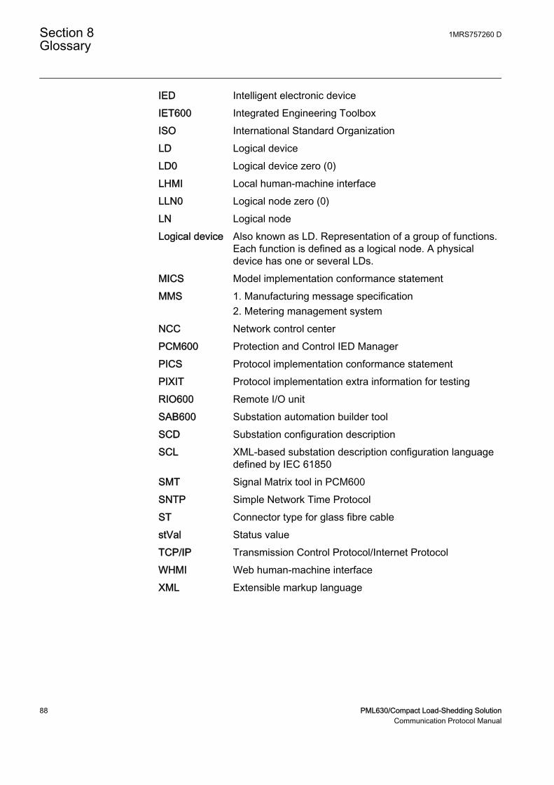
IED Intelligent electronic deviceIET600 Integrated Engineering ToolboxISO International Standard OrganizationLD Logical deviceLD0 Logical device zero (0)LHMI Local human-machine interfaceLLN0 Logical node zero (0)LN Logical nodeLogical device Also known as LD. Representation of a group of functions.
Each function is defined as a logical node. A physicaldevice has one or several LDs.
MICS Model implementation conformance statementMMS 1. Manufacturing message specification
2. Metering management systemNCC Network control centerPCM600 Protection and Control IED ManagerPICS Protocol implementation conformance statementPIXIT Protocol implementation extra information for testingRIO600 Remote I/O unitSAB600 Substation automation builder toolSCD Substation configuration descriptionSCL XML-based substation description configuration language
defined by IEC 61850SMT Signal Matrix tool in PCM600SNTP Simple Network Time ProtocolST Connector type for glass fibre cablestVal Status valueTCP/IP Transmission Control Protocol/Internet ProtocolWHMI Web human-machine interfaceXML Extensible markup language
Section 8 1MRS757260 DGlossary
88 PML630/Compact Load-Shedding SolutionCommunication Protocol Manual

89
Contact us
ABB OyMedium Voltage Products,Distribution AutomationP.O. Box 699FI-65101 VAASA, FinlandPhone +358 10 22 11Fax +358 10 22 41094
www.abb.com/substationautomation
1MR
S75
7260
D©
Cop
yrig
ht 2
013
AB
B. A
ll rig
hts
rese
rved
.