Polyphase Systems 23
37
Polyphase Systems 23.1 INTRODUCTION An ac generator designed to develop a single sinusoidal voltage for each rotation of the shaft (rotor) is referred to as a single-phase ac generator. If the number of coils on the rotor is in- creased in a specified manner, the result is a polyphase ac generator, which develops more than one ac phase voltage per rotation of the rotor. In this chapter, the three-phase system is discussed in detail since it is the most frequently used for power transmission. In general, three-phase systems are preferred over single-phase systems for the transmis- sion of power for many reasons, including the following: 1. Thinner conductors can be used to transmit the same kVA at the same voltage, which reduces the amount of copper required (typically about 25% less) and in turn reduces construction and maintenance costs. 2. The lighter lines are easier to install, and the supporting structures can be less massive and farther apart. 3. Three-phase equipment and motors have preferred running and starting characteristics compared to single-phase systems because of a more even flow of power to the trans- ducer than can be delivered with a single-phase supply. 4. In general, most larger motors are three phase because they are essentially self-starting and do not require a special design or additional starting circuitry. The frequency generated is determined by the number of poles on the rotor (the rotating part of the generator) and the speed with which the shaft is turned. In the United States, the line frequency is 60 Hz, whereas in Europe the chosen standard is 50 Hz. Both frequencies were chosen primarily because they can be generated by a relatively efficient and stable me- chanical design that is sensitive to the size of the generating systems and the demand that must be met during peak periods. On aircraft and ships, the demand levels permit the use of a 400 Hz line frequency. • Become familiar with the operation of a three- phase generator and the magnitude and phase relationship between the three phase voltages. • Be able to calculate the voltages and currents for a three-phase Y-connected generator and Y-connected load. • Understand the significance of the phase sequence on the generated voltages of a three-phase Y-connected or -connected generator. • Be able to calculate the voltages and currents for a three-phase -connected generator and -connected load. • Understand how to calculate the real, reactive, and apparent power to all the elements of a Y- or -connected load and be able to measure the power to the load. 23 Objectives 23 Polyphase Systems
Transcript of Polyphase Systems 23
Polyphase Systems
23.1 INTRODUCTION
An ac generator designed to develop a single sinusoidal voltage for each rotation of the shaft(rotor) is referred to as a single-phase ac generator. If the number of coils on the rotor is in-creased in a specified manner, the result is a polyphase ac generator, which develops morethan one ac phase voltage per rotation of the rotor. In this chapter, the three-phase system isdiscussed in detail since it is the most frequently used for power transmission.
In general, three-phase systems are preferred over single-phase systems for the transmis-sion of power for many reasons, including the following:
1. Thinner conductors can be used to transmit the same kVA at the same voltage, whichreduces the amount of copper required (typically about 25% less) and in turn reducesconstruction and maintenance costs.
2. The lighter lines are easier to install, and the supporting structures can be less massiveand farther apart.
3. Three-phase equipment and motors have preferred running and starting characteristicscompared to single-phase systems because of a more even flow of power to the trans-ducer than can be delivered with a single-phase supply.
4. In general, most larger motors are three phase because they are essentially self-startingand do not require a special design or additional starting circuitry.
The frequency generated is determined by the number of poles on the rotor (the rotatingpart of the generator) and the speed with which the shaft is turned. In the United States, theline frequency is 60 Hz, whereas in Europe the chosen standard is 50 Hz. Both frequencieswere chosen primarily because they can be generated by a relatively efficient and stable me-chanical design that is sensitive to the size of the generating systems and the demand that mustbe met during peak periods. On aircraft and ships, the demand levels permit the use of a 400 Hzline frequency.
• Become familiar with the operation of a three-
phase generator and the magnitude and phase
relationship between the three phase voltages.
• Be able to calculate the voltages and currents for a
three-phase Y-connected generator and
Y-connected load.
• Understand the significance of the phase sequence
on the generated voltages of a three-phase
Y-connected or �-connected generator.
• Be able to calculate the voltages and currents for a
three-phase �-connected generator and
�-connected load.
• Understand how to calculate the real, reactive,
and apparent power to all the elements of a Y- or
�-connected load and be able to measure the
power to the load.
23Objectives
23Polyphase Systems
boy30444_ch23.qxd 3/24/06 3:36 PM Page 1029

1030 ⏐⏐⏐ POLYPHASE SYSTEMS
The three-phase system is used by almost all commercial electric gen-erators. This does not mean that single-phase and two-phase generatingsystems are obsolete. Most small emergency generators, such as thegasoline type, are one-phase generating systems. The two-phase systemis commonly used in servomechanisms, which are self-correcting controlsystems capable of detecting and adjusting their own operation. Servo-mechanisms are used in ships and aircraft to keep them on course auto-matically, or, in simpler devices such as a thermostatic circuit, to regulateheat output. In many cases, however, where single-phase and two-phaseinputs are required, they are supplied by one and two phases of a three-phase generating system rather than generated independently.
The number of phase voltages that can be produced by a polyphasegenerator is not limited to three. Any number of phases can be obtainedby spacing the windings for each phase at the proper angular positionaround the stator. Some electrical systems operate more efficiently ifmore than three phases are used. One such system involves the processof rectification, which is used to convert an alternating output to one hav-ing an average, or dc, value. The greater the number of phases, thesmoother the dc output of the system.
23.2 THREE-PHASE GENERATOR
The three-phase generator in Fig. 23.1(a) has three induction coils placed120° apart on the stator, as shown symbolically by Fig. 23.1(b). Since thethree coils have an equal number of turns, and each coil rotates with thesame angular velocity, the voltage induced across each coil has the samepeak value, shape, and frequency. As the shaft of the generator is turnedby some external means, the induced voltages eAN, eBN, and eCN are gen-erated simultaneously, as shown in Fig. 23.2. Note the 120° phase shiftbetween waveforms and the similarities in appearance of the three sinu-soidal functions.
A
(a)
BC
N
120°
A
BC
+
–
eAN
N
–
N
N
120°
120°
eBN
eCN +
+
–
(b)
FIG. 23.1
(a) Three-phase generator; (b) induced voltages of a three-phase generator.
In particular, note that
at any instant of time, the algebraic sum of the three phase voltagesof a three-phase generator is zero.
This is shown at vt � 0 in Fig. 23.2, where it is also evident that whenone induced voltage is zero, the other two are 86.6% of their positive ornegative maximums. In addition, when any two are equal in magnitude
boy30444_ch23.qxd 3/24/06 3:36 PM Page 1030

Y-CONNECTED GENERATOR ⏐⏐⏐ 1031
0.866 Em(CN)
0
60°0.866 Em(BN)
120° 120°
p2
p
eAN
0.5 Em(CN)
0.5 Em(CN)
eBN eCN
32p
2p 52p
3p 72p
4p qt
e
FIG. 23.2
Phase voltages of a three-phase generator.
and sign (at 0.5Em), the remaining induced voltage has the opposite po-larity and a peak value.
The sinusoidal expression for each of the induced voltages in Fig.23.2 is
(23.1)
The phasor diagram of the induced voltages is shown in Fig. 23.3,where the effective value of each is determined by
EAN � 0.707Em(AN)
EBN � 0.707Em(BN)
ECN � 0.707Em(CN)
and EAN � EAN �0°EBN � EBN ��120°ECN � ECN ��120°
By rearranging the phasors as shown in Fig. 23.4 and applying a lawof vectors which states that the vector sum of any number of vectorsdrawn such that the “head” of one is connected to the “tail” of the next,and that the head of the last vector is connected to the tail of the first iszero, we can conclude that the phasor sum of the phase voltages in athree-phase system is zero. That is,
(23.2)
23.3 Y-CONNECTED GENERATOR
If the three terminals denoted N in Fig. 23.1(b) are connected together,the generator is referred to as a Y-connected three-phase generator
EAN � EBN � ECN � 0
eAN � Em1AN2 sin vt
eBN � Em1BN2 sin1vt � 120° 2eCN � Em1CN2 sin1vt � 240° 2 � Em1CN2 sin1vt � 120° 2
120°
120°
120°
ECN
EAN
EBN
FIG. 23.3
Phasor diagram for the phase voltages of a three-phase generator.
EBN
EAN
ECN
FIG. 23.4
Demonstrating that the vector sum of the phasevoltages of a three-phase generator is zero.
boy30444_ch23.qxd 3/24/06 3:37 PM Page 1031

1032 ⏐⏐⏐ POLYPHASE SYSTEMS
Line
LOAD
IL
Line
IL
Line
IL
Neutral
Ifg
+
EAN
–
A
N
Ifg
+ECN
–
C B
Ifg
EBN+
–
FIG. 23.5
Y-connected generator.
(Fig. 23.5). As indicated in Fig. 23.5, the Y is inverted for ease of nota-tion and for clarity. The point at which all the terminals are connected iscalled the neutral point. If a conductor is not attached from this point tothe load, the system is called a Y-connected, three-phase, three-wire gen-erator. If the neutral is connected, the system is a Y-connected, three-phase, four-wire generator. The function of the neutral will be discussedin detail when we consider the load circuit.
The three conductors connected from A, B, and C to the load are calledlines. For the Y-connected system, it should be obvious from Fig. 23.5that the line current equals the phase current for each phase; that is,
(23.3)
where f is used to denote a phase quantity and g is a generator parameter.The voltage from one line to another is called a line voltage. On the
phasor diagram (Fig. 23.6) it is the phasor drawn from the end of onephase to another in the counterclockwise direction.
Applying Kirchhoff’s voltage law around the indicated loop in Fig.23.6, we obtain
EAB � EAN � EBN � 0
or EAB � EAN � EBN � EAN � ENB
The phasor diagram is redrawn to find EAB as shown in Fig. 23.7. Since eachphase voltage, when reversed (ENB), bisects the other two, � � 60°. The an-gle b is 30° since a line drawn from opposite ends of a rhombus divides inhalf both the angle of origin and the opposite angle. Lines drawn betweenopposite corners of a rhombus also bisect each other at right angles.
The length x is
and EAB � 2x � 12 2 13
2EAN � 13EAN
x � EAN cos 30° �13
2 EAN
IL � Ifg
(phase voltage)
+EAN
– A
N
+
ECN
–
C
B
EBN
+–
EBC
(line voltage)EAB
ECA
FIG. 23.6
Line and phase voltages of the Y-connected three-phase generator.
120°
120°
ECN
EAN
EBN
α = 60°α
α = 60°α
ENB
EAB
β = 30°x
x
FIG. 23.7
Determining a line voltage for a three-phasegenerator.
boy30444_ch23.qxd 3/24/06 3:37 PM Page 1032

PHASE SEQUENCE (Y-CONNECTED GENERATOR) ⏐⏐⏐ 1033
Noting from the phasor diagram that u of EAB � b � 30°, the result is
and
In words, the magnitude of the line voltage of a Y-connected generatoris times the phase voltage:
(23.4)
with the phase angle between any line voltage and the nearest phase volt-age at 30°.
In sinusoidal notation,
and
The phasor diagram of the line and phase voltages is shown in Fig. 23.8.If the phasors representing the line voltages in Fig. 23.8(a) are rearrangedslightly, they will form a closed loop [Fig. 23.8(b)]. Therefore, we canconclude that the sum of the line voltages is also zero; that is,
(23.5)EAB � ECA � EBC � 0
eBC � 12EBC sin1vt � 270° 2 eCA � 12ECA sin1vt � 150° 2 eAB � 12EAB sin1vt � 30° 2
EL � 13Ef
13
EBC � 13EBN �270°
ECA � 13ECN �150°
EAB � EAB �30° � 13EAN �30°
Fixed point P
EANA
N
ECN
C
B
EBN
Rotation
FIG. 23.9
Determining the phase sequence from the phasevoltages of a three-phase generator.
(b)
EAB
EBC
ECA
120°
120°
120°
ECN
EAN
EBN
30°
30°EABECA
EBC
30°
(a)
FIG. 23.8
(a) Phasor diagram of the line and phase voltages of a three-phase generator;(b) demonstrating that the vector sum of the line voltages of a three-phase
system is zero.
23.4 PHASE SEQUENCE (Y-CONNECTED GENERATOR)
The phase sequence can be determined by the order in which the phasorsrepresenting the phase voltages pass through a fixed point on the phasordiagram if the phasors are rotated in a counterclockwise direction. For ex-ample, in Fig. 23.9 the phase sequence is ABC. However, since the fixedpoint can be chosen anywhere on the phasor diagram, the sequence can
boy30444_ch23.qxd 3/24/06 3:37 PM Page 1033

1034 ⏐⏐⏐ POLYPHASE SYSTEMS
also be written as BCA or CAB. The phase sequence is quite important inthe three-phase distribution of power. In a three-phase motor, for exam-ple, if two phase voltages are interchanged, the sequence will change, andthe direction of rotation of the motor will be reversed. Other effects willbe described when we consider the loaded three-phase system.
The phase sequence can also be described in terms of the line voltages.Drawing the line voltages on a phasor diagram in Fig. 23.10, we are ableto determine the phase sequence by again rotating the phasors in thecounterclockwise direction. In this case, however, the sequence can bedetermined by noting the order of the passing first or second subscripts.In the system in Fig. 23.10, for example, the phase sequence of the firstsubscripts passing point P is ABC, and the phase sequence of the secondsubscripts is BCA. But we know that BCA is equivalent to ABC, so the se-quence is the same for each. Note that the phase sequence is the same asthat of the phase voltages described in Fig. 23.9.
If the sequence is given, the phasor diagram can be drawn by simplypicking a reference voltage, placing it on the reference axis, and thendrawing the other voltages at the proper angular position. For a sequenceof ACB, for example, we might choose EAB to be the reference [Fig.23.11(a)] if we wanted the phasor diagram of the line voltages, or EAN forthe phase voltages [Fig. 23.11(b)]. For the sequence indicated, the pha-sor diagrams would be as in Fig. 23.11. In phasor notation,
Phase
voltages
•EAN � EAN �0°� 1reference 2ECN � ECN ��120°
EBN � EBN ��120°
Line
voltages
•EAB � EAB �0°� 1reference 2ECA � ECA ��120°
EBC � EBC ��120°
P
EABA
ECA
C
B
EBC
Rotation
FIG. 23.10
Determining the phase sequence from the linevoltages of a three-phase generator.
P
EAB
A
EBC
B
C
ECA
ACB
(a)
P
EAN
A
EBN
B
C
ECN
ACB
(b)
FIG. 23.11
Drawing the phasor diagram from the phase sequence.
boy30444_ch23.qxd 3/24/06 3:37 PM Page 1034
Y-CONNECTED GENERATOR WITH A Y-CONNECTED LOAD ⏐⏐⏐ 1035
IL
IL
EL
Ifg
+
–
A
N
Ifg
+
–
C B
Ifg
+
–Ef
Ef
EL
ILc
EL
IfL
IN
aIfL
Ef Vf
+
–
n
IfL
bVf Vf
+
–
+
–
Z1
Z3 Z2
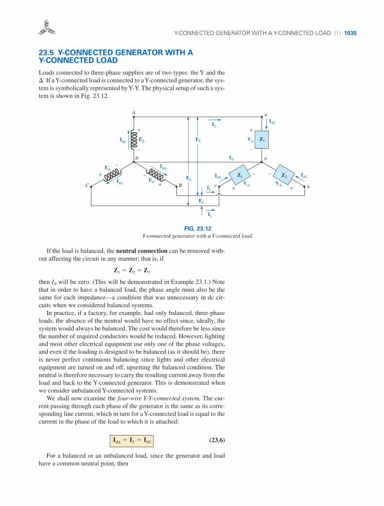
FIG. 23.12
Y-connected generator with a Y-connected load.
23.5 Y-CONNECTED GENERATOR WITH A Y-CONNECTED LOAD
Loads connected to three-phase supplies are of two types: the Y and the�. If a Y-connected load is connected to a Y-connected generator, the sys-tem is symbolically represented by Y-Y. The physical setup of such a sys-tem is shown in Fig. 23.12.
If the load is balanced, the neutral connection can be removed with-out affecting the circuit in any manner; that is, if
Z1 � Z2 � Z3
then IN will be zero. (This will be demonstrated in Example 23.1.) Notethat in order to have a balanced load, the phase angle must also be thesame for each impedance—a condition that was unnecessary in dc cir-cuits when we considered balanced systems.
In practice, if a factory, for example, had only balanced, three-phaseloads, the absence of the neutral would have no effect since, ideally, thesystem would always be balanced. The cost would therefore be less sincethe number of required conductors would be reduced. However, lightingand most other electrical equipment use only one of the phase voltages,and even if the loading is designed to be balanced (as it should be), thereis never perfect continuous balancing since lights and other electricalequipment are turned on and off, upsetting the balanced condition. Theneutral is therefore necessary to carry the resulting current away from theload and back to the Y-connected generator. This is demonstrated whenwe consider unbalanced Y-connected systems.
We shall now examine the four-wire Y-Y-connected system. The cur-rent passing through each phase of the generator is the same as its corre-sponding line current, which in turn for a Y-connected load is equal to thecurrent in the phase of the load to which it is attached:
(23.6)
For a balanced or an unbalanced load, since the generator and loadhave a common neutral point, then
Ifg � IL � IfL
boy30444_ch23.qxd 3/24/06 3:37 PM Page 1035

1036 ⏐⏐⏐ POLYPHASE SYSTEMS
(23.7)
In addition, since IfL � Vf /Zf, the magnitude of the current in eachphase is equal for a balanced load and unequal for an unbalanced load.Recall that for the Y-connected generator, the magnitude of the line volt-age is equal to times the phase voltage. This same relationship canbe applied to a balanced or an unbalanced four-wire Y-connected load:
(23.8)
For a voltage drop across a load element, the first subscript refers tothat terminal through which the current enters the load element, and thesecond subscript refers to the terminal from which the current leaves. Inother words, the first subscript is, by definition, positive with respect tothe second for a voltage drop. Note Fig. 23.13, in which the standard dou-ble subscripts for a source of voltage and a voltage drop are indicated.
EXAMPLE 23.1 The phase sequence of the Y-connected generator inFig. 23.13 is ABC.
a. Find the phase angles u2 and u3.b. Find the magnitude of the line voltages.c. Find the line currents.d. Verify that, since the load is balanced, IN � 0.
EL � 13Vf
13
Vf � Ef
A
+
–
120 V 0°EAN
120 V θ3θ
ECN EBN+
–
+
–N
C B
a
+
–
3 �Ian
+
–
+
– n
c b
Van
4 �
4 � Vbn
3 �
Vcn
3 �
Icn Ibn
IAa
EAB
IN
IBb
ECA
ICcEBC
4 � Balancedload
120 V θ2θ
FIG. 23.13
Example 23.1.
Solutions:
a. For an ABC phase sequence,
u2 � �120° and u3 � �120°
b. Therefore,
EAB � EBC � ECA � 208 V
c. Vf � Ef . Therefore,
� 24 A ��53.13°
IfL � Ian �Van
Zan
�120 V �0°
3 � � j 4 ��
120 V �0°
5 � �53.13°
Van � EAN���Vbn � EBN���Vcn � ECN
EL � 13Ef � 11.73 2 1120 V 2 � 208 V.
boy30444_ch23.qxd 3/24/06 3:37 PM Page 1036
Y-� SYSTEM ⏐⏐⏐ 1037
and, since IL � IfL,
IAa � Ian � 24 A ��53.13°IBb � Ibn � 24 A ��173.13°ICc � Icn � 24 A �66.87°
d. Applying Kirchhoff’s current law, we have
IN � IAa � IBb � ICc
In rectangular form,
and IN is in fact equals to zero, as required for a balanced load.
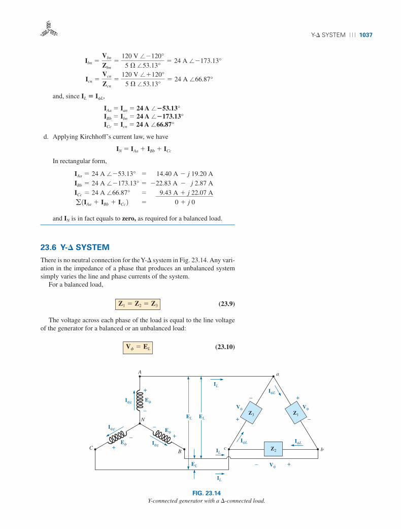
23.6 Y-� SYSTEM
There is no neutral connection for the Y-� system in Fig. 23.14. Any vari-ation in the impedance of a phase that produces an unbalanced systemsimply varies the line and phase currents of the system.
For a balanced load,
(23.9)
The voltage across each phase of the load is equal to the line voltageof the generator for a balanced or an unbalanced load:
(23.10)Vf � EL
Z1 � Z2 � Z3
IAa � 24 A ��53.13°
IBb � 24 A ��173.13°
ICc � 24 A �66.87°
g 1IAa � IBb � ICc 2
� 14.40 A � j 19.20 A
� �22.83 A � �j 2.87 A
� �9.43 A � j 22.07 A
� 0 � j 0 ���
Icn �Vcn
Zcn
�120 V ��120°
5 � �53.13°� 24 A �66.87°
Ibn �Vbn
Zbn
�120 V ��120°
5 � �53.13°� 24 A ��173.13°
IL
IL
EL
Ifg
+
–
A
NIfg
+
–
CB
Ifg
+
–
Ef
Ef
EL
ILc
EL
IfL
a
IfL
Ef
Vf+–
b
Vf
+
–
Z2
IfL
Z3 Z1
Vf
–
+
FIG. 23.14
Y-connected generator with a �-connected load.
boy30444_ch23.qxd 3/24/06 3:37 PM Page 1037

1038 ⏐⏐⏐ POLYPHASE SYSTEMS
The relationship between the line currents and phase currents of a bal-anced � load can be found using an approach very similar to that used inSection 23.3 to find the relationship between the line voltages and phasevoltages of a Y-connected generator. For this case, however, Kirchhoff’scurrent law is used instead of Kirchhoff’s voltage law.
The results obtained are
(23.11)
and the phase angle between a line current and the nearest phase currentis 30°. A more detailed discussion of this relationship between the lineand phase currents of a �-connected system can be found in Section 23.7.
For a balanced load, the line currents will be equal in magnitude, aswill the phase currents.
EXAMPLE 23.2 For the three-phase system in Fig. 23.15:
a. Find the phase angles u2 and u3.b. Find the current in each phase of the load.c. Find the magnitude of the line currents.
IL � 13If
ECA = 150 V ∠ v3
IAa
ICc
A
C
B
IBbc
a
+–
b
+
Ica3-phase, 3-wire,Y-connected generatorPhase sequence: ABC
EAB = 150 V ∠ 0°
XL = 8 �
Vbc
–
– +
R = 6 �
Iab
Ibc XL = 8 �
R = 6 �
R = 6 �
Vca Vab
XL = 8 �
EBC = 150 V ∠ v2
FIG. 23.15
Example 23.2.
Solutions:
a. For an ABC sequence,
u2 � �120° and u3 � �120°
b. Vf � EL. Therefore,
Vab � EAB Vca � ECA Vbc � EBC
The phase currents are
Ica �Vca
Zca
�150 V ��120°
10 � �53.13°� 15 A �66.87°
Ibc �Vbc
Zbc
�150 V ��120°
10 � �53.13°� 15 A ��173.13°
Iab �Vab
Zab
�150 V �0°
6 � � j 8 ��
150 V �0°
10 � �53.13°� 15 A ��53.13°
boy30444_ch23.qxd 3/24/06 3:38 PM Page 1038

�-CONNECTED GENERATOR ⏐⏐⏐ 1039
eAN
A
+
–N
NN
+ +
––eCN eBN
BC
(a)
ECA
A
+
–
+
+
–
C
(b)
IAC
EAB
ECN EAN
–
B– +EBC ICB ICc
IBb
Load
EBN
–
+
–
IBA IAa
+
FIG. 23.16
�-connected generator.
c. Therefore,
IAa � IBb � ICc � 25.95 A
23.7 �-CONNECTED GENERATOR
If we rearrange the coils of the generator in Fig. 23.16(a) as shown inFig. 23.16(b), the system is referred to as a three-phase, three-wire,�-connected ac generator. In this system, the phase and line voltagesare equivalent and equal to the voltage induced across each coil of thegenerator; that is,
or (23.12)EL � Efg
EAB � EAN� and�eAN � 12EAN sin vt
EBC � EBN �and�eBN � 12EBN sin1vt � 120° 2ECA � ECN �and�eCN � 12ECN sin1vt � 120° 2
¶Phase
sequence
ABC
IL � 13If � 11.73 2 115 A 2 � 25.95 A.
Note that only one voltage (magnitude) is available instead of the twoavailable in the Y-connected system.
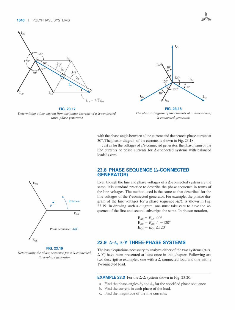
Unlike the line current for the Y-connected generator, the line currentfor the �-connected system is not equal to the phase current. The rela-tionship between the two can be found by applying Kirchhoff’s currentlaw at one of the nodes and solving for the line current in terms of thephase currents; that is, at node A,
IBA � IAa � IAC
or IAa � IBA � IAC � IBA � ICA
The phasor diagram is shown in Fig. 23.17 for a balanced load.Using the same procedure to find the line current as was used to find
the line voltage of a Y-connected generator produces the following:
In general:
(23.13)IL � 13Ifg
IAa � 13IBA ��30°
IBb � 13ICB ��150°
ICc � 13IAC �90°
boy30444_ch23.qxd 3/24/06 3:38 PM Page 1039
1040 ⏐⏐⏐ POLYPHASE SYSTEMS
120°
120°
IAa
ICB
IBA
IAC
60°
ICA
30°
30°
IAa = �3 IBA
IBA
�32
IBA
�32
FIG. 23.17
Determining a line current from the phase currents of a �-connected,three-phase generator.
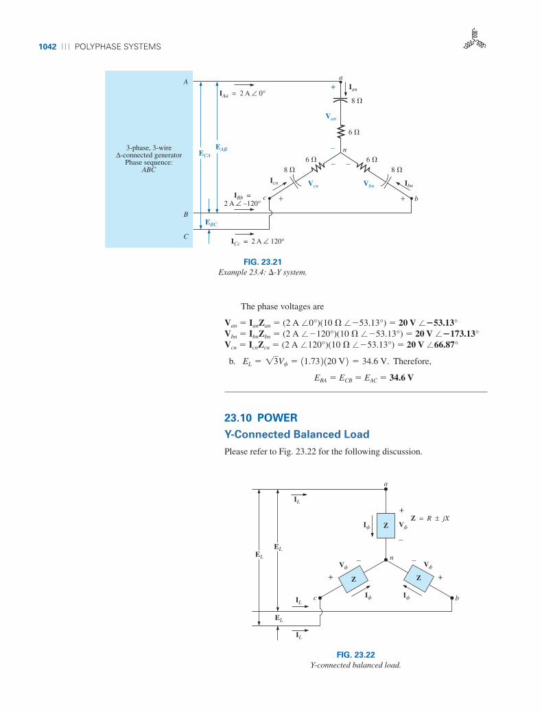
with the phase angle between a line current and the nearest phase current at30°. The phasor diagram of the currents is shown in Fig. 23.18.
Just as for the voltages of aY-connected generator, the phasor sum of theline currents or phase currents for �-connected systems with balancedloads is zero.
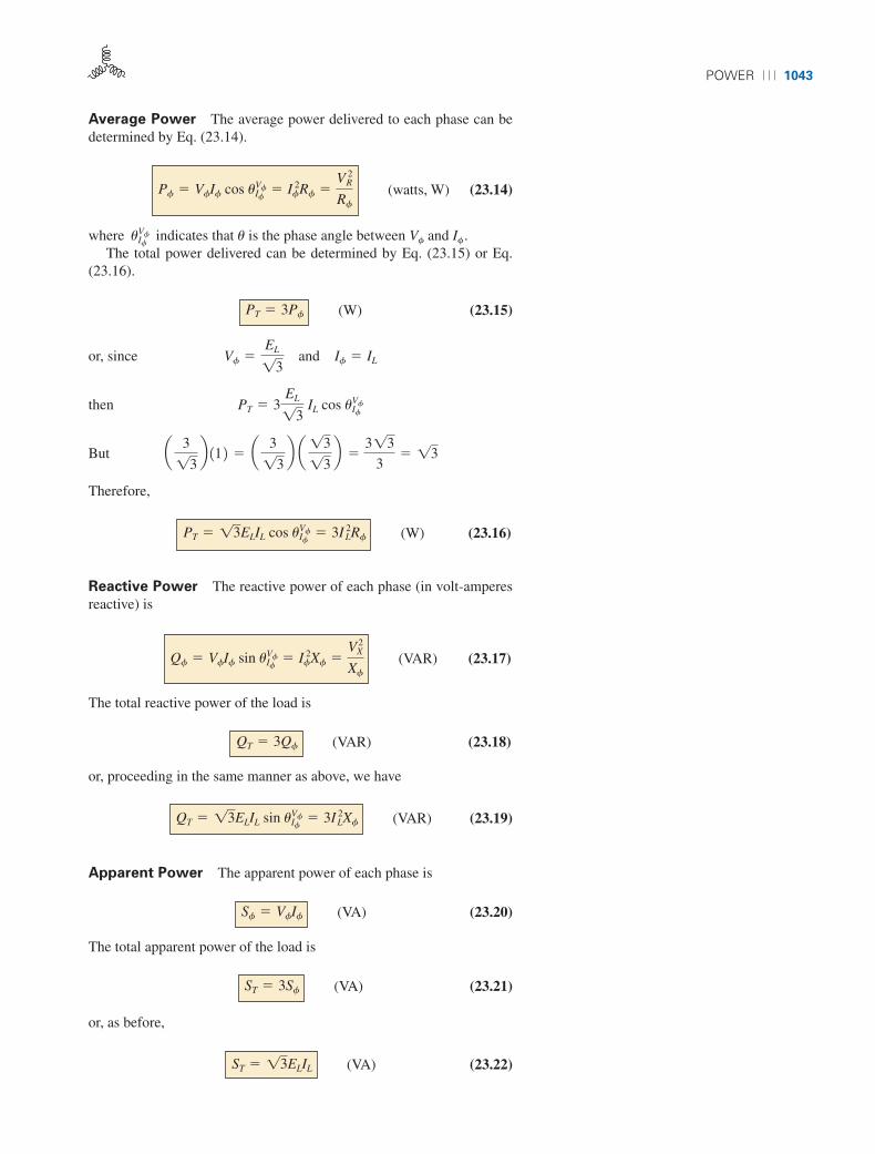
23.8 PHASE SEQUENCE (�-CONNECTEDGENERATOR)
Even though the line and phase voltages of a �-connected system are thesame, it is standard practice to describe the phase sequence in terms ofthe line voltages. The method used is the same as that described for theline voltages of the Y-connected generator. For example, the phasor dia-gram of the line voltages for a phase sequence ABC is shown in Fig.23.19. In drawing such a diagram, one must take care to have the se-quence of the first and second subscripts the same. In phasor notation,
EAB � EAB �0°EBC � EBC � �120°ECA � ECA �120°
23.9 �-�, �-Y THREE-PHASE SYSTEMS
The basic equations necessary to analyze either of the two systems (�-�,�-Y) have been presented at least once in this chapter. Following aretwo descriptive examples, one with a �-connected load and one with aY-connected load.
EXAMPLE 23.3 For the �-� system shown in Fig. 23.20:
a. Find the phase angles u2 and u3 for the specified phase sequence.b. Find the current in each phase of the load.c. Find the magnitude of the line currents.
120°
120°120°
ICB
IBA
IAC
30°
30°IBb
ICc
30°
IAa
FIG. 23.18
The phasor diagram of the currents of a three-phase,�-connected generator.
P
EAB
ECA
EBC
Rotation
Phase sequence: ABC
FIG. 23.19
Determining the phase sequence for a �-connected,three-phase generator.
boy30444_ch23.qxd 3/24/06 3:38 PM Page 1040

�-�, �-Y THREE-PHASE SYSTEMS ⏐⏐⏐ 1041
IAa
ICc
A
C
B
EBC = 120 V ∠ v2
IBb
c
a
+–
b
+
Ica
3-phase, 3-wireΔ-connected ac generator
Phase sequence: ACB
ECA = 120 V ∠ v3
EAB = 120 V ∠ 0°
Vbc
–
– +Iab
Ibc
5 �
Vca
Vab
5 �
5 � 5 �
5 �5 �
FIG. 23.20
Example 23.3: �-� system.
Solutions:
a. For an ACB phase sequence,
u2 � 120° and u3 � �120°
b. Vf � EL. Therefore,
Vab � EAB Vca � ECA Vbc � EBC
The phase currents are
c. Therefore,
IAa � IBb � ICc � 58.82 A
EXAMPLE 23.4 For the �-Y system shown in Fig. 23.21:
a. Find the voltage across each phase of the load.b. Find the magnitude of the line voltages.
Solutions:
a. IfL � IL. Therefore,
Ian � IAa � 2 A �0°Ibn � IBb � 2 A � �120°Icn � ICc � 2 A �120°
IL � 13If � 11.73 2 134 A 2 � 58.82 A.
Ica �Vca
Zca
�120 V ��120°
3.54 � ��45°� 33.9 A ��75°
Ibc �Vbc
Zbc
�120 V �120°
3.54 � ��45°� 33.9 A �165°
�120 V �0°
3.54 � ��45°� 33.9 A �45°
Iab �Vab
Zab
�120 V �0°
15 � �0° 2 15 � ��90° 25 � � j 5 �
�120 V �0°
25 � ��90°
7.071 ��45°
boy30444_ch23.qxd 3/24/06 3:38 PM Page 1041
1042 ⏐⏐⏐ POLYPHASE SYSTEMS
A
C
B
ICc = 2 A ∠ 120°
c
a
+ b
Icn
ECA
EAB
Vbn
6 �
8 �
3-phase, 3-wireΔ-connected generator
Phase sequence:ABC
IAa = 2 A ∠ 0°
EBC
IBb =2 A ∠ –120°
+
+
–
IbnVcn
Ian
Van
n
– –6 �8 �
6 �8 �
FIG. 23.21
Example 23.4: �-Y system.
The phase voltages are
Van � IanZan � (2 A �0°)(10 � ��53.13°) � 20 V ��53.13°Vbn � IbnZbn � (2 A ��120°)(10 � ��53.13°) � 20 V ��173.13°Vcn � IcnZcn � (2 A �120°)(10 � ��53.13°) � 20 V �66.87°
b. Therefore,
EBA � ECB � EAC � 34.6 V
23.10 POWER
Y-Connected Balanced Load
Please refer to Fig. 23.22 for the following discussion.
EL � 13Vf � 11.73 2 120 V 2 � 34.6 V.
IL
IL
EL
IL
+
–
+
–
I��
V��
I��
V��
a
bc
I�� V��
Z = R ± jX
+
– n
ELEL
Z
Z Z
FIG. 23.22
Y-connected balanced load.
boy30444_ch23.qxd 3/24/06 3:38 PM Page 1042
POWER ⏐⏐⏐ 1043
Average Power The average power delivered to each phase can bedetermined by Eq. (23.14).
(watts, W) (23.14)
where indicates that u is the phase angle between Vf and If .The total power delivered can be determined by Eq. (23.15) or Eq.
(23.16).
(W) (23.15)
or, since
then
But
Therefore,
(W) (23.16)
Reactive Power The reactive power of each phase (in volt-amperesreactive) is
(VAR) (23.17)
The total reactive power of the load is
(VAR) (23.18)
or, proceeding in the same manner as above, we have
(VAR) (23.19)
Apparent Power The apparent power of each phase is
(VA) (23.20)
The total apparent power of the load is
(VA) (23.21)
or, as before,
(VA) (23.22)ST � 13ELIL
ST � 3Sf
Sf � VfIf
QT � 13ELIL sin uIfVf � 3IL
2Xf
QT � 3Qf
Qf � VfIf sin uIfVf � If
2Xf �VX
2
Xf
PT � 13ELIL cos uIfVf � 3IL
2Rf
a 3
13b 11 2 � a 3
13b a 13
13b �
313
3� 13
PT � 3EL
13 IL cos uIf
Vf
Vf �EL
13 and If � IL
PT � 3Pf
uIfVf
Pf � VfIf cos uIfVf � If
2Rf �VR
2
Rf
boy30444_ch23.qxd 3/24/06 3:38 PM Page 1043

1044 ⏐⏐⏐ POLYPHASE SYSTEMS
a
+
–n
c
XL = 4 �
R = 3 �
XL = 4 �
+
R = 3 � R = 3 �
XL = 4 �
+
–
EL = 173.2 V – 120°
EL = 173.2 V + 120°EL = 173.2 V 0°
b
–
I�� V��
I��
V�� V��
I��
FIG. 23.23
Example 23.5.
Power Factor The power factor of the system is given by
(23.23)
EXAMPLE 23.5 For the Y-connected load in Fig. 23.23:
Fp �PT
ST
� cos uIfVf���1leading or lagging 2
a. Find the average power to each phase and the total load.b. Determine the reactive power to each phase and the total reactive
power.c. Find the apparent power to each phase and the total apparent power.d. Find the power factor of the load.
Solutions:
a. The average power is
or
b. The reactive power is
or
or
QT � 13ELIL sin uIfVf � 11.732 2 1173.2 V 2 120 A 2 10.8 2 � 4800 VAR
QT � 3Qf � 13 2 11600 VAR 2 � 4800 VAR Qf � I 2
fXf � 120 A 2 214 � 2 � 1400 2 14 2 � 1600 VAR
� 1600 VAR Qf � VfIf sin uIf
Vf � 1100 V 2 120 A 2 sin 53.13° � 12000 2 10.8 2
PT � 13ELIL cos uIfVf � 11.732 2 1173.2 V 2 120 A 2 10.6 2 � 3600 W
PT � 3Pf � 13 2 11200 W 2 � 3600 W
Pf �VR
2
Rf�160 V 2 2
3 ��
3600
3� 1200 W
Pf � If2Rf � 120 A 2 213 � 2 � 1400 2 13 2 � 1200 W
� 1200 W Pf � VfIf cos uIf
Vf � 1100 V 2 120 A 2 cos 53.13° � 12000 2 10.6 2
boy30444_ch23.qxd 3/24/06 3:39 PM Page 1044

POWER ⏐⏐⏐ 1045
c. The apparent power is
Sf � VfIf � (100 V)(20 A) � 2000 VA
ST � 3Sf � (3)(2000 VA) � 6000 VA
or
d. The power factor is
�-Connected Balanced Load
Please refer to Fig. 23.24 for the following discussion.
Fp �PT
ST
�3600 W
6000 VA� 0.6 lagging
ST � 13ELIL � 11.732 2 1173.2 V 2 120 A 2 � 6000 VA
IL
EL
Z Z
Z
+
–
I��
+
–V��
I��
EL
IL
EL
IL
V��– +
Z = R ± jX� �
I��
V��
FIG. 23.24
�-connected balanced load.
Average Power
(W) (23.24)
(W) (23.25)
Reactive Power
(VAR) (23.26)
(VAR) (23.27)
Apparent Power
(VA) (23.28)Sf � VfIf
QT � 3Qf
Qf � VfIf sin uIfVf � If
2Xf �VX
2
Xf
PT � 3Pf
Pf � VfIf cos uIfVf � If
2Rf �VR
2
Rf
boy30444_ch23.qxd 3/24/06 3:39 PM Page 1045

1046 ⏐⏐⏐ POLYPHASE SYSTEMS
EL = 200 V ∠ 0°
6 �
EL = 200 V ∠ –120°
EL = 200 V ∠ +120°
8 �
4 � 4 �
4 �6 �
8 � 6 �
8 �
3 �
3 �3 �
FIG. 23.25
Example 23.6.
(VA) (23.29)
Power Factor
(23.30)
EXAMPLE 23.6 For the �-Y connected load in Fig. 23.25, find the to-tal average, reactive, and apparent power. In addition, find the power fac-tor of the load.
Fp �PT
ST
ST � 3Sf � 13ELIL
Solution: Consider the � and Y separately.
For the �:
For the Y:
STY� 3VfIf � 13 2 1116 V 2 123.12 A 2 � 8045.76 VA
QTY� 3If
2Xf � 13 2 123.12 A 2 213 � 2 � 4810.81 VAR 1L 2 PTY
� 3If2Rf � 13 2 123.12 A 2 214 � 2 � 6414.41 W
If �EL>13
ZY�
200 V>13
5 ��
116 V
5 �� 23.12 A
ZY � 4 � � j 3 � � 5 � �36.87°
ST¢
� 3VfIf � 13 2 1200 V 2 120 A 2 � 12,000 VA
QT¢
� 3If2Xf � 13 2 120 A 2 218 � 2 � 9600 VAR 1C 2
PT¢
� 3If2Rf � 13 2 120 A 2 216 � 2 � 7200 W
If �EL
Z¢
�200 V
10 �� 20 A
Z¢
� 6 � � j 8 � � 10 � ��53.13°
boy30444_ch23.qxd 3/24/06 3:39 PM Page 1046

POWER ⏐⏐⏐ 1047
For the total load:
EXAMPLE 23.7 Each transmission line of the three-wire, three-phasesystem in Fig. 23.26 has an impedance of 15 � � j 20 �. The system de-livers a total power of 160 kW at 12,000 V to a balanced three-phase loadwith a lagging power factor of 0.86.
Fp �PT
ST
�13,614.41 W
14,432.20 VA� 0.943 leading
� 14,432.2 VA
ST � 2PT2 � QT
2 � 2113,614.41 W 2 2 � 14789.19 VAR 2 2 � 4789.19 VAR 1C 2
QT � QT¢
� QTY� 9600 VAR 1C 2 � 4810.81 VAR 1I 2
PT � PT¢
� PTY� 7200 W � 6414.41 W � 13,614.41 W
A
N
C B
15 � 20 �
15 � 20 �
15 � 20 �
Z1 = Z2 = Z3
a
n12 k VEAB
c
Z2
Z1
Z3
b
FIG. 23.26
Example 23.7.
a. Determine the magnitude of the line voltage EAB of the generator.b. Find the power factor of the total load applied to the generator.c. What is the efficiency of the system?
Solutions:
a.
and
Since u� cos�1 0.86 � 30.68°, assigning Vf an angle of 0° or Vf �Vf �0°, a lagging power factor results in
If � 8.94 A ��30.68°
For each phase, the system will appear as shown in Fig. 23.27, where
EAN � IfZline � Vf � 0
� 8.94 A
If �PT
3Vf cos u�
160,000 W
316936.42 V 2 10.86 2
PT 1load 2 � 3VfIf cos u
Vf 1load 2 �VL
13�
12,000 V
1.73� 6936.42 V
boy30444_ch23.qxd 3/24/06 3:39 PM Page 1047

1048 ⏐⏐⏐ POLYPHASE SYSTEMS
If = 8.94 A ∠ –30.68°A
15 � IfIL 20 �
EAN
+
–
+
–
VfZ1
Zline
FIG. 23.27
The loading on each phase of the system in Fig. 23.26.
orEAN � IfZline � Vf
� (8.94 A ��30.68°)(25 � �53.13°) � 6936.42 V �0°� 223.5 V �22.45° � 6936.42 V �0°� 206.56 V � j 85.35 V � 6936.42 V� 7142.98 V � j 85.35 V� 7143.5 V �0.68°
Then
b. PT � Pload � Plines
� 160 kW � 3(IL )2 Rline
� 160 kW � 3(8.94 A)215 �� 160,000 W � 3596.55 W� 163,596.55 W
and
or
and Fp � 0.856 < 0.86 of load
c.
23.11 THREE-WATTMETER METHOD
The power delivered to a balanced or an unbalanced four-wire,Y-connected load can be found by the three-wattmeter method, that is,by using three wattmeters in the manner shown in Fig. 23.28. Eachwattmeter measures the power delivered to each phase. The potential coilof each wattmeter is connected parallel with the load, while the currentcoil is in series with the load. The total average power of the system canbe found by summing the three wattmeter readings; that is,
(23.31)
For the load (balanced or unbalanced), the wattmeters are connected asshown in Fig. 23.29. The total power is again the sum of the threewattmeter readings:
(23.32)PT¢
� P1 � P2 � P3
PTY� P1 � P2 � P3
� 97.8%
h �Po
Pi
�Po
Po � Plosses�
160 kW
160 kW � 3596.55 W� 0.978
cos uT �PT
13VLIL
�163,596.55 W
11.73 2 112,358.26 V 2 18.94 A 2
PT � 13VLIL cos uT
� 12,358.26 V EAB � 13Efg � 11.73 2 17143.5 V 2
boy30444_ch23.qxd 3/24/06 3:40 PM Page 1048

TWO-WATTMETER METHOD ⏐⏐⏐ 1049
+–
Z1
Line
Neutral
P3
P1
P2
+–CC1
PC1
CC2
PC2
CC3
PC3
+–
+–
+–
+–
Line
a
bc
n
Line
Z3 Z2
FIG. 23.28
Three-wattmeter method for a Y-connected load.
If in either of the cases just described the load is balanced, the powerdelivered to each phase will be the same. The total power is then just threetimes any one wattmeter reading.
23.12 TWO-WATTMETER METHOD
The power delivered to a three-phase, three-wire, �- or Y-connected, bal-anced or unbalanced local can be found using only two wattmeters if theproper connection is employed and if the wattmeter readings are inter-preted properly. The basic connections of this two-wattmeter methodare shown in Fig. 23.30. One end of each potential coil is connected tothe same line. The current coils are then placed in the remaining lines.
The connection shown in Fig. 23.31 also satisfies the requirements. Athird hookup is also possible, but this is left to the reader as an exercise.
The total power delivered to the load is the algebraic sum of the twowattmeter readings. For a balanced load, we now consider two methodsof determining whether the total power is the sum or the difference of thetwo wattmeter readings. The first method to be described requires that weknow or are able to find the power factor (leading or lagging) of any one
+–
P1
P2
+–
CC1
PC1
CC2
PC2
CC3
P3+–
+–+–
Line
a
bc
Line
Line
Z2
PC3
+– Z3 Z1
FIG. 23.29
Three-wattmeter method for a �-connected load.
Line
a
�- or Y-connected
load
Line
Line
c
b
+–
+–+–
+–P1 CC1
PC1
P2CC2
PC2
FIG. 23.30
Two-wattmeter method for a �- or a Y-connected load.
Line
a
�- or Y-connected
load
Line
Line
c
b
+–
+–+–
+–P1CC1
PC1
P2CC2
PC2
FIG. 23.31
Alternative hookup for the two-wattmeter method.
boy30444_ch23.qxd 3/24/06 3:40 PM Page 1049

1050 ⏐⏐⏐ POLYPHASE SYSTEMS
phase of the load. When this information has been obtained, it can be ap-plied directly to the curve in Fig. 23.32.
The curve in Fig. 23.32 is a plot of the power factor of the load (phase)versus the ratio Pl /Ph, where Pl and Ph are the magnitudes of the lower-and higher-reading wattmeters, respectively. Note that for a power factor(leading or lagging) greater than 0.5, the ratio has a positive value. Thisindicates that both wattmeters are reading positive, and the total power isthe sum of the two wattmeter readings; that is, PT � Pl � Ph. For a powerfactor less than 0.5 (leading or lagging), the ratio has a negative value.This indicates that the smaller-reading wattmeter is reading negative,and the total power is the difference of the two wattmeter readings; thatis, PT � Ph � Pl.
A closer examination reveals that, when the power factor is 1(cos 0° � 1), corresponding to a purely resistive load, Pl /Ph � 1 or Pl �Ph, and both wattmeters have the same wattage indication. At a powerfactor equal to 0 (cos 90° � 0), corresponding to a purely reactive load,Pl /Ph � �1 or Pl � �Ph, and both wattmeters again have the samewattage indication but with opposite signs. The transition from a negativeto a positive ratio occurs when the power factor of the load is 0.5 oru� cos�1 0.5 � 60°. At this power factor, Pl /Ph � 0, so that Pl � 0, whilePh reads the total power delivered to the load.
The second method for determining whether the total power is the sumor difference of the two wattmeter readings involves a simple laboratorytest. For the test to be applied, both wattmeters must first have an up-scaledeflection. If one of the wattmeters has a below-zero indication, an up-scale deflection can be obtained by simply reversing the leads of the cur-rent coil of the wattmeter. To perform the test:
1. Take notice of which line does not have a current coil sensing theline current.
2. For the lower-reading wattmeter, disconnect the lead of the po-tential coil connected to the line without the current coil.
3. Take the disconnected lead of the lower-reading wattmeter’s po-tential coil, and touch a connection point on the line that has thecurrent coil of the higher-reading wattmeter.
4. If the pointer deflects downward (below zero watts), the wattagereading of the lower-reading wattmeter should be subtracted fromthat of the higher-reading wattmeter. Otherwise, the readingsshould be added.
0.2
0–0.25–0.5–0.75–1.0 +0.25 +0.5 +0.75 +1.0
Pow
er f
acto
rL
ead
or la
g
0.4
0.6
0.8
1.0
0.5
Fp
PT = Ph – Pl PT = Pl + Ph
Pl Ph/
FIG. 23.32
Determining whether the readings obtained using the two-wattmeter methodshould be added or subtracted.
boy30444_ch23.qxd 3/24/06 3:40 PM Page 1050
TWO-WATTMETER METHOD ⏐⏐⏐ 1051
For a balanced system, since
the power factor of the load (phase) can be found from the wattmeterreadings and the magnitude of the line voltage and current:
(23.33)
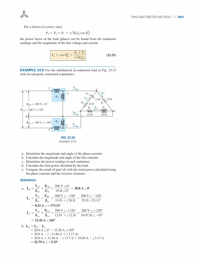
EXAMPLE 23.8 For the unbalanced �-connected load in Fig. 23.33with two properly connected wattmeters:
Fp � cos uIfVf �
Ph Pl
13ELIL
PT � Ph P1 � 13ELIL cos uIfVf
15 �
EBC = 208 V ∠ –120°
EAB = 208 V ∠ 0°
20 �
aA
10 �
12 �
R2
R1
XL
12 �
bc
XCIab
Ica
R3
Ibc
IBb
IAa
ICc
+–+–
ECA = 208 V ∠ 120°
+–+–
B
C
W1
W2
FIG. 23.33
Example 23.8.
a. Determine the magnitude and angle of the phase currents.b. Calculate the magnitude and angle of the line currents.c. Determine the power reading of each wattmeter.d. Calculate the total power absorbed by the load.e. Compare the result of part (d) with the total power calculated using
the phase currents and the resistive elements.
Solutions:
a.
b. IAa � Iab � Ica
� 20.8 A �0° � 12.26 A �165°� 20.8 A � (�11.84 A � j 3.17 A)� 20.8 A � 11.84 A � j 3.17 A � 32.64 A � j 3.17 A� 32.79 A ��5.55°
� 12.26 A �165°
Ica �Vca
Zca
�ECA
Zca
�208 V ��120°
12 � � j 12 ��
208 V ��120°
16.97 � ��45°
� 8.32 A ��173.13°
Ibc �Vbc
Zbc
�EBC
Zbc
�208 V ��120°
15 � � j 20 ��
208 V ��120°
25 � �53.13°
Iab �Vab
Zab
�EAB
Zab
�208 V �0°
10 � �0°� 20.8 A �0°
boy30444_ch23.qxd 3/24/06 3:40 PM Page 1051

1052 ⏐⏐⏐ POLYPHASE SYSTEMS
IBb � Ibc � Iab
� 8.32 A ��173.13° � 20.8 A �0°� (�8.26 A � j 1 A) � 20.8 A� �8.26 A � 20.8 A � j 1 A � �29.06 A � j 1 A� 29.08 A ��178.03°
ICc � Ica � Ibc
� 12.26 A �165° � 8.32 A � �173.13°� (�11.84 A � j 3.17 A) � (�8.26 A � j 1 A)� �11.84 A � 8.26 A � j (3.17 A � 1 A) � �3.58 A � j 4.17 A� 5.5 A �130.65°
c.
but Vcb � ECB � 208 V ��120° � 180°� 208 V �60°
with ICc � 5.5 A �130.65°
d. PT � P1 � P2 � 6788.35 W � 379.1 W� 7167.45 W
e. PT � (Iab)2R1 � (Ibc)
2R2 � (Ica)2R3
� (20.8 A)210 � � (8.32 A)215 � � (12.26 A)212 �� 4326.4 W � 1038.34 W � 1803.69 W� 7168.43 W
(The slight difference is due to the level of accuracy carried throughthe calculations.)
23.13 UNBALANCED, THREE-PHASE, FOUR-WIRE,Y-CONNECTED LOAD
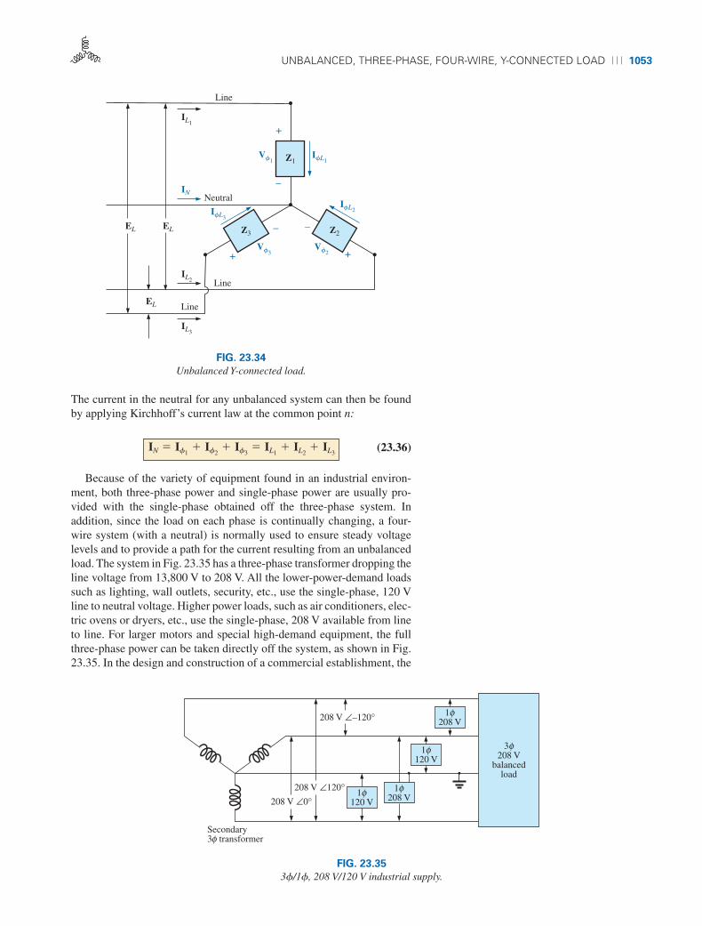
For the three-phase, four-wire,Y-connected load in Fig. 23.34, conditionsare such that none of the load impedances are equal—hence we have anunbalanced polyphase load. Since the neutral is a common point be-tween the load and source, no matter what the impedance of each phaseof the load and source, the voltage across each phase is the phase voltageof the generator:
(23.34)
The phase currents can therefore be determined by Ohm’s law:
(23.35)If1�
Vf1
Z1�
Ef1
Z1 and so on
Vf � Ef
� 379.1 W � 1208 V 2 15.5 A 2 cos 70.65°
P2 � VcbICc cos uICc
Vcb
Vbc � EBC � 208 V ��120°
� 6788.35 W � 1208 V 2 132.79 A 2 cos 5.55°
IAa � 32.79 A ��5.55° P1 � VabIAa cos uIAa
Vab Vab � 208 V �0°
boy30444_ch23.qxd 3/24/06 3:40 PM Page 1052
UNBALANCED, THREE-PHASE, FOUR-WIRE, Y-CONNECTED LOAD ⏐⏐⏐ 1053
The current in the neutral for any unbalanced system can then be foundby applying Kirchhoff’s current law at the common point n:
(23.36)
Because of the variety of equipment found in an industrial environ-ment, both three-phase power and single-phase power are usually pro-vided with the single-phase obtained off the three-phase system. Inaddition, since the load on each phase is continually changing, a four-wire system (with a neutral) is normally used to ensure steady voltagelevels and to provide a path for the current resulting from an unbalancedload. The system in Fig. 23.35 has a three-phase transformer dropping theline voltage from 13,800 V to 208 V. All the lower-power-demand loadssuch as lighting, wall outlets, security, etc., use the single-phase, 120 Vline to neutral voltage. Higher power loads, such as air conditioners, elec-tric ovens or dryers, etc., use the single-phase, 208 V available from lineto line. For larger motors and special high-demand equipment, the fullthree-phase power can be taken directly off the system, as shown in Fig.23.35. In the design and construction of a commercial establishment, the
IN � If1� If2
� If3� IL1
� IL2� IL3
Line
IL1
Line
Line
Neutral
IfL1
+
–
+
–
+
–
IN
IL2
Vf1 Z1
IL3
IfL2
Vf2
Z2Z3
Vf3
IfL3
EL
EL EL
FIG. 23.34
Unbalanced Y-connected load.
208 V ∠–120°
208 V ∠120°208 V ∠0°
Secondary3 transformerφ
1 φ120 V
1 φ208 V
1 φ120 V
1 φ208 V
208 Vbalanced
load
φ3
FIG. 23.35
3f/1f, 208 V/120 V industrial supply.
boy30444_ch23.qxd 3/24/06 3:40 PM Page 1053

1054 ⏐⏐⏐ POLYPHASE SYSTEMS
National Electric Code requires that every effort be made to ensure thatthe expected loads, whether they be single- or multiphase, result in a to-tal load that is as balanced as possible between the phases, thus ensuringthe highest level of transmission efficiency.
23.14 UNBALANCED, THREE-PHASE, THREE-WIRE, Y-CONNECTED LOAD
For the system shown in Fig. 23.36, the required equations can be de-rived by first applying Kirchhoff’s voltage law around each closed loopto produce
EAB � Van � Vbn � 0EBC � Vbn � Vcn � 0ECA � Vcn � Van � 0
Z1
Z2Z3
ECA
EBC
EABECA
+
–
Vcn
+
–
Van
+
–
Ian
EAB+
–
Ibn
Icn
–
+Vbn
EBC+–
n
a
c b
FIG. 23.36
Unbalanced, three-phase, three-wire, Y-connected load.
Substituting, we have
Van � IanZ1 Vbn � IbnZ2 Vcn � IcnZ3
Applying Kirchhoff’s current law at node n results in
Ian � Ibn � Icn � 0 and Ibn � �Ian � Icn
Substituting for Ibn in Eqs. (23.37a) and (23.37b) yields
EAB � IanZ1 � [�(Ian � Icn)]Z2
EBC � �(Ian � Icn)Z2 � IcnZ3
which are rewritten as
EAB � Ian(Z1 � Z2) � IcnZ2
EBC � Ian(�Z2) � Icn[�(Z2 � Z3)]
Using determinants, we have
123.37a 2123.37b 2123.37c 2
EAB � IanZ1 � IbnZ2
EBC � IbnZ2 � IcnZ3
ECA � IcnZ3 � IanZ1
boy30444_ch23.qxd 3/24/06 3:40 PM Page 1054

UNBALANCED, THREE-PHASE,THREE-WIRE, Y-CONNECTED LOAD ⏐⏐⏐ 1055
Applying Kirchhoff’s voltage law to the line voltages:
EAB � ECA � EBC � 0 or EAB � EBC � �ECA
Substituting for (EAB � ECB) in the above equation for Ian:
and (23.38)
In the same manner, it can be shown that
(23.39)
Substituting Eq. (23.39) for Icn in the right-hand side of Eq. (23.37b), weobtain
(23.40)
EXAMPLE 23.9 A phase-sequence indicator is an instrument that candisplay the phase sequence of a polyphase circuit. A network that per-forms this function appears in Fig. 23.37. The applied phase sequence isABC. The bulb corresponding to this phase sequence burns more brightlythan the bulb indicating the ACB sequence because a greater current ispassing through the ABC bulb. Calculating the phase currents demon-strates that this situation does in fact exist:
By Eq. (23.39),
Z1 � XC �1
vC�
1
1377 rad>s 2 116 10�6 F 2 � 166 �
Ibn �EBCZ1 � EABZ3
Z1Z2 � Z1Z3 � Z2Z3
Icn �ECAZ2 � EBCZ1
Z1Z2 � Z1Z3 � Z2Z3
Ian �EABZ3 � ECAZ2
Z1Z2 � Z1Z3 � Z2Z3
Ian ��Z21�ECA 2 � Z3EAB
�Z1Z2 � Z1Z3 � Z2Z3
Ian ��Z21EAB � EBC 2 � Z3EAB
�Z1Z2 � Z1Z3 � Z2Z3
��1Z2 � Z3 2EAB � EBCZ2
�Z1Z2 � Z1Z3 � Z2Z3 � Z22 � Z2
2
Ian �
`EAB Z2
EBC �1Z2 � Z3 2 `` Z1 � Z2 Z2
�Z2 �1Z2 � Z3 2 `
�1200 V �120° 2 1200 � �0° 2 � 1200 V ��120° 2 1166 � ��90° 2
1166 � ��90° 2 1200 � �0° 2 � 1166 � ��90° 2 1200 � �0° 2 � 1200 � �0° 2 1200 � �0° 2
Icn �ECAZ2 � EBCZ1
Z1Z2 � Z1Z3 � Z2Z3
boy30444_ch23.qxd 3/24/06 3:41 PM Page 1055

1056 ⏐⏐⏐ POLYPHASE SYSTEMS
Dividing the numerator and denominator by 1000 and converting both tothe rectangular domain yields
By Eq. (23.40),
Dividing by 1000 and converting to the rectangular domain yields
and Ibn > Icn by a factor of more than 3 : 1. Therefore, the bulb indicatingan ABC sequence will burn more brightly due to the greater current. If thephase sequence were ACB, the reverse would be true.
�70.73 �166.43°
77.52 ��58.93°� 0.91 A �225.36°
Ibn ��28.75 � j 16.60 � 40.0
77.52 ��58.93°�
�68.75 � j 16.60
77.52 ��58.93°
Ibn �33,200 V ��210° � 40,000 V �0°
77.52 103 � ��58.93°
�1200 V ��120° 2 1166 ��90° 2 � 1200 V �0° 2 1200 �0° 2
77.52 103 � ��58.93°
Ibn �EBCZ1 � EABZ3
Z1Z2 � Z1Z3 � Z2Z3
Icn � 0.259 A �123.06°
�8.75 � j 18.04
77.52 ��58.93°�
20.05 �64.13°
77.52 ��58.93°
Icn �1�20 � j 34.64 2 � 128.75 � j 16.60 2
40 � j 66.4
Icn �40,000 V �120° � 33,200 V ��30°
33,200 � ��90° � 33,200 � ��90° � 40,000 � �0°
EAB = 200 V ∠ 0°
200 �
EBC = 200 V ∠ –120°
ECA = 200 V ∠ +120°
f = 60 Hz
16 mF
ACB
a (1)
(3) c b (2)
Z1Bulbs (150 W)200 � internal
resistance
200 �
ABC
nZ3 Z2
FIG. 23.37
Example 23.9.
boy30444_ch23.qxd 3/24/06 3:41 PM Page 1056
PROBLEMS ⏐⏐⏐ 1057
PROBLEMS
SECTION 23.5 Y-Connected Generator with a
Y-Connected Load
1. A balanced Y load having a 10 � resistance in each leg isconnected to a three-phase, four-wire,Y-connected generatorhaving a line voltage of 208 V. Calculate the magnitude ofa. the phase voltage of the generator.b. the phase voltage of the load.c. the phase current of the load.d. the line current.
2. Repeat Problem 1 if each phase impedance is changed to a12 � resistor in series with a 16 � capacitive reactance.
3. Repeat Problem 1 if each phase impedance is changed to a10 � resistor in parallel with a 10 � capacitive reactance.
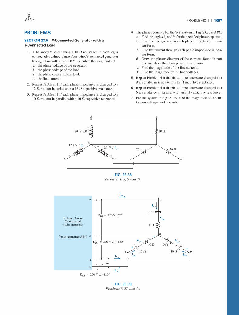
4. The phase sequence for the Y-Y system in Fig. 23.38 is ABC.a. Find the angles u2 and u3 for the specified phase sequence.b. Find the voltage across each phase impedance in pha-
sor form.c. Find the current through each phase impedance in pha-
sor form.d. Draw the phasor diagram of the currents found in part
(c), and show that their phasor sum is zero.e. Find the magnitude of the line currents.f. Find the magnitude of the line voltages.
5. Repeat Problem 4 if the phase impedances are changed to a9 � resistor in series with a 12 � inductive reactance.
6. Repeat Problem 4 if the phase impedances are changed to a6 � resistance in parallel with an 8 � capacitive reactance.
7. For the system in Fig. 23.39, find the magnitude of the un-known voltages and currents.
A
120 V �0°
a
20 �
20 �20 �
C B c b
120 V �03θ
+
–N
– 120 V �02θ
+
FIG. 23.38
Problems 4, 5, 6, and 31.
a
10 �
10 �
3-phase, 3-wireY-connected
4-wire generator
Phase sequence: ABC
10 �
Ian
n––
+
Van
IAa
A
EAB = 220 V ∠0°
EBC = 220 V ∠ + 120°
N
B
C
ECA = 220 V ∠ –120°
IBb
ICc
Icn Ibn
bc+
10 �
Vbn
–Vcn
+10 �
10 �
FIG. 23.39
Problems 7, 32, and 44.
boy30444_ch23.qxd 3/24/06 3:41 PM Page 1057
1058 ⏐⏐⏐ POLYPHASE SYSTEMS
+
EAB3-phase, 3-wireY-connected generator
A
B
C
1 �
Line resistance
a
16 �
12 �
n
12 �
16 �
c b
12 �
16 �V = 50 Vφ
–
1 �
1 �
FIG. 23.40
Problem 8.
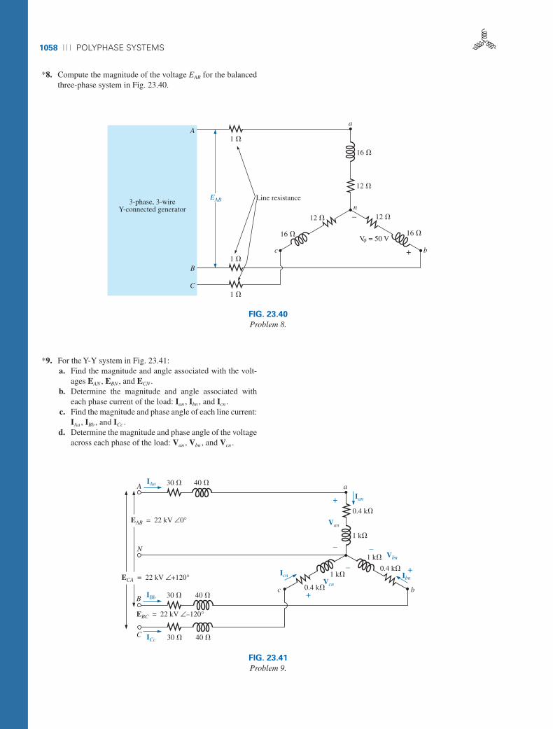
*8. Compute the magnitude of the voltage EAB for the balancedthree-phase system in Fig. 23.40.
*9. For the Y-Y system in Fig. 23.41:a. Find the magnitude and angle associated with the volt-
ages EAN , EBN , and ECN .b. Determine the magnitude and angle associated with
each phase current of the load: Ian , Ibn , and Icn .c. Find the magnitude and phase angle of each line current:
IAa , IBb , and ICc .d. Determine the magnitude and phase angle of the voltage
across each phase of the load: Van , Vbn , and Vcn .
A 30 �
+0.4 k�
N
B
C
30 �
EBC = 22 kV ∠–120°
40 �
30 � 40 �
IAa
IBb
ICc
ECA = 22 kV ∠+120°
EAB = 22 kV ∠0°
–
Van
Ian
1 k�
+
–Vbn1 k�
0.4 k�Ibn
bc
1 k�
+0.4 k�
Icn–
40 �
Vcn
a
FIG. 23.41
Problem 9.
boy30444_ch23.qxd 3/24/06 3:41 PM Page 1058

PROBLEMS ⏐⏐⏐ 1059
SECTION 23.6 Y-� System
10. A balanced � load having a 20 � resistance in each leg isconnected to a three-phase, three-wire, Y-connected gener-ator having a line voltage of 208 V. Calculate the magni-tude ofa. the phase voltage of the generator.b. the phase voltage of the load.c. the phase current of the load.d. the line current.
11. Repeat Problem 10 if each phase impedance is changed to a6.8 � resistor in series with a 14 � inductive reactance.
12. Repeat Problem 10 if each phase impedance is changedto an 18 � resistance in parallel with an 18 � capacitivereactance.
13. The phase sequence for the Y-� system in Fig. 23.42 is ABC.a. Find the angles u2 and u3 for the specified phase sequence.
b. Find the voltage across each phase impedance in pha-sor form.
c. Draw the phasor diagram of the voltages found in part (b),and show that their sum is zero around the closed loop ofthe � load.
d. Find the current through each phase impedance in pha-sor form.
e. Find the magnitude of the line currents.f. Find the magnitude of the generator phase voltages.
14. Repeat Problem 13 if the phase impedances are changed to a100 � resistor in series with a capacitive reactance of 100 �.
15. Repeat Problem 13 if the phase impedances are changed toa 3 � resistor in parallel with an inductive reactance of 4 �.
16. For the system in Fig. 23.43, find the magnitude of the un-known voltages and currents.
b22 �
c
a
B
N
C
A
EBC = 208 V ∠v2
ECA = 208 V ∠v3
EAB = 208 V ∠0°
22 � 22 �
FIG. 23.42
Problems 13, 14, 15, 34, and 45.
10 �10 �
a
10 �
3-phase, 3-wireY-connected
4-wire generator
Phase sequence: ABC
10 �
Ica
+
Vab
IAa
A
ECA = 220 V ∠ + 120°
B
C
EBC = 220 V ∠ –120°
IBb
ICc
bc
–
–
Vca
+
10 �
EAB = 220 V ∠0°
10 �
Iab
Ibc
Vbc +–
FIG. 23.43
Problems 16, 35, and 47.
boy30444_ch23.qxd 3/24/06 3:41 PM Page 1059
1060 ⏐⏐⏐ POLYPHASE SYSTEMS
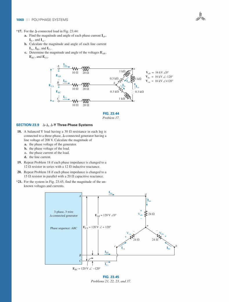
*17. For the �-connected load in Fig. 23.44:a. Find the magnitude and angle of each phase current Iab ,
Ibc , and Ica .b. Calculate the magnitude and angle of each line current
IAa , IBb , and ICc .c. Determine the magnitude and angle of the voltages EAB ,
EBC , and ECA .
SECTION 23.9 �-�, �-Y Three-Phase Systems
18. A balanced Y load having a 30 � resistance in each leg isconnected to a three-phase, �-connected generator having aline voltage of 208 V. Calculate the magnitude ofa. the phase voltage of the generator.b. the phase voltage of the load.c. the phase current of the load.d. the line current.
19. Repeat Problem 18 if each phase impedance is changed to a12 � resistor in series with a 12 � inductive reactance.
20. Repeat Problem 18 if each phase impedance is changed to a15 � resistor in parallel with a 20 � capacitive reactance.
*21. For the system in Fig. 23.45, find the magnitude of the un-known voltages and currents.
20 �10 �
+
–
20 �10 �
20 �10 �
1 k�
0.3 k� 1 k�
0.3 k�0.3 k�
1 k�
a
c
IAa
IBb
ICc
ECA
+
–EAB
B
+
–EBC
C
Ica
Iab
Ibcb
Vab = 16 kV ∠0°Vbc = 16 kV ∠–120°Vca = 16 kV ∠+120°
A
FIG. 23.44
Problem 17.
Van 24 �
A
B
C
a
n
bc
3-phase, 3-wireΔ-connected generator
Phase sequence: ABC
IBb
ICc
Icn Ibn
Ian
IAa
+
–
24 � 24 �
Vbn+
–
+
–Vcn
EBC = 120 V ∠ –120°
EAB = 120 V ∠0°
ECA = 120 V ∠ + 120°
FIG. 23.45
Problems 21, 22, 23, and 37.
boy30444_ch23.qxd 3/24/06 3:41 PM Page 1060

PROBLEMS ⏐⏐⏐ 1061
22. Repeat Problem 21 if each phase impedance is changed to a10 � resistor in series with a 20 � inductive reactance.
23. Repeat Problem 21 if each phase impedance is changed to a20 � resistor in parallel with a 15 � capacitive reactance.
24. A balanced � load having a 220 � resistance in each leg isconnected to a three-phase, �-connected generator having aline voltage of 440 V. Calculate the magnitude ofa. the phase voltage of the generator.b. the phase voltage of the load.c. the phase current of the load.d. the line current.
25. Repeat Problem 24 if each phase impedance is changed to a12 � resistor in series with a 9 � capacitive reactance.
26. Repeat Problem 24 if each phase impedance is changed to a22 � resistor in parallel with a 22 � inductive reactance.
27. The phase sequence for the �-� system in Fig. 23.46 is ABC.a. Find the angles u2 and u3 for the specified phase sequence.b. Find the voltage across each phase impedance in pha-
sor form.c. Draw the phasor diagram of the voltages found in part (b),
and show that their phasor sum is zero around the closedloop of the � load.
d. Find the current through each phase impedance in pha-sor form.
e. Find the magnitude of the line currents.
28. Repeat Problem 25 if each phase impedance is changed to a12 � resistor in series with a 16 � inductive reactance.
29. Repeat Problem 25 if each phase impedance is changed to a20 � resistor in parallel with a 20 � capacitive reactance.
SECTION 23.10 Power
30. Find the total watts, volt-amperes reactive, volt-amperes,and Fp of the three-phase system in Problem 2.
31. Find the total watts, volt-amperes reactive, volt-amperes,and Fp of the three-phase system in Problem 4.
32. Find the total watts, volt-amperes reactive, volt-amperes,and Fp of the three-phase system in Problem 7.
20 �
aA
BC
20 �
20 �c
ECA = 100 V ∠v3
EAB = 100 V ∠0°
EBC = 100 V ∠v2
b
FIG. 23.46
Problem 27.
boy30444_ch23.qxd 3/24/06 3:41 PM Page 1061
1062 ⏐⏐⏐ POLYPHASE SYSTEMS
33. Find the total watts, volt-amperes reactive, volt-amperes,and Fp of the three-phase system in Problem 12.
34. Find the total watts, volt-amperes reactive, volt-amperes,and Fp of the three-phase system in Problem 14.
35. Find the total watts, volt-amperes reactive, volt-amperes,and Fp of the three-phase system in Problem 16.
36. Find the total watts, volt-amperes reactive, volt-amperes,and Fp of the three-phase system in Problem 20.
37. Find the total watts, volt-amperes reactive, volt-amperes,and Fp of the three-phase system in Problem 22.
38. Find the total watts, volt-amperes reactive, volt-amperes,and Fp of the three-phase system in Problem 26.
39. Find the total watts, volt-amperes reactive, volt-amperes,and Fp of the three-phase system in Problem 28.
40. A balanced, three-phase, �-connected load has a line volt-age of 200 and a total power consumption of 4800 W at alagging power factor of 0.8. Find the impedance of eachphase in rectangular coordinates.
41. A balanced, three-phase,Y-connected load has a line voltageof 208 and a total power consumption of 1200 W at a lead-ing power factor of 0.6. Find the impedance of each phase inrectangular coordinates.
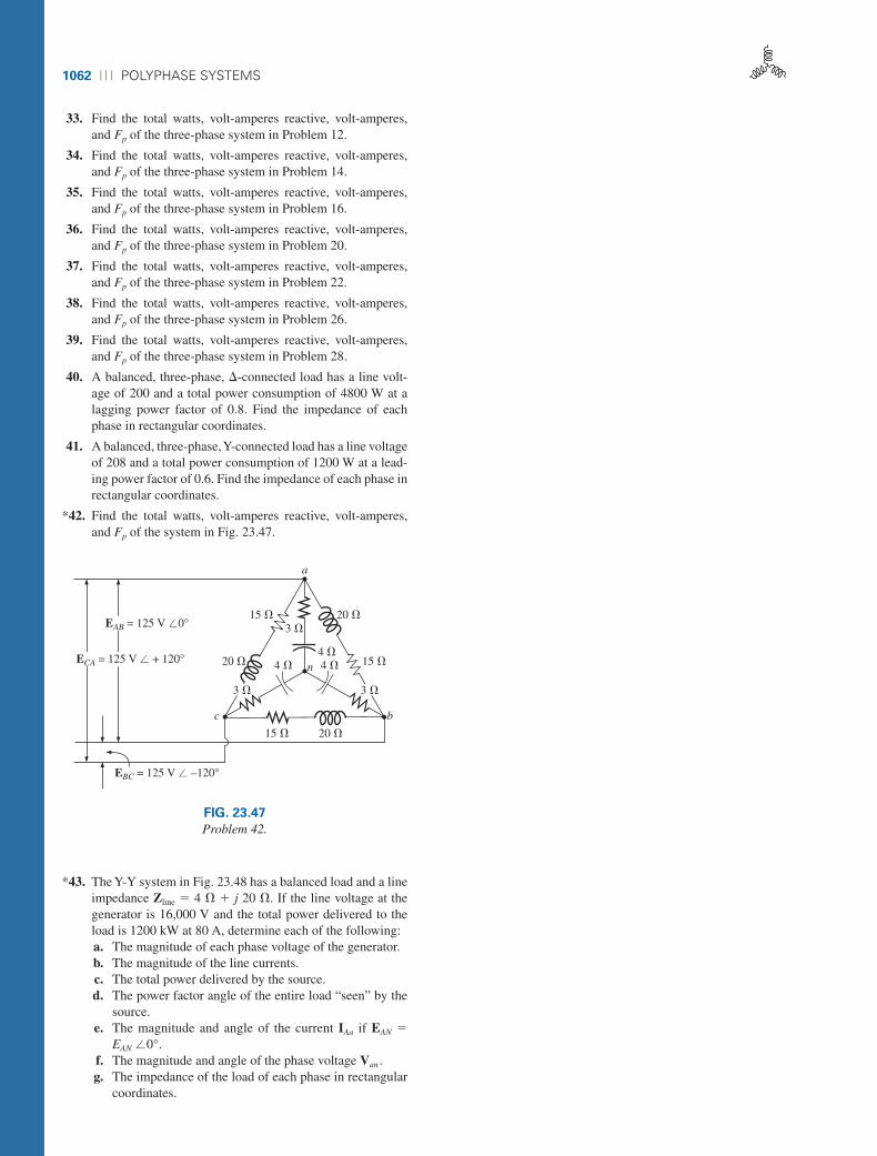
*42. Find the total watts, volt-amperes reactive, volt-amperes,and Fp of the system in Fig. 23.47.
*43. The Y-Y system in Fig. 23.48 has a balanced load and a lineimpedance Zline � 4 � � j 20 �. If the line voltage at thegenerator is 16,000 V and the total power delivered to theload is 1200 kW at 80 A, determine each of the following:a. The magnitude of each phase voltage of the generator.b. The magnitude of the line currents.c. The total power delivered by the source.d. The power factor angle of the entire load “seen” by the
source.e. The magnitude and angle of the current IAa if EAN �
EAN �0°.f. The magnitude and angle of the phase voltage Van .g. The impedance of the load of each phase in rectangular
coordinates.
a
20 �15 �3 �
4 � 4 �4 �
n 15 �
b
20 �15 �
3 �3 �
c
20 �
EBC = 125 V � –120°
ECA = 125 V � + 120°
EAB = 125 V �0°
FIG. 23.47
Problem 42.
boy30444_ch23.qxd 3/24/06 3:41 PM Page 1062

PROBLEMS ⏐⏐⏐ 1063
Z1
Z2 Z3
A
N
C B
IAa
EAB = 16 kV
4 � 20 �
4 � 20 �
4 � 20 �
c b
n
+
–
EAN
+
–
Van
aIan = 80 A
Z1 = Z2 = Z3
lagging Fp
FIG. 23.48
Problem 43.
h. The difference between the power factor of the load andthe power factor of the entire system (including Zline).
i. The efficiency of the system.
SECTION 23.11 Three-Wattmeter Method
44. a. Sketch the connections required to measure the totalwatts delivered to the load in Fig. 23.39 using threewattmeters.
b. Determine the total wattage dissipation and the readingof each wattmeter.
45. Repeat Problem 44 for the network in Fig. 23.42.
SECTION 23.12 Two-Wattmeter Method
46. a. For the three-wire system in Fig. 23.49, properly con-nect a second wattmeter so that the two measure the to-tal power delivered to the load.
b. If one wattmeter has a reading of 200 W and the other areading of 85 W, what is the total dissipation in watts ifthe total power factor is 0.8 leading?
c. Repeat part (b) if the total power factor is 0.2 laggingand Pl � 100 W.
47. Sketch three different ways that two wattmeters can be con-nected to measure the total power delivered to the load inProblem 16.
Δ- or Y-connected
load
+–+–
Wattmeter
CCPC
FIG. 23.49
Problem 46.
boy30444_ch23.qxd 3/24/06 3:41 PM Page 1063
1064 ⏐⏐⏐ POLYPHASE SYSTEMS
R3 10 �
ECA = 208 V ∠120°
+–+–
A
W1
+–+–
W2
B
C
IAa
IBb
ICc
–
+
EAB = 208 V ∠0°
EBC = 208 V ∠–120°
–
+
–
+
10 �XC
R1
R2
10 �
10 �
Iab
a
Ibc
Ica
c
b
10 �
XL
FIG. 23.50
Problem 48.
2 �
EBC = 208 V � –120°
ECA = 208 V � –240°
EAB = 208 V �0°
2 �
c b
n
10 �
10 �
12 �
12 �
a
FIG. 23.51
Problem 49.
EBC = 200 V � –120°
ECA = 200 V � –240°
EAB = 200 V �0°
20 �
c b
n
16 �
12 �
3 �
4 �
a
FIG. 23.52
Problem 50.
*48. For the Y-� system in Fig. 23.50:a. Determine the magnitude and angle of the phase currents.b. Find the magnitude and angle of the line currents.c. Determine the reading of each wattmeter.d. Find the total power delivered to the load.
SECTION 23.13 Unbalanced, Three-Phase, Four-Wire,
Y-Connected Load
*49. For the system in Fig. 23.51:a. Calculate the magnitude of the voltage across each
phase of the load.b. Find the magnitude of the current through each phase of
the load.c. Find the total watts, volt-amperes reactive, volt-
amperes, and Fp of the system.d. Find the phase currents in phasor form.e. Using the results of part (c), determine the current IN.
find the total watts, volt-amperes reactive, volt-amperes, andFp of the load.
GLOSSARY
�-connected ac generator A three-phase generator having thethree phases connected in the shape of the capital Greek letterdelta (�).
Line current The current that flows from the generator to theload of a single-phase or polyphase system.
Line voltage The potential difference that exists between thelines of a single-phase or polyphase system.
Neutral connection The connection between the generator andthe load that, under balanced conditions, will have zero currentassociated with it.
Phase current The current that flows through each phase of asingle-phase (or polyphase) generator or load.
Phase sequence The order in which the generated sinusoidalvoltages of a polyphase generator will affect the load to whichthey are applied.
Phase voltage The voltage that appears between the line andneutral of a Y-connected generator and from line to line in a�-connected generator.
SECTION 23.14 Unbalanced, Three-Phase,
Three-Wire, Y-Connected Load
*50. For the three-phase, three-wire system in Fig. 23.52, find themagnitude of the current through each phase of the load, and
boy30444_ch23.qxd 3/24/06 3:41 PM Page 1064

GLOSSARY ⏐⏐⏐ 1065
Polyphase ac generator An electromechanical source of acpower that generates more than one sinusoidal voltage per ro-tation of the rotor. The frequency generated is determined bythe speed of rotation and the number of poles of the rotor.
Single-phase ac generator An electromechanical source of acpower that generates a single sinusoidal voltage having a fre-quency determined by the speed of rotation and the number ofpoles of the rotor.
Three-wattmeter method A method for determining the totalpower delivered to a three-phase load using three wattmeters.
Two-wattmeter method A method for determining the totalpower delivered to a �- or Y-connected three-phase load us-ing only two wattmeters and considering the power factor ofthe load.
Unbalanced polyphase load A load not having the same imped-ance in each phase.
Y-connected three-phase generator A three-phase source of acpower in which the three phases are connected in the shape ofthe letter Y.
boy30444_ch23.qxd 3/24/06 3:41 PM Page 1065


![-134- US4665322 [A05] Nishimu Electronics Uninterruptible polyphase AC power supply US4665322 [A05] Nishimu Electronics Uninterruptible polyphase AC power.](https://static.fdocuments.us/doc/165x107/56649e1b5503460f94b0991a/-134-us4665322-a05-nishimu-electronics-uninterruptible-polyphase-ac-power.jpg)