An OFDM System Using Polyphase Filter and DFT … OFDM System Using Polyphase Filter and DFT...
18
NASA/TM--2001-210813 An OFDM System Using Polyphase Filter and DFT Architecture for Very High Data Rate Applications Muli Kifle and Monty Andro Glenn Research Center, Cleveland, Ohio Mark J. Vanderaar Efficient Channel Coding, Inc., Brooklyn Heights, Ohio May 2001 https://ntrs.nasa.gov/search.jsp?R=20010068891 2018-05-17T13:26:29+00:00Z
Transcript of An OFDM System Using Polyphase Filter and DFT … OFDM System Using Polyphase Filter and DFT...
NASA/TM--2001-210813
An OFDM System Using Polyphase Filter
and DFT Architecture for Very High Data
Rate Applications
Muli Kifle and Monty AndroGlenn Research Center, Cleveland, Ohio
Mark J. Vanderaar
Efficient Channel Coding, Inc., Brooklyn Heights, Ohio
May 2001
https://ntrs.nasa.gov/search.jsp?R=20010068891 2018-05-17T13:26:29+00:00Z

The NASA STI Program Office... in Profile
Since its founding, NASA has been dedicated tothe advancement of aeronautics and spacescience. The NASA Scientific and Technical
Information (STI) Program Office plays a key part
in helping NASA maintain this important role.
The NASA STI Program Office is operated by
Langley Research Center, the Lead Center forNASA's scientific and technical information. The
NASA STI Program Office provides access to the
NASA STI Database, the largest collection of
aeronautical and space science STI in the world.The Program Office is also NASA's institutional
mechanism for disseminating the results of its
research and development activities. These resultsare published by NASA in the NASA STI Report
Series, which includes the following report types:
TECHNICAL PUBLICATION. Reports of
completed research or a major significant
phase of research that present the results of
NASA programs and include extensive dataor theoretical analysis. Includes compilations
of significant scientific and technical data andinformation deemed to be of continuing
reference value. NASA's counterpart of peer-reviewed formal professional papers but
has less stringent limitations on manuscript
length and extent of graphic presentations.
TECHNICAL MEMORANDUM. Scientific
and technical findings that are preliminary orof specialized interest, e.g., quick release
reports, working papers, and bibliographiesthat contain minimal annotation. Does not
contain extensive analysis.
CONTRACTOR REPORT. Scientific and
technical findings by NASA-sponsored
contractors and grantees.
CONFERENCE PUBLICATION. Collected
papers from scientific and technicalconferences, symposia, seminars, or other
meetings sponsored or cosponsored byNASA.
SPECIAL PUBLICATION. Scientific,
technical, or historical information from
NASA programs, projects, and missions,
often concerned with subjects havingsubstantial public interest.
TECHNICAL TRANSLATION. English-
language translations of foreign scientificand technical material pertinent to NASA'smission.
Specialized services that complement the STIProgram Office's diverse offerings include
creating custom thesauri, building customizeddata bases, organizing and publishing research
results.., even providing videos.
For more information about the NASA STI
Program Office, see the following:
• Access the NASA STI Program Home Pageat http-[/www.sti.nasa.gov
• E-mail your question via the Internet [email protected]
• Fax your question to the NASA Access
Help Desk at 301-621-0134
• Telephone the NASA Access Help Desk at301-621-0390
Write to:
NASA Access Help DeskNASA Center for AeroSpace Information7121 Standard Drive
Hanover, MD 21076
NASA/TM--2001-210813
An OFDM System Using Polyphase Filter
and DFT Architecture for Very High Data
Rate Applications
Muli Kifle and Monty Andro
Glenn Research Center, Cleveland, Ohio
Mark J. Vanderaar
Efficient Channel Coding, Inc., Brooklyn Heights, Ohio
Prepared for the
19th International Communications Satellite Systems Conference and Exhibit
cosponsored by the AIAA, CNES, ESA, and SUPAERO
Toulouse, France, April 17-20, 2001
National Aeronautics and
Space Administration
Glenn Research Center
May 2001

NASA Center for Aerospace Information7121 Standard Drive
Hanover, MD 21076
Available from
National Technical Information Service
5285 Port Royal Road
Springfield, VA 22100
Available electronically at http://gltrs._c.nasa.gov/GLTRS
AN OFDM SYSTEM
USING POLYPHASE FILTER AND DFT ARCHITECTURE
FOR VERY HIGH DATA RATE APPLICATIONS
Muli Kite
NASA Glenn Research Center, MS 54-8
Cleveland, OH 44135 USA
Tel. 216-433-6521 Fax 216-433-8705
Monty AndroNASA Glenn Research Center, MS 54-8
Cleveland, OH 44135 USATel. 216-433-3492 Fax 216-433-8705
Mark J. Vanderaar
Efficient Channel Coding, Inc
Brooklyn Heights, OH 44131 USATel. 216.514.9516 Fax 216.514.9519
Abstract
This paper presents a conceptual architectural design of a four-channel Orthogonal Frequency
Division Multiplexing (OFDM) system with an aggregate information throughput of 622
megabits per second (Mbps). Primary emphasis is placed on the generation and detection of
the composite waveform using polyphase filter and Discrete Fourier Transform (DFT)
approaches to digitally stack and bandlimit the individual carriers. The four-channel approach
enables the implementation of a system that can be both power and bandwidth efficient, yet
enough parallelism exists to meet higher data rate goals. It also enables a DC power efficienttransmitter that is suitable for on-board satellite systems, and a moderately complex receiver
that is suitable for low-cost ground terminals. The major advantage of the system as compared
to a single channel system is lower complexity and DC power consumption. This is because the
highest sample rate is !6 that of the single channel system and synchronization can occur at
most, depending on the synchronization technique, 1,4the rate of a single channel system. The
major disadvantage is the increased peak-to-average power ratio over the single channel
system. Simulation results in a form of bit-error-rate (BER) curves are presented in this paper.
Introduction
A number of proposed broadband satellite communications systems feature rates at or in excess
of 622 Mbps per downlink with spectrum allocations generally being less than 500 MHz. This
requires the application of bandwidth and power efficient transmission techniques. Number of
approaches to implementing such techniques includes analog, digital, mixed signal systems,
single channel, or multi-channel. In general, the digital implementations offer more advantages.
However, fully digital implementation at data rates in excess of 622 Mbps is difficult due to the
high clock speeds that are required. For example, an uncoded 16-ary Quadrature Amplitude
Modulation (16QAM) system requires a symbol rate of about 156 Msymbols/sec to attain a
NASA/TM--2001-210813 I

throughput of 622Mbps. if four samplesper symbol areusedto generateand reconstructthewaveform,thesamplerate is622Msamples/sec.
In this paper,we examinethe useof multichannel techniquesasanotherway of reducing thesamplerate. Onesuchtechnique,Multi-Carrier Modulation (MCM) [7], divides thedata into anumber of low rate channelsthat arestackedin frequencyand separatedby 1/symbol rate.MCM, sometimesalsocalledOFDM, isbeingproposedfor numeroussystemsincluding mobilewirelessanddigital subscriberlink systems.
OFDM System Overview
The basic OFDM waveform in this paper is constructed by dividing an incoming data stream
into N=4 channels, each channel using Offset-16QAM. Each input channel symbol is denoted
xi, i=0,1,2,7 and is actually a complex number that is written as
Xi = a i q- jb i , i = 0,1,2,7
The reason the fourth channel is labeled 7 will become clear in the discrete time system. The
time domain waveform of each Offset-16QAM channel is thus written as
xi(t ) = a i (t)+ jb_(t- T� 2), i = 0,1,2,7 where T is the symbol rate. Each complex channel isthen filtered to limit the bandwidth of each channel.
This is written as
x i (t)* h(t) where h(t) is the filter function and the * denotes convolution.
Each complex channel is then stacked in frequency with carriers that are separated in frequency
by 1/T and are separated in phase by _ / 2. The complex carriers can thus be written as
2/)c_(t) = exp j t + i , i = 0,1,2,7
Each channel's modulated waveform is then
m r(t) = (x i (t) * h(t))c_ (t), i = 0,1,2,7 and the overall transmitted waveform is the summation
of all channels.
re(t)= __m,(t)= __, ((a_(t)+jb_(,)) h(t))exp ._ t+--iIz0,1,2,7 i=0,1,2,7 2
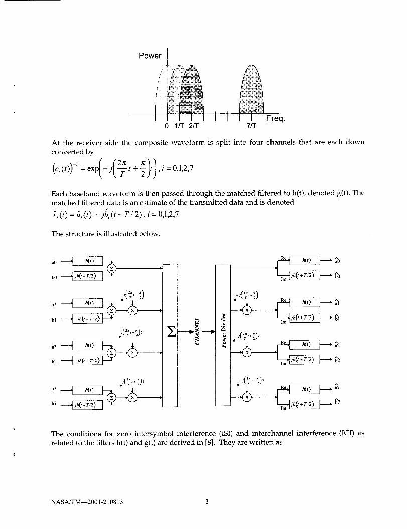
Pictorially, assuming a spectral shape for h(t), the frequency response of the compositewaveform is shown below.
NASA/TM--2001-210813 2
Power [L
I i I I/ I :1 I Freq.0 lfT 2/T 7/T
At the receiver side the composite waveform is split into four channels that are each down
converted by
( (2: 2))(c,(t))-' =exp -j t + ,i = 0,1,2,7
Each baseband waveform is then passed through the matched filtered to h(t), denoted g(t). Thematched filtered data is an estimate of the transmitted data and is denoted
Ji (t) = d i (t) + jb, (t - T� 2), i = 0,1,2,7
The structure is illustrated below.
a0 _ h(t) _-_ __ __ _ h(t) __ a"O"1 .
al ---q a(t) '_ '+_2)
bl _ jhq-T2)
2_t+g 2/(_ 2]
b: _'1 :h(,-_2)
/7;,+_),a7 _ h(t) _ :
b?___ j_(,__/_)
2E x
- _-_jh(,+r,2)
I
Aal
]--- _l
A
_ _t) _ a7
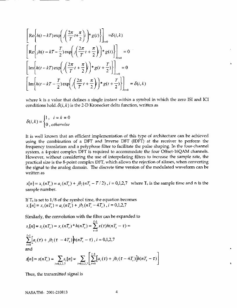
The conditions for zero intersymbol interference (ISI) and interchannel interference (ICI) as
related to the filters h(t) and g(t) are derived in [8]. They are written as
NASA/TM--2001-210813 3
Re h(t - kT- exp t + * g(t = 0
"J Jl=O
Im h(t-kT) exp j t+ i *g(t + =0
.'=0
Im h(t-kT-_)exp j Tt+ =t=0
where k is a value that defines a single instant within a symbol in which the zero ISI and ICI
conditions hold. _(i, k) is the 2-D Kronecker delta function, written as
1, i=k=06(i,k) = O,otherwise
It is well known that an efficient implementation of this type of architecture can be achieved
using the combination of a DFT and Inverse DFT (IDFT)at the receiver to perform the
frequency translation and a polyphase filter to facilitate the pulse shaping. In the four-channel
system, a 4-point complex DFT is required to accommodate the four Offset-16QAM channels.
However, without considering the use of interpolating filters to increase the sample rate, the
practical size is the 8-point complex DFT, which allows the rejection of aliases, when converting
the signal to the analog domain. The discrete time version of the modulated waveform can bewritten as
x[n] = x i (nT_) = a i (nT,) + jb i (nT, - T� 2), i = 0,1,2,7 where Ts is the sample time and n is the
sample number.
If Ts is set to 1/8 of the symbol time, the equation becomes
x, [n] = x, (nT,) = a, (nT,) + jb, (nT, - 4T,), i = 0,1,2,7
Similarly, the convolution with the filter can be expanded to1-1
s,[n] = s, (nT_ ) = x, (nT_ ) * h(nT_ ) = Z x( r)h(nT, - r) =r=0
1-1
y__,[ai(_) + jbi(1:'r=O
and
s[n]= s(nTs) =
- 4T_)_(nT_ - r), i = 0,1,2,7
'-' ]i=0,1,2,7 i=0,I,2,7
Thus, the transmitted signal is
NASA/TM--2001-210813 4
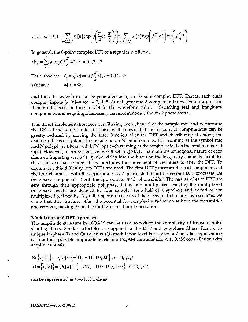
In general,the8-pointcomplexDFTof asignalis written as7
0, = Z _, exp(j 4 ki), k = 0,1,2...7i=0
7_
Thus if we set _. =si[n]exp(j_i), i = 0,1,2...7
We have re[n] = • _.
and thus the waveform can be generated using an 8-point complex DFT. That is, each eight
complex inputs (si [n]=0 for i= 3, 4, 5, 6) will generate 8 complex outputs. These outputs are
then multiplexed in time to obtain the waveform m[n]. "Switching real and imaginary
components, and negating if necessary can accommodate the rr / 2 phase shifts.
This direct implementation requires filtering each channel at the sample rate and performing
the DFT at the sample rate. It is also well known that the amount of computations can be
greatly reduced by moving the filter function after the DFT and distributing it among the
channels. In most systems this results in an N point complex DFT running at the symbol rate
and N polyphase filters with L/N taps each running at the symbol rate (L is the total number of
taps). However, in our system we use Offset-16QAM to maintain the orthogonal nature of each
channel. Imparting one half- symbol delay into the filters on the imaginary channels facilitates
this. This one half symbol delay precludes the movement of the filters to after the DFT. To
circumvent this difficulty two DFTs are used. The first DFT processes the real components of
the four channels (with the appropriate 7r / 2 phase shifts) and the second DFT processes the
imaginary components (with the appropriate rr / 2 phase shifts). The results of each DFT are
sent through their appropriate polyphase filters and multiplexed. Finally, the multiplexed
imaginary results are delayed by four samples (one half of a symbol) and added to the
multiplexed real results. A similar operation occurs at the receiver. In the next two sections, we
show that this structure offers the potential for complexity reduction at both the transmitter
and receiver, making it suitable for high-speed implementation.
Modulation and DFT Approach
The amplitude structure in 16QAM can be used to reduce the complexity of transmit pulse
shaping filters. Similar principles are applied to the DFT and polyphase filters. First, each
unique In-phase (I) and Quadrature (Q) modulation level is assigned a 2-bit label representing
each of the 4 possible amplitude levels in a 16QAM constellation. A 16QAM constellation with
amplitude levels
Re{x,[n]} = a,[n] _ {- 3.0,- 1.0, 1.0, 3.0}, i = 0,1,2,7
j Im{x_ [n]} = jb_[n] _ {- 3.0j,- 1.0j, 1.0j, 3.0j}, i = 0,1,2,7
can be represented as two bit labels as
NASA/TM--2001-210813 5
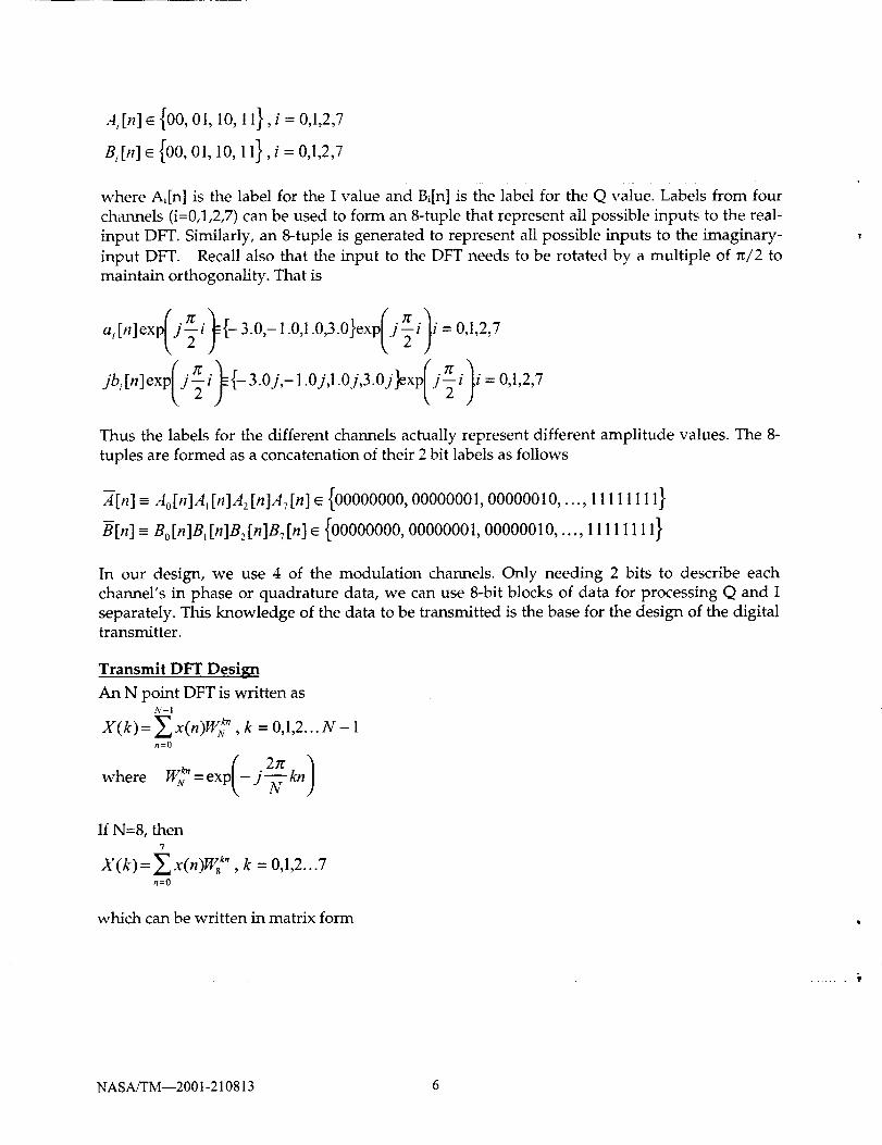
Ai[n]_ {00, 01, 10, 11},i = 0,1,2,7
B,[n] _ {00, 01, 10, 11} ,i = 0,I,2,7
where Ai[n] is the label for the I value and Bi[n] is the label for the Q value. Labels from four
channels (i=0,1,2,7) can be used to form an 8-tuple that represent all possible inputs to the real-
input DFT. Similarly, an 8-tuple is generated to represent all possible inputs to the imaginary-
input DFT. Recall also that the input to the DFT needs to be rotated by a multiple of r¢/2 to
maintain orthogonality. That is
a,[n]exp j-_t 3.0,-1.O,l.O,3.0}exp j_i i=0,1,2,7
jb,[n]exp(J2i_{-3.0j,-1.Oj,l.Oj,3.0j}exp(J2i)i=O,1,2,7
Thus the labels for the different channels actually represent different amplitude values. The 8-
tuples are formed as a concatenation of their 2 bit labels as follows
A-In]- Ao[n]A,[n]Az[n]Av[n ] _ {00000000, 00000001, 00000010, ..., 11111111}
B[.] = Bo[n]B,[n]B2[n]B7[. ] e {00000000, 00000001, 00000010 .... , lll11111}
In our design, we use 4 of the modulation channels. Only needing 2 bits to describe each
channel's in phase or quadrature data, we can use 8-bit blocks of data for processing Q and I
separately. This knowledge of the data to be transmitted is the base for the design of the digitaltransmitter.
Transmit DFT Design
An N point DFT is written asN-I
X(k)= Zx(n)Wt_ , k = 0,1,2... N- In=0
2z
where I'V_ = exp(- j--_- _77)
If N=8, then7
X(k)= Z x(n)W8 ", k = 0,1,2...7n=O
which can be written in matrix form
NASAfl'M--2001-210813 6
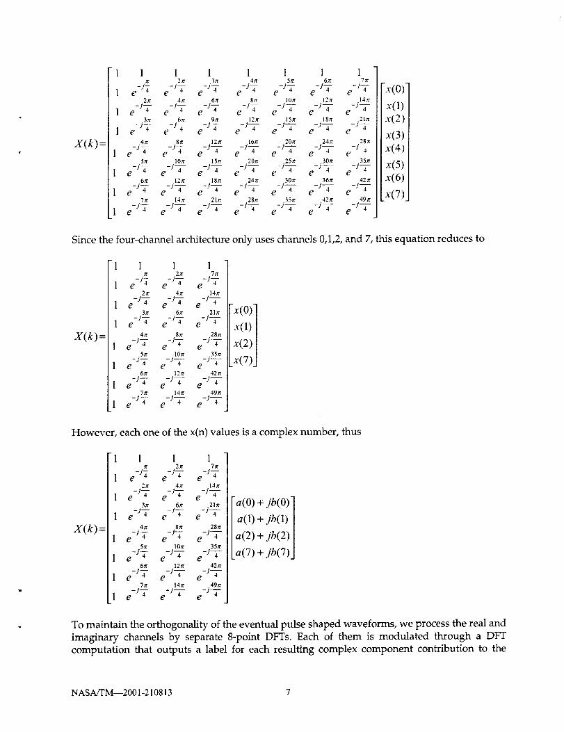
) =
1 l 1 1 1 1 1 17r 2zt 3rr 4It 5tr 6It 7x
- .... -- -iT1 e J4 e J4 e J4 e e -iT e -iT e -j-72re 4rt 61t' 8tr lOtr 12it 14re
_. .... ._ _j_- - .__ _ .__1 e J4 e J4 e J4 e -- e -j_- e J 4 e J 4
3zt 6n" 9_ 12a" 15ff 18zr .21zr
_. ...... j_- - .__ _ __1 C "14 e J4 e J4 e e -j-_- e J 4 e J 4
4x 8tr 12tr 16tr 20rr 24x 28it
e -j-i- e-tT e-J-g- e -jW- e-J--2- e-J-i- e-JW-5t¢ 10x 15zr 20r¢ 25it 30ff 35rr
[ e -j_- e-JW- e-J-2- e-J-7- e-J_ e -j-Z- e-J-T6.,'r 12 r¢ 18 zr 24 _ 30rr 36ff 42 x
1 e -sT e -j_- e -j-Y- e -j_- e -j-g- e -j-7- e -j_-7rr 14x 2In 28tr 35tr 42r¢ 49x
1 e -j-7 e j4 e J4 e j4 e J4 e J4 e J4
-x(0) l
x{l) l
x(2)l
x(3) t
x(411
x(5) l
x{O) l
x(7) l
Since the four-channel architecture only uses channels 0,1,2, and 7, this equation reduces to
X(k)=
1 1 1 1rc 2_r 7rr
1 e -j-2 e -iT e -j_-2re 4tr t4,'r
1 e -j_- e -iS- e-JW-3re 67r 2Dr
1 e -j--£ e -jY e -j--2-4_r 8/r 28z_
1 e Ja e;7 e JZ5zr 10n" 35yr
1 e-iT e-J-7 - e-J--£-6it 12tt 42x
1 e-Jz e-J_- e-JT7it 14re 49it
1 e -iS- e-J-7- e-J-T
x(o)]
x(l)]
x(2)[x(7)J
However, each one of the x(n) values is a complex number, thus
X(k) =
1 1 I 1tr 2n 7rt
1 e -j-g e -j--4- e-J-T2tr 4_r 14tt
1 e -j--g- e -iT e-J-z-3tr 6tt 2lit
1 e -sT e-iT e-l"-7-4a" 8tr 28ff
1 e -iT e -j-Z e-J--u5_ 10tr 35_
1 e-iT e-J-7 - e-J-T6rr 12it 42zt
1 e -j-T e -jW- e-l-7-7tr 14n" 49tt
1 e -j_- e -J_- e -j-7
a(O)+jb(O)]
a(1)+jb(1) I
a(2)+jb(2) I
a(7)+jb(7)J
To maintain the orthogonality of the eventual pulse shaped waveforms, we process the real and
imaginary channels by separate 8-point DFTs. Each of them is modulated through a DFT
computation that outputs a label for each resulting complex component contribution to the
NASA/TM--2001-210813 7
modulatedsignal.A bank of polyphasefilters takeseachoneof theseoutputsandtranslatesthelabels into 8-bit amplitude words. Theseare finally summed and the result is sent as themodulatedsignal.
IDFT Approach at the Receiver
On the receiver side, we will be able to separate the data's real and imaginary components. We
will then need to implement and efficient, straight computation of the IDFT. The Small-N
(N=8) DFT algorithm equations are an adaptation from those found on the handbook of Digital
Signal Processing [1]. The IDFT are computed by the following method:
IDFT by means of DFT; (1/N)X * (n) where X(n) is the DFT function and the * denotes a
conjugate operation.
The equations are expanded for an 8-point DFT for our specific case of separate real and
imaginary signal components. The result was a dual set of equations for the outputs of interest.
We take advantage of the LUT approach possible in FPGA devices by cutting down the
multiply operations. Since the amplitude data will have a finite length of 8 bits, we are able to
predict all possible amplitudes. Then instead of a traditional multiply operation, we will "look-
up" the result of the multiplication. On the receiving end we recuperate the original modulated
data for each of the four channels through an IDFT computation. This data is then passed on to
decoding and demodulation.
Polyphase Filters Design
In most OFDM systems, the modulated data is left unshaped with each channel having a
response that falls off as sin (Ts)/Ts. When the number of channels is large, this does not
adversely affect the overall system bandwidth efficiency. However, in this system where the
number of channels is only four, unshaped modulated data caused excessive bandwidth use.
To alleviate this situation shaping filters can be applied to limit the overall bandwidth.
However, this diversion from sinc functions in the frequency domain must be applied carefully
to limit intersymbol interference and maintain adjacent channel orthogonality.
From a hardware architectural view, the number of taps in the overall filter should be kept
small. Since the added complexity of interpolation filters is not warranted, the number of
samples per symbol is defined from the DFT size; in this case it is 8. Furthermore, the number
of symbols that the filter is defined over is set to two. This was chosen to limit the size of each
polyphase filter to two taps, which greatly eases the implementation complexity in FPGA. Thus
the overall filter is a 16-tap filter. In addition to the 16 taps constraint, the tilter must also limit
ISI and ICI. Generally speaking, the goals of shaping filter designs are to limit the bandwidth
without causing ISI using a limited number of taps. The root raised cosine (RRC) pulse is a
good candidate, but is not optimum. To get a truly optimum filter, one has to attempt to design
a filter that is both finite in time and in frequency, fundamentally an impossible task! To find
the coefficients of the filter, we first started with a truncated square root raised cosine (SRRC)
function [2].
The transmit polyphase filter uses the amplitude labels output from the DFT LUTs as input
addresses to groups of 16X8 LUTs that perform the coefficient multiply operations. There are
fundamentally two types of polyphase filter elements. The first is called the Small Polyphase
NASA/TM--2001-210813 8
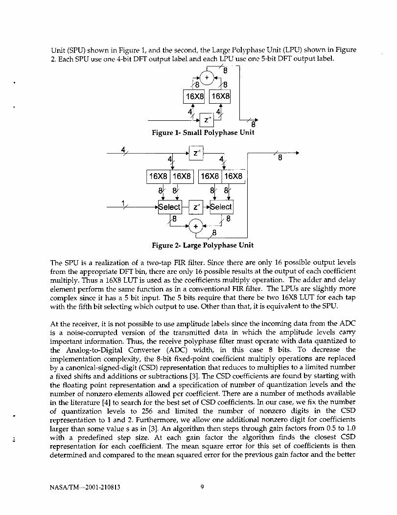
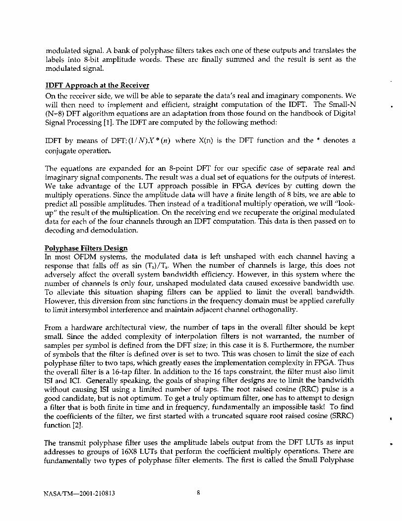
Unit (SPU)shownin Figure 1,and thesecond,theLargePolyphaseUnit (LPU)shownin Figure2.EachSPUuseone4-bitDFToutput labelandeachLPUuseone5-bitDFToutput label.
8
Figure 1-Small PolyphaseUnit
/
Figure 2- Large Polyphase Unit
The SPU is a realization of a two-tap FIR filter. Since there are only 16 possible output levels
from the appropriate DFT bin, there are only 16 possible results at the output of each coefficient
multiply. Thus a 16X8 LUT is used as the coefficients multiply operation. The adder and delay
element perform the same function as in a conventional FIR filter. The LPUs are slightly more
complex since it has a 5 bit input. The 5 bits require that there be two 16X8 LUT for each tap
with the fifth bit selecting which output to use. Other than that, it is equivalent to the SPU.
At the receiver, it is not possible to use amplitude labels since the incoming data from the ADC
is a noise-corrupted version of the transmitted data in which the amplitude levels carry
important information. Thus, the receive polyphase filter must operate with data quantized to
the Analog-to-Digital Converter (ADC) width, in this case 8 bits. To decrease the
implementation complexity, the 8-bit fixed-point coefficient multiply operations are replaced
by a canonical-signed-digit (CSD) representation that reduces to multiplies to a limited numbera fixed shifts and additions or subtractions [3]. The CSD coefficients are found by starting with
the floating point representation and a specification of number of quantization levels and the
number of nonzero elements allowed per coefficient. There are a number of methods available
in the literature [4] to search for the best set of CSD coefficients. In our case, we fix the number
of quantization levels to 256 and limited the number of nonzero digits in the CSD
representation to 1 and 2. Furthermore, we allow one additional nonzero digit for coefficients
larger than some value s as in [3]. An algorithm then steps through gain factors from 0.5 to 1.0
with a predefined step size. At each gain factor the algorithm finds the closest CSD
representation for each coefficient. The mean square error for this set of coefficients is then
determined and compared to the mean squared error for the previous gain factor and the better
NASA/TM--2001-210813 9
set of coefficients is kept. At the end, the best set of coefficients is kept. The quality of the
coefficients is determined by examining the spectral response of the CSD filter as compared to
the response of the floating-point version, and by inserting the CSD filter into a time domain
simulation that determines the BER using a semi-analytic approach.
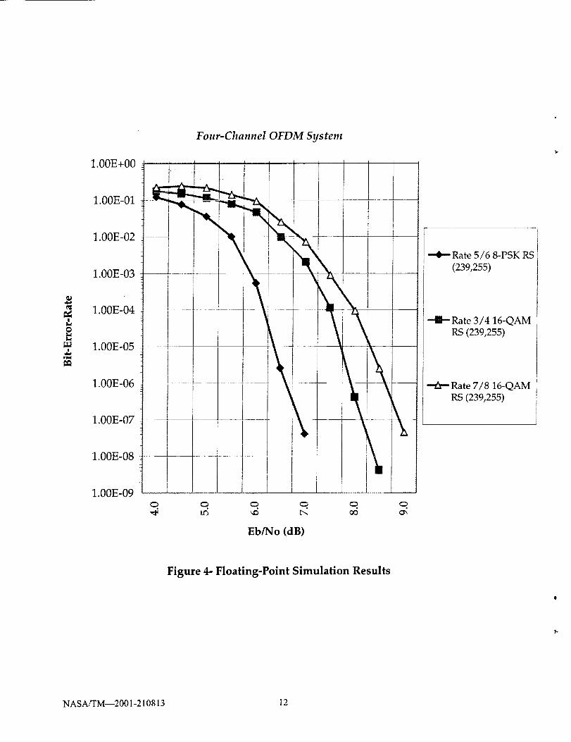
System Modeling and Simulations Results
An OFDM system model is being developed using the Signal Processing WorkStation tools.The basic OFDM waveform is constructed by dividing an incoming data stream into four
channels. The baseline rate 7/8 16QAM Four Dimensional Pragmatic Trellis Coded Modulation
(4D-PTCM) scheme [6] with a Reed-Solomon (RS) (255,239) is being developed for each of the
four channels. In addition to the baseline rate 7/8 16QAM, the trellis encoder also supports
rate 5/6 8-PSK and rate 3/4 16QAM. After trellis encoding, the bits are mapped into
modulation symbols represented by I- and Q-amplitude levels [5]. The bit to symbol mapping
is chosen in accordance with the encoding scheme to obtain the full benefit of TCM. We then
process each channel's modulated waveform through a DFT computation that produces a label
for each resulting complex component contribution to the modulated signal. The polyphase
filters takes these outputs and translates the labels into 8-bit amplitude words. These are finally
summed and the result is sent as the modulated signal. At the receiving end, since the
incoming data from the ADC is severely corrupted by noise, it is impossible to use amplitude
labels. Therefore, the receive polyphase filters (CSD) must take the data quantized to the ADC
width and process. We recover the original modulated data for each of the four channels
through an IDFT computation. The data is then passed on to decoding and demodulation.
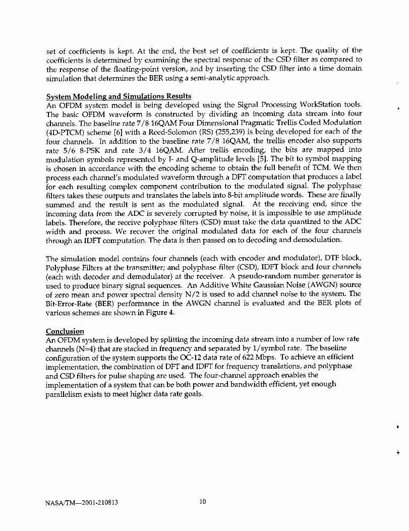
The simulation model contains four channels (each with encoder and modulator), DTF block,
Polyphase Filters at the transmitter; and polyphase filter (CSD), IDFT block and four channels
(each with decoder and demodulator) at the receiver. A pseudo-random number generator is
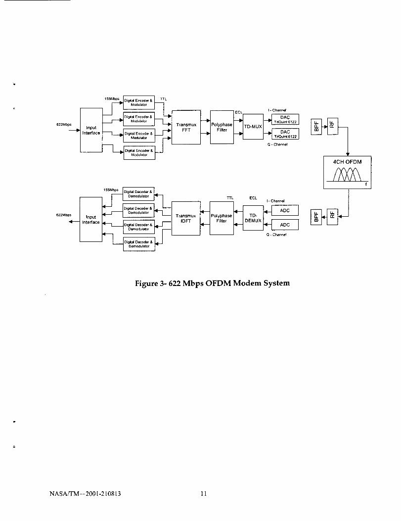
used to produce binary signal sequences. An Additive White Gaussian Noise (AWGN) source
of zero mean and power spectral density N/2 is used to add channel noise to the system. The
Bit-Error-Rate (BER) performance in the AWGN channel is evaluated and the BER plots of
various schemes are shown in Figure 4.
Conclusion
An OFDM system is developed by splitting the incoming data stream into a number of low rate
channels (N=4) that are stacked in frequency and separated by 1/symbol rate. The baseline
configuration of the system supports the OC-12 data rate of 622 Mbps. To achieve an efficient
implementation, the combination of DFT and IDFT for frequency translations, and polyphase
and CSD filters for pulse shaping are used. The four-channel approach enables the
implementation of a system that can be both power and bandwidth efficient, yet enough
parallelism exists to meet higher data rate goals.
NASA/TM--2001-210813 10
622Mbps
622Mbps
Digital Encode¢ &
Modulator
Modulator
MOdulator
Digital Encoder &
Modulator
Digital Decoder &
Demodulator
Demodulator
Demodulator
Transmux
FFT
Transmux
IDFT
_L I - Channel
DAC I
TriQuint 6122 I
•DAC I
TTL ECL
I _ I - Channe_
_--_ Pol_yphase _ ADC
___ PtlTerj_chaA_ c I
_r
4CH OFDM
Figure 3- 622 Mbps OFDM Modem System
NASAJTM--2001-210813 ll
Four-Channel OFDM System
1.00E+00 _ [_ : J /I
100 1.00E-02 j _t1.00E-03 - •
_ 1.00E-04 ....................... ! !-_
_, 1.00E-05 .... . --t
1.00E-06 - ---
1.00E-07 -
1.oo _o8....... --'r /1.00E-09 .................
Eb/No (dB)
--4_ Rate 5/6 8-PSK RS
(239,255)
Rate 3/4 16-QAMRS (239,255)
--A-- Rate 7/8 16-QAM
RS (239,255)
Figure 4- Floating-Point Simulation Results
NASA/TM--2001-210813 12
References
1. Elliott, Douglas F., "Handbook of Digital Signal Processing Engineering Applications",
Chapter 7: Fast Fourier Transforms, Appendix A: Small-N DFT Algorithms, p.597,
Academic Press, Inc., San Diego, CA 1987.
2. P. Chevellet, G. Ungerboeck, "Optimum FIR Transmitter and Receiver Filters for Data
Transmission over Band-Limited Channels", IEEE Trans. Comm., vol. COM-30, No. 8, Aug.1982.
3. Kim, Heechul, "Computer Simulation Results and Analysis for a Root-Raised Cosine Filter
design using Canonical Signed Digits", NASA Tech. Mem.107327, October 1996.
4. Q. Zhao and Y. Tadokoro, "A Simple Design of FIR Filters with Power-of-Two-
Coefficients", IEEE Transaction on Circuits and Systems, Vol. 35pp. 566-570, May 1988.
5. M. Kifle, et al, "Bounds and Simulation Results of 32-ary and 64-ary Quadrature Amplitude
Modulation for Broadband-ISDN via Satellite", NASA Tech. Mem. 106484, February 1994.
6. M. Vanderaar, et al, "A Low Complexity Encoder-Modulator for High Data Rate Satellite
BISDN Applications", MILCOM '96, McLean VA, October 1996.
7. H.F. Harmuth, "On the Transmission of Information by Orthogonal Time Functions", AIEE
Trans. (Commun. Electron.), vol. 79, pp. 248-255, July 1960.
8. A. Vahlin and N. Holte, "Optimal Finite Duration Pulse For OFDM', IEEE Transactions on
Communications, Volume: 44 Issue: 1, January 1996.
NASA/TM--2001-210813 13
Form ApprovedREPORT DOCUMENTATION PAGEOMB No. 0704-0188
Pubflc reporting burden for this collection of information is estimated to average I hour per response, including the time for reviewing Instructions, searching existing data sources,gathering and maintaining the data needed, and completing and reviewing the collection of information. Send comments regarding this burden estimate or any other aspect of thiscollection of information, including suggestions for reducing this burden, to Washington Headquarters Services, Directorate for Information Operations and Reports, 1215 JeffersonDavis Highway, Suite 1204, Arlington, VA 22202-4302, and to the Office of Management and Budget, Paperwork Reduction Project (0704-0188), Washington, DC 20503.
,1. AGENCY USE ONLY (Leave blank) 2. REPORT DATE 3. REPORT TYPE AND DATES COVERED
May 2001 Technical Memorandum
4. TITLE AND SUBTITLE
An OFDM System Using Polyphase Filter and DF'lr" Architecture for
Very High Data Rate Applications
6. AUTHOR(S)
Muli Kifle, Monty Andro, and Mark J. Vanderaar
7. PERFORMING ORGANIZATION NAME(S) AND ADDRESS(ES)
National Aeronautics and Space Administration
John H. Glenn Research Center at Lewis Field
Cleveland, Ohio 44135 -3191
9. SPONSORING/MONITORING AGENCY NAME(S) AND ADDRESS(ES)
National Aeronautics and Space Administration
Washington, DC 20546-0001
5. FUNDING NUMBERS
WU-755-O8-0B-00
8. PERFORMING ORGANIZATIONREPORT NUMBER
E-12728
!10. SPONSORING/MONITORINGAGENCY REPORTNUMBER
NASA TM--2001-210813
11. SUPPLEMENTARY NOTES
Prepared for the 19th International Communications Satellite Systems Conference and Exhibit cosponsored by the AIAA,
CNES, ESA, and SUPAERO, Toulouse, France, April 17-20, 2001. Mull Kifle and Monty Andro, NASA Glenn Research
Center, and Mark J. Vanderaar, Efficient Channel Coding, Inc., Brooklyn Heights, Ohio 44131. Responsible person, Mull
Kifle, organization code 5650, 216--433-6521.
12a. DISTRIBUTION/AVAILABILITY STATEMENT
Unclassified - Unlimited
Subject Category: 32 Distribution: Nonstandard
Available electronically at htm://_ltrs.m'c.nasa._ov/GLTRS
This publication is available from the NASA Center for AeroSpace Information. 301-621-0390.
12b. DISTRIBUTION CODE
13. ABSTRACT (Maximum 200 words)
This paper presents a conceptual architectural design of a four-channel OFDM system with an aggregate information
throughput of 622 megabits per second (Mbps). Primary emphasis is placed on the generation and detection of the
composite waveform using polyphase filter and Discrete Fourier Transform (DFT) approaches to digitally stack and
bandlimit the individual carriers. The four-channel approach enables the implementation of a system that can be both
power and bandwidth efficient, yet enough parallelism exists to meet higher data rate goals. It also enables a DC power
efficient transmitter that is suitable for on-board satellite systems, and a moderately complex receiver that is suitable for
low-cost ground terminals. The major advantage of the system as compared to a single channel system is lower complex-
ity and DC power consumption. This is because the highest sample rate is 1/2 that of the single channel system and
synchronization can occur at most, depending on the synchronization technique, 1/4 the rate of a single channel system.
The major disadvantage is the increased peak-to-average power ratio over the single channel system. Simulation results in
a form of bit-error-rate (BER) curves are presented in this paper.
14. SUBJECT TERMS
Communications
17. SE(_URITY CLASSIFICATIONOF REPORT
Unclassified
NSN 7540-01-280-5500
18. SECURITY CLASSIFICATIONOF THIS PAGE
Unclassified
19. SECURITY CLASSIFICATIONOF ABSTRACT
Unclassified
15. NUMBER OF PAGES19
16. PRICE CODE
20. LIMITATION OF ABSTRACT
Standard Form 298 (Rev. 2-89)PrescribedbyANSI Std.Z39-1829B-102