Pocket Colorimeter II Test Kit - DelAgua · 2015-02-26 · The instrument cap for the Pocket...
72
59574-88 Pocket Colorimeter™II Test Kit Immunoassay Instruction Manual Alachlor and Atrazine in Water PCB in Soil TPH in Soil and Water © Hach Company, 2003—2006. All rights reserved. jk/dk 10/06 2ed
Transcript of Pocket Colorimeter II Test Kit - DelAgua · 2015-02-26 · The instrument cap for the Pocket...
59574-88
Pocket Colorimeter™II Test Kit
Immunoassay Instruction ManualAlachlor and Atrazine in Water
PCB in SoilTPH in Soil and Water
© Hach Company, 2003—2006. All rights reserved. jk/dk 10/06 2ed

1—2
1—3
Table of Contents
Safety Precautions ................................................................................................................. 1—5Laboratory Safety .............................................................................................................. 1—5Use of Hazard Information............................................................................................... 1—5Precautionary Labels ......................................................................................................... 1—5
Specifications .......................................................................................................................... 1—7Instrument Keys and Display ............................................................................................... 1—7Instrument Cap Cord ............................................................................................................. 1—8
Operation.................................................................................................................................. 1—9Data Sheet ............................................................................................................................. 1—10
Chapter 1 Procedure for Alachlor in Water .................................................................. 1—11Immunoassay ...................................................................................................................1—12Color Development ..........................................................................................................1—14Measuring the Color ........................................................................................................1—14
Chapter 2 Procedure for Atrazine in Water ..................................................................1—19Immunoassay ...................................................................................................................1—21Color Development ..........................................................................................................1—23Measuring the Color ........................................................................................................1—24Required Reagents ...........................................................................................................1—28
Chapter 3 Procedure for PCB in Soil ...............................................................................1—29Immunoassay ...................................................................................................................1—32Color Development ..........................................................................................................1—34Measuring the Color ........................................................................................................1—35
Chapter 4 Procedure for TPH in Soil and Water ..........................................................1—39Immunoassay ...................................................................................................................1—42Color Development ..........................................................................................................1—44Measuring the Color ........................................................................................................1—45
Section 2 Instrument Manual ............................................................................................. 2—1Accessories ............................................................................................................................... 2—3
The 1-cm MicroCuvette Rack........................................................................................... 2—3Using the Precision Pipettor............................................................................................. 2—4Using the WireTrol™ Pipet ................................................................................................ 2—4
1—4
Table of Contents, continued
Instrument Operation............................................................................................................ 2—5Key Functions .................................................................................................................... 2—5Menu Selections................................................................................................................. 2—5Switching Ranges .............................................................................................................. 2—5Setting the Time ................................................................................................................ 2—5Recalling Stored Measurements....................................................................................... 2—5Battery Installation............................................................................................................ 2—6
Error Codes .............................................................................................................................. 2—7Error Messages ................................................................................................................... 2—7
Standard Calibration Adjust ................................................................................................ 2—9User-Entered Calibration ....................................................................................................2—11
Overview........................................................................................................................... 2—11Calibration Procedure Using Prepared Standards ....................................................... 2—12Entering a Predetermined Calibration Curve ............................................................... 2—13Editing a User-entered or Factory Calibration Curve ................................................. 2—14Exiting the Calibration Routine..................................................................................... 2—15Deleting Calibration Points ............................................................................................ 2—15Retrieving the Factory Calibration................................................................................ 2—16Maximum/Minimum Displayed Value.......................................................................... 2—16
Certification .......................................................................................................................... 2—17
General Information ............................................................................................................ 2—19How To Order ........................................................................................................................ 2—20Repair Service ....................................................................................................................... 2—21Warranty ................................................................................................................................ 2—22

1—5
Safety PrecautionsPlease read this entire manual before unpacking, setting up, or operating this instrument. Pay particular attention to all danger and caution statements. Failure to do so could result in serious injury to the operator or damage to the equipment.
To ensure the protection provided by this equipment is not impaired, do not use or install this equipment in any manner other than that which is specified in this manual.
Laboratory SafetyAs part of good laboratory practice, please familiarize yourself with the reagents used in these procedures. Read all product labels and the material safety data sheets (MSDS) before using them. It is always good practice to wear safety glasses when handling chemicals. Follow instructions carefully. Rinse thoroughly if contact occurs. If you have questions about reagents or procedures, please contact the manufacturer.
Use of Hazard InformationIf multiple hazards exist, this manual will use the signal word (Danger, Caution, Note) corresponding to the greatest hazard.DANGERIndicates a potentially or imminently hazardous situation which, if not avoided, could result in death or serious injury.CAUTIONIndicates a potentially hazardous situation that may result in minor or moderate injury.NOTEInformation that requires special emphasis.
Precautionary LabelsRead all labels and tags attached to the instrument. Personal injury or damage to the instrument could occur if not observed.
This symbol, if noted on the instrument, references the instruction manual for operational and/or safety information.

1—6

1—7
SpecificationsLamp: Light emitting diode (LED)
Detector: Silicon photodiode
Photometric Precision: ±0.0015 Absorbance
Filter bandwidth: 15 ±2 nm
Wavelength: 450 nm
Absorbance range: 0 to 2.50 Abs
Dimensions: 3.2 x 6.1 x 15.2 cm (1.25 x 2.4 x 6 inches)
Weight: 0.2 kg (0.43 lbs)
Sample cells: 1 cm cuvette
Operating conditions: 0 to 50 °C (32 to 122 °F); 0 to 90% relative humidity (noncondensing)
Power supply: Four AAA alkaline batteries; approximate life is 2000 tests*
Instrument Keys and Display
* Backlight usage will decrease battery life.
Item Description
1 POWER Key
2 ZERO/SCROLL Key
3 MENU Key
4 Numeric Display
5 Range Indicator
6 Range Indicator
7 Menu Indicator
8 Calibration Adjusted Indicator
9 Battery Low Indicator
10 READ/ENTER Key

1—8
Instrument Cap CordThe instrument cap for the Pocket Colorimeter™ II doubles as a light shield. Accurate measurements cannot be obtained unless the sample or blank is covered with the cap. Use the instrument cap cord to secure the cap to the body of the colorimeter and prevent loss of the cap. See Figure 1.
1. Loop the instrument cap cord through the ring on the cap.
2. Remove the battery compartment cover. Press the knotted end of the cord into the hole indicated by the arrow.
3. Slide the cord into the slot on the battery compartment cover. Snap the cover into place.
Figure 1 Attaching the Instrument Cap Cord

1—9
DANGERHandling chemical samples, standards, and reagents can be dangerous. Review the necessary Material Safety Data Sheets and become familiar with all safety procedures before handling any chemicals.
DANGERLa manipulation des échantillons chimiques, étalons et réactifs peut être dangereuse. Lire les Fiches de Données de Sécurité des Produits (FDSP) et se familiariser avec toutes les procédures de sécurité avant de manipuler tous les produits chimiques.
PELIGROLa manipulación de muestras químicas, estándares y reactivos puede ser peligrosa. Revise las fichas de seguridad de materiales y familiarícese con los procedimientos de seguridad antes de manipular productos químicos.
GEFAHRDas Arbeiten mit chemischen Proben, Standards und Reagenzien ist mit Gefahren verbunden. Es wird dem Benutzer dieser Produkte empfohlen, sich vor der Arbeit mit sicheren Verfahrensweisen und dem richtigen Gebrauch der Chemikalien vertraut zu machen und alle entsprechenden Materialsicherheitsdatenblätter aufmerksam zu lesen.
PERIGOA manipulação de amostras, padrões e reagentes químicos pode ser perigosa. Reveja a folha dos dados de segurança do material e familiarize-se com todos os procedimentos de segurança antes de manipular quaisquer produtos químicos.
PERICOLOLa manipolazione di campioni, standard e reattivi chimici può essere pericolosa. La preghiamo di prendere conoscenza delle Schede Techniche necessarie legate alla Sicurezza dei Materiali e di abituarsi con tutte le procedure di sicurezza prima di manipolare ogni prodotto chimico.
Operation

1—10
Data Sheet*
Location:Date of Testing:Operator:Lot Number of Reagent Set:Serial Number of Immunoassay Pocket Colorimeter:
* This page may be duplicated as needed.
CALIBRATORS
Calibrator Value Absorbance Comments
SAMPLES
Sample Number Absorbance Interpretation Comments

1—11
Chapter 1 Procedure for Alachlor in Water
1.1 OverviewAlachlor is a widely-used herbicide for the control of grasses and broadleaf weeds. It is sold by several companies under a variety of trade names. The Maximum Contaminant Level for Alachlor in the United States has been set at 2 parts per billion (ppb) by the U.S. Environmental Protection Agency.
Samples, calibrators, and reagents are added to cuvettes coated with antibodies specific for Alachlor. The resultant color is measured with a Hach Pocket Colorimeter II. The concentration of Alachlor in a sample is determined by comparing the developed color intensity to that of an Alachlor calibrator. The Alachlor concentration is inversely proportional to the color development: the lighter the color, the higher the Alachlor concentration.
This method provides semi-quantitative screening based on thresholds for Alachlor in the following concentrations: 0.1 ppb and/or 0.5 ppb. Other concentrations of Alachlor in water can be tested by first diluting the sample with deionized water. (See Diluting Water Samples on page 1—17.)
1.2 Testing Hints1. Read the entire procedure before starting. Identify and
have ready all the necessary reagents, cuvettes, and other apparatus before beginning the analysis.
2. Timing is critical; follow instructions carefully.3. A consistent technique when mixing the cuvettes is
critical to this test. Using the cuvette rack and mixing, as described in The 1-cm MicroCuvette Rack on page 2—3, yields the best results. Cuvettes can be mixed individually, but test results may not be as consistent.
4. The test requires about 30 minutes for complete analysis. As many as 20 cuvettes (18 samples and 2 calibrators) can be run simultaneously.
5. Handle the cuvettes carefully. Scratches on the inside or outside may cause erroneous results. Gently clean the outside of the cuvettes with a clean absorbent cloth or tissue before placing them into the instrument. (Kimwipe® tissues are provided with the kit.)
6. Antibody cuvettes and enzyme conjugate are manufactured in matched lots. Do not mix reagent lots.
1—12
Chapter 1, continued
7. Twenty Antibody Cuvettes are provided with each reagent set. One Antibody Cuvette will be used for each calibrator and each sample. Antibody Cuvettes are not reusable.
8. The Immunoassay Pocket Colorimeter provides a reading in absorbance units. This unit of measurement will allow you to compare your samples to the calibrators.
9. To avoid damaging the Color Developing Solution, do not expose it to direct sunlight.
10. Store the reagents at 4 °C when they are not in use. Allow the reagents to reach room temperature before using them in an analysis. Actual testing may be done at temperatures ranging from 1 °C to 38 °C.
1.3 Procedure
Immunoassay
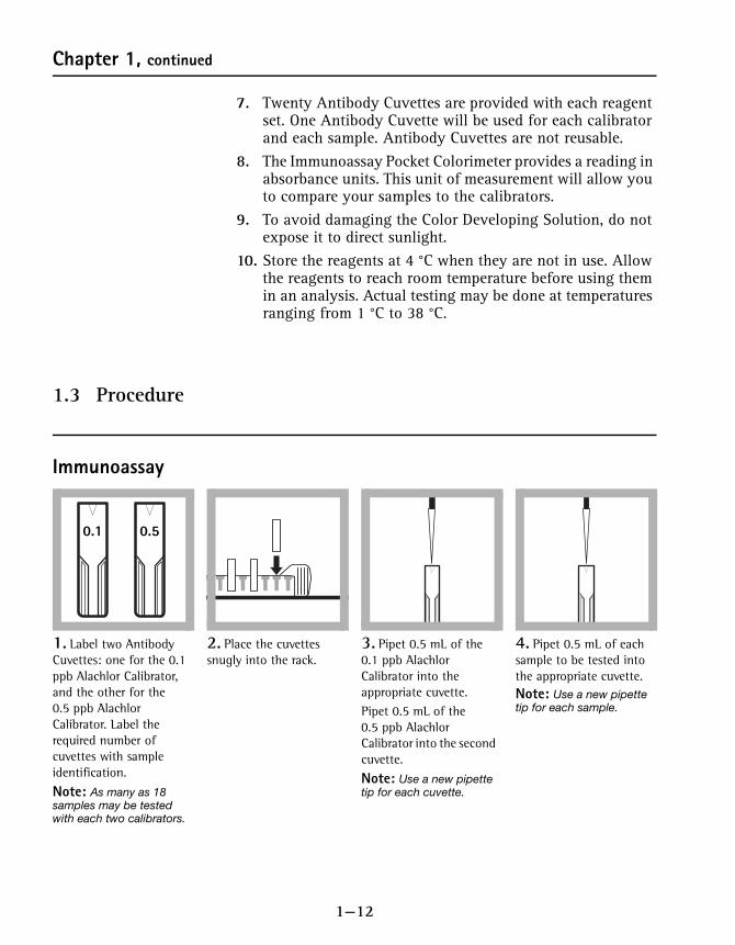
1. Label two Antibody Cuvettes: one for the 0.1 ppb Alachlor Calibrator, and the other for the 0.5 ppb Alachlor Calibrator. Label the required number of cuvettes with sample identification.
Note: As many as 18 samples may be tested with each two calibrators.
2. Place the cuvettes snugly into the rack.
3. Pipet 0.5 mL of the 0.1 ppb Alachlor Calibrator into the appropriate cuvette. Pipet 0.5 mL of the 0.5 ppb Alachlor Calibrator into the second cuvette.
Note: Use a new pipette tip for each cuvette.
4. Pipet 0.5 mL of each sample to be tested into the appropriate cuvette.Note: Use a new pipette tip for each sample.
0.1 0.5
1—13
Chapter 1, continued
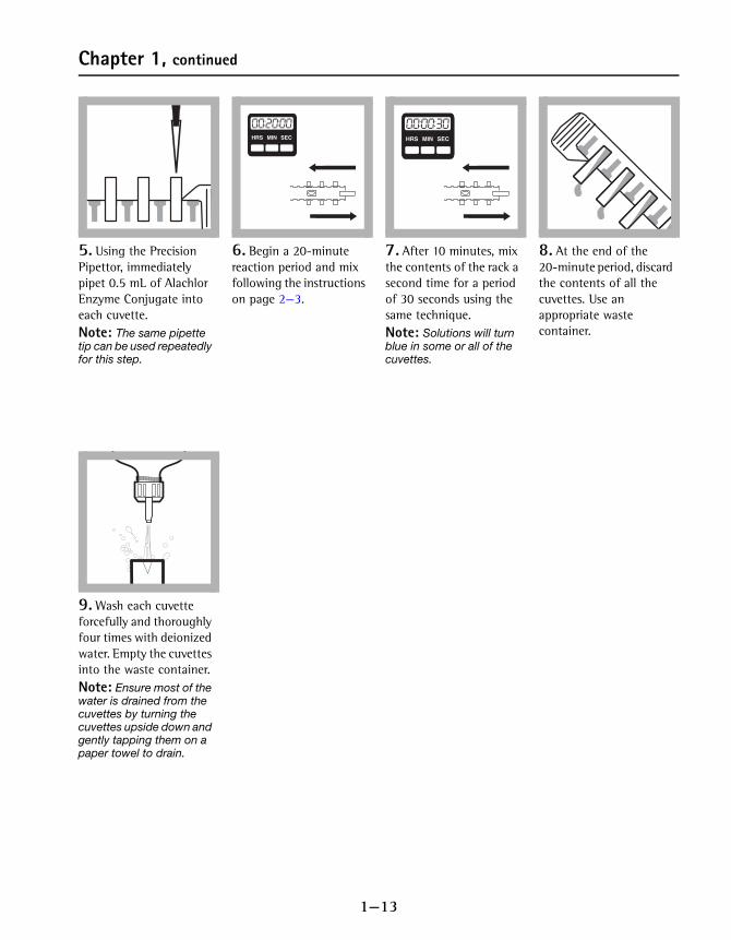
5. Using the Precision Pipettor, immediately pipet 0.5 mL of Alachlor Enzyme Conjugate into each cuvette.Note: The same pipette tip can be used repeatedly for this step.
6. Begin a 20-minute reaction period and mix following the instructions on page 2—3.
7. After 10 minutes, mix the contents of the rack a second time for a period of 30 seconds using the same technique.Note: Solutions will turn blue in some or all of the cuvettes.
8. At the end of the 20-minute period, discard the contents of all the cuvettes. Use an appropriate waste container.
9. Wash each cuvette forcefully and thoroughly four times with deionized water. Empty the cuvettes into the waste container.Note: Ensure most of the water is drained from the cuvettes by turning the cuvettes upside down and gently tapping them on a paper towel to drain.
HRS MIN SECHRS MIN SEC HRS MIN SECHRS MIN SEC

1—14
Chapter 1, continued
Color DevelopmentNote: Timing is critical; follow instructions carefully.
Measuring the Color
10. With the cuvettes still held snugly in the rack, pipet 0.5 mL of Color Developing Solution into each Antibody Cuvette.Note: Use a new pipette tip for each cuvette.
11. Begin a 10-minute reaction period and mix following the instructions on page 2—3.
12. After 5 minutes, mix the contents of the rack a second time for a period of 30 seconds using the same technique.Note: Solutions will turn blue in some or all of the cuvettes.
13. At the end of the 10-minute reaction period, pipette 0.5 mL of Stop Solution into each cuvette in the same order as the Color Developing Solution was added. Slide the rack for 20 seconds using the technique described on page 2—3.
Note: Blue solutions will turn yellow with the addition of the Stop Solution.
Note: The same pipette tip can be used repeatedly for this step.
1. Label and fill a Zeroing Cuvette with deionized water. Wipe the outside of all the cuvettes with a tissue to remove water, smudges, and fingerprints.
2. Insert the Zeroing Cuvette into the 1-cm micro-cuvette cell holder. Cover the zeroing cuvette with the instrument cap.Note: The arrow at the top of the cuvette should always face the display.
3. Press the POWER key to turn the meter on. The arrow can indicate either channel 1 or 2 for this method.Note: A user calibration should not be stored in the channel that you choose to use.
4. Press: ZERO/SCROLL. The instrument display will turn on and the display will show “---”, followed by “0.000”.
HRS MIN SECHRS MIN SEC HRS MIN SECHRS MIN SEC
DI

1—15
Chapter 1, continued
1.4 Interpreting the ResultsThere is an inverse relationship between the concentration of Alachlor and the absorbance. In other words, the higher the absorbance value, the lower the concentration of Alachlor.
Example:
0.1 ppb Alachlor Calibrator: 0.450 Abs.
0.5 ppb Alachlor Calibrator: 0.230 Abs.
Sample #1: 0.150 Abs.
Sample #2: 0.350 Abs.
Sample #3: 0.550 Abs.
Sample #1 — Sample absorbance is less than the absorbance for both calibrators. Therefore the sample concentration is greater than 0.1 and greater than 0.5 ppb Alachlor.
5. Remove the zeroing cuvette and insert the 0.1 ppb Alachlor calibrator into the cell holder. Cover the cuvette with the instrument cap.
6. Press: READ/ENTER. Record the absorbance value displayed.
7. Repeat step 5 and step 6 for all remaining calibrators and samples.Record the absorbance value of each calibrator and sample. A Data Sheet (page 1—10) has been provided that may be photocopied and used for each set of tests.
RepeatSteps 18—19
If the sample absorbance is… Sample Alachlor Concentration is…
…less than calibrator absorbance …greater than the calibrator value
…greater than calibrator absorbance …less than the calibrator value
1—16
Chapter 1, continued
Sample #2 — Sample absorbance is between the absorbance for the 0.1 and 0.5 ppb Alachlor calibrators. Therefore the concentration of Alachlor is between 0.1 and 0.5 ppb Alachlor.
Sample #3 — Sample absorbance is greater than the absorbance for both calibrators. Therefore the sample concentration is less than 0.5 ppb and less than 0.1 ppb Alachlor.
1.5 Storing and Handling Reagents• Wear protective gloves and eyewear.
• When storing reagent sets for extended periods of time,keep them out of direct sunlight. Reagent shelf life can be extended by refrigerating the reagents and is strongly recommended.
• Keep the foil pouch containing the Alachlor Antibody Cuvettes sealed when not in use.
• If Stop Solution comes in contact with eyes, wash thoroughly for 15 minutes with cold water and seek immediate medical help.
1.6 SensitivityThe Alachlor immunoassay test cannot differentiate between the various acetanilide herbicides and metabolites, but it detects their presence to differing degrees. The following table shows the required concentration for selected chemicals.
The following compounds are not detectable at 10,000 ppb:
CompoundConcentration required to give a positive response of
0.1 ppb Alachlor
Concentration required to give a positive response of
0.5 ppb AlachlorAcetochlor 0.45 ppb 4 ppb
Butachlor 0.09 ppm 1 ppm
2 Chloro-2’,6’-Diethylacetaniline 0.030 ppm 2 ppm
Metolachlor 0.085 ppm 2 ppm
2,6-Diethylaniline 0.3 ppm 9 ppm
Propachlor 0.72 ppm 12 ppm
Atrazine Carbofuran Carbendazim
Aldicarb 2, 4-D
Diazoton Chlorpyrifos

1—17
Chapter 1, continued
1.7 Diluting Water SamplesOther levels of Alachlor can be tested by diluting the sample and comparing the results to the 0.1 ppb Calibrator. From the table choose the appropriate sample volume, place it in a graduated mixing cylinder, and dilute it to 50 mL with deionized water.
Example:
Dilute 2.5 mL of sample to 50 mL with deionized water. Run the diluted sample in the procedure along with the 0.1 ppb calibrator. If the absorbance of the diluted sample is less than the 0.1 ppb calibrator, the concentration of the original sample is greater than 2 ppb.
1.8 Sample Collection and StorageCollect samples in a clean glass bottle. Do not pre-rinse the bottle with the sample. If there is greater than 0.5 ppm chlorine in the sample, dechlorinate with sodium thiosulfate (Cat. No. 323-32), using 1 drop per 25 mL of sample.
If the sample cannot be analyzed immediately, store the sample at 4 °C. Samples may be kept for as long as 14 days. Warm the samples to room temperature before analysis.
1.9 Summary of MethodHach immunoassay tests use antigen/antibody reactions to test for specific organic compounds in water and soil. Alachlor-specific antibodies, attached to the walls of plastic cuvettes, selectively bind and remove Alachlor from complex sample matrices. A prepared sample and a reagent containing enzyme-conjugate molecules (analyte molecules attached to molecules of an enzyme) are added to the Antibody Cuvettes. During incubation, enzyme-conjugate molecules and Alachlor compete for binding sites on the antibodies. Samples with higher levels of analyte will have more antibody sites occupied by Alachlor and fewer antibody sites occupied by the enzyme-conjugate molecules.
mL Sample Representative Concentration using 0.1 ppb Calibrator0.5 10 ppb
1.0 5 ppb
2.5 2 ppb
5.0 1 ppb

1—18
Chapter 1, continued
After incubation, the sample and unbound enzyme conjugate are washed from the cuvette and a color-development reagent is added. The enzyme in the conjugate catalyzes the development of color. Therefore, there is an inverse relationship between color intensity and the amount of Alachlor in the sample. The resulting color is then compared with a calibrator to determine whether the Alachlor concentration in the sample is greater or less than the threshold levels.
Required ReagentsDescription Unit Cat. No.Reagent Set, Alachlor*......................................................................20 cuvettes..........28130-00Deionized water ....................................................................................... 500 mL.............. 272-48
Required ApparatusBattery, alkaline AAA 1.5 volts................................................................ 4/pkg..........46743-00Caps, flip spout ........................................................................................... 2/pkg..........25818-02Instruction Manual, Immunoassay Pocket Colorimeter .......................... each..........59574-88Marker, laboratory........................................................................................ each..........20920-00Pipettor, fixed volume, 0.5–mL .................................................................. each..........27641-00Tips, for pipettor 27641-00 ................................................................... 100/pkg..........27642-00Pocket Colorimeter, Immunoassay ............................................................. each..........59530-66Rack, for 1-cm MicroCuvettes .................................................................... each..........48799-00Talking Timer, Sper Scientific..................................................................... each..........27644-00Wipes, disposable ...........................................................................................box..........20970-00
* Immunoassay components are manufactured for Hach Company by Beacon Analytical Systems, Inc.
1—19
Chapter 2 Procedure for Atrazine in Water
2.1 OverviewAtrazine is a widely-used herbicide for the control of broadleaf weeds. It is sold by several companies under a variety of trade names. Atrazine is stable in water and is a regulated substance. The Maximum Contaminant Level for Atrazine in the United States has been set at 3 parts per billion (ppb) by the U.S. Environmental Protection Agency.
Samples, calibrators, and reagents are added to cuvettes coated with antibodies specific for Atrazine. The resultant color is measured with a Pocket Colorimeter II. The concentration of Atrazine in a sample is determined by comparing the developed color intensity to that of an Atrazine calibrator. The Atrazine concentration is inversely proportional to the color development: the lighter the color, the higher the Atrazine concentration.
This method provides semi-quantitative screening based on thresholds for Atrazine in the following concentrations: 0.1 ppb, 0.5 ppb, and/or 3.0 ppb.
2.2 Testing Hints1. Read the entire procedure before starting. Identify and
have ready all the necessary reagents, cuvettes, and other apparatus before beginning the analysis.
2. Timing is critical; follow instructions carefully.3. A consistent technique when mixing the cuvettes is
critical to this test. Using the cuvette rack and mixing, as described in The 1-cm MicroCuvette Rack on page 2—3, yields the best results. Cuvettes can be mixed individually, but test results may not be as consistent.
4. The test requires about 30 minutes for complete analysis. As many as 20 cuvettes (18 samples and 2 calibrators) can be run simultaneously.
5. Handle the cuvettes carefully. Scratches on the inside or outside may cause erroneous results. Gently clean the outside of the cuvettes with a clean absorbent cloth or tissue before placing them into the instrument. (Kimwipe® tissues are provided with the kit.)
6. Antibody cuvettes and enzyme conjugate are made in matched lots. Do not mix reagent lots.

1—20
Chapter 2, continued
7. Cuvettes should fit snugly into the cuvette rack. Do not force the cuvettes into the rack as they may be difficult to remove and the contents may spill.
8. The cuvette rack is designed to be inverted with the cuvettes in place. This is especially helpful when running many samples at once; the cuvettes can remain in the rack and be processed together until they are read in the Immunoassay Pocket Colorimeter. (See Measuring the Color on page 1—24.)
9. Five Zeroing Cuvettes are provided with each reagent set. The Zeroing Cuvettes can be re-used.
10. Twenty Antibody Cuvettes are provided with each reagent set. One Antibody Cuvette will be used for each calibrator and each sample. Cuvettes are not reusable.
11. The Immunoassay Pocket Colorimeter provides a reading in absorbance. This unit of measurement will allow you to compare your samples to the calibrators.
12. To avoid damaging the Color Developing Solution, do not expose it to direct sunlight.
13. For European applications, use the 0.1 ppb and 0.5 ppb Atrazine calibrators rather than the 0.5 ppb and 3.0 ppb calibrators.

1—21
Chapter 2, continued
2.3 Procedure
Immunoassay
1. Label two Antibody Cuvettes: one for the 0.5 ppb Atrazine Calibrator, and the other for the 3.0 ppb Atrazine Calibrator. Label the required number of cuvettes with sample identification.
Note: As many as 18 samples may be tested with each two calibrators.
Note: For European applications, use 0.1 ppb and 0.5 ppb calibrators.
2. Place the cuvettes into the rack snugly. Note: Cuvettes should remain in the rack when it is inverted and tapped gently.
3. Pipet 0.5 mL of the 0.5 ppb Atrazine Calibrator into the appropriate cuvette. Pipet 0.5 mL of the 3.0 ppb Atrazine Calibrator into the second cuvette.
Note: Use a new pipette tip for each cuvette.
4. Pipet 0.5 mL of each sample to be tested into a cuvette.Note: Use a new pipette tip for each sample.
0.5ppb
3.0ppb

1—22
Chapter 2, continued
5. Immediately pipet 0.5 mL of Atrazine Enzyme Conjugate into each cuvette.Note: The same pipette tip can be used repeatedly for this step.
6. Set the rack on a hard, flat surface that is at least twice the length of the rack. Holding one end of the rack, slide it back and forth along its long axis for 30 seconds to mix. The rack should move through a distance equal to its length in each direction.
7. Begin a 20-minute reaction time.When 10 minutes have passed, shake the rack for 20 seconds as described in step 6
Note: Time this step carefully.
8. After the 20-minute period, discard the contents of all the cuvettes. Use an appropriate waste container.Note: If all the cuvettes are snugly fitted into the rack, they may be emptied simultaneously by inverting the rack over the waste container.
9. Wash each cuvette forcefully and thoroughly four times with deionized water. Empty the cuvettes into the waste container.Note: Ensure most of the water is drained from the cuvettes by turning the cuvettes upside down and gently tapping them on a paper towel to drain.
Note: Rinsing may be done with the cuvettes still in the rack.
HRS MIN SECHRS MIN SEC
1—23
Chapter 2, continued
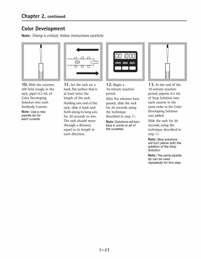
Color DevelopmentNote: Timing is critical; follow instructions carefully
10. With the cuvettes still held snugly in the rack, pipet 0.5 mL of Color Developing Solution into each Antibody Cuvette.Note: Use a new pipette tip for each cuvette.
11. Set the rack on a hard, flat surface that is at least twice the length of the rack. Holding one end of the rack, slide it back and forth along its long axis for 30 seconds to mix. The rack should move through a distance equal to its length in each direction.
12. Begin a 10-minute reaction period.After five minutes have passed, slide the rack for 20 seconds using the technique described in step 11.
Note: Solutions will turn blue in some or all of the cuvettes.
13. At the end of the 10-minute reaction period, pipette 0.5 mL of Stop Solution into each cuvette in the same order as the Color Developing Solution was added. Slide the rack for 20 seconds using the technique described in step 11.
Note: Blue solutions will turn yellow with the addition of the Stop Solution.
Note: The same pipette tip can be used repeatedly for this step.
HRS MIN SECHRS MIN SEC

1—24
Chapter 2, continued
Measuring the Color
14. Label and fill a Zeroing Cuvette with deionized water. Wipe the outside of all the cuvettes with a tissue to remove water, smudges, and fingerprints.
15. Press the POWER key to turn the meter on. The arrow can indicate either channel 1 or 2 for this method.Note: A user calibration should not be stored in the channel that you choose to use.
16. Insert the Zeroing Cuvette into the 1-cm micro-cuvette cell holder. Cover the zeroing cuvette with the instrument cap.Note: The arrow at the top of the cuvette should always face the key pad.
17. Press: ZERO/SCROLL. The instrument display will turn on and the display will show “---”, followed by “0.000”.
18. Remove the zeroing cuvette and insert the 0.5 ppb Atrazine calibrator into the cell holder. Cover the cuvette with the instrument cap.
19. Press: READ/ENTER. Record the absorbance value displayed.
20. Repeat step 18 and step 19 for the remaining calibrator.
21. Insert the first sample cuvette into the cell holder. Cover the cuvette with the instrument cap.
DIH O2
Repeat step 18 and step 19.
RepeatSteps 18–19

1—25
Chapter 2, continued
2.4 Interpreting the ResultsThere is an inverse relationship between the concentration of Atrazine and the absorbance. In other words, the higher the count value, the lower the concentration of Atrazine.
Example:
0.5 ppb Atrazine Calibrator: 0.450 Abs.
3.0 ppb Atrazine Calibrator: 0.230 Abs.
Sample #1: 0.150 Abs
Sample #2: 0.350 Abs
Sample #3: 0.550 Abs
Sample #1 — Sample absorbance is less than the absorbance for both calibrators. Therefore the sample concentration is greater than 0.5 and greater than 3.0 ppb Atrazine.
Sample #2 — Sample absorbance is between the absorbance for the 0.5 and 3.0 ppb Atrazine calibrators. Therefore the concentration of Atrazine is between 0.5 and 3.0 ppb Atrazine.
Sample #3 — Sample absorbance is greater than the absorbance for both calibrators. Therefore the sample concentration is less than 3.0 ppb and less than 0.5 ppb Atrazine.
22. Press: READ/ENTER. Record the absorbance value displayed.
23. Repeat step 21 and step 22 for all of the remaining samples.
Repeat step 21 and step 22.
RepeatSteps 21–22
If the sample absorbance is… Sample Atrazine Concentration is……less than calibrator absorbance …greater than the calibrator value
…greater than calibrator absorbance …less than the calibrator value

1—26
Chapter 2, continued
2.5 Storing and Handling Reagents• Wear protective gloves and eye wear.
• When storing reagent sets for extended periods of time,keep them out of direct sunlight. Reagent shelf life can be extended by refrigerating the reagents and is strongly recommended.
• Keep the foil pouch containing the Atrazine Antibody Cuvettes sealed when not in use.
• If Stop Solution comes in contact with eyes, wash thoroughly for 15 minutes with cold water and seek immediate medical help.
2.6 SensitivityThe Atrazine immunoassay test cannot differentiate between the various triazines and metabolites, but it detects their presence to differing degrees. The following table shows the required concentration for selected chemicals.
Compound Concentration Required to give a positive result at 3 ppb (in ppb)
Ametryne 1
Atrazine 3
Atrazine, de-ethylated 115
Atrazine, de-isopropyl 714
Cyanazine 460
Cyromazine 1200
Prometon 8
Prometryne 0.7
Propazine 2.3
Simetryne 5.4
Simazine 37
Terbuthylazine 91
Terbutryne 8.3
1—27
Chapter 2, continued
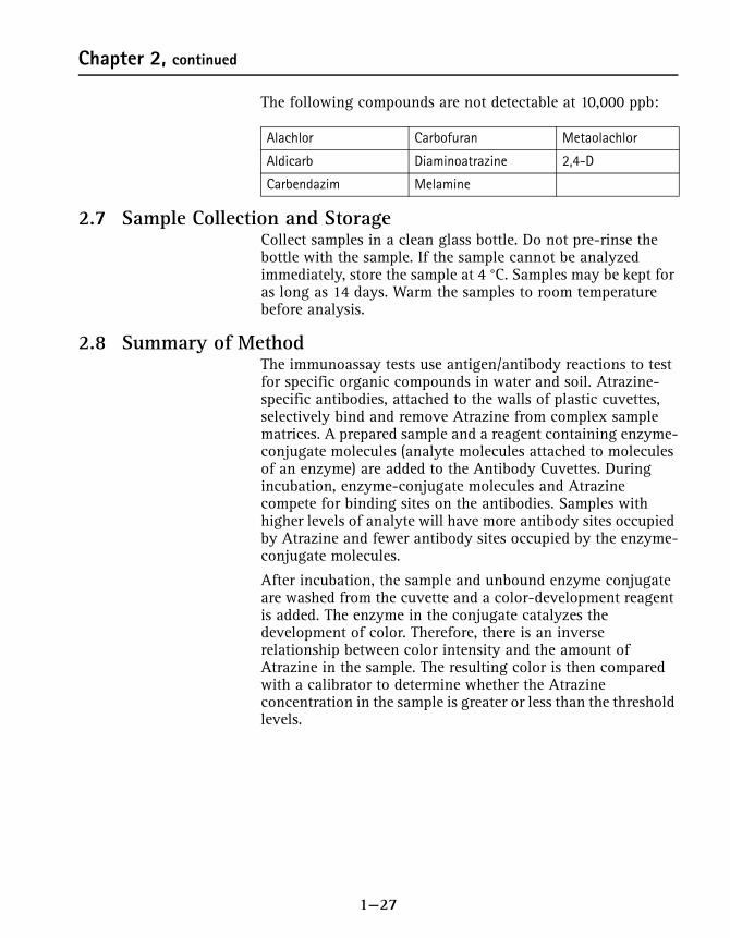
The following compounds are not detectable at 10,000 ppb:
2.7 Sample Collection and StorageCollect samples in a clean glass bottle. Do not pre-rinse the bottle with the sample. If the sample cannot be analyzed immediately, store the sample at 4 °C. Samples may be kept for as long as 14 days. Warm the samples to room temperature before analysis.
2.8 Summary of MethodThe immunoassay tests use antigen/antibody reactions to test for specific organic compounds in water and soil. Atrazine-specific antibodies, attached to the walls of plastic cuvettes, selectively bind and remove Atrazine from complex sample matrices. A prepared sample and a reagent containing enzyme-conjugate molecules (analyte molecules attached to molecules of an enzyme) are added to the Antibody Cuvettes. During incubation, enzyme-conjugate molecules and Atrazine compete for binding sites on the antibodies. Samples with higher levels of analyte will have more antibody sites occupied by Atrazine and fewer antibody sites occupied by the enzyme-conjugate molecules.
After incubation, the sample and unbound enzyme conjugate are washed from the cuvette and a color-development reagent is added. The enzyme in the conjugate catalyzes the development of color. Therefore, there is an inverse relationship between color intensity and the amount of Atrazine in the sample. The resulting color is then compared with a calibrator to determine whether the Atrazine concentration in the sample is greater or less than the threshold levels.
Alachlor Carbofuran Metaolachlor
Aldicarb Diaminoatrazine 2,4-D
Carbendazim Melamine
1—28
Chapter 2, continued
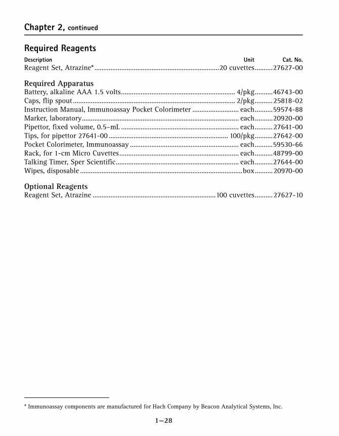
Required ReagentsDescription Unit Cat. No.Reagent Set, Atrazine* ......................................................................20 cuvettes..........27627-00
Required ApparatusBattery, alkaline AAA 1.5 volts................................................................ 4/pkg..........46743-00Caps, flip spout ........................................................................................... 2/pkg..........25818-02Instruction Manual, Immunoassay Pocket Colorimeter .......................... each..........59574-88Marker, laboratory........................................................................................ each..........20920-00Pipettor, fixed volume, 0.5–mL .................................................................. each..........27641-00Tips, for pipettor 27641-00 ................................................................... 100/pkg..........27642-00Pocket Colorimeter, Immunoassay ............................................................. each..........59530-66Rack, for 1-cm Micro Cuvettes................................................................... each..........48799-00Talking Timer, Sper Scientific..................................................................... each..........27644-00Wipes, disposable ...........................................................................................box..........20970-00
Optional ReagentsReagent Set, Atrazine .....................................................................100 cuvettes..........27627-10
* Immunoassay components are manufactured for Hach Company by Beacon Analytical Systems, Inc.

1—29
Chapter 3 Procedure for PCB in Soil
3.1 OverviewSoil samples are collected and PCB is extracted. Sample extracts, calibrators, and reagents are added to cuvettes coated with antibodies that are specific for PCB. Color develops and is then measured with a Pocket Colorimeter II. The test requires about 20 to 30 minutes for complete analysis. As many as 10 cuvettes can be run simultaneously.
The concentration of PCB in a sample is determined by comparing the developed color intensity to that of a PCB calibrator. The PCB concentration is inversely proportional to the color development: the lighter the color, the higher the PCB concentration. The Immunoassay Pocket Colorimeter provides a reading in terms of absorbance. This unit of measurement will allow you to compare your samples to the calibrators.
This method provides semi-quantitative screening based on thresholds for PCB in the following concentrations: 1 ppm, 5 ppm, 10 ppm and/or 50 ppm as Aroclor 1248.
3.2 Testing Hints1. Read the entire procedure before starting. Identify and
have ready all the necessary reagents, cuvettes, and other apparatus before beginning the analysis.
2. Timing is critical; follow instructions carefully.3. A consistent technique when mixing the cuvettes is
critical to this test. The best results come from using the cuvette rack and mixing as described in The 1-cm MicroCuvette Rack on page 2—3. Cuvettes can be mixed individually, but test results may not be as consistent.
4. Handle the cuvettes carefully. Scratches on the inside or outside may cause erroneous results. Clean the outside of the cuvettes with a clean absorbent cloth or tissue before placing them into the instrument. (Kimwipe® tissues are provided with the kit.)
5. Antibody cuvettes and enzyme conjugate are made in matched lots. Do not mix reagent lots.
6. Twenty Antibody Cuvettes are provided with each reagent set. One Antibody Cuvette will be used for each calibrator and each sample. Antibody Cuvettes are not reusable.
7. To avoid damaging the Color Developing Solution, do not expose it to direct sunlight.
1—30
Chapter 3, continued
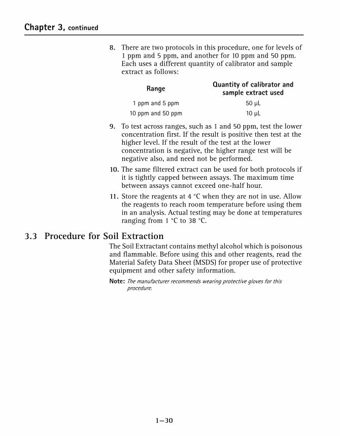
8. There are two protocols in this procedure, one for levels of 1 ppm and 5 ppm, and another for 10 ppm and 50 ppm. Each uses a different quantity of calibrator and sample extract as follows:
9. To test across ranges, such as 1 and 50 ppm, test the lower concentration first. If the result is positive then test at the higher level. If the result of the test at the lower concentration is negative, the higher range test will be negative also, and need not be performed.
10. The same filtered extract can be used for both protocols if it is tightly capped between assays. The maximum time between assays cannot exceed one-half hour.
11. Store the reagents at 4 °C when they are not in use. Allow the reagents to reach room temperature before using them in an analysis. Actual testing may be done at temperatures ranging from 1 °C to 38 °C.
3.3 Procedure for Soil ExtractionThe Soil Extractant contains methyl alcohol which is poisonous and flammable. Before using this and other reagents, read the Material Safety Data Sheet (MSDS) for proper use of protective equipment and other safety information.Note: The manufacturer recommends wearing protective gloves for this
procedure.
Range Quantity of calibrator and sample extract used
1 ppm and 5 ppm 50 µL
10 ppm and 50 ppm 10 µL
1—31
Chapter 3, continued
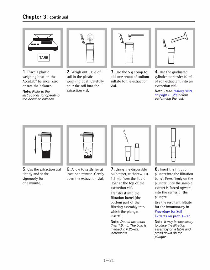
1. Place a plastic weighing boat on the AccuLab® balance. Zero or tare the balance.
Note: Refer to the instructions for operating the AccuLab balance.
2. Weigh out 5.0 g of soil in the plastic weighing boat. Carefully pour the soil into the extraction vial.
3. Use the 5 g scoop to add one scoop of sodium sulfate to the extraction vial.
4. Use the graduated cylinder to transfer 10 mL of soil extractant into an extraction vial.Note: Read Testing Hints on page 1—29, before performing the test.
5. Cap the extraction vial tightly and shake vigorously for one minute.
6. Allow to settle for at least one minute. Gently open the extraction vial.
7. Using the disposable bulb pipet, withdraw 1.0–1.5 mL from the liquid layer at the top of the extraction vial.Transfer it into the filtration barrel (the bottom part of the filtering assembly into which the plunger inserts).
Note: Do not use more than 1.5 mL. The bulb is marked in 0.25–mL increments
8. Insert the filtration plunger into the filtration barrel. Press firmly on the plunger until the sample extract is forced upward into the center of the plunger.Use the resultant filtrate for the immunoassy in Procedure for Soil Extracts on page 1—32.
Note: It may be necessary to place the filtration assembly on a table and press down on the plunger.
1—32
Chapter 3, continued
3.4 Procedure for Soil Extracts Note: Read Testing Hints on page 1—29 before proceeding.
Immunoassay
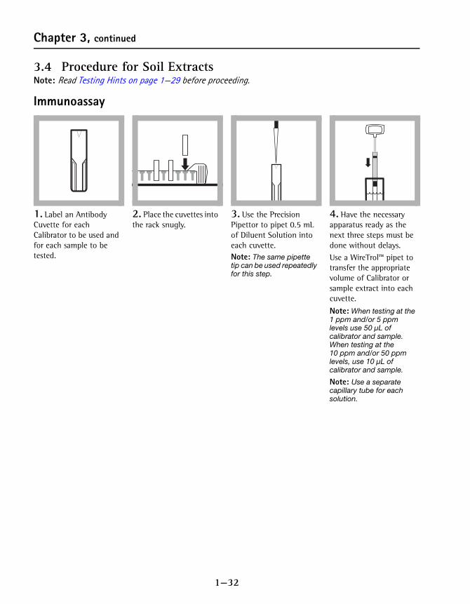
1. Label an Antibody Cuvette for each Calibrator to be used and for each sample to be tested.
2. Place the cuvettes into the rack snugly.
3. Use the Precision Pipettor to pipet 0.5 mL of Diluent Solution into each cuvette.Note: The same pipette tip can be used repeatedly for this step.
4. Have the necessary apparatus ready as the next three steps must be done without delays.Use a WireTrol™ pipet to transfer the appropriate volume of Calibrator or sample extract into each cuvette.
Note: When testing at the 1 ppm and/or 5 ppm levels use 50 µL of calibrator and sample. When testing at the 10 ppm and/or 50 ppm levels, use 10 µL of calibrator and sample.
Note: Use a separate capillary tube for each solution.
1—33
Chapter 3, continued
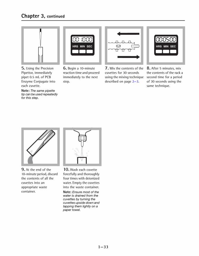
5. Using the Precision Pipettor, immediately pipet 0.5 mL of PCB Enzyme Conjugate into each cuvette.Note: The same pipette tip can be used repeatedly for this step.
6. Begin a 10-minute reaction time and proceed immediately to the next step.
7. Mix the contents of the cuvettes for 30 seconds using the mixing technique described on page 2—3.
8. After 5 minutes, mix the contents of the rack a second time for a period of 30 seconds using the same technique.
9. At the end of the 10-minute period, discard the contents of all the cuvettes into an appropriate waste container.
10. Wash each cuvette forcefully and thoroughly four times with deionized water. Empty the cuvettes into the waste container.Note: Ensure most of the water is drained from the cuvettes by turning the cuvettes upside down and tapping them lightly on a paper towel.
HRS MIN SECHRS MIN SEC HRS MIN SECHRS MIN SEC
1—34
Chapter 3, continued
Color DevelopmentNote: Timing is critical; follow instructions carefully.
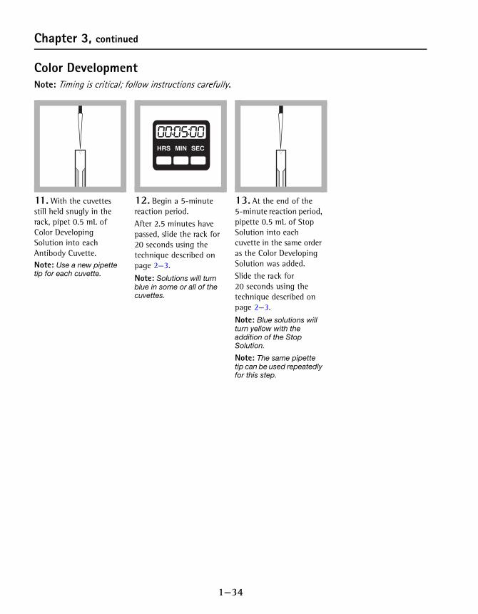
11. With the cuvettes still held snugly in the rack, pipet 0.5 mL of Color Developing Solution into each Antibody Cuvette.Note: Use a new pipette tip for each cuvette.
12. Begin a 5-minute reaction period.After 2.5 minutes have passed, slide the rack for 20 seconds using the technique described on page 2—3.
Note: Solutions will turn blue in some or all of the cuvettes.
13. At the end of the 5-minute reaction period, pipette 0.5 mL of Stop Solution into each cuvette in the same order as the Color Developing Solution was added. Slide the rack for 20 seconds using the technique described on page 2—3.
Note: Blue solutions will turn yellow with the addition of the Stop Solution.
Note: The same pipette tip can be used repeatedly for this step.
HRS MIN SECHRS MIN SEC

1—35
Chapter 3, continued
Measuring the Color
1. Label and fill a Zeroing Cuvette with deionized water. Wipe the outside of all the cuvettes with a tissue to remove water, smudges, and fingerprints.
2. Press the POWER key to turn the meter on. The arrow can indicate either channel 1 or 2 for this method.Note: A user calibration should not be stored in the channel that you choose to use.
3. Insert the Zeroing Cuvette into the 1-cm micro-cuvette cell holder. Cover the zeroing cuvette with the instrument cap.Note: The arrow at the top of the cuvette should always face forward.
4. Press: ZERO/SCROLL. The instrument display will turn on and the display will show “---”, followed by “0.000”.
5. Remove the zeroing cuvette and insert the first PCB calibrator into the cell holder. Cover the cuvette with the instrument cap.
6. Press: READ/ENTER. Record the absorbance value displayed. Hold the adapter in place when removing the cuvette.
7. Repeat step 5 and step 6 for all remaining calibrators, and samples.Record the absorbance value of each calibrator and sample. A Data Sheet (page 1—10) has been provided that may be photocopied and used for each set of tests.
DIH O2
RepeatSteps 18–19

1—36
Chapter 3, continued
3.5 Interpreting the ResultsThere is an inverse relationship between the concentration of PCB and absorbance. In other words, the higher the absorbance, the lower the concentration of PCB.
Example of Count Values
1 ppm PCB Calibrator: 0.450 Abs.
5 ppm PCB Calibrator: 0.230 Abs.
Sample #1: 0.150 Abs.
Sample #2: 0.350 Abs.
Sample #3: 0.550 Abs.
Interpretation
Sample #1 — Sample absorbance is less than the absorbance for both calibrators. Therefore the sample concentration is greater than 1 ppm and greater than 5 ppm as Aroclor 1248.
Sample #2 — Sample absorbance is between the absorbance for the 1 ppm and the 5 ppm PCB calibrators. Therefore the concentration of PCB is between 1 ppm and 5 ppm PCB as Aroclor 1248.
Sample #3 — Sample absorbance is greater than the absorbance for both calibrators. Therefore the sample concentration is less than 5 ppm and less than 1 ppm PCB as Aroclor 1248.
3.6 Storing and Handling Reagents• Wear protective gloves and eyewear.
• When storing reagent sets for extended periods of time, keep them out of direct sunlight. Store reagents at a temperature of 4 °C when not in use.
• Keep the foil pouch containing the PCB Antibody Cuvettes sealed when not in use.
• If Stop Solution comes in contact with eyes, wash thoroughly for 15 minutes with cold water and seek immediate medical help.
If the sample absorbance is… Sample PCB Concentration is……less than calibrator absorbance …greater than the calibrator value
…greater than calibrator absorbance …less than the calibrator value

1—37
Chapter 3, continued
3.7 SensitivityThe PCB immunoassay cannot differentiate between the various Aroclors, but it detects their presence in differing degrees.
The following compounds are not detectable at 1000 ppm.
3.8 Sample Collection and StorageAnalyze the samples as soon as possible after collection. If the samples must be stored, collect them in glass or Teflon® containers that have been washed with soap and water and rinsed with methanol. The container should be capped with a Teflon-lined cap. If a Teflon cap is not available, aluminum foil rinsed in methanol may be used as a substitute cap liner.
3.9 Summary of MethodHach immunoassay tests use antigen/antibody reactions to test for specific organic compounds in water and soil. PCB-specific antibodies, attached to the walls of plastic cuvettes, selectively bind and remove PCB from complex sample matrices. A prepared sample and a reagent containing enzyme-conjugate molecules (analyte molecules attached to molecules of an enzyme) are added to the Antibody Cuvettes. During incubation, enzyme-conjugate molecules and PCB compete for binding sites on the antibodies. Samples with higher levels of analyte will have more antibody sites occupied by PCB and fewer antibody sites occupied by the enzyme-conjugate molecules.
CompoundConcentration (ppm) to give a positive result at
1 ppm 5 ppm 10 ppm 50 ppm1248 1 5 10 50
1016 2 9 20 67
1242 1.2 6 14 50
1254 1.4 4.6 11 28
1260 1.1 4.9 11 38
Biphenyl 2,4,6-trichlorophenyl 1,3-dichlorobenzene
2,4-dicholorophenyl pentachlorophenol 1,4-dichlorobenzene
2,4,5-trichlorphenyl 1,2-dichlorobenzene 1,2,4-trichlorobenzene

1—38
Chapter 3, continued
After incubation, the sample and unbound enzyme conjugate are washed from the cuvette and a color-development reagent is added. The enzyme in the conjugate catalyzes the development of color. Therefore, there is an inverse relationship between color intensity and the amount of PCB in the sample. The resulting color is then compared with a calibrator to determine whether the PCB concentration in the sample is greater or less than the threshold levels.
Required ReagentsDescription Unit Cat. No.Reagent Set, PCB in Soil* .................................................................20 cuvettes..........27735-00
Required ApparatusBattery, alkaline AAA 1.5 volts................................................................ 4/pkg..........46743-00Caps, flip spout ........................................................................................... 2/pkg..........25818-02Instrument Manual, Immunoassay Pocket Colorimeter .......................... each..........59574-88Marker, laboratory........................................................................................ each..........20920-00Pipettor, fixed volume, 0.5–mL .................................................................. each..........27641-00Tips, for pipettor 27641-00 ................................................................... 100/pkg..........27642-00Pocket Colorimeter, Immunoassay ............................................................. each..........59530-66Rack, for 1-cm Micro Cuvettes................................................................... each..........48799-00Talking Timer, Sper Scientific..................................................................... each..........27644-00Wipes, disposable ...........................................................................................box..........20970-00For Soil Extraction only:Soil Extraction Kit........................................................................................ each..........27751-00
Includes:Balance, Acculab Pocket Pro 150B.........................................................each.......... 27969-00 Dropper, LDPE, 0.5 and 1.0-mL, ........................................................ 20/pkg.......... 21247-20Filter and Barrel Assembly.................................................................. 20/pkg.......... 25676-20Sodium Sulfate, anhydrous.................................................................... 250 g............ 7099-14Soil Extractant Solution......................................................................200 mL.......... 25677-29Soil Sample Container ......................................................................... 20/pkg.......... 25929-20Soil Scoop, 5 g, 4.25 cc ...........................................................................each.......... 26572-05Weighing Boat, 8.9 cm square............................................................. 20/pkg.......... 21790-20
Soil Extraction Refill Kit (resupplies the consumables for 27751-00) .. each..........27752-00
* Immunoassay components are manufactured for Hach Company by Beacon Analytical Systems, Inc.

1—39
Chapter 4 Procedure for TPH in Soil and Water
4.1 OverviewThis TPH test can be used for both soil and water testing. When testing soil, purchase the Soil Extraction Kit (see page 1—50) and perform the Procedure for Soil Extraction on page 1—40. When testing water samples only, proceed directly with the Immunoassay Procedure for Soil Extracts and Water Samples on page 1—42.
Soil samples or water samples are collected. If testing soils, first extract the TPH using the procedure in Chapter 4.3. Water samples or soil extracts, calibrators, and reagents are added to cuvettes that are coated with antibodies specific for TPH. Color develops and is then measured with a Hach Pocket Colorimeter. The test requires about 20 to 30 minutes for complete analysis. As many as 10 cuvettes can be run simultaneously.
The concentration of TPH in a sample is determined by comparing the developed color intensity to that of a TPH calibrator. The TPH concentration is inversely proportional to the color development: the lighter the color, the higher the TPH concentration. The Immunoassay Pocket Colorimeter provides a reading in terms of absorbance. This unit of measurement will allow you to compare your samples to the calibrators.
This method provides semi-quantitative screening based on thresholds for TPH as diesel fuel in the following concentrations:
Higher concentrations in water can be tested by first diluting the sample with deionized water (see Diluting Water Samples on page 1—48). Test for other TPH compounds (i.e., gasoline) by using the conversion factors given in Table 1 and Table 2 on page 1—48.
4.2 Tips and Techniques1. Read the entire procedure before starting. Identify and
have ready all the necessary reagents, cuvettes, and other apparatus before beginning the analysis.
2. Timing is critical; follow instructions carefully.3. A consistent technique when mixing the cuvettes is
critical to this test. The best results come from using the cuvette rack and mixing as described in The 1-cm
Soil 20, 50, 100, 200 ppm as diesel fuel
Water 2, 5, 10, 20 ppm as diesel fuel
1—40
Chapter 4, continued
MicroCuvette Rack on page 2—3. Cuvettes can be mixed individually, but test results may not be as consistent.
4. Handle the cuvettes carefully. Scratches on the inside or outside may cause erroneous results. Carefully clean the outside of the cuvettes with a clean absorbent cloth or tissue before placing them into the instrument. (Kimwipe® tissues are provided with the kit.)
5. Antibody cuvettes and enzyme conjugate are made in matched lots. Do not mix reagent lots.
6. Twenty Antibody Cuvettes are provided with each reagent set. One Antibody Cuvette will be used for each calibrator or sample. Antibody Cuvettes are not reusable.
7. To avoid damaging the Color Developing Solution, do not expose it to direct sunlight.
8. Store the reagents at 4 °C when they are not in use. Allow the reagents to reach room temperature before using them in an analysis. Actual testing may be done at temperatures ranging from 1 °C to 38 °C.
9. If the soil sample contains more than 20% moisture, it must be dried before analysis. Please contact Technical Support (see page 2—20) for further information about soil drying techniques.
4.3 Procedure for Soil ExtractionThe Soil Extractant contains methyl alcohol which is poisonous and flammable. Before using this and other reagents, read the Material Safety Data Sheet (MSDS) for proper use of protective equipment and other safety information.

1—41
Chapter 4, continued
Note: Hach Company recommends wearing protective gloves for this procedure.
1. Place a plastic weighing boat on the AccuLab® balance. Zero, or tare, the balance.
Note: Refer to the operating Instructions for AccuLab Balance.
2. Weigh out 10 g of soil in the plastic weighing boat. Carefully pour the soil into an extraction vial.
3. Use the 5 g scoop to add one scoop of sodium sulfate to the extraction vial.
4. Use the graduated cylinder to transfer 10 mL of Soil Extractant into the extraction vial.
5. Cap the extraction vial tightly and shake vigorously for one minute.
6. Allow to settle for at least one minute. Carefully open the extraction vial.
7. Using the disposable bulb pipet, withdraw 1.0–1.5 mL from the liquid layer at the top of the extraction vial.Transfer it into the filtration barrel (the bottom part of the filtering assembly into which the plunger inserts).
Note: Do not use more than 1.5 mL. The bulb is marked in 0.25–mL increments
8. Insert the filtration plunger into the filtration barrel. Press firmly on the plunger until the sample extract is forced upward into the center of the plunger. Use the resultant filtrate for the immunoassay in the Immunoassay Procedure for Soil Extracts and Water Samples on page 1—42.Note: You may need to place the filtration assembly on a table and press down on the plunger.

1—42
Chapter 4, continued
4.4 Immunoassay Procedure for Soil Extracts and Water Samples
Immunoassay
9. Label an Antibody Cuvette for each calibrator and each sample to be tested.To select the proper calibrators, see Table 1 on page 1—47.
Note: As many as 10 cuvettes may be tested at one time and may comprise any combination of samples and calibrators.
Note: See example below.
10. Place the cuvettes into the rack snugly.
11. Use the Precision Pipettor to pipet 0.5 mL of Diluent Solution into each Calibrator cuvette.Note: The same pipette tip can be used repeatedly for this step.
12. If testing soil: Pipet 0.5 mL of Diluent Solution into each sample cuvette.If testing water: Pipet 0.5 mL of each water sample into the appropriate cuvette.
Note: Use a new pipette tip for each water sample.
EXAMPLE
To test samples against the 50 ppm and 100 ppm diesel fuel calibrators, label one Antibody Cuvette “50” and a second cuvette “100.” Then label an Antibody Cuvette for each of up to eight samples to be tested. In this example, there is room for eight samples; samples plus calibrators cannot exceed 10. Using more calibrators will reduce the number of samples that can be run at the same time.

1—43
Chapter 4, continued
Note: Read Tips and Techniques on page 1—39 before proceeding.
13. Have the necessary apparatus at hand as the next three steps must be done without delays.Use a WireTrol™ pipet to transfer 50 µL of each calibrator to be used into the calibrator cuvettes.
Mix the cuvettes after each addition.
Note: Use a separate capillary tube for each solution.
14. If testing soil: Use a WireTrol pipet to transfer 50 µL of the filtered extract from step 8 into the appropriately labeled cuvette.Mix the cuvettes after the addition of each sample.
If testing water: Use a WireTrol pipet to transfer 50 µL of methanol into each sample cuvette
Note: Use a separate capillary tube for each solution.
15. Using the Precision Pipettor, immediately pipet 0.5 mL of TPH Enzyme Conjugate into each calibrator and sample cuvette.Note: The same pipette tip can be used repeatedly for this step.
16. Begin a 10-minute reaction time and proceed immediately to the next step.
17. Mix the contents of the cuvettes for 30 seconds using the technique described on page 2—3.
18. After 5 minutes, mix the contents of the rack a second time for a period of 30 seconds using the same technique.
19. At the end of the 10-minute period, discard the contents of all the cuvettes into an appropriate waste container.
20. Wash each cuvette forcefully and thoroughly four times with deionized water. Empty the rinse water into the waste container.Note: Ensure most of the water is drained from the cuvettes by turning the cuvettes upside down and tapping them lightly on a paper towel.
HRS MIN SECHRS MIN SEC
HRS MIN SECHRS MIN SEC

1—44
Chapter 4, continued
Color DevelopmentNote: Timing is critical; follow instructions carefully.
21. With the cuvettes still held snugly in the rack, pipet 0.5 mL of Color Developing Solution into each Antibody Cuvette.Note: Use a new pipette tip for each cuvette.
22. Begin a 10-minute reaction period and mix following the instructions on page 2—3.
23. After 5 minutes, mix the contents of the rack a second time for a period of 30 seconds using the same technique.Note: Solutions will turn blue in some or all of the cuvettes.
24. At the end of the 10-minute reaction period, pipette 0.5 mL of Stop Solution into each cuvette in the same order as the Color Developing Solution was added in step 21. Slide the rack for 20 seconds using the technique described on page 2—3.
Note: Blue solutions will turn yellow with the addition of the Stop Solution.
Note: The same pipette tip can be used repeatedly for this step.
HRS MIN SECHRS MIN SEC
HRS MIN SECHRS MIN SEC
1—45
Chapter 4, continued
Measuring the Color
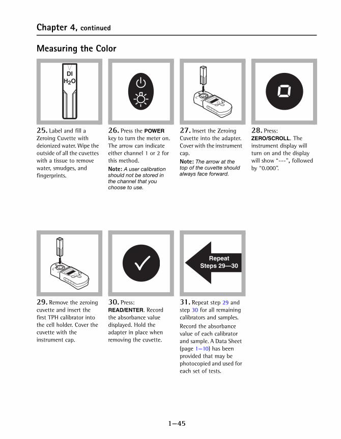
25. Label and fill a Zeroing Cuvette with deionized water. Wipe the outside of all the cuvettes with a tissue to remove water, smudges, and fingerprints.
26. Press the POWER key to turn the meter on. The arrow can indicate either channel 1 or 2 for this method.Note: A user calibration should not be stored in the channel that you choose to use.
27. Insert the Zeroing Cuvette into the adapter. Cover with the instrument cap.Note: The arrow at the top of the cuvette should always face forward.
28. Press: ZERO/SCROLL. The instrument display will turn on and the display will show “---”, followed by “0.000”.
29. Remove the zeroing cuvette and insert the first TPH calibrator into the cell holder. Cover the cuvette with the instrument cap.
30. Press: READ/ENTER. Record the absorbance value displayed. Hold the adapter in place when removing the cuvette.
31. Repeat step 29 and step 30 for all remaining calibrators and samples.Record the absorbance value of each calibrator and sample. A Data Sheet (page 1—10) has been provided that may be photocopied and used for each set of tests.
DIH O2
RepeatSteps 29—30

1—46
Chapter 4, continued
4.5 Interpreting the ResultsThere is an inverse relationship between the concentration of TPH and the absorbance value. In other words, the higher the absorbance value, the lower the concentration of TPH.
Example of Count Values
TPH Calibrator #1: 0.800 Abs.
TPH Calibrator #2: 0.600 Abs.
Sample #1: 0.150 Abs.
Sample #2: 0.700 Abs.
Sample #3: 0.950 Abs.
Interpretation
Interpretation for a soil sample:
Sample #1 — Sample absorbance is less than the absorbance for both calibrators. Therefore the sample concentration of TPH is greater than both 20 ppm and 50 ppm diesel fuel.
Sample #2 — Sample absorbance is between the absorbance for the TPH calibrators. Therefore the sample concentration of TPH is between 20 ppm and 50 ppm diesel fuel.
Sample #3 — Sample absorbance is greater than the absorbance for both calibrators. Therefore the sample concentration of TPH is less than both 20 ppm and 50 ppm diesel fuel.
Interpretation for a water sample*:
Sample #1 — Sample absorbance is less than the absorbance for both calibrators. Therefore the sample concentration of TPH is greater than both 2 ppm and 5 ppm diesel fuel.
Sample #2 — Sample absorbance is between the absorbance for the TPH calibrators. Therefore the sample concentration of TPH is between 2 ppm and 5 ppm diesel fuel.
Sample #3 — Sample absorbance is greater than the absorbance for both calibrators. Therefore the sample
If the sample absorbance is… the sample TPH Concentration is…
…less than calibrator absorbance …greater than the calibrator value
…greater than calibrator absorbance …less than the calibrator value
* See Diluting Water Samples on page 1—48 for instructions on how to correct for sample dilutions.
1—47
Chapter 4, continued
concentration of TPH is less than both 2 ppm and 5 ppm diesel fuel.
4.6 Storing and Handling Reagents• Wear protective gloves and eyewear.
• When storing reagent sets for extended periods of time, keep them out of direct sunlight. Store reagents at a temperature of 4 °C when not in use.
• Keep the foil pouch containing the TPH Antibody Cuvettes sealed when not in use.
• If Stop Solution comes in contact with eyes, wash thoroughly for 15 minutes with cold water and seek immediate medical help.
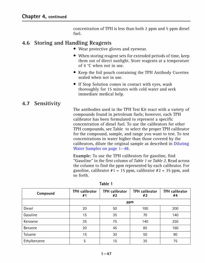
4.7 SensitivityThe antibodies used in the TPH Test Kit react with a variety of compounds found in petroleum fuels; however, each TPH calibrator has been formulated to represent a specific concentration of diesel fuel. To use the calibrators for other TPH compounds, see Table to select the proper TPH calibrator for the compound, sample, and range you want to test. To test concentrations in water higher than those covered by the calibrators, dilute the original sample as described in Diluting Water Samples on page 1—48.
Example: To use the TPH calibrators for gasoline, find “Gasoline” in the first column of Table 1 or Table 2. Read across the column to find the ppm represented by each calibrator. For gasoline, calibrator #1 = 15 ppm, calibrator #2 = 35 ppm, and so forth.
Table 1
Compound TPH calibrator #1
TPH calibrator #2
TPH calibrator #3
TPH calibrator #4
ppm
Diesel 20 50 100 200
Gasoline 15 35 70 140
Kerosene 35 75 140 250
Benzene 20 45 85 160
Toluene 15 30 50 90
Ethylbenzene 5 15 35 75

1—48
Chapter 4, continued
4.7.1 Diluting Water SamplesDilute the sample to 50 mL with deionized water in a graduated cylinder. (See Reagent Set, TPH 20 cuvettes 27743-00.)
Choose the mL of undiluted sample from Table 3. Use the multiplier value for the chosen quantity to multiply the value from Table 1 or Table 2, above.
m-Xylene 9 20 35 70
o-Xylene 10 20 40 80
p-Xylene 3 5 9 16
BTEX 5 15 25 45
Table 1 (Continued)
Compound TPH calibrator #1
TPH calibrator #2
TPH calibrator #3
TPH calibrator #4
ppm
Table 2
Compound TPH calibrator #1
TPH calibrator #2
TPH calibrator #3
TPH calibrator #4
ppm
Diesel 2 5 10 20
Gasoline 1.5 3.5 7 14
Kerosene 3.5 7.5 14 25
Benzene 2 4.5 8.5 16
Toluene 1.5 3 5 9
Ethylbenzene 0.5 1.5 3.5 7.5
m-Xylene 0.9 2 3.5 7
o-Xylene 1 2 4 8
p-Xylene 0.3 0.5 0.9 16
BTEX 0.5 1.5 2.5 4.5
Table 3
mL Sample Multiplier mL Sample Multiplier
0.5 100 5.0 10
1.0 50 10.0 5
2.0 25 25.0 2

1—49
Chapter 4, continued
For example: If a 0.5 mL water sample is diluted to 50 mL and tested, the calibrator levels for diesel fuel in water would represent 200, 500, 1000, and 2000 ppm respectively.
4.8 Sample Collection and StorageAnalyze the samples as soon as possible after collection. If the samples must be stored, collect them in glass or Teflon® containers that have been washed with soap and water and rinsed with methanol. The container should be capped with a Teflon-lined cap. If a Teflon cap is not available, aluminum foil rinsed in methanol may be used as a substitute cap liner.
When collecting water samples, fill the container completely (no head space) and cover the container with a tightly-sealed lid immediately after collection.
For Soil: Store the samples at 4 °C for no longer than 14 days.
For Water: Chill the sample in an ice bath or refrigerator to limit the loss of volatile compounds. Store samples no longer than 24 hours.
4.9 Summary of MethodHach immunoassay tests use antigen/antibody reactions to test for specific organic compounds in water and soil. Antibodies specific for TPH are attached to the walls of plastic cuvettes. They selectively bind and remove TPH from complex sample matrices. A prepared sample and a reagent containing enzyme-conjugate molecules (analyte molecules attached to molecules of an enzyme) are added to the Antibody Cuvettes. During incubation, enzyme-conjugate molecules and TPH compete for binding sites on the antibodies. Samples with higher levels of analyte will have more antibody sites occupied by TPH and fewer antibody sites occupied by the enzyme-conjugate molecules.
After incubation, the sample and unbound enzyme conjugate are washed from the cuvette and a color-development reagent is added. The enzyme in the conjugate catalyzes the development of color. Therefore, there is an inverse relationship between color intensity and the amount of TPH in the sample. The resulting color is then compared with a calibrator to determine whether the TPH concentration in the sample is greater or less than the threshold levels.

1—50
Chapter 4, continued
Required ReagentsDescription Unit Cat. No.Reagent Set, TPH * ............................................................................20 cuvettes..........27743-00Deionized water ....................................................................................... 500 mL.............. 272-48
Required ApparatusBattery, alkaline AAA, 1.5 volts............................................................... 4/pkg..........46743-00Caps, flip spout ........................................................................................... 2/pkg..........25818-02Instruction Manual, Immunoassay Pocket Colorimeter .......................... each..........59574-88Marker, laboratory........................................................................................ each..........20920-00Pipettor, fixed volume, 0.5-mL................................................................... each..........27641-00Tips, for pipettor 27641-00 ................................................................... 100/pkg..........27642-00Pocket Colorimeter™, Immunoassay .......................................................... each..........59530-66Rack, for 1-cm Micro Cuvettes................................................................... each..........48799-00Talking Timer, Sper Scientific..................................................................... each..........27644-00Wipes, disposable ...........................................................................................box..........20970-00
For Soil Extraction only:Soil Extraction Kit........................................................................................ each..........27751-00
Includes:Balance, Acculab Pocket Pro 150B.........................................................each.......... 27969-00 Dropper, LDPE, 0.5 and 1.0-mL, ........................................................ 20/pkg.......... 21247-20Filter and Barrel Assembly.................................................................. 20/pkg.......... 25676-20Sodium Sulfate, anhydrous.................................................................... 250 g............ 7099-14Soil Extractant Solution......................................................................200 mL.......... 25677-29Soil Sample Container ......................................................................... 20/pkg.......... 25929-20Soil Scoop, 5 g, 4.25 cc ...........................................................................each.......... 26572-05Weighing Boat, 8.9 cm square............................................................. 20/pkg.......... 21790-20
Soil Extraction Refill Kit (resupplies the consumables for 27751-00) ........................................... each..........27752-00
* Immunoassay components are manufactured for Hach Company by Beacon Analytical Systems, Inc.

2—1
Section 2 Instrument Manual

2—2

2—3
Accessories
The 1-cm MicroCuvette RackThis rack (see Figure 1) has been designed specifically to aid in achieving precise and accurate results when using the immunoassay technique to analyze several samples at the same time.
Figure 1 The 1-cm MicroCuvette Rack
Loading the Rack — The cuvette rack is designed so that it may be inverted with the cuvettes in place. Identify each cuvette with a sample or calibrator number and place all the cuvettes in the rack before beginning the procedure. Fit the cuvettes snugly into the rack, but do not force them or they may be difficult to remove and their contents may spill. The cuvettes should remain in place when the rack is inverted and tapped lightly.
Mixing — Set the rack on a hard, flat surface that is at least twice the length of the rack. Hold the rack by one end and vigorously slide it back and forth along its long axis for 30 seconds.
The rack should move through a distance equal to its own length in each direction.
2—4
Accessories, continued
Using the Precision Pipettor
Using the WireTrol™ Pipet
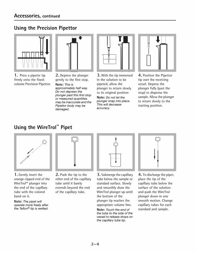
1. Press a pipette tip firmly onto the fixed-volume Precision Pipettor.
2. Depress the plunger gently to the first stop.Note: This is approximately half way. Do not depress the plunger past this first stop or measured quantities may be inaccurate and the Pipettor body may be damaged.
3. With the tip immersed in the solution to be pipeted, allow the plunger to return slowly to its original positionNote: Do not let the plunger snap into place. This will decrease accuracy.
4. Position the Pipettor tip over the receiving vessel. Depress the plunger fully (past the stop) to dispense the sample. Allow the plunger to return slowly to the starting position.
1. Gently insert the orange-tipped end of the WireTrol™ plunger into the end of the capillary tube with the colored band on it.
Note: The pipet will operate more freely after the Teflon® tip is wetted.
2. Push the tip to the other end of the capillary tube until it barely extends beyond the end of the capillary tube.
3. Submerge the capillary tube below the sample or standard surface. Slowly and smoothly draw the WireTrol plunger up until the bottom of the plunger tip reaches the appropriate volume line.Note: Touch the end of the tube to the side of the vessel to release drops on the capillary tube tip.
4. To discharge the pipet, place the tip of the capillary tube below the surface of the solution and push the WireTrol plunger down in one smooth motion. Change capillary tubes for each standard and sample.

2—5
Instrument Operation
Key Functions
Menu SelectionsPress the MENU key to access the menu selections.
Switching Ranges1. Press the MENU key. The display will show “SEL”. A flashing
arrow indicates the current range.
2. Press the READ/ENTER key to toggle between ranges. 3. Press menu again to accept and exit back to the
measurement screen.
Setting the Time1. Press the MENU key, then press the ZERO/SCROLL key until the
display shows a time in the “00:00” format.
2. Press READ/ENTER. The digit to be edited will flash. 3. Use the ZERO/SCROLL key to change the entry, then press
READ/ENTER to accept and advance to the next digit. The time is entered in 24-hour format.
Recalling Stored Measurements1. Press the MENU key, then press the ZERO/SCROLL key until the
display shows “RCL”. The instrument automatically stores the last 10 measurements.
Key Description Function
POWERKey
On/Off/Backlight To turn on backlight, turn on the instrument, then press and hold the power key until the backlight turns on. Press and hold again to turn off the backlight. This key functions the same in all instrument modes and ranges.
ZERO/SCROLLKey
In measurement mode, sets the instrument to zero. In menu mode, scrolls through menu options. Also scrolls numbers when entering or editing a value.
READ/ENTERkey
In measurement mode, initiates sample measurement. In menu mode, selects a menu option. When entering numbers, moves one space to the right and executes the function when the entry is complete.
MENUKey
Enter/Exit for the menu modePress and hold for about 5 seconds to enter user-entered method mode.

2—6
Instrument Operation, continued
2. In RCL mode, press READ/ENTER to recall the stored measurements, beginning with the most recent measurement taken. The meter stores the measurement number as 01 (most recent) through 10 (oldest), the time the measurement was taken, and the measurement value. The ZERO/SCROLL key allows for selection of a specific measurement by number. The READ/ENTER key scrolls through all stored data points.
Battery InstallationFigure 1 on provides an exploded view of battery installation.
1. Unhook the latch and remove the battery compartment cover. The polarities are shown on the battery holder.
2. Place the four batteries provided with the instrument in the holder as indicated and replace the battery compartment cover. The display will show the software version number (e.g., “P 1.6”) after correct battery installation.
When replacing discharged batteries, always replace the complete set of four alkaline batteries. Rechargeable batteries are not recommended and cannot be recharged in the instrument.Note: The Low Battery icon will appear on the display when the batteries
have 10% battery life remaining. The battery icon will flash when the batteries are too low to complete measurements. See Instrument Keys and Display on page 1—7.
Figure 1 Battery Installation
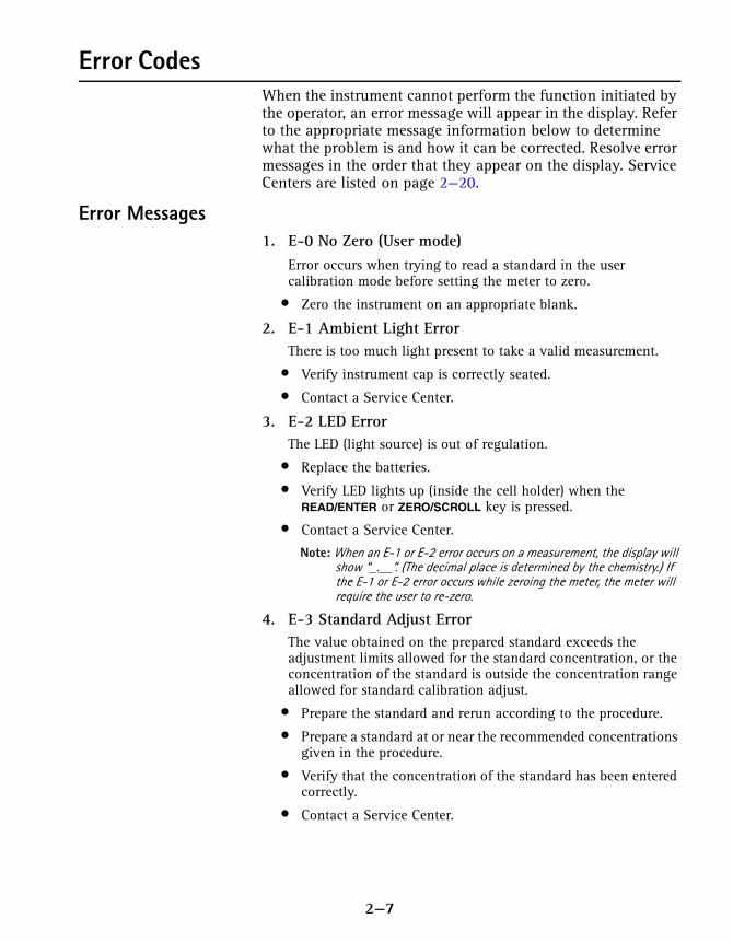
2—7
Error CodesWhen the instrument cannot perform the function initiated by the operator, an error message will appear in the display. Refer to the appropriate message information below to determine what the problem is and how it can be corrected. Resolve error messages in the order that they appear on the display. Service Centers are listed on page 2—20.
Error Messages1. E-0 No Zero (User mode)
Error occurs when trying to read a standard in the user calibration mode before setting the meter to zero.
• Zero the instrument on an appropriate blank.
2. E-1 Ambient Light ErrorThere is too much light present to take a valid measurement.
• Verify instrument cap is correctly seated.
• Contact a Service Center.
3. E-2 LED ErrorThe LED (light source) is out of regulation.
• Replace the batteries.
• Verify LED lights up (inside the cell holder) when the READ/ENTER or ZERO/SCROLL key is pressed.
• Contact a Service Center.
Note: When an E-1 or E-2 error occurs on a measurement, the display will show “_.__”. (The decimal place is determined by the chemistry.) If the E-1 or E-2 error occurs while zeroing the meter, the meter will require the user to re-zero.
4. E-3 Standard Adjust ErrorThe value obtained on the prepared standard exceeds the adjustment limits allowed for the standard concentration, or the concentration of the standard is outside the concentration range allowed for standard calibration adjust.
• Prepare the standard and rerun according to the procedure.
• Prepare a standard at or near the recommended concentrations given in the procedure.
• Verify that the concentration of the standard has been entered correctly.
• Contact a Service Center.

2—8
Error Codes, continued
5. E-6 Abs Error (User mode)Indicates that the absorbance value is invalid, or indicates an attempt to make a curve with less than two points.
• Enter or measure the absorbance value again.
• Contact a Service Center.
6. E-7 Standard Value Error (User mode)Standard concentration is equal to another standard concentration that is already entered.
• Enter the correct standard concentration.
• Contact a Service Center.
7. E-9 Flash ErrorThe meter is unable to save data.
• Contact a Service Center.
8. Underrange—flashing number below stated test range• Verify instrument cap is correctly seated.
• Check zero by measuring a blank. If error recurs, re-zero the instrument.
• Contact a Service Center.
Note: See Maximum/Minimum Displayed Value on page 2—16 for more information.
9. Overrange—flashing number above stated test rangeNote: Flashing value will be 10% over the upper test limit.
• Check for light blockage.
• Dilute and retest sample.
Note: See Maximum/Minimum Displayed Value on page 2—16 for more information.
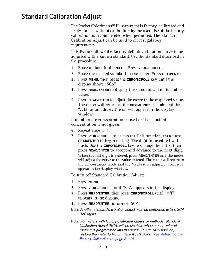
2—9
Standard Calibration AdjustThe Pocket Colorimeter™ II instrument is factory-calibrated and ready for use without calibration by the user. Use of the factory calibration is recommended when permitted. The Standard Calibration Adjust can be used to meet regulatory requirements.
This feature allows the factory default calibration curve to be adjusted with a known standard. Use the standard described in the procedure.
1. Place a blank in the meter. Press ZERO/SCROLL.2. Place the reacted standard in the meter. Press READ/ENTER.3. Press MENU, then press the ZERO/SCROLL key until the
display shows “SCA”. 4. Press READ/ENTER to display the standard calibration adjust
value.5. Press READ/ENTER to adjust the curve to the displayed value.
The meter will return to the measurement mode and the “calibration adjusted” icon will appear in the display window.
If an alternate concentration is used or if a standard concentration is not given:6. Repeat steps 1–4.7. Press ZERO/SCROLL to access the Edit function, then press
READ/ENTER to begin editing. The digit to be edited will flash. Use the ZERO/SCROLL key to change the entry, then press READ/ENTER to accept and advance to the next digit.When the last digit is entered, press READ/ENTER and the meter will adjust the curve to the value entered. The meter will return to the measurement mode and the “calibration adjusted” icon will appear in the display window.
To turn off Standard Calibration Adjust:
1. Press MENU. 2. Press ZERO/SCROLL until “SCA” appears in the display. 3. Press READ/ENTER, then press ZERO/SCROLL until “Off”
appears in the display. 4. Press READ/ENTER to turn off SCA.Note: Another standard calibration adjust must be performed to turn SCA
“on” again.
Note: For meters with factory-calibrated ranges or methods, Standard Calibration Adjust (SCA) will be disabled when a user-entered method is programmed into the meter. To turn SCA back on, restore the meter to factory default calibration. See Retrieving the Factory Calibration on page 2—16.

2—10
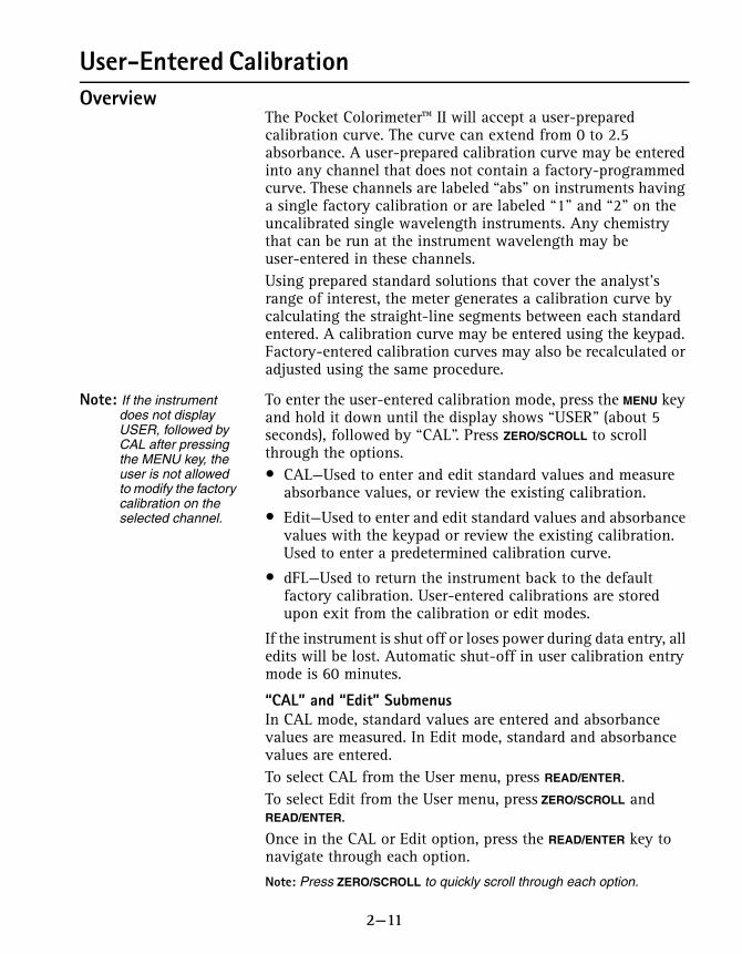
2—11
User-Entered Calibration Overview
The Pocket Colorimeter™ II will accept a user-prepared calibration curve. The curve can extend from 0 to 2.5 absorbance. A user-prepared calibration curve may be entered into any channel that does not contain a factory-programmed curve. These channels are labeled “abs” on instruments having a single factory calibration or are labeled “1” and “2” on the uncalibrated single wavelength instruments. Any chemistry that can be run at the instrument wavelength may be user-entered in these channels.Using prepared standard solutions that cover the analyst’s range of interest, the meter generates a calibration curve by calculating the straight-line segments between each standard entered. A calibration curve may be entered using the keypad. Factory-entered calibration curves may also be recalculated or adjusted using the same procedure.
Note: If the instrument does not display USER, followed by CAL after pressing the MENU key, the user is not allowed to modify the factory calibration on the selected channel.
To enter the user-entered calibration mode, press the MENU key and hold it down until the display shows “USER” (about 5 seconds), followed by “CAL”. Press ZERO/SCROLL to scroll through the options.• CAL—Used to enter and edit standard values and measure
absorbance values, or review the existing calibration.
• Edit—Used to enter and edit standard values and absorbance values with the keypad or review the existing calibration. Used to enter a predetermined calibration curve.
• dFL—Used to return the instrument back to the default factory calibration. User-entered calibrations are stored upon exit from the calibration or edit modes.
If the instrument is shut off or loses power during data entry, all edits will be lost. Automatic shut-off in user calibration entry mode is 60 minutes.
“CAL” and “Edit” SubmenusIn CAL mode, standard values are entered and absorbance values are measured. In Edit mode, standard and absorbance values are entered.To select CAL from the User menu, press READ/ENTER.To select Edit from the User menu, press ZERO/SCROLL and READ/ENTER. Once in the CAL or Edit option, press the READ/ENTER key to navigate through each option.
Note: Press ZERO/SCROLL to quickly scroll through each option.

2—12
User-Entered Calibration, continued
Calibration Procedure Using Prepared StandardsNote: Deionized water or a reagent blank can be used to zero during the
calibration procedure. Calibrations generated with deionized water as the zero will give less accurate results if the reagent blank is significantly more turbid or colored than deionized water. Use the deionized water or the reagent blank as the zero concentration point (S0) in the following calibration procedure.
Note: Deionized water or a reagent blank can be used to zero during the calibration procedure. Calibrations generated with deionized water as the zero will give less accurate results if the reagent blank is significantly different from deionized water. Use the deionized water or the reagent blank as the zero concentration point (S0) in the following calibration procedure.
1. Turn on the instrument and select the range to be calibrated. An arrow at the top of the display will point to the selected range. To change ranges, press the MENU key, then use the READ/ENTER key to toggle between ranges 1 and 2. Press MENU again to return to measurement mode.
2. Follow the procedure for the chemical method to be calibrated. Prepare a reagent blank (if needed) and a standard solution. Allow the color to develop fully.
3. Insert the reagent blank or deionized water into the meter and cover with the cap. Press the ZERO/SCROLL key. The meter will display “- - - -”, followed by “0.000”. This initializes (zeroes) the meter.
4. Press the MENU key and hold it down until the display shows “USER”, followed by “CAL”. Press READ/ENTER to enter the calibration mode.
5. In factory-calibrated meters, “S0” will appear in the display.Note: When recalibrating a factory-calibrated meter or range, RES
(resolution) cannot be changed.
6. In uncalibrated meters or meters with ranges labeled Abs, “RES” will appear. Press ZERO/SCROLL to review the current resolution. Press ZERO/SCROLL again to accept the current resolution. To change the resolution, press READ/ENTER, then ZERO/SCROLL to change the resolution (decimal placement). Press READ/ENTER to accept the new resolution. “S0” will appear on the display.
7. Press the READ/ENTER key again, then enter the blank value. Note: Press the READ/ENTER key to move from digit to digit. Use
the ZERO/SCROLL key to change the number.
8. After completing entry of the blank value, press the READ/ENTER key. The display will show “A0”.
9. Insert the reagent blank or deionized water into the cell holder. Cover the blank with the instrument cap.
10. Press the READ/ENTER key. The meter will measure and display the absorbance value for S0.

2—13
User-Entered Calibration, continued
11. Remove the sample blank. Press the ZERO/SCROLL key. “S1” will appear. Press the READ/ENTER key, then enter the first standard value. Note: Press the READ/ENTER key to move from digit to digit. Use
the ZERO/SCROLL key to change the number.
12. After completing entry of the first standard value, press the READ/ENTER key. The display will show “A1”.
13. Insert the first reacted standard solution into the cell holder. Cover the prepared standard with the instrument cap.
14. Press the READ/ENTER key. The meter will measure and display the absorbance value for S1.
15. The calibration is complete with two points. If additional standards are required, press ZERO/SCROLL until “Add” appears on the display. Repeat steps 11–14 to enter additional standards.
16. Press the MENU key twice to exit and accept the changes. The instrument will use this calibration to determine the displayed concentration of future sample measurements.
Entering a Predetermined Calibration CurveNote: Entering a predetermined calibration curve requires at least two
data pairs. Each data pair requires a concentration value and the absorbance value for the given concentration. Up to 10 data pairs may be entered. This procedure uses the Edit mode.
1. Turn on the instrument and select the range to be calibrated. An arrow at the top of the display will point to the selected range. To change ranges, press the MENU key, then use the READ/ENTER key to toggle between ranges 1 and 2. Press MENU again to return to measurement mode.
2. Press the MENU key and hold it down until the display shows “USER”, followed by “CAL”. Press ZERO/SCROLL to scroll to EDIT. Press READ/ENTER.
3. In uncalibrated meters or in Abs range, “RES” will appear. Press ZERO/SCROLL. To change the resolution (decimal placement), press READ/ENTER. Press ZERO/SCROLL to select the new resolution, then press READ/ENTER the accept. “S0” will appear on the display.
4. Enter the concentration value and absorbance value of the first data pair (S0, A0).
5. To enter the S0 value, press the READ/ENTER. Use the ZERO/SCROLL key to select the numerical value, then press

2—14
User-Entered Calibration, continued
the READ/ENTER key to accept the entry and advance to the next decimal place. Repeat this sequence until the S0 concentration value is entered.
6. After editing the S0 value, press READ/ENTER to accept. “A0” will appear on the display.
7. To enter the absorbance value for A0, press the READ/ENTER key to go to entry mode. Use the ZERO/SCROLL key to select the numerical value, then press the READ/ENTER key to accept the entry and advance to the next decimal place. Repeat this sequence until the absorbance value for A0 is entered.
8. After entering A0, press READ/ENTER to accept. “S1” will appear on the display.
9. Repeat steps 5 through 8 for each standard value and absorbance value pair in the calibration curveNote: After A1 is entered, “Add” will appear in the display. If
additional data pairs are to be entered, press READ/ENTER and continue with step 9.
10. When all the calibration data has been entered, press MENU twice to return to the measurement mode.
Editing a User-entered or Factory Calibration CurveNote: If the instrument
does not display USER, followed by CAL after pressing the MENU key, the user is not allowed to modify the factory calibration on the selected channel.
1. Press the MENU key and hold it down until the display shows “USER”, followed by “CAL”. Press ZERO/SCROLL until EDIT appears.
2. Press the READ/ENTER key to enter Edit mode. In factory-calibrated meters, “S0” will appear in the display.Note: When editing a factory-calibrated meter or range, RES
(resolution) cannot be changed.
Note: When RES or S0 appears in the display, press ZERO/SCROLL to quickly scroll the data to be edited.
3. In uncalibrated meters or in Abs range, “RES” will appear. Press ZERO/SCROLL to review the current resolution. Press ZERO/SCROLL again to accept the displayed resolution. To change the resolution, press READ/ENTER. Press ZERO/SCROLL to select the new resolution, then press READ/ENTER the accept. S0 will appear on the display.
4. Press READ/ENTER. The current concentration value for S0 will appear on the display.
5. To edit the S0 value, press the READ/ENTER. Use the ZERO/SCROLL key to select the numerical value, then press the READ/ENTER key to accept the entry and advance to the

2—15
User-Entered Calibration, continued
next decimal place. Repeat this sequence until the S0 concentration value is entered.
6. After editing the S0 value, press READ/ENTER to accept. “A0” will appear on the display.
7. To edit the absorbance value for A0, press the READ/ENTER key to go to entry mode. Use the ZERO/SCROLL key to select the numerical value, then press the READ/ENTER key to accept the entry and advance to the next decimal place. Repeat this sequence until the absorbance value for A0 is entered.
8. After editing A0, press READ/ENTER to accept. “S1” will appear on the display.
9. Repeat steps 4 through 8 for each standard value and absorbance value pair in the calibration curve.
10. When all calibration data has been reviewed or edited, Add will appear in the display.
11. Press READ/ENTER to add more calibration points, or press MENU twice to return to the measurement mode. Note: When a factory calibration curve has been edited, the
“calibration adjust” icon will appear in the display.
Exiting the Calibration RoutineExit the calibration routine by pressing the MENU key to step back through to measurement mode. The instrument uses the last completed user-entered calibration or the factory calibration if no user-entered calibration has been completed.
Deleting Calibration Points1. Select the range containing user-entered calibration points.
See Switching Ranges on page 2—5.2. Press and hold the MENU key until “USER”, then “CAL”
appears. Press READ/ENTER.Note: Calibration points can also be deleted in Edit mode.
3. Press ZERO/SCROLL to select the point to delete (e.g., S0 or S1 or S2). Press READ/ENTER.
4. The left digit will flash. Press ZERO/SCROLL until “dEL” appears. (“dEL” will appear after the numeral 9.)
5. Press READ/ENTER to delete. Repeat for all points to be deleted.
Note: The minimum number of valid points is two. For example, if five points have been entered, three can be deleted using this feature.

2—16
User-Entered Calibration, continued
6. Press MENU to return to the measurement mode.
Retrieving the Factory CalibrationNote: If the instrument
does not display USER, followed by CAL after pressing the MENU key, the user is not allowed to modify the factory calibration on the selected channel. The factory default calibration cannot be retrieved.
1. Select the range to restore factory default calibration. See Switching Ranges on page 2—5.
2. Press and hold the MENU key until “User”, then “CAL” appears.
3. Press the ZERO/SCROLL key to find dFL. 4. Press the READ/ENTER key to select dFL and restore the
instrument to the factory default calibration.Note: For meters with factory-calibrated ranges or methods,
Standard Calibration Adjust (SCA) will be disabled when a user-entered method is programmed into the meter. To turn SCA back on, restore the meter to factory default calibration.
Maximum/Minimum Displayed ValueIn meters with absorbance (Abs) ranges, the maximum displayed value and minimum displayed value is related to the value of the standards entered in a user calibration. Measurements that exceed the minimum or maximum standards entered in the user calibration will return a flashing number indicating “underrange” or “overrange”. See Error Messages on page 2—7 for more information. Example 1 For a calibration with the following standards:S0=0.000S1=1.000
Example 2For a calibration with the following standards:S0=1.00S1=2.00S2=4.00
For factory-calibrated programs, the maximum and minimum displayed values always equal the factory-calibrated values, and cannot be changed.
Maximum Displayed Value 1.000Minimum Displayed Value 0.000
Maximum Displayed Value 4.00Minimum Displayed Value 1.00

2—17
CertificationHach Company certifies this instrument was tested thoroughly, inspected, and found to meet its published specifications when it was shipped from the factory.
The Pocket Colorimeter™ II instrument has been tested and is certified as indicated to the following instrumentation standards:
EMC Immunity:Per 89/ 336/ EEC EMC: EN 61326: 1998 (Electrical Equipment for measurement, control and laboratory use—EMC requirements). Supporting test records by Hach Company, certified compliance by Hach Company.
Standard(s) include:
IEC 1000-4-2: 1995 (EN 61000-4-2: 1995) Electrostatic Discharge Immunit (Criteria B)
IEC 1000- 4- 3: 1995 (EN 61000- 4- 3: 1996) Radiated RF Electromagnetic Field Immunity (Criteria A)
Additional Immunity Standard( s) include:
ENV 50204: 1996 Radiated Electromagnetic Field from Digital Telephones (Criteria A) Radio Frequency Emissions:
Per 89/ 336/ EEC EMC: EN 61326: 1998 (Electrical Equipment for measurement, control and laboratory use—EMC requirements) “Class B” emission limits. Supporting test records from Hach EMC Test Facility, certified compliance by Hach Company.
Additional Radio Frequency Emissions Standard(s) include:EN 55022 (CISPR 22), Class B emissions limits.
Canadian Interference-causing Equipment Regulation, IECS-003, Class A: Supporting test records from Hach EMC Test Facility, certified compliance by Hach Company.
This Class A digital apparatus meets all requirements of the Canadian Interference-Causing Equipment Regulations.
Cet appareil numérique de la classe A respecte toutes les exigences du Règlement sur le matériel brouilleur du Canada.
FCC Part 15, Class “A” Limits: Supporting test records from Hach EMC Test Facility, certified compliance by Hach Company.
This device complies with Part 15 of the FCC Rules. Operation is subject to the following two conditions:

2—18
Certification, continued
(1) This device may not cause harmful interference, and (2) This device must accept any interference received, including interference that may cause undesired operation Changes or modifications to this unit not expressly approved by the party responsible for compliance could void the user's authority to operate the equipment.
This equipment has been tested and found to comply with the limits for a Class A digital device, pursuant to Part 15 of the FCC Rules. These limits are designed to provide reasonable protection against harmful interference when the equipment is operated in a commercial environment. This equipment generates, uses, and can radiate radio frequency energy and, if not installed and used in accordance with the instruction manual, may cause harmful interference to radio communications. Operation of this equipment in a residential area is likely to cause harmful interference, in which case the user will be required to correct the interference at his own expense. The following techniques of reducing the interference problems are applied easily
1. Remove power from the Pocket Colorimeter II instrument by removing one of its batteries to verify that it is or is not the source of the interference.
2. Move the Pocket Colorimeter II instrument away from the device receiving the interference.
3. Reposition the receiving antenna for the device receiving the interference.
4. Try combinations of the above.

2—19
At Hach Company, customer service is an important part of every product we make.
With that in mind, we have compiled the following information for your convenience.
General Information

2—20
How To Order
Information Required
Technical and Customer Service (U.S.A. only)Hach Technical and Customer Service Department personnel are eager to answer questions about our products and their use. Specialists in analytical methods, they are happy to put their talents to work for you.Call 1-800-227-4224 or E-mail [email protected].
International CustomersHach maintains a worldwide network of dealers and distributors. To locate the representative nearest you, send E-mail to intl@hach. com or contact:
In Canada, Latin America, Africa, Asia, Pacific Rim:Telephone: (970) 669-3050; FAX: (970) 669-2932
In Europe, the Middle East, or Mediterranean Africa:HACH Company, c/oDr. Bruno Lange GmbHWillstätterstr. 11D-40549 DüsseldorfGermanyTelephone: +49/[0]211.52.88.0Fax: +49/[0]211.52.88.231
By Telephone: By Mail:6:30 a.m. to 5:00 p.m. MSTMonday through Friday(800) 227-HACH(800-227-4224)By FAX: (970) 669-2932
Hach CompanyP.O. Box 389Loveland, CO 80539-0389U.S.A.
Ordering information by E-mail: [email protected]
• Hach account number (if available) • Billing address
• Your name and phone number • Shipping address
• Purchase order number • Catalog number
• Brief description or model number • Quantity
2—21
Repair ServiceAuthorization must be obtained from Hach Company before sending any items for repair. Please contact the HACH Service Center serving your location.
In the United States:Hach Company100 Dayton AvenueAmes, Iowa 50010(800) 227-4224 (U.S.A. only)Telephone: (515) 232-2533FAX: (515) 232-1276
In Canada:Hach Sales & Service Canada Ltd.1313 Border Street, Unit 34Winnipeg, ManitobaR3H 0X4(800) 665-7635 (Canada only)Telephone: (204) 632-5598FAX: (204) 694-5134E-mail: [email protected]
In Latin America, the Caribbean, the Far East, theIndian Subcontinent, Africa, Europe, or the Middle East:Hach Company World HeadquartersP.O. Box 389Loveland, Colorado, 80539-0389U.S.A.Telephone: (970) 669-3050FAX: (970) 669-2932E-mail: [email protected]

2—22
WarrantyHach Company warrants this product to the original purchaser against any defects that are due to faulty material or workmanship for a period of one year from date of shipment.
In the event that a defect is discovered during the warranty period, Hach Company agrees that, at its option, it will repair or replace the defective product or refund the purchase price, excluding original shipping and handling charges. Any product repaired or replaced under this warranty will be warranted only for the remainder of the original product warranty period.
This warranty does not apply to consumable products such as chemical reagents; or consumable components of a product, such as, but not limited to, lamps and tubing.
Contact Hach Company or your distributor to initiate warranty support. Products may not be returned without authorization from Hach Company.
LimitationsThis warranty does not cover:
• damage caused by acts of God, natural disaster, labor unrest, acts of war (declared or undeclared), terrorism, civil strife or acts of any governmental jurisdiction
• damage caused by misuse, neglect, accident or improper application or installation
• damage caused by any repair or attempted repair not authorized by Hach Company
• any product not used in accordance with the instructions furnished by Hach Company
• freight charges to return merchandise to Hach Company
• freight charges on expedited or express shipment of warranted parts or product
• travel fees associated with on-site warranty repairThis warranty contains the sole express warranty made by Hach Company in connection with its products. All implied warranties, including without limitation, the warranties of merchantability and fitness for a particular purpose, are expressly disclaimed.
Some states within the United States do not allow the disclaimer of implied warranties and if this is true in your state the above limitation may not apply to you. This warranty gives you specific rights, and you may also have other rights that vary from state to state.
This warranty constitutes the final, complete, and exclusive statement of warranty terms and no person is authorized to make any other warranties or representations on behalf of Hach Company.
Limitation of RemediesThe remedies of repair, replacement or refund of purchase price as stated above are the exclusive remedies for the breach of this warranty. On the basis of strict liability or under any other legal theory, in no event shall Hach Company be liable for any incidental or consequential damages of any kind for breach of warranty or negligence.