pH/mV/Rel mV/°C Benchtop Meters pH/mV/Ion/°C C meter with RS-232 and Recorder output 9 6...
58
pH/mV/°C meter with RS-232 and Recorder output 9 6 ± 8 5 2 0 7 4 1 • ON/OFF SHIFT YES NO CAL MEAS MODE HOLD SETUP REL MV BASE SET TEMP OFFSET SLOPE RESLN ACTIVATE SET TIMER ALARM READY CAL EDIT BEEP MR OPTIONS MI OPTIONS PRINT OPTIONS 3 pH/mV/Rel mV/° C Benchtop Meters and pH/mV/Ion/° C Benchtop Meters 35616-00 35616-03 35616-05 35616-08 35616-01 35616-02 35616-06 35616-07 35620-10 35620-13 35620-15 35620-18 35620-11 35620-12 35620-16 35620-17 1200 ©2000 70149 Model numbers:
Transcript of pH/mV/Rel mV/°C Benchtop Meters pH/mV/Ion/°C C meter with RS-232 and Recorder output 9 6...

pH/mV/°C meter
with RS-232 and Recorder output
9
6
±
8
5
2
0
7
4
1
•
ON/OFF
SHIFT
YES
NO
CALMEAS
MODE
HOLD
SETUPREL MVBASE
SET TEMPOFFSET
SLOPE
RESLN
ACTIVATESETTIMER
ALARMREADY
CAL EDITBEEP
MROPTIONS
MIOPTIONS
PRINTOPTIONS
3
pH/mV/Rel mV/° C Benchtop Metersand
pH/mV/Ion/° C Benchtop Meters
35616-0035616-0335616-0535616-08
35616-0135616-0235616-0635616-07
35620-1035620-1335620-1535620-18
35620-1135620-1235620-1635620-17
1200 ©200070149
Model numbers:

2

Table of contents1. Introduction ...............................................................................................................................................................................42. Keypad functions ................................................................................................................................................................5–8
• Primary keys • Secondary keys • Numeric keys
3. Starting up the meter......................................................................................................................................................9–10• Back panel connections • Turning the meter on and off
4. pH calibration......................................................................................................................................................................11–12• 1-point calibration • 2-point calibration (up to 5-point)
5. Relative mV calibration..........................................................................................................................................................136. Ion calibration...........................................................................................................................................................................147. Measurement: Ready, continuous, hold......................................................................................................................15-168. Measuring pH ...........................................................................................................................................................................179. Measuring mV...........................................................................................................................................................................17
10. Measuring Relative mV ..........................................................................................................................................................1811. Measuring Ion Concentration ..............................................................................................................................................1912. Automatic temperature compensation (ATC) and manual temperature compensation..................................2013. Setup functions and setup keys..................................................................................................................................21-25
• General • Setup functions at a glance • Program 1: viewing previous pH calibration data • Program 2: selecting meter operations (Reset and Auto-off) • Program 3: setting clock functions • Program 4: Selecting communication (RS-232) data
14. Switching the pH resolution ...............................................................................................................................................2615. Setting the READY indicator ..............................................................................................................................................2716. Setting the audible beep......................................................................................................................................................2817. Checking offset.......................................................................................................................................................................2918. Checking slope.........................................................................................................................................................................2919. Setting the high and low pH setpoint alarm.................................................................................................................3020. Setting and activating the timer........................................................................................................................................3121. Memory input functions and options .......................................................................................................................32-3322. Memory recall functions and options..............................................................................................................................3423. Setting up the optional printer and RS-232 output.............................................................................................35-51
• Using the meter with a printer • Connecting the cable to the meter • Connecting the cable to the printer • Using the meter with a printer to download stored memory • Print function and options • Using the meter with a computer and the Datalog Assist Software (DAS)• Loading the Data Acquisition Software • DAS main menu options • DAS data file management (continuous logging; downloading meter memory) • DAS functions • Exiting DAS
24. pH electrode care and maintenance.........................................52-5325. Error messages.....................................................................................5426. Troubleshooting guide .........................................................................5427. pH buffer/temperature table .............................................................5528. Specifications ......................................5629. Accessories ...........................................5730. Warranty ...............................................5831. Return of items ...................................58
warranty/return items
specifications/accessories
pH buffertemperature
tables
trouble shooting/error
messages
electrode care and
maintenance
printing/RS-232
memoryinput/recall
alarm/timer
resolution/READY/offset/
slope
setupfunctions
temperature
measurement
calibration
starting up
keypad functions
introduction
3
Quick tip let the mini table of contents in the outermargins of this manual guide you instantlyto the right section!

warranty/return items
specifications/accessories
pH buffertemperature
tables
trouble shooting/error
messages
electrode care and
maintenance
printing/RS-232
memoryinput/recall
alarm/timer
resolution/READY/offset/
slope
setupfunctions
temperature
measurement
calibration
starting up
keypad functions
introduction
4
pH/mV/°C meter
with RS-232 and Recorder output
9
6
±
8
5
2
0
7
4
1
•
ON/OFF
SHIFT
YES
NO
CALMEAS
MODE
HOLD
SETUPREL MVBASE
SET TEMPOFFSET
SLOPE
RESLN
ACTIVATESETTIMER
ALARMREADY
CAL EDITBEEP
MROPTIONS
MIOPTIONS
PRINTOPTIONS
3
1. IntroductionThank you for selecting the OAKTON® pH/mV°C meter orOAKTON pH/mV/Ion/°C meter. This manual providesinstructions for the 35616- and 35620-series meters.Each section includes illustrations that show you which but-ton to press for each major function.
Getting started (sections 2 through 12)To perform the basic functions of this meter, read sections 2 through 12 of this manual. These sections include basicinstructions (about keypad functions, connecting the electrodes, calibration, measuring, etc.) that will get you up and running quickly. These sections are indicated in theouter margins as Starting Up, Calibration, Measurement, andTemperature.
Advanced functions (sections 13 through 22)To perform the advanced functions of this meter, read sections 13 through 22 of this manual. Advanced functionsinclude the setup programs (“Auto-Off”, setting the timeand date, memory clear and reset, selecting RS-232 parameters, etc.), setting the high and low point alarms,memory input and recall, and other special features that will let you fine tune the efficiency of your meter. These sections are indicated in the outer margins as SetupFunctions, Offset/Slope, Alarm/Timer, and MemoryInput/Recall.
RS-232/printer output (section 23)To setup the parameters for RS-232 and printer output, read section 23 of this manual. This section applies only to meters with RS-232/printer capability.
Maintenance, troubleshooting, etc. (sections 24 through 31)The remaining sections of the manual deal with electrodemaintenance, error messages, and troubleshooting. This part of the manual also includes specifications, accessories,warranty, and return of items.

keypad functions
warranty/return items
specifications/accessories
pH buffertemperature
tables
trouble shooting/error
messages
electrode care and
maintenance
printing/RS-232
memoryinput/recall
alarm/timer
resolution/READY/offset/
slope
setupfunctions
temperature
measurement
calibration
starting up
introduction
5
9
6
3
±
8
5
2
0
7
4
1
•
ACTIVATESET
TIMER
SET TEMPOFFSET
SETUPREL MVBASE
PRINTOPTIONS
MROPTIONS
ALARMREADY
SLOPERESLN
MODE HOLD
CAL EDITBEEPYESON/OFF
SHIFT NO MIOPTIONS
CALMEAS
A
B
To perform secondary functions:A. press SHIFT key to access
secondary functionB. press specific key for that function
(example: the SET TEMP/OFFSET button's secondary function is to display the offset of the pH electrode)
Figure 1 above shows primary display(here displaying pH) and secondary display (shows temperature).
2. Keypad functionsThe large membrane keypad makes the instrument easy touse. Each button, when pressed, has a correspondinggraphic indicator on the display. While in the measurementfunction, the primary display shows the readings for pH, rel-ative mV, mV and Ion Concentration. The secondary displayshows the temperature readings simultaneously with theprimary display (Figure 1)
NOTE: The secondary display shows “Ion”(not tempera-ture) in Ion concentration mode.
The meter also has primary and secondary functions. To perform primary functions, press the appropriate func-tion key. During operation, the meter assumes the primaryfunctions are active.To perform secondary functions, press SHIFT first, andthen the appropriate function key.
ON/OFFPrimary function: Powers the meter on or off. The meteralways starts-up in the pH measure (MEAS) mode. Whenthe meter is OFF, the display shows current time wheneverthe AC adapter is plugged in.Secondary function: None.Numeric value: None.
SHIFTPrimary function: Press to perform secondary functions.Secondary function: None.Numeric value: None.
CAL/MEASPrimary function: Press to toggle between the calibrationmodes and measure functions. Also, exit from the setupmode and secondary functions.Secondary function: None.Numeric value: None.
MEASpH
°C
pH
Numeric key valuesSome keys also have numeric values. Donot press SHIFT to enter numeric values.The instrument knows when to enter a numeric value (for calibration, setting temperature, etc.). and when to activate a primary or secondary function.

YESPrimary function: Enter numeric values, con-firm calibration points, or confirm and scroll theprogram options in setup mode.Secondary function: None.Numeric value: None.
NOPrimary value: Use to cancel an incorrectlyselected numeric value. Secondary function: None.Numeric value: None.
MODEPrimary value: Selects the four measurement modes: pH, mV, relative mV, and Ion Concentration.Secondary function: None.Numeric value: 1.
HOLD Primary value: Freezes the displayed value and displays the HOLD annunciator. Press the key againto release display. HOLD is active only in Measurement mode. While in Hold mode, you can pressPRINT to print, or MI to store values.Secondary function: None.Numeric value: 2.
SETUP/REL MV BASE Primary function: Lets you enter Setup mode. Lets you customize most the functions of the instru-ment. Setup mode options are described in section 13, page 21-25. NOTE: select CAL/MEAS anytime to exit from the setup mode.Secondary function: Displays the rel mV base for two seconds, then meter automatically resumesnormal operation. Value displays in primary field of LCD. To change the rel mV base, enter the rel mVmode and press CAL: see page 13 for full instructions. Press SHIFT + MV BASE.Numeric value: 3.
/RESLN Primary function: Selects the next higher buffer in pH calibration mode. Also use to scroll throughsetup mode options.Secondary function: Switch resolution of measured pH. Automatically toggles from 0.01 to 0.1, or0.1 to 0.01. Press SHIFT + RESLN.
NOTE: In the mV, relative mV, and Ion concentration modes, the meter automatically displays thehighest resolution possible up to 31⁄2 digits.
Numeric value: 4.
/SLOPEPrimary function: Selects the next lower buffer in the pH calibration mode. Also use to scrollthrough setup mode options.Secondary: Displays percentage slope of the pH electrode (pH mode), or slope in mV per tenfoldincrease of ion concentration (Ion mode). Percentage slope is calculated as the average of the seg-ments between the calibrated points. Value displays for two seconds before the meter reverts to its normal display. Press SHIFT + SLOPE.
Numeric value: 5. warranty/
return items
specifications/accessories
pH buffertemperature
tables
trouble shooting/error
messages
electrode care and
maintenance
printing/RS-232
memoryinput/recall
alarm/timer
resolution/READY/offset/
slope
setupfunctions
temperature
measurement
calibration
starting up
keypad functions
introduction
6
9
6
3
±
8
5
2
0
7
4
1
•
ACTIVATESET
TIMER
SET TEMPOFFSET
SETUPREL MVBASE
PRINTOPTIONS
MROPTIONS
ALARMREADY
SLOPERESLN
MODE HOLD
CAL EDITBEEPYESON/OFF
SHIFT NO MIOPTIONS
CALMEAS

SET TEMP/OFFSETPrimary function: Press to calibrate ATC temperature probe or to set manual temperature. Enter desired temperature value with numeric keys. Then press YES to confirm the value, or NO
to reenter the value. Press CAL/MEAS to exit Set Temp mode. NOTE: This key is active only in the Measurement mode.Secondary function: Displays the offset of the pH electrode connected to the meter in mV. After twoseconds, the meter automatically returns to Measurement mode. Press SHIFT + OFFSET.
Numeric value: 6.
CAL EDIT/BEEPPrimary function: Active in pH and Ion calibration mode only. Press this key to enter a customized pHbuffer value. Enter the buffer value with the numeric keys. Press YES to accept, confirm, and exit cali-bration. Press NO to re-enter the value.Secondary function: Turns on or off beep you hear when pressing the keypads. Press SHIFT + BEEP.
Numeric value: 7.
ALARM/READY Primary function: Enter the high and low alarm values. Depending on the instrument mode, you canenter the high and low alarm limits for mV, rel mV, and pH. Enter the values with the numeric keys, andthen press YES to confirm or NO to re-enter the values. If the measured value is not within the low andhigh alarm limits, the instrument will emit three beeps. To turn off the alarms, press +/- twice in alarmsetting function. Alarms are active only in the measurement function.NOTE: You cannot set Ion Concentration alarms.Secondary function: Turns on or off the ready function. The meter toggles automatically between on oroff, and then automatically resumes normal operation. Press SHIFT + READY.
Numeric value: 8.
ACTIVATE/SET TIMERPrimary function: Press to start time countdown. After reaching the set time interval, the meter beepscontinuously and holds last measured reading on the LCD. Press any key to resume normal operation.Secondary function: Sets the timer interval. Meter displays the last set value. The first two digits arehours and the next two digits are minutes. Minimum timer value is one minute. Maximum timer value is23 hours and 59 minutes. When you enter time and press YES, the meter will confirm the entered valueor prompt for re-entry if confirmation failed. Press SHIFT + SET TIMER.
Numeric value: 9.
MI/OPTIONSPrimary function: Stores the displayed value in memory. The meter can store up to 16 measurementsalong with corresponding temperature measurements. You can store any combination of pH, mV, rela-tive mV, or Ion measurements. This function is active in the measurement and hold functions only.NOTE: Ion concentration values are stored as mV values; meters with direct concentration mode
store up to 13 value sets in memory. Secondary function: Set the different data logging modes that automatically store displayed values inmemory. The MEM annunciator appears. Press SHIFT + MI/OPTIONS. There are two options.
Data log on ready (when reading is stable): Current selection will display READY andON/OFF. Use or to alter. Press YES to confirm selection and go to the next selection.Set time interval for data log. Current time interval will be displayed first (if there is no timeinterval set, the display reads “- - - -”). To change the time interval, use the numeric keys. Toclear an existing value, press +/–. Press NO to re-enter the value; press YES to accept thevalue and exit. NOTE: Minimum = 1 minute. Maximum = 23 hours, 59 minutes.
Numeric value: Decimal point.
warranty/return items
specifications/accessories
pH buffertemperature
tables
trouble shooting/error
messages
electrode care and
maintenance
printing/RS-232
memoryinput/recall
alarm/timer
resolution/READY/offset/
slope
setupfunctions
temperature
measurement
calibration
starting up
keypad functions
introduction
7

MR/OPTIONSPrimary function: Recall stored values, in last-in-first-out sequence. The meter displays recalled values according to the current mode. If there are no stored values in memory, the ERR annunciatorappears. To recall all stored values, press MR repeatedly. To exit from MR mode, press CAL/MEAS.
In the MR mode, you can also select PRINT to send recalled values to the RS-232 output. Active only in the measurement function.Secondary function: Output values stored in memory, and clear the stored values from memory.Press SHIFT + MR/OPTIONS.
This function group contains two options.1. Output all memory data to printer or computer: The meter first displays the current selec-tion. Use or to change the selection to on or off. If you select on to output data, theinstrument will send all memory data through the RS-232/printer output. Press YES to confirmthe selection (on or off) and go to the next option.2. Clear memory: Press or to turn on or off the memory clear function. If you select on
to clear memory, the meter will erase all the stored values. Press YES to enter the selection (onor off) and return to Measurement mode.
Numeric value: 0.
PRINT/OPTIONSPrimary function: Lets you output data throughthe serial port. You can select baud rate, parity,and stop bits in the Setup function. See page 25for directions. You can access PRINT from theMeasurement, Hold, or Memory recall functions.The printer icon will appear on the display.Secondary function: Set the different outputmodes. Press SHIFT + PRINT/OPTIONS.
There are two options.Print on ready: The current selection willappear on the display (READY). Press or to turn “Print on Ready” on or off.If you select on, the meter will send dis-played data through the RS-232 output when the value is stable (when the ready indicatorlights). Press YES to confirm the selection and go to the next selection.Print on time interval: Current time interval will be displayed first (if there is no time interval set, the display reads “- - - -”). To change the time interval, use the numeric keys. Toclear an existing value, press +/–. Press NO to re-enter the value; press YES to accept thevalue and exit. NOTE: Minimum time interval = 1 minute; Maximum time interval = 23 hours, 59 minutes
Numeric value: +/–.
warranty/return items
specifications/accessories
pH buffertemperature
tables
trouble shooting/error
messages
electrode care and
maintenance
printing/RS-232
memoryinput/recall
alarm/timer
resolution/READY/offset/
slope
setupfunctions
temperature
measurement
calibration
starting up
keypad functions
introduction
8
9
6
3
±
8
5
2
0
7
4
1
•
ACTIVATESET
TIMER
SET TEMPOFFSET
SETUPREL MVBASE
PRINTOPTIONS
MROPTIONS
ALARMREADY
SLOPERESLN
MODE HOLD
CAL EDITBEEPYESON/OFF
SHIFT NO MIOPTIONS
CALMEAS

3. Starting up the meter
Back panel connectionsSee Figure 2 above.
Connect the DC adapter from an AC power source tothe power jack (DC).
Connect a combination pH electrode to the BNC inputconnector (INPUT). The meter can accept any pH, ORP, orISE electrode with a BNC connector. Make sure the con-nector is clean and dry.
If you are using half-cells or the combination U.S.
Standard electrode, connect the measuring half-cell to the BNC connector (INPUT) and the reference half-cell to REF.
Connect an automatic temperature compensation
electrode to the Input jack marked ATC. Temperaturecompensation is manual when the ATC probe is disconnected. To calibrate for manual temperature compensation, see section 12, page 20.
Connect your recorder to the jack on the meter (REC).
Connect a computer or printer to the RS-232 serialport. See section 23, pages 38-51, for additional information about the RS-232 function.
Figure 2 above shows the back panelconnections of the pH meter. From left to right: • ATC input jack• input for BNC connector• connector for reference half-cell• jack for recorder• ground• RS-232 serial port • DC power jack
warranty/return items
specifications/accessories
pH buffertemperature
tables
trouble shooting/error
messages
electrode care and
maintenance
printing/RS-232
memoryinput/recall
alarm/timer
resolution/READY/offset/
slope
setupfunctions
temperature
measurement
calibration
starting up
keypad functions
introduction
9
ATC INPUT REF REC GND RS232 DC
GroundingGrounding is not necessary for most laboratoryapplications. However, industrial applicationssuch as electroplating do require grounding.If you have any questions about ground connection, contact your OAKTON distributor.

Turning on and off the meterAs soon as you attach your DC power adapter to themeter, the meter will beep. Then, the display will show adiagnostic test of all the readouts for a fewseconds(Figure 3). The display will then immediatelyshow the time (Figure 4).
To access the meter functions, press ON/OFF. Themeter will beep, the display will show another diagnostictest, and then open in the pH Measurement mode.
See section 4, pages 11–14, to begin calibration.
To turn off the meter, press ON/OFF. The display willagain show the diagnostic test, and then show a date andtime. Remove the power adapter from the DC jack, andthe date and time will go off.
9
6
3
±
8
5
2
0
7
4
1
•
ACTIVATESET
TIMER
SET TEMPOFFSET
SETUPREL MVBASE
PRINTOPTIONS
MROPTIONS
ALARMREADY
SLOPERESLN
MODE HOLD
CAL EDITBEEPYESON/OFF
SHIFT NO MIOPTIONS
CALMEAS
Figure 3As soon as you attach power adapter,the meter will display a diagnostic test of all readouts for a few seconds.
warranty/return items
specifications/accessories
pH buffertemperature
tables
trouble shooting/error
messages
electrode care and
maintenance
printing/RS-232
memoryinput/recall
alarm/timer
resolution/READY/offset/
slope
setupfunctions
temperature
measurement
calibration
starting up
keypad functions
introduction
10
SETUPREADYHOLD
ERR
MEAS CAL CON MEMpHRelmV
pH°CATC
pH mVTemp Rel
ON
OFF
Figure 4The display will then immediately show time.
Press ON/OFF to begin working with your pH meter.
Quick tipTurn to section 13, page 24 to see how to setthe current date and time on your meter

4. pH calibration This instrument stores up to 5 calibration points to ensure accuracy. You can perform 5-point calibration in any order with standard pH buffers: 1.68, 4.01, 7.00, 10.01, and 12.45. This meter features auto buffer recognition at these 5 values for faster calibration. Or, you can enter your own custom pH buffer values (see step 5 below for instructions).
DO NOT REUSE SOLUTIONS AFTER
CALIBRATION. Contaminants in the solution can affectthe calibration, and eventually the accuracy of the mea-surements. If, however, the accuracy of an application isless stringent, you can keep the solution in a PVC con-tainer that is stored in a cool, dark place. All new calibra-tions will over-ride existing stored calibration data. Toerase calibration values in memory, use the SETUP
mode. See section 13, page 24.
For 1-point pH calibration1. Turn the meter on. The meter automatically enters pH
measurement mode when meter is switched on.
2. Rinse the electrode thoroughly with deionized water or arinse solution. DO NOT WIPE THE ELECTRODE; thiscauses a build-up of electrostatic charge on the glass surface.
3. Dip the electrode into the standard pH 7.00 buffer (or the buffer value closest to your expected value of the sample).
4. Press CAL/MEAS and the display will show CAL. Theprimary display will show the measured reading while thesmaller secondary display will automatically indicate the pH 7.00 (or other value) standard buffer solution(Figure 5). If necessary, use the and keys to select other standard pH buffer values.
5. If using a non standard pH calibration buffer, pressCAL EDIT to enter the exact value of the pH buffer. Theannunciator in the lower left of the display will flash.Press the numeric keys to enter your non standard pHbuffer value (the value will appear in the secondary dis-play). Press YES to confirm. Skip to step 8. If you make amistake, press NO and the secondary display will reset tothe original value and allow you to enter the value again.
6. Wait for the measured pH value to stabilize. TheREADY indicator will display when the reading stabilizes.(If the READY indicator is not activated, see section 7,page 16). warranty/
return items
specifications/accessories
pH buffertemperature
tables
trouble shooting/error
messages
electrode care and
maintenance
printing/RS-232
memoryinput/recall
alarm/timer
resolution/READY/offset/
slope
setupfunctions
temperature
measurement
calibration
starting up
keypad functions
introduction
11
Figure 5Primary display (top) shows the measured reading; secondary display(bottom) shows pH standard buffersolution (pH 1.68; 4.01; 7.00; 10.01;12.45). You can select a non-standardcalibration point—see step 5.
CALpH
pH
pH
Calibrating tip For best results, perform at least a 2-point calibration using standard buffers that bracket(one above and one below) the expected sample range. A 1-point calibration can also be used, but make sure that the buffer value isclose to the sample value being measured.
Calibration Tip: Acceptable CustomCalibrarion points
You can only program one value (preprogrammed or custom) per range.For example, if you calibrate to pH 7.00and then to pH 6.00, the 6.00 calibra-tion will replace the 7.00 calibration.
Range Preprogrammed CustompH Value pH Value
1 1.68 0.68-2.682 4.01 3.00-5.003 7.00 6.00-8.004 10.00 9.00-11.005 12.45 11.45-13.45

7. Press YES to confirm calibration. The CON indicatorblinks for one second and disappears (Figure 6).
The meter is now calibrated at the buffer indicated in theprimary display.
The secondary display automatically scrolls to the nextbuffer calibration option. If you want to calibrate at anotherpoint, go to “multi-point pH calibration” below. If not, continue to step 8.
8. Press CAL/MEAS to return to measurement mode.
1-point calibration is now completed.
For multi-point pH calibration (up to 5 points)If your 1-point calibration began with the default buffervalue of pH 7.00, then the meter automatically scrolled upto the next value, 10.01. The next value automaticallyshown will be 12.45, then the meter will wrap around to1.68, 4.01, and back again to 7.00.1. To manually select the next buffer you wish to
calibrate, press the and keys to scroll through thebuffer selection options. The options are shown on thesecondary display (pH 1.68, 4.01, 7.00, 10.01, and12.45).
2. Follow steps 2 through 7 of the 1-point calibration
instructions on pages 11-12. DO NOT do not press
CAL/MEAS until all calibration is completed.3. Repeat steps 2 through 7 above until all buffer values
you want to use (up to 5 values) are entered. DO NOTpress CAL/MEAS until all calibration is completed.
4. Press CAL/MEAS to return to the measurement
function. Display now shows MEAS.
NOTE: You can view previous calibration data stored inthe meter with the Set-Up function. See page 23for directions.
warranty/return items
specifications/accessories
pH buffertemperature
tables
trouble shooting/error
messages
electrode care and
maintenance
printing/RS-232
memoryinput/recall
alarm/timer
resolution/READY/offset/
slope
setupfunctions
temperature
measurement
calibration
starting up
keypad functions
introduction
12
9
6
3
±
8
5
2
0
7
4
1
•
ACTIVATESET
TIMER
SET TEMPOFFSET
SETUPREL MVBASE
PRINTOPTIONS
MROPTIONS
ALARMREADY
SLOPERESLN
MODE HOLD
CAL EDITBEEPYESON/OFF
SHIFT NO MIOPTIONS
CALMEAS
B
CC-D
For pH calibration:A. Dip electrode into buffer.B. Press CAL/MEAS to enter CAL mode.
Primary display shows measuredreading; secondary display shows pH standard buffer value.
C. If using a buffer other than the fivestandard pH buffers, press CAL/EDITand enter numeric values to selectdesired value.
D. Press YES to confirm calibration.
Figure 6When you press YES to confirm calibration, the CON indicator blinks.
CAL CONpH
pH
pH
OR indicatorThe OR indicator blinks if the selectedbuffer value is not within ±0.50 pH of the measured pH value. The indicator also flashes if the buffer used is not the same as the buffer value on the secondary display.
warranty/return items
specifications/accessories
pH buffertemperature
tables
trouble shooting/error
messages
electrode care and
maintenance
printing/RS-232
memoryinput/recall
alarm/timer
resolution/READY/offset/
slope
setupfunctions
temperature
measurement
calibration
starting up
keypad functions
introduction
13
5. Relative mV Calibration1. While in the measurement function, press MODE to
enter relative mV mode. The primary display indicatorshows “Rel mV”. If you have never calibrated mV or ifthe meter has been reset, the value shown is the sameas the absolute mV value. Once calibrated, the valueshown will be relative mV. The secondary displayshows the temperature ( Figure 7).
2. Press CAL. The calibration indicator shows on the display. The rest of the display stays the same.
3. Press the numeric keys to adjust the displayed
mV value to the mV value to be subtracted from thereading.
4. Press YES to confirm the calibration. The LCD willnow show the adjusted reading.NOTE: If you press YES without entering an mV value
with the numeric keys, the meter will subtractthe entire reading value displayed—that is, itwill zero the mV reading. The LCD will thenshow 0 mV.
The meter is now calibrated for relative mV measurements.
When you press YES, the meter automatically returns tothe measurement mode. The primary display now showsthe relative mV readings.
TO RECALL THE SELECTED BASE VALUE,
press SHIFT and REL mV BASE.
TO ERASE CALIBRATION VALUES IN MEMORY,
use the SETUP function. See section 13, page 21.
9
6
3
±
8
5
2
0
7
4
1
•
ACTIVATESET
TIMER
SET TEMPOFFSET
SETUPREL MVBASE
PRINTOPTIONS
MROPTIONS
ALARMREADY
SLOPERESLN
MODE HOLD
CAL EDITBEEPYESON/OFF
SHIFT NO MIOPTIONS
CALMEAS
A
B
D
Calibrating Relative mVA. press MODE (if necessary) to enter
relative mV mode.B. press CALC. press numeric keys to adjust
displayed mV value to the mV value to be subtracted from reading
D. press YES to confirm calibration andreturn to measurement mode.
Figure 7Upon entering the relative mV mode, the primary display shows either the relative mV value (if already calibrated) orthe absolute mV value (if not calibratedyet). The secondary display shows temperature.
MEAS
RelmV
°C
mVRel
warranty/return items
specifications/accessories
pH buffertemperature
tables
trouble shooting/error
messages
electrode care and
maintenance
printing/RS-232
memoryinput/recall
alarm/timer
resolution/READY/offset/
slope
setupfunctions
temperature
measurement
calibration
starting up
keypad functions
introduction
14
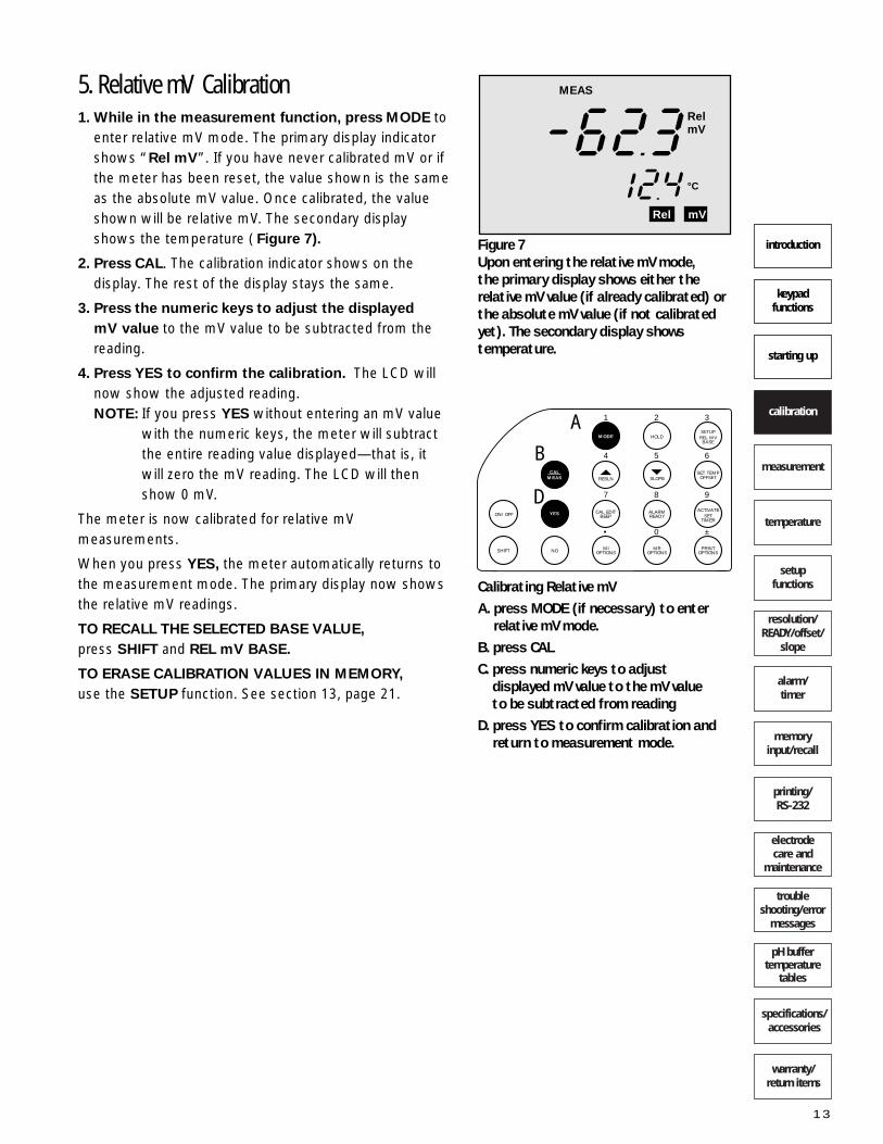
Figure 8In Ion Measurement mode, the primarydisplay (top) shows the ion concentra-tion reading and the secondary display(bottom) shows “Ion”.
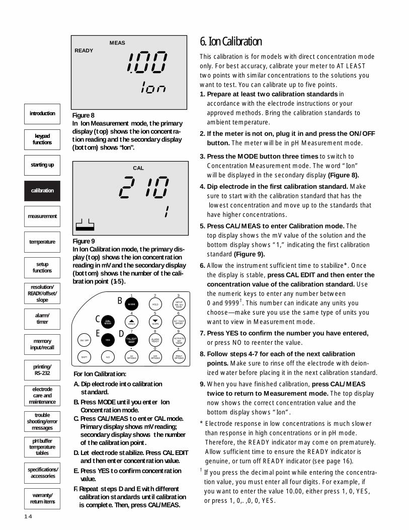
READYMEAS 6. Ion Calibration
This calibration is for models with direct concentration modeonly. For best accuracy, calibrate your meter to AT LEASTtwo points with similar concentrations to the solutions youwant to test. You can calibrate up to five points.1. Prepare at least two calibration standards in
accordance with the electrode instructions or yourapproved methods. Bring the calibration standards toambient temperature.
2. If the meter is not on, plug it in and press the ON/OFF
button. The meter will be in pH Measurement mode.
3. Press the MODE button three times to switch toConcentration Measurement mode. The word “Ion” will be displayed in the secondary display (Figure 8).
4. Dip electrode in the first calibration standard. Makesure to start with the calibration standard that has thelowest concentration and move up to the standards thathave higher concentrations.
5. Press CAL/MEAS to enter Calibration mode. The top display shows the mV value of the solution and thebottom display shows “1,” indicating the first calibrationstandard (Figure 9).
6. Allow the instrument sufficient time to stabilize*. Oncethe display is stable, press CAL EDIT and then enter the
concentration value of the calibration standard. Usethe numeric keys to enter any number between 0 and 9999†. This number can indicate any units youchoose—make sure you use the same type of units youwant to view in Measurement mode.
7. Press YES to confirm the number you have entered,
or press NO to reenter the value.
8. Follow steps 4-7 for each of the next calibration
points. Make sure to rinse off the electrode with deion-ized water before placing it in the next calibration standard.
9. When you have finished calibration, press CAL/MEAS
twice to return to Measurement mode. The top displaynow shows the correct concentration value and the bottom display shows “Ion”.
* Electrode response in low concentrations is much slowerthan response in high concentrations or in pH mode.Therefore, the READY indicator may come on prematurely.Allow sufficient time to ensure the READY indicator is genuine, or turn off READY indicator (see page 16).
† If you press the decimal point while entering the concentra-tion value, you must enter all four digits. For example, if you want to enter the value 10.00, either press 1, 0, YES, or press 1, 0,. ,0, 0, YES.
9
6
3
±
8
5
2
0
7
4
1
•
ACTIVATESET
TIMER
SET TEMPOFFSET
SETUPREL MVBASE
PRINTOPTIONS
MROPTIONS
ALARMREADY
SLOPERESLN
MODE HOLD
CAL EDIT
BEEPYESON/OFF
SHIFT NO MIOPTIONS
CALMEAS
B
C
DE
For Ion Calibration:A. Dip electrode into calibration
standard.B. Press MODE until you enter Ion
Concentration mode.C. Press CAL/MEAS to enter CAL mode.
Primary display shows mV reading;secondary display shows the numberof the calibration point.
D. Let electrode stabilize. Press CAL EDITand then enter concentration value.
E. Press YES to confirm concentrationvalue.
F. Repeat steps D and E with differentcalibration standards until calibrationis complete. Then, press CAL/MEAS.
Figure 9In Ion Calibration mode, the primary dis-play (top) shows the ion concentrationreading in mV and the secondary display(bottom) shows the number of the cali-bration point (1-5).
CAL
warranty/return items
specifications/accessories
pH buffertemperature
tables
trouble shooting/error
messages
electrode care and
maintenance
printing/RS-232
memoryinput/recall
alarm/timer
resolution/READY/offset/
slope
setupfunctions
temperature
measurement
calibration
starting up
keypad functions
introduction
15
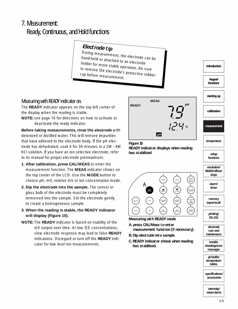
7. Measurement:Ready, Continuous, and Hold functions
Measuring with READY indicator on.The READY indicator appears on the top left corner of the display when the reading is stable. NOTE: see page 16 for directions on how to activate or
deactivate the ready indicator.
Before taking measurements, rinse the electrode withdeionized or distilled water. This will remove impuritiesthat have adhered to the electrode body. If the pH elec-trode has dehydrated, soak it for 30 minutes in a 2M - 4MKCl solution. If you have an ion selective electrode, referto its manual for proper electrode pretreatment.
1. After calibration, press CAL/MEAS to enter the measurement function. The MEAS indicator shows onthe top center of the LCD. Use the MODE button tochoose pH, mV, relative mV or ion concentration mode.
2. Dip the electrode into the sample. The sensor orglass bulb of the electrode must be completelyimmersed into the sample. Stir the electrode gently to create a homogeneous sample.
3. When the reading is stable, the READY indicator
will display (Figure 10).
NOTE: The READY indicator is based on stability of themV output over time. At low ISE concentrations,slow electrode response may lead to false READY
indications. Disregard or turn off the READY indi-cator for low level ion measurements.
9
6
3
±
8
5
2
0
7
4
1
•
ACTIVATESET
TIMER
SET TEMPOFFSET
SETUPREL MVBASE
PRINTOPTIONS
MROPTIONS
ALARMREADY
SLOPERESLN
MODE HOLD
CAL EDITBEEPYESON/OFF
SHIFT NO MIOPTIONS
CALMEAS
A
Measuring with READY modeA. press CAL/Meas to enter
measurement function (if necessary).B. Dip electrode into sample.C. READY indicator shows when reading
has stabilized.
Figure 10READY indicator displays when readinghas stabilized
READYMEAS
pH
°C
pH
Electrode tipDuring measurement, the electrode can behand-held or attached to an electrodeholder for more stable operation. Be sureto remove the electrode’s protective rubbercap before measurement.

warranty/return items
specifications/accessories
pH buffertemperature
tables
trouble shooting/error
messages
electrode care and
maintenance
printing/RS-232
memoryinput/recall
alarm/timer
resolution/READY/offset/
slope
setupfunctions
temperature
measurement
calibration
starting up
keypad functions
introduction
16
Measuring in the continuous modeWhile the READY indicator assures stable readings, the continuous mode provides instantaneous readings forfaster operation. Continuous mode readings, however,are not as stable. To turn off the READY indicator:
1. Press the SHIFT button to access the secondary function of the ALARM/READY key.
2. Press the ALARM/READY key to turn the Ready function off. The display will read “ON“ or “OFF” toindicate whether the READY indicator has been turnedon or off.
3. After calibration, press CAL/MEAS to enter the measurement function. The MEAS indicator shows onthe top center of the LCD. Use the MODE button tochoose pH, mV, relative mV or ion concentration mode.
4. Dip the electrode into the sample. The sensor orglass bulb of the electrode must be completelyimmersed into the sample. Stir the electrode gently to create a homogeneous sample.
5. To turn the Ready function back on, press the SHIFT
button and then the ALARM/READY button.
Holding a reading (HOLD function)This feature lets you freeze the value of the reading for adelayed observation. HOLD can be used any time whenin MEAS mode.1. To hold a measurement, simply press the HOLD key
once while in the measurement function. “HOLD” willappear on the display (Figure 11).
2. To release the held value, press HOLD again. Continue measurements.
9
6
3
±
8
5
2
0
7
4
1
•
ACTIVATESET
TIMER
SET TEMPOFFSET
SETUPREL MVBASE
PRINTOPTIONS
MROPTIONS
ALARMREADY
SLOPERESLN
MODE HOLD
CAL EDITBEEPYESON/OFF
SHIFT NO MIOPTIONS
CALMEAS
9
6
3
±
8
5
2
0
7
4
1
•
ACTIVATESET
TIMER
SET TEMPOFFSET
SETUPREL MVBASE
PRINTOPTIONS
MROPTIONS
ALARMREADY
SLOPERESLN
MODE HOLD
CAL EDITBEEPYESON/OFF
SHIFT NO MIOPTIONS
CALMEAS
A
B
C
Measuring in continuous mode:A. press SHIFT button to access
secondary function of ALARM/READYkey.
B. press ALARM/READY to turn off theready function.
C. press CAL/MEAS to enter measurement function (if necessary).
D. Dip electrode into sample. E. press SHIFT button and ALARM/
READY button to turn the ready function on again.
To freeze a reading:A. Press HOLD button once while in
measurement function. B. Press HOLD again to release.
HOLD
pH
°C
pH
Figure 11Use the HOLD function to freeze your reading.

warranty/return items
specifications/accessories
pH buffertemperature
tables
trouble shooting/error
messages
electrode care and
maintenance
printing/RS-232
memoryinput/recall
alarm/timer
resolution/READY/offset/
slope
setupfunctions
temperature
measurement
calibration
starting up
keypad functions
introduction
17
9
6
3
±
8
5
2
0
7
4
1
•
ACTIVATESET
TIMER
SET TEMPOFFSET
SETUPREL MVBASE
PRINTOPTIONS
MROPTIONS
ALARMREADY
SLOPERESLN
MODE HOLD
CAL EDITBEEPYESON/OFF
SHIFT NO MIOPTIONS
CALMEAS
8. Measuring pHWhen you first turn on the instrument, the meter entersdirectly into pH measurement mode.
1. After calibration, press CAL/MEAS to enter the measurement function. The MEAS indicator shows onthe top center of the LCD.
2. Press the MODE button to choose the pH mode. The“pH” indicator will appear at the bottom of the display.
3. Dip the electrode into the sample. The sensor orglass bulb of the electrode must be completelyimmersed into the sample. Stir the electrode gently to create a homogeneous sample.
4. The primary display will show the pH reading, andthe secondary display will show the temperature. If theREADY indicator is active, it will signal when the read-ing is stable.
9. Measuring mV1. After calibration, press CAL/MEAS to enter the
measurement function. The MEAS indicator shows onthe top center of the LCD.
2. Press the MODE button to choose the mV mode. The“mV” indicator will appear at the bottom of the display.
3. Dip the electrode into the sample. The sensor orglass bulb of the electrode must be completelyimmersed into the sample. Stir the electrode gently to create a homogeneous sample.
4. The primary display will show the mV reading, andthe secondary display will show the current tempera-ture reading. If the READY indicator is active, it will sig-nal when the reading is stable.
NOTE: Resolution is 0.1 mV within a ± 399.9 mV range,and 1 mV up to ±1999 mV. If mV readings are outof range, the display will show “Ur” or “Or” inthe primary display.
9
6
3
±
8
5
2
0
7
4
1
•
ACTIVATESET
TIMER
SET TEMPOFFSET
SETUPREL MVBASE
PRINTOPTIONS
MROPTIONS
ALARMREADY
SLOPERESLN
MODE HOLD
CAL EDITBEEPYESON/OFF
SHIFT NO MIOPTIONS
CALMEAS
BA
B
A
Measuring pH:A. press CAL/MEAS button to enter
measurement function (if necessary).B. press MODE button until meter is in
pH mode.C. Dip electrode in sample.D. READY indicator (if selected on)
shows when reading has stabilized.
Measuring mV:A. press CAL/MEAS button to enter
measurement function (if necessary).B. press MODE button until meter is in
mV mode.C. Dip electrode in sample.D. READY indicator (if selected on)
shows when reading has stabilized.

warranty/return items
specifications/accessories
pH buffertemperature
tables
trouble shooting/error
messages
electrode care and
maintenance
printing/RS-232
memoryinput/recall
alarm/timer
resolution/READY/offset/
slope
setupfunctions
temperature
measurement
calibration
starting up
keypad functions
introduction
18
10. Measuring relative mV
1. After calibration, press CAL/MEAS to enter the Measurement function. The MEAS indicator shows onthe top center of the LCD.
2. Press the MODE button to choose the Relative mVmode. The “Rel mV” indicator will appear at the bot-tom of the display.
3. Dip the electrode into the sample. The sensor orglass bulb of the electrode must be completelyimmersed into the sample. Stir the electrode gently to create a homogeneous sample.
3. The primary display will show the Rel mV reading,and the secondary display will show the temperature. If the READY indicator is active, it will signal when thereading is stable.
Once you enter Rel mV mode, the base value held inmemory (determined in “Calibrating Rel mV”; section 5,page 13) is subtracted from the measured mV value. Thedefault setting for this base value is 0 mV.To calibrate Relative mV (change the base value):1. Press CAL/MEAS while you are in Relative mV
Measurement mode. The display will show CAL.
2. Use the numeric keys to enter the new base value.
3. Press YES to confirm the value and return to theCalibration function. If you make a mistake, press NO
to clear and reenter the value.4. Press CAL/MEAS to return to Measurement function.
All measurements will now be subtracted from thenew base value.
5. To recall the selected base value, press SHIFT andREL mV BASE. The value will show for two secondsand then return to the Measurement function.
9
6
3
±
8
5
2
0
7
4
1
•
ACTIVATESET
TIMER
SET TEMPOFFSET
SETUPREL MVBASE
PRINTOPTIONS
MROPTIONS
ALARMREADY
SLOPERESLN
MODE HOLD
CAL EDITBEEPYESON/OFF
SHIFT NO MIOPTIONS
CALMEAS
B
A
Measuring relative mV:A. press CAL/MEAS button to enter
measurement function (if necessary).B. press MODE button until meter is in
rel mV mode.C. Dip electrode in sample.D. READY indicator (if selected on)
shows when reading has stabilized.
9
6
3
±
8
5
2
0
7
4
1
•
ACTIVATESET
TIMER
SET TEMPOFFSET
SETUPREL MVBASE
PRINTOPTIONS
MROPTIONS
ALARMREADY
SLOPERESLN
MODE HOLD
CAL EDITBEEPYESON/OFF
SHIFT NO MIOPTIONS
CALMEAS
To change base value in relative mV:A. press CAL/MEAS button so display
shows “CAL”.B. use numeric keys to enter new value.C. Press YES to confirm or NO to clear
and reenter.D. Press CAL/MEAS to return to
measurement function.
Quick tip—Rel mV readingsIf you have not calibrated the meter for relative mV, your rel mV reading will be thesame as the standard mV reading.
A-D
C

11. Measuring Ion Concentration1. After calibration, press CAL/MEAS to enter the
Measurement function. The MEAS indicator shows onthe top center of the LCD.
2. Press the MODE button to choose the IonConcentration mode. The secondary display will read“Ion”.
3. Prepare samples as necessary (i.e., add IonicStrength adjuster). Sample preparation varies depend-ing on ion type—see your electrode manual for detailson the specific electrode that you are using.
4. Dip the electrode into the sample. The sensor orglass bulb of the electrode must be completelyimmersed into the sample. For best results, use amagnetic stirrer to ensure a homogenous sample.
5. The primary display will show the current Ion con-
centration reading, while the secondary display willshow the word “Ion”. If the READY indicator is active,it will signal when the reading is stable.
NOTE: Temperature does not display in Ion Measurementmode.
A. press CAL/MEAS button to enter measurement function (if neces-sary).
B. press MODE button until meter isin Ion Concentration mode.
C. Dip electrode in sample.D. READY indicator (if selected on)
shows when reading has stabilized.
warranty/return items
specifications/accessories
pH buffertemperature
tables
trouble shooting/error
messages
electrode care and
maintenance
printing/RS-232
memoryinput/recall
alarm/timer
resolution/READY/offset/
slope
setupfunctions
temperature
measurement
calibration
starting up
keypad functions
introduction
19
Ion tipConcentration readings are not temperaturecompensated. Try to avoid temperaturefluctuations in your standards and samples.
9
6
3
±
8
5
2
0
7
4
1
•
ACTIVATESET
TIMER
SET TEMPOFFSET
SETUPREL MVBASE
PRINTOPTIONS
MROPTIONS
ALARMREADY
SLOPERESLN
MODE HOLD
CAL EDITBEEPYESON/OFF
SHIFT NO MIOPTIONS
CALMEAS
B
A

12. Automatic Temperature Compensation (ATC)and Manual Temperature Compensation
Automatic temperature compensationAutomatic temperature compensation only functions inthe pH measurement mode when the temperature probeis plugged into the meter. 1. For automatic temperature compensation (ATC),
simply plug in the temperature probe in the phone
jack (Figure 12). The ATC indicator will show on theLCD. If the ATC indicator does not show, then the probeis not connected to the meter or is faulty.
You should calibrate your temperature probe when youreplace it. To calibrate the temperature probe:1. Plug the new temperature probe into the phone
jack on the back of the meter.
2. Place the temperature probe and a reference
thermometer in a water bath. Compare the temperature reading on the meter to the temperaturereading on the reference thermometer.
3. Subtract the meter’s temperature reading from
the true temperature to find the required temperatureoffset value.
4. Press the SET TEMP key to select temperature calibration mode.
5. Press the numeric keys to set the desired tempera-
ture value. If you make a mistake, press NO to reset tothe original value, then reenter the desired value again.
6. Press YES to confirm selected temperature. The display will return to its previous mode.
Manual temperature compensationYou can select manual temperature compensation in thepH mode. NOTE: Probe must be disconnected.1. Make sure you are in the measurement function.
You can be in any mode (pH, mV, rel mV, or Ion). PressSET TEMP to select temperature mode. TEMP is displayed at the bottom of the display (Figure 13).
2. Press the numeric keys to set the desired tempera-
ture value. If you make a mistake, press NO to reset tothe original value, then reenter the desired value again.
3. Press YES to confirm selected temperature. The display will return to its previous mode. The meter isnow prepared for temperature compensation withoutthe temperature probe.
For pH buffer/temperature tables, see section 27, page 55.
9
6
3
±
8
5
2
0
7
4
1
•
ACTIVATESET
TIMER
SET TEMPOFFSET
SETUPREL MVBASE
PRINTOPTIONS
MROPTIONS
ALARMREADY
SLOPERESLN
MODE HOLD
CAL EDITBEEPYESON/OFF
SHIFT NO MIOPTIONS
CALMEAS
A B
D
For manual temperature calibration:A. press CAL/MEAS to enter measure-
ment mode (if necessary).B. press SET TEMP to select temp mode. C. press numeric keys to set desired
temperature value.D. press YES to confirm; NO to reenter.
warranty/return items
specifications/accessories
pH buffertemperature
tables
trouble shooting/error
messages
electrode care and
maintenance
printing/RS-232
memoryinput/recall
alarm/timer
resolution/READY/offset/
slope
setupfunctions
temperature
measurement
calibration
starting up
keypad functions
introduction
20
READYMEAS
mV
°CATC
mV
CAL
mV
°C
Temp
ATC INPUTFigure 12Plug temperature probe into ATC jack atback of unit. The ATC indicator will showon LCD (above).
Figure 13
A
warranty/return items
specifications/accessories
pH buffertemperature
tables
trouble shooting/error
messages
electrode care and
maintenance
printing/RS-232
memoryinput/recall
alarm/timer
resolution/READY/offset/
slope
setupfunctions
temperature
measurement
calibration
starting up
keypad functions
introduction
21
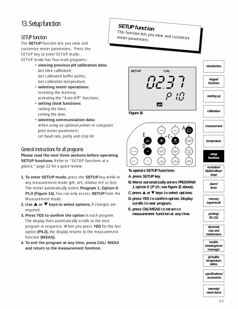
13. Setup function
SETUP functionThe SETUP function lets you view and customize meter parameters. Press the SETUP key to enter SETUP mode.SETUP mode has four main programs:
• viewing previous pH calibration data:
last time calibrated; last calibrated buffer points; last calibration temperature.
• selecting meter operations:
resetting the memory;activating the “Auto-Off” functions.
• setting clock functions:
setting the time;setting the date.
• selecting communication data:
when using an optional printer or computer.print meter parameters;set baud rate, parity and stop bit
General instructions for all programsPlease read the next three sections before operating
SETUP functions. Refer to “SETUP functions at aglance,” page 22 for a quick review.
1. To enter SETUP mode, press the SETUP key while in any measurement mode (pH, mV, relative mV or Ion). The meter automatically enters Program 1, Option 0:
P1.0 (Figure 14). You can only access SETUP from theMeasurement mode.
2. Use or keys to select options, if changes arerequired.
3. Press YES to confirm the option in each program.The display then automatically scrolls to the next program in sequence. When you press YES for the lastoption (P4.2), the display returns to the measurementfunction (MEAS).
4. To exit the program at any time, press CAL/ MEAS
and return to the measurement function.
9
6
3
±
8
5
2
0
7
4
1
•
ACTIVATESET
TIMER
SET TEMPOFFSET
SETUPREL MVBASE
PRINTOPTIONS
MROPTIONS
ALARMREADY
SLOPERESLN
MODE HOLD
CAL EDITBEEPYESON/OFF
SHIFT NO MIOPTIONS
CALMEAS
A
CE
D
To operate SETUP functions:A. press SETUP key.B. Meter automatically enters PROGRAM
1, option 0 (P 1.0; see figure 12 above).C. press or keys to select options.D. press YES to confirm option. Display
scrolls to next program.E. press CAL/MEAS to return to
measurement function at any time.
setupfunctions
SETUP functionThis function lets you view and customizemeter parameters.
SETUP CAL
pH
Figure 14

warranty/return items
specifications/accessories
pH buffertemperature
tables
trouble shooting/error
messages
electrode care and
maintenance
printing/RS-232
memoryinput/recall
alarm/timer
resolution/READY/offset/
slope
setupfunctions
temperature
measurement
calibration
starting up
keypad functions
introduction
22
Setup functions at a glance
9
6
3
±
8
5
2
0
7
4
1
•
ACTIVATESET
TIMER
SET TEMPOFFSET
SETUPREL MVBASE
PRINTOPTIONS
MROPTIONS
ALARMREADY
SLOPERESLN
MODE HOLD
CAL EDITBEEPYESON/OFF
SHIFT NO MIOPTIONS
CALMEAS
When using the setup functions…use the arrow keys highlighted above to toggle between options; or use the numerickeys to input numbers. Remember, certainsetup functions provide information only, andhave no customizing options
Activation DefaultProgram Function Keys Options SettingViewing previous pH calibration data
P1.0 Last calibration time — Indication only —P1.1 Last calibration month — Indication only —P1.2 Last calibration date — Indication only —P1.3 Last calibration year — Indication only —P1.4 Display calibrated buffers or Indication only “- - - -” (no cal)P1.5 Calibration temperature — Indication only 25°C
Selecting meter operations
P2.0 Reset—clears all memory! or ON, OFF OFFP2.1 Optional auto-off or ON, OFF ON
Setting time and date
P3.0 Set time numeric — —P3.1 Set month numeric — —P3.2 Set day numeric — —P3.3 Set year numeric — —
Selecting communication data (RS-232 output)*
P4.0 Print meter parameters or ON, OFF OFFP4.1 Baud rate or 2.4, 4.8, 9.6, 19.2 Kbps 9.6 KbpsP4.2 Parity or 1, 2, 0 2P4.3 Stop bit or 1, 2 2
Press YES to confirm and scroll to each setup function. Press CAL/MEAS to exit at any time.
*The RS-232 settings for the meters with direct concentration mode are permanently set a baudrate of 9600, parity of 2 and stop bit of 1.

warranty/return items
specifications/accessories
pH buffertemperature
tables
trouble shooting/error
messages
electrode care and
maintenance
printing/RS-232
memoryinput/recall
alarm/timer
resolution/READY/offset/
slope
setupfunctions
temperature
measurement
calibration
starting up
keypad functions
introduction
23
Program 1: Viewing previous pH calibration dataProgram 1 tells you the time and date of your last pH calibration. It also lets you see the calibrated buffer valuesand the calibration temperature of your last pH calibration.P1.0 Time of last pH calibration.
Indication only. No options. Press YES to go to next program.P1.1 Month of last pH calibration.
Indication only. No options. Press YES to go to next program.P1.2 Date of last pH calibration.
Indication only. No options. Press YES to go to next program.P1.3 Year of last pH calibration.
Indication only. No options. Press YES to go to next program.P1.4 Display Calibrated pH buffer values:
Lets you view all current calibration points (up to 5). Use or key to scroll through the five calibrations. If youhave not made prior calibrations, the display will show “- - - -”. Press YES to go to next program.P1.5 Display Calibration temperature:
Indicates temperature at the last calibration. Default setting is 25°C. No options to set. Press YES to go tonext program.
SETUP CAL
pH
SETUP CAL
pH
SETUP CAL
pH
SETUP CAL
pH
SETUP CAL
pH
SETUP CAL
Temp
P 1.0: Time of last calibration
P 1.1: Month of last calibration
P 1.2: Date of last calibration
P 1.3: Year of last calibration
P 1.4: Display calibrated buffer valuesP 1.5: Display calibration temperature

warranty/return items
specifications/accessories
pH buffertemperature
tables
trouble shooting/error
messages
electrode care and
maintenance
printing/RS-232
memoryinput/recall
alarm/timer
resolution/READY/offset/
slope
setupfunctions
temperature
measurement
calibration
starting up
keypad functions
introduction
24
Program 2:Selecting meter operations (memory reset; auto-off)Program 2 has two options for customizing:P2.0 Memory reset:
The Memory Reset feature is useful if you want to recali-brate to a different electrode and select entirely newSETUP options. Selecting ON resets all stored meter
data: previous pH, mV and relative mV memory
values; calibration data; and setup data will be lost.
Only the clock memory (month, day, and year) is retained.
If you select ON , the meter immediately switches off,the clock function appears, and you must switch themeter back on before proceeding with any other meterfunctions. All previous settings will return to their defaultsettings.
If reset is required: press or arrows to select ON
and then press YES to activate. See Figure 13. If you want to retain current meter data: select OFF, pressYES and go to the next program.
P2.1 Auto-Off:
To conserve energy, this function automatically shuts offthe meter within 30 minutes after the last key has beenpressed. The clock functions will then appear. Defaultsetting is ON. Use or to select ON or OFF. PressYES to confirm.
Program 3:Setting the time and dateProgram 3 has four options for customizing.P3.0 Display and set time:
use numeric keys to set time. Press YES to confirm.P3.1 Display and set month:
use numeric keys to set month. Press YES to confirm.P3.2 Display and set day:
use numeric keys to set day of month. Press YES to confirm.
WarningBe careful not to accidentally reset your meter.If your meter shows the reset function ON asyou scroll through the setup functions, pressingYES will erase all memory in the meter. Pressthe or arrows to turn reset OFF (shown infigure 13 at right).
P 2.0: Memory reset
SETUP
OFF
P 2.1: Auto off
SETUP
ON
P 3.0: Display and set time
SETUP
P 3.1: Display and set month
SETUP
P 3.2: Display and set day
SETUP

warranty/return items
specifications/accessories
pH buffertemperature
tables
trouble shooting/error
messages
electrode care and
maintenance
printing/RS-232
memoryinput/recall
alarm/timer
resolution/READY/offset/
slope
setupfunctions
temperature
measurement
calibration
starting up
keypad functions
introduction
25
P3.3 Display and set year:
use numeric keys to set year. Press YES to confirm.Meter will continue on to Program 4 on meters with RS-232 option, or return to measurement mode onmeters without RS-232.
Program 4: Selecting communication data (RS-232 output)Program 4 lets you set up the meter communicationparameters when operating it with either your optionalprinter or PC.
NOTE: The RS-232 settings for the pH/Ion/mV/°C models are permanently set a baud rate of9600, parity of 2 and stop bit of 1.
This program has four options. Set these options tomatch your printer or PC requirements.P4.0 Print Meter Parameters:
Press or to select ON or OFF. If you select ON, themeter will download through the RS-232 output the cur-rent date and time; last calibration date and time; elec-trode slope and offset; last calibration temperature;calibration values stored in memory; and relative mV base.
NOTE: To select ON, the meter needs to be attached toyour computer or printer.
P4.1 Baud rate:
Press or to select a baud rate of 2.4, 4.8, 9.6, or19.2 Kbps (2400, 4800, 9600, or 19200 bps). The defaultsetting is 9.6 Kbps (9600 bps). Press YES.
P4.2 Parity:
Press or to select parity of 2 even, 1 odd, or 0 none.Default setting is 2. Press YES to confirm and to go tonext program.P4.3 Stop bit:
Press or to select the stop bit of 1 or 2. Default set-ting is 2. Press YES. Display will automatically return tomeasurement function (MEAS).
P 3.,3: Display and set year
SETUP
P 4.0: Print meter parameters
SETUP
ON
P 4.1: Baud rate
SETUP
P 4.2 Parity
SETUP
P 4.3: Stop bit
SETUP

14. Switching the pH resolution1. Be sure you are in the pH measurement function
(MEAS).
2. Press SHIFT then RESLN. The display will show thelast set resolution (Figure 15).
3. Each time you press SHIFT and RESLN, the meter
automatically toggles to the opposite setting. If youpress the keys and the display shows ON 0.01, thenthe resolution will change to 0.1 for the next measure-ments. If you press the keys and the display shows ON 0.1, the resolution will change to 0.01 for the nextmeasurements.
4. The display will only show for a few seconds and thenreturn to the measurement function (MEAS).
NOTE: In the mV, relative mV, and Ion concentrationmodes, the meter automatically displays the high-est resolution possible up to 31⁄2 digits.
9
6
3
±
8
5
2
0
7
4
1
•
ACTIVATESET
TIMER
SET TEMPOFFSET
SETUPREL MVBASE
PRINTOPTIONS
MROPTIONS
ALARMREADY
SLOPERESLN
MODE HOLD
CAL EDITBEEPYESON/OFF
SHIFT NO MIOPTIONS
CALMEAS
To Switch pH resolutionA. press CAL/MEAS key to enter
measurement function (if necessary).B. press SHIFT key, then RESLN key to
see last set resolution (see Figure 14above).
C. Each time you press SHIFT andRESLN, meter toggles between 0.1 and 0.01.
warranty/return items
specifications/accessories
pH buffertemperature
tables
trouble shooting/error
messages
electrode care and
maintenance
printing/RS-232
memoryinput/recall
alarm/timer
resolution/READY/offset/
slope
setupfunctions
temperature
measurement
calibration
starting up
keypad functions
introduction
26
A
B
B
Figure 15
pH
ON

15. Setting the Ready indicatorThe READY indicator shows on the display when a reading stabilizes. Select YES to turn READY indicator on.Select NO during titration or when you need to detectinstantaneous pH, mV, or ion concentration changes. 1. Be sure you are in the measurement function
(MEAS).
2. Press SHIFT and then press READY. The display willshow the last READY setting (Figure 16).
3. Each time you press SHIFT and READY, the meter
automatically toggles to the opposite setting. If youpress the keys and the display shows ON, then theReady function activates. If you press the keys and thedisplay shows OFF, the Ready indicator deactivates.
4. The display will only show for a few seconds and thenreturn to the measurement function (MEAS).
9
6
3
±
8
5
2
0
7
4
1
•
ACTIVATESET
TIMER
SET TEMPOFFSET
SETUPREL MVBASE
PRINTOPTIONS
MROPTIONS
ALARMREADY
SLOPERESLN
MODE HOLD
CAL EDITBEEPYESON/OFF
SHIFT NO MIOPTIONS
CALMEAS
To set READY indicator:A. press CAL/MEAS key to enter
measurement function (if necessary).B. press SHIFT key, then READY key to
see last READY setting (see Figure 15above).
C. Each time you press SHIFT and READY,meter toggles between ON and OFF.
warranty/return items
specifications/accessories
pH buffertemperature
tables
trouble shooting/error
messages
electrode care and
maintenance
printing/RS-232
memoryinput/recall
alarm/timer
resolution/READY/offset/
slope
setupfunctions
temperature
measurement
calibration
starting up
keypad functions
introduction
27
A
B
C
Figure 16
OFF

16. Setting the audible beepIf the beep function is set to ON, the instrument will beepevery time you press a function key.1. Be sure you are in the Measurement mode (MEAS).
2. Press SHIFT and then press BEEP. The display willshow the last setting (Figure 17).
3. Each time you press SHIFT and BEEP, the meter
automatically toggles to the opposite setting. If youpress the keys and the display shows ON, then thebeep function will go off. If you press the keys and thedisplay shows OFF, the beep function will go back on.
4. The display will only show for a few seconds and thenreturn to the Measurement mode (MEAS).
9
6
3
±
8
5
2
0
7
4
1
•
ACTIVATESET
TIMER
SET TEMPOFFSET
SETUPREL MVBASE
PRINTOPTIONS
MROPTIONS
ALARMREADY
SLOPERESLN
MODE HOLD
CAL EDITBEEPYESON/OFF
SHIFT NO MIOPTIONS
CALMEAS
A
B
B
warranty/return items
specifications/accessories
pH buffertemperature
tables
trouble shooting/error
messages
electrode care and
maintenance
printing/RS-232
memoryinput/recall
alarm/timer
resolution/READY/offset/
slope
setupfunctions
temperature
measurement
calibration
starting up
keypad functions
introduction
28
To set audible beep:A. press CAL/MEAS key to enter
measurement function (if necessary).B. press SHIFT key, then BEEP key to see
last setting. C. Each time you press SHIFT and BEEP,
meter toggles between ON and OFF.
ON
Figure 17

mV
pH
17. OffsetThe offset reading shows how much the meter has tocompensate electronically for the efficiency of the pHelectrode. The offset function shows the pH electrodeoffset value in mV.
The offset is based on the 7.00 pH buffer calibration. Ifyou did not calibrate the 7.00 buffer, the primary displayshows a ±20 mV offset from a base of 0.00 mV.1. Press SHIFT and then OFFSET.
2. The display will then show the offset mV value for afew seconds, and then return to the Measurementmode (Figure 18).
18. Slope The slope function shows the pH electrode slope as apercentage of the theoretical slope based on the Nernstequation. For ion measurements, the slope is displayedas mV per ten fold concentration increase. Slope dis-played is the average slope based on the calibration data.If you have not performed any calibrations, the display willshow 100.0. 1. Press SHIFT and then SLOPE.
2. The display will then show the slope percentage fora few seconds, and then return to the Measurementmode (Figure 19).
9
6
3
±
8
5
2
0
7
4
1
•
ACTIVATESET
TIMER
SET TEMPOFFSET
SETUPREL MVBASE
PRINTOPTIONS
MROPTIONS
ALARMREADY
SLOPERESLN
MODE HOLD
CAL EDITBEEPYESON/OFF
SHIFT NO MIOPTIONS
CALMEAS
A
A
To display OFFSET:A. press SHIFT key and then OFFSET key.B. Display will show offset mV value for a
few seconds and then return to Measurement mode.
warranty/return items
specifications/accessories
pH buffertemperature
tables
trouble shooting/error
messages
electrode care and
maintenance
printing/RS-232
memoryinput/recall
alarm/timer
resolution/READY/offset/
slope
setupfunctions
temperature
measurement
calibration
starting up
keypad functions
introduction
29
Figure 18
pH
9
6
3
±
8
5
2
0
7
4
1
•
ACTIVATESET
TIMER
SET TEMPOFFSET
SETUPREL MVBASE
PRINTOPTIONS
MROPTIONS
ALARMREADY
SLOPERESLN
MODE HOLD
CAL EDITBEEPYESON/OFF
SHIFT NO MIOPTIONS
CALMEAS
To display slope:A. press SHIFT key and then SLOPE key.B. Display will show slope percentage for
a few seconds and then return to Measurement mode.
Figure 19
A
AElectrode tippH electrode slope will decay over time.Check your slope regularly to know whento replace your electrode before it fails.

19. Setting the high and low setpoint alarm1. Press MODE to select the Measurement mode for the
setpoint, i.e. pH, rel mV, or mV.
NOTE: Ion concentration mode does not have high andlow alarms.
2. Press ALARM. If high setpoint has not been entered,the display will show “- - - -” (Figure 20).
3. Press the numeric keys to enter a value for the highsetpoint. If you made a mistake, press NO and enterthe value again. Press YES to confirm and scroll to lowsetpoint selection.
4. If low setpoint has not been entered, the display willshow “- - - -”.
5. Press the numeric keys to enter a value for the lowsetpoint. If you made a mistake, press NO and enterthe value again. Press YES to confirm and exit to Measurement mode.
9
6
3
±
8
5
2
0
7
4
1
•
ACTIVATESET
TIMER
SET TEMPOFFSET
SETUPREL MVBASE
PRINTOPTIONS
MROPTIONS
ALARMREADY
SLOPERESLN
MODE HOLD
CAL EDITBEEPYESON/OFF
SHIFT NO MIOPTIONS
CALMEAS
To set high and low setpoint alarm:A. Select measurement MODE—
pH, mV, or rel mVB. press ALARM key. C. use numeric keys to enter pH value for
high setpoint alarm. Press YES toconfirm and scroll to low setpointalarm; NO to reenter.
D. Use numeric keys to enter pH value forlow setpoint alarm. Press YES to confirm; NO to reenter.
warranty/return items
specifications/accessories
pH buffertemperature
tables
trouble shooting/error
messages
electrode care and
maintenance
printing/RS-232
memoryinput/recall
alarm/timer
resolution/READY/offset/
slope
setupfunctions
temperature
measurement
calibration
starting up
keypad functions
introduction
30
B
A
C-D
pH
pH
Figure 20
To shut off the alarm…go back into ALARM function and press ±key twice. The display will show “---” andthe alarm will shut off.

20. Setting and activating the timerThe instrument provides an internal timer that countsdown from 23 hours 59 minutes, and then gives an audible beep. This function is a timer only and does
not activate any other functions.
1. Be sure you are in the measurement function
(MEAS).
2. Press SHIFT and SET TIMER. If no previous time hasbeen set, the display will show “- - - -”. (Figure 21).
3. Set the desired time from 23 hours 59 minutes. Usethe decimal key to separate hours from minutes. For example: to set one minute, the display shouldshow 00.01.
4. If you make a mistake, press NO and enter the timevalue again. Press YES to confirm and the display willreturn to the Measurement mode (MEAS).
5. To begin the countdown, press ACTIVATE. TheMEAS indicator will flash until the timer reaches 0. The beeper will then sound continuously.
6. To cancel the beeper sound, press any key.7. To stop a countdown in progress, press SHIFT and
SET TIMER, and then press the +/- key. This cancelsthe timer setting. Press YES to return to theMeasurement mode. Press NO to keep the previoustimer setting while stopping a countdown in progress.
9
6
3
±
8
5
2
0
7
4
1
•
ACTIVATESET
TIMER
SET TEMPOFFSET
SETUPREL MVBASE
PRINTOPTIONS
MROPTIONS
ALARMREADY
SLOPERESLN
MODE HOLD
CAL EDITBEEPYESON/OFF
SHIFT NO MIOPTIONS
CALMEAS
A
D,I
B,E,G
HB,G
To Print on Time Interval:A. Press CAL/MEAS key to enter
measurement mode (if necessary).B. Press SHIFT and SET TIMER. C. Use numeric keys to enter time.D. Press YES to confirm; NO to reenter.E. Press ACTIVATE to begin countdown. F. When beeper goes off, press any key to
cancel.
To Cancel Countdown in progress:G. Press SHIFT and SET TIMER keys.H. Press ±key to cancel timer setting.I. Press YES to return to measurement
function; NO to keep previous timersetting while stopping countdown inprogress.
warranty/return items
specifications/accessories
pH buffertemperature
tables
trouble shooting/error
messages
electrode care and
maintenance
printing/RS-232
memoryinput/recall
alarm/timer
resolution/READY/offset/
slope
setupfunctions
temperature
measurement
calibration
starting up
keypad functions
introduction
31
Figure 21
Timer tipsIf you attempt to set the desired time to anamount over 23 hours 59 minutes, themeter will beep and ERROR will flash onthe display.
The timer will not work if meter is turnedoff. Make sure to turn off the AUTO-OFFfunction if you wish the alarm to go offmore than 30 minutes after the meterhas last been operated.

19. Memory input function and optionsData is stored in sets:
• pH and temperature; • mV and temperature (includes ion
concentration measurements)• relative mV and temperature.
This meter can store up to 16 sets of data in any combi-nation of values (pH, mV, and relative mV). For example,you can store 7 pH, 5 mV, and 4 relative mV values. Themeter uses the last-in-first-out (LIFO) method of memorymanagement within each of the three modes, but notbetween the modes when used in combination.
NOTE: pH/Ion/mV/°C meters store up to 13 sets of datain any combination of values. Ion concentrationmeasurements are stored as mV values.
1. During any measurement function (MEAS), press the MI key to input any data into the memory.
2. MEM will flash for a few seconds on the display. The meter stays in measurement function.
3. If the memory is full, the first value stored will be
erased to create space for the new value.
Memory options1st option: Memory input on Ready.
Default is OFF (Figure 22). When turned ON, the meterautomatically sends reading data to memory when theREADY indicator appears in the display. 1. To access the first MI option, press SHIFT and then
MI/OPT.
2. Use the and keys to turn on or off the MI
READY.
3. Press YES to confirm. 4. To get to the second option, press MI/OPT again. To
leave the options and return to measurement function,press CAL/MEAS.
9
6
3
±
8
5
2
0
7
4
1
•
ACTIVATESET
TIMER
SET TEMPOFFSET
SETUPREL MVBASE
PRINTOPTIONS
MROPTIONS
ALARMREADY
SLOPERESLN
MODE HOLD
CAL EDITBEEPYESON/OFF
SHIFT NO MIOPTIONS
CALMEAS
A
B
To input readings into memory.A. press CAL/MEAS key to enter
measurement mode (if necessary).B. press MI key to input any data into
memory.
9
6
3
±
8
5
2
0
7
4
1
•
ACTIVATESET
TIMER
SET TEMPOFFSET
SETUPREL MVBASE
PRINTOPTIONS
MROPTIONS
ALARMREADY
SLOPERESLN
MODE HOLD
CAL EDITBEEPYESON/OFF
SHIFT NO MIOPTIONS
CALMEAS
To access memory input on READYoption:A. press CAL/MEAS key to enter
measurement mode (if necessary).B. press SHIFT key and then MI key. C. use or arrows to turn MI READY
on or off.D. press YES to confirm.E. press MI/OPT to access second
option; press CAL/MEAS to return to measurement function.
warranty/return items
specifications/accessories
pH buffertemperature
tables
trouble shooting/error
messages
electrode care and
maintenance
printing/RS-232
memoryinput/recall
alarm/timer
resolution/READY/offset/
slope
setupfunctions
temperature
measurement
calibration
starting up
keypad functions
introduction
32
OFF
Figure 22
If you turn on MI READY…but you've previously turned the ready functionoff on your meter (see section 15, page 27) themeter will respond with the blinking ERRORindicator. Turn your READY function ON again(see page 27) and then return to MI READY.
A C
D
B B

2nd option: Memory input on time interval.
This option allows you to input data into memory at aselected time interval; for example, if you want to maintain a record of reading every hour. 1. To access the second MI option, press SHIFT, then
MI/OPT, then YES.
2. Use the numeric keys to select the time interval
between automatic inputs to interval. (Figure 23).
3. After entering your numeric value, press YES. The dis-play will return to the measurement function. If youmake a mistake, press NO to reset the value and enteragain.
To remove a previously entered time interval:
1. Press the SHIFT and then the MI key to enterMemory input options.
2. Press YES once to enter the Memory input on timeinterval mode, then press the +/– key to erase timerinterval (“-- - --”).
3. Press YES to confirm.
9
6
3
±
8
5
2
0
7
4
1
•
ACTIVATESET
TIMER
SET TEMPOFFSET
SETUPREL MVBASE
PRINTOPTIONS
MROPTIONS
ALARMREADY
SLOPERESLN
MODE HOLD
CAL EDITBEEPYESON/OFF
SHIFT NO MIOPTIONS
CALMEAS
To access memory input on time intervaloption:A. Press CAL/MEAS key to enter
measurement function (if necessary).B. Press SHIFT key and then MI key. D. Press YES to scroll to second option.E. Use the numeric keys to input the time
interval you wish to print on. PressYES to confirm; No to reenter.
E. press CAL/MEAS to return to measurement function.
warranty/return items
specifications/accessories
pH buffertemperature
tables
trouble shooting/error
messages
electrode care and
maintenance
printing/RS-232
memoryinput/recall
alarm/timer
resolution/READY/offset/
slope
setupfunctions
temperature
measurement
calibration
starting up
keypad functions
introduction
33
MEM
Figure 23
When INPUT TIME INTERVAL is set…The MEAS indicator at the top of the displaywill blink. Resetting your time interval to – – –(see above) will turn this function off and returnyour MEAS indicator to normal.
A,E
D
B C

22. Memory recall function and optionsThis function recalls the previous readings stored in the memory.
1. Set the mode to the parameter that you wish to recall(pH, mV, relative mV, or Ion). Ion values are recalled inmV units.
2. Press the MR key once to recall the last readingstored. MEM will flash on the display.
3. Press the MR key again to recall the next to the lastreading stored, and so on.NOTE: Memory is retained even if the unit is shut off.
4. To prevent accidental clearing of memory, see “Memory clear”, memory recall option 2 below.
5. To exit Memory Recall, press the CAL/MEAS key toreturn to measurement function.
Memory recall options1st option: Memory download to printer
for RS-232 models only.
Default is OFF. Select ON to sort all memorized data bymode and download to RS-232 output. 1. To access the first MR option, press SHIFT and then
MR/OPT.
2. Use the and keys to turn on or off downloadingdata in memory to RS-232 output.
3. Press YES to confirm. 4. To get to the second option, press MI/OPT again. To
leave the options and return to measurement function,press CAL/MEAS.
Option 2: Memory clear.
Select ON to clear all values in memory. Default is OFF.
1. To access the second MR option, press SHIFT, thenMR/OPT, then YES.
2. Use the and keys to clear (ON) or leave (OFF) allvalues in memory.
3. After making your selection, press YES. The displaywill return to the measurement function. Press NO toreset the value and enter again.
9
6
3
±
8
5
2
0
7
4
1
•
ACTIVATESET
TIMER
SET TEMPOFFSET
SETUPREL MVBASE
PRINTOPTIONS
MROPTIONS
ALARMREADY
SLOPERESLN
MODE HOLD
CAL EDITBEEPYESON/OFF
SHIFT NO MIOPTIONS
CALMEAS
A
D
B
To recall readings from memory:A. Set mode to parameter you wish to
recall (pH, mV, rel mV).B. Press MR key to recall last reading
stored.C. Press MR key again to recall next to
last reading, and so on.D. Press CAL/MEAS to return to
measurement function.
9
6
3
±
8
5
2
0
7
4
1
•
ACTIVATESET
TIMER
SET TEMPOFFSET
SETUPREL MVBASE
PRINTOPTIONS
MROPTIONS
ALARMREADY
SLOPERESLN
MODE HOLD
CAL EDITBEEPYESON/OFF
SHIFT NO MIOPTIONS
CALMEAS
To access Memory Recall options:A. press SHIFT and then MR/OPT key to
access options.B. use arrow keys ( and ) to turn on
or off. ON will sort all memorized databy mode and download to RS-232output.
C. press YES to confirm and scroll tonext option.
D. Use arrow keys (and ) to turn onor off. ON will clear all memorized values.
E. Press YES to confirm and return tomeasurement function.warranty/
return items
specifications/accessories
pH buffertemperature
tables
trouble shooting/error
messages
electrode care and
maintenance
printing/RS-232
memoryinput/recall
alarm/timer
resolution/READY/offset/
slope
setupfunctions
temperature
measurement
calibration
starting up
keypad functions
introduction
34
Memory Recall note:you can only access MR in the Measurementmode. When in pH mode, MR recalls onlystored pH values; mV and Ion Concentrationmodes recall only stored mV values; and Rel mVmode recalls only stored relative mV values.
C,E
B,D
A A

Pin number Description1 —2 Transmit Data3 Receive data4 DSR (Data Send Ready)5 GND (Ground)6 —78 RTS (Request to send)9 —
pin number pin numberof meter of printer2 (TXD) 3 (RXD)4 (DSR) 20 (DTR)5 (GND) 7 (GND)
23. Setting up the optional printer and RS-232 output
RS-232 provides an output for transmitting displayedreadings to a printer or computer. The data is supplied inASCII format. ASCII format lets you import data to mostpopular software programs, and to most printers.
Using the meter with a printerMinimum printer requirements to print data:
1. A 9 pin RS-232 serial port on printer.2. Printer should have the option to receive 8 data bits;
even (2), odd (1) or none (0) parity bits; and 1 or 2 stop bits.
NOTE: To print data, connect the meter directly to theprinter. You do not additionally need to connectthe meter to a computer.
Connecting the cable to the meter1. The RS-232 connector is accessible from the back of
the meter (Figure 24).
2. Noting the orientation of the RS-232 connector, plugthe male connector into the RS-232 port on the meter.
3. Tighten the two screws on the sides of the male RS-232 connector.
Connecting the cable to the printer1. Locate the cable port on the printer. If the printer has a
9 pin connector, attach the cable as described above insteps 2-3.
2. If the printer has a 25 pin connector, you must use a25 pin to 9 pin converter. Attach the cable (with converter) as described in steps 2-3 above.
NOTE: For the meter and printer to properly communi-cate and transfer data, the pin configurations onboth units must match. To determine this, com-pare the pin configuration of your printer (see theprinter manual) with the pin configuration of thismeter (see tables at right). Since there is noindustry standard for the pin configuration onprinters, you might need to configure the pins.This can require soldering. Also, jumper boxes and cable-making products are available frommost computer stores.
warranty/return items
specifications/accessories
pH buffertemperature
tables
trouble shooting/error
messages
electrode care and
maintenance
printing/RS-232
memoryinput/recall
alarm/timer
resolution/READY/offset/
slope
setupfunctions
temperature
measurement
calibration
starting up
keypad functions
introduction
35
GND RS232 DC
Figure 24
If the printer has a 25 pin connector, a25 pin to 9 pin connector will have to beused. Use the following configuration:
The meter has a 9 pin female RS-232connector with this configuration:

Using the meter with a printer to downloadstored memoryUse the first MR key option to download all memory to aprinter.
1. To access the first MR option, press SHIFT and thenMR/OPT.
2. Use the and keys to select ON to sort all memo-rized data by mode and download to RS-232 output.
3. Press YES to confirm. All data will download to theprinter.
4. To get to the second option (lets you clear all valuesstored in meter memory), press MI/OPT again. To leavethe options and return to measurement function, pressCAL/MEAS.
warranty/return items
specifications/accessories
pH buffertemperature
tables
trouble shooting/error
messages
electrode care and
maintenance
printing/RS-232
memoryinput/recall
alarm/timer
resolution/READY/offset/
slope
setupfunctions
temperature
measurement
calibration
starting up
keypad functions
introduction
36
9
6
3
±
8
5
2
0
7
4
1
•
ACTIVATESET
TIMER
SET TEMPOFFSET
SETUPREL MVBASE
PRINTOPTIONS
MROPTIONS
ALARMREADY
SLOPERESLN
MODE HOLD
CAL EDITBEEPYESON/OFF
SHIFT NO MIOPTIONS
CALMEAS
To print stored memory:A. press SHIFT and then MR/OPT key to
access options.B. use arrow keys ( and ) to select
ON to sort all memorized data bymode and download to printer.
C. press YES and then CAL/MEAS toconfirm return to measurement func-tion.
C
B
A A
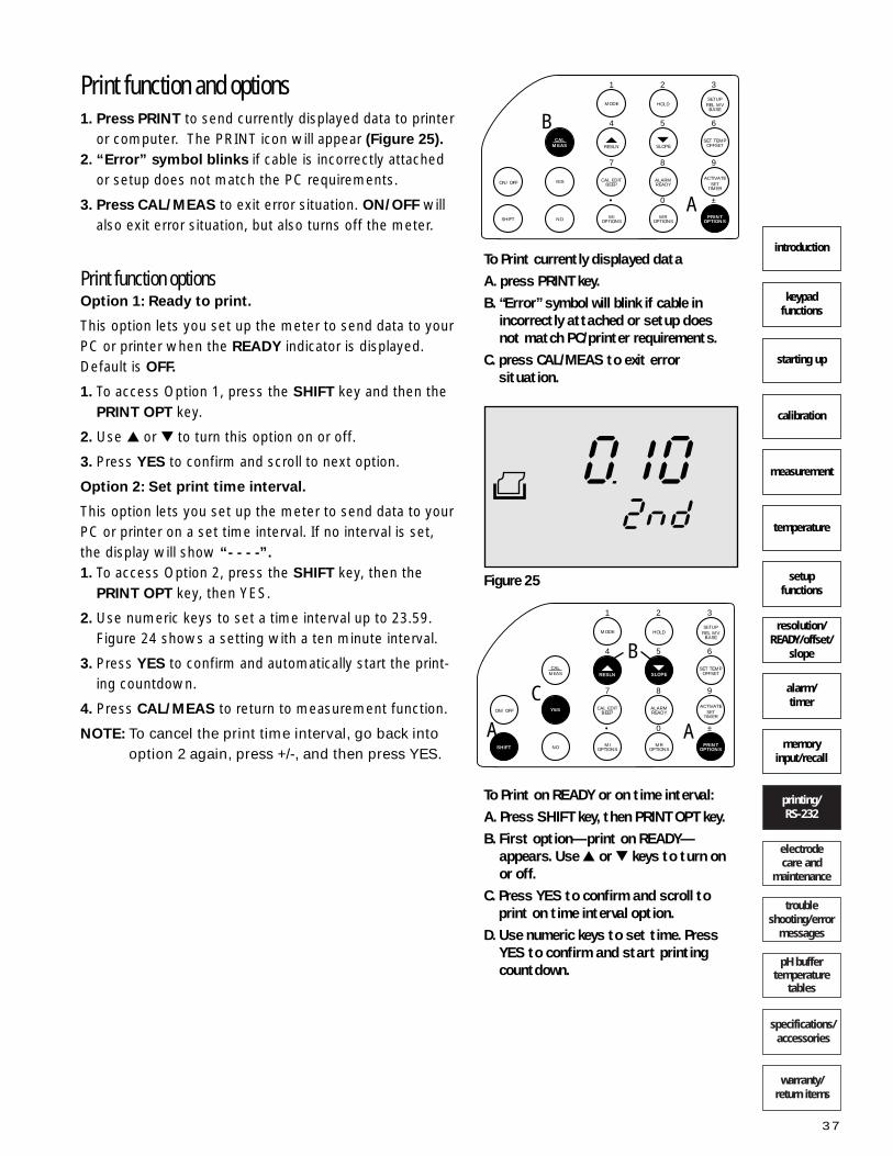
warranty/return items
specifications/accessories
pH buffertemperature
tables
trouble shooting/error
messages
electrode care and
maintenance
printing/RS-232
memoryinput/recall
alarm/timer
resolution/READY/offset/
slope
setupfunctions
temperature
measurement
calibration
starting up
keypad functions
introduction
37
9
6
3
±
8
5
2
0
7
4
1
•
ACTIVATESET
TIMER
SET TEMPOFFSET
SETUPREL MVBASE
PRINTOPTIONS
MROPTIONS
ALARMREADY
SLOPERESLN
MODE HOLD
CAL EDITBEEPYESON/OFF
SHIFT NO MIOPTIONS
CALMEAS
A
B
To Print currently displayed dataA. press PRINT key.B. “Error” symbol will blink if cable in
incorrectly attached or setup doesnot match PC/printer requirements.
C. press CAL/MEAS to exit error situation.
9
6
3
±
8
5
2
0
7
4
1
•
ACTIVATESET
TIMER
SET TEMPOFFSET
SETUPREL MVBASE
PRINTOPTIONS
MROPTIONS
ALARMREADY
SLOPERESLN
MODE HOLD
CAL EDITBEEPYESON/OFF
SHIFT NO MIOPTIONS
CALMEAS
To Print on READY or on time interval:A. Press SHIFT key, then PRINT OPT key.B. First option—print on READY—
appears. Use or keys to turn on or off.
C. Press YES to confirm and scroll toprint on time interval option.
D. Use numeric keys to set time. PressYES to confirm and start printingcountdown.
Figure 25
AA
C
B
Print function and options 1. Press PRINT to send currently displayed data to printer
or computer. The PRINT icon will appear (Figure 25).
2. “Error” symbol blinks if cable is incorrectly attachedor setup does not match the PC requirements.
3. Press CAL/MEAS to exit error situation. ON/OFF willalso exit error situation, but also turns off the meter.
Print function optionsOption 1: Ready to print.
This option lets you set up the meter to send data to yourPC or printer when the READY indicator is displayed.Default is OFF.
1. To access Option 1, press the SHIFT key and then thePRINT OPT key.
2. Use or to turn this option on or off.
3. Press YES to confirm and scroll to next option.
Option 2: Set print time interval.
This option lets you set up the meter to send data to yourPC or printer on a set time interval. If no interval is set,the display will show “- - - -”.
1. To access Option 2, press the SHIFT key, then thePRINT OPT key, then YES.
2. Use numeric keys to set a time interval up to 23.59.Figure 24 shows a setting with a ten minute interval.
3. Press YES to confirm and automatically start the print-ing countdown.
4. Press CAL/MEAS to return to measurement function.
NOTE: To cancel the print time interval, go back intooption 2 again, press +/-, and then press YES.

Using the meter with a computer and theOakton DAS for Windows®
IntroductionThe OAKTON DAS is the NEXT GENERATION in easy touse Data Acquisition Software. The features offered are:
• Bi-directional communications so you can monitor,control, and operate virtually all the meter functions and the data acquisition operations directly from yourPC—even while you operate other programs!
• Faster data sampling times for more frequent sam-pling when values change rapidly.
• Easily sets up and configures your meter from your
PC to ensure the meter and PC are using the samecommunications parameters.
• View measured values directly on the screen withautomatic updating.
• Displays alarm and timer status at the PC.
• Filing options for importing your data file to virtually
any spread sheet or word processing application.
NOTE: Make sure the meter and mouse are connectedBEFORE you start. It is also preferable to turn off the meter’s Auto Off function in the Set-upprogram P 2.1 (see page 24 for instructions). This lets you avoid error messages indicating themeter is in STAND BY mode when the auto off isactivated from a period of no activity (30 min.)
warranty/return items
specifications/accessories
pH buffertemperature
tables
trouble shooting/error
messages
electrode care and
maintenance
printing/RS-232
memoryinput/recall
alarm/timer
resolution/READY/offset/
slope
setupfunctions
temperature
measurement
calibration
starting up
keypad functions
introduction
38
Minimum computer requirementsto run OAKTON DAS for Windows® 386 and above that can run MicrosoftWindows® 95 or higher, a CD-ROM drive,and a hard disk with approximately 500 MBfree disk space. EGA Monitor and above. Mouse and Mouse Driver Software. 9 pin PC Serial Port Connecting Cable(OAKTON 35615-09 or other).

warranty/return items
specifications/accessories
pH buffertemperature
tables
trouble shooting/error
messages
electrode care and
maintenance
printing/RS-232
memoryinput/recall
alarm/timer
resolution/READY/offset/
slope
setupfunctions
temperature
measurement
calibration
starting up
keypad functions
introduction
39
Loading the OAKTON Data Acquisition SoftwareTo run the DAS software from the CD-ROM:1. Use the Windows File Manager or Explorer. Select "File
Run" and then type "A:\OAKDAS". To run the DAS software from your hard drive: 1. Use File Manager or Explorer to create a new directory
and copy the contents of the disk to this new directory.2. Switch to your new directory and double click the
"OAKDAS" file or icon to run the application.
MAIN MENU OPTIONSSix items are displayed at the top of the screen just belowthe header. these are the MAIN MENU OPTIONS (Figure 26). From LEFT to RIGHT these are:
1. FILE- Selecting this reveals a window with the optionslabeled SETTINGS, RUN... , OPEN, CLOSE, and EXIT.OPEN and CLOSE are not active until there are datafiles available to open or close (OPEN and CLOSE willappear in grey scale to indicate this).
2. METER PARAM- Selecting this opens a read only dia-log box that indicates all the current settings. Thesesettings will be downloaded to the meter when the pro-gram begins running (once ‘RUN......” is selected in theFILE options).
3. CAL PARAM- Selecting this lets the meter communi-cate calibration information to the PC. This option can-not be opened until ‘RUN’ is selected.
4. ABOUT- Selecting this and double clicking Enter opensa read only dialog box that identifies the DAS software,and copy right and trade mark information.
5. - Select this to minimize the DAS to an on screenICON labeled ‘OAKTON D.A.S.’ ‘DAS SOFTWARE’.Use this feature when you want to go to another appli-cation software and still keep the OAKTON DAS readyfor use. Single Clicking on the ICON lets you edit thename under the ICON. Hold the click on the ICON tomove the ICON to new positions on the screen.
6. - This symbol identifies the button that lets youquickly resize the DAS window between full size and asmaller prespecified size. When the window is full sizethis symbol appears as: . This is useful to quicklyresize the window when running DAS at the same timeas other applications.
Figure 26
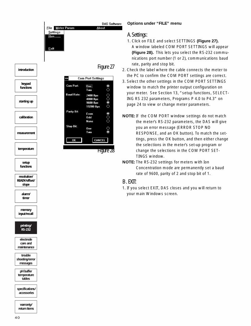
warranty/return items
specifications/accessories
pH buffertemperature
tables
trouble shooting/error
messages
electrode care and
maintenance
printing/RS-232
memoryinput/recall
alarm/timer
resolution/READY/offset/
slope
setupfunctions
temperature
measurement
calibration
starting up
keypad functions
introduction
40
Options under “FILE” menu
A. Settings: 1. Click on FILE and select SETTINGS (Figure 27).
A window labeled COM PORT SETTINGS will appear(Figure 28). This lets you select the RS-232 commu-nications port number (1 or 2), communications baudrate, parity and stop bit.
2. Check the label where the cable connects the meter tothe PC to confirm the COM PORT settings are correct.
3. Select the other settings in the COM PORT SETTINGSwindow to match the printer output configuration onyour meter. See Section 13, “setup functions, SELECT-ING RS 232 parameters, Programs P 4.0 to P4.3” onpage 24 to view or change meter parameters.
NOTE: If the COM PORT window settings do not matchthe meter’s RS-232 parameters, the DAS will giveyou an error message (ERROR STOP NORESPONSE, and an OK button). To match the set-tings, press the OK button, and then either changethe selections in the meter’s set-up program orchange the selections in the COM PORT SET-TINGS window.
NOTE: The RS-232 settings for meters with IonConcentration mode are permanently set a baudrate of 9600, parity of 2 and stop bit of 1.
B . EXIT:1. If you select EXIT, DAS closes and you will return to
your main Windows screen.
Figure 27
Figure 28

C. RUN:This opens the actual DAS operating mode. 1. You will first see a LINKING WITH METER window that
warns you that the meter will be reconfigured accordingto the Configuration file (Figure 29). The configurationfile combines the COM PORT SETTINGS and the MeterPARAM files.
2. Select the STOP button to cancel the DAS operatingmode. If you select STOP you return to the main DASscreen.
3. Or, select the continue button to load the configurationsettings and open the DAS operating mode. If youselect continue, the DAS will either:• show a window that displays each parameter that is
loading into the meter. • give you a warning ERROR STOP NO RESPONSE
with an OK button to press.
If the see a window that displays the meter
parameters loading into the meter, wait until theDISPLAY window with “UPDATING DATA” appears.This window will flash to indicate the readings arecurrent and updating constantly. (Figure 30). Tworows of function buttons will appear at the bottom of the screen. The CAL PARAM option in the headerwill also darken, indicating it is available as a selec-tion. DAS is now running.
If you see a warning, “ERROR STOP NO RESPONSE,”
clicking the OK button in the ERROR window will give amessage: “linking error check cable and communicationsparameters” and cause the DAS to go back to the mainscreen.
To correct the error message, select SETTINGS under the FILE options above and reset the COM PORT SETTINGS. Or, reset the meter’s RS 232 parameters tomatch the selections in the COM PORT SETTINGS win-dow. Select RUN under the FILE options and continue. If you still have error messages, call your OAKTONDistributor for advice.
warranty/return items
specifications/accessories
pH buffertemperature
tables
trouble shooting/error
messages
electrode care and
maintenance
printing/RS-232
memoryinput/recall
alarm/timer
resolution/READY/offset/
slope
setupfunctions
temperature
measurement
calibration
starting up
keypad functions
introduction
41
Figure 29
Figure 30

DATA FILE MANAGEMENTThe OAKTON DAS software lets you log data directlyto your computer or to download readings that havebeen stored in your meter's memory. Logging datadirectly to your computer allows faster logging ratesand unlimited file sizes—-see“Storing Directly toComputer File” below.
Logging data to your meter’s memory allows you tostore readings even when you don't have immediateaccess to a computer; however, you are limited to 16 readings (13 with the pH/Ion/°C meter)—see“Downloading Memory from Meter” on page 44).
Storing directly to computer fileOPEN Window (under the FILE menu)
While the DAS is in the RUN mode (see page 41),the OPEN and CLOSE operations under the FILEoptions are available. The OPEN option lets youstore data for retrieval and use in other applicationsoftware programs.
When you select the OPEN option under the FILEmenu, a DATA window opens that displays the cur-rent readings, date and time. OPEN file, CLOSE fileand LOG TIME buttons also appear (Figure 31).
OPEN FILE button
Selecting OPEN FILE opens a window with a textarea for you to name a file, and three optional fileformats to select (Figure 32).
1. Type a file name in the “Enter File Name” area. Type a new name for a new data file. Type anexisting name to append an existing data file.
2. Use the file format selection feature to quicklyformat your files so they can more easily beimported to your application software. If you areusing Lotus or Excel, select the correct format.Select TXT file format for general purpose use inother word processing applications.
3. After selecting a file name and file format, clickOPEN. • If you used an existing file name, when you click
OPEN you will see a message that asks it youwant to append the existing file. Click yes to addthe data you are collecting to the existing file inchronological order. Click no to start a separatedata file; you then need to name a new file inthe“Enter File Name” area.
42
Figure 32
Figure 31
warranty/return items
specifications/accessories
pH buffertemperature
tables
trouble shooting/error
messages
electrode care and
maintenance
printing/RS-232
memoryinput/recall
alarm/timer
resolution/READY/offset/
slope
setupfunctions
temperature
measurement
calibration
starting up
keypad functions
introduction
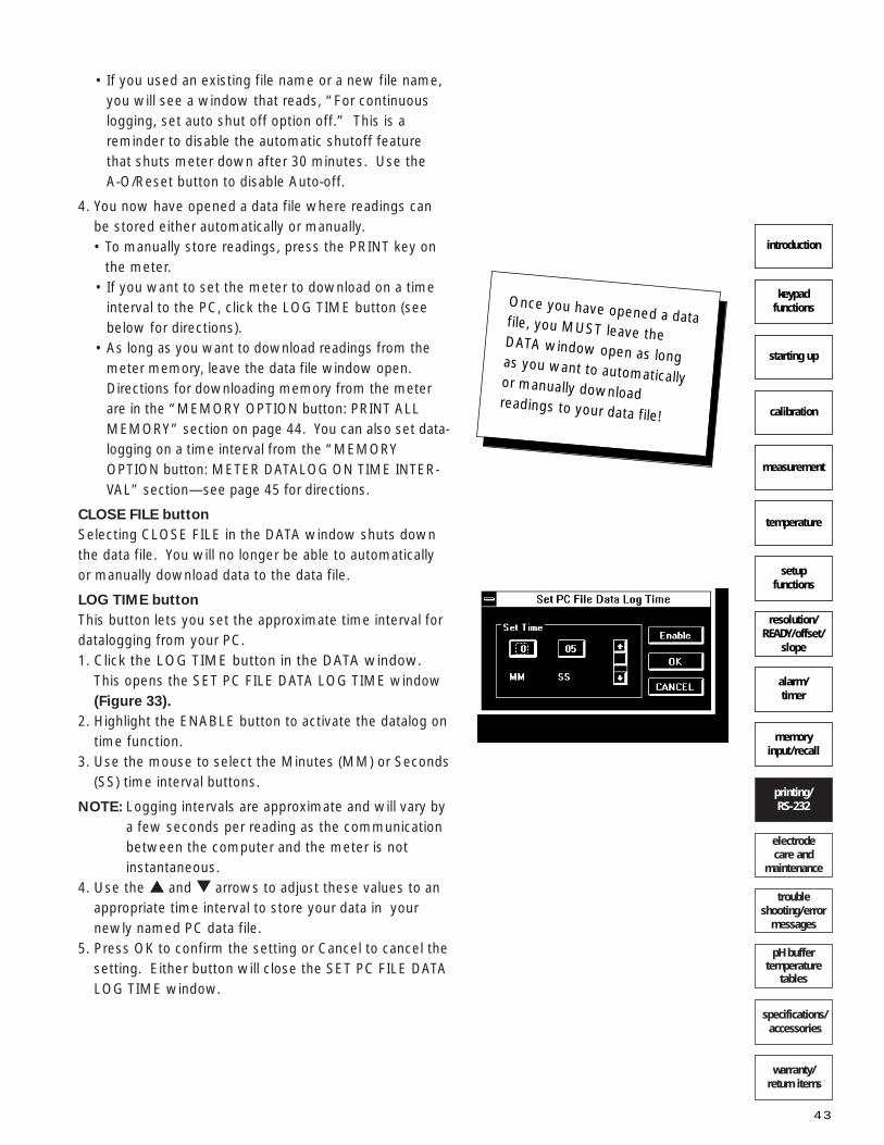
• If you used an existing file name or a new file name,you will see a window that reads, “For continuouslogging, set auto shut off option off.” This is areminder to disable the automatic shutoff featurethat shuts meter down after 30 minutes. Use the A-O/Reset button to disable Auto-off.
4. You now have opened a data file where readings canbe stored either automatically or manually.• To manually store readings, press the PRINT key on
the meter. • If you want to set the meter to download on a time
interval to the PC, click the LOG TIME button (seebelow for directions).
• As long as you want to download readings from themeter memory, leave the data file window open.Directions for downloading memory from the meterare in the “MEMORY OPTION button: PRINT ALLMEMORY” section on page 44. You can also set data-logging on a time interval from the “MEMORYOPTION button: METER DATALOG ON TIME INTER-VAL” section—see page 45 for directions.
CLOSE FILE button
Selecting CLOSE FILE in the DATA window shuts downthe data file. You will no longer be able to automaticallyor manually download data to the data file.
LOG TIME button
This button lets you set the approximate time interval fordatalogging from your PC.1. Click the LOG TIME button in the DATA window.
This opens the SET PC FILE DATA LOG TIME window(Figure 33).
2. Highlight the ENABLE button to activate the datalog ontime function.
3. Use the mouse to select the Minutes (MM) or Seconds(SS) time interval buttons.
NOTE: Logging intervals are approximate and will vary bya few seconds per reading as the communicationbetween the computer and the meter is notinstantaneous.
4. Use the and arrows to adjust these values to anappropriate time interval to store your data in yournewly named PC data file.
5. Press OK to confirm the setting or Cancel to cancel thesetting. Either button will close the SET PC FILE DATALOG TIME window.
warranty/return items
specifications/accessories
pH buffertemperature
tables
trouble shooting/error
messages
electrode care and
maintenance
printing/RS-232
memoryinput/recall
alarm/timer
resolution/READY/offset/
slope
setupfunctions
temperature
measurement
calibration
starting up
keypad functions
introduction
43
Once you have opened a datafile, you MUST leave the DATA window open as long as you want to automaticallyor manually download readings to your data file!
Figure 33

Downloading memory from meterTo download readings stored in the meter’s memory, click the MEMORY OPTIONS button on the bottom of the computer screen. NOTE: You can store readings to memory either through
the MEM IN button located on the meter keypad,or from the MEM IN button located at the bottomof the computer screen.
The MEMORY OPTIONS button also lets you clear allmemory in the meter, select Datalog on Ready indicator,or select Datalog on time interval from the meter.
MEMORY OPTIONS button.
Selecting this button will open a series of four windowswith options for you to select. These are:
A. Memory release opt: PRINT ALL MEMORY
This window lets you download all memory in the meter.
1. Select ON or OFF for the PRINT ALL MEMORYoperation to download all readings in the meter’smemory to the PC (Figure 34).
2. If you press ON and then press OK, the computerdisplays the Meter Memory Data Window. Thiswindow displays all readings stored in the meter. It has a SAVE button that lets you save the storeddata to an existing file, and a CANCEL button to exitthis window. • If you have set up an existing file, when you press
SAVE the data will download into that file.• If you have not set up an existing file, when you
press SAVE you will see a window stating, “Nofile is opened” with an OK button. See the“OPEN FILE” section on page 42 for directions onhow to create and open a file for data storagefrom the meter.
NOTE: if no memory is stored in the meter, the MeterMemory Data Window will display, “All memo-ries are empty.”
3. Press OK or CANCEL to exit the PRINT ALL MEM-ORY window and move on to the next window.
warranty/return items
specifications/accessories
pH buffertemperature
tables
trouble shooting/error
messages
electrode care and
maintenance
printing/RS-232
memoryinput/recall
alarm/timer
resolution/READY/offset/
slope
setupfunctions
temperature
measurement
calibration
starting up
keypad functions
introduction
44
Figure 34

B. Memory Release Opt: CLEAR ALL MEMORY
This window lets you select ON or OFF to clear allmemory and erase the readings stored in the meter’smemory (Figure 35).
1. Select ON or OFF to select whether to clear all mem-ory data from the meter .
2. Press OK to enter this setting into the system. Press the CANCEL button to cancel this change to the setting.
C. Memory In Opt: DATALOG ON READY
This window lets you select DATALOG ON READYfunction ON or OFF. If this function is turned on, themeter stores readings in the meter’s memory eachtime the READY indicator displays (indicates a stablereading) (Figure 36).
1. Select ON or OFF to select whether to turn on DATALOG ON READY.
NOTE: If you select ON while the READY indicator isturned off, you will see a window that says to turn the READY indicator on. See page 49 fordirections.
2. Press OK to enter this setting into the system. Press the CANCEL button to cancel this change tothe setting.
D. METER DATALOG ON TIME INTERVAL
This button lets you set up the DAS and meter to automatically datalog to the PC on a time interval (Figure 37). This lets you accumulate large data files for manipulation later.
1. Click the ENABLE/DISABLE button to toggle itbetween ENABLE and DISABLE. ENABLE indicatesthat the meter will datalog on a time interval; DISABLE indicates that the meter will not datalog on a time interval.
2. When ENABLE is displayed, use the mouse to selecthours (HH) or minutes (MM), and then use the and arrow keys to enter the datalog time interval.
NOTE: Logging intervals are approximate and will vary bya few seconds per reading as the communicationbetween the computer and the meter is notinstantaneous.
3. Press the OK button to confirm all selections. To returnto previous settings, press the CANCEL button.
4. To stop datalogging, open the Meter Data Log On TimeInterval window again, then select DISABLE and OK.
warranty/return items
specifications/accessories
pH buffertemperature
tables
trouble shooting/error
messages
electrode care and
maintenance
printing/RS-232
memoryinput/recall
alarm/timer
resolution/READY/offset/
slope
setupfunctions
temperature
measurement
calibration
starting up
keypad functions
introduction
45
Figure 36
Figure 37
Figure 35

OAKTON DAS FUNCTIONSCAL PARAM
Select CAL PARAM at the top of the screen to view awindow that shows all the calibration data (Figure 38).
NOTE: Although you can view calibration data from thescreen, you need to perform calibration functionsfrom your benchtop meter.
The “Electrode Parameters” window shows all the cali-bration data: Last Calibration date, Last Calibration Time,pH Electrode Slope, pH Electrode Offset, relative mVbase, a list of the calibration buffers used in calibration,and Last Calibration Temperature.
NOTE: You may save this file as ELE.TXT, a text file thatyou can import to your other application softwarefor a record of the calibration. Click YES or NO toselect the save function. Click OK to close thiswindow. The file will save to the directory wherethe DAS is located.
warranty/return items
specifications/accessories
pH buffertemperature
tables
trouble shooting/error
messages
electrode care and
maintenance
printing/RS-232
memoryinput/recall
alarm/timer
resolution/READY/offset/
slope
setupfunctions
temperature
measurement
calibration
starting up
keypad functions
introduction
46
Figure 38

DAS CONTROL BUTTONSThe DAS control buttons are located along the bottom ofthe screen.
OFF button: Careful: this causes the DAS to stop running and return tothe main screen of the DAS. To return to the DAS run-ning mode, select RUN under the FILE menu.
MEAS button: Use this to exit calibration functions and return to mea-surement mode from the PC.
MODE button:
Use this to select measurement mode from the PC:either pH, mV, Rel mV or Concentration. A window noting the mode change will appear for an instant.
HOLD button:
Freezes the readings from the PC. Press it again and itreturns the meter and DAS displays to updated readings.
MEM IN button:
Memory Input. Use this to manually store a reading inmemory from the PC.
MEM OPT button:
SEE “DATA FILE MANAGEMENT” on page 44.
SET TEMP button
This opens a window for setting the temperaturevalue for manual pH temperature compensation(Figure 39).
1. Click and hold the mouse and drag the slider tothe temperature position you want. Use thearrow keys on the sides of the slider for finerincrementation. Watch the numeric display ofthe selected value to choose the appropriatemanual temperature setting.
2. Press OK to enter this setting into the system.Or, press the CANCEL button to cancel this change.
warranty/return items
specifications/accessories
pH buffertemperature
tables
trouble shooting/error
messages
electrode care and
maintenance
printing/RS-232
memoryinput/recall
alarm/timer
resolution/READY/offset/
slope
setupfunctions
temperature
measurement
calibration
starting up
keypad functions
introduction
47
Figure 39

warranty/return items
specifications/accessories
pH buffertemperature
tables
trouble shooting/error
messages
electrode care and
maintenance
printing/RS-232
memoryinput/recall
alarm/timer
resolution/READY/offset/
slope
setupfunctions
temperature
measurement
calibration
starting up
keypad functions
introduction
48
ALARM button
This button opens a series of two windows thatlet you select the high and low alarm set points.(Figure 40). The measurement mode that themeter and DAS system are in determines thealarm type shown in the window.
For example: the pH measurement mode lets youset pH alarms, the mV measurement mode letsyou set the mV alarms, etc.
NOTE: There are no alarm settings in Ion concentrationmode.
The following description uses the SET high pH Alarms asan example, but all modes follow the same principles.
A. SET pH HIGH ALARM window has a slider to control the selection of the alarm value. 1. Press the DISABLE/ENABLE button at the BOT-
TOM of the window until ENABLE is displayed.
2. Place the arrow over the shaded slider buttonand position it at the value for the pH High alarmObserve the numerical display at the top of thewindow to verify this value. Use the arrow keysat the sides of the slider for finer incrementation.
3. Press OK to enter this setting into the systemPress the CANCEL button to cancel this change.When you press the OK or Cancel button, thewindow will close and the SET pH LOW ALARMwindow will appear.
B. SET pH LOW ALARM window operates exactly thesame as the SET pH HIGH ALARM window.
NOTE: You cannot set the High pH Alarm setpoint lowerthan the Low pH Alarm setpoint.
SET TIMER button
Clicking this button causes the SET TIMER window toappear (Figure 41). To set the timer:1. Press the DISABLE/ENABLE button until ENABLE is
displayed . 2. Click on the hours (HH ) or Minutes (MM) buttons to
select the intervals you want to adjust.Use the mousearrow on the and arrows on the display to setthe time for the timer.
3. Press OK to enter this setting into the system. Pressthe CANCEL button to cancel this change to the set-ting. Whether you press the OK or Cancel button, thewindow will close.
Figure 41
Figure 40

warranty/return items
specifications/accessories
pH buffertemperature
tables
trouble shooting/error
messages
electrode care and
maintenance
printing/RS-232
memoryinput/recall
alarm/timer
resolution/READY/offset/
slope
setupfunctions
temperature
measurement
calibration
starting up
keypad functions
introduction
49
ACTIVATE button
Starts the timer countdown. NOTE: If there is no time interval set for the timer, an
error message “METER TIMER NOT SET. GO SETTIMER’ is displayed with an OK button. Press theOK button to close the message window.
When a time interval is set, you will see a brief message,“please wait meter is enabling the timer”. After thismessage disappears, the timer is running. A continuousbeep will signal when the time is up. A message windowstating, “timer status timer is activated” and an OK but-ton will appear. Click the OK button or press the activatebutton on the meter to deactivate the beep.
NOTE: To disable timer, click the SET TIMER button andclick the DISABLE/ENABLE button to DISABLE.
READY button
Opens a window that lets you select whether the Readyindicator is on or off (Figure 42).
1. Use the mouse to select Ready ON or OFF. 2. Press OK to enter this setting into the system. Press
the CANCEL button to cancel this change to the set-ting. Whether you press the OK or Cancel button, thewindow will close.
RESLN button
Opens a window that lets you select the pH resolution as 0.1 or 0.01pH (Figure 43).
1. Use the mouse to select 0.1 or 0.01pH. 2. Press OK to enter this setting into the system. Press
the CANCEL button to cancel this change to the set-ting. Whether you press the OK or Cancel button, thewindow will close.
BEEP button
Opens a window that lets you turn on or off the meter’s audible beep that confirms function activation(Figure 44). This does not affect the alarm or timer beep;these will still audibly beep at the appropriate times.1. Use the mouse to select beep ON or OFF. 2. Press OK to enter this setting into the system. Press
the CANCEL button to cancel this change to the set-ting. Whether you press the OK or Cancel button, thewindow will close.
Figure 44
Figure 43
Figure 42

DRIFT/MIN button
Opens a window that displays the electrode’s drift perminute. This is a view only window. This window dis-plays the electrode drift in the current measurementmode. For example: if the meter is set for the pH modeelectrode drift is displayed in pH/min; if it is set for mV, relmV or ion modes, electrode drift is displayed in mV/min.Press OK to close the window (Figure 45).
AUTO OFF AND RESET button
Opens a series of two windows: A. The first Window lets you select whether the AutoShut Off function is ON or OFF (Figure 46).1. Use the mouse to select auto off ON or OFF. 2. Press OK to enter this setting into the system.
Press the CANCEL button to cancel this change tothe setting. Whether you press the OK or Cancelbutton, the window will close.
B. The Second Window lets you select whether theRESET is ON or OFF (Figure 47). Resetting the meter is a quick way to reconfigure meter for a newelectrode.
NOTE: Selecting ON and pressing the OK button willerase ALL memory and calibrations, and resetthe meter to all default parameters! Themeter will shut off and go to standby mode. A message window will appear indicating themeter is in standby mode. If you press the OKbutton, you will return to the main DAS screen.Select RUN under FILE options and Continuein the next window to return to DAS in the run-ning mode.
1. Use the mouse to select Reset ON or OFF. 2. Press OK to enter this setting into the system.
Press the CANCEL button to cancel this change tothe setting. Whether you press the OK or Cancelbutton, the window will close.
warranty/return items
specifications/accessories
pH buffertemperature
tables
trouble shooting/error
messages
electrode care and
maintenance
printing/RS-232
memoryinput/recall
alarm/timer
resolution/READY/offset/
slope
setupfunctions
temperature
measurement
calibration
starting up
keypad functions
introduction
50
Figure 45
Figure 46
Figure 47

DATE/TIME button
Opens a series of two windows that let you set the dateand time shown on the DAS. The first Window is theSET DATE window (Figure 48).
1. Use the mouse to select year (YY) , month (MM) or day(DD) for adjustment.
2. Select the and arrows to change the values dis-played.
3. Press OK to enter this setting into the system Pressthe CANCEL button to cancel this change to the set-ting. Whether you press the OK or Cancel button, thewindow will close.and the second window will display.
The second window is the SET TIME window.
1. Use the mouse to select Hours (HH) minutes (MM) orseconds (SS) for adjustment.
2. Use the mouse to operate the and arrows tochange the values displayed.
3. Press OK to enter this setting into the system Pressthe CANCEL button to cancel this change to the set-ting. Whether you press the OK or Cancel button, thewindow will close.
DATE and TIME DISPLAY buttons
The last two buttons in the lower right hand corner areread only displays of the date and time.
EXITING OAKTON DASCLOSE (under FILE options)
Select CLOSE in FILE options. The display window andbuttons will close. Then select EXIT under FILEOPTIONS.
warranty/return items
specifications/accessories
pH buffertemperature
tables
trouble shooting/error
messages
electrode care and
maintenance
printing/RS-232
memoryinput/recall
alarm/timer
resolution/READY/offset/
slope
setupfunctions
temperature
measurement
calibration
starting up
keypad functions
introduction
51
Excel, Microsoft—Reg TM Microsoft Corp.Lotus 123—Reg TM Lotus Development Co.
Figure 48

warranty/return items
specifications/accessories
pH buffertemperature
tables
trouble shooting/error
messages
electrode care and
maintenance
printing/RS-232
memoryinput/recall
alarm/timer
resolution/READY/offset/
slope
setupfunctions
temperature
measurement
calibration
starting up
keypad functions
introduction
52
24. pH Electrode care and maintenanceBecause your pH electrode is susceptible to dirt and conta-mination, clean it every one to three months depending onthe extent and condition of use. NOTE: for Ion Selective Electrode care, consult the
instruction manual included with your electrode.
pH electrode storageFor best results, always keep the pH bulb wet. Use the pro-tective rubber cap filled with electrode storage solution tostore your electrode. Also, you can store in a pH 4 bufferwith 1/100 part of saturated KCl. Other pH buffers are OKfor storage, but NEVER use distilled water for storage.
After measuring1. Rinse the pH electrode and reference junction in de-ion-
ized water.2. Store the electrode as recommended above in
“Storage,” or as recommended by the manufacturer.
To reuse the pH electrode:Rinse the liquid junction with de-ionized water and tap dry—never wipe electrode dry.
NOTE: If this does not restore electrode to normalresponse, see “Reactivating the electrode” below.
pH electrode cleaningSalt deposits: dissolve the deposits by immersing the elec-trode in tap water for ten to fifteen minutes. Then thor-oughly rinse with distilled water.Oil/grease film: wash electrode pH bulb gently in somedetergent and water. Rinse electrode tip with distilled water,or use a general purpose electrode cleaner.Clogged reference junction: heat a diluted KCl solution to60 to 80°C. Place the sensing part of the electrode into theheated solution for about 10 minutes. Allow the electrode tocool in some unheated KCl solution.Protein deposits: prepare a 1% pepsin solution in 0.1M ofHCl. Set the electrode in the solution for five to ten minutes.Rinse the electrode with distilled water.

warranty/return items
specifications/accessories
pH buffertemperature
tables
trouble shooting/error
messages
electrode care and
maintenance
printing/RS-232
memoryinput/recall
alarm/timer
resolution/READY/offset/
slope
setupfunctions
temperature
measurement
calibration
starting up
keypad functions
introduction
53
Reactivating the pH electrodeIf stored and cleaned properly, your pH electrode should beready for immediate use. However, a dehydrated bulb maycause sluggish response. To rehydrate the bulb, immersethe electrode in a pH 4 buffer solution for 10 to 30 minutes.If this fails, the electrode requires reactivation. Never
touch or rub glass bulb. Contact builds up an electro-
static charge.
1. Dip or stir the pH electrode in alcohol for 5 minutes.2. Leave the electrode in tap water for 15 minutes.3. Dip and stir the electrode in concentrate acid (such
as HCl or H2S04) for five minutes.4. Repeat step 2.
5. Dip and stir in strong base (NaOH) for five minutes.6. Leave for 15 minutes in distilled or deionized water.7. Now test with standard calibration buffer solutions
to see if the electrode yields acceptable results. Youmay repeat step 3 through 6 up to three times for bet-ter response. If the response does not improve, thenyour electrode is no longer functioning—replace with anew electrode. Call your OAKTON Distributor.
WARNING: Only qualified persons proficient with the safe handlingof dangerous chemicals should perform the procedurebelow. Provide proper containers, fume hoods, ventilation, and waste disposal. Safety goggles and protective clothing must be worn while performing thisprocedure. If possible, replace with another electrodeinstead of performing this reactivation procedure.

warranty/return items
specifications/accessories
pH buffertemperature
tables
trouble shooting/error
messages
electrode care and
maintenance
printing/RS-232
memoryinput/recall
alarm/timer
resolution/READY/offset/
slope
setupfunctions
temperature
measurement
calibration
starting up
keypad functions
introduction
54
25. Error messages
Problem Cause SolutionPower on but no A. AC adapter is not A. Connect AC adapterdisplay. connected properly. properly.
B. AC adapter supply B. Replace AC adaptervoltage is not enough. with new one.
Unstable reading. A. Electrode not A. Place electrodedeep enough in deeper in sample.sample.
B. Broken electrode. B. Replace electrode.
C. External noise or C. Remove or switchinduction caused by off interfering motor.nearby electric motor.
D. Dirty electrode. D. Clean electrode.Reactivate, if needed.
Slow response. Dirty electrode. Clean electrode. Reactivate, if needed.
LCD display Indicates Cause SolutionErr. 1 Memory write Unit too old Turn meter off(on primary error. (> 10 years) and then on.display) or hardware Return if needed.+ 2 short beeps. failure.
Err. 2 Memory Hardware Turn meter off(on primary checksum failure. and then on.display) error. Return if needed.+ 2 short beeps.
Err.3 ADC error. Hardware Turn meter off(on primary fault. and then on.display) Return if needed.+ 2 short beeps.
Err. 4 Keypad error. One or more Turn meter off(on primary keys on the and then on.display) keypad are Return if needed.+ 2 short beeps. stuck.
Err. 5 Real time Hardware Turn meter off(on primary clock failure. failure or unit and then on.display) > 10 years old. Return if needed.+ 2 short beeps.
No display ADC error. Hardware Turn meter off+ 2 short beeps. fault. and then on.
Return if needed.
Err. Wrong keypad. You pressed Release key. annunciator the wrong Select correct + 2 short beeps. keypad. function.
Electrode icon Calibration Wrong buffer Check if right& buffer icon error. used during buffer selected blink. Err calibration. OR input correct annunciator on. buffer value OR+ 2 short beeps. use fresh buffer
solution.
Printer icon Not able to Printer is off Check cable& Err print. or cable is connections andannunciator faulty. printer settings.blink
+ 2 short beeps
If it is necessary to return a meter, please see “Return ofItems,” page 58.
26. Troubleshooting

27. pH buffer/temperature table.Temperature pH buffer values
°C °F 4.01 7.00 10.00
0 32 4.01 7.12 10.335 41 4.01 7.09 10.25
10 50 4.00 7.06 10.1815 59 4.00 7.04 10.1120 68 4.00 7.02 10.0525 77 4.01 7.00 10.0030 86 4.01 6.99 9.9535 95 4.02 6.98 9.9240 104 4.03 6.98 9.8845 113 4.04 6.97 9.8550 122 4.06 6.97 9.8255 131 4.07 6.98 9.8060 140 4.09 6.98 9.7770 158 4.12 6.99 9.7380 176 4.16 7.00 9.6990 194 4.20 7.02 9.66
warranty/return items
specifications/accessories
pH buffertemperature
tables
trouble shooting/error
messages
electrode care and
maintenance
printing/RS-232
memoryinput/recall
alarm/timer
resolution/READY/offset/
slope
setupfunctions
temperature
measurement
calibration
starting up
keypad functions
introduction
55
When to use the pH buffer/temperature table:Refer to this table when using manual temperature compensation (see section 12,page 20). Use CAL/EDIT function (see section 4,page 11) to adjust the buffer calibration to thevalue corresponding to your temperature.

28. Specifications
pH slope adj. range: 80 to 120%
Calibration: Up to 5 customizable pH points or concentration values (all push button calibration). pH calibration also features auto buffer recognition at 5 common pH buffer values. Meter alsofeatures push button adjustment for temperature
Rel. mV offset range: ±1999 mV
Recorder output: ±1999 mV (directly proportional to input)
RS-232: 9 pin female, selectable baud rates 2.4, 4.8, 9.6 kbps (2400, 4800, 9600, 19200 bps); selectable stop bit (1 or 2); selectable parity (odd/1, even/2, or none/0). Ion selective benchtopmeters have a fixed baud rate of 9600, stop bit of 2, and parity of 1
Printer requirements: Accepts serial output as per RS-232 specifications above
Computer requirements: 386 and above that can run Microsoft Windows® 95 or higher, a 3.5" (1.44 MB) or 5.25" (1.2 MB) disk drive, hard disk with approx. 500 KB free disk space, EGA monitor or above, 9-pin serial port connecting cable, mouse.
Input impedance: >1012 Ω
Display: Dual display (measurement plus temp and mode annunciators)
Connectors: pH/mV use BNC connector; temperature uses mini-phono plug; RS-232 uses 9 pin female; recorder uses mini-pin (submini phono plug)
Operating temperature: 0 to 50°C (32 to 122°F)
Power: 9 V, 500 mA AC adapter (110 or 220 VAC)
Dimensions: Meter only: 9" x 7" x 23⁄8" (229 x 178 x 61 mm); Boxed: 151⁄2" x 31⁄2" x 10" (394 x 89 x 254 mm)
Weight: 1.25 lbs/0.6 kg (meter only); 3 lbs/1.4 kg (boxed)
warranty/return items
specifications/accessories
pH buffertemperature
tables
trouble shooting/error
messages
electrode care and
maintenance
printing/RS-232
memoryinput/recall
alarm/timer
resolution/READY/offset/
slope
setupfunctions
temperature
measurement
calibration
starting up
keypad functions
introduction
56
Mode pH Temperature mV Ion
Range -2.00 to 15.99 0.0 to 100.0°C –1999 to 1999 mV 0 to 9999(same for rel mV) concentration units
Resolution 0.01 or 0.1 pH 0.1°C 0.1mV up to ±399.9mV ±1 least 1mV beyond ±399.9mV significant digit
Accuracy ±0.01 pH ±0.5°C ±0.2mV up to ±399.9mV ±0.5% of±2mV beyond ±399.9mV reading
Calibration Up to 5 buffers Offset 0.1°C Offset up to ±1999 mV Up to 5 pointsTemperature ATC or manual — — —Compensation 0.0 to 100.0°C

29. AccessoriesCall your OAKTON® Distributor for ordering information.
35615-05 ATC probe.35615-09 Printer cable for RS-232 printer output, 9 pin35615-07 Replacement 110 VAC power adapter.35615-08 220 VAC power adapter.35801-00 OAKTON® replacement general purpose pH electrode.35801-71 OAKTON® replacement “All-in-one”, sealed general purpose pH electrode,
with built-in temperature element.35801-70 OAKTON® “All-in-one” refillable general purpose pH electrode with temperature
element.35801-72 OAKTON® “All-in-one”, sealed double junction pH electrode with built-in
temperature element.00654-01 pH 1.68 calibration buffer00654-00 pH 4.00 calibration buffer.00654-04 pH 7.01 calibration buffer.00654-08 pH 10.01 calibration buffer.00654-12 pH 12.45 calibration buffer.35622-00 Printer, 110 VAC35622-05 Printer, 220 VAC
Consult your OAKTON® Distributor for a complete selection of pH and ORP electrodes, solutions,holders, and accessories.NOTE: Remember to check the temperature calibration when replacing the ATC probe or
when using with an OAKTON® “All-in-One” combined pH and temperature probe. See section 12, page 20, “Automatic Temperature Compensation (ATC) and ManualTemperature Compensation.”
warranty/return items
specifications/accessories
pH buffertemperature
tables
trouble shooting/error
messages
electrode care and
maintenance
printing/RS-232
memoryinput/recall
alarm/timer
resolution/READY/offset/
slope
setupfunctions
temperature
measurement
calibration
starting up
keypad functions
introduction
57

30. WarrantyWe warrant this product to be free from significant deviations in material and workmanship for a period ofone year from date of purchase. If repair or adjustment isnecessary and has not been the result of abuse or misusewithin the one year period, please return, freight prepaid,and correction will be made without charge. Out of warranty products will be repaired on a charge basis.
31. Return of itemsAuthorization must be obtained from your OAKTONDistributor before returning items for any reason. Whenapplying for authorization, please include data regardingthe reason the items are to be returned.NOTE: We reserve the right to make improvements indesign, construction, and appearance of products withoutnotice.
warranty/return items
specifications/accessories
pH buffertemperature
tables
trouble shooting/error
messages
electrode care and
maintenance
printing/RS-232
memoryinput/recall
alarm/timer
resolution/READY/offset/
slope
setupfunctions
temperature
measurement
calibration
starting up
keypad functions
introduction
58