DUAL DIGITAL pH / ORP / mV CONTROLLER - Liquid … Manuals/Controllers...complex algorithm that...
28
DUAL DIGITAL pH / ORP / mV CONTROLLER DPH-4 USERS GUIDE DPH-4 Instruction manual PAGE 1
-
Upload
truongtuyen -
Category
Documents
-
view
222 -
download
1
Transcript of DUAL DIGITAL pH / ORP / mV CONTROLLER - Liquid … Manuals/Controllers...complex algorithm that...
DUAL DIGITAL
pH / ORP / mV
CONTROLLER
DPH-4USERS GUIDE
DPH-4 Instruction manual PAGE 1

TABLE OF CONTENTS
SPECIFICATIONS . . . . . . . . . . . . . . . . 3
INTRODUCTION . . . . . . . . . . . . . . . . . 5
Normal dosing (nor) 6
Normal Proportional dosing (no.P) 6
Adaptive proportional dosing. (Ad.P) 6
INSTALLATION . . . . . . . . . . . . . . . . . 9
Instrument . . . . . . . . . . . . . . . . . . . 9
Wiring of the DPH-4 10
Signal output 11
Electrodes 11
Starting up the Instrument. 11
CONFIGURATION . . . . . . . . . . . . . . . . 12
Looking at menus and values . . . . . . . . . 12
Default values for the DPH-4 instrument 13
Saving Values in Configuration. . . . . . . . . 14
OPERATION . . . . . . . . . . . . . . . . . . . 19
Initial check of the DPH-4. . . . . . . . . . . . 19
Calibrating the DPH-4 with a simulator. . . . . 19
Selecting Mode of Operation. . . . . . . . . . 21
Using Timers. . . . . . . . . . . . . . . . . . 27
WARRANTY . . . . . . . . . . . . . . . . . . . . 28
PAGE 2 DPH-4 Instruction manual
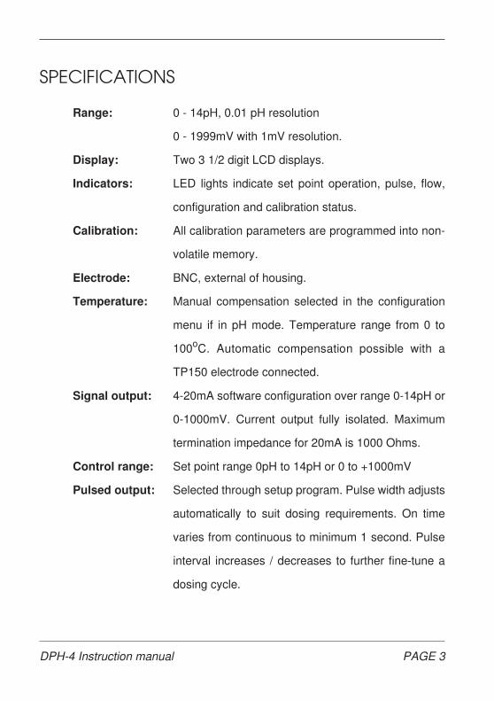
SPECIFICATIONS
Range: 0 - 14pH, 0.01 pH resolution
0 - 1999mV with 1mV resolution.
Display: Two 3 1/2 digit LCD displays.
Indicators: LED lights indicate set point operation, pulse, flow,
configuration and calibration status.
Calibration: All calibration parameters are programmed into non-
volatile memory.
Electrode: BNC, external of housing.
Temperature: Manual compensation selected in the configuration
menu if in pH mode. Temperature range from 0 to
100oC. Automatic compensation possible with a
TP150 electrode connected.
Signal output: 4-20mA software configuration over range 0-14pH or
0-1000mV. Current output fully isolated. Maximum
termination impedance for 20mA is 1000 Ohms.
Control range: Set point range 0pH to 14pH or 0 to +1000mV
Pulsed output: Selected through setup program. Pulse width adjusts
automatically to suit dosing requirements. On time
varies from continuous to minimum 1 second. Pulse
interval increases / decreases to further fine-tune a
dosing cycle.
DPH-4 Instruction manual PAGE 3
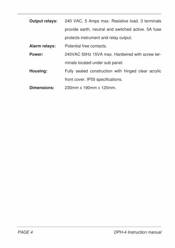
Output relays: 240 VAC, 5 Amps max. Resistive load. 3 terminals
provide earth, neutral and switched active. 5A fuse
protects instrument and relay output.
Alarm relays: Potential free contacts.
Power: 240VAC 50Hz 15VA max. Hardwired with screw ter-
minals located under sub panel.
Housing: Fully sealed construction with hinged clear acrylic
front cover. IP55 specifications.
Dimensions: 230mm x 190mm x 120mm.
PAGE 4 DPH-4 Instruction manual

INTRODUCTION
The DPH-4 instrument contains two separate pH/ORP controllers
facilitating an efficient installation. The two instruments are electrically
isolated to ensure reliable performance under all conditions. Each con-
troller can be independently configured for pH or ORP and up or down
SET POINT control. The operating modes of both instruments are pro-
grammed with rotary encoders incorporating a push button to accept
dialled values. A second encoder allows the operator to configure the
controller for various timing modes to prevent abnormal levels of chemical
dosing or overshooting of the set points.
LED’s show the operational status of the instrument or setup program
currently available. Pushing the encoder prepares for performing configu-
rations or calibrations. Rotating the encoder clockwise and pushing again
enters the configuration menu to set up the instrument. Rotating the
encoder anticlockwise and pushing enters the calibration menu. You scroll
through menus with the encoder knob and once a menu is selected values
are increased or decreased by rotating the encoder knob clock- or
FIG 1 DPH-4 CONTROLLER
DPH-4 Instruction manual PAGE 5
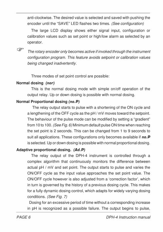
anti-clockwise. The desired value is selected and saved with pushing the
encoder until the “SAVE” LED flashes two times. (See configuration)
The large LCD display shows either signal input, configuration or
calibration values such as set point or high/low alarm as selected by an
operator.
F The rotary encoder only becomes active if invoked through the instrument
configuration program. This feature avoids setpoint or calibration values
being changed inadvertently.
Three modes of set point control are possible:
Normal dosing (nor)
This is the normal dosing mode with simple on/off operation of the
output relay. Up or down dosing is possible with normal dosing.
Normal Proportional dosing (no.P)
The relay output starts to pulse with a shortening of the ON cycle and
a lengthening of the OFF cycle as the pH / mV moves toward the setpoint.
The behaviour of the pulse mode can be modified by setting a “gradient”
from 10 to 100. (See Fig. 6) Minimum default pulse ON time when reaching
the set point is 2 seconds. This can be changed from 1 to 9 seconds to
suit all applications. These configurations only becomes available if no.P
is selected. Up or down dosing is possible with normal proportional dosing.
Adaptive proportional dosing. (Ad.P)
The relay output of the DPH-4 instrument is controlled through a
complex algorithm that continuously monitors the difference between
actual pH / mV and set point. The output starts to pulse and varies the
ON/OFF cycle as the input value approaches the set point value. The
ON/OFF cycle however is also adjusted from a ‘correction factor’, which
in turn is governed by the history of a previous dosing cycle. This makes
for a fully dynamic dosing control, which adapts for widely varying dosing
conditions. (See Fig. 7)
Dosing for an excessive period of time without a corresponding increase
in pH is recognized as a possible failure. The output begins to pulse,
PAGE 6 DPH-4 Instruction manual

preventing overdosing. The pulse output exhibits a very wide duty cycle.
The ON and OFF times are both dynamic, both varying from 1 to 60
seconds. Up or down dosing is possible with “Adaptive proportional
Dosing”.
F The DPH-4 program prevents gross overdosing in the event of a process
upset or electrode failure. (Adaptive mode only)
Temperature compensation (pH mode only) is set for 20oC by default.
This can be changed in the configuration program from 0 to 100oC. A
TP150 temperature electrode connected to the terminals enables the
option for automatic compensation.
The DPH-4 features an alarm relay with potential free contacts. Low
and high alarm points are set in the configuration menu.
FIG 2 LED's show different conditions.
DPH-4 Instruction manual PAGE 7

The flow switch input is configured to operate as N/O or N/C. (normally
open or normally closed) The output relay is locked out and the relay LED
flashes if no flow is detected. The flow LED indicates this condition. The
two inputs can be parallel if only using one flow switch.
The inherent accuracy and range configuration of the 4-20mA constant
current output together with full electrical isolation make it possible to
interface into a microprocessor, logic controller or data logger to further
expand the combination of installations with the DPH-4.
Timers can also be used to further protect against accidental overdosing.
If activated, TIMER 1 is started every time the instrument calls for dosing
with an adjustable on time from 1 minute to 2 hours. If the set time is
exceeded without the set point relay deactivating, TIMER 2 takes over,
locks out the relay for the configured off time and indicates this with a
flashing red “TIMER/SET” LED. TIMER 2 is adjusted from 1 to 30
minutes.
If looped mode (lOOP) is selected and the instrument still calls for
dosing after TIMER 2 has run out TIMER 1 will take over and repeat the
operation. The alarm relay can be configured to activate during TIMER 2.
In terminal mode (n.LP) TIMER 1 is triggered when the instrument calls
for dosing. If the dosing takes place within the set time the instrument will
function as normal. If for some reason the condition for dosing remains
and TIMER 1 runs out the dosing relay is disabled and indicates the state
with a flashing LED. “SEt” is displayed when pushing the timer encoder
to indicate a lockout condition. Push for 1 second to clear the lockout.
Dosing is again resumed.
The alarm relay is always activated if the controller is in terminal lockout.
The flow input will always disable the dosing relay and activate the
alarm relay even if the timers are disabled making this feature useful for
no flow or low level alarms. This condition is indicated with the flow LED
red and the relay LED flashing.
PAGE 8 DPH-4 Instruction manual

INSTALLATION
Instrument
Select a position for the controller to be mounted on a wall, not facing into
direct sunlight and protected from the weather elements as much as possible.
The DPH-4 should be installed near the treatment plant. Maximum length of
the co-axial cable used should not exceed 10 metres because of the very high
input impedance characteristic of a pH electrode.
The metal electrodes used for redox measurements are of much lower
resistance and longer coaxial cables can be used without any special
precautions.
Insert a round headed screw into the panel where the instrument is to
be attached. This screw determines the centre of the instrument location.
(Fig.3) Slide the instrument over the slot opening at the back, check that
the unit hangs level and secure it with two screws inserted through the
slots at the two bottom corners.
F Do not drill any holes into the enclosure to install the controller.
FIG 3 Attaching the DPH-4 to a wall
DPH-4 Instruction manual PAGE 9

Wiring of the DPH-4
It is imperative that all connections are wired through the cable gland
and the transparent lid is always tight to ensure that no corrosive liquids
inadvertently splash into the instrument.
The 3 terminals for the SET POINT provide an earth, neutral and
switched 240VAC (active) . A metering pump, solenoid valve or other
device requiring 240V can be connected.
A suppression capacitor is already connected to filter electrical spikes
caused by switching solenoid valves.
The alarm relay terminal has potential free contacts. (N/O C N/C)
You need to determine the N/O or N/C of a flow switch when connecting
for proper configuration later on. Polarity does not matter when wiring a
flow switch.
F The Set point relay terminals connect to earth, neutral and switched active
240V. (240VAC is supplied to these terminals when activated by the set point.)
FIG 4 Terminal layout for the DPH-4
PAGE 10 DPH-4 Instruction manual

Signal output
The 4-20 mA signal current output can be used for event recording or
to expand the control facilities for additional relay contacts. This output
can be wired directly to a computer interface without causing earth loop
problems. Correct polarity wiring is essential.
The current signal can also be configured to drive a metering pump with
a signal input. (See Fig. 9)
F Correct polarity has to be observed when connecting the 4-20mA signal
output.
Electrodes
The co-axial cable used to connect the electrode to the DPH-4 must be
of the type supplied with a carbon sleeve between the centre core and
shield as any standard co-axial cable will cause a very erratic reading. An
impedance converter must be used if the location between electrode and
controller exceeds 10 meters. Special consideration also must be given
when placing an electrode in a treatment bath or pool. The point of injection
of neutralising agent and placement of the electrode (distance between
them) largely determines the dosing characteristics of the DPH-4.
F Only use special co-axial cable to connect a pH electrode to the DPH-4.
Starting up the Instrument.
After you have installed the instrument and checked all the wiring and
connections open the isolation valves to the sensor to allow water flow
across it. Plug the power cord into the supply and switch on the DPH-4.
The “RUN/CONFIG” LED will light up green and the digital display shows
the measured input value.
F To quickly change the setpoint push and hold down the encoder until the
green LED flashes and the present setpoint is displayed. Release and dial
a new setpoint. Push again until the SAVE LED flashes two times.
DPH-4 Instruction manual PAGE 11
CONFIGURATION
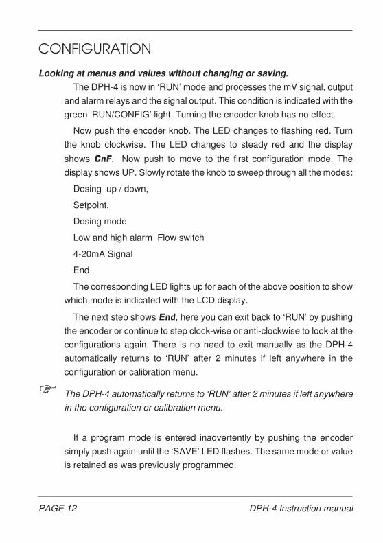
Looking at menus and values without changing or saving.
The DPH-4 is now in ‘RUN’ mode and processes the mV signal, output
and alarm relays and the signal output. This condition is indicated with the
green ‘RUN/CONFIG’ light. Turning the encoder knob has no effect.
Now push the encoder knob. The LED changes to flashing red. Turn
the knob clockwise. The LED changes to steady red and the display
shows CnF. Now push to move to the first configuration mode. The
display shows UP. Slowly rotate the knob to sweep through all the modes:
Dosing up / down,
Setpoint,
Dosing mode
Low and high alarm Flow switch
4-20mA Signal
End
The corresponding LED lights up for each of the above position to show
which mode is indicated with the LCD display.
The next step shows End, here you can exit back to ‘RUN’ by pushing
the encoder or continue to step clock-wise or anti-clockwise to look at the
configurations again. There is no need to exit manually as the DPH-4
automatically returns to ‘RUN’ after 2 minutes if left anywhere in the
configuration or calibration menu.
F The DPH-4 automatically returns to ‘RUN’ after 2 minutes if left anywhere
in the configuration or calibration menu.
If a program mode is entered inadvertently by pushing the encoder
simply push again until the ‘SAVE’ LED flashes. The same mode or value
is retained as was previously programmed.
PAGE 12 DPH-4 Instruction manual

Default values for the DPH-4 instrument
The DPH-4 is shipped with default values programmed in non-volatile
memory.
mV MODE
Dosing = UP UP
Setpoint = 500 500
Dosing Mode = normal dosing no.d
Low Alarm mV = 200 200
High Alarm mV = 800 800
Flow Switch = Normally open OP
4-20mA signal output mode = normal nor
4mA = 000mV 000
20mA = 1000mV 1000
pH MODE
Dosing = UP UP
Setpoint = 7.00 7.00
Dosing Mode = normal dosing no.d
Temperature Compensation
Manual (+20.0oC) S.oC (+20.0)
Low Alarm pH = 2.00 2.00
High Alarm pH = 12.00 12.00
Flow Switch = Normally open OP
4-20mA signal output mode = normal nor
4mA = 0.00pH 0.00
20mA = 14.00pH 14.00
Of course all values can be customised through the configuration setup.
Entered values are stored in non-volatile memory and are not lost through
power failure.
DPH-4 Instruction manual PAGE 13

Changing and Saving Values in Configuration.
This chapter only explains the different selections available and how to
change modes or values. Look up “OPERATION” for more details of when
to use different settings.
General:
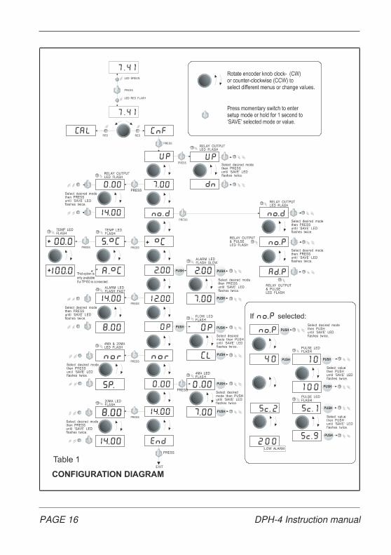
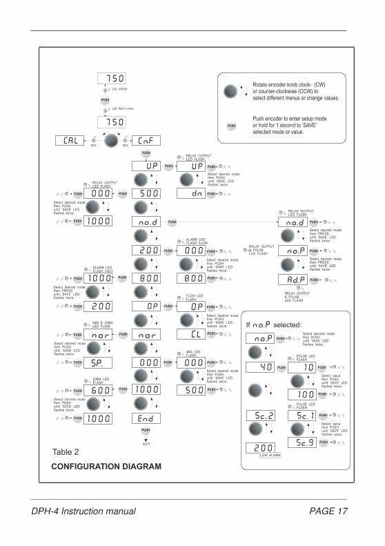
Table 1 (pH) and Table 2 (mV) is an overall diagram of all the variables
that can be changed in configuration. The LCD display shows a mode or
value and the appropriate LED lights up to show the position presently
showing. Pushing the encoder prepares to change this value. This is
indicated by the LED flashing. To save a change push until the yellow
“SAVE” LED flashes twice. The change is now saved in non-volatile
memory and will be used by the DPH-4.
This manual from now on will say:
Pushing the encoder: ‘PUSH’
Pushing the encoder until the save LED flashes twice: ‘SAVE’
Clockwise direction of the encoder knob: Rotate ‘CW’
Counter-clockwise direction of the encoder knob: Rotate ‘CCW’’
Either direction of the encoder: “Rotate’
F To change large numbers quickly rotate the encoder in a “flicking” manner.
Dosing mode is selected for up [UP] or down [dn].
Setpoint is selected between 0.00 to 14.00pH or 000 to 1000mV
Next select the relay output mode. There are three options.
Normal dosing [no.d], Normal Proportional dosing [no.P] and
Adaptive Proportional dosing [Ad.P]
(pH only) Temperature compensation is selected manually in +oC mode.
‘PUSH’ and dial up the new temperature. Range is 0 to 100oC.
Connecting a TP150 temperature electrode enables the DPH-4 to use
automatic compensation. Select SoC for manual or AoC for auto com-
pensation. In AoC mode the actual temperature is displayed.
Exit without saving by rotating the encoder (Temp LED goes off) and then
‘PUSH’. Press ‘SAVE to accept automatic compensation.
PAGE 14 DPH-4 Instruction manual

F Automatic temp. compensation is not available if no temp. electrode is connected.
The next menu sets low and high alarm. The alarm LED flashes slowly
when dialling low alarm, fast when dialling high alarm. Low alarm range
is from 0.00pH (000mV) to high alarm. High alarm range is from low alarm
to 14.00pH. (1000mV)
F A flashing LED indicates that a value can be modified in this position.
Flow switch configuration mode is selected for normally open [OP] or
normally closed. [CL]
4-20mA output is configured for normal [nor] or setpoint [SP.] operation.
The pH / mV for 4mA and 20mA are selected in the next configuration. First
the 4mA LED flashes to allow entering and ‘SAVE’ pH / mV for 4mA. Repeat
this procedure for 20mA. 4mA range is from 0.00pH (000mV) to pH7.00
(500mV). 20mA range is from pH8.00 (600mV) to pH14.00 (1000 mV).
Only the 20mA slope is entered in mA Setpoint. Range for the mA slope
is 0.5 to 5.00pH (50 to 500 mV). 4mA always is setpoint. It is important to
note that dosing mode [UP, dn] is properly selected if SP. mode is used.
If additional changes are necessary rotate ‘CW’ or ‘CCW’ to return to
any of the above mentioned options. Only a single configuration change
can be made if necessary. There is no need to configure from beginning
to end.
F A single configuration change can be made if necessary. There is no need
to configure from beginning to end.
When all configurations are done step to the next menu [End] to exit.
‘PUSH’ returns to operating mode. The DPH-4 always returns to operating
mode after 2 minutes if left in configuration or calibration mode.
F The DPH-4 automatically returns to ‘RUN’ after 2 minutes if left anywhere
in the configuration or calibration menu.
To only change the setpoint push and hold down the encoder until the
green LED flashes and the present setpoint is displayed. Release and dial
a new setpoint. Push again until the SAVE LED flashes two times.
DPH-4 Instruction manual PAGE 15
PAGE 16 DPH-4 Instruction manual
DPH-4 Instruction manual PAGE 17
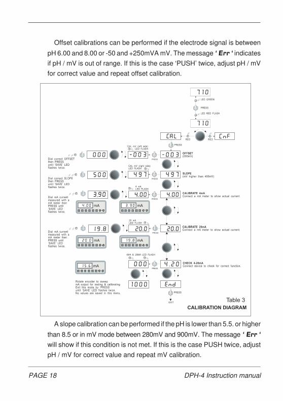
Offset calibrations can be performed if the electrode signal is between
pH 6.00 and 8.00 or -50 and +250mVA mV. The message ‘ Err ‘ indicates
if pH / mV is out of range. If this is the case ‘PUSH’ twice, adjust pH / mV
for correct value and repeat offset calibration.
A slope calibration can be performed if the pH is lower than 5.5. or higher
than 8.5 or in mV mode between 280mV and 900mV. The message ‘ Err ‘
will show if this condition is not met. If this is the case PUSH twice, adjust
pH / mV for correct value and repeat mV calibration.
PAGE 18 DPH-4 Instruction manual

OPERATION
Initial check of the DPH-4.
After the instrument is properly installed, an electrode or simulator
connected and the power applied, the “RUN” LED will light up. The output
relay may latch depending on the signal input. Sweeping across the range
with a simulator will activate the relay and “RELAY OUTPUT” LED at the
programmed setpoint.
Calibrating the DPH-4 with a simulator.
The operator should be familiar with the different effects if OFFSET and
SLOPE calibrations are carried out. Offset adjustments increase or de-
crease the reading regardless of the absolute measured value. pH7 is a
prefixed iso-potential and increasing the slope always moves the reading
away from pH7. Readings below pH7 therefore decrease in the displayed
value. Readings above pH7 increase in the displayed value. (Fig.6)
OFFSET calibrations should be carried out first, however offset and
slope calibrations can be performed separately and need not be done
consecutively.
Set the simulator to pH 7.00
‘PUSH’ and ‘Rotate CCW’ to go to CAL. ‘PUSH’ turns on the offset LED.
‘PUSH’ again, the offset LED now flashes and the display shows “live” pH
FIG. 5 THE DIFFERENT EFFECTS OF OFFSET AND SLOPE.
DPH-4 Instruction manual PAGE 19
input. ‘Rotate’ until 7.00 shows on the display and ‘SAVE’. Offset is now
calibrated.
An offset calibration can only be performed if the pH is between 6.00
and 8.00. The display shows Err if a value outside these parameters is
present. ‘PUSH’ two times, the display shows “live” pH to allow the
operator to correct for a valid offset pH value. ‘PUSH’ now returns to the
offset calibration menu to repeat the procedure.
Rotate ‘CCW’ goes to End then ‘PUSH’ to exit. Rotate ‘CW’ proceeds
to the slope calibration.
SLOPE calibration.
Set the simulator lower than pH 5.50 or higher than pH 8.50
‘PUSH’ turns on the slope LED. ‘PUSH’ again, the slope LED now
flashes and the display shows “live” pH input. ‘Rotate’ until the correct
slope value shows on the display and ‘SAVE’. Slope is now calibrated.
An accurate slope calibration can only be performed if the pH is lower
than 5.50 or higher than 8.50 The display shows Err if a value inside these
parameters is present. ‘PUSH’ two times, the display then shows “live”
pH to allow the operator to correct for a valid pH value. ‘PUSH’ now returns
to the slope calibration menu to repeat the procedure.
Rotate ‘CCW’ two times goes to End then ‘PUSH’ to exit. Rotate ‘CW’
proceeds to mA calibrations. (See 4-20mA output)
Redox electrodes
Contrary to pH electrodes, redox (metal electrodes) do not exhibit
changes in slope or zero point. Nevertheless one may occasionally
experience wrong redox measurements, most frequently the cause being
a contaminated electrode. Cleaning and/or regeneration of the electrode
will cure the problem. It is very unusual to get wrong readings with redox
electrodes when using redox buffer solutions. The use of redox buffers
therefore is restricted to a simple function test of a redox electrode.
The mV offset and mV slope calibration modes of the DPH-4 are mainly
used to correct minor instrument offset or gain errors of the input section.
PAGE 20 DPH-4 Instruction manual

mV offset calibrations should be carried out first, however mV offset
and mV gain calibrations can be performed separately and need not be
done consecutively.
Set the simulator to read 000mV (no signal output).
‘PUSH’ and ‘Rotate CCW’ to go to CAL. ‘PUSH’ turns on the OFFSET
(left side) LED. ‘PUSH’ again, the LED now flashes and the display shows
“live” mV input. ‘Rotate’ until 000 shows on the display and ‘SAVE’. mV
offset is now calibrated.
Rotate ‘CCW’ goes to End then ‘PUSH’ to exit. Rotate ‘CW’ proceeds
to the mV CAL (gain) calibration.
A mV gain calibration can only be performed with more than 280mV
input. The display shows Err if a value outside these parameters is
present. If this happens ‘PUSH’ two times, the display shows “live” mV to
allow the operator to correct for a valid mV offset value. ‘PRESS’ now
returns to the calibration menu to repeat the procedure.
F Set the simulator mV output higher than 280mV.
‘PUSH’ turns on the SLOPE (right side) LED. ‘PUSH’ again, the LED
now flashes and the display shows “live” mV input. ‘Rotate’ until the correct
mV value shows on the display and ‘SAVE’. The mV reading of the DPH-4
is now accurate.
Rotate ‘CCW’ two times goes to End then ‘PUSH’ to exit. Rotate ‘CW’
proceeds to mA calibrations. (See 4-20mA output)
Selecting Mode of Operation.
Dosing
Adding chemicals such as chlorine or bromine to water increases the
reading. The DPH-4 has to stop the pump or valve at the entered setpoint.
The reading of the water to be treated therefore is below the desired value,
(selected SET POINT) therefore dosing is set to UP.
In a situation where the reading of the water is reduced, the water to be
treated is above the desired value, (selected SET POINT) therefore
dosing is set to down.
DPH-4 Instruction manual PAGE 21
Setpoint
Once the input signal reaches setpoint the output relay switches off. A
dead band of 0.15pH (15mV) is used in normal mode. The relay output
switches on again at 0.15pH (15mV) above/below setpoint. (depending
on UP/dn mode)
Dosing mode
In normal dosing mode [no.d] the output relay simply switches on and
off below or above the setpoint. (depending on UP/dn mode)
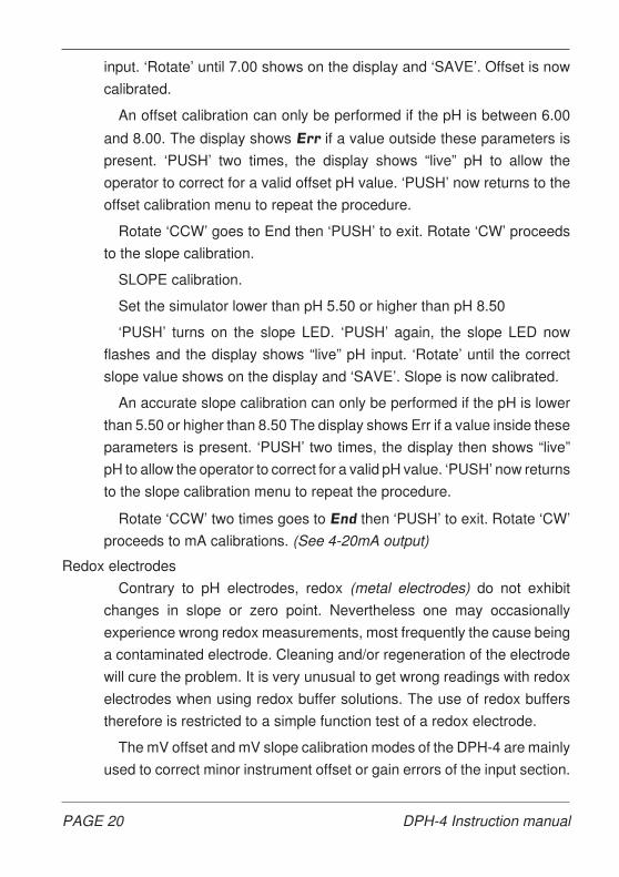
In normal Proportional mode [no.P] the relay output starts to pulse on
and off once the input mV moves toward the setpoint. The difference of
input signal versus setpoint is controlled by the amount of “gradient” set
in the configuration program.
The lowest setting of 10 starts the output relay pulsing if 3.00pH (240
mV) below/above setpoint. The on/off ratio gradually reduces until the
relay switches off at setpoint.
Setting the gradient to the maximum of 100 starts the output relay
pulsing when 0.5pH (10 mV) below/above setpoint giving a very steep
gradient. The on/off ratio reduces very rapidly. (See Fig.6) for ‘gradient’
versus pulse output.
FIG. 6 Normal Proportional Dosing.
PAGE 22 DPH-4 Instruction manual

Depending on the application and pumps or valves used a shorter or
longer minimum pulse is desirable. The minimum pulse length is selected
in the next window (Sc.2) Pulse width is from 1 to 9 seconds.
In Adaptive Proportional mode [Ad.P] the relay output is controlled
through a complex algorithm that continuously monitors the difference
between actual mV and set point. The output starts to pulse and varies
the ON/OFF cycle as the mV-input approaches the set point value. The
ON/OFF cycle however is also adjusted from a ‘correction factor’, which
in turn is governed by the history of a previous dosing cycle. This makes
for a fully dynamic
dosing control, which
adapts for widely
varying conditions in
a cooling tower or
other plant installa-
tions. Dosing for an
excessive period of
time without a corre-
sponding movement
in mV is recognized
as a possible failure.
The output begins to pulse, preventing overdosing.
The pulse output exhibits a very wide duty cycle. The ON and OFF times
are both dynamic, varying from 1.5 to 30 seconds.
Up or down mode is possible with Adaptive Proportional dosing.
The time taken for the DPH-4 to register the neutralising effect of the
chemicals injected depends on the mixing and retention time of the plant
installation. The distance between the injection point of neutralising agent
and the electrode greatly affects the quantity released into the system.
Therefore which dosing mode to use largely depends on an installation
and can possibly only be determined on site after some initial running of
the plant.
FIG. 7 Adaptive Proportional Dosing.
DPH-4 Instruction manual PAGE 23
Alarm
A second relay with potential free contacts controlled through config-
ured low and high alarm mV points can be connected to an alarm device
or use the potential free relay contacts for event monitoring or recording
digital data into a central processor system. The relay can be used as a
second setpoint control output.
Flow-switch
A flow-switch connected to the DPH-4 prevents dosing chemicals if for
any reason the water flow has stopped. Two types of flow-switches exist:
The term “normally open” is used if the contacts are open with flow and
close if flow stops. Select OP mode if this type of switch is used.
The term “normally closed” is used if the contacts are closed with flow
and open if flow stops. Select CL mode for this type of switch.
If it is not certain what type of switch is in the system operate the DPH-4
and configure for OP or CL until normal operation of the relay output is
established with water flowing. If no water flows through the system the
DPH-4 prevents the relay from switching and flashes the green LED.
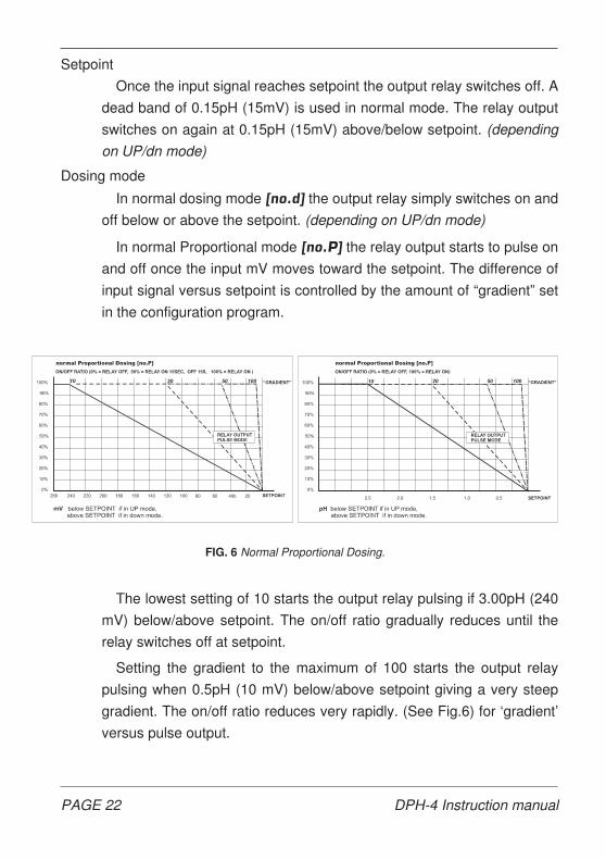
4-20mA signal output.
The DPH-4 features two modes of operation for the 4-20mA signal
output. In normal operation [nor] a “window” is configured by selecting a
low mV for 4mA and a high mV for 20mA current. The 4mA point is
selected between 000 and 500 mV. The 20mA point is selected between
600 and 1000 mV.
FIG. 8 4-20mA normal Signal current control.
PAGE 24 DPH-4 Instruction manual

This shows that mV can be traced over the entire 1000mV range or as
little as 100 mV. (See Fig.8)
Choosing setpoint control [SP.] fixes the 4mA to the programmed
setpoint. The signal current increases as the actual mV moves away from
the setpoint. In UP mode the signal current increases as the mV falls below
the setpoint. In dn mode the signal current increases as the mV rises
above the setpoint. (See Fig.9)
The amount of current increase versus mV is governed by the pro-
grammed slope that can be selected from 50 to 500mV. ( Do not confuse
the term “slope here with the slope calibration of mV).
Example:
Mode is UP, setpoint is 650 m and mA slope is set at 200 mV.
Signal current output is 20mA as long as the mV is below 450 mV, starts
to decrease as the mV moves to 950 at which point signal current is 4mA.
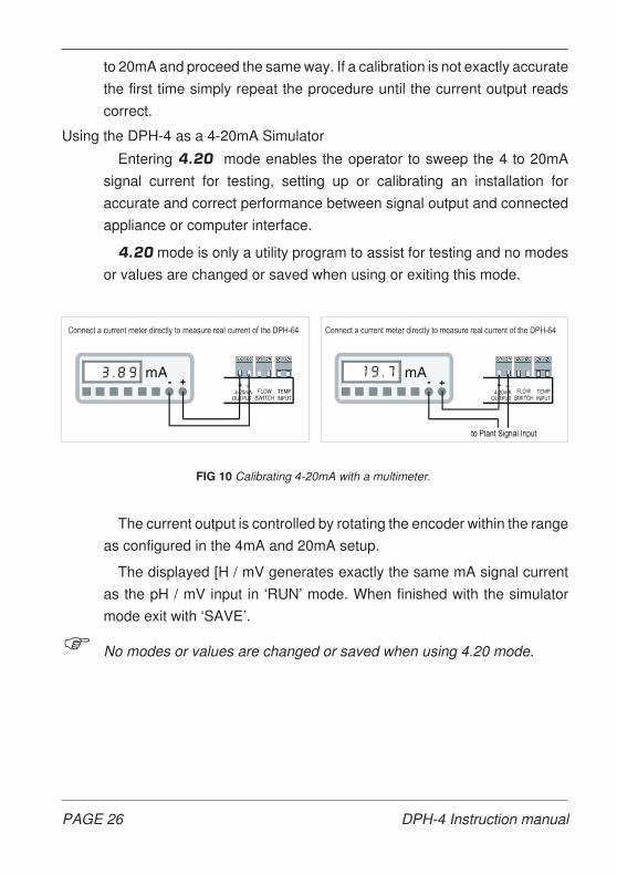
Calibrating 4mA and 20mA with a multimeter.
A real current calibration is carried out by connecting a multi meter
across the terminals (no termination resistor is required) to measure the
mA current.
The meter can also be connected in series in an already existing
installation. (See Fig.10)
Enter calibration [CAL] and ‘Rotate’ until the 4mA LED lights up. ‘PUSH’
to enter 4mA calibration. The display shows 4.00. Dial the measured mA
with ‘Rotate’. ‘SAVE’ and the actual current is corrected to 4.00mA. Move
FIG. 9 4-20mA Setpoint Signal current control.
DPH-4 Instruction manual PAGE 25
to 20mA and proceed the same way. If a calibration is not exactly accurate
the first time simply repeat the procedure until the current output reads
correct.
Using the DPH-4 as a 4-20mA Simulator
Entering 4.20 mode enables the operator to sweep the 4 to 20mA
signal current for testing, setting up or calibrating an installation for
accurate and correct performance between signal output and connected
appliance or computer interface.
4.20 mode is only a utility program to assist for testing and no modes
or values are changed or saved when using or exiting this mode.
The current output is controlled by rotating the encoder within the range
as configured in the 4mA and 20mA setup.
The displayed [H / mV generates exactly the same mA signal current
as the pH / mV input in ‘RUN’ mode. When finished with the simulator
mode exit with ‘SAVE’.
F No modes or values are changed or saved when using 4.20 mode.
FIG 10 Calibrating 4-20mA with a multimeter.
PAGE 26 DPH-4 Instruction manual
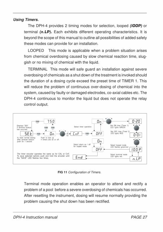
Using Timers.
The DPH-4 provides 2 timing modes for selection, looped (lOOP) or
terminal (n.LP). Each exhibits different operating characteristics. It is
beyond the scope of this manual to outline all possibilities of added safety
these modes can provide for an installation.
LOOPED This mode is applicable when a problem situation arises
from chemical overdosing caused by slow chemical reaction time, slug-
gish or no mixing of chemical with the liquid.
TERMINAL This mode will safe guard an installation against severe
overdosing of chemicals as a shut down of the treatment is invoked should
the duration of a dosing cycle exceed the preset time of TIMER 1. This
will reduce the problem of continuous over-dosing of chemical into the
system, caused by faulty or damaged electrodes, co-axial cables etc. The
DPH-4 continuous to monitor the liquid but does not operate the relay
control output.
Terminal mode operation enables an operator to attend and rectify a
problem of a pool before a severe overdosing of chemicals has occurred.
After resetting the instrument, dosing will resume normally providing the
problem causing the shut down has been rectified.
FIG 11 Configuration of Timers.
DPH-4 Instruction manual PAGE 27

WARRANTY
We, HOFMANN ELECTRONICS, guarantee this unit against de-
fects due to faulty manufacture or breakdown of components for a
period of twelve month from the date of purchase, subject to the following
provisions:
° The guarantee will cover original failure of parts and natural
defects due to manufacturing causes. Otherwise repair
charges are to be to the owners cost.
° The warranty does not cover any carriage costs.
The warranty is void if:
° The instrument is damaged due to rough handling or transport
after purchase.
° The article has not been used in accordance with the operating
instructions.
° Any parts in the instrument have been changed or have been
altered in any way.
° The serial number is removed or defaced.
All other warranties and conditions, express or implied, are void.
° DPH-4 SERIAL No.
Due to a continuing effort to improve the product the manufacturer
reserves the right to change or alter the product without notices.
PAGE 28 DPH-4 Instruction manual