
Pharos Installation Guide - pharoscontrols.com · 5 LPC INSTALLATION The Pharos Lighting Playback...
36
Copyright 2004-9 Pharos Architectural Controls Limited. All rights reserved. © INSTALLATION GUIDE & HARDWARE REFERENCE
-
Upload
trinhduong -
Category
Documents
-
view
239 -
download
1
Transcript of Pharos Installation Guide - pharoscontrols.com · 5 LPC INSTALLATION The Pharos Lighting Playback...

Copyright 2004-9 Pharos Architectural Controls Limited. All rights reserved.©
INSTALLATION GUIDE& HARDWARE REFERENCE

2
CONTENTS
Contents............................................................................................................. 2Welcome.............................................................................................................4
Overview............................................................................................4Software installation........................................................................ 4Quicktime.......................................................................................... 4Sample media.....................................................................................4
LPC installation & hardware reference........................................................ 5LPC installation.................................................................................5LPC layout..........................................................................................5LPC versions......................................................................................5Power supply & grounding............................................................. 6Realtime clock battery.................................................................... 7Compact flash card.......................................................................... 7Status LEDs & error codes............................................................ 8Reset switch & watchdog...............................................................8Ports....................................................................................................9
EXP installation & hardware reference......................................................11LPC connection & disconnection...............................................11RS485................................................................................................12DMX-IN...........................................................................................12DALI-M.............................................................................................13DALI-S.............................................................................................. 13LTC....................................................................................................14AUDIO............................................................................................. 14
AVC installation & hardware reference.....................................................15AVC installation..............................................................................15AVC layout.......................................................................................15Power supply & grounding........................................................... 16Realtime clock battery.................................................................. 17Compact flash card........................................................................17Status LEDs & error codes..........................................................18Reset switch & watchdog.............................................................18Video systems.................................................................................19Ports..................................................................................................19
RIO installation & hardware reference......................................................21RIO installation...............................................................................21RIO layout........................................................................................21RIO versions................................................................................... 21Power supply................................................................................... 22Status LEDs & error codes..........................................................22Address wheel................................................................................ 22Reset switch & watchdog.............................................................23Ports..................................................................................................23
3
BPS installation & hardware reference...................................................... 25BPS installation............................................................................... 25BPS versions....................................................................................25BPS layout........................................................................................ 26
Learning IR receiver.......................................................................27PoE installation & hardware reference...................................................... 29
PoE installation............................................................................... 29PoE layout........................................................................................ 29Power supply................................................................................... 29Power supply choice & loading................................................... 30Grounding........................................................................................30Status LEDs..................................................................................... 30
RDM installation & hardware reference....................................................31RDM installation............................................................................ 31RDM layout..................................................................................... 31Power supply................................................................................... 31Grounding........................................................................................32Status LEDs..................................................................................... 32DMX Thru termination................................................................ 32DMX & RDM guidelines...............................................................32
Warranty & compliance information..........................................................36
Power supply................................................................................... 26Status LEDs..................................................................................... 26Address wheel................................................................................ 27Reset switch & watchdog.............................................................27

4
WELCOME
Thank you for purchasing a Pharos Architectural Controls product, we hope that it fulfills your expectations and provides a lifetime of reliable service.
If you have any questions or require technical support please contact:
Email: [email protected]: +44-(0)20-7471-9229
Technical specifications of this and other Pharos products can be found on our website at http://www.pharoscontrols.com.
OVERVIEW
The Pharos control solution has two complementary parts: the installed Controllers (LPC, AVC) and Remote Devices (RIO), and the Designer software which runs on any personal computer and is only required when creating or modifying the presentation.
This guide is primarily intended as a reference for the Pharos hardware installation. For Designer software help please refer to the on-line documentation (once installed, see below) or the PDF file on the installation CD.
SOFTWARE INSTALLATION
• Microsoft Windows 2000, XP & Vista:
Insert the CD and use Windows Explorer to navigate to the Pharos Designer folder and double-click on the file “pharos_designer_installer.exe” to launch the software installation process and follow the simple instructions.
• Apple Macintosh OS-X (10.4.x):
Insert the CD and use Finder to navigate to the Pharos Designer folder and double-click on the file “pharos_designer_installer.dmg” to launch the software installation process and follow the simple instructions.
QUICKTIME
Apple’s Quicktime must be installed for Designer to function and so version 7 is supplied on the CD; navigate to the Apple Quicktime folder and double-click either “QuickTimeInstaller.exe” (Windows) or “QuickTimeInstaller.dmg” (Macintosh) to launch the installation process.
SAMPLE MEDIA
Sample media has been kindly provided by Projected Image Digital, Digigobos and Mode Studios which you are free to use without paying a royalty fee. These media clips can be found in the Sample Media folder on the CD and more can be obtained by visiting these suppliers’ websites; click on the links provided on the Media pane of the Designer software.

5
LPC INSTALLATION
The Pharos Lighting Playback Controllers (LPC) are designed to be permanently installed in a central control room/cupboard or DIN consumer unit for remote deployment. The enclosure and mounting complies with DIN43880 and EN60715 (35/7.5 rail) respectively.
The units are 100% solid state and have been qualified to operate in a dry environment within a temperature range of 0°C to 50°C (32°F to 122°F). Sealed IP65 rated consumer units are available for outdoor use, please consult your Pharos distributor or representative.
Since the units require no user intervention once installed they are suitable for remote installation with all configuration and management taking place over an Ethernet network. However it is recommended that access can be gained in the unlikely event of a hardware failure.
LPC LAYOUT
The following drawing illustrates the layout of the Pharos Lighting Playback Controller, refer to the following sections for details:
LPC VERSIONS
There are two versions of the LPC available: LPC 1 and LPC 2 (shown above). The LPC 1 supports only one universe of DMX (512 channels) and the LPC 2 supports two universes (1024 channels). Both can be used as a stand-alone controller or co-operatively, via an Ethernet network, to form a scalable system.
RS232 SERIAL PORT MIDI INPUT & OUTPUT DMX512 OUTPUTS (2)
DIGITAL INPUTS (8) ETHERNET(PoE)
DC INPUT(9-48V)
USB
RESET
STATUSLEDS
LPC

6
POWER SUPPLY
The LPC can be powered in two different ways:
• DC power (9 to 48V)
A limited power source approved to UL60950-1 CAN/CSA C22.2 No. 60950-1.03 MUST be used, with an output voltage of 9 to 48V DC.
Such a power supply can be connected directly to the LPC using the DC Input connector. The pins on this connector are marked:
Positive input (9 to 48V DC)Signal ground (0V)
Chassis ground (earth)
The power supply should be connected to the Positive and Signal ground inputs, ensuring the polarity is correct. Where possible, use a 12V (minimum) supply in preference to a 9V supply to ensure some headroom.
The LPC with two optional Expansion Modules will typically consume 5W.
• Power-over-Ethernet (PoE)
A standard (802.3af) Power-over-Ethernet switch may be used to provide both power and a network connection to the LPC using a single cable.
The LPC operates as a PoE Class 0 device (0.44>12.95W) and will typically consume 5W with two optional Expansion Modules.
GROUNDING
The LPC is designed to be mounted on a grounded (earthed) DIN-rail and a dedicated Chassis ground (earth) terminal is also provided which should be connected to a suitable earth.
Additionally, the Signal ground must be tied to Chassis ground to provide a suitable reference:
• DC power
Typically, the power supply’s output will be isolated (floating) and so a connection must be made between Signal and Chassis ground (earth) which in turn should be connected to a suitable earth as noted above (see diagram).
CAUTION: Power should only be applied using one of the above methods. Redundant operation using both sources is not supported.
CAUTION: Power must not be disconnected when uploading project data nor during bootloader/firmware updates to the LPC as corruption of the data or software may occur, perhaps even rendering the unit inoperable.
LPC

• Power-over-Ethernet (PoE)
As the 802.3af specification does not provide a ground connection a connection must be made between Signal and Chassis ground (earth) to a suitable earth (see diagram).
If in any doubt at all, or if you have unusual power supply or grounding/earthing requirements, then please consult Pharos support.
EXPANSION MODULES
ETHERNET
10/100TX PD
9 - 48V DC
PoE
EXPANSION MODULES
ETHERNET
10/100TX PD
9 - 48V DC
+ 0
REALTIME CLOCK BATTERY
The LPC’s internal realtime clock is battery-backed to ensure operation when the unit is not powered. The battery should last for at least 10 years and is easily replaced when necessary, replacement battery: Renata CR2032 Lithium Button Cell.
COMPACT FLASH CARD
The LPC is shipped with a 256Mbyte Type I Compact Flash Card which should be sufficient for most projects since the LPC’s data storage is extremely efficient, even with a multitude of imported media files. However, a larger capacity card could of course be fitted if required.
As only the project’s programming data resides on the card, the card is also a convenient way to back-up data for archiving; the Pharos Designer project file for example.
Furthermore, in the event of LPC hardware failure, simply moving the card into a replacement unit is sufficient to get the project up and running again.
CAUTION: Risk of explosion if battery replaced by incorrect type. Dispose of used batteries according to the manufacturer’s instructions.
ATTENTION: Il y a un danger d’explosion s’il y a un remplacement incorrect de batterie. Mettre au rebut les batteries usages conformement aux instructions du fabricant.
7
DC power: Power-over-Ethernet:
LPC
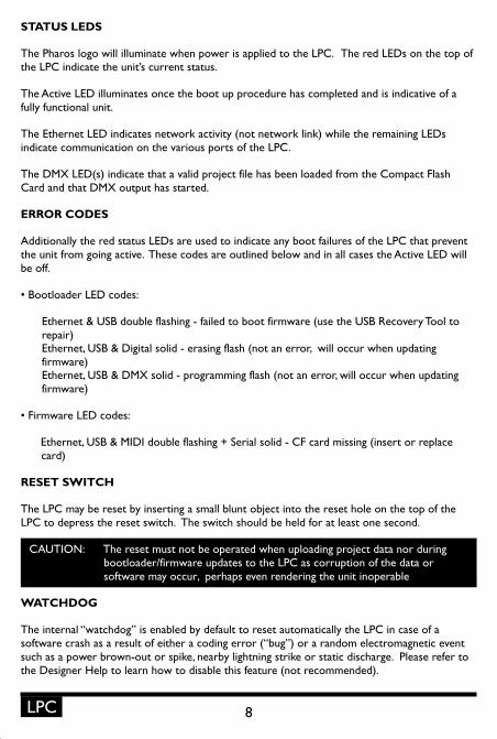
STATUS LEDS
The Pharos logo will illuminate when power is applied to the LPC. The red LEDs on the top of the LPC indicate the unit’s current status.
The Active LED illuminates once the boot up procedure has completed and is indicative of a fully functional unit.
The Ethernet LED indicates network activity (not network link) while the remaining LEDs indicate communication on the various ports of the LPC.
The DMX LED(s) indicate that a valid project file has been loaded from the Compact Flash Card and that DMX output has started.
ERROR CODES
Additionally the red status LEDs are used to indicate any boot failures of the LPC that prevent the unit from going active. These codes are outlined below and in all cases the Active LED will be off.
• Bootloader LED codes:
Ethernet & USB double flashing - failed to boot firmware (use the USB Recovery Tool to repair)Ethernet, USB & Digital solid - erasing flash (not an error, will occur when updating firmware)Ethernet, USB & DMX solid - programming flash (not an error, will occur when updating firmware)
• Firmware LED codes:
Ethernet, USB & MIDI double flashing + Serial solid - CF card missing (insert or replace card)
RESET SWITCH
The LPC may be reset by inserting a small blunt object into the reset hole on the top of the LPC to depress the reset switch. The switch should be held for at least one second.
WATCHDOG
The internal “watchdog” is enabled by default to reset automatically the LPC in case of a software crash as a result of either a coding error (“bug”) or a random electromagnetic event such as a power brown-out or spike, nearby lightning strike or static discharge. Please refer to the Designer Help to learn how to disable this feature (not recommended).
CAUTION: The reset must not be operated when uploading project data nor during bootloader/firmware updates to the LPC as corruption of the data or software may occur, perhaps even rendering the unit inoperable
8LPC
9
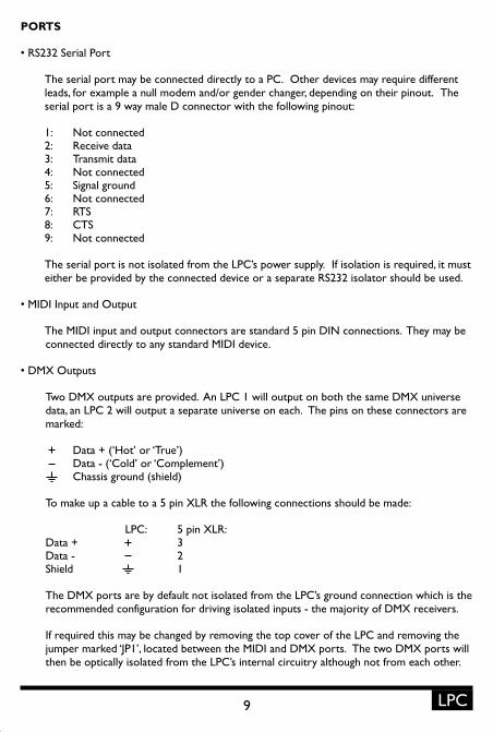
PORTS
• RS232 Serial Port
The serial port may be connected directly to a PC. Other devices may require different leads, for example a null modem and/or gender changer, depending on their pinout. The serial port is a 9 way male D connector with the following pinout:
1: Not connected2: Receive data3: Transmit data4: Not connected5: Signal ground6: Not connected7: RTS8: CTS9: Not connected
The serial port is not isolated from the LPC’s power supply. If isolation is required, it must either be provided by the connected device or a separate RS232 isolator should be used.
• MIDI Input and Output
The MIDI input and output connectors are standard 5 pin DIN connections. They may be connected directly to any standard MIDI device.
• DMX Outputs
Two DMX outputs are provided. An LPC 1 will output on both the same DMX universe data, an LPC 2 will output a separate universe on each. The pins on these connectors are marked:
Data + (‘Hot’ or ‘True’)Data - (‘Cold’ or ‘Complement’)Chassis ground (shield)
To make up a cable to a 5 pin XLR the following connections should be made:
LPC: 5 pin XLR:Data + 3Data - 2Shield 1
The DMX ports are by default not isolated from the LPC’s ground connection which is the recommended configuration for driving isolated inputs - the majority of DMX receivers.
If required this may be changed by removing the top cover of the LPC and removing the jumper marked ‘JP1’, located between the MIDI and DMX ports. The two DMX ports will then be optically isolated from the LPC’s internal circuitry although not from each other.
LPC

10
• Digital Inputs
The LPC features 8 digital inputs on the 16 way connector, the terminals marked ‘C’ are all connected to a common ground.
The LPC inputs can individually operate in one of two modes:
Contact closure: An external volt-free switch may be connected between the desired input pin (marked ‘1’ to ‘8’) and a common pin (marked ‘C’). When the connection is made the input is forced low.
An internal pull-up resistor to 5V via a 1.5Kohm resistor ensures that each input maintains a high when left open. The contact closure device must therefore be rated at 5V, 3mA or higher.
Digital input: An external voltage source (such as a 12V trigger output) may be connected between the desired input pin and a common pin.
The triggering device must drive the line to below 0.8V to guarantee a low and to above 4.2V to guarantee a high.
Note that in some cases, triggering devices may not actively drive the trigger voltage to a low state. In this case it will be necessary to use a relay to interface between the triggering device’s output voltage and the LPC’s input in contact closure mode. This technique may also be used when individual isolation of each digital input is required.
In either mode, the maximum rated input voltage is 48V. The inputs should never be driven with a higher voltage nor a negative voltage as damage may occur.
The digital inputs are optically isolated from the LPC’s internal circuitry but not from each other.
• Ethernet
A standard 10/100TX Ethernet connection may be made to the LPC. As the LPC supports Power-over-Ethernet (PoE), a PoE switch or midspan injector can be used.
• USB
The USB port may be used to connect the LPC to a PC to upload project data and update the LPC’s internal operating software.
The USB connection may be connected and disconnected while the LPC is powered provided the LPC has a good ground connection. If unsure, or if using Power-over-Ethernet without a ground connection (not recommended), then the LPC should be powered down before connecting or disconnecting USB.
LPC

EXPANSION MODULES
The LPC is equipped with an Expansion port for the connection of Pharos Expansion Modules (EXP) which provide a range of additional interfaces and functionality.
A single LPC can support up to two Expansion Modules of any type, see below. Expansion Modules are powered directly from the LPC so no additional power connection is required.
• Connecting the Expansion Module(s):
1: Disconnect power to the LPC.2: Position the Expansion Module next to the LPC so that the connectors align.3: Push the Expansion Module and LPC together so that the ends are flush.4: Connect the second Expansion Module if required.5: Reconnect power and the Expansion Module(s) will automatically be discovered.
When using two Expansion Modules of different types it does not matter which Module is connected directly to the LPC (Port 1) and which Module is connected to the first Module (Port 2). However, when using two Modules of the same type, they are distinguished by their position (Port 1 or 2).
The red Active LED common to all Modules will illuminate when it has been successfully detected by the LPC. The other status LEDs differ by Module type, see next section.
• Disconnecting or replacing the Expansion Module(s):
1: Disconnect power to the LPC.2: Gently pull the LPC and Expansion Module apart.3: Connect a replacement or alternative Expansion Module if required.4: Reconnect power, the changes will automatically be discovered.
Refer to the Designer Help for Expansion Module configuration (if any) and usage.
CAUTION: The LPC’s Expansion port is for the exclusive use of Pharos Expansion Modules. Connecting any other device to this port may damage either the LPC, the other device or both.
Likewise, the Pharos Expansion Modules can only be used with a Pharos LPC. Connecting to any other device may damage either the Expansion Module, the other device or both.
11 EXP
12
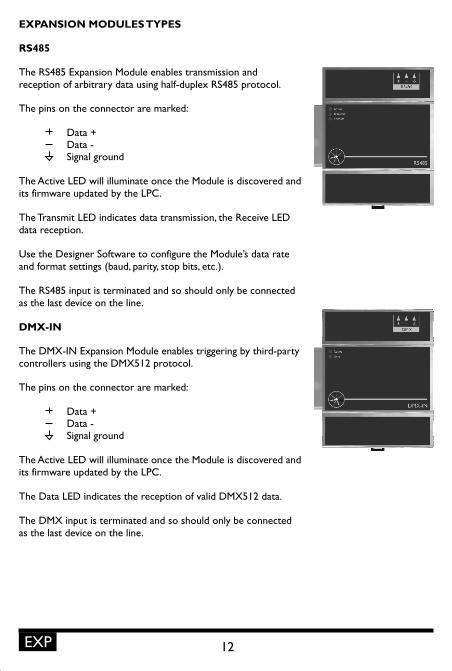
EXPANSION MODULES TYPES
RS485
The RS485 Expansion Module enables transmission and reception of arbitrary data using half-duplex RS485 protocol.
The pins on the connector are marked:
Data +Data -Signal ground
The Active LED will illuminate once the Module is discovered and its firmware updated by the LPC.
The Transmit LED indicates data transmission, the Receive LED data reception.
Use the Designer Software to configure the Module’s data rate and format settings (baud, parity, stop bits, etc.).
The RS485 input is terminated and so should only be connected as the last device on the line.
DMX-IN
The DMX-IN Expansion Module enables triggering by third-party controllers using the DMX512 protocol.
The pins on the connector are marked:
Data +Data -Signal ground
The Active LED will illuminate once the Module is discovered and its firmware updated by the LPC.
The Data LED indicates the reception of valid DMX512 data.
The DMX input is terminated and so should only be connected as the last device on the line.
EXP

DALI-M
The DALI-Master Expansion Module enables the control of up to 64 DALI fixtures/ballasts using the DALI protocol.
The pins on the connector are marked:
DALI bus (polarity insensitive)DALI bus (polarity insensitive)Chassis ground (for optional shield)
The Active LED will illuminate once the Module is discovered and its firmware updated by the LPC.
The Ready LED will illuminate once the Module is configured using the Designer Software.
The Data LED indicates the transmission of DALI data.
The Service LED, in conjunction with the recessed Service switch, is used during the configuration and physical addressing of the DALI network.
DALI-S
The DALI-Slave Expansion Module enables triggering by third-party controllers using the DALI protocol.
The pins on the connector are marked:
DALI bus (polarity insensitive)DALI bus (polarity insensitive)Chassis ground (for optional shield)
The Active LED will illuminate once the Module is discovered and its firmware updated by the LPC.
The Ready LED will illuminate once the Module is configured using the Designer Software.
The Data LED indicates the reception of DALI data.
The Service LED, in conjunction with the recessed Service switch, is used during the configuration and physical addressing of the DALI network.
13 EXP
14
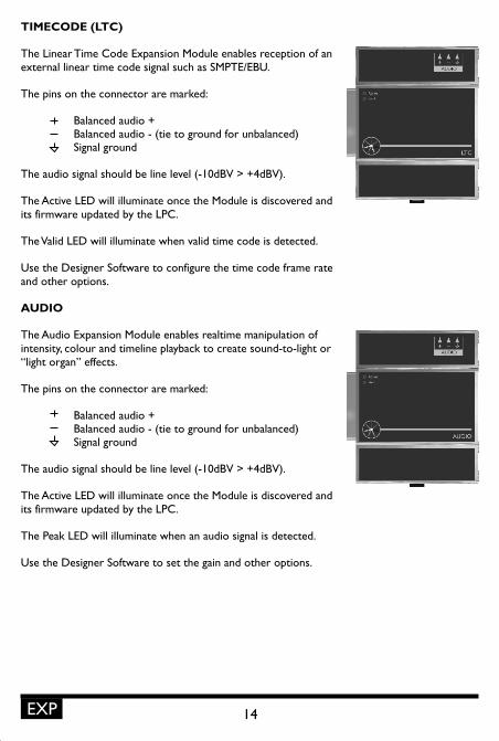
TIMECODE (LTC)
The Linear Time Code Expansion Module enables reception of an external linear time code signal such as SMPTE/EBU.
The pins on the connector are marked:
Balanced audio +Balanced audio - (tie to ground for unbalanced)Signal ground
The audio signal should be line level (-10dBV > +4dBV).
The Active LED will illuminate once the Module is discovered and its firmware updated by the LPC.
The Valid LED will illuminate when valid time code is detected.
Use the Designer Software to configure the time code frame rate and other options.
AUDIO
The Audio Expansion Module enables realtime manipulation of intensity, colour and timeline playback to create sound-to-light or “light organ” effects.
The pins on the connector are marked:
Balanced audio +Balanced audio - (tie to ground for unbalanced)Signal ground
The audio signal should be line level (-10dBV > +4dBV).
The Active LED will illuminate once the Module is discovered and its firmware updated by the LPC.
The Peak LED will illuminate when an audio signal is detected.
Use the Designer Software to set the gain and other options.
EXP

15
AVC INSTALLATION
The Pharos Audio Visual Controller (AVC) is designed to be permanently installed in a central control room/cupboard or DIN consumer unit for remote deployment. The enclosure and mounting complies with DIN43880 and EN60715 (35/7.5 rail) respectively.
The unit is 100% solid state and has been qualified to operate in a dry environment within a temperature range of 0°C to 50°C (32°F to 122°F). Sealed IP65 rated consumer units are available for outdoor use, please consult your Pharos distributor or representative.
Since the unit requires no user intervention once installed it is suitable for remote installation with all configuration and management taking place over an Ethernet network. However it is recommended that access can be gained in the unlikely event of a hardware failure.
AVC LAYOUT
The following drawing illustrates the layout of the Pharos Audio Visual Controller, refer to the following sections for details:
AVC
AUDIO/VIDEO OUTPUTS RS232/485SERIAL PORT
AUDIO/VIDEO INPUTS
ETHERNET(PoE)
DC INPUT(9-48V)
USB
RESET
STATUSLEDS

16
POWER SUPPLY
The AVC can be powered in two different ways:
• DC power (9 to 48V)
A limited power source approved to UL60950-1 CAN/CSA C22.2 No. 60950-1.03 MUST be used, with an output voltage of 9 to 48V DC.
Such a power supply can be connected directly to the AVC using the DC Input connector. The pins on this connector are marked:
Positive input (9 to 48V DC)Signal ground (0V)
Chassis ground (earth)
The power supply should be connected to the Positive and Signal ground inputs, ensuring the polarity is correct. Where possible, use a 12V (minimum) supply in preference to a 9V supply to ensure some headroom.
The AVC will typically consume 7W.
• Power-over-Ethernet (PoE)
A standard (802.3af) Power-over-Ethernet switch may be used to provide both power and a network connection to the AVC using a single cable.
The AVC operates as a PoE Class 0 device (0.44>12.95W) and will typically consume 7W.
GROUNDING
The AVC is designed to be mounted on a grounded (earthed) DIN-rail and a dedicated Chassis ground (earth) terminal is also provided which should be connected to a suitable earth.
Additionally, the Signal ground must be tied to Chassis ground to provide a suitable reference:
• DC power
Typically, the power supply’s output will be isolated (floating) and so a connection must be made between Signal and Chassis ground (earth) which in turn should be connected to a suitable earth as noted above (see diagram).
CAUTION: Power should only be applied using one of the above methods. Redundant operation using both sources is not supported.
CAUTION: Power must not be disconnected when uploading project data nor during bootloader/firmware updates to the AVC as corruption of the data or software may occur, perhaps even rendering the unit inoperable.
AVC

• Power-over-Ethernet (PoE)
As the 802.3af specification does not provide a ground connection a connection must be made between Signal and Chassis ground (earth) to a suitable earth (see diagram).
If in any doubt at all, or if you have unusual power supply or grounding/earthing requirements, then please consult Pharos support.
COMPACT FLASH CARD
ETHERNET
10/100TX PD
9 - 48V DC
PoE
COMPACT FLASH CARD
ETHERNET
10/100TX PD
9 - 48V DC
+ 0
REALTIME CLOCK BATTERY
The AVC’s internal realtime clock is battery-backed to ensure operation when the unit is not powered. The battery should last for at least 10 years and is easily replaced when necessary, replacement battery: Renata CR2032 Lithium Button Cell.
COMPACT FLASH CARD
The AVC is shipped with a 2Gbyte Type I Compact Flash Card.
The duration of video content that can be stored on a card will vary depending on the MPEG2 bitrate used to encode it. For a 2GB card capacity could be anything from 30 to 90 minutes. However, a larger capacity card could of course be fitted if required.
As only the project’s programming data resides on the card, the card is also a convenient way to back-up data for archiving; the Pharos Designer project file for example.
Furthermore, in the event of AVC hardware failure, simply moving the card into a replacement unit is sufficient to get the project up and running again.
CAUTION: Risk of explosion if battery replaced by incorrect type. Dispose of used batteries according to the manufacturer’s instructions.
ATTENTION: Il y a un danger d’explosion s’il y a un remplacement incorrect de batterie. Mettre au rebut les batteries usages conformement aux instructions du fabricant.
DC power: Power-over-Ethernet:
17 AVC
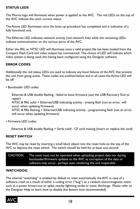
STATUS LEDS
The Pharos logo will illuminate when power is applied to the AVC. The red LEDs on the top of the AVC indicate the unit’s current status.
The Active LED illuminates once the boot up procedure has completed and is indicative of a fully functional unit.
The Ethernet LED indicates network activity (not network link) while the remaining LEDs indicate communication on the various ports of the AVC.
Either the PAL or NTSC LED will illuminate once a valid project file has been loaded from the Compact Flash Card and video output has commenced. The choice of LED will indicate which video system is being used, this having been configured using the Designer software.
ERROR CODES
Additionally the red status LEDs are used to indicate any boot failures of the AVC that prevent the unit from going active. These codes are outlined below and in all cases the Active LED will be off.
• Bootloader LED codes:
Ethernet & USB double flashing - failed to boot firmware (use the USB Recovery Tool to repair)NTSC & PAL solid + Ethernet/USB indicating activity - erasing flash (not an error, will occur when updating firmware)NTSC & PAL flashing + Ethernet/USB indicating activity - programming flash (not an error, will occur when updating firmware)
• Firmware LED codes:
Ethernet & USB double flashing + Serial solid - CF card missing (insert or replace the card)
RESET SWITCH
The AVC may be reset by inserting a small blunt object into the reset hole on the top of the AVC to depress the reset switch. The switch should be held for at least one second.
WATCHDOG
The internal “watchdog” is enabled by default to reset automatically the AVC in case of a software crash as a result of either a coding error (“bug”) or a random electromagnetic event such as a power brown-out or spike, nearby lightning strike or static discharge. Please refer to the Designer Help to learn how to disable this feature (not recommended).
CAUTION: The reset must not be operated when uploading project data nor during bootloader/firmware updates to the AVC as corruption of the data or software may occur, perhaps even rendering the unit inoperable
18AVC

19 AVC
VIDEO SYSTEMS
The AVC supports either the NTSC (525/60) or video systems and this configuration is done using the Designer software and is uploaded as part of the project file.
Video coding: MPEG-2 MP@ML/SP@ML VBR/CBRCoded frame rate: 29.97fps (525/60, interlaced)
25fps (625/50, interlaced)Display frame rate: 29.97fps (525/60, interlaced)
25fps (625/50, interlaced)MPEG-2 resolution: 720x480 & 704x480 (525/60)
720x576 & 704x576 (625/50)MPEG-2 GOP max: 36fields/18frames (525/60), 30/15 recommended
30fields/15frames (625/50), 24/12 recommendedAspect ratio: 4:3 or 16:9 anamorphic
PORTS
• Video Output
Video output is via three BNC connectors. These connectors can be configured using Designer to output either Composite (CV), S-Video (Y, C) or Component (Y, Pr, Pb).
The video output is taken from the output of an internal video mixer, the inputs to which are the encoded video (uploaded using Designer) and the video input.
• Analog Audio Output
Balanced stereo audio output is provided @ 0dBV line level on a 6 way connector:
Balanced audio right channel +Balanced audio right channel - (tie to ground for unbalanced)Signal ground
Balanced audio left channel +Balanced audio left channel - (tie to ground for unbalanced)Signal ground
The analog audio output is taken from the output of an internal audio mixer, the inputs to which are the encoded stereo audio (uploaded using Designer) and the analog audio input.
• Digital Audio Output
Digital multi-channel audio output is provided on the S/PDIF BNC connector.
The digital audio output is taken directly from a compatible audio bit-stream (uploaded using Designer) such as Linear PCM, Dolby Digital AC-3 or MPEG-2 audio.
• Video Input
Video input is via two BNC connectors. These connectors can be configured using Designer to accept either Composite (CV) or S-Video (Y, C).
PAL (625/50)
L
R
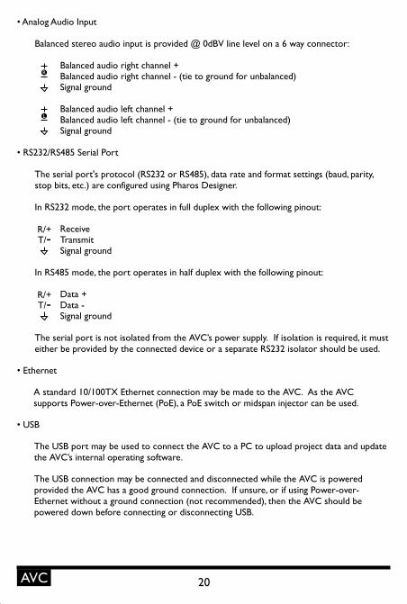
• Analog Audio Input
Balanced stereo audio input is provided @ 0dBV line level on a 6 way connector:
Balanced audio right channel +Balanced audio right channel - (tie to ground for unbalanced)Signal ground
Balanced audio left channel +Balanced audio left channel - (tie to ground for unbalanced)Signal ground
• RS232/RS485 Serial Port
The serial port's protocol (RS232 or RS485), data rate and format settings (baud, parity, stop bits, etc.) are configured using Pharos Designer.
In RS232 mode, the port operates in full duplex with the following pinout:
Receive Transmit Signal ground
In RS485 mode, the port operates in half duplex with the following pinout:
Data + Data - Signal ground
The serial port is not isolated from the AVC’s power supply. If isolation is required, it must either be provided by the connected device or a separate RS232 isolator should be used.
• Ethernet
A standard 10/100TX Ethernet connection may be made to the AVC. As the AVC supports Power-over-Ethernet (PoE), a PoE switch or midspan injector can be used.
• USB
The USB port may be used to connect the AVC to a PC to upload project data and update the AVC’s internal operating software.
The USB connection may be connected and disconnected while the AVC is powered provided the AVC has a good ground connection. If unsure, or if using Power-over-Ethernet without a ground connection (not recommended), then the AVC should be powered down before connecting or disconnecting USB.
20AVC
R/+T/-
R/+T/-
L
R

21 RIO
RIO INSTALLATION
The Pharos Remote Input/Output Devices (RIO) are ancillary devices that provide additional input and output interfaces to a Pharos system. As such, they can not be used on their own but must have at least one Pharos LPC or AVC present on an Ethernet network to function.
The units are designed to be permanently installed in a control room/cupboard or DIN consumer unit. The enclosure and mounting complies with DIN43880 and EN60715 (35/7.5 rail) respectively.
The units are 100% solid state and have been qualified to operate in a dry environment within a temperature range of 0°C to 50°C (32°F to 122°F). Sealed IP65 rated consumer units are available for outdoor use, please consult your Pharos distributor or representative.
RIO LAYOUT
The following drawing illustrates the layout of a Pharos Remote Input/Output Device, refer to the following sections for details:
RIO VERSIONS
There are three versions of the RIO available:
RIO 80: 8 digital/analog inputs & RS232/485 serial port.RIO 44: 4 digital/analog inputs, 4 relay outputs & RS232/485 serial port (shown above).RIO 08: 8 relay outputs & RS232/485 serial port.
RS232/485SERIAL PORT
ETHERNET(PoE)INPUTS/OUTPUTS (4x)
INPUTS/OUTPUTS (4x)
RESET
ADDRESSWHEEL
STATUSLEDS
22RIO
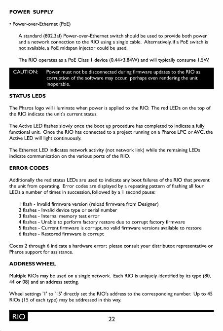
POWER SUPPLY
• Power-over-Ethernet (PoE)
A standard (802.3af) Power-over-Ethernet switch should be used to provide both power and a network connection to the RIO using a single cable. Alternatively, if a PoE switch is not available, a PoE midspan injector could be used.
The RIO operates as a PoE Class 1 device (0.44>3.84W) and will typically consume 1.5W.
STATUS LEDS
The Pharos logo will illuminate when power is applied to the RIO. The red LEDs on the top of the RIO indicate the unit's current status.
The Active LED flashes slowly once the boot up procedure has completed to indicate a fully functional unit. Once the RIO has connected to a project running on a Pharos LPC or AVC, the Active LED will light continuously.
The Ethernet LED indicates network activity (not network link) while the remaining LEDs indicate communication on the various ports of the RIO.
ERROR CODES
Additionally the red status LEDs are used to indicate any boot failures of the RIO that prevent the unit from operating. Error codes are displayed by a repeating pattern of flashing all four LEDs a number of times in succession, followed by a 1 second pause:
1 flash - Invalid firmware version (reload firmware from Designer)2 flashes - Invalid device type or serial number3 flashes - Internal memory test error4 flashes - Unable to perform factory restore due to corrupt factory firmware5 flashes - Current firmware is corrupt, no valid firmware versions available to restore6 flashes - Restored firmware is corrupt
Codes 2 through 6 indicate a hardware error; please consult your distributor, representative or Pharos support for assistance.
ADDRESS WHEEL
Multiple RIOs may be used on a single network. Each RIO is uniquely identified by its type (80, 44 or 08) and an address setting.
Wheel settings '1' to '15' directly set the RIO's address to the corresponding number. Up to 45 RIOs (15 of each type) may be addressed in this way.
CAUTION: Power must not be disconnected during firmware updates to the RIO as corruption of the software may occur, perhaps even rendering the unit inoperable.

23 RIO
For systems with more than 15 RIOs of a single type, the manual ('M') setting should be used to allow identification using the RIO's serial number rather than the address.
RESET SWITCH
The RIO may be reset by inserting a small blunt object into the reset hole on the top of the RIO to depress the reset switch. The switch should be held for at least one second.
WATCHDOG
An internal "watchdog" will automatically reset the RIO in case of a software crash as a result of either a coding error ("bug") or a random electromagnetic event such as a power brown-out orspike, nearby lightning strike or static discharge.
PORTS
• Digital/Analog Inputs (RIO 80 and RIO 44 only)
The RIO features 8 (RIO 80) or 4 (RIO 44) digital/analog inputs on two (RIO 80) or one (RIO 44) 8 way connectors. To connect an input signal to the RIO, one connection should be made to the desired input pin, marked '1' to '8' (RIO 80) or '1' to '4' (RIO 44), and the other should be made to the adjacent common pin.
The RIO inputs can be individually configured to operate in one of three modes:
Contact closure: An external volt-free switch may be connected between the input pin and the signal ground pin.
In this mode, the input pin is internally pulled-up to 5V via a 2.2Kohm resistor, so the switch only needs to be rated at 5V, 2.5mA or greater.
Digital input: An external voltage source (such as a 12V trigger output) may be connected between the input pin and the signal ground pin.
In this mode, the input pin is internally pulled down to 0V via a 2Mohm resistor and the maximum input voltage supported is 24V.
The RIO may be configured using Pharos Designer to specify what the 'high' and 'low' threshold voltages are. This facility can be used to provide 'schmitt trigger' action.
Analog input: An external voltage source (such as a 0-10V analog signal) may be connected between the input pin and the signal ground pin.
In this mode, the input pin is internally pulled down to 0V via a 2Mohm resistor and the maximum input voltage supported is 24V.
CAUTION: The reset must not be operated during firmware updates to the RIO as corruption of the software may occur, perhaps even rendering the unit inoperable.

24RIO
The RIO may be configured using Pharos Designer to specify what the input voltage range is. Voltages inside this range are reported as 0% to 100%.
In all modes, the maximum rated input voltage is 48V. The inputs should never be driven with a higher voltage nor negative voltage or damage may occur.
In all modes, all signal ground pins are connected together internally. This internal ground is isolated from the PoE power source and network, but shared with the serial port.
• Relay Outputs (RIO 08 and RIO 44 only)
The RIO features 8 (RIO 08) or 4 (RIO 44) relay outputs on two (RIO 08) or one (RIO 44) 8 way connectors.
The RIO relays are rated at 48V, 0.25A. This comparatively low rating is due to the use of solid-state relays to ensure silent operation and long-term reliability.
All relay outputs are fully isolated from each other and all other ports.
• RS232/RS485 Serial Port
The serial port's protocol (RS232 or RS485), data rate and format settings (baud, parity, stop bits, etc.) are configured using Pharos Designer.
In RS232 mode, the port operates in full duplex with the following pinout:
Receive Transmit Signal ground
In RS485 mode, the port operates in half duplex with the following pinout:
Data + Data - Signal ground
In either mode, the signal ground is isolated from the PoE power source and network, but shared with the digital/analog inputs (RIO 80 and RIO 44 only).
• Ethernet
A standard 10/100TX Ethernet connection must be made to the RIO. A Power-over-Ethernet (PoE) switch or midspan injector is required to operate the RIO.
R/+T/-
R/+T/-

25 BPS
BPS INSTALLATION
The Pharos Button Panel Stations (BPS) are ancillary devices that provide user interfaces to a Pharos system. As such, they can not be used on their own but must have at least one Pharos LPC or AVC present on an Ethernet network to function.
The units are designed to be permanently installed into standard, single-gang back boxes (not supplied). The units are 100% solid state and have been qualified to operate in a dry environment within a temperature range of 0°C to 50°C (32°F to 122°F).
The following drawing illustrates a typical installation (T1 UK shown):
BPS VERSIONS
There are four versions of the BPS available:
T1 UK: Slimline Aluminium bezel with magnetic overlay, UK single-gang size.T1 US:T2 UK: Two-part Acrylic bezel with user-printable inlay, UK single-gang size.T2 US: Two-part
Slimline Aluminium bezel with magnetic overlay, US single-gang size.
Acrylic bezel with user-printable inlay, US single-gang size.
BACK BOX: 35mm (1.5”) or deeper, remove or bend flat the top and bottom tabs if present
BEZEL & ELECTRONICS: Mounts flush to the wall, ensure that the back box cutout is not oversized

26BPS
BPS LAYOUT
The following drawing illustrates the layout of a Pharos Button Panel Station (T1 UK shown with overlay removed), refer to the following sections for details:
IR RECEIVER
RESET
ETHERNET(PoE)
ADDRESSWHEEL
STATUSLEDS
POWER SUPPLY
• Power-over-Ethernet (PoE)
A standard (802.3af) Power-over-Ethernet switch should be used to provide both power and a network connection to the BPS using a single cable. Alternatively, if a PoE switch is not available, a PoE midspan injector could be used.
The BPS operates as a PoE Class 1 device (0.44>3.84W) and will typically consume 1.5W.
STATUS LEDS
The LEDs on the rear of the unit provide the following status information:
Pwr: Power - illuminates when the unit is correctly powered.Act: Active - illuminates once the unit has successfully booted and is operational.Net: Network - illuminates when the unit is sending or receiving relevant Ethernet data.Lnk: Link - illuminates once the unit has established an Ethernet link.100: 100BASE-TX - illuminates when the Ethernet link is operating at 100Mbit/s.
CAUTION: Power must not be disconnected during firmware updates to the BPS as corruption of the software may occur, perhaps even rendering the unit inoperable.
27 BPS
ADDRESS WHEEL
Multiple BPSs may be used on a single network. Each BPS is uniquely identified by its address setting.
Wheel settings '1' to '15' directly set the BPS's address to the corresponding number. Up to 15 BPSs may be addressed in this way. For systems with more, the manual ('M') setting should be used to allow identification using the BPS's serial number rather than the address.
RESET SWITCH
The BPS may be reset by removing the magnetic overlay (T1) or the outer Acrylic bezel, keycaps & inlay (T2) and inserting a small blunt object into the reset hole centred between the top four buttons to depress the reset switch. The switch should be held for at least one second.
WATCHDOG
An internal "watchdog" will automatically reset the BPS in case of a software crash as a result of either a coding error ("bug") or a random electromagnetic event such as a power brown-out orspike, nearby lightning strike or static discharge.
LEARNING IR RECEIVER
The BPS may be taught to recognise up to 8 different IR codes from a standard infra red remote control. When a key on the remote control is pressed during normal operation, the BPS will react as though one of its 8 buttons has been pressed.
CAUTION: The reset must not be operated during firmware updates to the BPS as corruption of the software may occur, perhaps even rendering the unit inoperable.
To enter Learn Mode:
1. Enter by holding down the bottom two buttons while pressing and releasing reset.• The buttons will display a clockwise chase sequence.
2. Release the bottom two buttons. • Each button will flash quickly (4Hz) if an IR code has been learnt, or slowly (1Hz) if not.• No network communication will operate while in Learn Mode.• Learn Mode will automatically exit after 60 seconds of inactivity.
To learn an IR Code:
1. Briefly press and release a single button which should learn the IR code. • The button will start flashing rapidly (8Hz) and the other buttons will extinguish.
2. Within ten seconds, point the IR remote at the BPS and press and hold the desired key. • The buttons will display a clockwise chase sequence when the IR code has been learnt.
3. Release the key on the IR remote. • The button now will be flashing quickly to indicate that it has an IR code stored.

28BPS
To erase an IR code:
1. Press and hold for three seconds the button which should erase its IR code. • The buttons will display a clockwise chase sequence when the IR code has been erased.
2. Release the button. • The button will now be flashing slowly to indicate that it has no IR code stored.
To exit Learn Mode: 1. Press the reset button or wait for 60 seconds.
• The buttons will now revert to normal operation.• Network communication will resume.
Note that the BPS does not have to be part of a networked Pharos system to learn IR codes, all that is required is PoE power and the donor IR remote control.

29 PoE
PoE INSTALLATION
The Pharos 1+4port Power-over-Ethernet Switch (PoE) is designed to be permanently installed in a central control room/cupboard or DIN consumer unit for remote deployment. The enclosure and mounting complies with DIN43880 and EN60715 (35/7.5 rail) respectively.
The unit is 100% solid state and has been qualified to operate in a dry environment within a temperature range of 0°C to 50°C (32°F to 122°F). Sealed IP65 rated consumer units are available for outdoor use, please consult your Pharos distributor or representative.
PoE LAYOUT
The following drawing illustrates the layout of the Pharos PoE Switch, refer to the following sections for details:
POWER SUPPLY
• DC power (48V)
A limited power source approved to UL60950-1 CAN/CSA C22.2 No. 60950-1.03 MUST be used, with an output voltage of 48V DC.
Such a power supply can be connected directly to the PoE using the DC Input connector. The pins on this connector are marked:
Positive input (48V DC)Signal ground (0V)
Chassis ground (earth)
STATUSLEDS
ETHERNETINPUT
ETHERNET (PoE) OUTPUTS (4)
DC INPUT(48V)

30PoE
The power supply should be connected to the Positive and Signal ground inputs, ensuring the polarity is correct.
POWER SUPPLY CHOICE & PoE LOADING
The choice of power supply, in terms of its power rating, depends on the intended loading of the four PoE ports.
If the intention is to supply four Class 1 devices (for example RIO or BPS) then a 24W (48V @0.5A) supply will suffice.
If, however, the intention is to supply four Class 0 devices (for example LPC or AVC) then a 96W (48V @2A) supply will be required.
Multiple PoEs may be powered by a single power supply provided its rating is increased accordingly.
STATUS LEDS
The Pharos logo will illuminate when power is applied to the PoE. The red LEDs on the top of the PoE indicate the unit's status:
Active: Indicates that the unit is functional.Ethernet: Illuminates when the link has been established and toggles off to indicate data.Port 1-4:PoE: Indicates that one or more of the ports is supplying PoE power.Error: Flashes to indicate an error condition.
GROUNDING
The PoE is designed to be mounted on a grounded (earthed) DIN-rail and a dedicated Chassis ground (earth) terminal is also provided which should be connected to a suitable earth.
Illuminates when the link has been established and toggles off to indicate data.

31 RDM
RDM INSTALLATION
The Pharos 1+4port DMX512 Repeater (RDM) is designed to be permanently installed in a central control room/cupboard or DIN consumer unit for remote deployment. The enclosure and mounting complies with DIN43880 and EN60715 (35/7.5 rail) respectively.
The unit is 100% solid state and has been qualified to operate in a dry environment within a temperature range of 0°C to 50°C (32°F to 122°F). Sealed IP65 rated consumer units are available for outdoor use, please consult your Pharos distributor or representative.
RDM LAYOUT
The following drawing illustrates the layout of the Pharos DMX Repeater, refer to the following sections for details:
POWER SUPPLY
• DC power (9-48V)
A limited power source approved to UL60950-1 CAN/CSA C22.2 No. 60950-1.03 MUST be used, with an output voltage of 9 to 48V DC.
Such a power supply can be connected directly to the RDM using the DC Input connector. The pins on this connector are marked:
Positive input (9 to 48V DC)Signal ground (0V)
Chassis ground (earth)
STATUSLEDS
DMX INPUT & THRU(OPTO-ISOLATED)
DMX OUTPUTS (4)
DC INPUT(9-48V)

32RDM
The power supply should be connected to the Positive and Signal ground inputs, ensuring the polarity is correct.
The RDM will typically consume 4W with all ports fully loaded.
GROUNDING
STATUS LEDS
The Pharos logo will illuminate when power is applied to the RDM. The red LEDs on the top of the RDM indicate the unit's status:
Active: Indicates that the unit is functional.DMX data: Illuminates when DMX data is being routed (input to all ports).RDM data: Illuminates when RDM data is being routed (a port to input).Error: Flashes to indicate an error condition.
DMX THRU TERMINATION
If the DMX Thru connection is not being used to daisy-chain to other DMX devices then the supplied termination resistor MUST be fitted to ensure data integrity.
DMX & RDM GUIDELINES
The RDM is compatible with the DMX512, DMX512(1990), DMX512-A and RDM 1.0 standards and care should be taken to ensure that your cabling, wiring topology and termination also complies with these standards.
Such compliance is beyond the scope of this document but a good resource is "Recommended Practice in DMX 512" by Adam Bennette which is available through PLASA and USITT.
The RDM is designed to be mounted on a grounded (earthed) DIN-rail and a dedicated Chassis ground (earth) terminal is also provided which should be connected to a suitable earth.

33

34

35

WARRANTY
This Pharos Architectural Controls (“Pharos”) product is warranted for the period of five (5) years from the original date of purchase against defective materials and workmanship.
In the event that warranty service is required, you should contact your dealer or Pharos technical support at the following email address: [email protected].
CONDITIONS
1. The warranty is only valid if the Pharos Designer software registration is fully and properly completed, and Pharos is presented with the original invoice or sales confirmation, and the serial number on the product has not been defaced.
2. Pharos’ obligations are limited to the repair or, at its discretion, replacement of the product or the defective part.
3. It is the consumer’s obligation to notify Pharos within one week of any suspected defect, and to return the goods prepaid to Pharos’ authorised service address. Goods will only be received under warranty when they are returned with a recognised RMA number that has been issued by Pharos.
4. Warranty repairs must be carried out by a nominated Pharos employee or Pharos approved service technician. No reimbursement will be made for repairs carried out by non-Pharos personnel or dealers, and any such repair work or damage to the product caused by such repair work will not be covered by this warranty.
5. This product is not considered to be defective in materials or workmanship by reason that it requires adaptation in order to conform to national or local technical or safety standards in force in any country other than the one for which the product was originally designed or manufactured. This warranty will not cover, and no reimbursement will be made for such adaptation or any damage which may result.
6. This warranty covers none of the following:
a) Maintenance and repair or replacement of parts due to normal wear and tear.
b) Cost relating to transport, removal or installation of the product.
c) Misuse, including the failure to use this product for its normal purposes or incorrect installation.
d) Damage caused by lightning, water, fire, acts of God, war, public disturbances, incorrect supply voltage, improper ventilation or any other cause beyond the control of Pharos.
7. This warranty is valid for any person who legally acquired possession of the product during the warranty period.
8. The consumer’s statutory rights in any applicable national legislation arising from the purchase are not affected by this warranty. The rights under this warranty are the consumer’s sole rights and Pharos, its subsidiaries or distributors shall not be liable for any indirect or consequential loss, damages for any loss of use, time, profits or income, or any damage to related equipment, materials or consumable parts.
COMPLIANCE
The Pharos Lighting Playback Controllers, Expansion Modules, Audio Visual Controller, Remote Input/Output Devices, Button Panel Stations & RDM/PoE Accessories are manufactured to the highest quality in compliance with the following international standards:
ENCLOSURE & MOUNTING
• EN60715: Top hat section (TH) 35-7.5mm & 35-15mm DIN rail.• DIN 43 880: Built-in equipment for electrical installations; Frame size 1.• IP40 rated.
ELECTROMAGNETIC COMPATIBILITY
• 2004/108/EEC (EMC)
SAFETY
• UL 60950-1:2002 & CAN/CSA C22.2 No. 60950-1-03.
ENVIRONMENTAL
• 2002/95/EC (RoHS)• 2002/96/EC (WEEE)
• 73/23/EEC (LVD)
CONFORMS TO ANSI/UL 60950-1CERTIFIED TO CAN/CSA-C22.2 60950-1
3097276
Rev. 3.0 LPC/EXP/AVC/RIO/BPS/PoE/RDM Hardware Reference - ETL/cETL - 24/03/2009


![Pharos Manual[1].pdf](https://static.fdocuments.us/doc/165x107/577cc34f1a28aba711959d3c/pharos-manual1pdf.jpg)