PEXa PLUMBING DESIGN AND INSTALLATION GUIDE · Plumbing Code, governed by the International...
34
PEXa PLUMBING DESIGN AND INSTALLATION GUIDE RAUPEX ® UV Shield Pipe and EVERLOC+ ® Compression-sleeve Fittings
Transcript of PEXa PLUMBING DESIGN AND INSTALLATION GUIDE · Plumbing Code, governed by the International...

PEXa PLUMBING DESIGN AND INSTALLATION GUIDERAUPEX® UV Shield Pipe and EVERLOC+® Compression-sleeve Fittings
1. Scope 3
2. System Overview 4 2.1 Application 4 2.2StandardsandCertifications 4 2.3Specification 5 2.4Warranty 5 2.5DesignServices 5
3. RAUPEX PEXa Pipe 6 3.1 Pipe Properties 6 3.2PipeDimensionsandWeights 6 3.3PipeMarkings 7 3.4PressureandTemperatureRatings 7 3.5ExcessiveTemperatureandPressureCapability 7 3.6CorrosionResistance 8 3.7ChlorineResistance 8 3.8UltravioletResistance 8 3.9BendRadius 9 3.10ChemicalCompatibility 9 3.11FreezeBreakResistance 9 3.12 Condensation 9 3.13 Pressure Loss 9
4. EVERLOC+ Compression-sleeve Fittings 10 4.1FittingScope 10 4.2FittingAssembly 12 4.3 Installation Considerations 12 4.4EVERLOC+Compression-sleeveTools 15
CONTENTS
Forupdatestothispublicationandthemostcurrenttechnicalinstructions,safetyinformationandmanufacturer’srecommendations,visitwww.na.rehau.com/resourcecenter
5. Design Considerations 17 5.1PipeSizing 17 5.2EquivalentLengthofFittings 18 5.3PipingLayouts 19 5.4ThermalExpansionandContraction 20 5.5InstallationinFire-ratedAssemblies 22 5.6OverheadInstallations 25 5.7WaterQuality 25 5.8HotWaterRecirculation 26 5.9WaterHammer 26
6. Installation Considerations 27 6.1LocalCodeApprovals 27 6.2Packaging,Transport,HandlingandStorage 27 6.3UncoilingPipe 27 6.4BendingPipe 27 6.5DistanceBetweenFittings 28 6.6PipeProtection 28 6.7Insulation 29 6.8InstallationBelow-grade,in-slab 29 6.9FixtureConnectionCommonComponents 29 6.10WaterHeaterConnections 30 6.11SupportingRAUPEXPipe 30 6.12SupportingEVERLOC+Fittings 31 6.13CopperSoldering 31 6.14KinkRepair 32 6.15ThawingFrozenPipe 32 6.16Disinfection 32 6.17PressureTesting 33
2
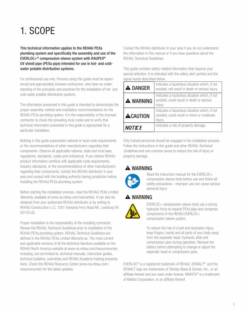
This technical information applies to the REHAU PEXa plumbing system and specifically the assembly and use of the EVERLOC+® compression-sleeve system with RAUPEX® UV shield pipe (PEXa pipe) intended for use in hot- and cold-water potable distribution systems.
Forprofessionaluseonly.Personsusingthisguidemustbeexperi-encedandappropriatelylicensedcontractors,whohaveanunder-standingoftheprinciplesandpracticesfortheinstallationofhot-andcold-waterpotabledistributionsystems.
TheinformationpresentedinthisguideisintendedtodemonstratetheproperassemblymethodandinstallationrecommendationsfortheREHAUPEXaplumbingsystem.Itistheresponsibilityofthelicensedcontractortochecktheprevailinglocalcodesandtoverifythattechnicalinformationpresentedinthisguideisappropriateforaparticular installation.
Nothinginthisguidesupersedesnationalorlocalcoderequirementsortherecommendationsofothermanufacturersregardingtheircomponents.Observeallapplicablenational,stateandlocallaws,regulations,standards,codesandordinances.IfyoubelieveREHAUproductinformationconflictswithapplicablecoderequirements,industrystandards,ortherecommendationsofothermanufacturersregardingtheircomponents,contacttheREHAUdistributorinyourareaandconsultwiththebuildingauthorityhavingjurisdictionbeforeinstallingtheREHAUPEXaplumbingsystem.
Beforestartingtheinstallationprocess,readtheREHAUPEXa Limited Warranty,availableatwww.na.rehau.com/warranties.ItcanalsobeobtainedfromyourauthorizedREHAUdistributororbywritingtoREHAUConstructionLLC,1501EdwardsFerryRoadNE,LeesburgVA20176US.
Properinstallationistheresponsibilityoftheinstallingcontractor.ReviewtheREHAUTechnical GuidelinespriortoinstallationoftheREHAUPEXaplumbingsystem.REHAUTechnical Guidelines are definedintheREHAUPEXa Limited Warranty as:ThemostcurrentandapplicableversionsofallthetechnicalliteratureavailableontheREHAUNorthAmericawebsiteatwww.na.rehau.com/resourcecenter,including,butnotlimitedto,technicalmanuals,instructionguides,technicalbulletins,submittalsandREHAUAcademytrainingpresenta-tions.ChecktheREHAUResourceCenter(www.na.rehau.com/resourcecenter)forthelatestupdates.
ContacttheREHAUdistributorinyourareaifyoudonotunderstandtheinformationinthismanualorifyouhavequestionsabouttheREHAUTechnical Guidelines.
Thisguidecontainssafety-relatedinformationthatrequiresyourspecialattention.Itisindicatedwiththesafetyalertsymbolandthesignalwordsdescribedbelow:
DANGERIndicatesahazardoussituationwhich,ifnotavoided,willresultindeathorseriousinjury.
WARNINGIndicatesahazardoussituationwhich,ifnotavoided,couldresultindeathorseriousinjury.
CAUTIONIndicatesahazardoussituationwhich,ifnotavoided,couldresultinminorormoderateinjury.
NOTICE Indicatesariskofpropertydamage.
Onlytrainedpersonnelshouldbeengagedintheinstallationprocess.FollowtheinstructionsinthisguideandotherREHAUTechnical Guidelinesandusecommonsensetoreducetheriskofinjuryorpropertydamage.
WARNINGReadtheinstructionmanualfortheEVERLOC+compression-sleevetoolsbeforeuseandfollowallsafetyprecautions-improperusecancauseseriouspersonalinjury
WARNINGEVERLOC+compression-sleevetoolsuseastronghydraulicforcetoexpandPEXapipeandcompresscomponentsoftheREHAUEVERLOC+compression-sleevesystem.
Toreducetheriskofcrushandlacerationinjury,keepfingers,handsandallpartsofyourbodyawayfromtheexpanderhead,hydraulicslideandcompressionjawsduringoperation.Removethebatterybeforeattemptingtochangeoradjusttheexpanderheadorcompressionjaws.
EVERLOC®isaregisteredtrademarkofREHAU.DEWALT® andtheDEWALTlogoaretrademarksofStanleyBlack&Decker,Inc.,oranaffiliatethereofandareusedunderlicense.MAKITA®isatrademarkofMakitaCorporation,oranaffiliatethereof.
1. SCOPE
3

2.1 ApplicationTheREHAUPEXaplumbingsystemincludesRAUPEXUVshieldPEXapipe,PEXacompressionsleevesandEVERLOC+polymerandlead-freebrassfittings.Thissystemisdesignedforpotableapplications.
TheEVERLOC+compression-sleevefittingsystemisacold-expan-sionPEXafittingsystemthatisavailableinpolymerandlead-free(LF)brassandisassembledwithaspeciallydesignedPEXacompressionsleeve.ThefittingisdesignedspecificallyforusewithRAUPEXpipeandcanonlybeassembledwiththeEVERLOC+compression-sleevetools.
Fig. 2.1: RAUPEX UV shield crosslinked polyethylene (PEXa) pipe
Fig. 2.2: EVERLOC+ compression-sleeve fittings and sleeves
2. SYSTEM OVERVIEW
Fig. 2.3: EVERLOC+ compression-sleeve tools
2.2 Standards and CertificationsThegoverningmodelcodeswithintheUnitedStatesandCanadadefinetherequiredstandardsforPEXpipingsystems.
IntheUS,themodelcodesthataretypicallyadoptedbylocaljurisdictionsare:theInternationalCodes(Mechanical,PlumbingandResidential)governedbytheInternationalCodeCouncil(ICC)ortheUniformCodes(MechanicalandPlumbing)andtheNationalStandardPlumbingCode,governedbytheInternationalAssociationofPlumbingandMechanicalOfficials(IAPMO).
InCanada,themodelcodethatistypicallyadoptedbylocaljurisdic-tionsistheNationalPlumbingCodeofCanada(NPCC)whichisgovernedbytheNationalResearchCouncilofCanada(NRCC).
Withinthesemodelcodes,thestandardrequirementsforPEXpipeandfittingsareASTMF877orCSAB137.5.ThesestandardsdefinetherequirementsandtestmethodsforPEXpipingsystems.
TheREHAUPEXaplumbingsystemisthird-partycertifiedbyNSFInternational(www.nsf.org)tothefollowingstandards:-ASTMF876StandardSpecificationforCrosslinkedPolyethylene(PEX)Tubing-ASTMF877StandardSpecificationforCrosslinkedPolyethylene(PEX)Hot-andCold-WaterDistributionSystems-CSAB137.5CrosslinkedPolyethylene(PEX)TubingSystemsfor
Pressure Applications-NSF/ANSI14PlasticPipingSystemComponentsandRelated
Materials-NSF/ANSI61DrinkingWaterSystemComponentsandRelated
Materials-NSF/ANSI372DrinkingWaterSystemComponents–LeadContent(complieswiththelead-freerequirementsoftheU.S.SafeDrinkingWater Act)
4

2.3 SpecificationREHAUprovidesarecommendedspecificationfordomesticwaterpipingandfittings.Thisrecommendedspecificationisprovidedasaguidefordevelopmentofthefinalspecificationbyaarchitect,engineer,orbuilder.Thearchitect/engineer/buildershallberespon-sibletoconvertthisrecommendedspecificationintoafinalspecifica-tionthatmeetsthefunctionalneedsoftheclient,aswellastocomplywithallapplicablebuilding,plumbing,andmechanicalcodes.Specificationsareavailableatwww.na.rehau.com/resourcecenter.
2.4 WarrantyRAUPEXUVshieldpipeandEVERLOC+compression-sleevefittingsandsleevesarebackedbya25-yearlimitedwarranty.EVERLOC+compression-sleevetoolsarebackedbya2-yearlimitedwarranty.REHAUoffersthiswarrantywhentheinstallationiscarriedoutinaccordancewiththerequirementsoutlinedintheREHAUPEXa Warranty 855.018,whichisavailableasaseparatedocumentatwww.na.rehau.com/warranties.Pleasereadwarrantypriortoinstallation.
2.5 Design ServicesREHAUDesignServicescanprovidecustomerswithadetailedsubmittalpackagetosupporttheinstallationoftheREHAUPEXaplumbingsystem.
REHAUPlumbingDesignServicesinclude:-BIMlibraryofplumbingsystemcomponents-Productsubmittals-Projectbillofmaterials-Supportofpipelayoutbasedontheprojectengineer’sapprovedplumbingpipingdesign
2.5.1 Building Information Modeling LibraryTheREHAUBIMLibraryoffersadirectoryofdrawingsthatareeasytodownloadintoanactivedesign.BIMfilesofferefficienciestoprojectownersthrougheaseofcollaboration.TheREHAUBIMlibraryoffersmodelsofcoreproductsincludingpipe,fittings,manifoldsandinstallation accessories.
2.5.2 LoopCAD® SoftwareREHAUPlumbingCADcreatesprofessionalpipelayoutdrawingsandbillofmaterialsfortheREHAUPEXaplumbingsystem.
5

3. RAUPEX PEXa PIPE
3.1 Pipe PropertiesCrosslinkedpolyethyleneispolyethylene(PE)whichhasundergoneachangeinmolecularstructurewherebythepolymerchainsarechemicallylinked,crosslinked(X),witheachothertoformathree-dimensionalnetwork.Theresultisaflexiblethermosetpolymerwithimprovedmechanical,thermalandchemicalproperties.
TherearethreemethodsofmanufacturingPEX:-Theperoxidemethod(PEXa),ASTMrequiresaminimumof70%crosslinkedPEmolecules-Thesilanemethod(PEXb),ASTMrequiresaminimumof65%crosslinkedPEmolecules-Theradiationmethod(PEXc),ASTMrequiresaminimumof65%crosslinkedPEmolecules
RAUPEXpipeismanufacturedusingtheperoxidemethod(PEXa),whichyieldsthehighest,mostconsistentlevelofcrosslinking.PEXatechnologyenhancesflexibilityandthermalmemory,providingeaseofhandlingandkinkrepaircomparedtoPEXbandPEXc.
PEXahasdistinctadvantagesovermetalandotherpolymerpipes:-Resistspittingandstresscorrosion-Resistsscalinganddepositbuild-upwhenusedwithbothhardandsoftenedwater-Minimizesnoisethatistransmittedthroughpipes-Resistsnotchingandabrasiondamage
RAUPEXismanufacturedbyREHAUinafacilitywhosequalitymanagementsystemisISO9001certified.Inaddition,RAUPEXproductionisindependentlymonitoredannuallyNSFInternational,CSAInternationalandUnderwritersLaboratoriesInc.(UL).
Table 3.1: RAUPEX Properties
Specification English SI Standard
MinimumDensity
58lb/ft3 926kg/m3 ASTMF876
MinimumDegreeofCrosslinkling
70% 70% ASTMF876
MaxThermalConductivity
2.84Btuin/(ft2 ˚F•hr) 0.41W/(m˚K) DIN16892
CoefficientofLinear Expansion
9.33x10⁻⁴in/ft˚F@68˚F1.33x10-3in/ft˚F@212˚F
0.14mm/(m˚C)@20˚C0.2mm/(m˚C)@100˚C
Mean @ 20-70˚CperDIN16892
ModulusofElasticity
87,000-130,500psi@68˚F43,500-58,000psi@176˚F
600-900N/mm2 @20˚C300-400N/mm2 @80˚C
Minimum@20˚CperDIN16892
Specification English SI Standard
Tensile Strength
4194-4355psi@68˚F2610-2900psi@176˚FperASTMD638
26-30N/mm2 @20˚C18-20N/mm2 @80˚CperASTMD638
--
IZODImpactResistance
No Break No Break --
Roughness e=0.00028in. e=0.007mm --
TemperatureWorkingRange
-40to200˚F -40to93˚C --
MaximumShort-termExposure
150psig@210˚F(48hr)
1035kPa@99˚C(48hr)
ASTMF876
UVResistance SeeTB218 ASTM2657
3.2 Pipe Dimensions and WeightsRAUPEXpipeisavailableinnominalsizesrangingfrom3/8to2in.RAUPEXisinaccordancetothedimensionalstandardsdefinedinASTMF876.RAUPEXiscoppertubesize(CTS)outsidediameter(OD),whichmeansthattheactualODofthepipeis1/8in(3.18mm)largerthanthenominalsize.
Wallthicknessisdefinedbythestandarddimensionalratio(SDR).RAUPEXUVshieldpipeisSDR9,whichequatestotheoutsidediameterbeingapproximatelyninetimesthewallthickness.
Table 3.2: RAUPEX Dimensions and Weights
Pipe Size Average OD in (mm)
Min Wall Thicknessin (mm)
Weightlb/ft (kg/m)
3/8in 0.500(12.70) 0.070(1.78) 0.04(0.07)
1/2in 0.625(15.88) 0.070(1.78) 0.06(0.08)
5/8in 0.750(19.50) 0.083(2.12) 0.08(0.11)
3/4in 0.875(22.22) 0.097(2.47) 0.10(0.15)
1 in 1.125(28.58) 0.125(3.18) 0.17(0.26)
11/4in 1.375(34.92) 0.153(3.88) 0.25(0.37)
11/2in 1.625(41.28) 0.181(4.59) 0.35(0.52)
2 in 2.125(53.98) 0.236(6.00) 0.60(0.90)
6

3.3 Pipe MarkingsRAUPEXpipemarkingsarerepeatedevery3ft(0.9m),listallcertificationsandapprovals,andincludeanincrementalfootagemarkingtoassistwithinstallation.
3.3.1 PEX Designation CodeRAUPEXpipeisfurtheridentifiedwithaPEXMaterialDesignationcodeinaccordancetoASTMF876.ThePEXDesignationCodeistheabbreviationforthematerial-PEX-followedbyfournumerals.
The PEX Designation Code for RAUPEX UV shield pipe is
PEX 3306
Thefirstnumeral(3)referstothechlorineresistanceinoneoffourcategories,whentestedinaccordancewithASTMTestMethodF2023andevaluatedinaccordancewithASTMF876.Thismeasurementindicatestheallowablehoursof140°Fwaterrecirculationin1day.
0 = none1 = 4 hours
e.g., 25% of lifetime
3 = 12 hourse.g., 50% of lifetime
5 = 24 hourse.g., 100% of lifetime
Thesecondnumeral(3)referstoUVresistanceinoneoffourcategories,whentestedinaccordancewithASTMTestMethodF2657andevaluatedinaccordancewithASTMF876.ThemeasurementindicatestheallowabletimepipecanbeexposedtoUVwithoutbeingcompromised.
0 = none 1 = 1 month 2 = 3 months 3 = 6 months
Thethirdandfourthnumerals(06)refertotheHydrostaticDesignStressforwaterat73°Finhundredsofpsi.Thestandardpressureratingat73°Fisderivedfromthismeasurement.
06 = 630 psi
3.4 Pressure and Temperature RatingsThemaximumtemperatureandpressureratingsoftheRAUPEXplumbingsystemareinaccordancetoASTMF876,CSAB137.5andPPITR-3.Thedesignershalldeterminetheactualconditionsandapplytheappropriateandadditionaldesignfactorsasrequiredforanyparticularproject.
AccordingtotheREHAUPEXa Limited Warranty,theRAUPEXpipewarrantyperiodisforoperatingconditionsatorbelow180°F(82.2°C)inpermittedapplicationswhenthehandling,use,installationandmaintenancecontinuallycomplieswithallREHAUTechnical Guidelines.
Table 3.3: RAUPEX UV Shield Pipe Pressure and Temperature Ratings
RAUPEX UV shield Pipe
Maximum Pressures and Temperatures Design Factors
[email protected]°F(1055kPa@23°C) 0.50(perASTMF876,CSAB137.5)
100psi@180°F([email protected]°C) 0.50(perASTMF876,CSAB137.5)
80psi@200°F([email protected]°C) 0.50(perASTMF876,CSAB137.5)
REHAUdefinesElevated Temperature Applicationsasthosewithoperatingconditionsgreaterthan180°F(82.2°C).WhenRAUPEXpipesareplannedtobeoperatedinconditionsgreaterthan180˚F(82.2°C),thedesignermustsufficientlyconsiderthethermalandoxidativestabilityperformanceofthepipingmaterialtoensurethePEXapipedesignwillmeetprojectserviceliferequirements.
For Elevated Temperature Applications,REHAUadvisesagainsttheuseofastressreductiondesignfactorthatlowerstheoperatingpressureasitmaynotsufficientlyaccountforthermaloroxidativedegradation.
REHAUappliesaservicelifemethodologyforRAUPEXpipesdrawnfromASTMF876,CSAB137.5,ISO9080andMiner'sruleaccordingtoDIN13760todeterminethewarrantyperiod.RAUPEXpipesshouldalwaysbeoperatedatorbelowtheREHAUpublishedtemperatureandpressureratings.
Whentheoperatingconditionsarelessthanorequalto180°F(82.2°C),thenaccordingtotheREHAU PEXa Limited Warranty thewarrantyperiodforRAUPEXpipeis25years.WhenRAUPEXpipesare operated in Elevated Temperature Applications,wheretheoperatingconditionsaregreaterthan180°F(82.2°C),contactREHAUEngineeringtoverifyyouroperatingconditionscomplywiththerequirementsintheREHAU PEXa Limited Warrantyforawarrantyperiodof25years.
3.5 Excessive Temperature and Pressure CapabilityTemperatureandpressure(T&P)reliefvalvesaresafetymechanismsincasethesystemoverheats(mandatoryinhotwaterdistributionsystems).Thesevalvesactquicklytorelieveexcesstemperatureorpressureifeitheroneoftheseconditionsisreached.IntheeventofawaterheatingsystemfailureorT&Preliefvalvefailure,RAUPEXpipehasbeentestedtoaccommodateshort-termexposureconditionsof210°F(99°C)at150psi(10bar)for48hours.
NOTICEFailuretofollowpressureandtemperaturelimitsmaydamagethepiperesultinginleaksandoperationalfailures,andwillnegateanywarrantyprovidedbyREHAUforRAUPEXpipes.Thedesignermustincorporatepropercontrolsintothesystemtoensurethepressureandtemperaturecapabilityofthepipeisnotexceeded.
7

3.6 Corrosion ResistanceRAUPEXpipeisnon-reactiveanddisplaysexcellentcorrosionresistance.Corrosionisaprocessthatrequireselectricallyconductivematerialsandoccursonmetals.PEXa,beingadielectric,doesnotcorrodelikemetalpipes.PEXaalsoresiststhebuildupofscalewhichiscommonwithcopperpipe.
3.7 Chlorine ResistanceRAUPEXpipehasbeentestedinaccordancewithASTMF2023,Standard Test Method for Evaluating the Oxidative Resistance of Crosslinked Polyethylene (PEX) Tubing and Systems to Hot Chlorinated Water asrequiredinASTMF876.RAUPEXpipeexceedstheminimumextrapolatedtestlifetimeascertifiedbyNSFandPPIforcoldwaterapplications,intermittenthotwaterapplicationsandtimedhotwaterapplications.
Basedonthistesting,whenusingRAUPEXUVshieldpipeforplumbingapplicationswithoutcontinuoushotwaterrecirculation,thefollowingwaterqualityconditionsmustbemet:-ThepHofwateris7.0orhigher-Theconcentrationoffreechlorineis4.0ppmorlower-Watertemperatureis140°F(60°C)orlower-Waterpressureis80psig(550kPa)orlower-Oxidativereductionpotential(ORP)of825mVorlower
ThisrecommendationappliestoRAUPEXUVshieldplumbingpipesforcoldwaterandintermittenthotwaterapplications(25%@140°F,75%@73°F)andfortimedhotwaterrecirculationsystemsforupto12hoursperday(50%@140°F,50%@73°F).TheASTMF876standardincludesdesignationcodesfortheseapplicationswhichareincludedontheprintlineofRAUPEXpipes.
WhenusingRAUPEXUVshieldpipeforplumbingapplicationswithcontinuoushotwaterrecirculation,thefollowingwaterqualityconditionsmustbemet:-ThepHofthewateris7.9orhigher-Theconcentrationoffreechlorineis2.4ppmorlower-Watertemperatureis140°F(60°C)orlower-Waterpressureis80psig(550kPa)orlower-Oxidativereductionpotential(ORP)of750mVorlower
Iftheseconditionsarenotmet,itisnecessarytoincorporateatimecontrolsothesystemoperatesatamaximum50%@140°Fand50%@73°F.
Itshouldalsobenotedthatinrareandisolatedcases,othercharac-teristicsofthemakeupofdrinkingwatercanimpactthelong-termperformanceofplumbingsystemcomponentsevenwhenthewaterqualitylevelsarewithinthepermissiblerangesetforthbythe
EPANational Primary Drinking Water RegulationsandtheGuidelines for Canadian Drinking Water QualitybyHealthCanada.Thelicensedinstallingcontractormusthavepracticalexperiencewithintheregionofintendeduse.Inaddition,consultationwiththelocalplumbingauthorityandlocalwaterauthorityregardingtheperformanceofplumbingsystemcomponentsshouldoccurbeforetheselectionandinstallationofsystemswithinthatspecificgeographicregion.Therefore,thespecificapplicationshouldalsobetakenintoconsider-ationwhendesigningandinstallingplumbingsystems.
3.8 Ultraviolet ResistanceAllpolymersaresusceptibletodamagefromexposuretotheultraviolet(UV)radiationinsunlight.PEXpipescanbedesignedtoprotectagainstshort-termUVdamage,butaftersometime,UVradiationwillreducethelifetimeofthepipe.Theextentofthereductiondependsonfactorssuchastemperature,pressureandchlorinationlevelsinpotablewater.
REHAUhasperformedextensivetestingofRAUPEXpipesexposedtonaturalsunlight,leadingtothemaximumUVexposuretimesex-pressedinaccumulateddays.Oncethepipesleavethemanufacturingplant,anyexposuretoUV,includingtransportationandstoragebythewholesaler,ispartoftheaccumulatedexposuretime.
AlthoughASTMF876onlycategorizesupto6monthsofUVresis-tance(MaterialDesignationCode=3306),REHAUhastestedandcertifiedRAUPEXUVshieldpipeaccordingtoASTMF2657forthefollowingmaximumUVexposureperiod:
-RAUPEXred,whiteandblueUVshieldpipe:Maximumexposuretimeofoneyearaccumulated
RAUPEXpipesmustbekeptintheoriginalpackaginguntilthetimeofinstallation.RAUPEXmustnotbestoredoutdoorsandisnotdesignedforpermanentoutdoorexposure(withtheexceptionofnon-exposedburiedapplications).ExcessiveUVexposurewillreducethelifetimeofPEXapipe.
3.8.1 UV Emitted by Fluorescent LampsASTMF2657wasestablishedtotesttotheworstcasescenarioforUVexposurebytestingindirectsunlight.UVemittedbyfluorescentlampsisinsignificantwhencomparedtoUVpresentinsunlight.GELightinghasstated“SolarUVisenormouslymorephotoactiveanddamagingthantheUVfromlinearfluorescentlamps.SolarUVincludesUV-A,UV-BandUV-C.UV-AisnearUV,notveryenergeticandisthebulkofUVemittedbyflorescentlamps.”Therefore,when
8
REHAUPEXapipesareinstalledinthepresenceoffluorescentlampstheUVemittedbythoselampsshouldhavenoeffectonthelifetimeofthepipes.Forexample,thereisnoconcernofUVdamageonREHAUPEXapipesinstalledinaboilerroomwherefluorescentlampsarepresent.
NOTICEFailuretofollowmaximumUVexposurelimitsmaydamagethepiperesultinginleaksandoperationalfailures,andwillnegateanywarrantyprovidedbyREHAUforRAUPEXpipes.
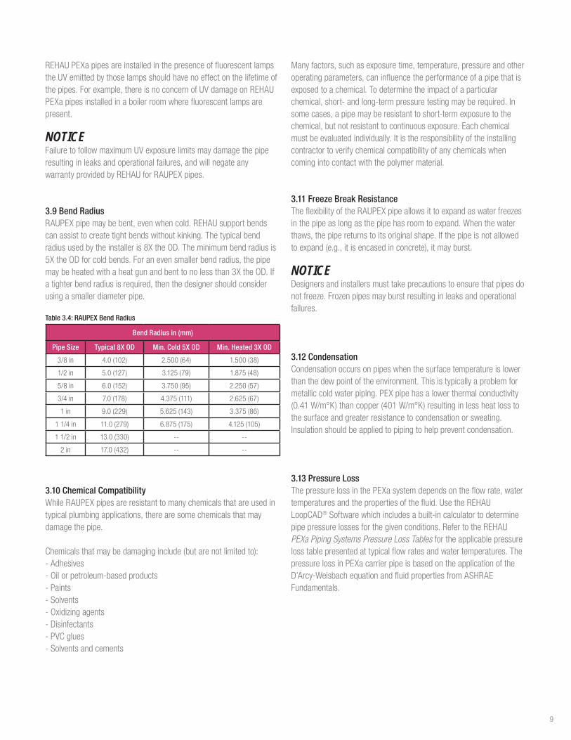
3.9 Bend RadiusRAUPEXpipemaybebent,evenwhencold.REHAUsupportbendscanassisttocreatetightbendswithoutkinking.Thetypicalbendradiususedbytheinstalleris8XtheOD.Theminimumbendradiusis5XtheODforcoldbends.Foranevensmallerbendradius,thepipemaybeheatedwithaheatgunandbenttonolessthan3XtheOD.Ifatighterbendradiusisrequired,thenthedesignershouldconsiderusingasmallerdiameterpipe.
Table 3.4: RAUPEX Bend Radius
Bend Radius in (mm)
Pipe Size Typical 8X OD Min. Cold 5X OD Min. Heated 3X OD
3/8in 4.0(102) 2.500(64) 1.500(38)
1/2in 5.0(127) 3.125(79) 1.875(48)
5/8in 6.0(152) 3.750(95) 2.250(57)
3/4in 7.0(178) 4.375(111) 2.625(67)
1 in 9.0(229) 5.625(143) 3.375(86)
11/4in 11.0(279) 6.875(175) 4.125(105)
11/2in 13.0(330) -- --
2 in 17.0(432) -- --
3.10 Chemical CompatibilityWhileRAUPEXpipesareresistanttomanychemicalsthatareusedintypicalplumbingapplications,therearesomechemicalsthatmaydamagethepipe.
Chemicalsthatmaybedamaginginclude(butarenotlimitedto):-Adhesives-Oilorpetroleum-basedproducts-Paints-Solvents-Oxidizingagents-Disinfectants-PVCglues-Solventsandcements
Manyfactors,suchasexposuretime,temperature,pressureandotheroperatingparameters,caninfluencetheperformanceofapipethatisexposedtoachemical.Todeterminetheimpactofaparticularchemical,short-andlong-termpressuretestingmayberequired.Insomecases,apipemayberesistanttoshort-termexposuretothechemical,butnotresistanttocontinuousexposure.Eachchemicalmustbeevaluatedindividually.Itistheresponsibilityoftheinstallingcontractortoverifychemicalcompatibilityofanychemicalswhencomingintocontactwiththepolymermaterial.
3.11 Freeze Break ResistanceTheflexibilityoftheRAUPEXpipeallowsittoexpandaswaterfreezesinthepipeaslongasthepipehasroomtoexpand.Whenthewaterthaws,thepipereturnstoitsoriginalshape.Ifthepipeisnotallowedtoexpand(e.g.,itisencasedinconcrete),itmayburst.
NOTICEDesignersandinstallersmusttakeprecautionstoensurethatpipesdonotfreeze.Frozenpipesmayburstresultinginleaksandoperationalfailures.
3.12 CondensationCondensationoccursonpipeswhenthesurfacetemperatureislowerthanthedewpointoftheenvironment.Thisistypicallyaproblemformetalliccoldwaterpiping.PEXpipehasalowerthermalconductivity(0.41W/m°K)thancopper(401W/m°K)resultinginlessheatlosstothesurfaceandgreaterresistancetocondensationorsweating.Insulationshouldbeappliedtopipingtohelppreventcondensation.
3.13 Pressure LossThepressurelossinthePEXasystemdependsontheflowrate,watertemperaturesandthepropertiesofthefluid.UsetheREHAULoopCAD®Softwarewhichincludesabuilt-incalculatortodeterminepipepressurelossesforthegivenconditions.RefertotheREHAU PEXa Piping Systems Pressure Loss Tablesfortheapplicablepressurelosstablepresentedattypicalflowratesandwatertemperatures.ThepressurelossinPEXacarrierpipeisbasedontheapplicationoftheD’Arcy-WeisbachequationandfluidpropertiesfromASHRAEFundamentals.
9

4. EVERLOC+ COMPRESSION-SLEEVE FITTINGS
4.1 Fitting Scope TheEVERLOC+compression-sleevesystemisacold-expansionPEXafittingsystemthatisavailableinpolymerandlead-free(LF)brassandisassembledwithaspeciallydesignedPEXacompressionsleeve.ThefittingisdesignedspecificallyforusewithRAUPEXpipeandmustonlybeassembledwiththeEVERLOC+compression-sleevetools.
EVERLOC+fittingsareavailablein3/8,1/2,5/8,3/4,1,11/4,11/2and2in.sizesandareintendedforusewithRAUPEXSDR9coppertubesize(CTS)pipemanufacturedinaccordancewithASTMF876
ForadetaileddescriptionoftheREHAUsystemcomponents,refertotheREHAUSustainable Building Technology Product Catalog (855.312).
4.1.1 Fitting FeaturesEVERLOC+polymerandlead-free(LF)brassfittingshavethefollowingfeatures:1. Foursealingedges2. Pipe stop3. Fittingcollar4. Tooljawbody
Fig. 4.1: EVERLOC+ fitting features
4.1.2 Fitting and Sleeve MarkingsAllpolymerfittingsincludethefollowingmarksforidentification
OR
Fig. 4.2: Fitting size marking (e.g., 3/4”)
Fig. 4.3: Batch code (e.g., production date)
AllLFbrassfittingsaremarked"REHAU"
Allsleevesincludethefollowingmarksforidentification
-Sleevesize(e.g.,1/2")-Batchcodeforproductiondate
Fig. 4.4: Sleeve markings
1
2
4
3
10

4.1.3 Polymer FittingsEVERLOC+polymerfittingsareavailableincouplings,tees,elbows,multi-portteesandplugs.Allpolymerfittingsareproducedfromapolyphenylsulfone(PPSU)materialthatmeetstherequirementsofNSF61forhealtheffectsofdrinkingwatersystemcomponentsandcomplieswiththelead-freerequirementsoftheU.S.SafeDrinkingWaterAct.SeealsoREHAUTechnical Bulletin TB265 EVERLOC+ Polymer Fitting Material - PPSU.
Fig. 4.5: EVERLOC+ polymer fittings
4.1.4 Lead Free (LF) Brass FittingsEVERLOC+LFbrassfittingsareavailableascouplings,tees,elbows,plugsandtransitionfittingstoNPTthreadandcoppersolderconnections.AllmetalfittingsareproducedfromECOBRASS®(UNS69300orCW724R)thatmeetstherequirementsofNSF61forhealtheffectsofdrinkingwatersystemcomponentsandcomplieswiththelead-freerequirementsoftheU.S.SafeDrinkingWaterAct.SeealsoREHAUTechnical Bulletin TB264 EVERLOC+ Lead-free Brass Fitting Material.
Fig. 4.6: EVERLOC+ LF brass fittings
4.1.5 Metal ManifoldsManifoldsare1in.TypeLcopperwithEVERLOC+LFbrassfittingsbrazedintotheheader.
Fig. 4.7: EVERLOC+ metal manifold
4.1.6 PEXa Compression SleevesEVERLOC+compressionsleevesareproducedusingaspeciallyformulatedPEXamaterialandaredesignedspecificallyforusewithEVERLOC+fittingsandRAUPEXpipe.EVERLOC+compressionsleeveshavethefollowingfeatures:-Co-extrudedplatinum-coloredPEcoating-Squarelycutendsthatcanbeslidoverthepipeineitherdirection-Groovedandroughenedinsidesurfaceforlockingthesleeveintoplaceonceslidoverthepipeandfitting
Fig. 4.8: EVERLOC+ compression sleeves
4.1.8 CertificationsTheEVERLOC+compression-sleevesystemiscertifiedtothefollowingstandards:-ASTMF877,Standard Specification for Crosslinked Polyethylene
(PEX) Hot- and Cold-Water Distribution Systems-NSF/ANSI14,Plastic Piping System Components and Related
Materials-NSF/ANSI61,Drinking Water System Components – Health Effects-NSF/ANSI372,Drinking Water System Components – Lead Content-CSAB137.5,Crosslinked polyethylene (PEX) Tubing Systems for
Pressure Applications
11
4.2 Fitting Assembly Beforestartingtheinstallationprocess,readtheEVERLOC+ Compression-sleeve System Product Instructions (855.724).
AssemblingtheEVERLOC+compression-sleevesystemrequirestheuseoftheEVERLOC+compression-sleevetools.OnlymakeEVERLOC+compression-sleevejointswiththesetools.RefertoEVERLOC+ Power Tool Product Instruction Manual (855.725),EVERLOC+ XL Power Tool Product Instruction Manual(855.728)andEVERLOC+ XL Expander Tool Product Instruction Manual(855.729)foracompleteunderstandingofoperation,careanduseoftheEVERLOC+compression-sleevetools.
WARNINGReadtheinstructionmanualfortheEVERLOC+compression-sleevetoolsbeforeuseandfollowallsafetyprecautions-improperusecancauseseriouspersonalinjury.
WARNINGToreducetheriskofpermanenteyeinjury,alwayswearclose-fittingprotectiveeyewearwithsideprotection.Eyewearmustbeimpact-ratedandmarkedascomplyingwithANSIZ87.
NOTICEUseonlyEVERLOC+compression-sleevetoolsforassemblyandinstallation.Useofothertoolswillresultinanimproperlyassembledjoint,whichmayresultinleakingandpropertydamage.
ThebasicprocessofassemblinganEVERLOC+compression-sleevejointisasfollows:-Makeaclean,squarecutoftheRAUPEXpipeusingaRAUPEX
cutter-SlidetheEVERLOC+compressionsleeveovertheRAUPEXpipeensuringthesleeveisaminimumoftwotimesthelengthofthesleevefromtheendofthecutpipetoallowforexpansionofthepipeonly-ExpandtheRAUPEXpipetwice,ensuringtheexpanderheadisrotated1/2ofoneexpanderheadsegmentbetweenexpansions,usingtheEVERLOC+compression-sleevetools-InserttheEVERLOC+compression-sleevefittingintotheexpandedendoftheRAUPEXpipeuntilthepipeistouchingthepipestoponthefitting-CompresstheEVERLOC+compressionsleeveovertheRAUPEXpipeandEVERLOC+compression-sleevefittingusingtheEVERLOC+compression-sleevetools
Requiredassemblytoolsinclude:-RAUPEXcutter-EVERLOC+compression-sleevetools-EVERLOC+expanderheadsandcompressionjaws
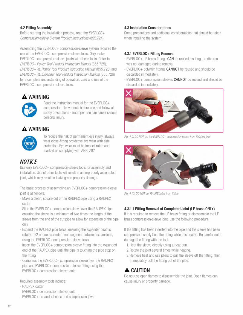
4.3 Installation Considerations Someprecautionsandadditionalconsiderationsthatshouldbetakenwheninstallingthesystem.
4.3.1 EVERLOC+ Fitting Removal -EVERLOC+LFbrassfittingsCANbereused,aslongtheribareawasnotdamagedduringremoval.-EVERLOC+polymerfittingsCANNOTbereusedandshouldbediscardedimmediately.-EVERLOC+compressionsleevesCANNOTbereusedandshouldbediscardedimmediately.
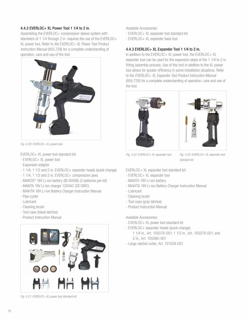
Fig. 4.9: DO NOT cut the EVERLOC+ compression sleeve from finished joint
Fig. 4.10: DO NOT cut RAUPEX pipe from fitting
4.3.1.1 Fitting Removal of Completed Joint (LF brass ONLY)IfitisrequiredtoremovetheLFbrassfittingordisassembletheLFbrasscompression-sleevejoint,usethefollowingprocedure:
Ifthefittinghasbeeninsertedintothepipeandthesleevehasbeencompressed,safelyholdthefittingwhileitisheated.Becarefulnottodamagethefittingwiththetool.
1. Heatthesleevedirectlyusingaheatgun.2. Rotatethejointseveraltimeswhileheating.3. Removeheatanduseplierstopullthesleeveoffthefitting,thenimmediatelypullthefittingoutofthepipe.
CAUTIONDonotuseopenflamestodisassemblethejoint.Openflamescancauseinjuryorpropertydamage.
12

Fig. 4.11: Heating EVERLOC+ compression sleeve with heat gun
Fig. 4.12: Removing pipe from LF brass fitting
Forre-assemblyofajoint,thefollowingshouldbeconsidered:-Theendofthepipewherethepreviousfittinghadbeeninstalledmustbecompletelycutoffpriortomakinganewjoint.Cuttingoffaminimumof3in(approximately75mm)isrecommended.
Fig. 4.13: Cut off 3 in. of pipe from end prior to making new joint
4.3.1.2 Fitting Removal of Partially Completed Joint (LF Brass ONLY)Ifthefittinghasbeeninsertedintothepipe,butthesleevehasnotbeencompressed,attempttoremoveitwithoutdamagingthefitting.Iffittingcannotbeeasilyremoved,heat1to11/2in(25to38mm)ofthepipethatcoversthefittingandpullthefittingoutofthepipe.
4.3.2 Protecting EVERLOC+ JointsREHAUpermitsEVERLOC+compression-sleevejoints(polymerandLFbrass)tobeburiedorconcealed.REHAUrecommendsthreadedconnectionsneverbeburiedorconcealedastheymustbeaccessibleforperiodicinspection,perprevailinglocalcodes.
TherequirementtowrapanEVERLOC+jointcandependonmanyfactorsincludinglocationandthepresenceofothermaterialsthatcontactorcancomeincontactwiththejoint.
WhenwrappinganEVERLOC+joint,thefollowingisrequired:-Wrapthejoint,ensuringaminimumof50%overlapofthetape-Avoidwrinklesorkinksinthetapeandensurethejointiscompletelycovered,extendingontothepipeasnecessary-Indicatethelocationofeachjointasrequiredonthe“as-built”drawings
Fig. 4.14: REHAU Protective Tape, Red Fig. 4.15: Linerless Rubber Tape, Black
Note:UseonlyREHAUrecommendedprotectivetapesreferencedinREHAUTechnical Bulletin TB266 Protecting EVERLOC+ Joints.Donotuseothertypesoftapes(e.g.,ducttape,standardelectricaltape)towrapthejoint,aschemicalsintheadhesivemaynotbecompatiblewiththePPSUfittingmaterialorthePEXapipe.
Note:Neveruseheatshrinktubing(e.g.,RAUCROSS)towrapthejoint,astheextremelyhightemperaturesproducedfromaheatgunwillsoftenthepipeandmaycauseittopullawayfromthefitting.
Fig. 4.16: DO NOT use heat shrink tubing for EVERLOC+ joints
4.3.2.1 Concealed in Inaccessible Locations WhenEVERLOC+jointsareconcealedbutarestillinopenairspace(e.g.,behinddrywall),itisnotnecessarytowrapthejoint.However,theinstallershouldensurethefittingdoesnotcomeincontactwithchemicals(e.g.,PVCglues,solventsandcements)thatcoulddamagethefittingmaterial.
4.3.2.2 Buried in a Concrete Slab or sub-base underneath slabWhenburyinganEVERLOC+polymerjointdirectlyinaconcreteslab,orinthesub-baseunderneaththeslab,itisnotnecessarytowrapthejoint.However,therearesomeadditivesinconcreteorchemicalsusedintheinstallationthatcouldpotentiallydamagethefittingmaterial,andinthiscase,wrappingisrecommended.EVERLOC+LFbrassjointsburieddirectlyinaconcreteslaborinthesub-baseunderneaththeslabmustbewrapped.
13

4.3.2.3 Buried in Soil:WhenburyingEVERLOC+jointsinsoil,outsideofastructure,thejointmustbewrapped.
4.3.2.4 With Foaming Agents:Foamingagentsandsolventsinclosed-cellfoaminsulationkitscandamagethePPSUfittingmaterial.Therefore,itisnecessarytowrappolymerfittingsinaprotectivetapetoprotectfrompolyurethanefoams.
4.3.3 Pressure TestingThecompression-sleevejointisreadyforimmediatepressuretestanduseaftercompletionoftheassemblyprocess.Thereisnowaittimeforthesystemtobeputintoservice.SeeSection6.17.2forREHAUpressure test procedures.
4.3.4 Pressure and Temperature RatingsThemaximumtemperatureandpressureratingsoftheREHAUPEXaplumbingsystemareinaccordancewithASTMF877andCSAB137.5forSDR9PEX,asdefinedinSection3.4.
4.3.5 Ultraviolet ResistanceThefittingsandsleevesmustneverbestoredindirectsunlightorstoredoutsideoftheoriginalcardboardpackaging.Inaddition,thesystemisnotintendedforpermanentoutdoorapplicationsorinareaswithcontinuousexposuretoUV.
4.3.6 Freeze Break ResistanceTheflexibilityoftheRAUPEXpipeallowsittoexpandaswaterfreezesinthepipeaslongasthepipehasroomtoexpand.However,thisflexibilitydoesnotensuretheintegrityofthejoint.Therefore,installersmusttakeprecautionstoensurethatpipesandfittingsdonotfreeze.Freezingmayresultinleaksandoperationalfailures.
4.3.7 Chlorine ResistanceEVERLOC+compression-sleevejointshaveachlorineresistanceratingbasedontheratingsofRAUPEXpipe,asdefinedinSection3.7.
4.3.8 Stress Corrosion ResistanceEVERLOC+LFbrassfittingshavebeentestedinaccordancewithNSF/ANSI14andcomplywiththerequirementforstresscorrosionresistance.However,fittingsshouldnotbeexposedtoharmfulchemicalsoraggressivewaterconditionsthatcouldresultinopera-tionalfailures.
4.3.9 Chemical CompatibilityTherearecertainchemicalsthatcandamagetheEVERLOC+compression-sleevesystem.Thisappliestoexternalexposureofchemicalsandtothetransportofsuchchemicalsbythepipingsystem.Chemicalsthatmaydamagethecompression-sleevesysteminclude(butarenotlimitedto):-AdhesivesandtapesotherthanthoserecommendedbyREHAU-Oil/petroleum-basedproducts-Paints,solvents-Oxidizingagents(e.g.,bleach)-Disinfectants(e.g.,separatedosingunitintegratedintobuildingdistributionsystem)-PVCglues,solventsandcements
Fig. 4.17: DO NOT use harmful chemicals near EVERLOC+ fittings
Ensurethattheemployedsealants,cleaningagents,buildingfoams,insulation,protectivetape,adhesivetapeorthreadsealantsdonotcontainanycomponentswhichcausestresscrackingorcorrosion,suchasammonia,ammonia-bearing,aromaticandoxygenatedsolvents(e.g.,ketoneandether),chlorinatedhydrocarbonsorchlorideionswhichcanleach.
Protectsystemsagainstcontacttochemicalsanddamage.Onlyuseleakdetectionagents(e.g.,foamingagents)approvedbytherespectivemanufacturerforPPSUmaterials.Onlyusesealants,threadsealants,cleaningagents,buildingfoams,insulation,protectivetape,adhesivetapeandfluxapprovedbytherespectivemanufacturerforthePPSUmaterials.Checkthecompatibilityofmaterialsforthecorrespondingareaofapplicationwiththemanufacturer.
Contactwitharomaticandoxygenatedsolvents(e.g.,ketoneandether)aswellashalogenatedhydrocarbons(e.g.,chlorinatedhydrocarbons)isnotpermitted.Contactwithwater-basedacrylicpaintsandadhesive/protectiveprimersisnotpermitted.
14

4.3.10 Copper SolderingPropersolderingtechniquesmustbefollowedwhensolderingallcompression-sleevefittingsaccordingtotheCopper Development Association (CDA) Handbook: -Thesurfaceofthefittingsolderingareamustbeproperlycleanedforagoodsolderconnection.Applyingfluxisnotconsideredsufficientcleaningforthesolderingarea.Usingapropersandingorbrushtechniqueisnecessarytoremovethesurfaceoxides.Inordertopreventfurtherformationofoxides,thefluxshouldbeappliedimmediatelyafterthecleaningprocess.Aproperfluxthatiscompatiblewiththebrassalloymustbeused.-Caremustbetakentonotoverheatthesolderingsurfaceasthiscanleadtotheformationofoxidespreventinggoodadhesionofthesoldermaterial.Itisimperativethatthefittingisheatedevenlyaroundtheentiresurfacesoastonotoverheatoneparticulararea.-Allcompletedsolderjointsmustbetestedforjointintegrityfollowingtheproceduresprescribedbyprevailinglocalcodes.
4.4 EVERLOC+ Compression-sleeve ToolsAssemblingtheEVERLOC+compression-sleevesystemrequirestheuseoftheEVERLOC+compression-sleevetools.OnlymakeEVERLOC+compression-sleevejointswiththesetools.
Beforeuse,readandunderstandthefollowingsafetysymbolswhicharefoundontheEVERLOC+compression-sleevetools.
SafetyAlertSymbol–Toreducetheriskofinjury,followthespecifiedsafetyinstructions.
Readandfollowallsafetyprecautionsintheinstructionmanual.Improperusecanleadtoseriouspersonalinjuryorpropertydamage.
Toreducetheriskofseriouseyeinjury,alwayswearproper eye protection.
Riskofelectricshock.Neveroperatethepowertoolindamporwetconditions.Neverexposetorainorsubmergeinwaterorotherliquids.Neveroperatethepowertoolnearwiresorcablescarryingelectriccurrent.
Toreducetheriskofseverepersonalinjury,includingcrushandlacerationinjury,keepfingers,handsandallpartsofyourbodyawayfromtheexpanderhead,hydraulicslideandcompressionjawsduringoperation.
NOTICEUseonlyEVERLOC+compression-sleevetoolsforassemblyandinstallation.Useofothertoolswillresultinanimproperlyassembledjoint,whichmayresultinleakingandpropertydamage.
4.4.1 EVERLOC+ Power Tool 3/8 to 1 in.ForassemblyofEVERLOC+fittingsinsizes3/8through1in.UsetheEVERLOC+powertool.RefertoEVERLOC+ Power Tool Product Instruction Manual (855.725)foracompleteunderstandingofoperation,careanduseofthetool
Fig. 4.18: EVERLOC+ power tool
EVERLOC+powertoolstandardkit:-EVERLOC+powertool-Expansionadapter-1/2,3/4and1in.EVERLOC+expanderheads(quickchange)-1/2,3/4and1in.EVERLOC+compressionjaws-DEWALT®12VLi-ionbattery(DCB127)(2batteriesperkit)-DEWALT12V/20VLi-ioncharger120VAC(DCB107)-DEWALT12V/20VLi-ionBatteryChargerInstructionManual-Pipe cutter-Lubricant-Cleaningbrush-Tool case-Product Instruction Manual
Fig. 4.19: EVERLOC+ power tool standard kit
AvailableAccessories:-3/8in.expanderhead(quickchange)-3/8in.compressionjaws-5/8in.expanderhead(quickchange)-5/8in.compressionjaws
15
4.4.2 EVERLOC+ XL Power Tool 1 1/4 to 2 in.AssemblingtheEVERLOC+compression-sleevesystemwithdiametersof11/4through2in.requirestheuseoftheEVERLOC+XLpowertool.Refertothe EVERLOC+ XL Power Tool Product Instruction Manual(855.728)foracompleteunderstandingofoperation,careanduseofthetool.
Fig. 4.20: EVERLOC+ XL power tool
EVERLOC+XLpowertoolstandardkit:-EVERLOC+XLpowertool-Expansionadapter-11/4,11/2and2in.EVERLOC+expanderheads(quickchange)-11/4,11/2and2in.EVERLOC+compressionjaws-MAKITA®18VLi-ionbattery(BL1840B)(2batteriesperkit)-MAKITA18VLi-ioncharger120VAC(DC18RC)-MAKITA18VLi-ionBatteryChargerInstructionManual-Pipe cutter-Lubricant-Cleaningbrush-Toolcase(blacklatches)-Product Instruction Manual
Fig. 4.21: EVERLOC+ XL power tool standard kit
AvailableAccessories:-EVERLOC+XLexpandertoolstandardkit-EVERLOC+XLexpanderbasetool
4.4.3 EVERLOC+ XL Expander Tool 1 1/4 to 2 in. InadditiontotheEVERLOC+XLpowertool,theEVERLOC+XLexpandertoolcanbeusedfortheexpansionstepsofthe11/4to2in.fittingassemblyprocess.UseofthistoolinadditiontotheXLpowertoolallowsforgreaterefficiencyinsomeinstallationsituations.RefertotheEVERLOC+ XL Expander Tool Product Instruction Manual (855.729)foracompleteunderstandingofoperation,careanduseofthetool.
Fig. 4.22: EVERLOC+ XL expander tool Fig. 4.23: EVERLOC+ XL expander tool
standard kit
EVERLOC+XLexpandertoolstandardkit:-EVERLOC+XLexpandertool-MAKITA18VLi-ionbattery-MAKITA18VLi-ionBatteryChargerInstructionManual-Lubricant-Cleaningbrush-Toolcase(graylatches)-Product Instruction Manual
AvailableAccessories:-EVERLOC+XLpowertoolstandardkit-EVERLOC+expanderheads(quickchange):
11/4in.,Art.105078-001;11/2in.,Art.105079-001;and2in.,Art.105080-001
-Largeratchetcutter,Art.131558-001
16

5. DESIGN CONSIDERATIONS
5.1 Pipe SizingThedesignandlayoutofthebuildinghot-andcold-waterdistributionsystemshallcomplywithacceptedplumbingengineeringpracticeandasperprevailinglocalcodes.
TheREHAUPEXaplumbingsystemconsistsofRAUPEXUVshieldPEXapipeandtheEVERLOC+compression-sleevefittingsystemandcanbedesignedandsizedperthefollowingmodelplumbingcodes:
-ICCInternationalPlumbingCode(IPC)-ICCInternationalResidentialCode(IRC)-IAMPONationalStandardPlumbingCode(NSPC)-IAPMOUniformPlumbingCode(UPC)-NRCCNationalPlumbingCodeofCanada(NPCC)
Inaddition,aproperlydesignedplumbingsystemshouldfollowtheengineeringprinciplesaspertheAmericanSocietyofPlumbingEngineers(ASPE)Plumbing Engineering Design Handbook Volume II orequivalent.
Forsizingasysteminresidentialandlightcommercialbuildings,usethewatersupplyfixtureunit(WSFU)methodtodeterminetherequiredload(GPM)andresultingpipesizeaspublishedinthemodelplumbingcodes.Alternatively,orinlargerbuildings,theuniformfrictionheadlossmethodcanbeutilized.
5.1.1 Standard Dimension RatioRAUPEXpipeisinaccordancetothedimensionalstandardsinASTMF876andCSAB137.5.RAUPEXiscoppertubesize(CTS)outsidediameter(OD)whichmeansthattheactualODofthepipeis1/8in.(3.18mm)largerthanthenominalsize.
Wallthicknessisdefinedbythestandarddimensionalratio(SDR).RAUPEXUVshieldpipeisSDR9,whichequatestotheoutsidediameterbeingapproximatelyninetimesthewallthickness.SincePEXpipehasathickerwallthancoppertube,theinsidediameter(ID)isslightlysmaller.However,sincePEXpipeisnotsusceptibletotheerosionandcorrosionissuesofcoppertube,plumbingsystemscanbedesignedathighervelocitieswhichallowforcomparablesizingofasystem.
5.1.2 Determining Friction LossThepressurelossfortheREHAUPEXaplumbingsystemcanbecalculatedusingtheREHAU PEXa Piping Systems Pressure Loss Tables (855.861)availableonlineontheREHAUResourceCenterorusingtheREHAULoopCADsoftwarepressurelosscalculatortool.
5.1.3 Velocity ConsiderationsThemaximumvelocityofwaterflow(feet/second–fps)intheplumbingsystemshouldbeconsideredwhensizingaREHAUPEXaplumbingsystem.Todeterminethepipesize,theWSFUloadcanbecorrelatedtoflowrate(GPM)fromtablespublishedinthemodelplumbingcodes.
Oncetheflowrateisdetermined,thepipecanbesizedbasedontheallowablemaximumvelocitiesperprevailinglocalcodes.
Thedesignercanusethefollowingtablesasaguideline:
Table 5.1: Maximum Velocity of Water Flow
Cold-Water
Piping
- Typicalplumbingcodesstatemaximumvelocityof8ft/sec
- REHAUrecommendsamaximumdesignvelocityof10ft/sec
Hot-Water
Piping
- Typicalplumbingcodesstatemaximumvelocityof5ft/sec
- REHAUrecommendsamaximumdesignvelocityof8ft/sec
Hot-Water
Recirculation
Return Piping
-Maximumvelocityof2ft/sec
-Maximumoperatingtemperatureof140°F(60°C)
Table 5.2: GPM per Pipe Size
Pipe SizeGPM
@ 2 fpsGPM
@ 5 fpsGPM
@ 8 fpsGPM
@ 10 fps
3/8in 0.6 1.6 2.5 3.2
1/2in 1.1 2.9 4.6 5.8
3/4in 2.3 5.7 9.1 11.3
1 in. 3.8 9.4 15.0 18.8
11/4in 5.7 14.0 22.3 28.1
11/2in 8.0 19.7 31.3 39.1
2 in 13.7 33.4 53.8 67.1
17

5.2 Equivalent Length of FittingsItiscommonpracticefordesignerstoconvertthepressuredropacrossfittingstoanaverageequivalentlengthofpipe.Theseequivalentlengthsareaddedtothetotalpipelength.Designerscancalculatetotalpressurelossusingthisadjustedpipingsystemlength.
Table 5.3: Equivalent Length of Fittings
CouplingsFitting Description Equivalent Length (ft)
3/8x3/8in.EVERLOC+LFBrassCoupling 1.1
1/2x1/2in.EVERLOC+PolymerCoupling 0.4
5/8x5/8in.EVERLOC+LFBrassCoupling 1.0
3/4x1/2in.EVERLOC+PolymerCoupling 2.1
3/4x3/4in.EVERLOC+PolymerCoupling 0.8
1x3/4in.EVERLOC+PolymerCoupling 2.7
1x1in.EVERLOC+PolymerCoupling 1.1
11/4x3/4in.EVERLOC+LFBrassCoupling 3.5
11/4x1in.EVERLOC+PolymerCoupling 4.0
11/4x11/4in.EVERLOC+PolymerCoupling 2.0
11/2x1in.EVERLOC+PolymerCoupling 4.8
11/2x11/2in.EVERLOC+PolymerCoupling 2.0
2x1/2in.EVERLOC+LFBrassCoupling 3.5
2x3/4in.EVERLOC+LFBrassCoupling 3.8
2x1in.EVERLOC+LFBrassCoupling 5.2
2x11/4in.EVERLOC+LFBrassCoupling 5.3
2x11/2in.EVERLOC+LFBrassCoupling 6.1
2x2in.EVERLOC+PolymerCoupling 2.2
Elbows (PEX to PEX)Fitting Description Equivalent Length (ft)
1/2x1/2in.EVERLOC+PolymerElbow 1.9
5/8x5/8in.EVERLOC+LFBrassElbow 5.4
3/4x3/4in.EVERLOC+PolymerElbow 7.0
1x1in.EVERLOC+PolymerElbow 10.7
11/4x11/4in.EVERLOC+PolymerElbow 14.2
11/2x11/2in.EVERLOC+PolymerElbow 16.0
11/2x11/2in.EVERLOC+LFBrass45°Elbow 3.4
2x2in.EVERLOC+PolymerElbow 24.2
Tees
Fitting Description
Equivalent Length (ft)
RUN
Equivalent Length (ft) BRANCH
1/2x1/2x1/2in.EVERLOC+PolymerTee 0.8 4.4
1/2x1/2x3/4in.EVERLOC+PolymerTee - 4.1
3/4x1/2x1/2in.EVERLOC+PolymerTee 2.4 4.3
3/4x1/2x3/4in.EVERLOC+PolymerTee 2.4 7.6
3/4x3/4x1/2in.EVERLOC+PolymerTee 1.3 4.0
3/4x3/4x3/4in.EVERLOC+PolymerTee 1.2 7.6
3/4x3/4x1in.EVERLOC+PolymerTee - 6.8
1x1x1/2in.EVERLOC+PolymerTee 1.6 3.9
1x3/4x3/4in.EVERLOC+PolymerTee 2.8 6.5
1x3/4x1in.EVERLOC+PolymerTee 3.1 10.9
1x1x3/4in.EVERLOC+PolymerTee 1.2 6.7
1x1x1in.EVERLOC+PolymerTee 1.6 10.6
11/4x1x3/4in.EVERLOC+LFBrassTee 3.7 5.4
11/4x1x1in.EVERLOC+PolymerTee 3.8 9.7
11/4x1x11/4in.EVERLOC+LFBrassTee 4.3 9.6
11/4x11/4x1/2in.EVERLOC+LFBrassTee 0.8 5.0
11/4x11/4x3/4in.EVERLOC+LFBrassTee 1.3 5.5
11/4x11/4x1in.EVERLOC+PolymerTee 2.3 10.1
11/4x11/4x11/4in.EVERLOC+PolymerTee 2.2 14.4
11/2x1x3/4in.EVERLOC+LFBrassTee 6.8 6.8
11/2x1x1in.EVERLOC+LFBrassTee 5.5 7.9
11/2x1x11/2in.EVERLOC+LFBrassTee 5.6 12.4
11/2x11/4x3/4in.EVERLOC+LFBrassTee 4.5 5.5
11/2x11/4x1in.EVERLOC+LFBrassTee 4.4 8.1
11/2x11/4x11/4in.EVERLOC+LFBrassTee 4.5 9.5
11/2x11/4x11/2in.EVERLOC+LFBrassTee 4.3 10.9
11/2x11/2x1/2in.EVERLOC+LFBrassTee 1.0 4.9
11/2x11/2x3/4in.EVERLOC+LFBrassTee 1.0 5.4
11/2x11/2x1in.EVERLOC+PolymerTee 2.2 9.1
11/2x11/2x11/4in.EVERLOC+LFBrassTee 1.7 9.6
11/2x11/2x11/2in.EVERLOC+PolymerTee 2.6 17.0
2x11/4x2in.EVERLOC+LFBrassTee 6.7 14.9
2x11/2x3/4in.EVERLOC+LFBrassTee 5.8 5.7
2x11/2x1in.EVERLOC+LFBrassTee 6.2 7.7
2x11/2x11/4in.EVERLOC+LFBrassTee 6.3 9.5
2x11/2x11/2in.EVERLOC+LFBrassTee 6.4 11.2
2x11/2x2in.EVERLOC+LFBrassTee 6.5 14.6
2x2x1/2in.EVERLOC+LFBrassTee 1.1 5.0
2x2x3/4in.EVERLOC+LFBrassTee 1.0 5.9
2x2x1in.EVERLOC+PolymerTee 3.2 9.0
2x2x11/4in.EVERLOC+LFBrassTee 1.9 9.7
2x2x11/2in.EVERLOC+LFBrassTee 1.9 10.9
2x2x2in.EVERLOC+PolymerTee 4.0 25.3
18
Elbows (PEX to transition)
Fitting DescriptionEquivalent Length (ft)
1/2x1/2in.CMaleor3/8in.CFemaleEVERLOC+LFBrassElbow 7.4
1/2x1/2in.CFemaleEVERLOC+LFBrassElbow 7.2
3/4x3/4in.CFemaleEVERLOC+LFBrassElbow 7.1
3/4x3/4in.CMaleEVERLOC+LFBrassElbow 7.4
1/2x1/2in.MPTEVERLOC+LFBrassDropEarElbow 7.6
1/2x1/2in.FPTEVERLOC+LFBrassDropEarElbow 4.9
3/4x3/4in.MPTEVERLOC+LFBrassElbow 7.5
3/4x3/4in.MPTEVERLOC+LFBrassDropEarElbow 7.7
3/4x3/4in.FPTEVERLOC+LFBrassDropEarElbow 9.0
1x1in.FPTEVERLOC+LFBrassDropEarElbow 13.6
Adapters (PEX to copper)
Fitting DescriptionEquivalent Length (ft)
1/2x1/2in.CFemaleEVERLOC+LFBrassAdapter 2.3
1/2x1/2in.CMaleor3/8in.CFemaleEVERLOC+LFBrassAdptr 2.4
1/2x3/4in.CFemaleEVERLOC+LFBrassAdapter 4.0
3/4x1/2in.CMaleEVERLOC+LFBrassAdapter 0.3
3/4x1/2in.CFemaleEVERLOC+LFBrassAdapter 0.5
3/4x1in.CFemaleEVERLOC+LFBrassAdapter 3.9
3/4x3/4in.CFemaleEVERLOC+LFBrassAdapter 2.7
3/4x3/4in.CMaleEVERLOC+LFBrassAdapter 2.6
1x1in.CFemaleEVERLOC+LFBrassAdapter 3.5
1x1in.CMaleEVERLOC+LFBrassAdapter 3.3
11/4x11/4in.CFemaleEVERLOC+LFBrassAdapter 4.1
11/4x11/4in.CMaleEVERLOC+LFBrassAdapter 4.3
11/2x11/2in.CFemaleEVERLOC+LFBrassAdapter 5.3
11/2x11/2in.CMaleEVERLOC+LFBrassAdapter 5.4
2x2in.CFemaleEVERLOC+LFBrassAdapter 7.0
2x2in.CMaleEVERLOC+LFBrassAdapter 6.9
Adapters (PEX to MPT/FPT)
Fitting DescriptionEquivalent Length (ft)
3/8x1/2in.MPTEVERLOC+LFBrassAdapter 2.4
1/2x1/2in.FPTEVERLOC+LFBrassAdapter 2.8
1/2x1/2in.MPTEVERLOC+LFBrassAdapter 3.3
5/8x1/2in.MPTEVERLOC+LFBrassAdapter 2.9
5/8x3/4in.MPTor1/2in.CFemaleEVERLOC+LFBrassAdptr 3.6
3/4x3/4in.FPTEVERLOC+LFBrassAdapter 2.8
3/4x3/4in.MPTEVERLOC+LFBrassAdapter 3.4
3/4x1in.MPTEVERLOC+LFBrassAdapter 4.3
1x3/4in.FPTEVERLOC+LFBrassAdapter 0.1
1x1in.FPTEVERLOC+LFBrassAdapter 3.6
1x1in.MPTEVERLOC+LFBrassAdapter 3.8
11/4x11/4in.MPTEVERLOC+LFBrassAdapter 4.9
11/2x11/2in.MPTEVERLOC+LFBrassAdapter 5.9
2x2in.MPTEVERLOC+LFBrassAdapter 7.3
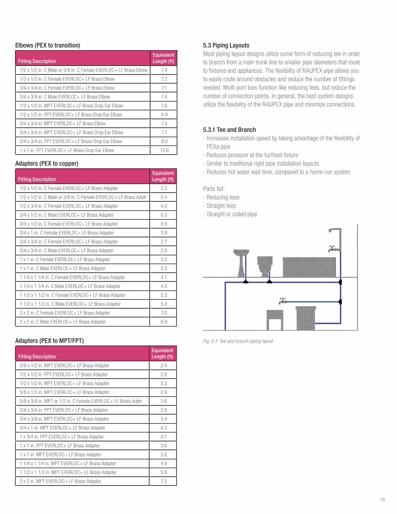
5.3 Piping Layouts Mostpipinglayoutdesignsutilizesomeformofreducingteeinordertobranchfromamaintrunklinetosmallerpipediametersthatroutetofixturesandappliances.TheflexibilityofRAUPEXpipeallowsyoutoeasilyroutearoundobstaclesandreducethenumberoffittingsneeded.Multi-portteesfunctionlikereducingtees,butreducethenumberofconnectionpoints.Ingeneral,thebestsystemdesignsutilizetheflexibilityoftheRAUPEXpipeandminimizeconnections.
5.3.1 Tee and Branch-IncreasesinstallationspeedbytakingadvantageoftheflexibilityofPEXapipe-Reducespressureatthefurthestfixture-Similartotraditionalrigidpipeinstallationlayouts-Reduceshotwaterwaittime,comparedtoahome-runsystem
Parts list:-Reducingtees-Straighttees-Straightorcoiledpipe
Fig. 5.1: Tee and branch piping layout
19

5.4 Thermal Expansion and ContractionWhenthermalexpansionisanticipated,pipemovementshouldbecontrolledtoavoidchangesthatcoulddamagethepipingsystem.Anchoringanduseofexpansionloopsmaybeusedtoaccomplishthis.Allowingforcontrolledexpansionandcontractioninmultiplepartsofapipingsystemisanacceptedmeansofpreventingaddedstressesinotherpartsofthesystem.
RAUPEXpipingsystemsexhibitahigherexpansionandcontractionratewhensubjectedtochangesintemperatureascomparedtometallicpipingsystems.Becauseofitslowermodulusofelasticity,RAUPEXpipeislessrigidthanmetallicpipinganddevelopslessforcethanmetallicpipewhenexposedtotemperaturechanges.
5.4.1 Calculating Thermal Expansion of RAUPEX PipeWhenapipeisanchoredatoneendbutcanotherwisefreelymoveintheaxialdirection,anincreaseintemperaturecausesthepipetoincreaseinoveralllength.Adecreaseintemperaturecausesadecreaseinlength.
Thefollowingequationpredictsthenetexpansion/contractioninthelengthofafullyunrestrainedpipethatoccursinconsequenceofagivenchangeintemperature:
(1)
where,ΔL=changeinpipelength,in.α=coefficientoflinearexpansion/contraction,in/ft°FL=initialpipelength,in.ΔT=changeinpipetemperature,°FNote:SeeTable3.1forcoefficientoflinearexpansion
5.4.2 Calculating L-bend and U-bend for RAUPEX PipeRAUPEXpipewillexpandandcontractwhenheatedorcooledduetoachangeinwatertemperatureorambienttemperature.ThermalexpansionofRAUPEXpipemustbeconsideredinthedesignandinstallationofthepipingsystem.Fixedanchorpoints,guidesandexpansionloopsshouldbeutilizedtoaccountfortheexpansionandcontractionofthepipetopreventanydamagetothepipingsystem.
5.3.2 Multi-port Tee-Minimizesnumberofconnections-Combinesteeandbranchandhome-runconcepts-Systemsarepressure-balancedateachmanifold-Reduceshotwaterwaittime,comparedtoahome-runsystem
Parts list:-Flow-throughmulti-porttees-Closed-endmulti-porttees-Straightorcoiledpipe
Fig. 5.2: Multi-port tee piping layout
5.3.3 Home-run-Generallyforresidentialinstallations-Eliminatesmostfittings-Balancespressuretoallfixtures-Increaseshotwaterwaittime,comparedtoteeandbranchandremotemulti-portdesigns-Usesmorepipe-Mayrequiremoreholestobedrilledinjoistspaces
Parts list:-Multi-porttees-Straightorcoiledpipe
Fig. 5.3: Home-run piping layout
20

Fig. 5.4: L-bend and U-bend
CalculationofthelengthofoffsetforanL-bendorwidthandheightofaU-bendcanbedeterminedasfollows,whereL=lengthofoffsetlegforL-bend(ft),perASHRAE2016 Chap 46 Pipe, Tubes and Fittings
(2)
D=actualpipeoutsidediameter(in),sourceforRAUPEXisTable3.2E=modulusofelasticity(psi),sourceforRAUPEXisTable3.1C=constant,144(in²/ft²)S
A=allowablestressrange
andΔ=anchor-to-anchorthermalexpansionorcontraction(in)
(3)
where,α=coefficientoflinearexpansion([in/[ft°F]),sourceforRAUPEXisTable3.1dT=temperaturedifferential(°F)L
FP=singleplanelengthbetweenfixedpoints(anchors)(ft)
ThewidthofaU-bendiscalculatedwiththefollowingequation,whereW=widthofU-bend(ft),perASHRAE2016 Chap 46 Pipe, Tubes and Fittings
(4)
TheheightofaU-bendiscalculatedwiththefollowingequation,whereH=heightofU-bend(ft),perASHRAE2016 Chap 46 Pipe, Tubes and Fittings
(5)
5.4.3 RisersAlwayscomplywithprevailinglocalcodesregardingtheuseofPEXpipeinriserapplications.RAUPEXshouldbesupportedverticallyeveryfloor(notexceeding10ft[3.048m]perfloor).Apipeguideshouldbeusedmidwaybetweenverticalsupports.Themid-storyguidesdonotsupporttheweightofthepipe;theykeepitfrommovinghorizontallywhenthepipeexpands.
Note:ThesearetheminimumrequirementsoftheUMC,UPC,IMC,IPCandIRC.
Whenitcomestohydronicrisers,thegoalistocontrolexpansionandcontractionforcesinsidethewallcavityandupholdtheintegrityofthefirestop.Toaccomplishthis,ariserclampshouldbeplacedatthefloorandbaseofeachlevel,alongwithamid-storyguide.Pipingrunsmustcomplywithsupportspacingasdefinedbytheprevailinglocalcodes.
FP=FixedPoint
SP=SlidingPoint(Guide)
𝐿 = �3𝛥𝐷𝐸𝐶𝑆𝐴
𝛥 = 𝛼 ∗ 𝑑𝑇 ∗ 𝐿𝐹𝑝
𝑊 =𝐿5
𝐻 = 2𝑊
21

5.5. Installation in Fire-rated AssembliesIncommercialandresidentialapplications,fire-ratedwallandfloor/ceilingassembliesareanessentialcomponentoftheoverallfireresistantconstructionforthebuilding.Themodelbuildingcodesdefinetherequirementsfortheseratedassemblies,whichincludesthetypeofconstruction(framedorconcrete),thefireratingoftheassembly(2hours,forexample),andloading.
Forplumbinginstallations,itiscommontoroutethepipingthroughtheseratedassemblies.Inthiscase,themodelbuildingcodesrequirethattheinstalledcomponentsdonotdiminishtheoverallratingoftheassembly.Therefore,REHAUhascompletedaseriesoffiretestswithULandULCtoevaluatetheperformanceofREHAUpipinginthesetypesofinstallations.
Basedonthisextensivetesting,ithasbeendemonstratedthattheinclusionofRAUPEXpipeshouldnotadverselyaffecttheoverallfireratingoftheassembly.RAUPEXpipeisULandULCListedforinstallationinfire-ratedassemblieswhichincludesreinforcedconcreteslabs,wood-framedfloor/ceilingassemblies,framedbearingwalls,andframednon-bearingwalls.ThislistingcoversUVshieldpipesinsizes3/8through2in.
ThefireresistancelistingsforRAUPEXpipehavebeentestedtoandmeetthefollowingstandards:-ANSI/UL263,Fire Tests of Building Construction and Materials -CAN/ULC-S101,Standard Methods of Fire Endurance Tests of
Building Construction and Materials
ThefollowingdesignlistingscanbefoundontheULandULConlinecertificationsdirectory(www.ul.com and www.ulc.ca).
Table 5.4: Fire-rated Assembly Design Listings
Assembly Description UL Design No. ULC Design No.
ReinforcedConcreteSlab No.K917 No. J900
WoodFramedFloor/CeilingAssembly No.L588 No.M516
CombustibleBearingWall No.U383 No. W316
CombustibleNon-bearingWall No.V461 No.W458
WhenusingRAUPEXpipeinthesetypesofapplications,thespecify-ingengineeranddesignershouldevaluatethedesignlistingstoensureprevailinglocalcoderequirementsaremet.Inadditiontheauthorityhavingjurisdictionshouldreviewandapprovethedesignbeforeinstallation.
5.5.1 Firestop SystemsInaccordancewithmodelbuildingcodes,whenRAUPEXpipepenetratesthroughafire-ratedassembly(i.e.,floor,ceiling,wall)thepenetrationmustbeprotectedbyanapprovedthrough-penetrationfirestopsystem.Thisfirestopsystemshallbetestedinaccordancewithoneorallofthefollowingstandardsandlistedbyanindependentthird-partylistingagencysuchasUL,ULCorITS(WarnockHersey).Thefirestopsystemshallmeetalllocalcoderequirementspriortoinstallation.
Mostcommonfirestopsystemstandardsare:-ASTME814,Fire Tests of Through-Penetration Firestops-UL1479,Fire Tests of Through-Penetration Firestops-CAN/ULCS115,Tests of Fire Resistance of Building Joint Systems
SeveralsuchsystemsarecommonlyavailableacrossNorthAmerica.InordertochooseanapprovedfirestopsystemforeachspecificapplicationwhereaPEXpipepenetratesafire-ratedassembly,thefollowinginformationmustfirstbeknown:-NominalsizeofPEXpipepenetratingthefire-ratedassembly-NumberofPEXpipespenetratingthroughoneopening-Typeofassemblybeingpenetrated(i.e.floor,wall,ceiling)-Constructionoffire-ratedassembly(i.e.wood,concrete)-The"F"and"T"ratingsofthefire-ratedassembly
Fig. 5.5: RAUPEX pipe is fire-stopped at both points of entry through the assembly
Todetermineaproductthatislocallyavailableandcorrectfortheassemblytype,REHAUrecommendscustomerscontactlocalfirestopproductsupplierstodeterminewhichoftheirfirestopproductsarelistedfortheintendedassemblywithPEXpipe:
22
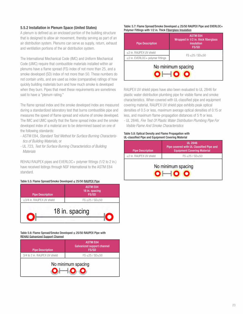
5.5.2 Installation in Plenum Space (United States)Aplenumisdefinedasanenclosedportionofthebuildingstructurethatisdesignedtoallowairmovement,therebyservingaspartofanairdistributionsystem.Plenumscanserveassupply,return,exhaustandventilationportionsoftheairdistributionsystem.
TheInternationalMechanicalCode(IMC)andUniformMechanicalCode(UMC)requirethatcombustiblematerialsinstalledwithinairplenumshaveaflamespread(FS)indexofnotmorethan25,andasmokedeveloped(SD)indexofnotmorethan50.Thesenumbersdonotcontainunits,andareusedasindex(comparative)ratingsofhowquicklybuildingmaterialsburnandhowmuchsmokeisdevelopedwhentheyburn.Pipesthatmeettheserequirementsaresometimessaidtohavea"plenumrating."
Theflamespreadindexandthesmokedevelopedindexaremeasuredduringastandardizedlaboratorytestthatburnscombustiblepipeandmeasuresthespeedofflamespreadandvolumeofsmokedeveloped.TheIMCandUMCspecifythattheflamespreadindexandthesmokedevelopedindexofamaterialaretobedeterminedbasedononeofthefollowingstandards:-ASTME84,Standard Test Method for Surface Burning Characteris-
tics of Building Materials, or-UL723, Test for Surface Burning Characteristics of Building
Materials
REHAURAUPEXpipesandEVERLOC+polymerfittings(1/2to2in.)havereceivedlistingsthroughNSFInternationaltotheASTME84standard.
Table 5.5: Flame Spread/Smoke Developed ≤ 25/50 RAUPEX Pipe
Pipe Description
ASTM E84 18 in. spacing
FS/SD
≤3/4in.RAUPEXUVshield FS≤25/SD≤50
Table 5.6: Flame Spread/Smoke Developed ≤ 25/50 RAUPEX Pipe with REHAU Galvanized Support Channel
Pipe Description
ASTM E84 Galvanized support channel
FS/SD
3/4to2in.RAUPEXUVshield FS≤25/SD≤50
Table: 5.7: Flame Spread/Smoke Developed ≤ 25/50 RAUPEX Pipe and EVERLOC+ Polymer Fittings with 1/2 in. Thick Fiberglass Insulation
Pipe Description
ASTM E84 Wrapped in 1/2 in. thick fiberglass
insulation FS/SD
≤2in.RAUPEXUVshieldFS≤25/SD≤50
≤2in.EVERLOC+polymerfittings
RAUPEXUVshieldpipeshavealsobeenevaluatedtoUL2846forplasticwaterdistributionplumbingpipeforvisibleflameandsmokecharacteristics.WhencoveredwithUL-classifiedpipeandequipmentcoveringmaterial,RAUPEXUVshieldpipeexhibitspeakopticaldensitiesof0.5orless,maximumaverageopticaldensitiesof0.15orless,andmaximumflame-propagationdistancesof5ftorless.-UL2846,Fire Test Of Plastic Water Distribution Plumbing Pipe For
Visible Flame And Smoke Characteristics
Table 5.8: Optical Density and Flame Propagation with UL-classified Pipe and Equipment Covering Material
Pipe Description
UL 2846Pipe covered with UL Classified Pipe and
Equipment Covering Material
≤2in.RAUPEXUVshield FS≤25/SD≤50
23
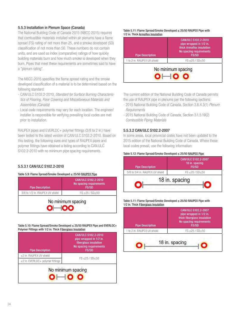
5.5.3 Installation in Plenum Space (Canada)TheNationalBuildingCodeofCanada2015(NBCC-2015)requiresthatcombustiblematerialsinstalledwithinairplenumshaveaflamespread(FS)ratingofnotmorethan25,andasmokedeveloped(SD)classificationofnotmorethan50.Thesenumbersdonotcontainunits,andareusedasindex(comparative)ratingsofhowquicklybuildingmaterialsburnandhowmuchsmokeisdevelopedwhentheyburn.Pipesthatmeettheserequirementsaresometimessaidtohavea"plenumrating".
TheNBCC-2015specifiestheflamespreadratingandthesmokedevelopedclassificationofamaterialistobedeterminedbasedonthefollowingstandard:-CAN/ULCS102.2-2010,Standard for Surface Burning Characteris-
tics of Flooring, Floor Covering and Miscellaneous Materials and Assemblies (Canada)-Localcoderequirementsmayvaryforeachlocation.Theengineer/installerisresponsibleforverifyingprevailinglocalcodesaremetprior to installation.
RAUPEXpipesandEVERLOC+polymerfittings(3/8to2in.)havebeentestedtothelatestversionofCAN/ULCS102.2-2010.Basedonthistesting,thefollowingsizesandtypesofRAUPEXpipesandpolymerfittingshaveobtainedalistingaccordingtoCAN.ULCS102.2-2010withnominimumpipespacingrequirements.
5.5.3.1 CAN/ULC S102.2-2010
Table 5.9: Flame Spread/Smoke Developed ≤ 25/50 RAUPEX Pipe
Pipe Description
CAN/ULC S102.2-2010No spacing requirements
FS/SD
3/8to1/2in.RAUPEXUVshield FS≤25/SD≤50
Table 5.10: Flame Spread/Smoke Developed ≤ 25/50 RAUPEX Pipe and EVERLOC+ Polymer Fittings with 1/2 in. Thick Fiberglass Insulation
Pipe Description
CAN/ULC S102.2-2010pipe wrapped in 1/2 in.
fiberglass insulationNo spacing requirements
FS/SD
≤2in.RAUPEXUVshieldFS≤25/SD≤50
≤2in.EVERLOC+polymerfittings
Table 5.11: Flame Spread/Smoke Developed ≤ 25/50 RAUPEX Pipe with 1/2 in. Thick Armaflex Insulation
Pipe Description
CAN/ULC S102.2-2010pipe wrapped in 1/2 in.
thick Armaflex insulation No spacing requirements
FS/SD
1to2in.RAUPEXUVshield FS≤25/SD≤50
ThecurrenteditionoftheNationalBuildingCodeofCanadapermitstheuseofRAUPEXpipeinplenumsperthefollowingsections:-2015NationalBuildingCodeofCanada,Section3.6.4.3(1)Plenum
Requirements-2015NationalBuildingCodeofCanada,Section3.1.5.19(2)
Combustible Piping Materials
5.5.3.2 CAN/ULC S102.2-2007Insomeareas,localprovincialcodeshavenotbeenupdatedtothe2015editionoftheNationalBuildingCodeofCanada.Wheretheselocalcodesprevail,usethefollowinginformation:
Table 5.12: Flame Spread/Smoke Developed ≤ 25/50 RAUPEX Pipe
Pipe Description
CAN/ULC S102.2-200718 in. spacing
FS/SD
3/8to3/4in.RAUPEXUVshield FS≤25/SD≤50
Table 5.11: Flame Spread/Smoke Developed ≤ 25/50 RAUPEX Pipe with 1/2 in. Thick Fiberglass Insulation
Pipe Description
CAN/ULC S102.2-2007pipe wrapped in 1/2 in.
thick fiberglass insulation No spacing requirements
FS/SD
1to2in.RAUPEXUVshield FS≤25/SD≤50
24

5.6 Overhead InstallationsSuspendedsectionsofPEXpipeneedtobeinstalledusingmethodstoensurethepipedoesnotsag.StandardCopperTubeSize(CTS)hangers,includingclevisandloophangers,canbeusedtosupportsuspendedsectionsofPEXpipe.
Thehangersystemmustbestrongenoughtosupportthepipeanditscontents.AllsupportsthatcomeincontactwithRAUPEXpipemustbeapprovedmaterialsthatarecompatiblewiththepiping.
RAUPEXwillexpandandcontractwhenheatedandcooled.Itisimportanttoincorporatethiswhendesigningpathwaysandsupports.RAUPEXmaybesupportedusingeitherafixedpointorslidingsupportdevice.Fixedsupportpoints,suchaslockingclips,talondrivehooksandsinglenailclamps,willrigidlyholdRAUPEXinplaceandminimizethemovementofthepipeduringexpansionorcontraction.ThesearetypicallyinstalledonbothsidesofEVERLOC+fittinglocations.Slidingsupportdevices,liketheisolatingsuspensionclamps,willpermitthepipetoslidewithinthesupportduringexpansionandcontraction.
Whenchoosingsupports,ensuretheywillnotcut,scratchordamagethepipe.Ifusingmetalsupports,makesuretherearenosharpedgesthatcoulddamagethepipe.
RAUPEXpipe3/8to1in.diametermustbesupportedwithamaximumspacingof32in(80cm)horizontallyand10ft(3m)vertically.RAUPEXpipelargerthan1in.diametermustbesupportedwithamaximumspacingof48in(120cm)horizontallyand10ft(3m)vertically.Alwayscomplywiththeprevailinglocalcodeforsupportspacingintervals.
REHAUgalvanizedsteelsupportchannelcanbeusedtogaingreaterspacingbetweensupporthangers.ThegalvanizedsteelsupportchannelisspecificallydesignedtosupportREHAURAUPEXpipeinsizes3/4to2in.
TheprofileofthegalvanizedsupportchannelismadesotheRAUPEXpipewillsnapintothesupportchannelwithoutrequiringadditionalfasteningmethodstoholdthepipeinplace.Theresultisarigidpipematrixwithadequatestiffnesstobesupportedinoverheadandexposedapplications.Thepipematrixissupportedusingtypicalmechanicalclevishangersspacedsimilartometallicpipeinstallations.Allpiecesofgalvanizedsteelsupportchannelmusthaveaminimumoftwosupports/hangers.
-Extendsupportaminimumof1in(25mm)pasthanger-EnsureadequateRAUPEXoverhangpastsupportchanneltoallowinstallationofEVERLOC+fitting,ifrequired-Use3/8in.threadedrodtosuspendthesupportchannelwithamaximumspacingbetweensupportsof8ft(2.4m).
Note:Alwayscomplywiththeprevailinglocalcodesforsupportspacingintervals.
Fig. 5.6: REHAU galvanized steel Fig. 5.7: RAUPEX pipe in overhead installation
support channel
5.7 Water QualityRAUPEXpipeandEVERLOC+compression-sleevefittingsarethird-partytestedandcertifiedforusewheredrinkingwaterqualitiesmeettherequirementsoftheEPANational Primary Drinking Water RegulationsandtheGuidelines for Canadian Drinking Water Quality byHealthCanada.
TheU.S. Safe Drinking Water Actandthe Lead and Copper Rule requirepublicwatersupplierstoprovidenon-corrosivedrinkingwatertocustomers.However,irrespectiveofthematerialused,inrareandisolatedcases,corrosioncanoccurevenwhenthewaterqualitylevelsarewithinthepermissiblerangesetforthbytheEPANational Primary Drinking Water Standards andtheGuidelines for Canadian Drinking Water QualitybyHealthCanada.Someinfluenc-ingfactorsoncorrosionbehaviorarewaterdisinfectionprocesses,pHlevels,chloridecontent,sulfatecontentandtheuseofanin-housewatertreatmentsystem.
Toevaluatetheprobabilityofcorrosionforplumbingcomponentsinapotablewatersystem,thelicensedinstallingcontractormusthavepracticalexperiencewithinthegeographicregionofintendeduse.Consultationwiththelocalplumbingauthorityandlocalwaterauthorityregardingtheseexperiencesshouldoccurbeforetheselectionandinstallationofpotableplumbingcomponents.
Thecorrosivityofwaterdependsonamultitudeofinterdependentvariablesandtherearenosimpleequationsorindicesforpredictingthecorrosionpotential.Itmustbeunderstoodthatcorrosionisaphenomenonassociatedwiththebehaviorofsystemcomponentsintheiroperatingenvironment.Everymaterialhasauniquetendencytocorrodeornotcorrodeinasimilarenvironment.However,withlocalknowledgeofspecificwatercharacteristicsandtheenvironmentinwhichthesystemcomponentsareinstalled,thedesignengineerandinstallingcontractorcanmakepropermaterialselectionsanddeterminepropersystemoperatingparameterstominimizethepotentialforcorrosionofthepipingsystem.
25

Iflocalconditionsareknowntocausecorrosionissues,awaterqualityexpertwithcorrosionexperienceshouldbeconsulted.
InorderfortheREHAU PEXa Limited Warranty toapply,productsmustnotbesubjectedtodamageorwearcausedbyabnormaloperatingconditionsandtheproductsmustnotbeexposedtoharmfulchemicals,aggressivewaterconditionsoranyexternalinfluencesthatcausedamagetotheproducts.
5.8 Hot Water RecirculationBenefitsofhotwaterrecirculation:-Reducesthetimeyouhavetowaittodeliverhotwatertofixturesthatarefarfromthehotwaterstoragetank,whichreduceswaterwaste-HelpspreventstagnantsystemconditionsinthepipingnetworkthatcanallowforLegionellabacteriagrowth
Plumbingfixturesthatrequirehotwaterarenotalwayslocatedincloseproximitytothehotwaterstoragetank.Hotwaterrecirculationsystemscirculatehotwaterthroughoutthebuildingandbacktothestoragetanktomaintainwarmerwatertemperaturesclosertothehotwaterfixtures.Thesesystemsaimtoreducethewaittimeforhotwaterateachfixture.
InordertomeettherequirementsoftheInternationalPlumbingCodeSection607.2:-607.2, Hot or tempered water supply to fixtures.Thedevelopedlengthofhotortemperedwaterpiping,fromthesourceofhotwatertothefixturesthatrequirehotortemperedwater,shallnotexceed50ft(15m).Recirculatingsystempipingandheat-tracedpipingshallbeconsideredtobesourcesofhotortemperedwater.-607.2.1,Circulation systems and heat trace systems for maintaining
heated water temperature in distribution systems.ForGroupR2,R3andR4occupanciesthatarethreestoriesorlessinheightabovegradeplane,theinstallationofheatedwatercirculationandtemperaturemaintenancesystemsshallbeinaccordancewithSectionR403.5.1oftheInternationalEnergyConservationCode.
Aproperlycontrolledhotwaterrecirculationsystemwithwell-insulat-edpipingiskeytomeetcoderequirementsandavoidexcessenergyuse.Tominimizeenergywaste,domesticrecirculationpumpcontrolsareimportant.Energycanbesavedwithrecirculationpumpcontrols:-Simpletimercontrolsoroccupancysensorsthatonlyrecirculatehotwaterwhenthebuildingisoccupied- Temperature-basedcontrols,typicallyanaquastat,thatturnonthepumpwhenthetemperaturedropsbelowacertainthresholdcanfurtherassistintherecirculationloop.
-Pressure-changebasedcontrolsthatonlyspeedupwhenthedemandforhotwaterincreases
5.8.1 Legionella ConsiderationsAccordingtotheCenterforDiseaseControlandPrevention,Legionellaisatypeofbacteriumfoundnaturallyinfreshwaterenvironments,likelakesandstreams.Itcanbecomeahealthconcernwhenitgrowsandspreadsinhuman-madewatersystems.Thebacteriacanmultiplyinwarm,stagnantwaterandaffectshumanswhendropletsofwatercontaininghighconcentrationsofthebacterialareinhaled.Thebacteriabeginstodiewhenthewatertemperatureiselevatedabove120°F(50°C),butthedisinfectionismoreeffectiveathighertemperatures.(www.osha.gov/dts/osta/otm/legionnaires/faq.html)
Domestichotwatersystemdesignisusefultopreventthegrowthofthisbacteriawiththesetwomethods:-Minimizingdead-legdistances(thevolumeofwaterthatisbetweeneitherahotwaterstoragetankorarecirculationlineandthefixture)iscrucialtosystemdesign.Whilethe2015IPC Section 607.2mayallowforupto50ft(15m)ofpipebetweenthesetwopoints,reducingthatdistancewillreducethevolumeofwaterthatcanstagnateifthefixtureisunusedforalongperiodoftime.Stagnatewaterthatisn’tregularlythermallydisin-fectedmayallowLegionellabacteriatogrow.-Increasingthetemperatureofthewaterspeedsupthethermaldisinfec-tiontimeofLegionellabacteria.Youmustalsoavoidscaldingrisksassociatedwithmaximumdeliverablewatertemperaturesforoccupants,determinedbytheauthorityhavingjurisdiction.
Thereisn’tacomponentmanufacturerorportionofaplumbingsystemthatbearsalltheresponsibilityforLegionellagrowthprevention.ThePlasticsPipe Institute Recommendation Against Mixing Hydronic Heating Water with Potable Water, Recommendation E, 2016isagoodsourcefornon-manu-facturerspecificLegionellaconcerns.
5.9 Water HammerWaterhammer,alsocalledhydraulicshock,commonlyoccurswhenavalveclosessuddenlyattheendofapipelinesystem,andapressurewavepropagatesinthepipe,creatingvibrationandnoise.
Whilethesestatementsmaybetrueformetallicpipingsystems,theabilityofPEXpipetoabsorbshockeliminatestheneedforwaterhammerarresters,ifallowedbyprevailinglocalcodes.
26
6. INSTALLATION CONSIDERATIONS
6.1 Local Code ApprovalsTheinstallationoftheREHAUPEXaplumbingsystemforuseindomesticplumbingsystemsmustbeinaccordancewiththeguide-linesthatarepresentedinthistechnicalguide.Prevailinglocalcodeswherethesystemisbeinginstalledmustbeobserved.Wherelocalcodeandthistechnicalguideconflicteachother,localcodeshouldprevail.However,itistheresponsibilityofthedesignerandinstallertodiscussanyvariationwithREHAUEngineeringtoensureanyvariationwillnotadverselyaffecttheperformance,operationorlifeexpectancyofthesystemanditscomponents.
6.2 Packaging, Transport, Handling and Storage
6.2.1 RAUPEX Pipe PackagingRAUPEXpipecoilsareshippedincardboardboxestoprotectthemfromsunlight,rain,dirtandotherhazards.StraightlengthsofRAUPEXpipearepackagedandshippedinblackpolyethylenebags.Keeppipeintheoriginalpackaginguntilitisrequiredforinstallation.Returnunusedpipetothepackaging.
Avoidthefollowing:-Draggingpipeoverroughobjects-Contactofpipewithpetroleumproductssuchasoil,gasoline,paintthinner-Exposureofpipetosolderingoranyopenflame-Excessiveorpermanentexposuretosunlight
6.2.2 EVERLOC+ Fittings PackagingEVERLOC+fittingsandsleevesareshippedincardboardboxestoprotectthemfromsunlight,rain,dirtandotherhazards.Keeptheproductsintheoriginalpackaginguntiltheyarerequiredforinstalla-tion.Returnunusedproductstothepackagingforstorage.
Fittingsandsleevesmustbehandledwithcare.Ataminimum,avoidthefollowing:-Storingloosefittingsintoolboxes-Contactwithoiloroilyproductssuchasgasoline,paintthinner,gluesorsolvents-ExposureofpolymerfittingsandPEXasleevestosolderingoranyopenflame-ExcessiveorpermanentexposuretosunlightofpolymerfittingsandPEXasleeves
6.3 Uncoiling PipeForbestresultswheninstallingRAUPEXpipefromacoil,useaREHAUapproveduncoilingdevice.Thiswillallowthepipetolayflat(nottwisted)wheninstalled.Twistingthepipemayplacestressonthepipeafterinstallation.
RAUPEXmaybetakenfromacoilwithouttheuseofanuncoilingdevice.Whenusingthismethod,besuretorollthepipefromthecoil.Donotlaythecoilflatonitssideandpullthepipeupoverthesideofthecoilasthiswilltwistthepipe.
Fig. 6.1: Uncoiling RAUPEX pipe
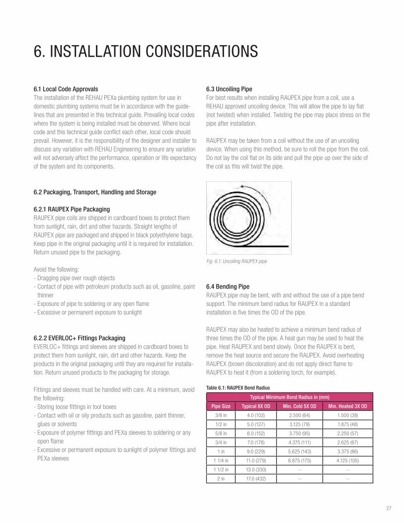
6.4 Bending PipeRAUPEXpipemaybebent,withandwithouttheuseofapipebendsupport.TheminimumbendradiusforRAUPEXinastandardinstallationisfivetimestheODofthepipe.
RAUPEXmayalsobeheatedtoachieveaminimumbendradiusofthreetimestheODofthepipe.Aheatgunmaybeusedtoheatthepipe.HeatRAUPEXandbendslowly.OncetheRAUPEXisbent,removetheheatsourceandsecuretheRAUPEX.AvoidoverheatingRAUPEX(browndiscoloration)anddonotapplydirectflametoRAUPEXtoheatit(fromasolderingtorch,forexample).
Table 6.1: RAUPEX Bend Radius
Typical Minimum Bend Radius in (mm)
Pipe Size Typical 8X OD Min. Cold 5X OD Min. Heated 3X OD
3/8in 4.0(102) 2.500(64) 1.500(38)
1/2in 5.0(127) 3.125(79) 1.875(48)
5/8in 6.0(152) 3.750(95) 2.250(57)
3/4in 7.0(178) 4.375(111) 2.625(67)
1 in 9.0(229) 5.625(143) 3.375(86)
11/4in 11.0(279) 6.875(175) 4.125(105)
11/2in 13.0(330) -- --
2 in 17.0(432) -- --
27
Bend Radius90
Fig. 6.2: Bend radius of RAUPEX pipe
6.5 Distance Between Fittings AminimumdistancebetweenEVERLOC+fittingsisrequiredtoensurethefittingsarenotdamagedduringtheexpansionprocessbytheinstallationtools.Aminimumpipelengthof3timesthelengthofsleeveisrequiredbetweenfittingsforproperinstallation.
A3A
EVERLOC+ PEXaCompression Sleeve
RAUPEX Pipe
EVERLOC+ Fitting
Fig. 6.3: Required minimum distance between fittings
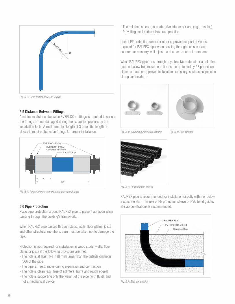
6.6 Pipe ProtectionPlacepipeprotectionaroundRAUPEXpipetopreventabrasionwhenpassingthroughthebuilding'sframework.
WhenRAUPEXpipepassesthroughstuds,walls,floorplates,joistsandotherstructuralmembers,caremustbetakennottodamagethepipe.
Protectionisnotrequiredforinstallationinwoodstuds,walls,floorplatesorjoistsifthefollowingprovisionsaremet:-Theholeisatleast1/4in(6mm)largerthantheoutsidediameter(OD)ofthepipe-Thepipeisfreetomoveduringexpansionandcontraction-Theholeisclean(e.g.,freeofsplinters,burrsandroughedges)-Theholeissupportingonlytheweightofthepipe(withfluid),andnotamechanicaldevice
-Theholehassmooth,non-abrasiveinteriorsurface(e.g.,bushing)-Prevailinglocalcodesallowsuchpractice
UseofPEprotectionsleeveorotherapprovedsupportdeviceisrequiredforRAUPEXpipewhenpassingthroughholesinsteel,concreteormasonrywalls,joistsandotherstructuralmembers.
WhenRAUPEXpiperunsthroughanyabrasivematerial,oraholethatdoesnotallowfreemovement,itmustbeprotectedbyPEprotectionsleeveoranotherapprovedinstallationaccessory,suchassuspensionclampsorisolators.
Fig. 6.4: Isolation suspension clamps Fig. 6.5: Pipe isolator
Fig. 6.6: PE protection sleeve
RAUPEXpipeisrecommendedforinstallationdirectlywithinorbelowaconcreteslab.TheuseofPEprotectionsleeveorPVCbendguidesatslabpenetrationsisrecommended.
Fig. 6.7: Slab penetration
28

6.7 InsulationThermalconductivityofRAUPEXpipeismuchlowerthanthatofmetallicpipes.Insulationcanbeinstalledtofurtherenhancethisproperty,todecreaseenergyusage,andmaintainwatertemperatureinsidethepipe.BecauseofthethermalpropertiesofRAUPEXpipe,itisalsolesssusceptibletocondensationorsweatingoncoldwaterlines.
Insulationcanbeinstalledoncoldwaterlinestoimproveresistancetocondensationorbettermaintaininternalwatertemperature.Alwayscomplywithprevailinglocalcodes.
6.8 Installation Below-grade, in-slabRAUPEXmaybeinstalleddirectlywithinorbelowaconcreteslab.Thisisespeciallyusefulinslab-on-gradeconstruction.RAUPEXpipesencasedwithinconcreteslabsarenotrequiredtobesleeved.
ToprotectRAUPEXpipefromabrasionwhereitpassesthroughtheconcrete,theuseofPEprotectionsleevesorPVCbendguidesatallslabpenetrationsisrecommended.
ContinuoussleevingofRAUPEXplumbingpipesburiedbeloworwithinaconcreteslabisnotprohibited,however,insuchcasesthefollowingprecautionmustbefollowed:-WhenRAUPEXpipesarecontinuouslysleevedbeloworaboveaslab,thespacebetweenthepipeandthesleevingmustneverbefilledwithanyliquidchemical,includingpesticidesortermiticides.-Theannulargapbetweenthepipesattheendsshouldbefilledwithsiliconeorpolyurethaneexpandingfoamtohelppreventpathwaysforpestsandthemistakenapplicationofharmfulchemicalsintothespacebetweenthepipeandthesleeving.-UseonlysealantsthatarecompatiblewithRAUPEXpipe.
WARNING-ApplicationofpesticidesortermiticidesbetweenRAUPEXpipeandsleevingisstrictlyprohibited.Permeationofpesticidesortermiticidesmayoccurthroughthepipewallresultinginseriousinjuryordeath.-RAUPEXpipesforplumbingapplicationsshallnotbeinstalledincontaminatedsoilsorimmersedinliquidchemicals.Donotdirectlysprayonoralloworganic(petroleum-based)chemicalssuchas,petroleumdistillates,termiticidesorpesticidestocomeintocontactwithRAUPEXpipes.Permeationoftheseharmfulchemicalsmayoccurthroughthepipewallresultinginseriousinjuryordeath.
Fig. 6.8: Continuous sleeve installation
Fig 6.9: Slab penetration protection
ApressuretestonRAUPEXpipesbeforeencasinginconcreteisrecommendedtoensureRAUPEXpipeandconnectionsareleakfree.Installersshouldmaintaintestpressureonthesystemduringfurtherconstruction,wherepractical.Airtestingispermitted.Ifawater(hydrostatic)testisused,thewatermustbeprotectedfromfreezing.DetailedpressuretestingprocedureisoutlinedinSection6.17.2.
6.9 Fixture Connection Common Components
6.9.1 Drop Ear ElbowsTheEVERLOC+LFbrassdropearelbowprovidesarigid90°bendandtheabilitytosecure1/2or3⁄4in.RAUPEXpipewhereitexitsastudwallorconnectstoashowerhead. Fig. 6.10: Drop ear elbow
6.9.2 Copper Ells TheEVERLOC+tub/showerdiverterellprovidesa90°transitionfromtubandshowervalvetoRAUPEXpipe.
TheEVERLOC+closed-endstuboutellprovidesa90°transitionfromRAUPEXpipetocopper.Useclosed-endstuboutellsatthefixturetoexitfromthewall.
29
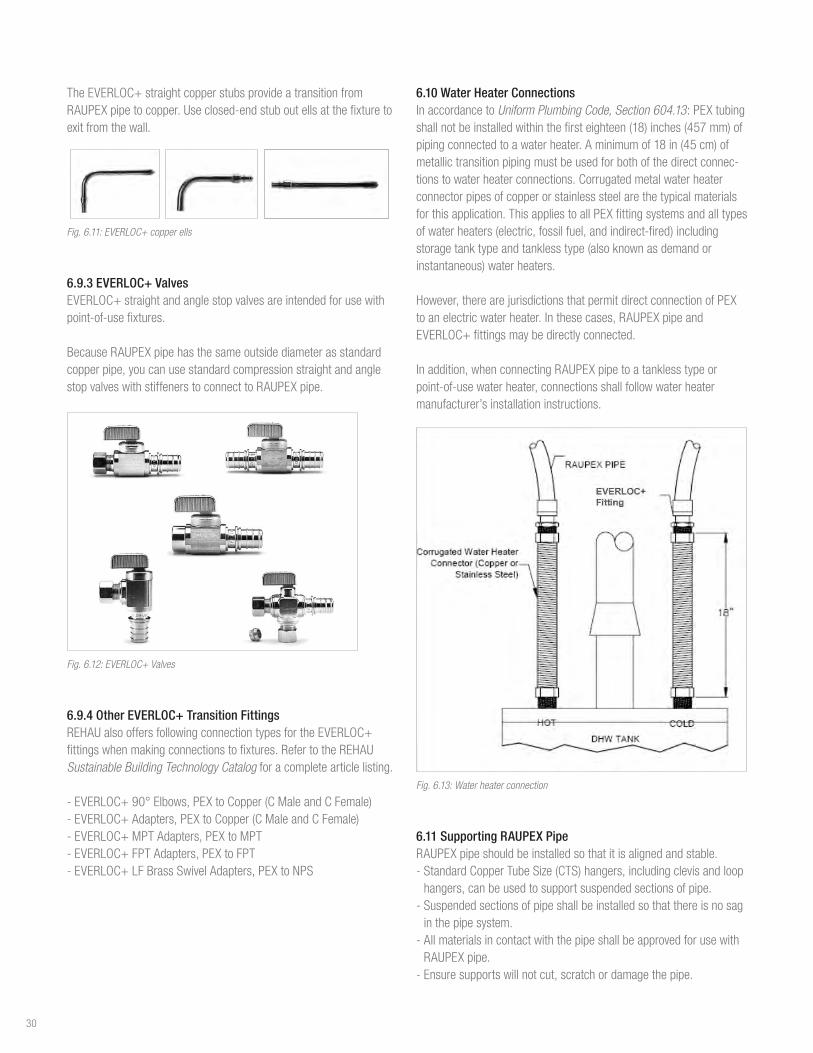
TheEVERLOC+straightcopperstubsprovideatransitionfromRAUPEXpipetocopper.Useclosed-endstuboutellsatthefixturetoexitfromthewall.
Fig. 6.11: EVERLOC+ copper ells
6.9.3 EVERLOC+ ValvesEVERLOC+straightandanglestopvalvesareintendedforusewithpoint-of-usefixtures.
BecauseRAUPEXpipehasthesameoutsidediameterasstandardcopperpipe,youcanusestandardcompressionstraightandanglestopvalveswithstiffenerstoconnecttoRAUPEXpipe.
Fig. 6.12: EVERLOC+ Valves
6.9.4 Other EVERLOC+ Transition FittingsREHAUalsooffersfollowingconnectiontypesfortheEVERLOC+fittingswhenmakingconnectionstofixtures.RefertotheREHAU Sustainable Building Technology Catalogforacompletearticlelisting.
-EVERLOC+90°Elbows,PEXtoCopper(CMaleandCFemale)-EVERLOC+Adapters,PEXtoCopper(CMaleandCFemale)-EVERLOC+MPTAdapters,PEXtoMPT-EVERLOC+FPTAdapters,PEXtoFPT-EVERLOC+LFBrassSwivelAdapters,PEXtoNPS
6.10 Water Heater Connections In accordance to Uniform Plumbing Code, Section 604.13:PEXtubingshallnotbeinstalledwithinthefirsteighteen(18)inches(457mm)ofpipingconnectedtoawaterheater.Aminimumof18in(45cm)ofmetallictransitionpipingmustbeusedforbothofthedirectconnec-tionstowaterheaterconnections.Corrugatedmetalwaterheaterconnectorpipesofcopperorstainlesssteelarethetypicalmaterialsforthisapplication.ThisappliestoallPEXfittingsystemsandalltypesofwaterheaters(electric,fossilfuel,andindirect-fired)includingstoragetanktypeandtanklesstype(alsoknownasdemandorinstantaneous)waterheaters.
However,therearejurisdictionsthatpermitdirectconnectionofPEXtoanelectricwaterheater.Inthesecases,RAUPEXpipeandEVERLOC+fittingsmaybedirectlyconnected.
Inaddition,whenconnectingRAUPEXpipetoatanklesstypeorpoint-of-usewaterheater,connectionsshallfollowwaterheatermanufacturer’sinstallationinstructions.
Fig. 6.13: Water heater connection
6.11 Supporting RAUPEX PipeRAUPEXpipeshouldbeinstalledsothatitisalignedandstable.-StandardCopperTubeSize(CTS)hangers,includingclevisandloophangers,canbeusedtosupportsuspendedsectionsofpipe.-Suspendedsectionsofpipeshallbeinstalledsothatthereisnosaginthepipesystem.-AllmaterialsincontactwiththepipeshallbeapprovedforusewithRAUPEXpipe.-Ensuresupportswillnotcut,scratchordamagethepipe.
30

-Suspendedinstallationsinwood-frameconstructioncanutilizestrutchannelhangingwithall-threadasthesupportdevicewiththeappropriateclampstosecurepipetothestrut.Whenclampingpipe,besurenottodeformthepipewiththeforceoftheclamp.-Installationsinsteel-frameconstructioncanbedonesimilarly,butcanalsousebeamclampstosecuretheall-threadtosteelI-Beams.-Steeljoistspacecanbeusedasthesupportmethod.
Whennotinstallinginsuspension,othersupportmechanismsforRAUPEXpipecanbeused.Theseincludesinglenailhooks,pipesupportbends,talondrivehooksandlockingclips.Thesecanalsobeusedforsmallerbranchrunsofpipeaswellastoassistinmakingbendstoconnecttofixtures.
RAUPEXpipe3/8to1in.diametermustbesupportedwithamaximumspacingof32in(80cm)horizontallyand10ft(3m)vertically.RAUPEXpipelargerthan1in.diametermustbesupportedwithamaximumspacingof48in(120cm)horizontallyand10ft(3m)vertically.Alwayscomplywiththeprevailinglocalcodeforsupportspacingintervals.
Fig. 6.14: Single nail hooks Fig. 6.15: Pipe support bend
Fig. 6.16: Talon drive hooks Fig 6.17: Locking clip
6.11.1 Galvanized Steel Support ChannelREHAUgalvanizedsteelsupportchannelisdesignedtosupportRAUPEXpipe,minimizespipeexpansionandreducestheamountofCTSsupports.TheprofileofthegalvanizedsupportchannelisdesignedsotheRAUPEXpipewillsnapinwithoutrequiringadditionalfasteningmethodstoholdthepipeinplace.
Thesupportchannelcanbecuttomeetinstallationrequirementsusingpowertoolssuchasabandsaworhandtools.Whencutting,besurenottobendoraltertheoverallprofileofthechannel.Aftercuttingthechannel,besuretoremoveanysharpedgesorburrstopreventdamagetotheRAUPEXpipe.
Typicalmechanicalclevishangerscanbeusedforsupport,andtheslimprofileofthechannelallowsstandardCTSinsulationtobeinstalledaroundit.InstallingRAUPEXpipeintothesupportchannelbeforesuspendingtheassemblyisrecommended.Iffittingswillneedtobeinstalledin-linewiththerunofpipeinthesupportchannel,besuretohavetheRAUPEXpipeoverhangtheendofthesupportchannelatleasttwoEVERLOC+sleevelengths.Additionally,thegalvanizedsteelsupportchannelshallextendaminimumof1in.(2.5cm)pastthehanger.
Use3/8in.threadedrodtosuspendthesupportchannelwithamaximumspacingbetweensupportsof8ft(2.4m).Alwayscomplywithprevailinglocalcodesforsupportspacingintervals.
Fig. 6.18: RAUPEX pipe supported with steel support channel
6.12 Supporting EVERLOC+ FittingsSupportsandclampsshallnotbeplaceddirectlyontheEVERLOC+fitting,multi-portteeorcompressionsleeve.Alwayscomplywithprevailinglocalcodes.
6.13 Copper SolderingPropersolderingtechniquesmustbefollowedwhensolderingallcompression-sleevefittingsaccordingtotheCopperDevelopmentAssociation(CDA)Handbook:-Thesurfaceofthefittingsolderingareamustbeproperlycleanedforagoodsolderconnection.Applyingfluxisnotconsideredsufficientcleaningforthesolderingarea.Usingapropersandingorbrushtechniqueisnecessarytoremovethesurfaceoxides.Inordertopreventfurtherformationofoxides,thefluxshouldbeappliedimmediatelyafterthecleaningprocess.Aproperfluxthatiscompatiblewiththebrassalloymustbeused.
31

-Caremustbetakentonotoverheatthesolderingsurfaceasthiscanleadtotheformationofoxidespreventinggoodadhesionofthesoldermaterial.Itisimperativethatthefittingisheatedevenlyaroundtheentiresurfacesoastonotoverheatoneparticulararea.-Allcompletedsolderjointsmustbetestedforjointintegrityfollowingtheproceduresprescribedbyprevailinglocalcodes.
WhensolderinganEVERLOC+LFbrassfitting:-Thefittingmustbesolderedontothecopperfirst.-Thesolderjointmustbeallowedtocooltoambientroomtempera-turepriortomakinganEVERLOC+connection.
Fig. 6.19: Solder prior to making EVERLOC+ connection
Fig. 6.20: Never solder after EVERLOC+ connection has been made
WARNING - Useglovesandaholdingtool.Heatedpipeandfittingscancauseburns. - Neveruseatorch,openflameorheatgunonapressurizedsystem.Exceedingthetemperaturepressureratingswillresultindangerousseparationofmaterialsleadingtoseriousinjuryordeath. - Neverreworkaconnectionthatisunderpressure.Depressurizethesystem,cutoutconnectionandreplace
6.14 Kink RepairRAUPEXpipeisflexibleandresistskinkingevenattemperatureswellbelowfreezing.Ifthepipedoesbecomekinked,flowmaybeobstructedorreduced.Kinkedpipemustberepaired.
Straightenthepipebyheatingtheareawithaheatgun,rotatingtheheatgunaroundthepipetoevenlyheatthesurface.Alwaysusecautionwhenoperatingaheatgunandneveruseatorchoropenflametoheatthepipe.
Whenfullyheated,thepipewillbecometransparent.Whenthekinkisgone,turnofftheheatgunandlettheareacool.(Itisnormalforsmallbubblesorwrinklestoappear.)Thistypeofheatingwillannealorstiffenthepipe,makingitstrongerbutalsolessflexibleintheheatedarea.Therefore,donottrytobendthepipeinthesamespot.Thismayrequireaslightadjustmentoffasteners.
6.15 Thawing Frozen PipeWhenconditionsoccurthatallowwatertofreezeinsidethepipe,theflexibilityofRAUPEXallowsthepipetoexpandaswaterfreezes,aslongasthepipehasroomtoexpand.
Whenthewaterthaws,thepipereturnstoitsoriginalshape.Ifthepipeisnotallowedtoexpand(e.g.,itisencasedinconcrete),itmayburst.Iffreezingdoesoccur,thefollowingmethodscanbeusedtothawthefrozensection:-Heatthefrozenareawithaheatgun.Besurenottoconcentrateexcessiveheatinasingleareafortoolong-Wraptowelsaroundthepipingandpourhotwateronthetowels-Useaspaceheatertowarmtheroomuntilthefrozensectionthaws
WhiletheflexibilityoftheRAUPEXpipeallowsittoexpandaswaterfreezesinthepipe,thisflexibilitydoesnotensuretheintegrityofthejoint.Installersmusttakeprecautionstoensurethatpipesandfittingsdonotfreeze.Thismayresultinleaksandoperationalfailures.
6.16 DisinfectionDisinfectionofthesystemshouldalwaysfollowprevailinglocalcodesandrequirements.Ifrequiredbycodeandnoconditionsarespecified,disinfectusingchlorinationaccordingtoAWWAorICCproceduresoutlinedbelow:
Table 6.2: AWWA/ICC Disinfection Schedule
Chlorine Concentration Disinfection Period Authority
50to100ppm 3hours AWWA
50ppm 6hours ICC
Pre-mixsolutionbeforeinjectingintosystem.Donotallowdisinfectionsolutiontositinsystembeyondthedisinfectionperiod.Thoroughlyflushentiresystemwithpotablewaterafterdisinfection.
32
6.17 Pressure TestingREHAUhasadetailedpressuretestprocedurefortestingaREHAUPEXapipingsystemassetforthbelow.
WARNING - Failuretofollowpropersafetyprecautionsforanairpressuretestcouldresultindangerousseparationofthematerial,leadingtoseriousinjuryordeath. - Usepersonalprotectiveequipment.Toreducetheriskofeyeinjury,alwayswearclose-fittingprotectiveeyewearwithsideprotection.Eyewearmustbeimpact-ratedandmarkedascomplyingwithANSIZ87.1. - Neveruseatorch,openflameorheatgunonapressurizedsystem.Exceedingthetemperaturepressureratingswillresultindangerousseparationofmaterialsleadingtoseriousinjuryordeath. - Neverreworkaconnectionthatisunderpressure.Depressurizethesystem,cutoutconnectionandreplace. - Toreducetheriskofpersonalinjury,onlyqualifiedpersonsconductingand/orinspectingthepressuretestshouldbepresent.
Thefollowingrecommendedpressuretestprocedureappliestobothcompressedairandhydrostatic(water)testing:
6.17.1 General Recommendations - Apressuretestmustalwaysbeperformedpriortoclosinginthesystem(e.g.,behinddrywall). - Performtestusingwaterorairatambienttemperature.Donotexceed150psi(1030kPa)forthepipingsystem.Verifymaximumpressurelimitsarenotexceededforallsystemcomponentspriortoperformingthepressuretest. - WhenairpressuretestingwithEVERLOC+polymerfittingsdonotexceed120psi(825kPa).
- ForRFHandSIMsystems,apressuretestmustalwaysbeper-formedonthesystempriortoandduringtheinstallationofthethermalmasstoensurethatRAUPEXpipeandconnectionsareleakfree.Fordrysystems(e.g.,joistspace),apressuretestmustbeperformedafterinstallationanduptothetimethatthesystemisputin operation. - Testsshallcomplywithlocalcodeswhereapplicableand,whererequired,shallbewitnessedbythebuildingofficial.
6.17.2 Pressure Testing with AirAircanstoreahighamountofenergyascomparedtowaterduringapressuretest.Duetothishigherenergy,differentfailuremodesofsystemmaterialsmustbeunderstoodbypersonsconductingthepressure test. - Ifathermosetpolymer(e.g.,PEXapipe)isover-pressurizedandfails(bursts),itdoessoinaductilemode,meaningthatthepipewillswellandthensplitwithnoseparationoffragments. - Ifarigidthermoplasticpolymermaterial(e.g.,PPSU)is
over-pressurizedandfails(bursts),itdoessoinabrittlemodeandcanresultinseparationofthematerial.
6.17.3 REHAU Pressure Test Procedure-Useanairtestifconditionsdonotpermitawatertest(e.g.,freezingconditions,insufficientwatersupply/pressure).-Airtemperaturewillaffectthegaugepressure.Performallpressuretestsataconstanttemperature.Verifymaximumpressurerequire-mentsforothersystemspriortoperformingthetest.-Conductavisualinspectionofthepipingsystem,toensureallconnectionshavebeenproperlymadeandallpipinghasbeenproperly secured prior to pressurization.-Performapreliminarypressuretestpressurizingthesystemto1.5timesthemaximumoperatingpressurenottoexceedthemaximumpressuresdefinedabovefor30minutes.-Asthepipingexpands,restorepressure,firstat10minutesintothetestandagainat20minutes.-Attheendofthe30-minutepreliminarytest,pressuremustnotfallbymorethan5psifromthemaximum,andthereshallbenoleakage.-Afterperformingthepreliminarytest,performthemainpressuretestimmediately.Themainpressuretestshalllastatleast2hours.Thetestpressureshouldberestoredandmustnotfallmorethan3psiafter2hours.Noleakageshouldbedetected.-Itisrecommendedtomaintainpressureonthesystemduringfurtherconstruction,wherepractical,toimmediatelyidentifyanydamage.Ifawater(hydrostatic)testisused,protectthewaterfromfreezingordrainwaterfrompipes.-Ifanyrepairsorcorrectionsarenecessary,depressurizethesystembeforeproceeding.
NOTICE - Whenotherthermoplasticpipingmaterials(e.g.,CPVC,PP-R)arepresentinthepipingsystem,thesesectionsofpipingmustbeisolatedfromtheREHAUPEXapipingsystemduringthepressuretest.Theinstallermustconsulttheothercomponentmanufacturer’sinstallationinstructionsforpressuretestingthosesectionsofthesystem. - AlwaysrefertothelocalcodesforpressuretestingrequirementsanduseairtestingonlyifapprovedbythelocalAuthorityHavingJurisdiction(AHJ). - REHAUonlyprovidesthegeneralguidelinesforperformingapressuretest,whichbynomeanssupersedeorareintendedtocontradictsafetyrequirements.Itistheresponsibilityoftheinstallingcontractortoensureaproperandsafepressuretestisperformedonsite. - Allothertradesmustbenotifiedthatthepressuretestwillbeconductedonthepipingsystem.
33

Forupdatestothispublication,visitna.rehau.com/resourcecenterTheinformationcontainedhereinisbelievedtobereliable,butnorepresentations,guaranteesorwarrantiesofanykindaremadeastoitsaccuracy,suitabilityforparticularapplicationsortheresultstobeobtainedtherefrom.Beforeusing,theuserwilldeterminesuitabilityoftheinformationforuser’sintendeduseandshallassumeallriskandliabilityinconnectiontherewith.©2019REHAU 855.739US,CA/en09.2019