PERIODIC INSPECTION REPORT 31004604 - Master … · Copyright © AMTECH Power Software Ltd 1992 -...
108
The complete electrical installation serving Tudhoe Grange Comprehensive School. D. Jameson D. Wines Property Services Clients Request Tudhoe Grange Comprehensive School Tudhoe Grange School - PIR - 10 School 30 2 ü Not Known Not Known N/A High level circuits and fixed appliances tested to local isolation point. As no documentation detailing the design of the installation was Electrical Inspection Engineer Copyright © AMTECH Power Software Ltd 1992 - 2008, FastTest Pro v9.2.1, Electrical Instullations & Appliance Testing uk ltd Page 1 of 107 Client Address Purpose of this report Occupier Address Description of premises Domestic Commercial Industrial Other Estimated age of the electrical installation yrs yrs Evidence of alterations or additions If yes estimated age Date of previous inspection Electrical Installation Certificate No or previous Periodic Inspection Report No Records of installation available Records held by Extent of electrical installation covered by this report Agreed limitation of the inspection and testing This inspection has been carried out in accordance with BS7671:2008(IEE Wiring Regulations), as amended. Cables concealed within trunking and conduits, or cables and conduits concealed under floors, in roof space and generally within the fabric of the building or underground have not been inspected. I/We, being the person(s) responsible for the inspection and testing of the electrical installation (as indicated by my/our signatures below), particulars of which are described above, having exercised reasonable skill and care when carrying out the inspection and testing, hereby declare that the information in this report, including observations overleaf and the attached schedules, provide an accurate assessment of the condition of the electrical installation taking into account the stated extent of the installation and the limitations of the inspection. INSPECTION, TESTING AND ASSESSMENT BY: REPORT REVIEWED AND CONFIRMED BY: Signature Name Position Date Signature Name Date County Hall DURHAM DH1 5UL Durham Road Spennymoor County Durham DL16 6SQ Durham County Council 31004604 - Master available at the time of the test, the reference methods stated are based upon a sample inspection and cannot be guaranteed. Unable to determine supply protective device characteristics, sealed origin. Live and neutral linked rogether for insulation resistance on lights. At DB IT, circuit 5, the Server could not be turned off at the time of test. 19/08/2010 29/07/2010 DETAILS OF THE CLIENT DETAILS OF THE INSTALLATION EXTENT AND LIMITATIONS OF THE INSPECTION DECLARATION PERIODIC INSPECTION REPORT (BS 7671:2008 as amended)
Transcript of PERIODIC INSPECTION REPORT 31004604 - Master … · Copyright © AMTECH Power Software Ltd 1992 -...

The complete electrical installation serving Tudhoe Grange Comprehensive School.
D. Jameson D. Wines
Property Services
Clients Request
Tudhoe Grange Comprehensive School
Tudhoe Grange School - PIR - 10
School
30
2ü
Not KnownNot Known
N/A
High level circuits and fixed appliances tested to local isolation point. As no documentation detailing the design of the installation was
Electrical Inspection Engineer
Copyright © AMTECH Power Software Ltd 1992 - 2008, FastTest Pro v9.2.1, Electrical Instullations & Appliance Testing uk ltd Page 1 of 107
Client Address
Purpose of this report
Occupier
Address
Descriptionof premises
Domestic Commercial Industrial
Other
Estimated age of the electrical installation yrs
yrsEvidence ofalterations oradditions
If yesestimatedage
Date of previous inspection Electrical Installation Certificate No or previous Periodic Inspection Report No
Records of installation available Records held by
Extent of electrical installation covered by this report
Agreed limitation of the inspection and testing
This inspection has been carried out in accordance with BS7671:2008(IEE Wiring Regulations), as amended. Cables concealedwithin trunking and conduits, or cables and conduits concealed under floors, in roof space and generally within the fabric of the
building or underground have not been inspected.
I/We, being the person(s) responsible for the inspection and testing of the electrical installation (as indicated by my/our signatures below),particulars of which are described above, having exercised reasonable skill and care when carrying out the inspection and testing,hereby declare that the information in this report, including observations overleaf and the attached schedules, provide an accurate assessmentof the condition of the electrical installation taking into account the stated extent of the installation and the limitations of the inspection.
INSPECTION, TESTING AND ASSESSMENT BY: REPORT REVIEWED AND CONFIRMED BY:
Signature
Name
Position
Date
Signature
Name
Date
County HallDURHAM DH1 5UL
Durham Road SpennymoorCounty DurhamDL16 6SQ
Durham County Council
31004604 - Master
available at the time of the test, the reference methods stated are based upon a sample inspection and cannot be guaranteed. Unable to determine supply protective device characteristics, sealed origin. Live and neutral linked rogether for insulation resistance on lights.At DB IT, circuit 5, the Server could not be turned off at the time of test.
19/08/201029/07/2010
DETAILS OF THE CLIENT
DETAILS OF THE INSTALLATION
EXTENT AND LIMITATIONS OF THE INSPECTION
DECLARATION
PERIODIC INSPECTION REPORT (BS 7671:2008 as amended)

Fair.
Unsatisfactory29/07/2010
ü
Copyright © AMTECH Power Software Ltd 1992 - 2008, FastTest Pro v9.2.1, Electrical Instullations & Appliance Testing uk ltd Page 2 of 107
Referring to the attached schedule(s) of Inspection and Test Results, and subject to the limitations specified at the Extent and Limitations section
No Remedial work is required The following observations are made
Where observations are made the inspector will have entered one of the following codes against each observation to indicate the action (if any) recommended
1. 'requires urgent attention' 2. 'requires improvement'
3. 'requires further investigaton' 4. 'does not comply with BS 7671:2008 (as amended)'This does not imply that the electrical installation is unsafe.
General condition of the installation
Date(s) of the inspection Overall assesmentof the installation
Item No Code
31004604 - Master
1
8
9
10
11
12
13
14
2
15
3
4
5
6
7
2
2
4
2
2
2
2
3
3
2
4
4
4
2
2
The light switch adjacent the Kitchen is loose.
pushed-in.
At L&P Tech located on the Tech Area stairwell, circuit 2 serves the Home Economics heaters. The 40A HRC fuse offers
ineffective overcurrent protection to the 2.5mm² cable in circuit.
At the isolator serving L&P Tech, L1 & L3 contain solid links and L2 has a 100A HRC fuse installed. The circuit is
protected downstream.
At FDB Hall /1, the neutral conductor is showing signs of overheating.
Within the Hall, the emergency lighting is poorly fitted to the wall
Within the Hall, the trunking is loose
At the Stage DB 10, circuit 1. The light switch serving the Hall lighting is damaged
At the Stage DB 10, circuit 5 could not be located. Further investigation is required to determine the equipment or area
At DB Kitchen (old) located in the Kitchen Store, circuits 3, 5 & 9 could not be located. Further investigation is required to determine the equipment or area served.
served.
At DB Support Room, fuseway blanks are missing and the DB is poorly fitted, live parts may be accessible.
--Recommendations and observations continue on continuation sheet(s).--
At DB Kitchen located in the Kitchen Store, the earth conductors have been terminated on to the trunking and not within
the DB.
At DB Kitchen (old) located in the Kitchen Store, the final circuits are not correctly identified or labelled for testing
At DB Kitchen (old) located in the Kitchen Store, circuit 14 serves the Office Heater. The neutral conductor was loose,
completed at time of test by EIAT Engineer
At the FDB located in the IT Suite Room 1, the RCD failed to operate on the '5I?n' & 'I?n' tests
At DB 9 located outside the Dining Room, circuit 3. The light switch for the Dining Room lighting is damaged and has been
Urgent Remedial work recommended for Items: 35 items in totalCorrective action(s) recommended for Items:
OBSERVATIONS AND RECOMMENDATIONS FOR ACTIONS TO BE TAKEN
SUMMARY OF THE INSPECTION

Type (eg rod(s), tape etc)
ü ü
ü
400 230
50
5.00
0.09
1
LIM
LIM
N/A
ü
N/A
N/A
N/A
N/A
ADS60947-3
3
185
Copper
400
400
N/A
N/A
ü
95
Copper
50
Copper
ü
üü
5 Years
5 - 105 (odd) 6 - 106
107
Faraday House
01
027908
01953885000
01953889069
EIAT UK LTD
Copyright © AMTECH Power Software Ltd 1992 - 2008, FastTest Pro v9.2.1, Electrical Instullations & Appliance Testing uk ltd Page 3 of 107
* System Type(s)
TN-S
TN-C-S
TN-C
TT
IT
* Number and Type of Live Conductors
1-Phase(2 wire)
2-Phase(3 wire)
3-Phase(3 wire)
Other
1-Phase(3 wire)
3-Phase(4 wire)
d.c.a.c.
Other
3Pole
2Pole
Nature of Supply Parameters
NominalVoltage
Nominalfrequency
Prospective fault current
External loop impedance
Number ofsupplies
U
f
Ipf
Ze
V
Hz
kA
Ω
Uo V
* Supply protective device characteristics
BS(EN)
Type
Nominalcurrent ratingShort circuitcapacity
A
kA
* Means of Earthing
Distributor'sfacility
Installationearth electrode
Details of Installation Earth Electrode (where applicable)
Electroderesistance, R A
Ω
Location
Method ofmeasurement
* Main Switch or Circuit-Breaker
Type BS(EN)
No of poles
Supplyconductorsmaterial
Supplyconductorscsa
mm2
Voltagerating
Currentrating
RCD Operatingcurrent, I ∆ n
RCD Operatingtime at, I ∆ n
Maximum Demand (load) Protective measure(s) against electric shock
Earthing and Protective Bonding ConductorsBonding of extraneousconductive partsEarthing
ConductorMain protective bonding conductors
Material Material
csa csa
Continuity check
mm2
mm2
Continuity check
Water
Oil
Lightning
Gas
Steel
Other
Schedule of items inspected and schedules of items tested:
Additional pages, including additionalsource(s) data sheets PagesPage 4
Schedule of Circuit Details for the installation Schedule of Test Results for the installation
I/We recommend that this installation is further inspected and tested after an interval of not more than
Provided that any observations which have been attributed recommendation code 1 (requires urgent attention) are remedied withoutdelay. Observations attributed recommendation code 2 or 3 should be acted on as soon as is practical.
Trading Title
Address Telephonenumber
Fax number
NICEIC Enrolment No.
Branch No.(if applicable)
31004604 - Master
THREXTON ROAD IND ESTATE
WATTONNORFOLKIP25 6NG
V
A
mA
ms
N/A
N/A
N/A
N/A
* Where a number of sources are available to supply the installation, and where the data given for the primary source may differ from other sources, a separate sheet must be pro vided which identifies the relevant informa tion relating to each additional source.
SCHEDULES AND ADDITIONAL PAGES
NEXT INSPECTION
DETAILS OF THE INSPECTION AND TEST COMPANY
SUPPLY CHARACTERISTICS AND EARTHING ARRANGEMENTS
PARTICULARS OF INSTALLATION REFERRED TO IN THE CERTIFICATE
KVA

ü
û
ü
ü
ü
ü
ü
ü
ü
ü
ü
ü
ü
ü
ü
û
ü
ü
û
û
ü
ü
ü
û
ü
ü
û
û
ü
û
ü
ü
û
û
Copyright © AMTECH Power Software Ltd 1992 - 2008, FastTest Pro v9.2.1, Electrical Instullations & Appliance Testing uk ltd
PROTECTIVE MEASURES AGAINST ELECTRIC SHOCK Prevention of mutual detrimental influence
SELV
Basic protection
Insulation of live parts
Barriers or enclosures
Obstacles **
Placing out of reach **
PELV
Fault protectionAutomatic disconnection of supply
Presence of earthing conductor
Presence of circuit protective conductors
Presence of main protective bonding conductors
Presence of supplementary bonding conductors
Presence of earthing arrangements for combined protective and functional purposes
Presence of adequate arrangements for alternative source(s), where applicable
Presence of residual current device(s)
Double or Reinforced insulation
Absence of protective conductors
For one item of current-using equipment
Proximity of non-electrical services and other influences
Segregation of Band I and Band II circuits or Band II insulation used.
Segregation of Safety Circuits
Identification
Presence of diagrams, instructions, circuit charts andsimilar information
Presence of danger notices and other warning notices
Labelling of protective devices, switchesand terminals
Identification of conductors
Cables and Conductors
Routing of cables in prescribed zones
Connection of conductors
Erection methods
Selection of conductors for current-carrying capacity and voltage drop
Presence of fire barriers, suitable seals and protection against thermal effects
General
Presence and correct location of appropriate devices for isolation and switching
Adequacy of access to switchgear and other equipment
Particular protective measures for special installations and locations
Connection of single-pole devices for protection orswitching in line conductors only
Correct connection of accessories and equipment
Presence of undervoltage protective devices
Choice and setting of protective and monitoring devices (for fault protection and/or overcurrent protection)
Selection of equipment and protective measures appropriate to external influences
Selection of appropriate functional switching devices
External earth fault loop impedance, Ze
A
Continuity of protective conductors
Continuity of ring final circuit conductors
Insulation resistance between live conductors
Insulation resistance between live conductors and Earth
Protection by separation of circuits
Basic protection by barrier or enclosure provided during erection
Insulation of non-conducting floors or walls
Polarity
Earth fault loop impedance, Zs
Operation of residual current devices
Functional testing of assemblies
31004604 - Master
Presence of earth-free equipotential bonding
N/A
LIM
N/A
N/A
N/A
N/A
N/A
N/A
N/A
N/A
N/A
N/A
N/A
N/A
LIM
N/A
N/A
Installation earth electrode resistance, R
Page 4 of 107
ü to indicate an inspection has been carried out and the result was satisfactory û to indicate an inspection has been carried out and the result is not satisfactory
N/A to indicate the inspection is not applicable to a particular item
SCHEDULE OF ITEMS INSPECTED
SCHEDULE OF ITEMS TESTED
Basic and fault protection
FELV
Non-conducting location **
Earth-free equipotential bonding **
Electrical separation
For more than one item of current-using equipment **
Additional protection
Cables incorporating earthed armour or sheath or run in an earthed wiring system, or otherwise protected against nails, screws and the like.
Additional protection by 30mA RCD for cables concealed in walls (where required, in premises not under the supervision of skilled or instructed persons)
Verification of phase sequence
Verification of voltage drop
LIM to indicate that exceptionally, a limitation agreed with the person ordering the work prevented the inspection being carried out
N/A
N/A
ü
N/A
ü
LIM
† see note below
** For use in controlled supervised/conditions only
† see note below
† All boxes must be completed

Mains
Main Switch
1/TP
Sub Mains(Sub Mains)
D
B
1
185
95
5
88 Fuse HRC
gG
400
80
N/A
0.10
Copyright © AMTECH Power Software Ltd 1992 - 2008, FastTest Pro v9.2.1, Electrical Instullations & Appliance Testing uk ltd
TO BE COMPLETED IN EVERY CASE ONLY TO BE COMPLETED IF THE DISTRIBUTION BOARD IS NOT CONNECTED DIRECTLY TO THE ORIGIN OF THE INSTALLATION
Location of distribution board
Distribution board designation
Supply to distributionboard is from
Overcurrent protective device for the distribution circuitTypeBS(EN) Rating A
No of phases Nominal Voltage V
Associated RCD (if any)
BS(EN)
RCD No of poles
RCD rating,I
mA∆ n
Circuitnumberandphase
Circuitdesignation
Typeof
wiring
Refe-rence method
Noof
pointsserved
Circuitconductors
csa
Live cpc
mm mm2 2
Max.per-
mitteddisc-
onnec-tiontime
s
Overcurrent protective device
BS(EN) Type No
Rating Shortcircuitcapa-city
RCD
Op.curr-ent
I∆n
Max.per-mitt-edZs
Ω
PVC/PVCcables
PVC cables in metallic conduit
PVC cables in non-metallic
conduit
PVC cables in metallic trunking
PVC cables in non-metallic
trunking
PVC/SWAcables
XLPE/SWAcables
Mineralinsulatedcables
Other
31004604 - Master
A B C D E F G H O
Page 5 of 107
SCHEDULE OF CIRCUIT DETAILS FOR THE INSTALLATION
CIRCUIT DETAILS
BOARD DETAILS
WIRING CODE
kAA

07270722
07270722
07270722
07270722
N/A
1/TP
N/A
N/A
N/A
N/A
0.01
>10
>10
>10
>10
ü
0.09
N/A N/A
Electrical Inspection Engineer
D. Jameson
Copyright © AMTECH Power Software Ltd 1992 - 2008, FastTest Pro v9.2.1, Electrical Instullations & Appliance Testing uk ltd
ONLY TO BE COMPLETED IF THE DISTRIBUTION BOARDIS NOT CONNECTED DIRECTLY TO THE ORIGIN OF THE
INSTALLATION
Zs
Ipf kA
Ω Operating times ofassociatedRCD (if any)
5I
(if applicable)
At I ∆ n ms
ms
N/A
TEST INSTRUMENTS (SERIAL NUMBERS) USED
Earth faultloopimpedance
Insulation resistance
Continuity
RCD
Other
Other
Circuitnumberandphase
Circuit impedances
Ω
Ring final circuits only(measured end to end)
r
(Line)
r
(Neutral)
r
(cpc)
1 2n
All circuits(At least one
columnto be completed)
R + R1 2 R 2
Insulation resistance
Line/Line
Line/Neutral
Line/Earth
Earth/Neutral
Polarity
Ω Ω Ω ΩMMMM
RCD operating times
Maximummeasuredearth fault
loop impedance
Ω msms
At
I ∆ n
Signature
Name
Position
Date of testing
31004604 - Master
Page 6 of 107
n∆
At
5I∆ n
29/07/2010
SCHEDULE OF CIRCUIT TESTS FOR THE INSTALLATION
CIRCUIT TESTS
TESTED BY
BOARD TESTS
Confirmation of Supply polarity N/A

Main room
Sub Mains
Sub Mains(Main Switch, 1/TP)
88 Fuse HRC gG 400
3 400
N/A
N/A
N/A
1/TP
2/TP
3/TP
4/TP
5/L1
5/L2
5/L3
6/TP
Sub Mains(DB New Kitchen)
Sub Mains(Music Main Switch)
Sub Mains(L+P Isolator)
Sub Mains(L+P Tech Isolator)
Sub Mains(DB Kitchen (Old),DB Kitchen (A))Sub Mains(DB 5)
Sub Mains(Stage Supply)
SPARE
G
H
G
H
H
H
B
-
C
C
C
C
C
C
B
-
1
1
2
1
2
1
1
-
16
35
35
35
25
16
10
-
SWA
Micc
SWA
Micc
Micc
Micc
6
-
5
5
5
5
5
5
5
-
88 Fuse HRC
88 Fuse HRC
88 Fuse HRC
88 Fuse HRC
88 Fuse HRC
88 Fuse HRC
88 Fuse HRC
-
gG
gG
gG
gG
gG
gG
gG
-
100
100
100
200
63
63
63
-
80
80
80
80
80
80
80
-
N/A
N/A
N/A
N/A
N/A
N/A
N/A
-
0.42
0.42
0.42
0.19
0.82
0.82
0.82
-
Copyright © AMTECH Power Software Ltd 1992 - 2008, FastTest Pro v9.2.1, Electrical Instullations & Appliance Testing uk ltd
TO BE COMPLETED IN EVERY CASE ONLY TO BE COMPLETED IF THE DISTRIBUTION BOARD IS NOT CONNECTED DIRECTLY TO THE ORIGIN OF THE INSTALLATION
Location of distribution board
Distribution board designation
Supply to distributionboard is from
Overcurrent protective device for the distribution circuitTypeBS(EN) Rating A
No of phases Nominal Voltage V
Associated RCD (if any)
BS(EN)
RCD No of poles
RCD rating,I
mA∆ n
Circuitnumberandphase
Circuitdesignation
Typeof
wiring
Refe-rence method
Noof
pointsserved
Circuitconductors
csa
Live cpc
mm mm2 2
Max.per-
mitteddisc-
onnec-tiontime
s
Overcurrent protective device
BS(EN) Type No
Rating Shortcircuitcapa-city
RCD
Op.curr-ent
I∆n
Max.per-mitt-edZs
Ω
PVC/PVCcables
PVC cables in metallic conduit
PVC cables in non-metallic
conduit
PVC cables in metallic trunking
PVC cables in non-metallic
trunking
PVC/SWAcables
XLPE/SWAcables
Mineralinsulatedcables
Other
31004604 - Master
A B C D E F G H O
Page 7 of 107
SCHEDULE OF CIRCUIT DETAILS FOR THE INSTALLATION
CIRCUIT DETAILS
BOARD DETAILS
WIRING CODE
kAA

0.09
5.00
N/A
N/A
07270722
07270722
07270722
07270722
N/A
1/TP
2/TP
3/TP
4/TP
5/L1
5/L2
5/L3
6/TP
N/A
N/A
N/A
N/A
N/A
N/A
N/A
-
N/A
N/A
N/A
N/A
N/A
N/A
N/A
-
N/A
N/A
N/A
N/A
N/A
N/A
N/A
-
0.03
0.05
0.03
0.05
N/A
0.10
0.17
-
N/A
N/A
N/A
N/A
0.08
N/A
N/A
-
>10
>10
>10
>10
N/A
N/A
N/A
-
>10
>10
>10
>10
>10
>10
>10
-
>10
>10
>10
>10
>10
>10
>10
-
>10
>10
>10
>10
>10
>10
>10
-
ü
ü
ü
ü
ü
ü
ü
0.11
0.14
0.13
0.14
0.14
0.17
0.25
-
N/A N/A
N/A N/A
N/A N/A
N/A N/A
N/A N/A
N/A N/A
N/A N/A
- -
Electrical Inspection Engineer
D. Jameson
Copyright © AMTECH Power Software Ltd 1992 - 2008, FastTest Pro v9.2.1, Electrical Instullations & Appliance Testing uk ltd
ONLY TO BE COMPLETED IF THE DISTRIBUTION BOARDIS NOT CONNECTED DIRECTLY TO THE ORIGIN OF THE
INSTALLATION
Zs
Ipf kA
Ω Operating times ofassociatedRCD (if any)
5I
(if applicable)
At I ∆ n ms
ms
N/A
TEST INSTRUMENTS (SERIAL NUMBERS) USED
Earth faultloopimpedance
Insulation resistance
Continuity
RCD
Other
Other
Circuitnumberandphase
Circuit impedances
Ω
Ring final circuits only(measured end to end)
r
(Line)
r
(Neutral)
r
(cpc)
1 2n
All circuits(At least one
columnto be completed)
R + R1 2 R 2
Insulation resistance
Line/Line
Line/Neutral
Line/Earth
Earth/Neutral
Polarity
Ω Ω Ω ΩMMMM
RCD operating times
Maximummeasuredearth fault
loop impedance
Ω msms
At
I ∆ n
Signature
Name
Position
Date of testing
31004604 - Master
Page 8 of 107
n∆
At
5I∆ n
29/07/2010
SCHEDULE OF CIRCUIT TESTS FOR THE INSTALLATION
CIRCUIT TESTS
TESTED BY
BOARD TESTS
Confirmation of Supply polarity ü

Main block ground
L+P Isolator
Sub Mains(Sub Mains, 3/TP)
88 Fuse HRC gG 100
3 400
N/A
N/A
N/A
1/TP
Sub Mains(L+P DB)
D
B
1
25
16
5
88 Fuse HRC
gG
160
80
N/A
0.26
Copyright © AMTECH Power Software Ltd 1992 - 2008, FastTest Pro v9.2.1, Electrical Instullations & Appliance Testing uk ltd
TO BE COMPLETED IN EVERY CASE ONLY TO BE COMPLETED IF THE DISTRIBUTION BOARD IS NOT CONNECTED DIRECTLY TO THE ORIGIN OF THE INSTALLATION
Location of distribution board
Distribution board designation
Supply to distributionboard is from
Overcurrent protective device for the distribution circuitTypeBS(EN) Rating A
No of phases Nominal Voltage V
Associated RCD (if any)
BS(EN)
RCD No of poles
RCD rating,I
mA∆ n
Circuitnumberandphase
Circuitdesignation
Typeof
wiring
Refe-rence method
Noof
pointsserved
Circuitconductors
csa
Live cpc
mm mm2 2
Max.per-
mitteddisc-
onnec-tiontime
s
Overcurrent protective device
BS(EN) Type No
Rating Shortcircuitcapa-city
RCD
Op.curr-ent
I∆n
Max.per-mitt-edZs
Ω
PVC/PVCcables
PVC cables in metallic conduit
PVC cables in non-metallic
conduit
PVC cables in metallic trunking
PVC cables in non-metallic
trunking
PVC/SWAcables
XLPE/SWAcables
Mineralinsulatedcables
Other
31004604 - Master
A B C D E F G H O
floor corridor
Page 9 of 107
SCHEDULE OF CIRCUIT DETAILS FOR THE INSTALLATION
CIRCUIT DETAILS
BOARD DETAILS
WIRING CODE
kAA

0.13
3.66
N/A
N/A
07270722
07270722
07270722
07270722
N/A
1/TP
N/A
N/A
N/A
N/A
0.01
>10
>10
>10
>10
ü
0.15
N/A N/A
Electrical Inspection Engineer
D. Jameson
Copyright © AMTECH Power Software Ltd 1992 - 2008, FastTest Pro v9.2.1, Electrical Instullations & Appliance Testing uk ltd
ONLY TO BE COMPLETED IF THE DISTRIBUTION BOARDIS NOT CONNECTED DIRECTLY TO THE ORIGIN OF THE
INSTALLATION
Zs
Ipf kA
Ω Operating times ofassociatedRCD (if any)
5I
(if applicable)
At I ∆ n ms
ms
N/A
TEST INSTRUMENTS (SERIAL NUMBERS) USED
Earth faultloopimpedance
Insulation resistance
Continuity
RCD
Other
Other
Circuitnumberandphase
Circuit impedances
Ω
Ring final circuits only(measured end to end)
r
(Line)
r
(Neutral)
r
(cpc)
1 2n
All circuits(At least one
columnto be completed)
R + R1 2 R 2
Insulation resistance
Line/Line
Line/Neutral
Line/Earth
Earth/Neutral
Polarity
Ω Ω Ω ΩMMMM
RCD operating times
Maximummeasuredearth fault
loop impedance
Ω msms
At
I ∆ n
Signature
Name
Position
Date of testing
31004604 - Master
Page 10 of 107
n∆
At
5I∆ n
29/07/2010
SCHEDULE OF CIRCUIT TESTS FOR THE INSTALLATION
CIRCUIT TESTS
TESTED BY
BOARD TESTS
Confirmation of Supply polarity ü

Ground floor corridor
Fire Alarm 1
1/L1
1/L2
1/L3
Fire alarm
SPARE
SPARE
H
-
-
C
-
-
1
-
-
1.5
-
-
Micc
-
-
0.4
-
-
88 Fuse HRC
-
-
gG
-
-
20
-
-
80
-
-
N/A
-
-
1.77
-
-
Copyright © AMTECH Power Software Ltd 1992 - 2008, FastTest Pro v9.2.1, Electrical Instullations & Appliance Testing uk ltd
TO BE COMPLETED IN EVERY CASE ONLY TO BE COMPLETED IF THE DISTRIBUTION BOARD IS NOT CONNECTED DIRECTLY TO THE ORIGIN OF THE INSTALLATION
Location of distribution board
Distribution board designation
Supply to distributionboard is from
Overcurrent protective device for the distribution circuitTypeBS(EN) Rating A
No of phases Nominal Voltage V
Associated RCD (if any)
BS(EN)
RCD No of poles
RCD rating,I
mA∆ n
Circuitnumberandphase
Circuitdesignation
Typeof
wiring
Refe-rence method
Noof
pointsserved
Circuitconductors
csa
Live cpc
mm mm2 2
Max.per-
mitteddisc-
onnec-tiontime
s
Overcurrent protective device
BS(EN) Type No
Rating Shortcircuitcapa-city
RCD
Op.curr-ent
I∆n
Max.per-mitt-edZs
Ω
PVC/PVCcables
PVC cables in metallic conduit
PVC cables in non-metallic
conduit
PVC cables in metallic trunking
PVC cables in non-metallic
trunking
PVC/SWAcables
XLPE/SWAcables
Mineralinsulatedcables
Other
31004604 - Master
A B C D E F G H O
Page 11 of 107
SCHEDULE OF CIRCUIT DETAILS FOR THE INSTALLATION
CIRCUIT DETAILS
BOARD DETAILS
WIRING CODE
kAA
07270722
07270722
07270722
07270722
N/A
1/L1
1/L2
1/L3
N/A
-
-
N/A
-
-
N/A
-
-
N/A
-
-
0.06
-
-
N/A
-
-
>10
-
-
>10
-
-
>10
-
-
ü
0.16
-
-
N/A N/A
- -
- -
Electrical Inspection Engineer
D. Jameson
Copyright © AMTECH Power Software Ltd 1992 - 2008, FastTest Pro v9.2.1, Electrical Instullations & Appliance Testing uk ltd
ONLY TO BE COMPLETED IF THE DISTRIBUTION BOARDIS NOT CONNECTED DIRECTLY TO THE ORIGIN OF THE
INSTALLATION
Zs
Ipf kA
Ω Operating times ofassociatedRCD (if any)
5I
(if applicable)
At I ∆ n ms
ms
N/A
TEST INSTRUMENTS (SERIAL NUMBERS) USED
Earth faultloopimpedance
Insulation resistance
Continuity
RCD
Other
Other
Circuitnumberandphase
Circuit impedances
Ω
Ring final circuits only(measured end to end)
r
(Line)
r
(Neutral)
r
(cpc)
1 2n
All circuits(At least one
columnto be completed)
R + R1 2 R 2
Insulation resistance
Line/Line
Line/Neutral
Line/Earth
Earth/Neutral
Polarity
Ω Ω Ω ΩMMMM
RCD operating times
Maximummeasuredearth fault
loop impedance
Ω msms
At
I ∆ n
Signature
Name
Position
Date of testing
31004604 - Master
Page 12 of 107
n∆
At
5I∆ n
29/07/2010
SCHEDULE OF CIRCUIT TESTS FOR THE INSTALLATION
CIRCUIT TESTS
TESTED BY
BOARD TESTS
Confirmation of Supply polarity ü

Ground floor corridor
L+P DB
Sub Mains(L+P Isolator, 1/TP)
88 Fuse HRC gG 160
3 400
N/A
N/A
N/A
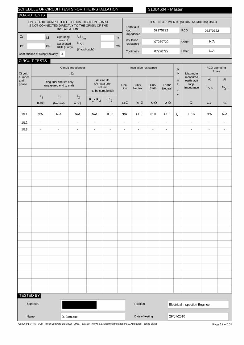
1/L1
1/L2
1/L3
2/L1
2/L2
2/L3
3/TP
4/TP
Sub Mains(DB 2,DB 2A)
Sub Mains(DB 3,DB 3A)
Sub Mains(DB 1,DB 1A)
Aircon
SPARE
Sub Mains(DB 4,DB 4A)
Heating 2
Sub Mains(DB Woodwork Power)
H
H
H
G
-
H
H
H
C
C
C
C
-
C
C
C
2
2
2
2
-
1
1
1
10
10
10
6
-
10
10
6
10
10
10
6
-
Micc
Micc
6
5
5
5
0.4
-
5
5
5
88 Fuse HRC
88 Fuse HRC
88 Fuse HRC
88 Fuse HRC
-
88 Fuse HRC
88 Fuse HRC
88 Fuse HRC
gG
gG
gG
gG
-
gG
gG
gG
63
63
63
32
-
63
63
40
80
80
80
80
-
80
80
80
N/A
N/A
N/A
N/A
-
N/A
N/A
N/A
0.82
0.82
0.82
1.04
-
0.82
0.82
1.35
Copyright © AMTECH Power Software Ltd 1992 - 2008, FastTest Pro v9.2.1, Electrical Instullations & Appliance Testing uk ltd
TO BE COMPLETED IN EVERY CASE ONLY TO BE COMPLETED IF THE DISTRIBUTION BOARD IS NOT CONNECTED DIRECTLY TO THE ORIGIN OF THE INSTALLATION
Location of distribution board
Distribution board designation
Supply to distributionboard is from
Overcurrent protective device for the distribution circuitTypeBS(EN) Rating A
No of phases Nominal Voltage V
Associated RCD (if any)
BS(EN)
RCD No of poles
RCD rating,I
mA∆ n
Circuitnumberandphase
Circuitdesignation
Typeof
wiring
Refe-rence method
Noof
pointsserved
Circuitconductors
csa
Live cpc
mm mm2 2
Max.per-
mitteddisc-
onnec-tiontime
s
Overcurrent protective device
BS(EN) Type No
Rating Shortcircuitcapa-city
RCD
Op.curr-ent
I∆n
Max.per-mitt-edZs
Ω
PVC/PVCcables
PVC cables in metallic conduit
PVC cables in non-metallic
conduit
PVC cables in metallic trunking
PVC cables in non-metallic
trunking
PVC/SWAcables
XLPE/SWAcables
Mineralinsulatedcables
Other
31004604 - Master
A B C D E F G H O
Page 13 of 107
SCHEDULE OF CIRCUIT DETAILS FOR THE INSTALLATION
CIRCUIT DETAILS
BOARD DETAILS
WIRING CODE
kAA
0.13
3.66
N/A
N/A
07270722
07270722
07270722
07270722
N/A
1/L1
1/L2
1/L3
2/L1
2/L2
2/L3
3/TP
4/TP
N/A
N/A
N/A
N/A
-
N/A
N/A
N/A
N/A
N/A
N/A
N/A
-
N/A
N/A
N/A
N/A
N/A
N/A
N/A
-
N/A
N/A
N/A
0.04
0.03
0.04
LIM
-
0.03
N/A
0.10
N/A
N/A
N/A
LIM
-
N/A
0.10
N/A
N/A
N/A
N/A
N/A
-
N/A
>10
>10
>10
>10
>10
LIM
-
>10
>10
>10
>10
>10
>10
LIM
-
>10
>10
>10
>10
>10
>10
LIM
-
>10
>10
>10
ü
ü
ü
ü
ü
ü
0.16
0.16
0.17
LIM
-
0.16
0.21
0.22
N/A N/A
N/A N/A
N/A N/A
N/A N/A
- -
N/A N/A
N/A N/A
N/A N/A
Electrical Inspection Engineer
D. Jameson
Copyright © AMTECH Power Software Ltd 1992 - 2008, FastTest Pro v9.2.1, Electrical Instullations & Appliance Testing uk ltd
ONLY TO BE COMPLETED IF THE DISTRIBUTION BOARDIS NOT CONNECTED DIRECTLY TO THE ORIGIN OF THE
INSTALLATION
Zs
Ipf kA
Ω Operating times ofassociatedRCD (if any)
5I
(if applicable)
At I ∆ n ms
ms
N/A
TEST INSTRUMENTS (SERIAL NUMBERS) USED
Earth faultloopimpedance
Insulation resistance
Continuity
RCD
Other
Other
Circuitnumberandphase
Circuit impedances
Ω
Ring final circuits only(measured end to end)
r
(Line)
r
(Neutral)
r
(cpc)
1 2n
All circuits(At least one
columnto be completed)
R + R1 2 R 2
Insulation resistance
Line/Line
Line/Neutral
Line/Earth
Earth/Neutral
Polarity
Ω Ω Ω ΩMMMM
RCD operating times
Maximummeasuredearth fault
loop impedance
Ω msms
At
I ∆ n
Signature
Name
Position
Date of testing
31004604 - Master
Page 14 of 107
n∆
At
5I∆ n
29/07/2010
SCHEDULE OF CIRCUIT TESTS FOR THE INSTALLATION
CIRCUIT TESTS
TESTED BY
BOARD TESTS
Confirmation of Supply polarity ü

Ground floor corridor
DB 2
Sub Mains(L+P DB, 1/L1)
88 Fuse HRC gG 63
1 230
N/A
N/A
N/A
1/L1
2/L1
3/L1
4/L1
5/L1
6/L1
7/L1
8/L1
9/L1
10/L1
11/L1
12/L1
13/L1
14/L1
15/L1
16/L1
Hall lights
Entrance hall lights
Head of year & MI lights
Office & deputy head lts
Female WC & entrance lts
Corridor lights
Staff room lights
Staff room lights
Store rooms lights
Class 4 lights
Class 3 lights
MI room fire
SPARE
SPARE
SPARE
SPARE
D
D
D
D
D
D
D
D
D
D
D
D
-
-
-
-
B
B
B
B
B
B
B
B
B
B
B
B
-
-
-
-
2
2
N/V
7
14
4
8
4
N/V
9
9
1
-
-
-
-
1.5
1.5
1.5
1.5
1.5
1.5
1.5
1.5
1.5
1.5
1.5
2.5
-
-
-
-
TRUNK
TRUNK
TRUNK
TRUNK
TRUNK
TRUNK
TRUNK
TRUNK
TRUNK
TRUNK
TRUNK
TRUNK
-
-
-
-
0.4
0.4
0.4
0.4
0.4
0.4
0.4
0.4
0.4
0.4
0.4
0.4
-
-
-
-
3871 MCB
3871 MCB
3871 MCB
3871 MCB
3871 MCB
3871 MCB
3871 MCB
3871 MCB
3871 MCB
3871 MCB
3871 MCB
3871 MCB
-
-
-
-
2
2
2
2
2
2
2
2
2
2
2
2
-
-
-
-
10
10
10
10
10
10
10
10
10
10
10
16
-
-
-
-
9
9
9
9
9
9
9
9
9
9
9
9
-
-
-
-
N/A
N/A
N/A
N/A
N/A
N/A
N/A
N/A
N/A
N/A
N/A
N/A
-
-
-
-
3.29
3.29
3.29
3.29
3.29
3.29
3.29
3.29
3.29
3.29
3.29
2.05
-
-
-
-
Copyright © AMTECH Power Software Ltd 1992 - 2008, FastTest Pro v9.2.1, Electrical Instullations & Appliance Testing uk ltd
TO BE COMPLETED IN EVERY CASE ONLY TO BE COMPLETED IF THE DISTRIBUTION BOARD IS NOT CONNECTED DIRECTLY TO THE ORIGIN OF THE INSTALLATION
Location of distribution board
Distribution board designation
Supply to distributionboard is from
Overcurrent protective device for the distribution circuitTypeBS(EN) Rating A
No of phases Nominal Voltage V
Associated RCD (if any)
BS(EN)
RCD No of poles
RCD rating,I
mA∆ n
Circuitnumberandphase
Circuitdesignation
Typeof
wiring
Refe-rence method
Noof
pointsserved
Circuitconductors
csa
Live cpc
mm mm2 2
Max.per-
mitteddisc-
onnec-tiontime
s
Overcurrent protective device
BS(EN) Type No
Rating Shortcircuitcapa-city
RCD
Op.curr-ent
I∆n
Max.per-mitt-edZs
Ω
PVC/PVCcables
PVC cables in metallic conduit
PVC cables in non-metallic
conduit
PVC cables in metallic trunking
PVC cables in non-metallic
trunking
PVC/SWAcables
XLPE/SWAcables
Mineralinsulatedcables
Other
31004604 - Master
A B C D E F G H O
Page 15 of 107
SCHEDULE OF CIRCUIT DETAILS FOR THE INSTALLATION
CIRCUIT DETAILS
BOARD DETAILS
WIRING CODE
kAA

0.18
1.41
N/A
N/A
07270722
07270722
07270722
07270722
N/A
1/L1
2/L1
3/L1
4/L1
5/L1
6/L1
7/L1
8/L1
9/L1
10/L1
11/L1
12/L1
13/L1
14/L1
15/L1
16/L1
N/A
N/A
UNABLE
N/A
N/A
N/A
N/A
N/A
UNABLE
N/A
N/A
N/A
-
-
-
-
N/A
N/A
TO
N/A
N/A
N/A
N/A
N/A
TO
N/A
N/A
N/A
-
-
-
-
N/A
N/A
LOCATE
N/A
N/A
N/A
N/A
N/A
LOCATE
N/A
N/A
N/A
-
-
-
-
0.20
0.22
LIM
N/A
N/A
N/A
N/A
N/A
LIM
N/A
N/A
0.16
-
-
-
-
N/A
N/A
LIM
0.08
0.12
0.11
0.15
0.16
LIM
0.14
0.14
N/A
-
-
-
-
N/A
N/A
N/A
N/A
N/A
N/A
N/A
N/A
N/A
N/A
N/A
N/A
-
-
-
-
LIM
LIM
LIM
LIM
LIM
LIM
LIM
LIM
LIM
LIM
LIM
>10
-
-
-
-
35.1
35.2
LIM
35.2
35.2
25.7
>10
>10
LIM
>10
>10
>10
-
-
-
-
35.0
LIM
35.1
31.4
34.4
24.9
>10
>10
LIM
>10
>10
>10
-
-
-
-
ü
ü
ü
ü
ü
ü
ü
ü
ü
ü
0.38
0.44
LIM
0.34
0.34
0.33
0.36
0.40
LIM
0.36
0.39
0.34
-
-
-
-
N/A N/A
N/A N/A
N/A N/A
N/A N/A
N/A N/A
N/A N/A
N/A N/A
N/A N/A
N/A N/A
N/A N/A
N/A N/A
N/A N/A
- -
- -
- -
- -
Electrical Inspection Engineer
D. Jameson
Copyright © AMTECH Power Software Ltd 1992 - 2008, FastTest Pro v9.2.1, Electrical Instullations & Appliance Testing uk ltd
ONLY TO BE COMPLETED IF THE DISTRIBUTION BOARDIS NOT CONNECTED DIRECTLY TO THE ORIGIN OF THE
INSTALLATION
Zs
Ipf kA
Ω Operating times ofassociatedRCD (if any)
5I
(if applicable)
At I ∆ n ms
ms
N/A
TEST INSTRUMENTS (SERIAL NUMBERS) USED
Earth faultloopimpedance
Insulation resistance
Continuity
RCD
Other
Other
Circuitnumberandphase
Circuit impedances
Ω
Ring final circuits only(measured end to end)
r
(Line)
r
(Neutral)
r
(cpc)
1 2n
All circuits(At least one
columnto be completed)
R + R1 2 R 2
Insulation resistance
Line/Line
Line/Neutral
Line/Earth
Earth/Neutral
Polarity
Ω Ω Ω ΩMMMM
RCD operating times
Maximummeasuredearth fault
loop impedance
Ω msms
At
I ∆ n
Signature
Name
Position
Date of testing
31004604 - Master
Page 16 of 107
n∆
At
5I∆ n
29/07/2010
SCHEDULE OF CIRCUIT TESTS FOR THE INSTALLATION
CIRCUIT TESTS
TESTED BY
BOARD TESTS
Confirmation of Supply polarity ü
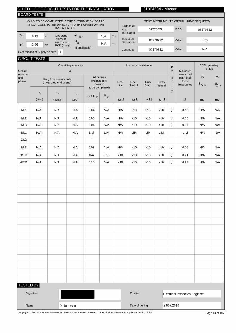
Ground floor corridor
DB 2A
Sub Mains(L+P DB, 1/L1)
88 Fuse HRC gG 63
1 230
N/A
N/A
N/A
1/L1
2/L1
3/L1
4/L1
5/L1
6/L1
7/L1
Entrance, main off skts
C'takers & staff rm skts
Class 3 & 4 sockets
SPARE
SPARE
SPARE
SPARE
D
D
D
-
-
-
-
B
B
B
-
-
-
-
N/V
16
11
-
-
-
-
2.5
2.5
2.5
-
-
-
-
TRUNK
TRUNK
TRUNK
-
-
-
-
0.4
0.4
0.4
-
-
-
-
61009
61009
61009
-
-
-
-
C
C
C
-
-
-
-
32
32
32
-
-
-
-
10
10
10
-
-
-
-
30
30
30
-
-
-
-
0.72
0.72
0.72
-
-
-
-
Copyright © AMTECH Power Software Ltd 1992 - 2008, FastTest Pro v9.2.1, Electrical Instullations & Appliance Testing uk ltd
TO BE COMPLETED IN EVERY CASE ONLY TO BE COMPLETED IF THE DISTRIBUTION BOARD IS NOT CONNECTED DIRECTLY TO THE ORIGIN OF THE INSTALLATION
Location of distribution board
Distribution board designation
Supply to distributionboard is from
Overcurrent protective device for the distribution circuitTypeBS(EN) Rating A
No of phases Nominal Voltage V
Associated RCD (if any)
BS(EN)
RCD No of poles
RCD rating,I
mA∆ n
Circuitnumberandphase
Circuitdesignation
Typeof
wiring
Refe-rence method
Noof
pointsserved
Circuitconductors
csa
Live cpc
mm mm2 2
Max.per-
mitteddisc-
onnec-tiontime
s
Overcurrent protective device
BS(EN) Type No
Rating Shortcircuitcapa-city
RCD
Op.curr-ent
I∆n
Max.per-mitt-edZs
Ω
PVC/PVCcables
PVC cables in metallic conduit
PVC cables in non-metallic
conduit
PVC cables in metallic trunking
PVC cables in non-metallic
trunking
PVC/SWAcables
XLPE/SWAcables
Mineralinsulatedcables
Other
31004604 - Master
A B C D E F G H O
Page 17 of 107
SCHEDULE OF CIRCUIT DETAILS FOR THE INSTALLATION
CIRCUIT DETAILS
BOARD DETAILS
WIRING CODE
kAA
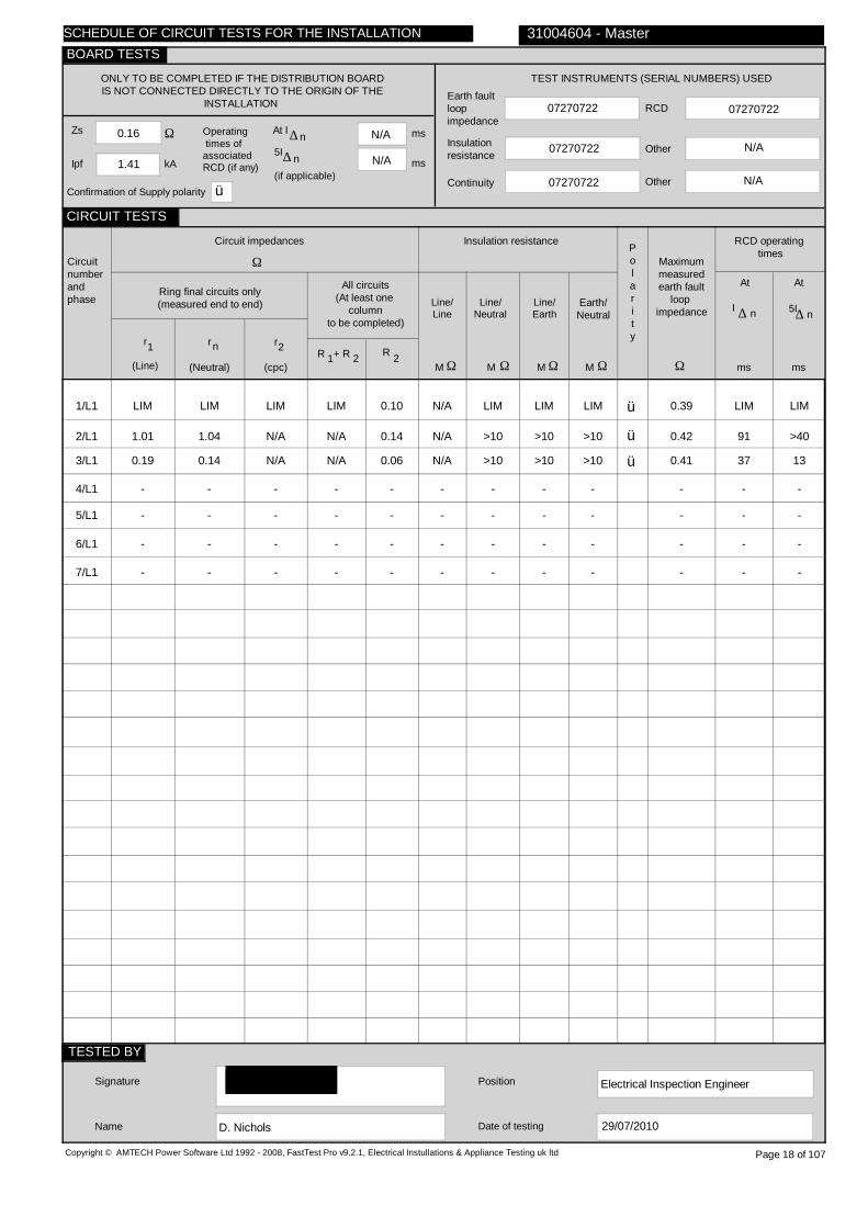
0.16
1.41
N/A
N/A
07270722
07270722
07270722
07270722
N/A
1/L1
2/L1
3/L1
4/L1
5/L1
6/L1
7/L1
LIM
1.01
0.19
-
-
-
-
LIM
1.04
0.14
-
-
-
-
LIM
N/A
N/A
-
-
-
-
LIM
N/A
N/A
-
-
-
-
0.10
0.14
0.06
-
-
-
-
N/A
N/A
N/A
-
-
-
-
LIM
>10
>10
-
-
-
-
LIM
>10
>10
-
-
-
-
LIM
>10
>10
-
-
-
-
ü
ü
ü
0.39
0.42
0.41
-
-
-
-
LIM LIM
91 >40
37 13
- -
- -
- -
- -
Electrical Inspection Engineer
D. Nichols
Copyright © AMTECH Power Software Ltd 1992 - 2008, FastTest Pro v9.2.1, Electrical Instullations & Appliance Testing uk ltd
ONLY TO BE COMPLETED IF THE DISTRIBUTION BOARDIS NOT CONNECTED DIRECTLY TO THE ORIGIN OF THE
INSTALLATION
Zs
Ipf kA
Ω Operating times ofassociatedRCD (if any)
5I
(if applicable)
At I ∆ n ms
ms
N/A
TEST INSTRUMENTS (SERIAL NUMBERS) USED
Earth faultloopimpedance
Insulation resistance
Continuity
RCD
Other
Other
Circuitnumberandphase
Circuit impedances
Ω
Ring final circuits only(measured end to end)
r
(Line)
r
(Neutral)
r
(cpc)
1 2n
All circuits(At least one
columnto be completed)
R + R1 2 R 2
Insulation resistance
Line/Line
Line/Neutral
Line/Earth
Earth/Neutral
Polarity
Ω Ω Ω ΩMMMM
RCD operating times
Maximummeasuredearth fault
loop impedance
Ω msms
At
I ∆ n
Signature
Name
Position
Date of testing
31004604 - Master
Page 18 of 107
n∆
At
5I∆ n
29/07/2010
SCHEDULE OF CIRCUIT TESTS FOR THE INSTALLATION
CIRCUIT TESTS
TESTED BY
BOARD TESTS
Confirmation of Supply polarity ü

First floor corridor
DB 3
Sub Mains(L+P DB, 1/L2)
88 Fuse HRC gG 63
1 230
N/A
N/A
N/A
1/L2
2/L2
3/L2
4/L2
5/L2
6/L2
7/L2
8/L2
9/L2
10/L2
11/L2
12/L2
13/L2
14/L2
15/L2
Room 7 lights
Room 6 lights & store
Corridor lights
Extended serv & music rms
IT room row 3 lights
IT room row 2 lights
IT room row 1 lights
Lab S1 row 3 lights
Lab S1 row 2 lights
Lab S1 row 1 lights
Sub Mains(FDB Room 6)
Sub Mains(FDB Room 7)
Sub Mains(FDB S1)
Sub Mains(DB 3B)
Unable to locate
D
D
D
D
D
D
D
D
D
D
H
H
H
D
H
B
B
B
B
B
B
B
B
B
B
C
C
C
B
C
6
6
4
4
4
4
4
4
4
4
1
1
1
1
N/V
1.5
1.5
1.5
1.5
1.5
1.5
1.5
1.5
1.5
1.5
6
6
6
10
1.5
TRUNK
TRUNK
TRUNK
TRUNK
TRUNK
TRUNK
TRUNK
TRUNK
TRUNK
6
TRUNK
6
6
10
Micc
0.4
0.4
0.4
0.4
0.4
0.4
0.4
0.4
0.4
0.4
5
5
5
5
0.4
3871 MCB
3871 MCB
3871 MCB
3871 MCB
3871 MCB
3871 MCB
3871 MCB
3871 MCB
3871 MCB
3871 MCB
3871 MCB
3871 MCB
3871 MCB
3871 MCB
3871 MCB
2
2
2
2
2
2
2
2
2
2
3
2
2
3
2
10
10
10
10
10
10
10
10
10
10
32
32
32
50
16
9
9
9
9
9
9
9
9
9
9
9
9
9
9
9
N/A
N/A
N/A
N/A
N/A
N/A
N/A
N/A
N/A
N/A
N/A
N/A
N/A
N/A
N/A
3.29
3.29
3.29
3.29
3.29
3.29
3.29
3.29
3.29
3.29
0.72
1.44
1.44
0.46
2.05
Copyright © AMTECH Power Software Ltd 1992 - 2008, FastTest Pro v9.2.1, Electrical Instullations & Appliance Testing uk ltd
TO BE COMPLETED IN EVERY CASE ONLY TO BE COMPLETED IF THE DISTRIBUTION BOARD IS NOT CONNECTED DIRECTLY TO THE ORIGIN OF THE INSTALLATION
Location of distribution board
Distribution board designation
Supply to distributionboard is from
Overcurrent protective device for the distribution circuitTypeBS(EN) Rating A
No of phases Nominal Voltage V
Associated RCD (if any)
BS(EN)
RCD No of poles
RCD rating,I
mA∆ n
Circuitnumberandphase
Circuitdesignation
Typeof
wiring
Refe-rence method
Noof
pointsserved
Circuitconductors
csa
Live cpc
mm mm2 2
Max.per-
mitteddisc-
onnec-tiontime
s
Overcurrent protective device
BS(EN) Type No
Rating Shortcircuitcapa-city
RCD
Op.curr-ent
I∆n
Max.per-mitt-edZs
Ω
PVC/PVCcables
PVC cables in metallic conduit
PVC cables in non-metallic
conduit
PVC cables in metallic trunking
PVC cables in non-metallic
trunking
PVC/SWAcables
XLPE/SWAcables
Mineralinsulatedcables
Other
31004604 - Master
A B C D E F G H O
Page 19 of 107
SCHEDULE OF CIRCUIT DETAILS FOR THE INSTALLATION
CIRCUIT DETAILS
BOARD DETAILS
WIRING CODE
kAA

0.16
1.47
N/A
N/A
0707070985
0707070985
0707070985
0707070985
N/A
1/L2
2/L2
3/L2
4/L2
5/L2
6/L2
7/L2
8/L2
9/L2
10/L2
11/L2
12/L2
13/L2
14/L2
15/L2
N/A
N/A
N/A
N/A
N/A
N/A
N/A
N/A
N/A
N/A
N/A
N/A
N/A
N/A
UNABLE
N/A
N/A
N/A
N/A
N/A
N/A
N/A
N/A
N/A
N/A
N/A
N/A
N/A
N/A
TO
N/A
N/A
N/A
N/A
N/A
N/A
N/A
N/A
N/A
N/A
N/A
N/A
N/A
N/A
LOCATE
N/A
N/A
N/A
N/A
N/A
N/A
N/A
N/A
N/A
N/A
0.06
0.08
0.02
0.02
LIM
0.08
0.15
0.04
0.12
0.12
0.12
0.11
0.24
0.24
0.25
N/A
N/A
N/A
N/A
LIM
N/A
N/A
N/A
N/A
N/A
N/A
N/A
N/A
N/A
N/A
N/A
N/A
N/A
N/A
N/A
LIM
LIM
LIM
LIM
LIM
LIM
LIM
LIM
LIM
LIM
>10
>10
>10
>10
LIM
>10
>10
>10
>10
>10
>10
>10
>10
>10
>10
>10
>10
>10
>10
LIM
>10
>10
>10
>10
>10
>10
>10
>10
>10
>10
>10
>10
>10
>10
LIM
ü
ü
ü
ü
ü
ü
ü
ü
ü
ü
ü
ü
ü
ü
0.30
0.36
0.24
0.28
0.34
0.34
0.36
0.44
0.45
0.46
0.22
0.23
0.15
0.18
LIM
N/A N/A
N/A N/A
N/A N/A
N/A N/A
N/A N/A
N/A N/A
N/A N/A
N/A N/A
N/A N/A
N/A N/A
N/A N/A
N/A N/A
N/A N/A
N/A N/A
N/A N/A
Electrical Inspection Engineer
D. Nichols
Copyright © AMTECH Power Software Ltd 1992 - 2008, FastTest Pro v9.2.1, Electrical Instullations & Appliance Testing uk ltd
ONLY TO BE COMPLETED IF THE DISTRIBUTION BOARDIS NOT CONNECTED DIRECTLY TO THE ORIGIN OF THE
INSTALLATION
Zs
Ipf kA
Ω Operating times ofassociatedRCD (if any)
5I
(if applicable)
At I ∆ n ms
ms
N/A
TEST INSTRUMENTS (SERIAL NUMBERS) USED
Earth faultloopimpedance
Insulation resistance
Continuity
RCD
Other
Other
Circuitnumberandphase
Circuit impedances
Ω
Ring final circuits only(measured end to end)
r
(Line)
r
(Neutral)
r
(cpc)
1 2n
All circuits(At least one
columnto be completed)
R + R1 2 R 2
Insulation resistance
Line/Line
Line/Neutral
Line/Earth
Earth/Neutral
Polarity
Ω Ω Ω ΩMMMM
RCD operating times
Maximummeasuredearth fault
loop impedance
Ω msms
At
I ∆ n
Signature
Name
Position
Date of testing
31004604 - Master
Page 20 of 107
n∆
At
5I∆ n
29/07/2010
SCHEDULE OF CIRCUIT TESTS FOR THE INSTALLATION
CIRCUIT TESTS
TESTED BY
BOARD TESTS
Confirmation of Supply polarity ü

Room 6
FDB Room 6
Sub Mains(DB 3, 11/L2)
3871 MCB 3 32
1 230
4293 RCD
2
30
1/L2
Room 6 sockets
B
B
7
2.5
2.5
0.4
4293
LIM
30
2.5
30
N/V
Copyright © AMTECH Power Software Ltd 1992 - 2008, FastTest Pro v9.2.1, Electrical Instullations & Appliance Testing uk ltd
TO BE COMPLETED IN EVERY CASE ONLY TO BE COMPLETED IF THE DISTRIBUTION BOARD IS NOT CONNECTED DIRECTLY TO THE ORIGIN OF THE INSTALLATION
Location of distribution board
Distribution board designation
Supply to distributionboard is from
Overcurrent protective device for the distribution circuitTypeBS(EN) Rating A
No of phases Nominal Voltage V
Associated RCD (if any)
BS(EN)
RCD No of poles
RCD rating,I
mA∆ n
Circuitnumberandphase
Circuitdesignation
Typeof
wiring
Refe-rence method
Noof
pointsserved
Circuitconductors
csa
Live cpc
mm mm2 2
Max.per-
mitteddisc-
onnec-tiontime
s
Overcurrent protective device
BS(EN) Type No
Rating Shortcircuitcapa-city
RCD
Op.curr-ent
I∆n
Max.per-mitt-edZs
Ω
PVC/PVCcables
PVC cables in metallic conduit
PVC cables in non-metallic
conduit
PVC cables in metallic trunking
PVC cables in non-metallic
trunking
PVC/SWAcables
XLPE/SWAcables
Mineralinsulatedcables
Other
31004604 - Master
A B C D E F G H O
Page 21 of 107
SCHEDULE OF CIRCUIT DETAILS FOR THE INSTALLATION
CIRCUIT DETAILS
BOARD DETAILS
WIRING CODE
kAA

0.22
0.98
27
7
0707070985
0707070985
0707070985
0707070985
N/A
1/L2
0.22
0.23
0.03
0.02
0.03
N/A
>10
>10
>10
ü
0.43
27 7
Electrical Inspection Engineer
D. Nichols
Copyright © AMTECH Power Software Ltd 1992 - 2008, FastTest Pro v9.2.1, Electrical Instullations & Appliance Testing uk ltd
ONLY TO BE COMPLETED IF THE DISTRIBUTION BOARDIS NOT CONNECTED DIRECTLY TO THE ORIGIN OF THE
INSTALLATION
Zs
Ipf kA
Ω Operating times ofassociatedRCD (if any)
5I
(if applicable)
At I ∆ n ms
ms
N/A
TEST INSTRUMENTS (SERIAL NUMBERS) USED
Earth faultloopimpedance
Insulation resistance
Continuity
RCD
Other
Other
Circuitnumberandphase
Circuit impedances
Ω
Ring final circuits only(measured end to end)
r
(Line)
r
(Neutral)
r
(cpc)
1 2n
All circuits(At least one
columnto be completed)
R + R1 2 R 2
Insulation resistance
Line/Line
Line/Neutral
Line/Earth
Earth/Neutral
Polarity
Ω Ω Ω ΩMMMM
RCD operating times
Maximummeasuredearth fault
loop impedance
Ω msms
At
I ∆ n
Signature
Name
Position
Date of testing
31004604 - Master
Page 22 of 107
n∆
At
5I∆ n
29/07/2010
SCHEDULE OF CIRCUIT TESTS FOR THE INSTALLATION
CIRCUIT TESTS
TESTED BY
BOARD TESTS
Confirmation of Supply polarity ü

Room 7
FDB Room 7
Sub Mains(DB 3, 12/L2)
3871 MCB 2 32
1 230
4293 RCD
2
30
1/L2
Room 7 sockets
B
B
7
2.5
COND
5
4293
2
63
6
30
0.52
Copyright © AMTECH Power Software Ltd 1992 - 2008, FastTest Pro v9.2.1, Electrical Instullations & Appliance Testing uk ltd
TO BE COMPLETED IN EVERY CASE ONLY TO BE COMPLETED IF THE DISTRIBUTION BOARD IS NOT CONNECTED DIRECTLY TO THE ORIGIN OF THE INSTALLATION
Location of distribution board
Distribution board designation
Supply to distributionboard is from
Overcurrent protective device for the distribution circuitTypeBS(EN) Rating A
No of phases Nominal Voltage V
Associated RCD (if any)
BS(EN)
RCD No of poles
RCD rating,I
mA∆ n
Circuitnumberandphase
Circuitdesignation
Typeof
wiring
Refe-rence method
Noof
pointsserved
Circuitconductors
csa
Live cpc
mm mm2 2
Max.per-
mitteddisc-
onnec-tiontime
s
Overcurrent protective device
BS(EN) Type No
Rating Shortcircuitcapa-city
RCD
Op.curr-ent
I∆n
Max.per-mitt-edZs
Ω
PVC/PVCcables
PVC cables in metallic conduit
PVC cables in non-metallic
conduit
PVC cables in metallic trunking
PVC cables in non-metallic
trunking
PVC/SWAcables
XLPE/SWAcables
Mineralinsulatedcables
Other
31004604 - Master
A B C D E F G H O
Page 23 of 107
SCHEDULE OF CIRCUIT DETAILS FOR THE INSTALLATION
CIRCUIT DETAILS
BOARD DETAILS
WIRING CODE
kAA

0.23
0.98
36
11
0707070985
0707070985
0707070985
0707070985
N/A
1/L2
0.32
0.31
0.05
N/A
0.05
N/A
>10
>10
>10
ü
0.41
36 11
Electrical Inspection Engineer
D. Nichols
Copyright © AMTECH Power Software Ltd 1992 - 2008, FastTest Pro v9.2.1, Electrical Instullations & Appliance Testing uk ltd
ONLY TO BE COMPLETED IF THE DISTRIBUTION BOARDIS NOT CONNECTED DIRECTLY TO THE ORIGIN OF THE
INSTALLATION
Zs
Ipf kA
Ω Operating times ofassociatedRCD (if any)
5I
(if applicable)
At I ∆ n ms
ms
N/A
TEST INSTRUMENTS (SERIAL NUMBERS) USED
Earth faultloopimpedance
Insulation resistance
Continuity
RCD
Other
Other
Circuitnumberandphase
Circuit impedances
Ω
Ring final circuits only(measured end to end)
r
(Line)
r
(Neutral)
r
(cpc)
1 2n
All circuits(At least one
columnto be completed)
R + R1 2 R 2
Insulation resistance
Line/Line
Line/Neutral
Line/Earth
Earth/Neutral
Polarity
Ω Ω Ω ΩMMMM
RCD operating times
Maximummeasuredearth fault
loop impedance
Ω msms
At
I ∆ n
Signature
Name
Position
Date of testing
31004604 - Master
Page 24 of 107
n∆
At
5I∆ n
29/07/2010
SCHEDULE OF CIRCUIT TESTS FOR THE INSTALLATION
CIRCUIT TESTS
TESTED BY
BOARD TESTS
Confirmation of Supply polarity ü

Room S1 lab
FDB S1
Sub Mains(DB 3, 13/L2)
3871 MCB 2 32
1 230
4293 RCD
2
30
1/L2
S1 lab sockets
H
C
14
1.5
1.5
0.4
4293
2
30
5
30
0.82
Copyright © AMTECH Power Software Ltd 1992 - 2008, FastTest Pro v9.2.1, Electrical Instullations & Appliance Testing uk ltd
TO BE COMPLETED IN EVERY CASE ONLY TO BE COMPLETED IF THE DISTRIBUTION BOARD IS NOT CONNECTED DIRECTLY TO THE ORIGIN OF THE INSTALLATION
Location of distribution board
Distribution board designation
Supply to distributionboard is from
Overcurrent protective device for the distribution circuitTypeBS(EN) Rating A
No of phases Nominal Voltage V
Associated RCD (if any)
BS(EN)
RCD No of poles
RCD rating,I
mA∆ n
Circuitnumberandphase
Circuitdesignation
Typeof
wiring
Refe-rence method
Noof
pointsserved
Circuitconductors
csa
Live cpc
mm mm2 2
Max.per-
mitteddisc-
onnec-tiontime
s
Overcurrent protective device
BS(EN) Type No
Rating Shortcircuitcapa-city
RCD
Op.curr-ent
I∆n
Max.per-mitt-edZs
Ω
PVC/PVCcables
PVC cables in metallic conduit
PVC cables in non-metallic
conduit
PVC cables in metallic trunking
PVC cables in non-metallic
trunking
PVC/SWAcables
XLPE/SWAcables
Mineralinsulatedcables
Other
31004604 - Master
A B C D E F G H O
Page 25 of 107
SCHEDULE OF CIRCUIT DETAILS FOR THE INSTALLATION
CIRCUIT DETAILS
BOARD DETAILS
WIRING CODE
kAA

0.15
1.16
28
7
07270722
07270722
07270722
07270722
N/A
1/L2
0.16
0.15
0.17
0.10
N/A
N/A
>10
>10
>10
ü
0.67
28 7
Electrical Inspection Engineer
D. Nichols
Copyright © AMTECH Power Software Ltd 1992 - 2008, FastTest Pro v9.2.1, Electrical Instullations & Appliance Testing uk ltd
ONLY TO BE COMPLETED IF THE DISTRIBUTION BOARDIS NOT CONNECTED DIRECTLY TO THE ORIGIN OF THE
INSTALLATION
Zs
Ipf kA
Ω Operating times ofassociatedRCD (if any)
5I
(if applicable)
At I ∆ n ms
ms
N/A
TEST INSTRUMENTS (SERIAL NUMBERS) USED
Earth faultloopimpedance
Insulation resistance
Continuity
RCD
Other
Other
Circuitnumberandphase
Circuit impedances
Ω
Ring final circuits only(measured end to end)
r
(Line)
r
(Neutral)
r
(cpc)
1 2n
All circuits(At least one
columnto be completed)
R + R1 2 R 2
Insulation resistance
Line/Line
Line/Neutral
Line/Earth
Earth/Neutral
Polarity
Ω Ω Ω ΩMMMM
RCD operating times
Maximummeasuredearth fault
loop impedance
Ω msms
At
I ∆ n
Signature
Name
Position
Date of testing
31004604 - Master
Page 26 of 107
n∆
At
5I∆ n
29/07/2010
SCHEDULE OF CIRCUIT TESTS FOR THE INSTALLATION
CIRCUIT TESTS
TESTED BY
BOARD TESTS
Confirmation of Supply polarity ü

IT room
DB 3B
Sub Mains(DB 3, 14/L2)
3871 MCB 3 50
1 230
N/A
N/A
N/A
1/L2
2/L2
3/L2
4/L2
5/L2
6/L2
Network hub & projec skts
Near wall dado sockets
Far wall dado sockets
Central island sockets
SPARE
SPARE
E
E
E
E
-
-
B
B
B
B
-
-
7
10
8
12
-
-
2.5
2.5
2.5
2.5
-
-
1.5
1.5
1.5
1.5
-
-
0.4
0.4
0.4
0.4
-
-
61009
61009
61009
61009
-
-
B
B
B
B
-
-
32
32
32
32
-
-
6
6
6
6
-
-
30
30
30
30
-
-
1.44
1.44
1.44
1.44
-
-
Copyright © AMTECH Power Software Ltd 1992 - 2008, FastTest Pro v9.2.1, Electrical Instullations & Appliance Testing uk ltd
TO BE COMPLETED IN EVERY CASE ONLY TO BE COMPLETED IF THE DISTRIBUTION BOARD IS NOT CONNECTED DIRECTLY TO THE ORIGIN OF THE INSTALLATION
Location of distribution board
Distribution board designation
Supply to distributionboard is from
Overcurrent protective device for the distribution circuitTypeBS(EN) Rating A
No of phases Nominal Voltage V
Associated RCD (if any)
BS(EN)
RCD No of poles
RCD rating,I
mA∆ n
Circuitnumberandphase
Circuitdesignation
Typeof
wiring
Refe-rence method
Noof
pointsserved
Circuitconductors
csa
Live cpc
mm mm2 2
Max.per-
mitteddisc-
onnec-tiontime
s
Overcurrent protective device
BS(EN) Type No
Rating Shortcircuitcapa-city
RCD
Op.curr-ent
I∆n
Max.per-mitt-edZs
Ω
PVC/PVCcables
PVC cables in metallic conduit
PVC cables in non-metallic
conduit
PVC cables in metallic trunking
PVC cables in non-metallic
trunking
PVC/SWAcables
XLPE/SWAcables
Mineralinsulatedcables
Other
31004604 - Master
A B C D E F G H O
Page 27 of 107
SCHEDULE OF CIRCUIT DETAILS FOR THE INSTALLATION
CIRCUIT DETAILS
BOARD DETAILS
WIRING CODE
kAA

0.18
1.42
N/A
N/A
0707070985
0707070985
0707070985
0707070985
N/A
1/L2
2/L2
3/L2
4/L2
5/L2
6/L2
0.24
0.27
0.34
0.31
-
-
0.23
0.28
0.33
0.32
-
-
0.11
0.44
0.78
0.40
-
-
0.06
0.20
0.30
0.18
-
-
N/A
N/A
N/A
N/A
-
-
N/A
N/A
N/A
N/A
-
-
>10
>10
>10
>10
-
-
>10
>10
>10
>10
-
-
>10
>10
>10
>10
-
-
ü
ü
ü
ü
0.43
0.47
0.62
0.48
-
-
30 10
43 16
42 24
20 10
- -
- -
Electrical Inspection Engineer
D. Nichols
Copyright © AMTECH Power Software Ltd 1992 - 2008, FastTest Pro v9.2.1, Electrical Instullations & Appliance Testing uk ltd
ONLY TO BE COMPLETED IF THE DISTRIBUTION BOARDIS NOT CONNECTED DIRECTLY TO THE ORIGIN OF THE
INSTALLATION
Zs
Ipf kA
Ω Operating times ofassociatedRCD (if any)
5I
(if applicable)
At I ∆ n ms
ms
N/A
TEST INSTRUMENTS (SERIAL NUMBERS) USED
Earth faultloopimpedance
Insulation resistance
Continuity
RCD
Other
Other
Circuitnumberandphase
Circuit impedances
Ω
Ring final circuits only(measured end to end)
r
(Line)
r
(Neutral)
r
(cpc)
1 2n
All circuits(At least one
columnto be completed)
R + R1 2 R 2
Insulation resistance
Line/Line
Line/Neutral
Line/Earth
Earth/Neutral
Polarity
Ω Ω Ω ΩMMMM
RCD operating times
Maximummeasuredearth fault
loop impedance
Ω msms
At
I ∆ n
Signature
Name
Position
Date of testing
31004604 - Master
Page 28 of 107
n∆
At
5I∆ n
29/07/2010
SCHEDULE OF CIRCUIT TESTS FOR THE INSTALLATION
CIRCUIT TESTS
TESTED BY
BOARD TESTS
Confirmation of Supply polarity ü
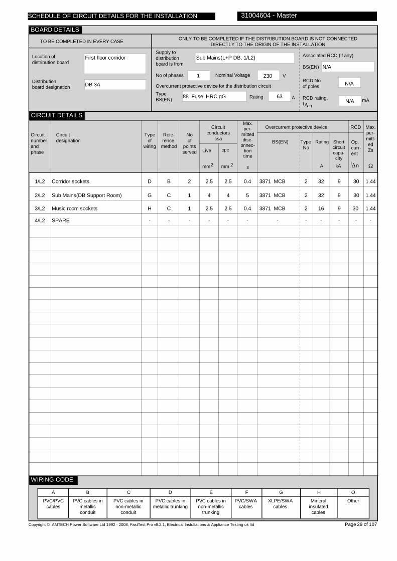
First floor corridor
DB 3A
Sub Mains(L+P DB, 1/L2)
88 Fuse HRC gG 63
1 230
N/A
N/A
N/A
1/L2
2/L2
3/L2
4/L2
Corridor sockets
Sub Mains(DB Support Room)
Music room sockets
SPARE
D
G
H
-
B
C
C
-
2
1
1
-
2.5
4
2.5
-
2.5
4
2.5
-
0.4
5
0.4
-
3871 MCB
3871 MCB
3871 MCB
-
2
2
2
-
32
32
16
-
9
9
9
-
30
30
30
-
1.44
1.44
1.44
-
Copyright © AMTECH Power Software Ltd 1992 - 2008, FastTest Pro v9.2.1, Electrical Instullations & Appliance Testing uk ltd
TO BE COMPLETED IN EVERY CASE ONLY TO BE COMPLETED IF THE DISTRIBUTION BOARD IS NOT CONNECTED DIRECTLY TO THE ORIGIN OF THE INSTALLATION
Location of distribution board
Distribution board designation
Supply to distributionboard is from
Overcurrent protective device for the distribution circuitTypeBS(EN) Rating A
No of phases Nominal Voltage V
Associated RCD (if any)
BS(EN)
RCD No of poles
RCD rating,I
mA∆ n
Circuitnumberandphase
Circuitdesignation
Typeof
wiring
Refe-rence method
Noof
pointsserved
Circuitconductors
csa
Live cpc
mm mm2 2
Max.per-
mitteddisc-
onnec-tiontime
s
Overcurrent protective device
BS(EN) Type No
Rating Shortcircuitcapa-city
RCD
Op.curr-ent
I∆n
Max.per-mitt-edZs
Ω
PVC/PVCcables
PVC cables in metallic conduit
PVC cables in non-metallic
conduit
PVC cables in metallic trunking
PVC cables in non-metallic
trunking
PVC/SWAcables
XLPE/SWAcables
Mineralinsulatedcables
Other
31004604 - Master
A B C D E F G H O
Page 29 of 107
SCHEDULE OF CIRCUIT DETAILS FOR THE INSTALLATION
CIRCUIT DETAILS
BOARD DETAILS
WIRING CODE
kAA

0.16
1.42
27
12
07270722
07270722
07270722
07270722
N/A
1/L2
2/L2
3/L2
4/L2
0.20
N/A
N/A
-
0.22
N/A
N/A
-
0.25
N/A
N/A
-
0.10
N/A
N/A
-
N/A
0.29
0.50
-
N/A
N/A
N/A
-
>10
>10
>10
-
>10
>10
>10
-
>10
>10
>10
-
ü
ü
ü
0.23
0.40
0.62
-
27 12
27 12
27 12
- -
Electrical Inspection Engineer
D. Nichols
Copyright © AMTECH Power Software Ltd 1992 - 2008, FastTest Pro v9.2.1, Electrical Instullations & Appliance Testing uk ltd
ONLY TO BE COMPLETED IF THE DISTRIBUTION BOARDIS NOT CONNECTED DIRECTLY TO THE ORIGIN OF THE
INSTALLATION
Zs
Ipf kA
Ω Operating times ofassociatedRCD (if any)
5I
(if applicable)
At I ∆ n ms
ms
N/A
TEST INSTRUMENTS (SERIAL NUMBERS) USED
Earth faultloopimpedance
Insulation resistance
Continuity
RCD
Other
Other
Circuitnumberandphase
Circuit impedances
Ω
Ring final circuits only(measured end to end)
r
(Line)
r
(Neutral)
r
(cpc)
1 2n
All circuits(At least one
columnto be completed)
R + R1 2 R 2
Insulation resistance
Line/Line
Line/Neutral
Line/Earth
Earth/Neutral
Polarity
Ω Ω Ω ΩMMMM
RCD operating times
Maximummeasuredearth fault
loop impedance
Ω msms
At
I ∆ n
Signature
Name
Position
Date of testing
31004604 - Master
Page 30 of 107
n∆
At
5I∆ n
29/07/2010
SCHEDULE OF CIRCUIT TESTS FOR THE INSTALLATION
CIRCUIT TESTS
TESTED BY
BOARD TESTS
Confirmation of Supply polarity ü

Support room
DB Support Room
Sub Mains(DB 3A, 2/L2)
3871 MCB 2 32
1 230
4293 RCD
2
30
1/L2
Support room sockets
E
B
4
2.5
1.5
0.4
60898 MCB
B
32
6
30
1.44
Copyright © AMTECH Power Software Ltd 1992 - 2008, FastTest Pro v9.2.1, Electrical Instullations & Appliance Testing uk ltd
TO BE COMPLETED IN EVERY CASE ONLY TO BE COMPLETED IF THE DISTRIBUTION BOARD IS NOT CONNECTED DIRECTLY TO THE ORIGIN OF THE INSTALLATION
Location of distribution board
Distribution board designation
Supply to distributionboard is from
Overcurrent protective device for the distribution circuitTypeBS(EN) Rating A
No of phases Nominal Voltage V
Associated RCD (if any)
BS(EN)
RCD No of poles
RCD rating,I
mA∆ n
Circuitnumberandphase
Circuitdesignation
Typeof
wiring
Refe-rence method
Noof
pointsserved
Circuitconductors
csa
Live cpc
mm mm2 2
Max.per-
mitteddisc-
onnec-tiontime
s
Overcurrent protective device
BS(EN) Type No
Rating Shortcircuitcapa-city
RCD
Op.curr-ent
I∆n
Max.per-mitt-edZs
Ω
PVC/PVCcables
PVC cables in metallic conduit
PVC cables in non-metallic
conduit
PVC cables in metallic trunking
PVC cables in non-metallic
trunking
PVC/SWAcables
XLPE/SWAcables
Mineralinsulatedcables
Other
31004604 - Master
A B C D E F G H O
Page 31 of 107
SCHEDULE OF CIRCUIT DETAILS FOR THE INSTALLATION
CIRCUIT DETAILS
BOARD DETAILS
WIRING CODE
kAA

0.40
0.58
27
12
0707070985
0707070985
0707070985
0707070985
N/A
1/L2
0.11
0.12
0.18
0.09
N/A
N/A
>10
>10
>10
ü
0.48
27 12
Electrical Inspection Engineer
D. Nichols
Copyright © AMTECH Power Software Ltd 1992 - 2008, FastTest Pro v9.2.1, Electrical Instullations & Appliance Testing uk ltd
ONLY TO BE COMPLETED IF THE DISTRIBUTION BOARDIS NOT CONNECTED DIRECTLY TO THE ORIGIN OF THE
INSTALLATION
Zs
Ipf kA
Ω Operating times ofassociatedRCD (if any)
5I
(if applicable)
At I ∆ n ms
ms
N/A
TEST INSTRUMENTS (SERIAL NUMBERS) USED
Earth faultloopimpedance
Insulation resistance
Continuity
RCD
Other
Other
Circuitnumberandphase
Circuit impedances
Ω
Ring final circuits only(measured end to end)
r
(Line)
r
(Neutral)
r
(cpc)
1 2n
All circuits(At least one
columnto be completed)
R + R1 2 R 2
Insulation resistance
Line/Line
Line/Neutral
Line/Earth
Earth/Neutral
Polarity
Ω Ω Ω ΩMMMM
RCD operating times
Maximummeasuredearth fault
loop impedance
Ω msms
At
I ∆ n
Signature
Name
Position
Date of testing
31004604 - Master
Page 32 of 107
n∆
At
5I∆ n
29/07/2010
SCHEDULE OF CIRCUIT TESTS FOR THE INSTALLATION
CIRCUIT TESTS
TESTED BY
BOARD TESTS
Confirmation of Supply polarity ü

Ground floor corridor
DB 1
Sub Mains(L+P DB, 1/L3)
88 Fuse HRC gG 63
1 230
N/A
N/A
N/A
1/L3
2/L3
3/L3
4/L3
5/L3
6/L3
7/L3
8/L3
9/L3
10/L3
11/L3
12/L3
13/L3
14/L3
15/L3
Woodwork room lights
Woodwork room lights
Boys WC & cloak room lts
Corr & cleaners lights
Headteacher & boys WC lts
Boiler house lights
Class room 1 lights
Class room 2 lights
Corridor lights
Corrid htr via time clock
BT supply
Burgular alarm
IT room fans
Sub Mains(DB IT)
CCTV supply
D
D
D
D
D
D
D
D
D
D
D
D
H
D
H
B
B
B
B
B
B
B
B
B
B
B
B
C
B
C
9
9
8
4
5
4
11
9
6
1
N/V
1
2
1
N/V
1.5
1.5
1.5
1.5
1.5
1.5
1.5
1.5
1.5
2.5
2.5
2.5
1.5
10
1.5
TRUNK
TRUNK
TRUNK
TRUNK
TRUNK
TRUNK
TRUNK
TRUNK
TRUNK
TRUNK
TRUNK
TRUNK
1.5
10
TRUNK
0.4
0.4
0.4
0.4
0.4
0.4
0.4
0.4
0.4
0.4
0.4
0.4
0.4
5
0.4
3871 MCB
3871 MCB
3871 MCB
3871 MCB
3871 MCB
3871 MCB
3871 MCB
3871 MCB
3871 MCB
3871 MCB
3871 MCB
3871 MCB
3871 MCB
60898 MCB
3871 MCB
2
2
2
2
2
2
2
2
2
2
2
2
2
B
2
10
10
10
10
10
10
10
10
10
10
10
16
16
63
32
9
9
9
9
9
9
9
9
9
9
9
9
9
6
9
N/A
N/A
N/A
N/A
N/A
N/A
N/A
N/A
N/A
N/A
N/A
N/A
N/A
N/A
N/A
3.29
3.29
3.29
3.29
3.29
3.29
3.29
3.29
3.29
3.29
3.29
2.88
2.88
0.73
1.44
Copyright © AMTECH Power Software Ltd 1992 - 2008, FastTest Pro v9.2.1, Electrical Instullations & Appliance Testing uk ltd
TO BE COMPLETED IN EVERY CASE ONLY TO BE COMPLETED IF THE DISTRIBUTION BOARD IS NOT CONNECTED DIRECTLY TO THE ORIGIN OF THE INSTALLATION
Location of distribution board
Distribution board designation
Supply to distributionboard is from
Overcurrent protective device for the distribution circuitTypeBS(EN) Rating A
No of phases Nominal Voltage V
Associated RCD (if any)
BS(EN)
RCD No of poles
RCD rating,I
mA∆ n
Circuitnumberandphase
Circuitdesignation
Typeof
wiring
Refe-rence method
Noof
pointsserved
Circuitconductors
csa
Live cpc
mm mm2 2
Max.per-
mitteddisc-
onnec-tiontime
s
Overcurrent protective device
BS(EN) Type No
Rating Shortcircuitcapa-city
RCD
Op.curr-ent
I∆n
Max.per-mitt-edZs
Ω
PVC/PVCcables
PVC cables in metallic conduit
PVC cables in non-metallic
conduit
PVC cables in metallic trunking
PVC cables in non-metallic
trunking
PVC/SWAcables
XLPE/SWAcables
Mineralinsulatedcables
Other
31004604 - Master
A B C D E F G H O
Page 33 of 107
SCHEDULE OF CIRCUIT DETAILS FOR THE INSTALLATION
CIRCUIT DETAILS
BOARD DETAILS
WIRING CODE
kAA
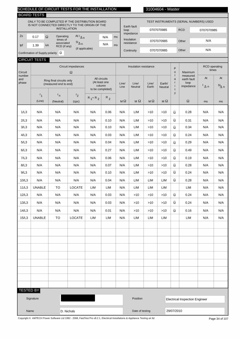
0.17
1.39
N/A
N/A
0707070985
0707070985
0707070985
0707070985
N/A
1/L3
2/L3
3/L3
4/L3
5/L3
6/L3
7/L3
8/L3
9/L3
10/L3
11/L3
12/L3
13/L3
14/L3
15/L3
N/A
N/A
N/A
N/A
N/A
N/A
N/A
N/A
N/A
N/A
UNABLE
N/A
N/A
N/A
UNABLE
N/A
N/A
N/A
N/A
N/A
N/A
N/A
N/A
N/A
N/A
TO
N/A
N/A
N/A
TO
N/A
N/A
N/A
N/A
N/A
N/A
N/A
N/A
N/A
N/A
LOCATE
N/A
N/A
N/A
LOCATE
N/A
N/A
N/A
N/A
N/A
N/A
N/A
N/A
N/A
N/A
LIM
N/A
N/A
N/A
LIM
0.06
0.10
0.10
0.03
0.04
0.27
0.06
0.07
0.10
0.04
LIM
0.03
0.03
0.01
LIM
N/A
N/A
N/A
N/A
N/A
N/A
N/A
N/A
N/A
N/A
N/A
N/A
N/A
N/A
N/A
LIM
LIM
LIM
LIM
LIM
LIM
LIM
LIM
LIM
LIM
LIM
>10
>10
>10
LIM
>10
>10
>10
>10
>10
>10
>10
>10
>10
LIM
LIM
>10
>10
>10
LIM
>10
>10
>10
>10
>10
>10
>10
>10
>10
LIM
LIM
>10
>10
>10
LIM
ü
ü
ü
ü
ü
ü
ü
ü
ü
ü
ü
ü
ü
0.28
0.31
0.34
0.24
0.29
0.49
0.19
0.28
0.24
0.28
LIM
0.24
0.24
0.16
LIM
N/A N/A
N/A N/A
N/A N/A
N/A N/A
N/A N/A
N/A N/A
N/A N/A
N/A N/A
N/A N/A
N/A N/A
N/A N/A
N/A N/A
N/A N/A
N/A N/A
N/A N/A
Electrical Inspection Engineer
D. Nichols
Copyright © AMTECH Power Software Ltd 1992 - 2008, FastTest Pro v9.2.1, Electrical Instullations & Appliance Testing uk ltd
ONLY TO BE COMPLETED IF THE DISTRIBUTION BOARDIS NOT CONNECTED DIRECTLY TO THE ORIGIN OF THE
INSTALLATION
Zs
Ipf kA
Ω Operating times ofassociatedRCD (if any)
5I
(if applicable)
At I ∆ n ms
ms
N/A
TEST INSTRUMENTS (SERIAL NUMBERS) USED
Earth faultloopimpedance
Insulation resistance
Continuity
RCD
Other
Other
Circuitnumberandphase
Circuit impedances
Ω
Ring final circuits only(measured end to end)
r
(Line)
r
(Neutral)
r
(cpc)
1 2n
All circuits(At least one
columnto be completed)
R + R1 2 R 2
Insulation resistance
Line/Line
Line/Neutral
Line/Earth
Earth/Neutral
Polarity
Ω Ω Ω ΩMMMM
RCD operating times
Maximummeasuredearth fault
loop impedance
Ω msms
At
I ∆ n
Signature
Name
Position
Date of testing
31004604 - Master
Page 34 of 107
n∆
At
5I∆ n
29/07/2010
SCHEDULE OF CIRCUIT TESTS FOR THE INSTALLATION
CIRCUIT TESTS
TESTED BY
BOARD TESTS
Confirmation of Supply polarity ü
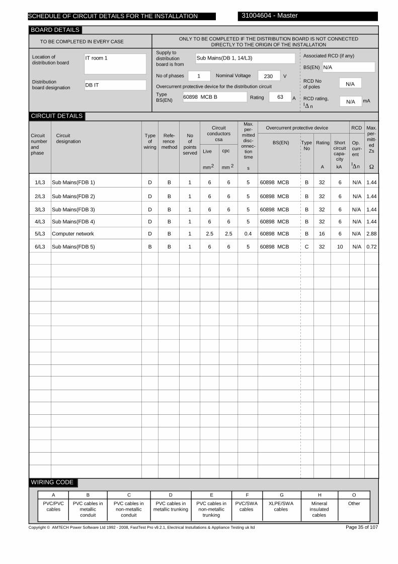
IT room 1
DB IT
Sub Mains(DB 1, 14/L3)
60898 MCB B 63
1 230
N/A
N/A
N/A
1/L3
2/L3
3/L3
4/L3
5/L3
6/L3
Sub Mains(FDB 1)
Sub Mains(FDB 2)
Sub Mains(FDB 3)
Sub Mains(FDB 4)
Computer network
Sub Mains(FDB 5)
D
D
D
D
D
B
B
B
B
B
B
B
1
1
1
1
1
1
6
6
6
6
2.5
6
6
6
6
6
2.5
6
5
5
5
5
0.4
5
60898 MCB
60898 MCB
60898 MCB
60898 MCB
60898 MCB
60898 MCB
B
B
B
B
B
C
32
32
32
32
16
32
6
6
6
6
6
10
N/A
N/A
N/A
N/A
N/A
N/A
1.44
1.44
1.44
1.44
2.88
0.72
Copyright © AMTECH Power Software Ltd 1992 - 2008, FastTest Pro v9.2.1, Electrical Instullations & Appliance Testing uk ltd
TO BE COMPLETED IN EVERY CASE ONLY TO BE COMPLETED IF THE DISTRIBUTION BOARD IS NOT CONNECTED DIRECTLY TO THE ORIGIN OF THE INSTALLATION
Location of distribution board
Distribution board designation
Supply to distributionboard is from
Overcurrent protective device for the distribution circuitTypeBS(EN) Rating A
No of phases Nominal Voltage V
Associated RCD (if any)
BS(EN)
RCD No of poles
RCD rating,I
mA∆ n
Circuitnumberandphase
Circuitdesignation
Typeof
wiring
Refe-rence method
Noof
pointsserved
Circuitconductors
csa
Live cpc
mm mm2 2
Max.per-
mitteddisc-
onnec-tiontime
s
Overcurrent protective device
BS(EN) Type No
Rating Shortcircuitcapa-city
RCD
Op.curr-ent
I∆n
Max.per-mitt-edZs
Ω
PVC/PVCcables
PVC cables in metallic conduit
PVC cables in non-metallic
conduit
PVC cables in metallic trunking
PVC cables in non-metallic
trunking
PVC/SWAcables
XLPE/SWAcables
Mineralinsulatedcables
Other
31004604 - Master
A B C D E F G H O
Page 35 of 107
SCHEDULE OF CIRCUIT DETAILS FOR THE INSTALLATION
CIRCUIT DETAILS
BOARD DETAILS
WIRING CODE
kAA

0.16
1.42
N/A
N/A
0707070985
0707070985
0707070985
0707070985
N/A
1/L3
2/L3
3/L3
4/L3
5/L3
6/L3
N/A
N/A
N/A
N/A
N/A
N/A
N/A
N/A
N/A
N/A
N/A
N/A
N/A
N/A
N/A
N/A
N/A
N/A
N/A
N/A
N/A
N/A
N/A
N/A
0.02
0.01
0.01
0.01
LIM
0.01
N/A
N/A
N/A
N/A
N/A
N/A
>10
>10
>10
>10
LIM
>10
>10
>10
>10
>10
LIM
>10
>10
>10
>10
>10
LIM
>10
ü
ü
ü
ü
ü
0.18
0.20
0.18
0.18
LIM
0.18
N/A N/A
N/A N/A
N/A N/A
N/A N/A
N/A N/A
N/A N/A
Electrical Inspection Engineer
D. Nichols
Copyright © AMTECH Power Software Ltd 1992 - 2008, FastTest Pro v9.2.1, Electrical Instullations & Appliance Testing uk ltd
ONLY TO BE COMPLETED IF THE DISTRIBUTION BOARDIS NOT CONNECTED DIRECTLY TO THE ORIGIN OF THE
INSTALLATION
Zs
Ipf kA
Ω Operating times ofassociatedRCD (if any)
5I
(if applicable)
At I ∆ n ms
ms
N/A
TEST INSTRUMENTS (SERIAL NUMBERS) USED
Earth faultloopimpedance
Insulation resistance
Continuity
RCD
Other
Other
Circuitnumberandphase
Circuit impedances
Ω
Ring final circuits only(measured end to end)
r
(Line)
r
(Neutral)
r
(cpc)
1 2n
All circuits(At least one
columnto be completed)
R + R1 2 R 2
Insulation resistance
Line/Line
Line/Neutral
Line/Earth
Earth/Neutral
Polarity
Ω Ω Ω ΩMMMM
RCD operating times
Maximummeasuredearth fault
loop impedance
Ω msms
At
I ∆ n
Signature
Name
Position
Date of testing
31004604 - Master
Page 36 of 107
n∆
At
5I∆ n
29/07/2010
SCHEDULE OF CIRCUIT TESTS FOR THE INSTALLATION
CIRCUIT TESTS
TESTED BY
BOARD TESTS
Confirmation of Supply polarity ü

IT room 1
FDB 1
Sub Mains(DB IT, 1/L3)
60898 MCB B 32
1 230
N/A
N/A
N/A
1/L3
IT room sockets
E
B
11
2.5
2.5
0.4
61009
C
32
6
30
0.72
Copyright © AMTECH Power Software Ltd 1992 - 2008, FastTest Pro v9.2.1, Electrical Instullations & Appliance Testing uk ltd
TO BE COMPLETED IN EVERY CASE ONLY TO BE COMPLETED IF THE DISTRIBUTION BOARD IS NOT CONNECTED DIRECTLY TO THE ORIGIN OF THE INSTALLATION
Location of distribution board
Distribution board designation
Supply to distributionboard is from
Overcurrent protective device for the distribution circuitTypeBS(EN) Rating A
No of phases Nominal Voltage V
Associated RCD (if any)
BS(EN)
RCD No of poles
RCD rating,I
mA∆ n
Circuitnumberandphase
Circuitdesignation
Typeof
wiring
Refe-rence method
Noof
pointsserved
Circuitconductors
csa
Live cpc
mm mm2 2
Max.per-
mitteddisc-
onnec-tiontime
s
Overcurrent protective device
BS(EN) Type No
Rating Shortcircuitcapa-city
RCD
Op.curr-ent
I∆n
Max.per-mitt-edZs
Ω
PVC/PVCcables
PVC cables in metallic conduit
PVC cables in non-metallic
conduit
PVC cables in metallic trunking
PVC cables in non-metallic
trunking
PVC/SWAcables
XLPE/SWAcables
Mineralinsulatedcables
Other
31004604 - Master
A B C D E F G H O
Page 37 of 107
SCHEDULE OF CIRCUIT DETAILS FOR THE INSTALLATION
CIRCUIT DETAILS
BOARD DETAILS
WIRING CODE
kAA

0.18
1.34
N/A
N/A
0707070985
0707070985
0707070985
0707070985
N/A
1/L3
0.26
0.25
0.21
0.10
N/A
N/A
>10
>10
>10
ü
0.38
67 21
Electrical Inspection Engineer
D. Nichols
Copyright © AMTECH Power Software Ltd 1992 - 2008, FastTest Pro v9.2.1, Electrical Instullations & Appliance Testing uk ltd
ONLY TO BE COMPLETED IF THE DISTRIBUTION BOARDIS NOT CONNECTED DIRECTLY TO THE ORIGIN OF THE
INSTALLATION
Zs
Ipf kA
Ω Operating times ofassociatedRCD (if any)
5I
(if applicable)
At I ∆ n ms
ms
N/A
TEST INSTRUMENTS (SERIAL NUMBERS) USED
Earth faultloopimpedance
Insulation resistance
Continuity
RCD
Other
Other
Circuitnumberandphase
Circuit impedances
Ω
Ring final circuits only(measured end to end)
r
(Line)
r
(Neutral)
r
(cpc)
1 2n
All circuits(At least one
columnto be completed)
R + R1 2 R 2
Insulation resistance
Line/Line
Line/Neutral
Line/Earth
Earth/Neutral
Polarity
Ω Ω Ω ΩMMMM
RCD operating times
Maximummeasuredearth fault
loop impedance
Ω msms
At
I ∆ n
Signature
Name
Position
Date of testing
31004604 - Master
Page 38 of 107
n∆
At
5I∆ n
29/07/2010
SCHEDULE OF CIRCUIT TESTS FOR THE INSTALLATION
CIRCUIT TESTS
TESTED BY
BOARD TESTS
Confirmation of Supply polarity ü

IT room 1
FDB 2
Sub Mains(DB IT, 2/L3)
60898 MCB B 32
1 230
N/A
N/A
N/A
1/L3
FDB 2
E
B
7
2.5
1.5
0.4
61009
C
32
6
30
0.72
Copyright © AMTECH Power Software Ltd 1992 - 2008, FastTest Pro v9.2.1, Electrical Instullations & Appliance Testing uk ltd
TO BE COMPLETED IN EVERY CASE ONLY TO BE COMPLETED IF THE DISTRIBUTION BOARD IS NOT CONNECTED DIRECTLY TO THE ORIGIN OF THE INSTALLATION
Location of distribution board
Distribution board designation
Supply to distributionboard is from
Overcurrent protective device for the distribution circuitTypeBS(EN) Rating A
No of phases Nominal Voltage V
Associated RCD (if any)
BS(EN)
RCD No of poles
RCD rating,I
mA∆ n
Circuitnumberandphase
Circuitdesignation
Typeof
wiring
Refe-rence method
Noof
pointsserved
Circuitconductors
csa
Live cpc
mm mm2 2
Max.per-
mitteddisc-
onnec-tiontime
s
Overcurrent protective device
BS(EN) Type No
Rating Shortcircuitcapa-city
RCD
Op.curr-ent
I∆n
Max.per-mitt-edZs
Ω
PVC/PVCcables
PVC cables in metallic conduit
PVC cables in non-metallic
conduit
PVC cables in metallic trunking
PVC cables in non-metallic
trunking
PVC/SWAcables
XLPE/SWAcables
Mineralinsulatedcables
Other
31004604 - Master
A B C D E F G H O
Page 39 of 107
SCHEDULE OF CIRCUIT DETAILS FOR THE INSTALLATION
CIRCUIT DETAILS
BOARD DETAILS
WIRING CODE
kAA
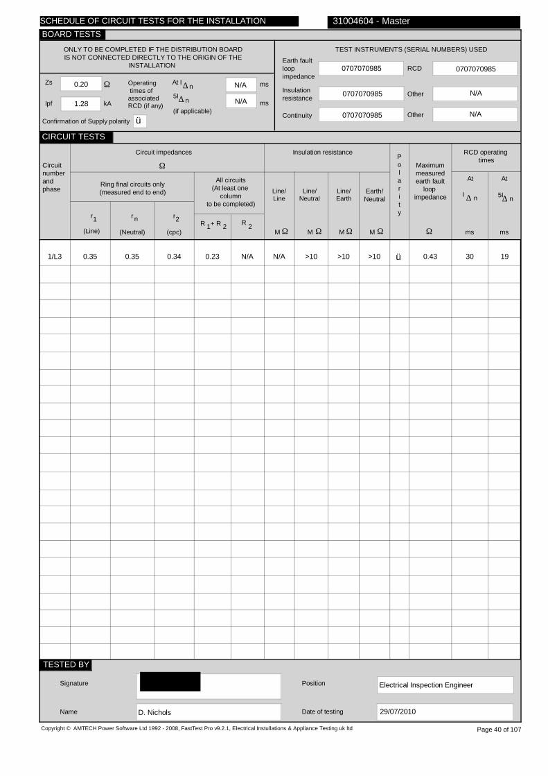
0.20
1.28
N/A
N/A
0707070985
0707070985
0707070985
0707070985
N/A
1/L3
0.35
0.35
0.34
0.23
N/A
N/A
>10
>10
>10
ü
0.43
30 19
Electrical Inspection Engineer
D. Nichols
Copyright © AMTECH Power Software Ltd 1992 - 2008, FastTest Pro v9.2.1, Electrical Instullations & Appliance Testing uk ltd
ONLY TO BE COMPLETED IF THE DISTRIBUTION BOARDIS NOT CONNECTED DIRECTLY TO THE ORIGIN OF THE
INSTALLATION
Zs
Ipf kA
Ω Operating times ofassociatedRCD (if any)
5I
(if applicable)
At I ∆ n ms
ms
N/A
TEST INSTRUMENTS (SERIAL NUMBERS) USED
Earth faultloopimpedance
Insulation resistance
Continuity
RCD
Other
Other
Circuitnumberandphase
Circuit impedances
Ω
Ring final circuits only(measured end to end)
r
(Line)
r
(Neutral)
r
(cpc)
1 2n
All circuits(At least one
columnto be completed)
R + R1 2 R 2
Insulation resistance
Line/Line
Line/Neutral
Line/Earth
Earth/Neutral
Polarity
Ω Ω Ω ΩMMMM
RCD operating times
Maximummeasuredearth fault
loop impedance
Ω msms
At
I ∆ n
Signature
Name
Position
Date of testing
31004604 - Master
Page 40 of 107
n∆
At
5I∆ n
29/07/2010
SCHEDULE OF CIRCUIT TESTS FOR THE INSTALLATION
CIRCUIT TESTS
TESTED BY
BOARD TESTS
Confirmation of Supply polarity ü

IT room 1
FDB 3
Sub Mains(DB IT, 3/L3)
60898 MCB B 32
1 230
N/A
N/A
N/A
1/L3
FDB 3
E
B
7
2.5
1.5
0.4
61009
C
32
6
30
0.72
Copyright © AMTECH Power Software Ltd 1992 - 2008, FastTest Pro v9.2.1, Electrical Instullations & Appliance Testing uk ltd
TO BE COMPLETED IN EVERY CASE ONLY TO BE COMPLETED IF THE DISTRIBUTION BOARD IS NOT CONNECTED DIRECTLY TO THE ORIGIN OF THE INSTALLATION
Location of distribution board
Distribution board designation
Supply to distributionboard is from
Overcurrent protective device for the distribution circuitTypeBS(EN) Rating A
No of phases Nominal Voltage V
Associated RCD (if any)
BS(EN)
RCD No of poles
RCD rating,I
mA∆ n
Circuitnumberandphase
Circuitdesignation
Typeof
wiring
Refe-rence method
Noof
pointsserved
Circuitconductors
csa
Live cpc
mm mm2 2
Max.per-
mitteddisc-
onnec-tiontime
s
Overcurrent protective device
BS(EN) Type No
Rating Shortcircuitcapa-city
RCD
Op.curr-ent
I∆n
Max.per-mitt-edZs
Ω
PVC/PVCcables
PVC cables in metallic conduit
PVC cables in non-metallic
conduit
PVC cables in metallic trunking
PVC cables in non-metallic
trunking
PVC/SWAcables
XLPE/SWAcables
Mineralinsulatedcables
Other
31004604 - Master
A B C D E F G H O
Page 41 of 107
SCHEDULE OF CIRCUIT DETAILS FOR THE INSTALLATION
CIRCUIT DETAILS
BOARD DETAILS
WIRING CODE
kAA

0.18
1.28
N/A
N/A
0707070985
0707070985
0707070985
0707070985
N/A
1/L3
0.44
0.44
0.44
0.21
N/A
N/A
>10
>10
>10
ü
0.47
>300 >40
Electrical Inspection Engineer
D. Nichols
Copyright © AMTECH Power Software Ltd 1992 - 2008, FastTest Pro v9.2.1, Electrical Instullations & Appliance Testing uk ltd
ONLY TO BE COMPLETED IF THE DISTRIBUTION BOARDIS NOT CONNECTED DIRECTLY TO THE ORIGIN OF THE
INSTALLATION
Zs
Ipf kA
Ω Operating times ofassociatedRCD (if any)
5I
(if applicable)
At I ∆ n ms
ms
N/A
TEST INSTRUMENTS (SERIAL NUMBERS) USED
Earth faultloopimpedance
Insulation resistance
Continuity
RCD
Other
Other
Circuitnumberandphase
Circuit impedances
Ω
Ring final circuits only(measured end to end)
r
(Line)
r
(Neutral)
r
(cpc)
1 2n
All circuits(At least one
columnto be completed)
R + R1 2 R 2
Insulation resistance
Line/Line
Line/Neutral
Line/Earth
Earth/Neutral
Polarity
Ω Ω Ω ΩMMMM
RCD operating times
Maximummeasuredearth fault
loop impedance
Ω msms
At
I ∆ n
Signature
Name
Position
Date of testing
31004604 - Master
Page 42 of 107
n∆
At
5I∆ n
29/07/2010
SCHEDULE OF CIRCUIT TESTS FOR THE INSTALLATION
CIRCUIT TESTS
TESTED BY
BOARD TESTS
Confirmation of Supply polarity ü

IT room 1
FDB 4
Sub Mains(DB IT, 4/L3)
60898 MCB B 32
1 230
N/A
N/A
N/A
1/L3
IT room 1
E
B
7
2.5
1.5
0.4
61009
C
32
6
30
0.72
Copyright © AMTECH Power Software Ltd 1992 - 2008, FastTest Pro v9.2.1, Electrical Instullations & Appliance Testing uk ltd
TO BE COMPLETED IN EVERY CASE ONLY TO BE COMPLETED IF THE DISTRIBUTION BOARD IS NOT CONNECTED DIRECTLY TO THE ORIGIN OF THE INSTALLATION
Location of distribution board
Distribution board designation
Supply to distributionboard is from
Overcurrent protective device for the distribution circuitTypeBS(EN) Rating A
No of phases Nominal Voltage V
Associated RCD (if any)
BS(EN)
RCD No of poles
RCD rating,I
mA∆ n
Circuitnumberandphase
Circuitdesignation
Typeof
wiring
Refe-rence method
Noof
pointsserved
Circuitconductors
csa
Live cpc
mm mm2 2
Max.per-
mitteddisc-
onnec-tiontime
s
Overcurrent protective device
BS(EN) Type No
Rating Shortcircuitcapa-city
RCD
Op.curr-ent
I∆n
Max.per-mitt-edZs
Ω
PVC/PVCcables
PVC cables in metallic conduit
PVC cables in non-metallic
conduit
PVC cables in metallic trunking
PVC cables in non-metallic
trunking
PVC/SWAcables
XLPE/SWAcables
Mineralinsulatedcables
Other
31004604 - Master
A B C D E F G H O
Page 43 of 107
SCHEDULE OF CIRCUIT DETAILS FOR THE INSTALLATION
CIRCUIT DETAILS
BOARD DETAILS
WIRING CODE
kAA
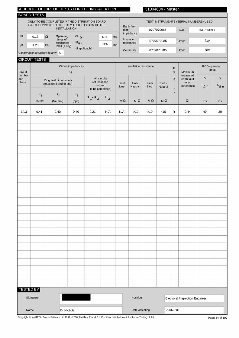
0.18
1.28
N/A
N/A
0707070985
0707070985
0707070985
0707070985
N/A
1/L3
0.41
0.40
0.40
0.21
N/A
N/A
>10
>10
>10
ü
0.44
49 20
Electrical Inspection Engineer
D. Nichols
Copyright © AMTECH Power Software Ltd 1992 - 2008, FastTest Pro v9.2.1, Electrical Instullations & Appliance Testing uk ltd
ONLY TO BE COMPLETED IF THE DISTRIBUTION BOARDIS NOT CONNECTED DIRECTLY TO THE ORIGIN OF THE
INSTALLATION
Zs
Ipf kA
Ω Operating times ofassociatedRCD (if any)
5I
(if applicable)
At I ∆ n ms
ms
N/A
TEST INSTRUMENTS (SERIAL NUMBERS) USED
Earth faultloopimpedance
Insulation resistance
Continuity
RCD
Other
Other
Circuitnumberandphase
Circuit impedances
Ω
Ring final circuits only(measured end to end)
r
(Line)
r
(Neutral)
r
(cpc)
1 2n
All circuits(At least one
columnto be completed)
R + R1 2 R 2
Insulation resistance
Line/Line
Line/Neutral
Line/Earth
Earth/Neutral
Polarity
Ω Ω Ω ΩMMMM
RCD operating times
Maximummeasuredearth fault
loop impedance
Ω msms
At
I ∆ n
Signature
Name
Position
Date of testing
31004604 - Master
Page 44 of 107
n∆
At
5I∆ n
29/07/2010
SCHEDULE OF CIRCUIT TESTS FOR THE INSTALLATION
CIRCUIT TESTS
TESTED BY
BOARD TESTS
Confirmation of Supply polarity ü

IT room 1
FDB 5
Sub Mains(DB IT, 6/L3)
60898 MCB C 32
1 230
4293 RCD
2
30
1/L3
IT room sockets
E
B
7
2.5
1.5
0.4
4293
2
32
6
30
1.03
Copyright © AMTECH Power Software Ltd 1992 - 2008, FastTest Pro v9.2.1, Electrical Instullations & Appliance Testing uk ltd
TO BE COMPLETED IN EVERY CASE ONLY TO BE COMPLETED IF THE DISTRIBUTION BOARD IS NOT CONNECTED DIRECTLY TO THE ORIGIN OF THE INSTALLATION
Location of distribution board
Distribution board designation
Supply to distributionboard is from
Overcurrent protective device for the distribution circuitTypeBS(EN) Rating A
No of phases Nominal Voltage V
Associated RCD (if any)
BS(EN)
RCD No of poles
RCD rating,I
mA∆ n
Circuitnumberandphase
Circuitdesignation
Typeof
wiring
Refe-rence method
Noof
pointsserved
Circuitconductors
csa
Live cpc
mm mm2 2
Max.per-
mitteddisc-
onnec-tiontime
s
Overcurrent protective device
BS(EN) Type No
Rating Shortcircuitcapa-city
RCD
Op.curr-ent
I∆n
Max.per-mitt-edZs
Ω
PVC/PVCcables
PVC cables in metallic conduit
PVC cables in non-metallic
conduit
PVC cables in metallic trunking
PVC cables in non-metallic
trunking
PVC/SWAcables
XLPE/SWAcables
Mineralinsulatedcables
Other
31004604 - Master
A B C D E F G H O
Page 45 of 107
SCHEDULE OF CIRCUIT DETAILS FOR THE INSTALLATION
CIRCUIT DETAILS
BOARD DETAILS
WIRING CODE
kAA

0.18
1.41
N/A
N/A
0707070985
0707070985
0707070985
0707070985
N/A
1/L3
0.27
0.28
0.40
0.24
N/A
N/A
>10
>10
>10
ü
0.49
64 23
Electrical Inspection Engineer
D. Nichols
Copyright © AMTECH Power Software Ltd 1992 - 2008, FastTest Pro v9.2.1, Electrical Instullations & Appliance Testing uk ltd
ONLY TO BE COMPLETED IF THE DISTRIBUTION BOARDIS NOT CONNECTED DIRECTLY TO THE ORIGIN OF THE
INSTALLATION
Zs
Ipf kA
Ω Operating times ofassociatedRCD (if any)
5I
(if applicable)
At I ∆ n ms
ms
N/A
TEST INSTRUMENTS (SERIAL NUMBERS) USED
Earth faultloopimpedance
Insulation resistance
Continuity
RCD
Other
Other
Circuitnumberandphase
Circuit impedances
Ω
Ring final circuits only(measured end to end)
r
(Line)
r
(Neutral)
r
(cpc)
1 2n
All circuits(At least one
columnto be completed)
R + R1 2 R 2
Insulation resistance
Line/Line
Line/Neutral
Line/Earth
Earth/Neutral
Polarity
Ω Ω Ω ΩMMMM
RCD operating times
Maximummeasuredearth fault
loop impedance
Ω msms
At
I ∆ n
Signature
Name
Position
Date of testing
31004604 - Master
Page 46 of 107
n∆
At
5I∆ n
29/07/2010
SCHEDULE OF CIRCUIT TESTS FOR THE INSTALLATION
CIRCUIT TESTS
TESTED BY
BOARD TESTS
Confirmation of Supply polarity ü

Ground floor corridor
DB 1A
Sub Mains(L+P DB, 1/L3)
88 Fuse HRC gG 63
1 230
4293 RCD
2
30
1/L3
2/L3
3/L3
4/L3
Corr & dep head
Room 2 sockets
Cloak skts & boys h'dryer
Sub Mains(DB Meeting Room)
D
D
D
G
B
B
B
C
10
4
5
1
2.5
2.5
2.5
6
TRUNK
TRUNK
TRUNK
6
0.4
0.4
0.4
0.4
3871 MCB
3871 MCB
60898 MCB
3871 MCB
2
2
B
1
32
32
32
32
9
9
9
6
30
30
30
30
1.44
1.44
1.44
1.80
Copyright © AMTECH Power Software Ltd 1992 - 2008, FastTest Pro v9.2.1, Electrical Instullations & Appliance Testing uk ltd
TO BE COMPLETED IN EVERY CASE ONLY TO BE COMPLETED IF THE DISTRIBUTION BOARD IS NOT CONNECTED DIRECTLY TO THE ORIGIN OF THE INSTALLATION
Location of distribution board
Distribution board designation
Supply to distributionboard is from
Overcurrent protective device for the distribution circuitTypeBS(EN) Rating A
No of phases Nominal Voltage V
Associated RCD (if any)
BS(EN)
RCD No of poles
RCD rating,I
mA∆ n
Circuitnumberandphase
Circuitdesignation
Typeof
wiring
Refe-rence method
Noof
pointsserved
Circuitconductors
csa
Live cpc
mm mm2 2
Max.per-
mitteddisc-
onnec-tiontime
s
Overcurrent protective device
BS(EN) Type No
Rating Shortcircuitcapa-city
RCD
Op.curr-ent
I∆n
Max.per-mitt-edZs
Ω
PVC/PVCcables
PVC cables in metallic conduit
PVC cables in non-metallic
conduit
PVC cables in metallic trunking
PVC cables in non-metallic
trunking
PVC/SWAcables
XLPE/SWAcables
Mineralinsulatedcables
Other
31004604 - Master
A B C D E F G H O
Page 47 of 107
SCHEDULE OF CIRCUIT DETAILS FOR THE INSTALLATION
CIRCUIT DETAILS
BOARD DETAILS
WIRING CODE
kAA
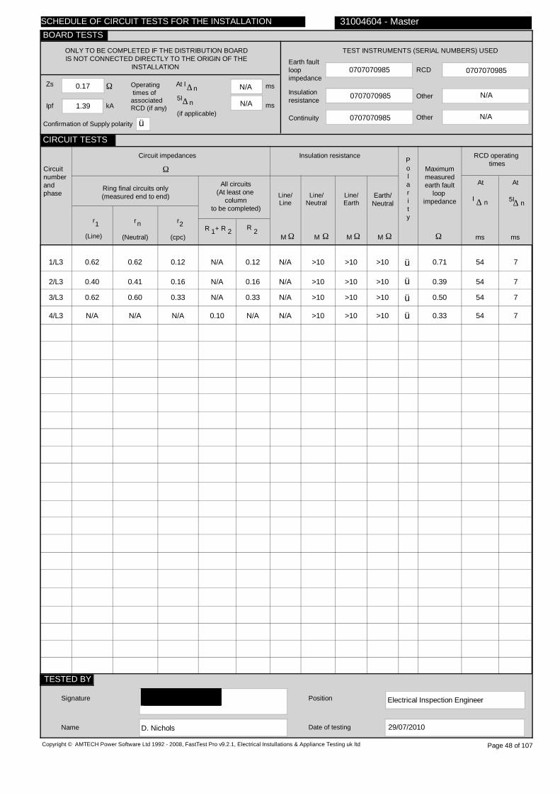
0.17
1.39
N/A
N/A
0707070985
0707070985
0707070985
0707070985
N/A
1/L3
2/L3
3/L3
4/L3
0.62
0.40
0.62
N/A
0.62
0.41
0.60
N/A
0.12
0.16
0.33
N/A
N/A
N/A
N/A
0.10
0.12
0.16
0.33
N/A
N/A
N/A
N/A
N/A
>10
>10
>10
>10
>10
>10
>10
>10
>10
>10
>10
>10
ü
ü
ü
ü
0.71
0.39
0.50
0.33
54 7
54 7
54 7
54 7
Electrical Inspection Engineer
D. Nichols
Copyright © AMTECH Power Software Ltd 1992 - 2008, FastTest Pro v9.2.1, Electrical Instullations & Appliance Testing uk ltd
ONLY TO BE COMPLETED IF THE DISTRIBUTION BOARDIS NOT CONNECTED DIRECTLY TO THE ORIGIN OF THE
INSTALLATION
Zs
Ipf kA
Ω Operating times ofassociatedRCD (if any)
5I
(if applicable)
At I ∆ n ms
ms
N/A
TEST INSTRUMENTS (SERIAL NUMBERS) USED
Earth faultloopimpedance
Insulation resistance
Continuity
RCD
Other
Other
Circuitnumberandphase
Circuit impedances
Ω
Ring final circuits only(measured end to end)
r
(Line)
r
(Neutral)
r
(cpc)
1 2n
All circuits(At least one
columnto be completed)
R + R1 2 R 2
Insulation resistance
Line/Line
Line/Neutral
Line/Earth
Earth/Neutral
Polarity
Ω Ω Ω ΩMMMM
RCD operating times
Maximummeasuredearth fault
loop impedance
Ω msms
At
I ∆ n
Signature
Name
Position
Date of testing
31004604 - Master
Page 48 of 107
n∆
At
5I∆ n
29/07/2010
SCHEDULE OF CIRCUIT TESTS FOR THE INSTALLATION
CIRCUIT TESTS
TESTED BY
BOARD TESTS
Confirmation of Supply polarity ü
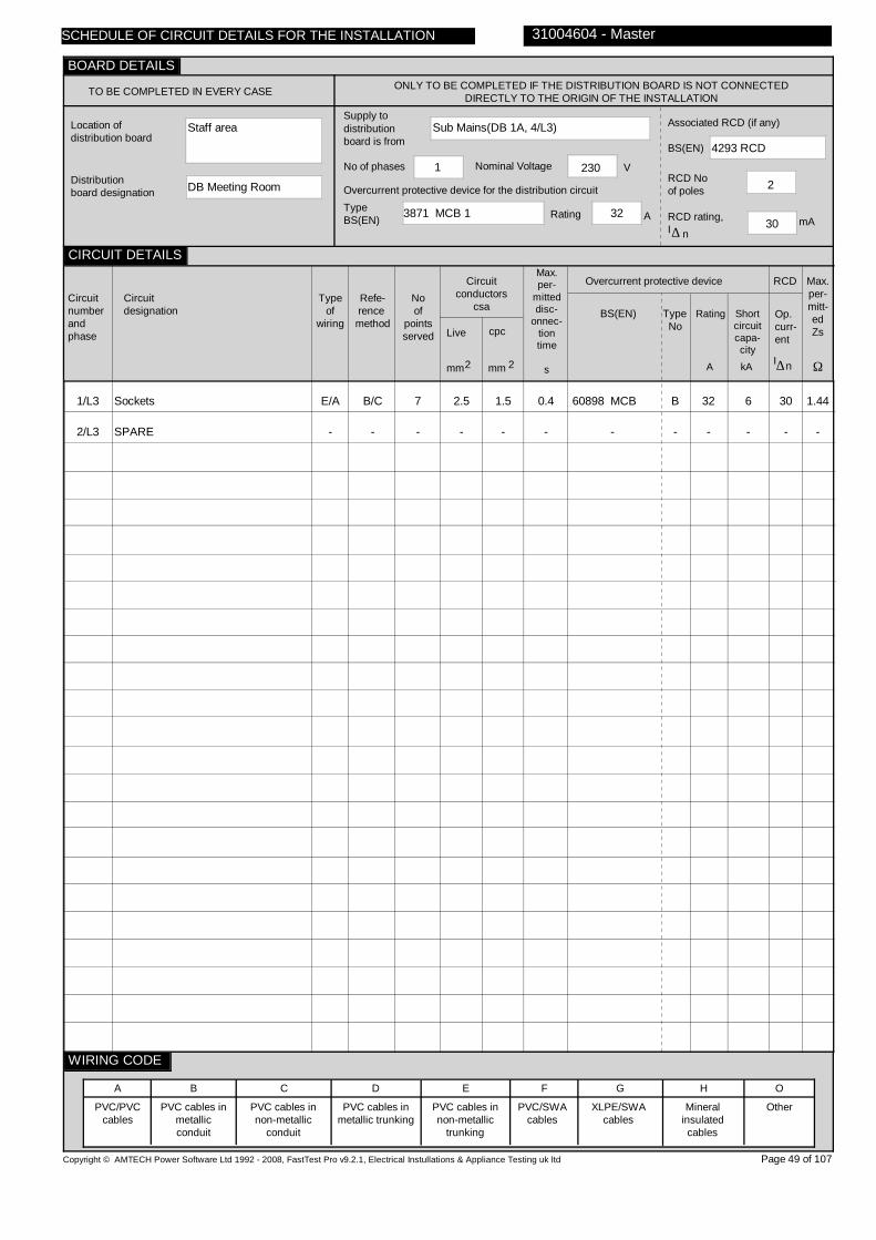
Staff area
DB Meeting Room
Sub Mains(DB 1A, 4/L3)
3871 MCB 1 32
1 230
4293 RCD
2
30
1/L3
2/L3
Sockets
SPARE
E/A
-
B/C
-
7
-
2.5
-
1.5
-
0.4
-
60898 MCB
-
B
-
32
-
6
-
30
-
1.44
-
Copyright © AMTECH Power Software Ltd 1992 - 2008, FastTest Pro v9.2.1, Electrical Instullations & Appliance Testing uk ltd
TO BE COMPLETED IN EVERY CASE ONLY TO BE COMPLETED IF THE DISTRIBUTION BOARD IS NOT CONNECTED DIRECTLY TO THE ORIGIN OF THE INSTALLATION
Location of distribution board
Distribution board designation
Supply to distributionboard is from
Overcurrent protective device for the distribution circuitTypeBS(EN) Rating A
No of phases Nominal Voltage V
Associated RCD (if any)
BS(EN)
RCD No of poles
RCD rating,I
mA∆ n
Circuitnumberandphase
Circuitdesignation
Typeof
wiring
Refe-rence method
Noof
pointsserved
Circuitconductors
csa
Live cpc
mm mm2 2
Max.per-
mitteddisc-
onnec-tiontime
s
Overcurrent protective device
BS(EN) Type No
Rating Shortcircuitcapa-city
RCD
Op.curr-ent
I∆n
Max.per-mitt-edZs
Ω
PVC/PVCcables
PVC cables in metallic conduit
PVC cables in non-metallic
conduit
PVC cables in metallic trunking
PVC cables in non-metallic
trunking
PVC/SWAcables
XLPE/SWAcables
Mineralinsulatedcables
Other
31004604 - Master
A B C D E F G H O
Page 49 of 107
SCHEDULE OF CIRCUIT DETAILS FOR THE INSTALLATION
CIRCUIT DETAILS
BOARD DETAILS
WIRING CODE
kAA
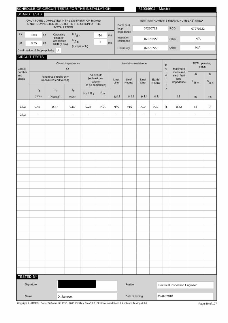
0.33
0.75
54
7
07270722
07270722
07270722
07270722
N/A
1/L3
2/L3
0.47
-
0.47
-
0.60
-
0.26
-
N/A
-
N/A
-
>10
-
>10
-
>10
-
ü
0.82
-
54 7
- -
Electrical Inspection Engineer
D. Jameson
Copyright © AMTECH Power Software Ltd 1992 - 2008, FastTest Pro v9.2.1, Electrical Instullations & Appliance Testing uk ltd
ONLY TO BE COMPLETED IF THE DISTRIBUTION BOARDIS NOT CONNECTED DIRECTLY TO THE ORIGIN OF THE
INSTALLATION
Zs
Ipf kA
Ω Operating times ofassociatedRCD (if any)
5I
(if applicable)
At I ∆ n ms
ms
N/A
TEST INSTRUMENTS (SERIAL NUMBERS) USED
Earth faultloopimpedance
Insulation resistance
Continuity
RCD
Other
Other
Circuitnumberandphase
Circuit impedances
Ω
Ring final circuits only(measured end to end)
r
(Line)
r
(Neutral)
r
(cpc)
1 2n
All circuits(At least one
columnto be completed)
R + R1 2 R 2
Insulation resistance
Line/Line
Line/Neutral
Line/Earth
Earth/Neutral
Polarity
Ω Ω Ω ΩMMMM
RCD operating times
Maximummeasuredearth fault
loop impedance
Ω msms
At
I ∆ n
Signature
Name
Position
Date of testing
31004604 - Master
Page 50 of 107
n∆
At
5I∆ n
29/07/2010
SCHEDULE OF CIRCUIT TESTS FOR THE INSTALLATION
CIRCUIT TESTS
TESTED BY
BOARD TESTS
Confirmation of Supply polarity ü

First floor corridor
DB 4
Sub Mains(L+P DB, 2/L3)
88 Fuse HRC gG 63
1 230
N/A
N/A
N/A
1/L3
2/L3
3/L3
4/L3
5/L3
6/L3
7/L3
8/L3
9/L3
10/L3
11/L3
12/L3
13/L3
14/L3
15/L3
Corridors lights
Stairs/English room lts
Lab 2 lights
Lab 2 lights
Lab 2 & prep lights
Room 10 lights
Room 9 lights
Library lights
Library lights
Water heater
Sub Mains(Lab 2 FDB)
Fume cupboard
SPARE
SPARE
SPARE
D
D
D
D
D
D
D
D
D
D
D
H
-
-
-
B
B
B
B
B
B
B
B
B
B
B
C
-
-
-
11
6
4
4
5
6
6
7
8
1
1
1
-
-
-
1.5
1.5
1.5
1.5
1.5
1.5
1.5
1.5
1.5
2.5
6
1.5
-
-
-
TRUNK
TRUNK
TRUNK
TRUNK
TRUNK
TRUNK
TRUNK
TRUNK
TRUNK
TRUNK
TRUNK
1.5
-
-
-
0.4
0.4
0.4
0.4
0.4
0.4
0.4
0.4
0.4
0.4
0.4
0.4
-
-
-
3871 MCB
3871 MCB
3871 MCB
3871 MCB
3871 MCB
3871 MCB
3871 MCB
3871 MCB
3871 MCB
3871 MCB
3871 MCB
3871 MCB
-
-
-
2
2
2
2
2
2
2
2
2
2
2
2
-
-
-
10
10
10
10
10
10
10
10
10
16
32
16
-
-
-
9
9
9
9
9
9
9
9
9
9
9
9
-
-
-
N/A
N/A
N/A
N/A
N/A
N/A
N/A
N/A
N/A
N/A
N/A
N/A
-
-
-
3.29
3.29
3.29
3.29
3.29
3.29
3.29
3.29
3.29
2.88
1.44
2.88
-
-
-
Copyright © AMTECH Power Software Ltd 1992 - 2008, FastTest Pro v9.2.1, Electrical Instullations & Appliance Testing uk ltd
TO BE COMPLETED IN EVERY CASE ONLY TO BE COMPLETED IF THE DISTRIBUTION BOARD IS NOT CONNECTED DIRECTLY TO THE ORIGIN OF THE INSTALLATION
Location of distribution board
Distribution board designation
Supply to distributionboard is from
Overcurrent protective device for the distribution circuitTypeBS(EN) Rating A
No of phases Nominal Voltage V
Associated RCD (if any)
BS(EN)
RCD No of poles
RCD rating,I
mA∆ n
Circuitnumberandphase
Circuitdesignation
Typeof
wiring
Refe-rence method
Noof
pointsserved
Circuitconductors
csa
Live cpc
mm mm2 2
Max.per-
mitteddisc-
onnec-tiontime
s
Overcurrent protective device
BS(EN) Type No
Rating Shortcircuitcapa-city
RCD
Op.curr-ent
I∆n
Max.per-mitt-edZs
Ω
PVC/PVCcables
PVC cables in metallic conduit
PVC cables in non-metallic
conduit
PVC cables in metallic trunking
PVC cables in non-metallic
trunking
PVC/SWAcables
XLPE/SWAcables
Mineralinsulatedcables
Other
31004604 - Master
A B C D E F G H O
Page 51 of 107
SCHEDULE OF CIRCUIT DETAILS FOR THE INSTALLATION
CIRCUIT DETAILS
BOARD DETAILS
WIRING CODE
kAA
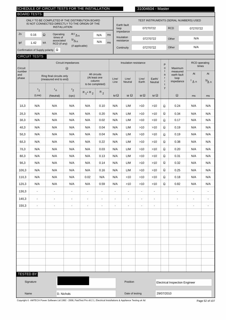
0.16
1.42
N/A
N/A
07270722
07270722
07270722
07270722
N/A
1/L3
2/L3
3/L3
4/L3
5/L3
6/L3
7/L3
8/L3
9/L3
10/L3
11/L3
12/L3
13/L3
14/L3
15/L3
N/A
N/A
N/A
N/A
N/A
N/A
N/A
N/A
N/A
N/A
N/A
N/A
-
-
-
N/A
N/A
N/A
N/A
N/A
N/A
N/A
N/A
N/A
N/A
N/A
N/A
-
-
-
N/A
N/A
N/A
N/A
N/A
N/A
N/A
N/A
N/A
N/A
N/A
N/A
-
-
-
N/A
N/A
N/A
N/A
N/A
N/A
N/A
N/A
N/A
N/A
0.02
N/A
-
-
-
0.10
0.20
0.02
0.04
0.04
0.22
0.03
0.13
0.14
0.16
N/A
0.59
-
-
-
N/A
N/A
N/A
N/A
N/A
N/A
N/A
N/A
N/A
N/A
N/A
N/A
-
-
-
LIM
LIM
LIM
LIM
LIM
LIM
LIM
LIM
LIM
LIM
>10
>10
-
-
-
>10
>10
>10
>10
>10
>10
>10
>10
>10
>10
>10
>10
-
-
-
>10
>10
>10
>10
>10
>10
>10
>10
>10
>10
>10
>10
-
-
-
ü
ü
ü
ü
ü
ü
ü
ü
ü
ü
ü
ü
0.24
0.34
0.17
0.19
0.19
0.38
0.20
0.31
0.32
0.25
0.18
0.82
-
-
-
N/A N/A
N/A N/A
N/A N/A
N/A N/A
N/A N/A
N/A N/A
N/A N/A
N/A N/A
N/A N/A
N/A N/A
N/A N/A
N/A N/A
- -
- -
- -
Electrical Inspection Engineer
D. Nichols
Copyright © AMTECH Power Software Ltd 1992 - 2008, FastTest Pro v9.2.1, Electrical Instullations & Appliance Testing uk ltd
ONLY TO BE COMPLETED IF THE DISTRIBUTION BOARDIS NOT CONNECTED DIRECTLY TO THE ORIGIN OF THE
INSTALLATION
Zs
Ipf kA
Ω Operating times ofassociatedRCD (if any)
5I
(if applicable)
At I ∆ n ms
ms
N/A
TEST INSTRUMENTS (SERIAL NUMBERS) USED
Earth faultloopimpedance
Insulation resistance
Continuity
RCD
Other
Other
Circuitnumberandphase
Circuit impedances
Ω
Ring final circuits only(measured end to end)
r
(Line)
r
(Neutral)
r
(cpc)
1 2n
All circuits(At least one
columnto be completed)
R + R1 2 R 2
Insulation resistance
Line/Line
Line/Neutral
Line/Earth
Earth/Neutral
Polarity
Ω Ω Ω ΩMMMM
RCD operating times
Maximummeasuredearth fault
loop impedance
Ω msms
At
I ∆ n
Signature
Name
Position
Date of testing
31004604 - Master
Page 52 of 107
n∆
At
5I∆ n
29/07/2010
SCHEDULE OF CIRCUIT TESTS FOR THE INSTALLATION
CIRCUIT TESTS
TESTED BY
BOARD TESTS
Confirmation of Supply polarity ü

First floor corridor
DB 4A
Sub Mains(L+P DB, 2/L3)
88 Fuse HRC gG 63
1 230
N/A
N/A
N/A
1/L3
2/L3
3/L3
4/L3
5/L3
6/L3
7/L3
Class 9-10, English skts
Library, English sockets
Prep room sockets
Room 5 dado sockets
Room 9 dado sockets
Room 9 dado sockets
SPARE
D
D
D
G
E
E
-
B
B
B
C
B
B
-
7
15
3
4
7
7
-
2.5
2.5
2.5
2.5
2.5
2.5
-
1.5
1.5
TRUNK
SWA
1.5
1.5
-
0.4
0.4
0.4
0.4
0.4
0.4
-
61009
61009
61009
61009
61009
61009
-
C
C
C
C
C
C
-
32
32
32
20
32
32
-
10
10
10
10
10
10
-
30
30
30
30
30
30
-
0.72
0.72
0.72
1.15
0.72
0.72
-
Copyright © AMTECH Power Software Ltd 1992 - 2008, FastTest Pro v9.2.1, Electrical Instullations & Appliance Testing uk ltd
TO BE COMPLETED IN EVERY CASE ONLY TO BE COMPLETED IF THE DISTRIBUTION BOARD IS NOT CONNECTED DIRECTLY TO THE ORIGIN OF THE INSTALLATION
Location of distribution board
Distribution board designation
Supply to distributionboard is from
Overcurrent protective device for the distribution circuitTypeBS(EN) Rating A
No of phases Nominal Voltage V
Associated RCD (if any)
BS(EN)
RCD No of poles
RCD rating,I
mA∆ n
Circuitnumberandphase
Circuitdesignation
Typeof
wiring
Refe-rence method
Noof
pointsserved
Circuitconductors
csa
Live cpc
mm mm2 2
Max.per-
mitteddisc-
onnec-tiontime
s
Overcurrent protective device
BS(EN) Type No
Rating Shortcircuitcapa-city
RCD
Op.curr-ent
I∆n
Max.per-mitt-edZs
Ω
PVC/PVCcables
PVC cables in metallic conduit
PVC cables in non-metallic
conduit
PVC cables in metallic trunking
PVC cables in non-metallic
trunking
PVC/SWAcables
XLPE/SWAcables
Mineralinsulatedcables
Other
31004604 - Master
A B C D E F G H O
Page 53 of 107
SCHEDULE OF CIRCUIT DETAILS FOR THE INSTALLATION
CIRCUIT DETAILS
BOARD DETAILS
WIRING CODE
kAA

0.16
1.59
N/A
N/A
07270722
07270722
07270722
07270722
N/A
1/L3
2/L3
3/L3
4/L3
5/L3
6/L3
7/L3
0.88
20.8
0.40
N/A
0.53
0.56
-
0.86
0.90
0.41
N/A
0.52
0.55
-
0.28
0.19
0.03
N/A
0.67
0.68
-
0.14
0.14
N/A
0.40
0.20
0.28
-
N/A
N/A
0.03
N/A
N/A
N/A
-
N/A
N/A
N/A
N/A
N/A
N/A
-
>10
>10
>10
>10
>10
>10
-
>10
>10
>10
>10
>10
>10
-
>10
>10
>10
>10
>10
>10
-
ü
ü
ü
ü
ü
ü
0.41
0.80
0.57
0.55
0.63
0.71
-
61 37
77 >40
39 29
39 19
50 33
33 30
- -
Electrical Inspection Engineer
D. Nichols
Copyright © AMTECH Power Software Ltd 1992 - 2008, FastTest Pro v9.2.1, Electrical Instullations & Appliance Testing uk ltd
ONLY TO BE COMPLETED IF THE DISTRIBUTION BOARDIS NOT CONNECTED DIRECTLY TO THE ORIGIN OF THE
INSTALLATION
Zs
Ipf kA
Ω Operating times ofassociatedRCD (if any)
5I
(if applicable)
At I ∆ n ms
ms
N/A
TEST INSTRUMENTS (SERIAL NUMBERS) USED
Earth faultloopimpedance
Insulation resistance
Continuity
RCD
Other
Other
Circuitnumberandphase
Circuit impedances
Ω
Ring final circuits only(measured end to end)
r
(Line)
r
(Neutral)
r
(cpc)
1 2n
All circuits(At least one
columnto be completed)
R + R1 2 R 2
Insulation resistance
Line/Line
Line/Neutral
Line/Earth
Earth/Neutral
Polarity
Ω Ω Ω ΩMMMM
RCD operating times
Maximummeasuredearth fault
loop impedance
Ω msms
At
I ∆ n
Signature
Name
Position
Date of testing
31004604 - Master
Page 54 of 107
n∆
At
5I∆ n
29/07/2010
SCHEDULE OF CIRCUIT TESTS FOR THE INSTALLATION
CIRCUIT TESTS
TESTED BY
BOARD TESTS
Confirmation of Supply polarity ü

Lab 2
Lab 2 FDB
Sub Mains(DB 4, 11/L3)
3871 MCB 2 32
1 230
N/A
N/A
N/A
1/L3
Lab 2 sockets
B
B
15
2.5
2.5
0.4
4293
2
30
N/V
30
1.09
Copyright © AMTECH Power Software Ltd 1992 - 2008, FastTest Pro v9.2.1, Electrical Instullations & Appliance Testing uk ltd
TO BE COMPLETED IN EVERY CASE ONLY TO BE COMPLETED IF THE DISTRIBUTION BOARD IS NOT CONNECTED DIRECTLY TO THE ORIGIN OF THE INSTALLATION
Location of distribution board
Distribution board designation
Supply to distributionboard is from
Overcurrent protective device for the distribution circuitTypeBS(EN) Rating A
No of phases Nominal Voltage V
Associated RCD (if any)
BS(EN)
RCD No of poles
RCD rating,I
mA∆ n
Circuitnumberandphase
Circuitdesignation
Typeof
wiring
Refe-rence method
Noof
pointsserved
Circuitconductors
csa
Live cpc
mm mm2 2
Max.per-
mitteddisc-
onnec-tiontime
s
Overcurrent protective device
BS(EN) Type No
Rating Shortcircuitcapa-city
RCD
Op.curr-ent
I∆n
Max.per-mitt-edZs
Ω
PVC/PVCcables
PVC cables in metallic conduit
PVC cables in non-metallic
conduit
PVC cables in metallic trunking
PVC cables in non-metallic
trunking
PVC/SWAcables
XLPE/SWAcables
Mineralinsulatedcables
Other
31004604 - Master
A B C D E F G H O
Page 55 of 107
SCHEDULE OF CIRCUIT DETAILS FOR THE INSTALLATION
CIRCUIT DETAILS
BOARD DETAILS
WIRING CODE
kAA

0.18
0.41
N/A
N/A
07270722
07270722
07270722
07270722
N/A
1/L3
1.04
1.06
0.06
0.30
N/A
N/A
>10
>10
>10
ü
0.44
20 9
Electrical Inspection Engineer
D. Nichols
Copyright © AMTECH Power Software Ltd 1992 - 2008, FastTest Pro v9.2.1, Electrical Instullations & Appliance Testing uk ltd
ONLY TO BE COMPLETED IF THE DISTRIBUTION BOARDIS NOT CONNECTED DIRECTLY TO THE ORIGIN OF THE
INSTALLATION
Zs
Ipf kA
Ω Operating times ofassociatedRCD (if any)
5I
(if applicable)
At I ∆ n ms
ms
N/A
TEST INSTRUMENTS (SERIAL NUMBERS) USED
Earth faultloopimpedance
Insulation resistance
Continuity
RCD
Other
Other
Circuitnumberandphase
Circuit impedances
Ω
Ring final circuits only(measured end to end)
r
(Line)
r
(Neutral)
r
(cpc)
1 2n
All circuits(At least one
columnto be completed)
R + R1 2 R 2
Insulation resistance
Line/Line
Line/Neutral
Line/Earth
Earth/Neutral
Polarity
Ω Ω Ω ΩMMMM
RCD operating times
Maximummeasuredearth fault
loop impedance
Ω msms
At
I ∆ n
Signature
Name
Position
Date of testing
31004604 - Master
Page 56 of 107
n∆
At
5I∆ n
29/07/2010
SCHEDULE OF CIRCUIT TESTS FOR THE INSTALLATION
CIRCUIT TESTS
TESTED BY
BOARD TESTS
Confirmation of Supply polarity ü

Boiler house (front of
DB Boiler House 1
1/L1
2/L1
3/L1
4/L1
Sump pump 1
Sump pump 2
Socket below
SPARE
H
H
H
-
C
C
C
-
1
1
1
-
1.5
1.5
1.5
-
1.5
1.5
1.5
-
0.4
0.4
0.4
-
60898 MCB
60898 MCB
61009
-
C
C
C
-
16
16
16
-
10
10
10
-
N/A
N/A
30
-
1.44
1.44
1.44
-
Copyright © AMTECH Power Software Ltd 1992 - 2008, FastTest Pro v9.2.1, Electrical Instullations & Appliance Testing uk ltd
TO BE COMPLETED IN EVERY CASE ONLY TO BE COMPLETED IF THE DISTRIBUTION BOARD IS NOT CONNECTED DIRECTLY TO THE ORIGIN OF THE INSTALLATION
Location of distribution board
Distribution board designation
Supply to distributionboard is from
Overcurrent protective device for the distribution circuitTypeBS(EN) Rating A
No of phases Nominal Voltage V
Associated RCD (if any)
BS(EN)
RCD No of poles
RCD rating,I
mA∆ n
Circuitnumberandphase
Circuitdesignation
Typeof
wiring
Refe-rence method
Noof
pointsserved
Circuitconductors
csa
Live cpc
mm mm2 2
Max.per-
mitteddisc-
onnec-tiontime
s
Overcurrent protective device
BS(EN) Type No
Rating Shortcircuitcapa-city
RCD
Op.curr-ent
I∆n
Max.per-mitt-edZs
Ω
PVC/PVCcables
PVC cables in metallic conduit
PVC cables in non-metallic
conduit
PVC cables in metallic trunking
PVC cables in non-metallic
trunking
PVC/SWAcables
XLPE/SWAcables
Mineralinsulatedcables
Other
31004604 - Master
A B C D E F G H O
the building)
Page 57 of 107
SCHEDULE OF CIRCUIT DETAILS FOR THE INSTALLATION
CIRCUIT DETAILS
BOARD DETAILS
WIRING CODE
kAA

07270722
07270722
07270722
07270722
N/A
1/L1
2/L1
3/L1
4/L1
N/A
N/A
N/A
-
N/A
N/A
N/A
-
N/A
N/A
N/A
-
N/A
N/A
N/A
-
0.02
0.02
0.05
-
N/A
N/A
N/A
-
>10
>10
>10
-
>10
>10
>10
-
>10
>10
>10
-
ü
ü
ü
0.21
0.23
0.42
-
N/A N/A
N/A N/A
38 18
- -
Electrical Inspection Engineer
D. Nichols
Copyright © AMTECH Power Software Ltd 1992 - 2008, FastTest Pro v9.2.1, Electrical Instullations & Appliance Testing uk ltd
ONLY TO BE COMPLETED IF THE DISTRIBUTION BOARDIS NOT CONNECTED DIRECTLY TO THE ORIGIN OF THE
INSTALLATION
Zs
Ipf kA
Ω Operating times ofassociatedRCD (if any)
5I
(if applicable)
At I ∆ n ms
ms
N/A
TEST INSTRUMENTS (SERIAL NUMBERS) USED
Earth faultloopimpedance
Insulation resistance
Continuity
RCD
Other
Other
Circuitnumberandphase
Circuit impedances
Ω
Ring final circuits only(measured end to end)
r
(Line)
r
(Neutral)
r
(cpc)
1 2n
All circuits(At least one
columnto be completed)
R + R1 2 R 2
Insulation resistance
Line/Line
Line/Neutral
Line/Earth
Earth/Neutral
Polarity
Ω Ω Ω ΩMMMM
RCD operating times
Maximummeasuredearth fault
loop impedance
Ω msms
At
I ∆ n
Signature
Name
Position
Date of testing
31004604 - Master
Page 58 of 107
n∆
At
5I∆ n
29/07/2010
SCHEDULE OF CIRCUIT TESTS FOR THE INSTALLATION
CIRCUIT TESTS
TESTED BY
BOARD TESTS
Confirmation of Supply polarity ü
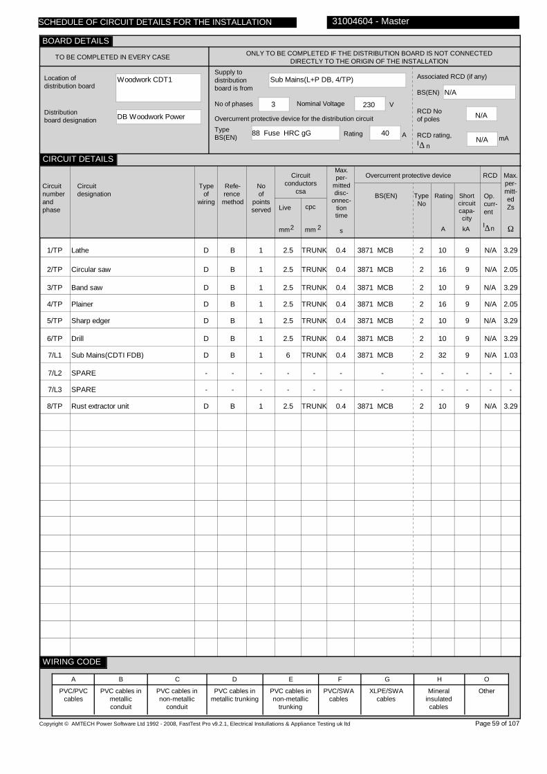
Woodwork CDT1
DB Woodwork Power
Sub Mains(L+P DB, 4/TP)
88 Fuse HRC gG 40
3 230
N/A
N/A
N/A
1/TP
2/TP
3/TP
4/TP
5/TP
6/TP
7/L1
7/L2
7/L3
8/TP
Lathe
Circular saw
Band saw
Plainer
Sharp edger
Drill
Sub Mains(CDTI FDB)
SPARE
SPARE
Rust extractor unit
D
D
D
D
D
D
D
-
-
D
B
B
B
B
B
B
B
-
-
B
1
1
1
1
1
1
1
-
-
1
2.5
2.5
2.5
2.5
2.5
2.5
6
-
-
2.5
TRUNK
TRUNK
TRUNK
TRUNK
TRUNK
TRUNK
TRUNK
-
-
TRUNK
0.4
0.4
0.4
0.4
0.4
0.4
0.4
-
-
0.4
3871 MCB
3871 MCB
3871 MCB
3871 MCB
3871 MCB
3871 MCB
3871 MCB
-
-
3871 MCB
2
2
2
2
2
2
2
-
-
2
10
16
10
16
10
10
32
-
-
10
9
9
9
9
9
9
9
-
-
9
N/A
N/A
N/A
N/A
N/A
N/A
N/A
-
-
N/A
3.29
2.05
3.29
2.05
3.29
3.29
1.03
-
-
3.29
Copyright © AMTECH Power Software Ltd 1992 - 2008, FastTest Pro v9.2.1, Electrical Instullations & Appliance Testing uk ltd
TO BE COMPLETED IN EVERY CASE ONLY TO BE COMPLETED IF THE DISTRIBUTION BOARD IS NOT CONNECTED DIRECTLY TO THE ORIGIN OF THE INSTALLATION
Location of distribution board
Distribution board designation
Supply to distributionboard is from
Overcurrent protective device for the distribution circuitTypeBS(EN) Rating A
No of phases Nominal Voltage V
Associated RCD (if any)
BS(EN)
RCD No of poles
RCD rating,I
mA∆ n
Circuitnumberandphase
Circuitdesignation
Typeof
wiring
Refe-rence method
Noof
pointsserved
Circuitconductors
csa
Live cpc
mm mm2 2
Max.per-
mitteddisc-
onnec-tiontime
s
Overcurrent protective device
BS(EN) Type No
Rating Shortcircuitcapa-city
RCD
Op.curr-ent
I∆n
Max.per-mitt-edZs
Ω
PVC/PVCcables
PVC cables in metallic conduit
PVC cables in non-metallic
conduit
PVC cables in metallic trunking
PVC cables in non-metallic
trunking
PVC/SWAcables
XLPE/SWAcables
Mineralinsulatedcables
Other
31004604 - Master
A B C D E F G H O
Page 59 of 107
SCHEDULE OF CIRCUIT DETAILS FOR THE INSTALLATION
CIRCUIT DETAILS
BOARD DETAILS
WIRING CODE
kAA

0.22
2.14
N/A
N/A
07270722
07270722
07270722
07270722
N/A
1/TP
2/TP
3/TP
4/TP
5/TP
6/TP
7/L1
7/L2
7/L3
8/TP
N/A
N/A
N/A
N/A
N/A
N/A
N/A
-
-
N/A
N/A
N/A
N/A
N/A
N/A
N/A
N/A
-
-
N/A
N/A
N/A
N/A
N/A
N/A
N/A
N/A
-
-
N/A
0.22
0.10
0.15
0.01
0.20
0.20
N/A
-
-
N/A
N/A
N/A
N/A
N/A
N/A
N/A
0.01
-
-
0.04
>10
>10
>10
>10
>10
>10
N/A
-
-
>10
>10
>10
>10
>10
>10
>10
>10
-
-
>10
>10
>10
>10
>10
>10
>10
>10
-
-
>10
>10
>10
>10
>10
>10
>10
>10
-
-
>10
ü
ü
ü
ü
ü
ü
ü
ü
0.45
0.33
0.47
0.23
0.48
0.48
0.20
-
-
0.30
N/A N/A
N/A N/A
N/A N/A
N/A N/A
N/A N/A
N/A N/A
N/A N/A
- -
- -
N/A N/A
Electrical Inspection Engineer
D. Nichols
Copyright © AMTECH Power Software Ltd 1992 - 2008, FastTest Pro v9.2.1, Electrical Instullations & Appliance Testing uk ltd
ONLY TO BE COMPLETED IF THE DISTRIBUTION BOARDIS NOT CONNECTED DIRECTLY TO THE ORIGIN OF THE
INSTALLATION
Zs
Ipf kA
Ω Operating times ofassociatedRCD (if any)
5I
(if applicable)
At I ∆ n ms
ms
N/A
TEST INSTRUMENTS (SERIAL NUMBERS) USED
Earth faultloopimpedance
Insulation resistance
Continuity
RCD
Other
Other
Circuitnumberandphase
Circuit impedances
Ω
Ring final circuits only(measured end to end)
r
(Line)
r
(Neutral)
r
(cpc)
1 2n
All circuits(At least one
columnto be completed)
R + R1 2 R 2
Insulation resistance
Line/Line
Line/Neutral
Line/Earth
Earth/Neutral
Polarity
Ω Ω Ω ΩMMMM
RCD operating times
Maximummeasuredearth fault
loop impedance
Ω msms
At
I ∆ n
Signature
Name
Position
Date of testing
31004604 - Master
Page 60 of 107
n∆
At
5I∆ n
29/07/2010
SCHEDULE OF CIRCUIT TESTS FOR THE INSTALLATION
CIRCUIT TESTS
TESTED BY
BOARD TESTS
Confirmation of Supply polarity ü

CDTI
CDTI FDB
Sub Mains(DB Woodwork Power, 7/L1)
3871 MCB 2 32
1 230
4293 RCD
2
30
1/L1
CDTI sockets
B
B
4
2.5
4
0.4
61009
C
32
10
30
0.72
Copyright © AMTECH Power Software Ltd 1992 - 2008, FastTest Pro v9.2.1, Electrical Instullations & Appliance Testing uk ltd
TO BE COMPLETED IN EVERY CASE ONLY TO BE COMPLETED IF THE DISTRIBUTION BOARD IS NOT CONNECTED DIRECTLY TO THE ORIGIN OF THE INSTALLATION
Location of distribution board
Distribution board designation
Supply to distributionboard is from
Overcurrent protective device for the distribution circuitTypeBS(EN) Rating A
No of phases Nominal Voltage V
Associated RCD (if any)
BS(EN)
RCD No of poles
RCD rating,I
mA∆ n
Circuitnumberandphase
Circuitdesignation
Typeof
wiring
Refe-rence method
Noof
pointsserved
Circuitconductors
csa
Live cpc
mm mm2 2
Max.per-
mitteddisc-
onnec-tiontime
s
Overcurrent protective device
BS(EN) Type No
Rating Shortcircuitcapa-city
RCD
Op.curr-ent
I∆n
Max.per-mitt-edZs
Ω
PVC/PVCcables
PVC cables in metallic conduit
PVC cables in non-metallic
conduit
PVC cables in metallic trunking
PVC cables in non-metallic
trunking
PVC/SWAcables
XLPE/SWAcables
Mineralinsulatedcables
Other
31004604 - Master
A B C D E F G H O
Page 61 of 107
SCHEDULE OF CIRCUIT DETAILS FOR THE INSTALLATION
CIRCUIT DETAILS
BOARD DETAILS
WIRING CODE
kAA
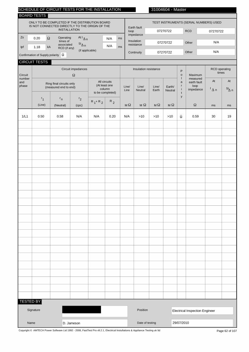
0.20
1.18
N/A
N/A
07270722
07270722
07270722
07270722
N/A
1/L1
0.50
0.58
N/A
N/A
0.20
N/A
>10
>10
>10
ü
0.59
30 19
Electrical Inspection Engineer
D. Jameson
Copyright © AMTECH Power Software Ltd 1992 - 2008, FastTest Pro v9.2.1, Electrical Instullations & Appliance Testing uk ltd
ONLY TO BE COMPLETED IF THE DISTRIBUTION BOARDIS NOT CONNECTED DIRECTLY TO THE ORIGIN OF THE
INSTALLATION
Zs
Ipf kA
Ω Operating times ofassociatedRCD (if any)
5I
(if applicable)
At I ∆ n ms
ms
N/A
TEST INSTRUMENTS (SERIAL NUMBERS) USED
Earth faultloopimpedance
Insulation resistance
Continuity
RCD
Other
Other
Circuitnumberandphase
Circuit impedances
Ω
Ring final circuits only(measured end to end)
r
(Line)
r
(Neutral)
r
(cpc)
1 2n
All circuits(At least one
columnto be completed)
R + R1 2 R 2
Insulation resistance
Line/Line
Line/Neutral
Line/Earth
Earth/Neutral
Polarity
Ω Ω Ω ΩMMMM
RCD operating times
Maximummeasuredearth fault
loop impedance
Ω msms
At
I ∆ n
Signature
Name
Position
Date of testing
31004604 - Master
Page 62 of 107
n∆
At
5I∆ n
29/07/2010
SCHEDULE OF CIRCUIT TESTS FOR THE INSTALLATION
CIRCUIT TESTS
TESTED BY
BOARD TESTS
Confirmation of Supply polarity ü

Kitchen store
DB New Kitchen
Sub Mains(Sub Mains, 1/TP)
88 Fuse HRC gG 100
3 230
N/A
N/A
N/A
1/TP
2/L1
2/L2
2/L3
3/L1
3/L2
3/L3
4/L1
4/L2
4/L3
5/L1
5/L2
5/L3
6/TP
7/TP
8/TP
Cooker extractor
Prep side socket
Left side counter
Hot cupboard
Dishwasher
Oven 1
Fridge
Freezer
SPARE
Fly killer
Lights
Mobile hot cupboard skt
SPARE
SPARE
SPARE
SPARE
E
E
E
E
E
E
E
E
-
E
E
E
-
-
-
-
B
B
B
B
B
B
B
B
-
B
B
B
-
-
-
-
1
1
1
1
1
1
1
1
-
1
6
1
-
-
-
-
10
2.5
2.5
2.5
4
2.5
2.5
2.5
-
2.5
1.5
2.5
-
-
-
-
10
2.5
2.5
2.5
4
2.5
2.5
2.5
-
1.5
2.5
2.5
-
-
-
-
0.4
0.4
0.4
0.4
0.4
0.4
0.4
0.4
-
0.4
0.4
0.4
-
-
-
-
60898 MCB
60898 MCB
60898 MCB
60898 MCB
60898 MCB
60898 MCB
60898 MCB
60898 MCB
-
60898 MCB
60898 MCB
60898 MCB
-
-
-
-
C
B
B
B
B
B
B
B
-
B
B
B
-
-
-
-
32
16
16
16
20
6
16
16
-
16
6
20
-
-
-
-
10
10
10
10
10
10
10
10
-
10
10
10
-
-
-
-
N/A
N/A
N/A
N/A
N/A
N/A
N/A
N/A
-
N/A
N/A
N/A
-
-
-
-
0.72
2.88
2.88
2.88
2.30
7.67
2.88
2.88
-
2.88
7.67
2.30
-
-
-
-
Copyright © AMTECH Power Software Ltd 1992 - 2008, FastTest Pro v9.2.1, Electrical Instullations & Appliance Testing uk ltd
TO BE COMPLETED IN EVERY CASE ONLY TO BE COMPLETED IF THE DISTRIBUTION BOARD IS NOT CONNECTED DIRECTLY TO THE ORIGIN OF THE INSTALLATION
Location of distribution board
Distribution board designation
Supply to distributionboard is from
Overcurrent protective device for the distribution circuitTypeBS(EN) Rating A
No of phases Nominal Voltage V
Associated RCD (if any)
BS(EN)
RCD No of poles
RCD rating,I
mA∆ n
Circuitnumberandphase
Circuitdesignation
Typeof
wiring
Refe-rence method
Noof
pointsserved
Circuitconductors
csa
Live cpc
mm mm2 2
Max.per-
mitteddisc-
onnec-tiontime
s
Overcurrent protective device
BS(EN) Type No
Rating Shortcircuitcapa-city
RCD
Op.curr-ent
I∆n
Max.per-mitt-edZs
Ω
PVC/PVCcables
PVC cables in metallic conduit
PVC cables in non-metallic
conduit
PVC cables in metallic trunking
PVC cables in non-metallic
trunking
PVC/SWAcables
XLPE/SWAcables
Mineralinsulatedcables
Other
31004604 - Master
A B C D E F G H O
Page 63 of 107
SCHEDULE OF CIRCUIT DETAILS FOR THE INSTALLATION
CIRCUIT DETAILS
BOARD DETAILS
WIRING CODE
kAA

0.11
4.14
N/A
N/A
07270722
07270722
07270722
07270722
N/A
1/TP
2/L1
2/L2
2/L3
3/L1
3/L2
3/L3
4/L1
4/L2
4/L3
5/L1
5/L2
5/L3
6/TP
7/TP
8/TP
N/A
N/A
N/A
N/A
N/A
N/A
N/A
N/A
-
N/A
N/A
N/A
-
-
-
-
N/A
N/A
N/A
N/A
N/A
N/A
N/A
N/A
-
N/A
N/A
N/A
-
-
-
-
N/A
N/A
N/A
N/A
N/A
N/A
N/A
N/A
-
N/A
N/A
N/A
-
-
-
-
N/A
0.23
0.27
0.44
0.15
N/A
0.36
0.40
-
N/A
N/A
0.40
-
-
-
-
0.15
N/A
N/A
N/A
N/A
0.40
N/A
N/A
-
0.30
0.46
N/A
-
-
-
-
>10
N/A
N/A
N/A
N/A
N/A
N/A
N/A
-
N/A
N/A
N/A
-
-
-
-
>10
>10
>10
>10
>10
>10
>10
>10
-
>10
LIM
>10
-
-
-
-
>10
>10
>10
>10
>10
>10
>10
>10
-
>10
>10
>10
-
-
-
-
>10
>10
>10
>10
>10
>10
>10
>10
-
>10
>10
>10
-
-
-
-
ü
ü
ü
ü
ü
ü
ü
ü
ü
ü
ü
0.22
0.32
0.37
0.58
0.26
0.42
0.50
0.55
-
0.42
0.40
0.57
-
-
-
-
N/A N/A
N/A N/A
N/A N/A
N/A N/A
N/A N/A
N/A N/A
N/A N/A
N/A N/A
- -
N/A N/A
N/A N/A
N/A N/A
- -
- -
- -
- -
Electrical Inspection Engineer
D. Jameson
Copyright © AMTECH Power Software Ltd 1992 - 2008, FastTest Pro v9.2.1, Electrical Instullations & Appliance Testing uk ltd
ONLY TO BE COMPLETED IF THE DISTRIBUTION BOARDIS NOT CONNECTED DIRECTLY TO THE ORIGIN OF THE
INSTALLATION
Zs
Ipf kA
Ω Operating times ofassociatedRCD (if any)
5I
(if applicable)
At I ∆ n ms
ms
N/A
TEST INSTRUMENTS (SERIAL NUMBERS) USED
Earth faultloopimpedance
Insulation resistance
Continuity
RCD
Other
Other
Circuitnumberandphase
Circuit impedances
Ω
Ring final circuits only(measured end to end)
r
(Line)
r
(Neutral)
r
(cpc)
1 2n
All circuits(At least one
columnto be completed)
R + R1 2 R 2
Insulation resistance
Line/Line
Line/Neutral
Line/Earth
Earth/Neutral
Polarity
Ω Ω Ω ΩMMMM
RCD operating times
Maximummeasuredearth fault
loop impedance
Ω msms
At
I ∆ n
Signature
Name
Position
Date of testing
31004604 - Master
Page 64 of 107
n∆
At
5I∆ n
29/07/2010
SCHEDULE OF CIRCUIT TESTS FOR THE INSTALLATION
CIRCUIT TESTS
TESTED BY
BOARD TESTS
Confirmation of Supply polarity ü

Music
Music Main Switch
Sub Mains(Sub Mains, 2/TP)
88 Fuse HRC gG 100
3 400
N/A
N/A
N/A
1/TP
Sub Mains(L+P Music)
D
B
1
50
35
5
88 Fuse HRC
gG
100
80
N/A
0.42
Copyright © AMTECH Power Software Ltd 1992 - 2008, FastTest Pro v9.2.1, Electrical Instullations & Appliance Testing uk ltd
TO BE COMPLETED IN EVERY CASE ONLY TO BE COMPLETED IF THE DISTRIBUTION BOARD IS NOT CONNECTED DIRECTLY TO THE ORIGIN OF THE INSTALLATION
Location of distribution board
Distribution board designation
Supply to distributionboard is from
Overcurrent protective device for the distribution circuitTypeBS(EN) Rating A
No of phases Nominal Voltage V
Associated RCD (if any)
BS(EN)
RCD No of poles
RCD rating,I
mA∆ n
Circuitnumberandphase
Circuitdesignation
Typeof
wiring
Refe-rence method
Noof
pointsserved
Circuitconductors
csa
Live cpc
mm mm2 2
Max.per-
mitteddisc-
onnec-tiontime
s
Overcurrent protective device
BS(EN) Type No
Rating Shortcircuitcapa-city
RCD
Op.curr-ent
I∆n
Max.per-mitt-edZs
Ω
PVC/PVCcables
PVC cables in metallic conduit
PVC cables in non-metallic
conduit
PVC cables in metallic trunking
PVC cables in non-metallic
trunking
PVC/SWAcables
XLPE/SWAcables
Mineralinsulatedcables
Other
31004604 - Master
A B C D E F G H O
Page 65 of 107
SCHEDULE OF CIRCUIT DETAILS FOR THE INSTALLATION
CIRCUIT DETAILS
BOARD DETAILS
WIRING CODE
kAA
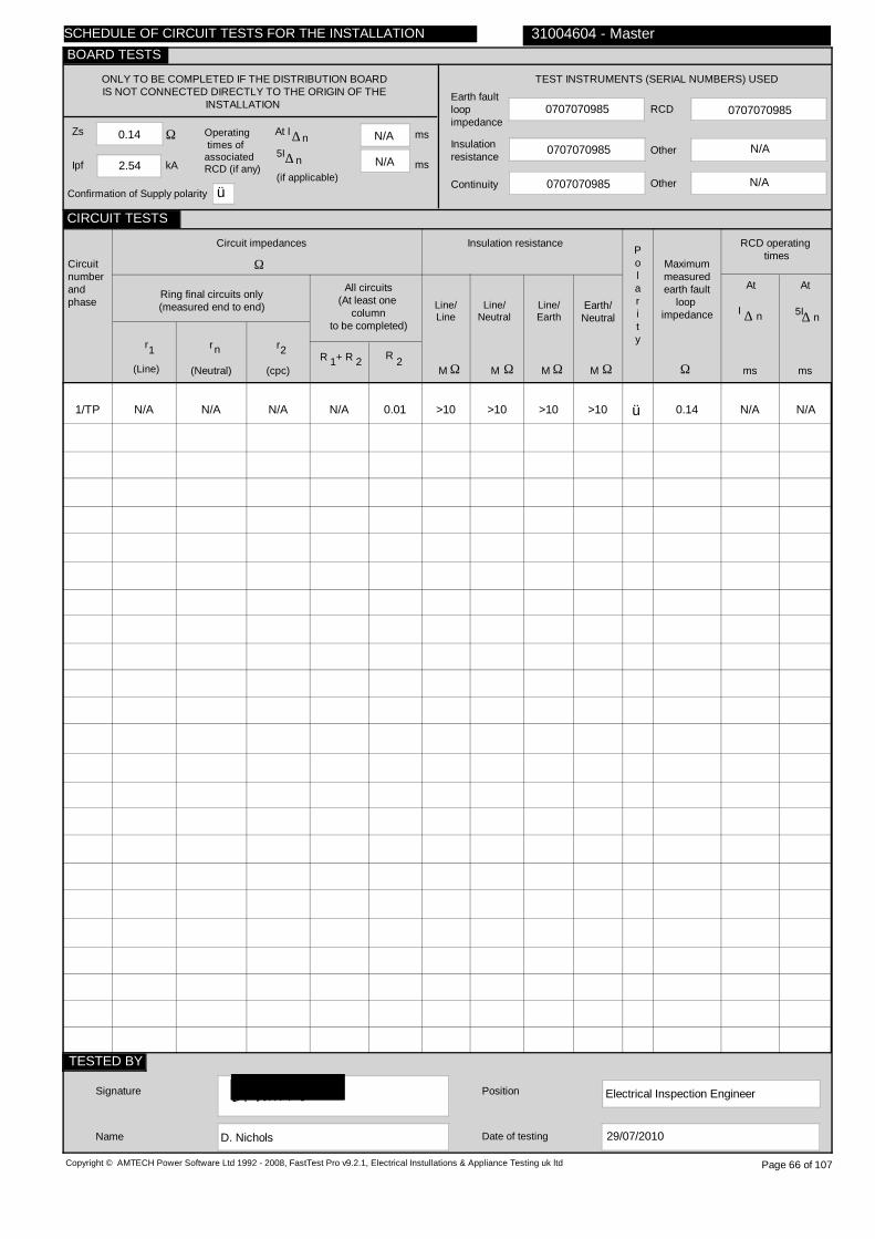
0.14
2.54
N/A
N/A
0707070985
0707070985
0707070985
0707070985
N/A
1/TP
N/A
N/A
N/A
N/A
0.01
>10
>10
>10
>10
ü
0.14
N/A N/A
Electrical Inspection Engineer
D. Nichols
Copyright © AMTECH Power Software Ltd 1992 - 2008, FastTest Pro v9.2.1, Electrical Instullations & Appliance Testing uk ltd
ONLY TO BE COMPLETED IF THE DISTRIBUTION BOARDIS NOT CONNECTED DIRECTLY TO THE ORIGIN OF THE
INSTALLATION
Zs
Ipf kA
Ω Operating times ofassociatedRCD (if any)
5I
(if applicable)
At I ∆ n ms
ms
N/A
TEST INSTRUMENTS (SERIAL NUMBERS) USED
Earth faultloopimpedance
Insulation resistance
Continuity
RCD
Other
Other
Circuitnumberandphase
Circuit impedances
Ω
Ring final circuits only(measured end to end)
r
(Line)
r
(Neutral)
r
(cpc)
1 2n
All circuits(At least one
columnto be completed)
R + R1 2 R 2
Insulation resistance
Line/Line
Line/Neutral
Line/Earth
Earth/Neutral
Polarity
Ω Ω Ω ΩMMMM
RCD operating times
Maximummeasuredearth fault
loop impedance
Ω msms
At
I ∆ n
Signature
Name
Position
Date of testing
31004604 - Master
Page 66 of 107
n∆
At
5I∆ n
29/07/2010
SCHEDULE OF CIRCUIT TESTS FOR THE INSTALLATION
CIRCUIT TESTS
TESTED BY
BOARD TESTS
Confirmation of Supply polarity ü
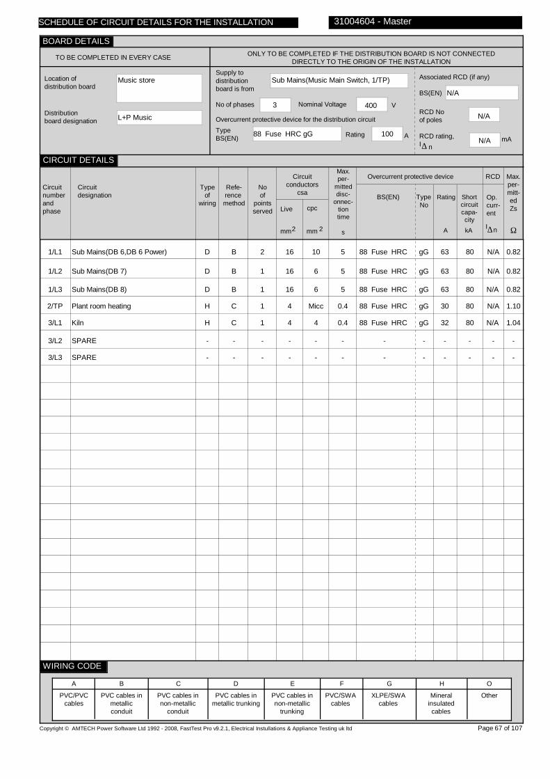
Music store
L+P Music
Sub Mains(Music Main Switch, 1/TP)
88 Fuse HRC gG 100
3 400
N/A
N/A
N/A
1/L1
1/L2
1/L3
2/TP
3/L1
3/L2
3/L3
Sub Mains(DB 6,DB 6 Power)
Sub Mains(DB 7)
Sub Mains(DB 8)
Plant room heating
Kiln
SPARE
SPARE
D
D
D
H
H
-
-
B
B
B
C
C
-
-
2
1
1
1
1
-
-
16
16
16
4
4
-
-
10
6
6
Micc
4
-
-
5
5
5
0.4
0.4
-
-
88 Fuse HRC
88 Fuse HRC
88 Fuse HRC
88 Fuse HRC
88 Fuse HRC
-
-
gG
gG
gG
gG
gG
-
-
63
63
63
30
32
-
-
80
80
80
80
80
-
-
N/A
N/A
N/A
N/A
N/A
-
-
0.82
0.82
0.82
1.10
1.04
-
-
Copyright © AMTECH Power Software Ltd 1992 - 2008, FastTest Pro v9.2.1, Electrical Instullations & Appliance Testing uk ltd
TO BE COMPLETED IN EVERY CASE ONLY TO BE COMPLETED IF THE DISTRIBUTION BOARD IS NOT CONNECTED DIRECTLY TO THE ORIGIN OF THE INSTALLATION
Location of distribution board
Distribution board designation
Supply to distributionboard is from
Overcurrent protective device for the distribution circuitTypeBS(EN) Rating A
No of phases Nominal Voltage V
Associated RCD (if any)
BS(EN)
RCD No of poles
RCD rating,I
mA∆ n
Circuitnumberandphase
Circuitdesignation
Typeof
wiring
Refe-rence method
Noof
pointsserved
Circuitconductors
csa
Live cpc
mm mm2 2
Max.per-
mitteddisc-
onnec-tiontime
s
Overcurrent protective device
BS(EN) Type No
Rating Shortcircuitcapa-city
RCD
Op.curr-ent
I∆n
Max.per-mitt-edZs
Ω
PVC/PVCcables
PVC cables in metallic conduit
PVC cables in non-metallic
conduit
PVC cables in metallic trunking
PVC cables in non-metallic
trunking
PVC/SWAcables
XLPE/SWAcables
Mineralinsulatedcables
Other
31004604 - Master
A B C D E F G H O
Page 67 of 107
SCHEDULE OF CIRCUIT DETAILS FOR THE INSTALLATION
CIRCUIT DETAILS
BOARD DETAILS
WIRING CODE
kAA

0.14
2.56
N/A
N/A
07270722
07270722
07270722
07270722
N/A
1/L1
1/L2
1/L3
2/TP
3/L1
3/L2
3/L3
N/A
N/A
N/A
N/A
N/A
-
-
N/A
N/A
N/A
N/A
N/A
-
-
N/A
N/A
N/A
N/A
N/A
-
-
N/A
N/A
N/A
0.12
N/A
-
-
0.01
0.10
0.10
N/A
0.10
-
-
N/A
N/A
N/A
>10
N/A
-
-
>10
>10
>10
>10
>10
-
-
>10
>10
>10
>10
>10
-
-
>10
>10
>10
>10
>10
-
-
ü
ü
ü
ü
ü
0.14
0.20
0.21
0.28
0.21
-
-
N/A N/A
N/A N/A
N/A N/A
N/A N/A
N/A N/A
- -
- -
Electrical Inspection Engineer
D. Nichols
Copyright © AMTECH Power Software Ltd 1992 - 2008, FastTest Pro v9.2.1, Electrical Instullations & Appliance Testing uk ltd
ONLY TO BE COMPLETED IF THE DISTRIBUTION BOARDIS NOT CONNECTED DIRECTLY TO THE ORIGIN OF THE
INSTALLATION
Zs
Ipf kA
Ω Operating times ofassociatedRCD (if any)
5I
(if applicable)
At I ∆ n ms
ms
N/A
TEST INSTRUMENTS (SERIAL NUMBERS) USED
Earth faultloopimpedance
Insulation resistance
Continuity
RCD
Other
Other
Circuitnumberandphase
Circuit impedances
Ω
Ring final circuits only(measured end to end)
r
(Line)
r
(Neutral)
r
(cpc)
1 2n
All circuits(At least one
columnto be completed)
R + R1 2 R 2
Insulation resistance
Line/Line
Line/Neutral
Line/Earth
Earth/Neutral
Polarity
Ω Ω Ω ΩMMMM
RCD operating times
Maximummeasuredearth fault
loop impedance
Ω msms
At
I ∆ n
Signature
Name
Position
Date of testing
31004604 - Master
Page 68 of 107
n∆
At
5I∆ n
29/07/2010
SCHEDULE OF CIRCUIT TESTS FOR THE INSTALLATION
CIRCUIT TESTS
TESTED BY
BOARD TESTS
Confirmation of Supply polarity ü

Music store
DB 6
Sub Mains(L+P Music, 1/L1)
88 Fuse HRC gG 63
1 230
N/A
N/A
N/A
1/L1
2/L1
3/L1
4/L1
5/L1
6/L1
7/L1
8/L1
9/L1
10/L1
11/L1
12/L1
13/L1
14/L1
15/L1
Room A lights
Room A lights
Store lights
Art room B lights
Art room B & stairs lts
Room T4 lights
Unable to locate
SPARE
Alarm
SPARE
Sub Mains(FDB Art)
Sub Mains(FDB T4)
SPARE
SPARE
SPARE
D
D
D
D
D
D
D
-
D
-
D
H
-
-
-
B
B
B
B
B
B
B
-
B
-
B
C
-
-
-
9
4
2
10
10
12
N/V
-
1
-
1
1
-
-
-
1.5
1.5
1.5
1.5
1.5
1.5
1.5
-
2.5
-
10
6
-
-
-
TRUNK
TRUNK
TRUNK
TRUNK
TRUNK
TRUNK
TRUNK
-
TRUNK
TRUNK
-
6
-
-
-
0.4
0.4
0.4
0.4
0.4
0.4
0.4
-
0.4
-
0.4
0.4
-
-
-
3871 MCB
3871 MCB
3871 MCB
3871 MCB
3871 MCB
3871 MCB
3871 MCB
-
3871 MCB
-
3871 MCB
3871 MCB
-
-
-
2
2
2
2
2
2
2
-
2
-
2
2
-
-
-
10
10
10
10
10
10
10
-
10
-
32
32
-
-
-
9
9
9
9
9
9
9
-
9
-
9
9
-
-
-
N/A
N/A
N/A
N/A
N/A
N/A
N/A
-
N/A
-
N/A
N/A
-
-
-
3.29
3.29
3.29
3.29
3.29
3.29
3.29
-
3.29
-
1.03
1.03
-
-
-
Copyright © AMTECH Power Software Ltd 1992 - 2008, FastTest Pro v9.2.1, Electrical Instullations & Appliance Testing uk ltd
TO BE COMPLETED IN EVERY CASE ONLY TO BE COMPLETED IF THE DISTRIBUTION BOARD IS NOT CONNECTED DIRECTLY TO THE ORIGIN OF THE INSTALLATION
Location of distribution board
Distribution board designation
Supply to distributionboard is from
Overcurrent protective device for the distribution circuitTypeBS(EN) Rating A
No of phases Nominal Voltage V
Associated RCD (if any)
BS(EN)
RCD No of poles
RCD rating,I
mA∆ n
Circuitnumberandphase
Circuitdesignation
Typeof
wiring
Refe-rence method
Noof
pointsserved
Circuitconductors
csa
Live cpc
mm mm2 2
Max.per-
mitteddisc-
onnec-tiontime
s
Overcurrent protective device
BS(EN) Type No
Rating Shortcircuitcapa-city
RCD
Op.curr-ent
I∆n
Max.per-mitt-edZs
Ω
PVC/PVCcables
PVC cables in metallic conduit
PVC cables in non-metallic
conduit
PVC cables in metallic trunking
PVC cables in non-metallic
trunking
PVC/SWAcables
XLPE/SWAcables
Mineralinsulatedcables
Other
31004604 - Master
A B C D E F G H O
Page 69 of 107
SCHEDULE OF CIRCUIT DETAILS FOR THE INSTALLATION
CIRCUIT DETAILS
BOARD DETAILS
WIRING CODE
kAA

0.14
1.81
N/A
N/A
07270722
07270722
07270722
07270722
N/A
1/L1
2/L1
3/L1
4/L1
5/L1
6/L1
7/L1
8/L1
9/L1
10/L1
11/L1
12/L1
13/L1
14/L1
15/L1
N/A
N/A
N/A
N/A
N/A
N/A
UNABLE
-
N/A
-
N/A
N/A
-
-
-
N/A
N/A
N/A
N/A
N/A
N/A
TO
-
N/A
-
N/A
N/A
-
-
-
N/A
N/A
N/A
N/A
N/A
N/A
LOCATE
-
N/A
-
N/A
N/A
-
-
-
N/A
N/A
N/A
N/A
N/A
N/A
LIM
-
LIM
-
0.04
0.07
-
-
-
0.14
0.14
0.02
0.14
0.15
0.16
LIM
-
LIM
-
N/A
N/A
-
-
-
N/A
N/A
N/A
N/A
N/A
N/A
N/A
-
N/A
-
N/A
N/A
-
-
-
LIM
LIM
LIM
LIM
LIM
LIM
LIM
-
LIM
-
>10
>10
-
-
-
>10
>10
>10
>10
>10
>10
LIM
-
LIM
-
>10
>10
-
-
-
>10
>10
>10
>10
>10
>10
LIM
-
LIM
-
>10
>10
-
-
-
ü
ü
ü
ü
ü
ü
ü
ü
0.33
0.34
0.19
0.39
0.44
0.48
LIM
-
LIM
-
0.19
0.23
-
-
-
N/A N/A
N/A N/A
N/A N/A
N/A N/A
N/A N/A
N/A N/A
N/A N/A
- -
N/A N/A
- -
N/A N/A
N/A N/A
- -
- -
- -
Electrical Inspection Engineer
D. Nichols
Copyright © AMTECH Power Software Ltd 1992 - 2008, FastTest Pro v9.2.1, Electrical Instullations & Appliance Testing uk ltd
ONLY TO BE COMPLETED IF THE DISTRIBUTION BOARDIS NOT CONNECTED DIRECTLY TO THE ORIGIN OF THE
INSTALLATION
Zs
Ipf kA
Ω Operating times ofassociatedRCD (if any)
5I
(if applicable)
At I ∆ n ms
ms
N/A
TEST INSTRUMENTS (SERIAL NUMBERS) USED
Earth faultloopimpedance
Insulation resistance
Continuity
RCD
Other
Other
Circuitnumberandphase
Circuit impedances
Ω
Ring final circuits only(measured end to end)
r
(Line)
r
(Neutral)
r
(cpc)
1 2n
All circuits(At least one
columnto be completed)
R + R1 2 R 2
Insulation resistance
Line/Line
Line/Neutral
Line/Earth
Earth/Neutral
Polarity
Ω Ω Ω ΩMMMM
RCD operating times
Maximummeasuredearth fault
loop impedance
Ω msms
At
I ∆ n
Signature
Name
Position
Date of testing
31004604 - Master
Page 70 of 107
n∆
At
5I∆ n
29/07/2010
SCHEDULE OF CIRCUIT TESTS FOR THE INSTALLATION
CIRCUIT TESTS
TESTED BY
BOARD TESTS
Confirmation of Supply polarity ü

Room
FDB T4
Sub Mains(DB 6, 12/L1)
3871 MCB 2 32
1 230
4293 RCD
2
30
1/L1
T4 left & metal sockets
B
B
15
2.5
1.5
0.4
61009
C
32
9
30
0.72
Copyright © AMTECH Power Software Ltd 1992 - 2008, FastTest Pro v9.2.1, Electrical Instullations & Appliance Testing uk ltd
TO BE COMPLETED IN EVERY CASE ONLY TO BE COMPLETED IF THE DISTRIBUTION BOARD IS NOT CONNECTED DIRECTLY TO THE ORIGIN OF THE INSTALLATION
Location of distribution board
Distribution board designation
Supply to distributionboard is from
Overcurrent protective device for the distribution circuitTypeBS(EN) Rating A
No of phases Nominal Voltage V
Associated RCD (if any)
BS(EN)
RCD No of poles
RCD rating,I
mA∆ n
Circuitnumberandphase
Circuitdesignation
Typeof
wiring
Refe-rence method
Noof
pointsserved
Circuitconductors
csa
Live cpc
mm mm2 2
Max.per-
mitteddisc-
onnec-tiontime
s
Overcurrent protective device
BS(EN) Type No
Rating Shortcircuitcapa-city
RCD
Op.curr-ent
I∆n
Max.per-mitt-edZs
Ω
PVC/PVCcables
PVC cables in metallic conduit
PVC cables in non-metallic
conduit
PVC cables in metallic trunking
PVC cables in non-metallic
trunking
PVC/SWAcables
XLPE/SWAcables
Mineralinsulatedcables
Other
31004604 - Master
A B C D E F G H O
Page 71 of 107
SCHEDULE OF CIRCUIT DETAILS FOR THE INSTALLATION
CIRCUIT DETAILS
BOARD DETAILS
WIRING CODE
kAA

0.23
1.07
N/A
N/A
07270722
07270722
07270722
07270722
N/A
1/L1
0.66
0.68
0.73
0.36
N/A
N/A
>10
>10
>10
ü
0.71
29 8
Electrical Inspection Engineer
D. Jameson
Copyright © AMTECH Power Software Ltd 1992 - 2008, FastTest Pro v9.2.1, Electrical Instullations & Appliance Testing uk ltd
ONLY TO BE COMPLETED IF THE DISTRIBUTION BOARDIS NOT CONNECTED DIRECTLY TO THE ORIGIN OF THE
INSTALLATION
Zs
Ipf kA
Ω Operating times ofassociatedRCD (if any)
5I
(if applicable)
At I ∆ n ms
ms
N/A
TEST INSTRUMENTS (SERIAL NUMBERS) USED
Earth faultloopimpedance
Insulation resistance
Continuity
RCD
Other
Other
Circuitnumberandphase
Circuit impedances
Ω
Ring final circuits only(measured end to end)
r
(Line)
r
(Neutral)
r
(cpc)
1 2n
All circuits(At least one
columnto be completed)
R + R1 2 R 2
Insulation resistance
Line/Line
Line/Neutral
Line/Earth
Earth/Neutral
Polarity
Ω Ω Ω ΩMMMM
RCD operating times
Maximummeasuredearth fault
loop impedance
Ω msms
At
I ∆ n
Signature
Name
Position
Date of testing
31004604 - Master
Page 72 of 107
n∆
At
5I∆ n
29/07/2010
SCHEDULE OF CIRCUIT TESTS FOR THE INSTALLATION
CIRCUIT TESTS
TESTED BY
BOARD TESTS
Confirmation of Supply polarity ü

Art
FDB Art
Sub Mains(DB 6, 11/L1)
3871 MCB 2 32
1 230
4293 RCD
2
30
1/L1
Art room sockets
B
B
8
2.5
2.5
0.4
61009
C
32
6
30
0.72
Copyright © AMTECH Power Software Ltd 1992 - 2008, FastTest Pro v9.2.1, Electrical Instullations & Appliance Testing uk ltd
TO BE COMPLETED IN EVERY CASE ONLY TO BE COMPLETED IF THE DISTRIBUTION BOARD IS NOT CONNECTED DIRECTLY TO THE ORIGIN OF THE INSTALLATION
Location of distribution board
Distribution board designation
Supply to distributionboard is from
Overcurrent protective device for the distribution circuitTypeBS(EN) Rating A
No of phases Nominal Voltage V
Associated RCD (if any)
BS(EN)
RCD No of poles
RCD rating,I
mA∆ n
Circuitnumberandphase
Circuitdesignation
Typeof
wiring
Refe-rence method
Noof
pointsserved
Circuitconductors
csa
Live cpc
mm mm2 2
Max.per-
mitteddisc-
onnec-tiontime
s
Overcurrent protective device
BS(EN) Type No
Rating Shortcircuitcapa-city
RCD
Op.curr-ent
I∆n
Max.per-mitt-edZs
Ω
PVC/PVCcables
PVC cables in metallic conduit
PVC cables in non-metallic
conduit
PVC cables in metallic trunking
PVC cables in non-metallic
trunking
PVC/SWAcables
XLPE/SWAcables
Mineralinsulatedcables
Other
31004604 - Master
A B C D E F G H O
Page 73 of 107
SCHEDULE OF CIRCUIT DETAILS FOR THE INSTALLATION
CIRCUIT DETAILS
BOARD DETAILS
WIRING CODE
kAA

0.19
1.41
46
17
07270722
07270722
07270722
07270722
N/A
1/L1
0.47
0.45
0.14
0.08
N/A
N/A
>10
>10
>10
ü
0.97
46 17
Electrical Inspection Engineer
D. Nichols
Copyright © AMTECH Power Software Ltd 1992 - 2008, FastTest Pro v9.2.1, Electrical Instullations & Appliance Testing uk ltd
ONLY TO BE COMPLETED IF THE DISTRIBUTION BOARDIS NOT CONNECTED DIRECTLY TO THE ORIGIN OF THE
INSTALLATION
Zs
Ipf kA
Ω Operating times ofassociatedRCD (if any)
5I
(if applicable)
At I ∆ n ms
ms
N/A
TEST INSTRUMENTS (SERIAL NUMBERS) USED
Earth faultloopimpedance
Insulation resistance
Continuity
RCD
Other
Other
Circuitnumberandphase
Circuit impedances
Ω
Ring final circuits only(measured end to end)
r
(Line)
r
(Neutral)
r
(cpc)
1 2n
All circuits(At least one
columnto be completed)
R + R1 2 R 2
Insulation resistance
Line/Line
Line/Neutral
Line/Earth
Earth/Neutral
Polarity
Ω Ω Ω ΩMMMM
RCD operating times
Maximummeasuredearth fault
loop impedance
Ω msms
At
I ∆ n
Signature
Name
Position
Date of testing
31004604 - Master
Page 74 of 107
n∆
At
5I∆ n
29/07/2010
SCHEDULE OF CIRCUIT TESTS FOR THE INSTALLATION
CIRCUIT TESTS
TESTED BY
BOARD TESTS
Confirmation of Supply polarity ü

Music store
DB 6 Power
Sub Mains(L+P Music, 1/L1)
88 Fuse HRC gG 63
1 230
N/A
N/A
N/A
1/L1
2/L1
3/L1
4/L1
5/L1
6/L1
7/L1
Room A sockets
Unable to locate
Practice & store rm skts
Room A far sockets
Room A near sockets
Room T4 right sockets
Room T4 left sockets
D
D
D
D
H
D
D
B
B
B
B
C
B
B
8
N/V
12
9
5
14
14
2.5
2.5
2.5
2.5
1.5
2.5
2.5
1.5
1.5
1.5
1.5
Micc
1.5
1.5
0.4
0.4
0.4
0.4
0.4
0.4
0.4
61009
61009
61009
61009
61009
61009
61009
C
C
C
B
C
C
C
32
32
32
32
16
32
32
10
10
10
10
10
10
10
30
30
30
30
30
30
30
0.72
0.72
0.72
1.44
1.44
0.72
0.72
Copyright © AMTECH Power Software Ltd 1992 - 2008, FastTest Pro v9.2.1, Electrical Instullations & Appliance Testing uk ltd
TO BE COMPLETED IN EVERY CASE ONLY TO BE COMPLETED IF THE DISTRIBUTION BOARD IS NOT CONNECTED DIRECTLY TO THE ORIGIN OF THE INSTALLATION
Location of distribution board
Distribution board designation
Supply to distributionboard is from
Overcurrent protective device for the distribution circuitTypeBS(EN) Rating A
No of phases Nominal Voltage V
Associated RCD (if any)
BS(EN)
RCD No of poles
RCD rating,I
mA∆ n
Circuitnumberandphase
Circuitdesignation
Typeof
wiring
Refe-rence method
Noof
pointsserved
Circuitconductors
csa
Live cpc
mm mm2 2
Max.per-
mitteddisc-
onnec-tiontime
s
Overcurrent protective device
BS(EN) Type No
Rating Shortcircuitcapa-city
RCD
Op.curr-ent
I∆n
Max.per-mitt-edZs
Ω
PVC/PVCcables
PVC cables in metallic conduit
PVC cables in non-metallic
conduit
PVC cables in metallic trunking
PVC cables in non-metallic
trunking
PVC/SWAcables
XLPE/SWAcables
Mineralinsulatedcables
Other
31004604 - Master
A B C D E F G H O
Page 75 of 107
SCHEDULE OF CIRCUIT DETAILS FOR THE INSTALLATION
CIRCUIT DETAILS
BOARD DETAILS
WIRING CODE
kAA

0.14
1.81
N/A
N/A
07270722
07270722
07270722
07270722
N/A
1/L1
2/L1
3/L1
4/L1
5/L1
6/L1
7/L1
0.73
UNABLE
0.57
0.60
N/A
0.50
0.41
0.74
TO
0.58
0.62
N/A
0.50
0.42
0.23
LOCATE
0.02
0.41
N/A
0.81
0.69
0.26
LIM
0.02
0.24
0.40
0.33
0.26
N/A
LIM
N/A
N/A
N/A
N/A
N/A
N/A
N/A
N/A
N/A
N/A
N/A
N/A
>10
LIM
>10
>10
>10
>10
>10
>10
LIM
>10
>10
>10
>10
>10
>10
>10
LIM
>10
>10
>10
>10
ü
ü
ü
ü
ü
ü
0.53
LIM
0.81
0.79
0.65
0.89
0.68
15 9
LIM LIM
47 21
47 21
37 16
15 15
15 14
Electrical Inspection Engineer
D. Jameson
Copyright © AMTECH Power Software Ltd 1992 - 2008, FastTest Pro v9.2.1, Electrical Instullations & Appliance Testing uk ltd
ONLY TO BE COMPLETED IF THE DISTRIBUTION BOARDIS NOT CONNECTED DIRECTLY TO THE ORIGIN OF THE
INSTALLATION
Zs
Ipf kA
Ω Operating times ofassociatedRCD (if any)
5I
(if applicable)
At I ∆ n ms
ms
N/A
TEST INSTRUMENTS (SERIAL NUMBERS) USED
Earth faultloopimpedance
Insulation resistance
Continuity
RCD
Other
Other
Circuitnumberandphase
Circuit impedances
Ω
Ring final circuits only(measured end to end)
r
(Line)
r
(Neutral)
r
(cpc)
1 2n
All circuits(At least one
columnto be completed)
R + R1 2 R 2
Insulation resistance
Line/Line
Line/Neutral
Line/Earth
Earth/Neutral
Polarity
Ω Ω Ω ΩMMMM
RCD operating times
Maximummeasuredearth fault
loop impedance
Ω msms
At
I ∆ n
Signature
Name
Position
Date of testing
31004604 - Master
Page 76 of 107
n∆
At
5I∆ n
29/07/2010
SCHEDULE OF CIRCUIT TESTS FOR THE INSTALLATION
CIRCUIT TESTS
TESTED BY
BOARD TESTS
Confirmation of Supply polarity ü
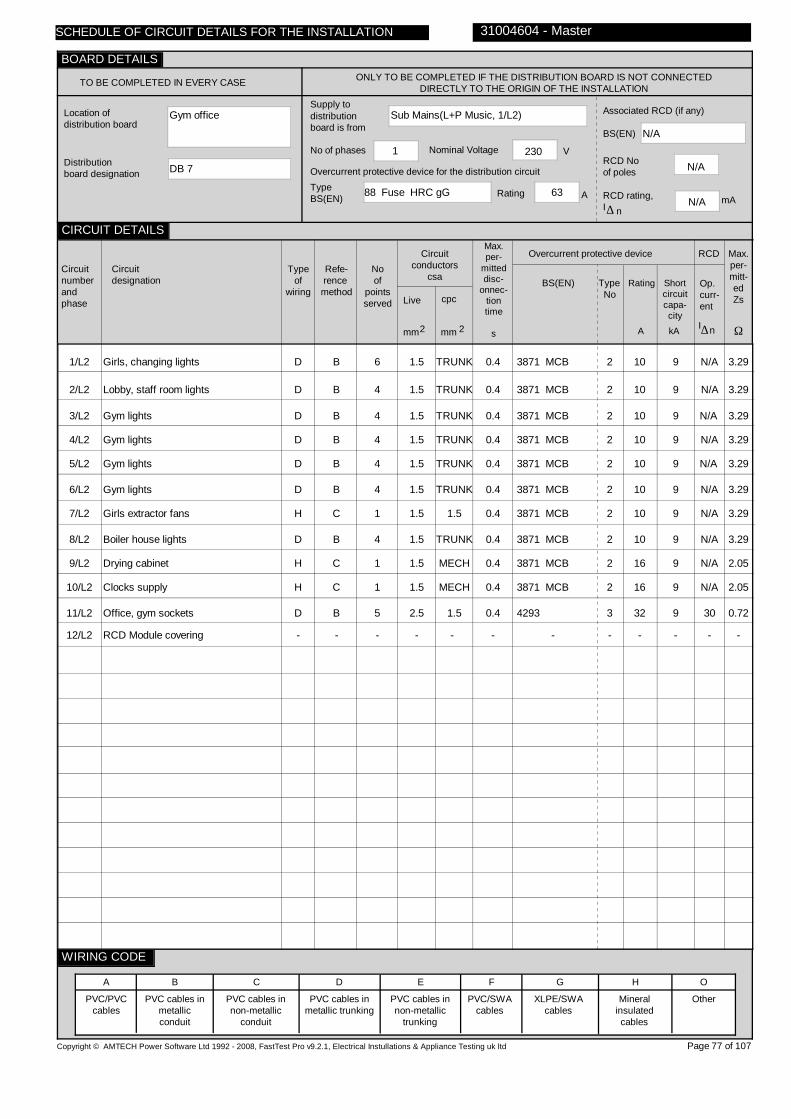
Gym office
DB 7
Sub Mains(L+P Music, 1/L2)
88 Fuse HRC gG 63
1 230
N/A
N/A
N/A
1/L2
2/L2
3/L2
4/L2
5/L2
6/L2
7/L2
8/L2
9/L2
10/L2
11/L2
12/L2
Girls, changing lights
Lobby, staff room lights
Gym lights
Gym lights
Gym lights
Gym lights
Girls extractor fans
Boiler house lights
Drying cabinet
Clocks supply
Office, gym sockets
RCD Module covering
D
D
D
D
D
D
H
D
H
H
D
-
B
B
B
B
B
B
C
B
C
C
B
-
6
4
4
4
4
4
1
4
1
1
5
-
1.5
1.5
1.5
1.5
1.5
1.5
1.5
1.5
1.5
1.5
2.5
-
TRUNK
TRUNK
TRUNK
TRUNK
TRUNK
TRUNK
1.5
TRUNK
MECH
1.5
MECH
-
0.4
0.4
0.4
0.4
0.4
0.4
0.4
0.4
0.4
0.4
0.4
-
3871 MCB
3871 MCB
3871 MCB
3871 MCB
3871 MCB
3871 MCB
3871 MCB
3871 MCB
3871 MCB
3871 MCB
4293
-
2
2
2
2
2
2
2
2
2
2
3
-
10
10
10
10
10
10
10
10
16
16
32
-
9
9
9
9
9
9
9
9
9
9
9
-
N/A
N/A
N/A
N/A
N/A
N/A
N/A
N/A
N/A
N/A
30
-
3.29
3.29
3.29
3.29
3.29
3.29
3.29
3.29
2.05
2.05
0.72
-
Copyright © AMTECH Power Software Ltd 1992 - 2008, FastTest Pro v9.2.1, Electrical Instullations & Appliance Testing uk ltd
TO BE COMPLETED IN EVERY CASE ONLY TO BE COMPLETED IF THE DISTRIBUTION BOARD IS NOT CONNECTED DIRECTLY TO THE ORIGIN OF THE INSTALLATION
Location of distribution board
Distribution board designation
Supply to distributionboard is from
Overcurrent protective device for the distribution circuitTypeBS(EN) Rating A
No of phases Nominal Voltage V
Associated RCD (if any)
BS(EN)
RCD No of poles
RCD rating,I
mA∆ n
Circuitnumberandphase
Circuitdesignation
Typeof
wiring
Refe-rence method
Noof
pointsserved
Circuitconductors
csa
Live cpc
mm mm2 2
Max.per-
mitteddisc-
onnec-tiontime
s
Overcurrent protective device
BS(EN) Type No
Rating Shortcircuitcapa-city
RCD
Op.curr-ent
I∆n
Max.per-mitt-edZs
Ω
PVC/PVCcables
PVC cables in metallic conduit
PVC cables in non-metallic
conduit
PVC cables in metallic trunking
PVC cables in non-metallic
trunking
PVC/SWAcables
XLPE/SWAcables
Mineralinsulatedcables
Other
31004604 - Master
A B C D E F G H O
Page 77 of 107
SCHEDULE OF CIRCUIT DETAILS FOR THE INSTALLATION
CIRCUIT DETAILS
BOARD DETAILS
WIRING CODE
kAA

0.20
1.07
N/A
N/A
07270722
07270722
07270722
07270722
N/A
1/L2
2/L2
3/L2
4/L2
5/L2
6/L2
7/L2
8/L2
9/L2
10/L2
11/L2
12/L2
N/A
N/A
N/A
N/A
N/A
N/A
N/A
N/A
N/A
N/A
0.22
-
N/A
N/A
N/A
N/A
N/A
N/A
N/A
N/A
N/A
N/A
0.26
-
N/A
N/A
N/A
N/A
N/A
N/A
N/A
N/A
N/A
N/A
0.49
-
0.17
N/A
N/A
N/A
N/A
N/A
0.15
0.40
0.21
LIM
0.16
-
N/A
0.23
0.10
0.79
0.32
0.13
N/A
N/A
N/A
LIM
N/A
-
N/A
N/A
N/A
N/A
N/A
N/A
N/A
N/A
N/A
N/A
N/A
-
LIM
LIM
LIM
LIM
LIM
LIM
>10
LIM
>10
LIM
>10
-
>10
>10
>10
>10
>10
>10
>10
>10
>10
LIM
>10
-
>10
>10
>10
>10
>10
>10
>10
>10
>10
LIM
>10
-
ü
ü
ü
ü
ü
ü
ü
ü
ü
ü
0.40
0.43
0.28
0.83
0.44
0.30
0.37
0.62
0.44
LIM
0.79
-
N/A N/A
N/A N/A
N/A N/A
N/A N/A
N/A N/A
N/A N/A
N/A N/A
N/A N/A
N/A N/A
N/A N/A
9 4
- -
Electrical Inspection Engineer
D. Jameson
Copyright © AMTECH Power Software Ltd 1992 - 2008, FastTest Pro v9.2.1, Electrical Instullations & Appliance Testing uk ltd
ONLY TO BE COMPLETED IF THE DISTRIBUTION BOARDIS NOT CONNECTED DIRECTLY TO THE ORIGIN OF THE
INSTALLATION
Zs
Ipf kA
Ω Operating times ofassociatedRCD (if any)
5I
(if applicable)
At I ∆ n ms
ms
N/A
TEST INSTRUMENTS (SERIAL NUMBERS) USED
Earth faultloopimpedance
Insulation resistance
Continuity
RCD
Other
Other
Circuitnumberandphase
Circuit impedances
Ω
Ring final circuits only(measured end to end)
r
(Line)
r
(Neutral)
r
(cpc)
1 2n
All circuits(At least one
columnto be completed)
R + R1 2 R 2
Insulation resistance
Line/Line
Line/Neutral
Line/Earth
Earth/Neutral
Polarity
Ω Ω Ω ΩMMMM
RCD operating times
Maximummeasuredearth fault
loop impedance
Ω msms
At
I ∆ n
Signature
Name
Position
Date of testing
31004604 - Master
Page 78 of 107
n∆
At
5I∆ n
29/07/2010
SCHEDULE OF CIRCUIT TESTS FOR THE INSTALLATION
CIRCUIT TESTS
TESTED BY
BOARD TESTS
Confirmation of Supply polarity ü
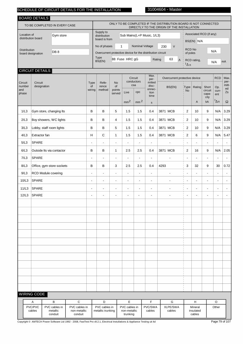
Gym store
DB 8
Sub Mains(L+P Music, 1/L3)
88 Fuse HRC gG 63
1 230
N/A
N/A
N/A
1/L3
2/L3
3/L3
4/L3
5/L3
6/L3
7/L3
8/L3
9/L3
10/L3
11/L3
12/L3
Gym store, changing lts
Boy showers, WC lights
Lobby, staff room lights
Extractor fan
SPARE
Outside lts via contactor
SPARE
Office, gym store sockets
RCD Module covering
SPARE
SPARE
SPARE
B
B
B
H
-
B
-
B
-
-
-
-
B
B
B
C
-
B
-
B
-
-
-
-
5
4
5
1
-
1
-
3
-
-
-
-
1.5
1.5
1.5
1.5
-
2.5
-
2.5
-
-
-
-
1.5
1.5
1.5
1.5
-
2.5
-
2.5
-
-
-
-
0.4
0.4
0.4
0.4
-
0.4
-
0.4
-
-
-
-
3871 MCB
3871 MCB
3871 MCB
3871 MCB
-
3871 MCB
-
4293
-
-
-
-
2
2
2
2
-
2
-
3
-
-
-
-
10
10
10
6
-
16
-
32
-
-
-
-
9
9
9
9
-
9
-
9
-
-
-
-
N/A
N/A
N/A
N/A
-
N/A
-
30
-
-
-
-
3.29
3.29
3.29
5.47
-
2.05
-
0.72
-
-
-
-
Copyright © AMTECH Power Software Ltd 1992 - 2008, FastTest Pro v9.2.1, Electrical Instullations & Appliance Testing uk ltd
TO BE COMPLETED IN EVERY CASE ONLY TO BE COMPLETED IF THE DISTRIBUTION BOARD IS NOT CONNECTED DIRECTLY TO THE ORIGIN OF THE INSTALLATION
Location of distribution board
Distribution board designation
Supply to distributionboard is from
Overcurrent protective device for the distribution circuitTypeBS(EN) Rating A
No of phases Nominal Voltage V
Associated RCD (if any)
BS(EN)
RCD No of poles
RCD rating,I
mA∆ n
Circuitnumberandphase
Circuitdesignation
Typeof
wiring
Refe-rence method
Noof
pointsserved
Circuitconductors
csa
Live cpc
mm mm2 2
Max.per-
mitteddisc-
onnec-tiontime
s
Overcurrent protective device
BS(EN) Type No
Rating Shortcircuitcapa-city
RCD
Op.curr-ent
I∆n
Max.per-mitt-edZs
Ω
PVC/PVCcables
PVC cables in metallic conduit
PVC cables in non-metallic
conduit
PVC cables in metallic trunking
PVC cables in non-metallic
trunking
PVC/SWAcables
XLPE/SWAcables
Mineralinsulatedcables
Other
31004604 - Master
A B C D E F G H O
Page 79 of 107
SCHEDULE OF CIRCUIT DETAILS FOR THE INSTALLATION
CIRCUIT DETAILS
BOARD DETAILS
WIRING CODE
kAA
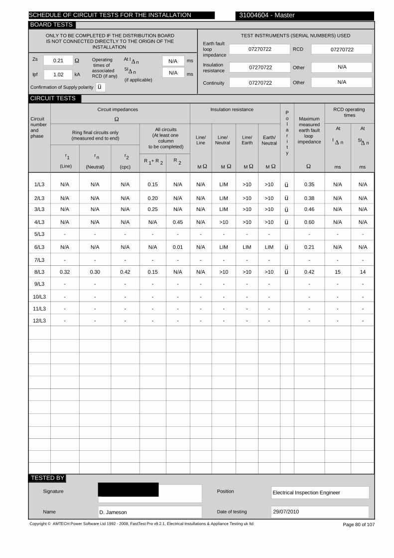
0.21
1.02
N/A
N/A
07270722
07270722
07270722
07270722
N/A
1/L3
2/L3
3/L3
4/L3
5/L3
6/L3
7/L3
8/L3
9/L3
10/L3
11/L3
12/L3
N/A
N/A
N/A
N/A
-
N/A
-
0.32
-
-
-
-
N/A
N/A
N/A
N/A
-
N/A
-
0.30
-
-
-
-
N/A
N/A
N/A
N/A
-
N/A
-
0.42
-
-
-
-
0.15
0.20
0.25
N/A
-
N/A
-
0.15
-
-
-
-
N/A
N/A
N/A
0.45
-
0.01
-
N/A
-
-
-
-
N/A
N/A
N/A
N/A
-
N/A
-
N/A
-
-
-
-
LIM
LIM
LIM
>10
-
LIM
-
>10
-
-
-
-
>10
>10
>10
>10
-
LIM
-
>10
-
-
-
-
>10
>10
>10
>10
-
LIM
-
>10
-
-
-
-
ü
ü
ü
ü
ü
ü
0.35
0.38
0.46
0.60
-
0.21
-
0.42
-
-
-
-
N/A N/A
N/A N/A
N/A N/A
N/A N/A
- -
N/A N/A
- -
15 14
- -
- -
- -
- -
Electrical Inspection Engineer
D. Jameson
Copyright © AMTECH Power Software Ltd 1992 - 2008, FastTest Pro v9.2.1, Electrical Instullations & Appliance Testing uk ltd
ONLY TO BE COMPLETED IF THE DISTRIBUTION BOARDIS NOT CONNECTED DIRECTLY TO THE ORIGIN OF THE
INSTALLATION
Zs
Ipf kA
Ω Operating times ofassociatedRCD (if any)
5I
(if applicable)
At I ∆ n ms
ms
N/A
TEST INSTRUMENTS (SERIAL NUMBERS) USED
Earth faultloopimpedance
Insulation resistance
Continuity
RCD
Other
Other
Circuitnumberandphase
Circuit impedances
Ω
Ring final circuits only(measured end to end)
r
(Line)
r
(Neutral)
r
(cpc)
1 2n
All circuits(At least one
columnto be completed)
R + R1 2 R 2
Insulation resistance
Line/Line
Line/Neutral
Line/Earth
Earth/Neutral
Polarity
Ω Ω Ω ΩMMMM
RCD operating times
Maximummeasuredearth fault
loop impedance
Ω msms
At
I ∆ n
Signature
Name
Position
Date of testing
31004604 - Master
Page 80 of 107
n∆
At
5I∆ n
29/07/2010
SCHEDULE OF CIRCUIT TESTS FOR THE INSTALLATION
CIRCUIT TESTS
TESTED BY
BOARD TESTS
Confirmation of Supply polarity ü
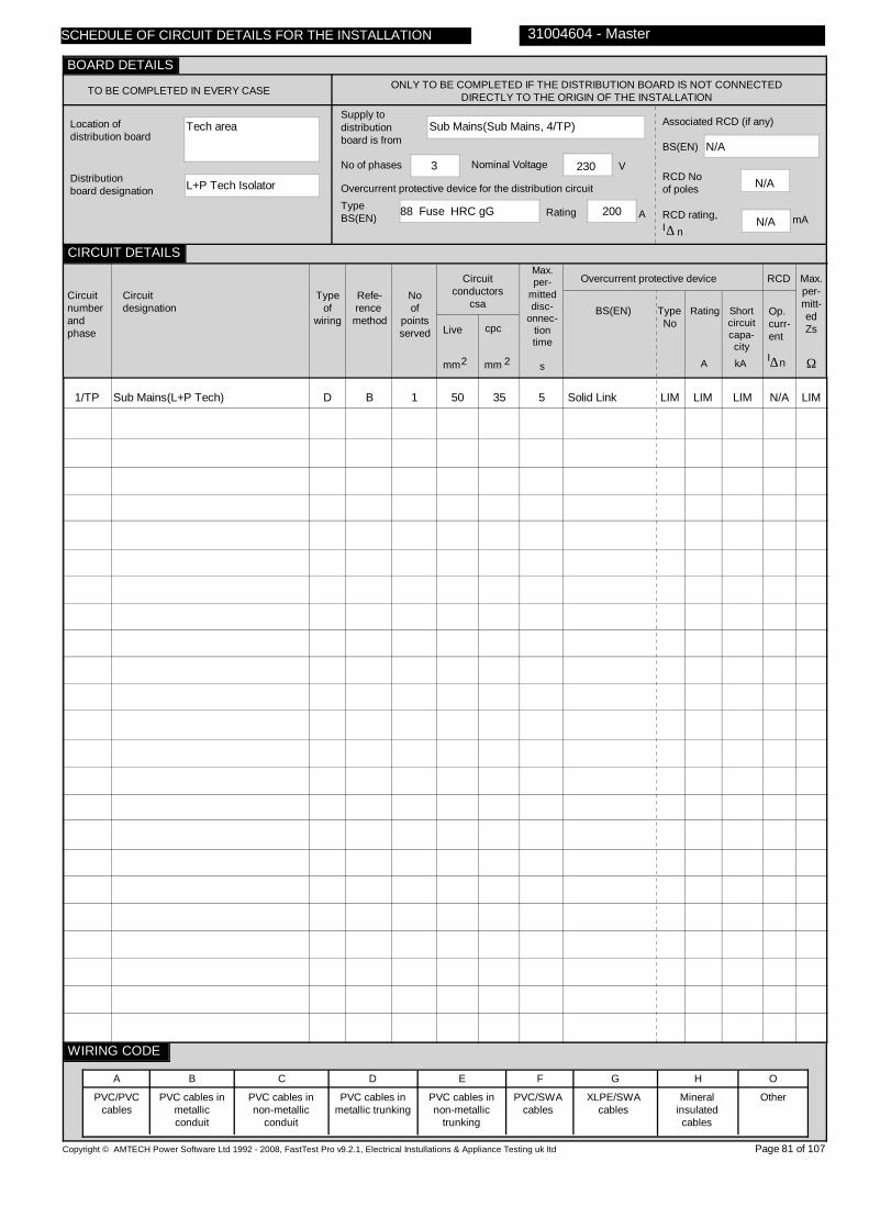
Tech area
L+P Tech Isolator
Sub Mains(Sub Mains, 4/TP)
88 Fuse HRC gG 200
3 230
N/A
N/A
N/A
1/TP
Sub Mains(L+P Tech)
D
B
1
50
35
5
Solid Link
LIM
LIM
LIM
N/A
LIM
Copyright © AMTECH Power Software Ltd 1992 - 2008, FastTest Pro v9.2.1, Electrical Instullations & Appliance Testing uk ltd
TO BE COMPLETED IN EVERY CASE ONLY TO BE COMPLETED IF THE DISTRIBUTION BOARD IS NOT CONNECTED DIRECTLY TO THE ORIGIN OF THE INSTALLATION
Location of distribution board
Distribution board designation
Supply to distributionboard is from
Overcurrent protective device for the distribution circuitTypeBS(EN) Rating A
No of phases Nominal Voltage V
Associated RCD (if any)
BS(EN)
RCD No of poles
RCD rating,I
mA∆ n
Circuitnumberandphase
Circuitdesignation
Typeof
wiring
Refe-rence method
Noof
pointsserved
Circuitconductors
csa
Live cpc
mm mm2 2
Max.per-
mitteddisc-
onnec-tiontime
s
Overcurrent protective device
BS(EN) Type No
Rating Shortcircuitcapa-city
RCD
Op.curr-ent
I∆n
Max.per-mitt-edZs
Ω
PVC/PVCcables
PVC cables in metallic conduit
PVC cables in non-metallic
conduit
PVC cables in metallic trunking
PVC cables in non-metallic
trunking
PVC/SWAcables
XLPE/SWAcables
Mineralinsulatedcables
Other
31004604 - Master
A B C D E F G H O
Page 81 of 107
SCHEDULE OF CIRCUIT DETAILS FOR THE INSTALLATION
CIRCUIT DETAILS
BOARD DETAILS
WIRING CODE
kAA

0.14
3.16
N/A
N/A
07270722
07270722
07270722
07270722
N/A
1/TP
N/A
N/A
N/A
N/A
0.01
>10
>10
>10
>10
ü
0.14
N/A N/A
Electrical Inspection Engineer
D. Jameson
Copyright © AMTECH Power Software Ltd 1992 - 2008, FastTest Pro v9.2.1, Electrical Instullations & Appliance Testing uk ltd
ONLY TO BE COMPLETED IF THE DISTRIBUTION BOARDIS NOT CONNECTED DIRECTLY TO THE ORIGIN OF THE
INSTALLATION
Zs
Ipf kA
Ω Operating times ofassociatedRCD (if any)
5I
(if applicable)
At I ∆ n ms
ms
N/A
TEST INSTRUMENTS (SERIAL NUMBERS) USED
Earth faultloopimpedance
Insulation resistance
Continuity
RCD
Other
Other
Circuitnumberandphase
Circuit impedances
Ω
Ring final circuits only(measured end to end)
r
(Line)
r
(Neutral)
r
(cpc)
1 2n
All circuits(At least one
columnto be completed)
R + R1 2 R 2
Insulation resistance
Line/Line
Line/Neutral
Line/Earth
Earth/Neutral
Polarity
Ω Ω Ω ΩMMMM
RCD operating times
Maximummeasuredearth fault
loop impedance
Ω msms
At
I ∆ n
Signature
Name
Position
Date of testing
31004604 - Master
Page 82 of 107
n∆
At
5I∆ n
29/07/2010
SCHEDULE OF CIRCUIT TESTS FOR THE INSTALLATION
CIRCUIT TESTS
TESTED BY
BOARD TESTS
Confirmation of Supply polarity ü

Tech stairs
L+P Tech
Sub Mains(L+P Tech Isolator, 1/TP)
Solid Link LIM LIM
3 400
N/A
N/A
N/A
1/TP
2/L1
2/L2
2/L3
3/L1
3/L2
3/L3
Sub Mains(DB Metalwork)
Cooker no.1
Sub Mains(DB 9)
Sub Mains(Stage DB 10)
SPARE
Home EC heaters
SPARE
H
D
D
H
-
D
-
C
B
B
C
-
B
-
1
1
1
1
-
3
-
6
10
16
16
-
10
-
Micc
TRUNK
16
Micc
-
TRUNK
-
5
5
5
5
-
5
-
88 Fuse HRC
88 Fuse HRC
88 Fuse HRC
88 Fuse HRC
-
88 Fuse HRC
-
gG
gG
gG
gG
-
gG
-
40
40
63
63
-
40
-
80
80
80
80
-
80
-
N/A
N/A
N/A
N/A
-
N/A
-
1.35
1.35
0.82
0.82
-
1.35
-
Copyright © AMTECH Power Software Ltd 1992 - 2008, FastTest Pro v9.2.1, Electrical Instullations & Appliance Testing uk ltd
TO BE COMPLETED IN EVERY CASE ONLY TO BE COMPLETED IF THE DISTRIBUTION BOARD IS NOT CONNECTED DIRECTLY TO THE ORIGIN OF THE INSTALLATION
Location of distribution board
Distribution board designation
Supply to distributionboard is from
Overcurrent protective device for the distribution circuitTypeBS(EN) Rating A
No of phases Nominal Voltage V
Associated RCD (if any)
BS(EN)
RCD No of poles
RCD rating,I
mA∆ n
Circuitnumberandphase
Circuitdesignation
Typeof
wiring
Refe-rence method
Noof
pointsserved
Circuitconductors
csa
Live cpc
mm mm2 2
Max.per-
mitteddisc-
onnec-tiontime
s
Overcurrent protective device
BS(EN) Type No
Rating Shortcircuitcapa-city
RCD
Op.curr-ent
I∆n
Max.per-mitt-edZs
Ω
PVC/PVCcables
PVC cables in metallic conduit
PVC cables in non-metallic
conduit
PVC cables in metallic trunking
PVC cables in non-metallic
trunking
PVC/SWAcables
XLPE/SWAcables
Mineralinsulatedcables
Other
31004604 - Master
A B C D E F G H O
Page 83 of 107
SCHEDULE OF CIRCUIT DETAILS FOR THE INSTALLATION
CIRCUIT DETAILS
BOARD DETAILS
WIRING CODE
kAA

0.14
3.16
N/A
N/A
07270722
07270722
07270722
07270722
N/A
1/TP
2/L1
2/L2
2/L3
3/L1
3/L2
3/L3
N/A
N/A
N/A
N/A
-
N/A
-
N/A
N/A
N/A
N/A
-
N/A
-
N/A
N/A
N/A
N/A
-
N/A
-
N/A
0.02
N/A
0.06
-
0.01
-
0.03
N/A
0.04
N/A
-
N/A
-
>10
N/A
N/A
N/A
-
N/A
-
>10
>10
>10
>10
-
>10
-
>10
>10
>10
>10
-
>10
-
>10
>10
>10
>10
-
>10
-
ü
ü
ü
ü
ü
0.16
0.14
0.16
0.18
-
0.14
-
N/A N/A
N/A N/A
N/A N/A
N/A N/A
- -
N/A N/A
- -
Electrical Inspection Engineer
D. Jameson
Copyright © AMTECH Power Software Ltd 1992 - 2008, FastTest Pro v9.2.1, Electrical Instullations & Appliance Testing uk ltd
ONLY TO BE COMPLETED IF THE DISTRIBUTION BOARDIS NOT CONNECTED DIRECTLY TO THE ORIGIN OF THE
INSTALLATION
Zs
Ipf kA
Ω Operating times ofassociatedRCD (if any)
5I
(if applicable)
At I ∆ n ms
ms
N/A
TEST INSTRUMENTS (SERIAL NUMBERS) USED
Earth faultloopimpedance
Insulation resistance
Continuity
RCD
Other
Other
Circuitnumberandphase
Circuit impedances
Ω
Ring final circuits only(measured end to end)
r
(Line)
r
(Neutral)
r
(cpc)
1 2n
All circuits(At least one
columnto be completed)
R + R1 2 R 2
Insulation resistance
Line/Line
Line/Neutral
Line/Earth
Earth/Neutral
Polarity
Ω Ω Ω ΩMMMM
RCD operating times
Maximummeasuredearth fault
loop impedance
Ω msms
At
I ∆ n
Signature
Name
Position
Date of testing
31004604 - Master
Page 84 of 107
n∆
At
5I∆ n
29/07/2010
SCHEDULE OF CIRCUIT TESTS FOR THE INSTALLATION
CIRCUIT TESTS
TESTED BY
BOARD TESTS
Confirmation of Supply polarity ü

Metalwork
DB Metalwork
Sub Mains(L+P Tech, 1/TP)
88 Fuse HRC gG 40
3 400
N/A
N/A
N/A
1/TP
2/TP
3/TP
4/TP
5/TP
6/TP
7/TP
8/TP
9/TP
10/TP
11/L1
11/L2
11/L3
12/TP
Unused isolator
Unused isolator
Unable to locate
Unable to locate
Drill
SPARE
Unused isolator
Unused isolator
Unused isolator
Unable to locate
Water heater
Gas guard
Sockets via RCD
SPARE
B
B
B
B
B
-
B
B
B
B
B
B
B
-
B
B
B
B
B
-
B
B
B
B
B
B
B
-
1
1
N/V
N/V
1
-
1
1
1
N/V
1
1
6
-
2.5
2.5
2.5
2.5
2.5
-
2.5
2.5
2.5
2.5
2.5
2.5
4
-
2.5
2.5
2.5
2.5
2.5
-
2.5
2.5
2.5
1.5
2.5
COND
4
-
0.4
0.4
0.4
0.4
0.4
-
0.4
0.4
0.4
0.4
0.4
0.4
0.4
-
3871 MCB
3871 MCB
3871 MCB
3871 MCB
3871 MCB
-
3871 MCB
3871 MCB
60898 MCB
3871 MCB
3871 MCB
3871 MCB
3871 MCB
-
2
2
2
2
2
-
2
2
B
2
2
2
2
-
10
10
10
10
10
-
10
10
16
10
16
32
32
-
9
9
9
9
9
-
9
9
9
9
9
9
9
-
N/A
N/A
N/A
N/A
N/A
-
N/A
N/A
N/A
N/A
N/A
N/A
30
-
3.29
3.29
3.29
3.29
3.29
-
3.29
3.29
2.88
3.29
2.05
1.03
1.03
-
Copyright © AMTECH Power Software Ltd 1992 - 2008, FastTest Pro v9.2.1, Electrical Instullations & Appliance Testing uk ltd
TO BE COMPLETED IN EVERY CASE ONLY TO BE COMPLETED IF THE DISTRIBUTION BOARD IS NOT CONNECTED DIRECTLY TO THE ORIGIN OF THE INSTALLATION
Location of distribution board
Distribution board designation
Supply to distributionboard is from
Overcurrent protective device for the distribution circuitTypeBS(EN) Rating A
No of phases Nominal Voltage V
Associated RCD (if any)
BS(EN)
RCD No of poles
RCD rating,I
mA∆ n
Circuitnumberandphase
Circuitdesignation
Typeof
wiring
Refe-rence method
Noof
pointsserved
Circuitconductors
csa
Live cpc
mm mm2 2
Max.per-
mitteddisc-
onnec-tiontime
s
Overcurrent protective device
BS(EN) Type No
Rating Shortcircuitcapa-city
RCD
Op.curr-ent
I∆n
Max.per-mitt-edZs
Ω
PVC/PVCcables
PVC cables in metallic conduit
PVC cables in non-metallic
conduit
PVC cables in metallic trunking
PVC cables in non-metallic
trunking
PVC/SWAcables
XLPE/SWAcables
Mineralinsulatedcables
Other
31004604 - Master
A B C D E F G H O
Page 85 of 107
SCHEDULE OF CIRCUIT DETAILS FOR THE INSTALLATION
CIRCUIT DETAILS
BOARD DETAILS
WIRING CODE
kAA

0.16
2.96
N/A
N/A
07270722
07270722
07270722
07270722
N/A
1/TP
2/TP
3/TP
4/TP
5/TP
6/TP
7/TP
8/TP
9/TP
10/TP
11/L1
11/L2
11/L3
12/TP
N/A
N/A
UNABLE
UNABLE
N/A
-
N/A
N/A
N/A
UNABLE
N/A
LIM
0.57
-
N/A
N/A
TO
TO
N/A
-
N/A
N/A
N/A
TO
N/A
LIM
0.57
-
N/A
N/A
LOCATE
LOCATE
N/A
-
N/A
N/A
N/A
LOCATE
N/A
LIM
0.07
-
0.16
0.14
LIM
LIM
0.09
-
0.15
0.13
0.15
LIM
0.22
N/A
0.10
-
N/A
N/A
LIM
LIM
N/A
-
N/A
N/A
N/A
LIM
N/A
0.22
N/A
-
>10
>10
LIM
LIM
>10
-
>10
>10
>10
LIM
N/A
N/A
N/A
-
>10
>10
LIM
LIM
>10
-
>10
>10
>10
LIM
>10
LIM
>10
-
>10
>10
LIM
LIM
>10
-
>10
>10
>10
LIM
>10
LIM
>10
-
>10
LIM
>10
LIM
>10
-
>10
>10
>10
LIM
>10
LIM
>10
-
ü
ü
ü
ü
ü
ü
ü
ü
ü
0.32
0.30
LIM
LIM
0.23
-
0.32
0.28
0.30
LIM
0.35
0.52
0.28
-
N/A N/A
N/A N/A
N/A N/A
N/A N/A
N/A N/A
- -
N/A N/A
N/A N/A
N/A N/A
N/A N/A
N/A N/A
N/A N/A
28 8
- -
Electrical Inspection Engineer
D. Jameson
Copyright © AMTECH Power Software Ltd 1992 - 2008, FastTest Pro v9.2.1, Electrical Instullations & Appliance Testing uk ltd
ONLY TO BE COMPLETED IF THE DISTRIBUTION BOARDIS NOT CONNECTED DIRECTLY TO THE ORIGIN OF THE
INSTALLATION
Zs
Ipf kA
Ω Operating times ofassociatedRCD (if any)
5I
(if applicable)
At I ∆ n ms
ms
N/A
TEST INSTRUMENTS (SERIAL NUMBERS) USED
Earth faultloopimpedance
Insulation resistance
Continuity
RCD
Other
Other
Circuitnumberandphase
Circuit impedances
Ω
Ring final circuits only(measured end to end)
r
(Line)
r
(Neutral)
r
(cpc)
1 2n
All circuits(At least one
columnto be completed)
R + R1 2 R 2
Insulation resistance
Line/Line
Line/Neutral
Line/Earth
Earth/Neutral
Polarity
Ω Ω Ω ΩMMMM
RCD operating times
Maximummeasuredearth fault
loop impedance
Ω msms
At
I ∆ n
Signature
Name
Position
Date of testing
31004604 - Master
Page 86 of 107
n∆
At
5I∆ n
29/07/2010
SCHEDULE OF CIRCUIT TESTS FOR THE INSTALLATION
CIRCUIT TESTS
TESTED BY
BOARD TESTS
Confirmation of Supply polarity ü
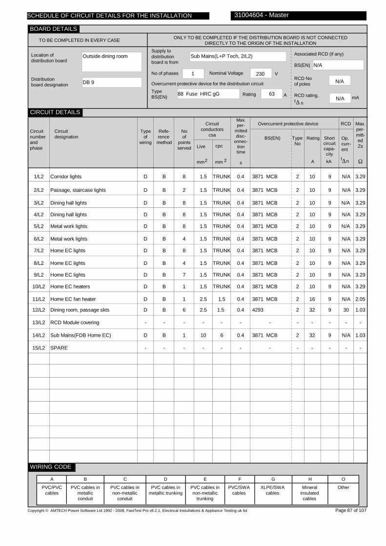
Outside dining room
DB 9
Sub Mains(L+P Tech, 2/L2)
88 Fuse HRC gG 63
1 230
N/A
N/A
N/A
1/L2
2/L2
3/L2
4/L2
5/L2
6/L2
7/L2
8/L2
9/L2
10/L2
11/L2
12/L2
13/L2
14/L2
15/L2
Corridor lights
Passage, staircase lights
Dining hall lights
Dining hall lights
Metal work lights
Metal work lights
Home EC lights
Home EC lights
Home EC lights
Home EC heaters
Home EC fan heater
Dining room, passage skts
RCD Module covering
Sub Mains(FDB Home EC)
SPARE
D
D
D
D
D
D
D
D
D
D
D
D
-
D
-
B
B
B
B
B
B
B
B
B
B
B
B
-
B
-
8
2
8
8
8
4
8
4
7
1
1
6
-
1
-
1.5
1.5
1.5
1.5
1.5
1.5
1.5
1.5
1.5
1.5
2.5
2.5
-
10
-
TRUNK
TRUNK
TRUNK
TRUNK
TRUNK
TRUNK
TRUNK
TRUNK
TRUNK
1.5
TRUNK
1.5
-
6
-
0.4
0.4
0.4
0.4
0.4
0.4
0.4
0.4
0.4
0.4
0.4
0.4
-
0.4
-
3871 MCB
3871 MCB
3871 MCB
3871 MCB
3871 MCB
3871 MCB
3871 MCB
3871 MCB
3871 MCB
3871 MCB
3871 MCB
4293
-
3871 MCB
-
2
2
2
2
2
2
2
2
2
2
2
2
-
2
-
10
10
10
10
10
10
10
10
10
10
16
32
-
32
-
9
9
9
9
9
9
9
9
9
9
9
9
-
9
-
N/A
N/A
N/A
N/A
N/A
N/A
N/A
N/A
N/A
N/A
N/A
30
-
N/A
-
3.29
3.29
3.29
3.29
3.29
3.29
3.29
3.29
3.29
3.29
2.05
1.03
-
1.03
-
Copyright © AMTECH Power Software Ltd 1992 - 2008, FastTest Pro v9.2.1, Electrical Instullations & Appliance Testing uk ltd
TO BE COMPLETED IN EVERY CASE ONLY TO BE COMPLETED IF THE DISTRIBUTION BOARD IS NOT CONNECTED DIRECTLY TO THE ORIGIN OF THE INSTALLATION
Location of distribution board
Distribution board designation
Supply to distributionboard is from
Overcurrent protective device for the distribution circuitTypeBS(EN) Rating A
No of phases Nominal Voltage V
Associated RCD (if any)
BS(EN)
RCD No of poles
RCD rating,I
mA∆ n
Circuitnumberandphase
Circuitdesignation
Typeof
wiring
Refe-rence method
Noof
pointsserved
Circuitconductors
csa
Live cpc
mm mm2 2
Max.per-
mitteddisc-
onnec-tiontime
s
Overcurrent protective device
BS(EN) Type No
Rating Shortcircuitcapa-city
RCD
Op.curr-ent
I∆n
Max.per-mitt-edZs
Ω
PVC/PVCcables
PVC cables in metallic conduit
PVC cables in non-metallic
conduit
PVC cables in metallic trunking
PVC cables in non-metallic
trunking
PVC/SWAcables
XLPE/SWAcables
Mineralinsulatedcables
Other
31004604 - Master
A B C D E F G H O
Page 87 of 107
SCHEDULE OF CIRCUIT DETAILS FOR THE INSTALLATION
CIRCUIT DETAILS
BOARD DETAILS
WIRING CODE
kAA

0.16
1.42
N/A
N/A
07270722
07270722
07270722
07270722
N/A
1/L2
2/L2
3/L2
4/L2
5/L2
6/L2
7/L2
8/L2
9/L2
10/L2
11/L2
12/L2
13/L2
14/L2
15/L2
N/A
N/A
N/A
N/A
N/A
N/A
N/A
N/A
N/A
N/A
N/A
0.34
-
N/A
-
N/A
N/A
N/A
N/A
N/A
N/A
N/A
N/A
N/A
N/A
N/A
0.36
-
N/A
-
N/A
N/A
N/A
N/A
N/A
N/A
N/A
N/A
N/A
N/A
N/A
0.09
-
N/A
-
N/A
N/A
N/A
N/A
N/A
N/A
N/A
N/A
N/A
N/A
0.34
0.08
-
N/A
-
0.02
0.04
0.07
0.07
0.13
0.14
0.06
0.07
0.09
0.15
N/A
N/A
-
0.02
-
N/A
N/A
N/A
N/A
N/A
N/A
N/A
N/A
N/A
N/A
N/A
N/A
-
N/A
-
LIM
LIM
LIM
LIM
LIM
LIM
LIM
LIM
LIM
>10
>10
>10
-
>10
-
>10
>10
>10
>10
>10
>10
>10
>10
>10
>10
>10
>10
-
>10
-
>10
>10
>10
>10
>10
>10
>10
>10
>10
>10
>10
>10
-
>10
-
ü
ü
ü
ü
ü
ü
ü
ü
ü
ü
ü
ü
ü
0.21
0.22
0.20
0.24
0.33
0.39
0.39
0.36
0.28
0.36
0.60
0.69
-
0.07
-
N/A N/A
N/A N/A
N/A N/A
N/A N/A
N/A N/A
N/A N/A
N/A N/A
N/A N/A
N/A N/A
N/A N/A
N/A N/A
47 23
- -
N/A N/A
- -
Electrical Inspection Engineer
D. Jameson
Copyright © AMTECH Power Software Ltd 1992 - 2008, FastTest Pro v9.2.1, Electrical Instullations & Appliance Testing uk ltd
ONLY TO BE COMPLETED IF THE DISTRIBUTION BOARDIS NOT CONNECTED DIRECTLY TO THE ORIGIN OF THE
INSTALLATION
Zs
Ipf kA
Ω Operating times ofassociatedRCD (if any)
5I
(if applicable)
At I ∆ n ms
ms
N/A
TEST INSTRUMENTS (SERIAL NUMBERS) USED
Earth faultloopimpedance
Insulation resistance
Continuity
RCD
Other
Other
Circuitnumberandphase
Circuit impedances
Ω
Ring final circuits only(measured end to end)
r
(Line)
r
(Neutral)
r
(cpc)
1 2n
All circuits(At least one
columnto be completed)
R + R1 2 R 2
Insulation resistance
Line/Line
Line/Neutral
Line/Earth
Earth/Neutral
Polarity
Ω Ω Ω ΩMMMM
RCD operating times
Maximummeasuredearth fault
loop impedance
Ω msms
At
I ∆ n
Signature
Name
Position
Date of testing
31004604 - Master
Page 88 of 107
n∆
At
5I∆ n
29/07/2010
SCHEDULE OF CIRCUIT TESTS FOR THE INSTALLATION
CIRCUIT TESTS
TESTED BY
BOARD TESTS
Confirmation of Supply polarity ü

Home economics
FDB Home EC
Sub Mains(DB 9, 14/L2)
3871 MCB 2 32
1 230
4293 RCD
2
30
1/L2
Home econ & back rm skts
H
C
14
2.5
Micc
0.4
4293
N/V
30
2.5
30
N/V
Copyright © AMTECH Power Software Ltd 1992 - 2008, FastTest Pro v9.2.1, Electrical Instullations & Appliance Testing uk ltd
TO BE COMPLETED IN EVERY CASE ONLY TO BE COMPLETED IF THE DISTRIBUTION BOARD IS NOT CONNECTED DIRECTLY TO THE ORIGIN OF THE INSTALLATION
Location of distribution board
Distribution board designation
Supply to distributionboard is from
Overcurrent protective device for the distribution circuitTypeBS(EN) Rating A
No of phases Nominal Voltage V
Associated RCD (if any)
BS(EN)
RCD No of poles
RCD rating,I
mA∆ n
Circuitnumberandphase
Circuitdesignation
Typeof
wiring
Refe-rence method
Noof
pointsserved
Circuitconductors
csa
Live cpc
mm mm2 2
Max.per-
mitteddisc-
onnec-tiontime
s
Overcurrent protective device
BS(EN) Type No
Rating Shortcircuitcapa-city
RCD
Op.curr-ent
I∆n
Max.per-mitt-edZs
Ω
PVC/PVCcables
PVC cables in metallic conduit
PVC cables in non-metallic
conduit
PVC cables in metallic trunking
PVC cables in non-metallic
trunking
PVC/SWAcables
XLPE/SWAcables
Mineralinsulatedcables
Other
31004604 - Master
A B C D E F G H O
Page 89 of 107
SCHEDULE OF CIRCUIT DETAILS FOR THE INSTALLATION
CIRCUIT DETAILS
BOARD DETAILS
WIRING CODE
kAA

0.07
3.32
N/A
N/A
0707070985
0707070985
0707070985
0707070985
N/A
1/L2
0.31
0.30
0.08
N/A
0.08
N/A
>10
>10
>10
ü
0.46
40 8
Electrical Inspection Engineer
D. Jameson
Copyright © AMTECH Power Software Ltd 1992 - 2008, FastTest Pro v9.2.1, Electrical Instullations & Appliance Testing uk ltd
ONLY TO BE COMPLETED IF THE DISTRIBUTION BOARDIS NOT CONNECTED DIRECTLY TO THE ORIGIN OF THE
INSTALLATION
Zs
Ipf kA
Ω Operating times ofassociatedRCD (if any)
5I
(if applicable)
At I ∆ n ms
ms
N/A
TEST INSTRUMENTS (SERIAL NUMBERS) USED
Earth faultloopimpedance
Insulation resistance
Continuity
RCD
Other
Other
Circuitnumberandphase
Circuit impedances
Ω
Ring final circuits only(measured end to end)
r
(Line)
r
(Neutral)
r
(cpc)
1 2n
All circuits(At least one
columnto be completed)
R + R1 2 R 2
Insulation resistance
Line/Line
Line/Neutral
Line/Earth
Earth/Neutral
Polarity
Ω Ω Ω ΩMMMM
RCD operating times
Maximummeasuredearth fault
loop impedance
Ω msms
At
I ∆ n
Signature
Name
Position
Date of testing
31004604 - Master
Page 90 of 107
n∆
At
5I∆ n
29/07/2010
SCHEDULE OF CIRCUIT TESTS FOR THE INSTALLATION
CIRCUIT TESTS
TESTED BY
BOARD TESTS
Confirmation of Supply polarity ü
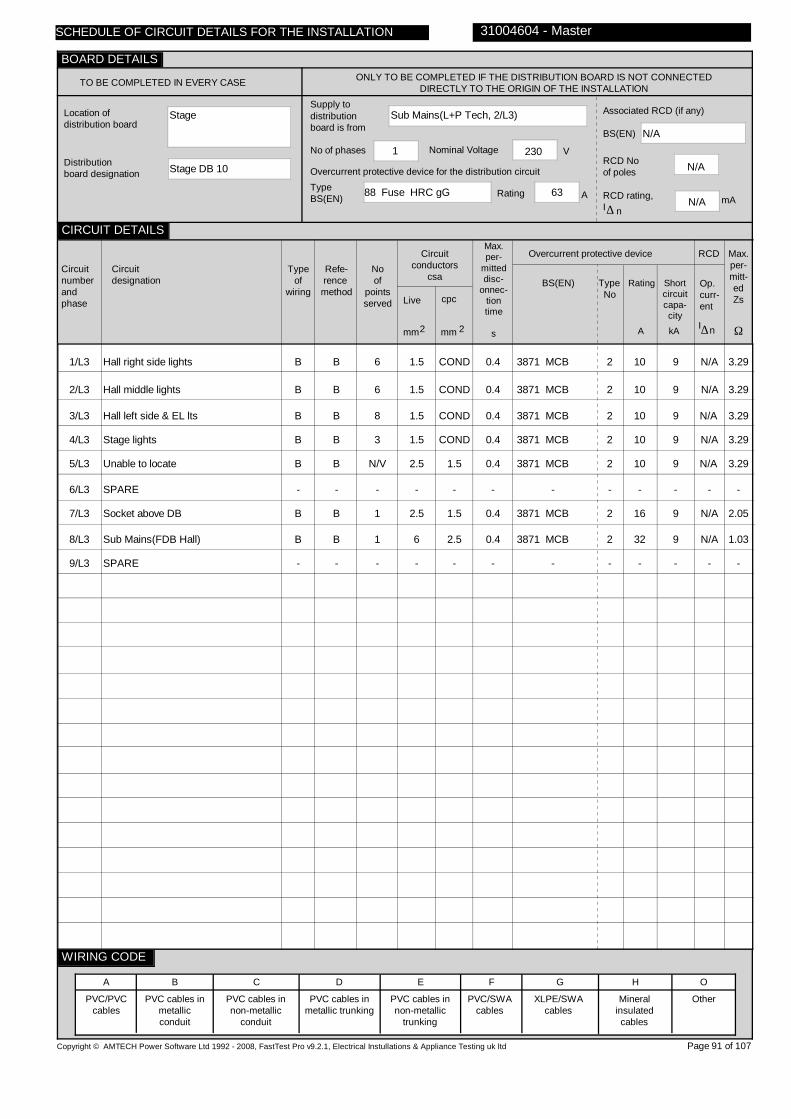
Stage
Stage DB 10
Sub Mains(L+P Tech, 2/L3)
88 Fuse HRC gG 63
1 230
N/A
N/A
N/A
1/L3
2/L3
3/L3
4/L3
5/L3
6/L3
7/L3
8/L3
9/L3
Hall right side lights
Hall middle lights
Hall left side & EL lts
Stage lights
Unable to locate
SPARE
Socket above DB
Sub Mains(FDB Hall)
SPARE
B
B
B
B
B
-
B
B
-
B
B
B
B
B
-
B
B
-
6
6
8
3
N/V
-
1
1
-
1.5
1.5
1.5
1.5
2.5
-
2.5
6
-
COND
COND
COND
COND
1.5
-
1.5
2.5
-
0.4
0.4
0.4
0.4
0.4
-
0.4
0.4
-
3871 MCB
3871 MCB
3871 MCB
3871 MCB
3871 MCB
-
3871 MCB
3871 MCB
-
2
2
2
2
2
-
2
2
-
10
10
10
10
10
-
16
32
-
9
9
9
9
9
-
9
9
-
N/A
N/A
N/A
N/A
N/A
-
N/A
N/A
-
3.29
3.29
3.29
3.29
3.29
-
2.05
1.03
-
Copyright © AMTECH Power Software Ltd 1992 - 2008, FastTest Pro v9.2.1, Electrical Instullations & Appliance Testing uk ltd
TO BE COMPLETED IN EVERY CASE ONLY TO BE COMPLETED IF THE DISTRIBUTION BOARD IS NOT CONNECTED DIRECTLY TO THE ORIGIN OF THE INSTALLATION
Location of distribution board
Distribution board designation
Supply to distributionboard is from
Overcurrent protective device for the distribution circuitTypeBS(EN) Rating A
No of phases Nominal Voltage V
Associated RCD (if any)
BS(EN)
RCD No of poles
RCD rating,I
mA∆ n
Circuitnumberandphase
Circuitdesignation
Typeof
wiring
Refe-rence method
Noof
pointsserved
Circuitconductors
csa
Live cpc
mm mm2 2
Max.per-
mitteddisc-
onnec-tiontime
s
Overcurrent protective device
BS(EN) Type No
Rating Shortcircuitcapa-city
RCD
Op.curr-ent
I∆n
Max.per-mitt-edZs
Ω
PVC/PVCcables
PVC cables in metallic conduit
PVC cables in non-metallic
conduit
PVC cables in metallic trunking
PVC cables in non-metallic
trunking
PVC/SWAcables
XLPE/SWAcables
Mineralinsulatedcables
Other
31004604 - Master
A B C D E F G H O
Page 91 of 107
SCHEDULE OF CIRCUIT DETAILS FOR THE INSTALLATION
CIRCUIT DETAILS
BOARD DETAILS
WIRING CODE
kAA

0.18
1.18
N/A
N/A
07270722
07270722
07270722
07270722
N/A
1/L3
2/L3
3/L3
4/L3
5/L3
6/L3
7/L3
8/L3
9/L3
N/A
N/A
N/A
N/A
UNABLE
-
N/A
N/A
-
N/A
N/A
N/A
N/A
TO
-
N/A
N/A
-
N/A
N/A
N/A
N/A
LOCATE
-
N/A
N/A
-
N/A
N/A
N/A
N/A
LIM
-
N/A
N/A
-
0.21
0.10
0.06
0.13
LIM
-
0.04
0.02
-
N/A
N/A
N/A
N/A
N/A
-
N/A
N/A
-
LIM
LIM
LIM
LIM
LIM
-
>10
>10
-
>10
>10
>10
>10
LIM
-
>10
>10
-
>10
>10
>10
>10
LIM
-
>10
>10
-
ü
ü
ü
ü
ü
ü
0.39
0.28
0.22
0.40
LIM
-
0.20
0.20
-
N/A N/A
N/A N/A
N/A N/A
N/A N/A
N/A N/A
- -
N/A N/A
N/A N/A
- -
Electrical Inspection Engineer
D. Jameson
Copyright © AMTECH Power Software Ltd 1992 - 2008, FastTest Pro v9.2.1, Electrical Instullations & Appliance Testing uk ltd
ONLY TO BE COMPLETED IF THE DISTRIBUTION BOARDIS NOT CONNECTED DIRECTLY TO THE ORIGIN OF THE
INSTALLATION
Zs
Ipf kA
Ω Operating times ofassociatedRCD (if any)
5I
(if applicable)
At I ∆ n ms
ms
N/A
TEST INSTRUMENTS (SERIAL NUMBERS) USED
Earth faultloopimpedance
Insulation resistance
Continuity
RCD
Other
Other
Circuitnumberandphase
Circuit impedances
Ω
Ring final circuits only(measured end to end)
r
(Line)
r
(Neutral)
r
(cpc)
1 2n
All circuits(At least one
columnto be completed)
R + R1 2 R 2
Insulation resistance
Line/Line
Line/Neutral
Line/Earth
Earth/Neutral
Polarity
Ω Ω Ω ΩMMMM
RCD operating times
Maximummeasuredearth fault
loop impedance
Ω msms
At
I ∆ n
Signature
Name
Position
Date of testing
31004604 - Master
Page 92 of 107
n∆
At
5I∆ n
29/07/2010
SCHEDULE OF CIRCUIT TESTS FOR THE INSTALLATION
CIRCUIT TESTS
TESTED BY
BOARD TESTS
Confirmation of Supply polarity ü

Stage
FDB Hall
Sub Mains(Stage DB 10, 8/L3)
3871 MCB 2 32
1 230
4293 RCD
2
30
1/L3
Hall sockets
B
B
12
2.5
COND
0.4
4293
2
30
25
30
1.09
Copyright © AMTECH Power Software Ltd 1992 - 2008, FastTest Pro v9.2.1, Electrical Instullations & Appliance Testing uk ltd
TO BE COMPLETED IN EVERY CASE ONLY TO BE COMPLETED IF THE DISTRIBUTION BOARD IS NOT CONNECTED DIRECTLY TO THE ORIGIN OF THE INSTALLATION
Location of distribution board
Distribution board designation
Supply to distributionboard is from
Overcurrent protective device for the distribution circuitTypeBS(EN) Rating A
No of phases Nominal Voltage V
Associated RCD (if any)
BS(EN)
RCD No of poles
RCD rating,I
mA∆ n
Circuitnumberandphase
Circuitdesignation
Typeof
wiring
Refe-rence method
Noof
pointsserved
Circuitconductors
csa
Live cpc
mm mm2 2
Max.per-
mitteddisc-
onnec-tiontime
s
Overcurrent protective device
BS(EN) Type No
Rating Shortcircuitcapa-city
RCD
Op.curr-ent
I∆n
Max.per-mitt-edZs
Ω
PVC/PVCcables
PVC cables in metallic conduit
PVC cables in non-metallic
conduit
PVC cables in metallic trunking
PVC cables in non-metallic
trunking
PVC/SWAcables
XLPE/SWAcables
Mineralinsulatedcables
Other
31004604 - Master
A B C D E F G H O
Page 93 of 107
SCHEDULE OF CIRCUIT DETAILS FOR THE INSTALLATION
CIRCUIT DETAILS
BOARD DETAILS
WIRING CODE
kAA

0.20
1.17
24
8
07270722
07270722
07270722
07270722
N/A
1/L3
0.44
0.44
0.11
N/A
0.11
N/A
>10
>10
>10
ü
0.31
24 8
Electrical Inspection Engineer
D. Jameson
Copyright © AMTECH Power Software Ltd 1992 - 2008, FastTest Pro v9.2.1, Electrical Instullations & Appliance Testing uk ltd
ONLY TO BE COMPLETED IF THE DISTRIBUTION BOARDIS NOT CONNECTED DIRECTLY TO THE ORIGIN OF THE
INSTALLATION
Zs
Ipf kA
Ω Operating times ofassociatedRCD (if any)
5I
(if applicable)
At I ∆ n ms
ms
N/A
TEST INSTRUMENTS (SERIAL NUMBERS) USED
Earth faultloopimpedance
Insulation resistance
Continuity
RCD
Other
Other
Circuitnumberandphase
Circuit impedances
Ω
Ring final circuits only(measured end to end)
r
(Line)
r
(Neutral)
r
(cpc)
1 2n
All circuits(At least one
columnto be completed)
R + R1 2 R 2
Insulation resistance
Line/Line
Line/Neutral
Line/Earth
Earth/Neutral
Polarity
Ω Ω Ω ΩMMMM
RCD operating times
Maximummeasuredearth fault
loop impedance
Ω msms
At
I ∆ n
Signature
Name
Position
Date of testing
31004604 - Master
Page 94 of 107
n∆
At
5I∆ n
29/07/2010
SCHEDULE OF CIRCUIT TESTS FOR THE INSTALLATION
CIRCUIT TESTS
TESTED BY
BOARD TESTS
Confirmation of Supply polarity ü

Kitchen store
DB Kitchen (Old)
Sub Mains(Sub Mains, 5/L1)
88 Fuse HRC gG 63
1 230
N/A
N/A
N/A
1/L1
2/L1
3/L1
4/L1
5/L1
6/L1
7/L1
8/L1
9/L1
10/L1
11/L1
12/L1
13/L1
14/L1
15/L1
SPARE
Kitchen (old) lights
Unable to locate
Corridors & stores lights
Unable to locate
SPARE
Fan no.1
Fan no.2
Unable to locate
Large freezer socket
Freezer chest socket
Mixer
RCD socket
Office heater
Staff room heater
-
D/B
D/B
D/B
H
-
D/B
D/B
D/B
D/B
D/B
D/B
D/B
H
D/B
-
B
B
B
C
-
B
B
B
B
B
B
B
C
B
-
9
N/V
8
N/V
-
1
1
N/V
1
1
1
1
1
1
-
1.5
1.5
1.5
1.5
-
2.5
2.5
2.5
2.5
2.5
2.5
2.5
1.5
2.5
-
1.5
1.5
1.5
1.5
-
1.5
1.5
1.5
1.5
1.5
1.5
1.5
1.5
1.5
-
0.4
0.4
0.4
0.4
-
0.4
0.4
0.4
0.4
0.4
0.4
0.4
0.4
0.4
-
3871 MCB
3871 MCB
3871 MCB
3871 MCB
-
3871 MCB
3871 MCB
3871 MCB
3871 MCB
3871 MCB
3871 MCB
3871 MCB
3871 MCB
3871 MCB
-
2
2
2
2
-
2
2
2
2
2
2
2
2
2
-
10
10
10
10
-
10
10
10
10
10
16
16
16
10
-
9
9
9
9
-
9
9
9
9
9
9
9
9
9
-
N/A
N/A
N/A
N/A
-
N/A
N/A
N/A
N/A
N/A
N/A
30
N/A
N/A
-
3.29
3.29
3.29
3.29
-
3.29
3.29
3.29
3.29
3.29
2.05
2.05
2.05
3.29
Copyright © AMTECH Power Software Ltd 1992 - 2008, FastTest Pro v9.2.1, Electrical Instullations & Appliance Testing uk ltd
TO BE COMPLETED IN EVERY CASE ONLY TO BE COMPLETED IF THE DISTRIBUTION BOARD IS NOT CONNECTED DIRECTLY TO THE ORIGIN OF THE INSTALLATION
Location of distribution board
Distribution board designation
Supply to distributionboard is from
Overcurrent protective device for the distribution circuitTypeBS(EN) Rating A
No of phases Nominal Voltage V
Associated RCD (if any)
BS(EN)
RCD No of poles
RCD rating,I
mA∆ n
Circuitnumberandphase
Circuitdesignation
Typeof
wiring
Refe-rence method
Noof
pointsserved
Circuitconductors
csa
Live cpc
mm mm2 2
Max.per-
mitteddisc-
onnec-tiontime
s
Overcurrent protective device
BS(EN) Type No
Rating Shortcircuitcapa-city
RCD
Op.curr-ent
I∆n
Max.per-mitt-edZs
Ω
PVC/PVCcables
PVC cables in metallic conduit
PVC cables in non-metallic
conduit
PVC cables in metallic trunking
PVC cables in non-metallic
trunking
PVC/SWAcables
XLPE/SWAcables
Mineralinsulatedcables
Other
31004604 - Master
A B C D E F G H O
Page 95 of 107
SCHEDULE OF CIRCUIT DETAILS FOR THE INSTALLATION
CIRCUIT DETAILS
BOARD DETAILS
WIRING CODE
kAA
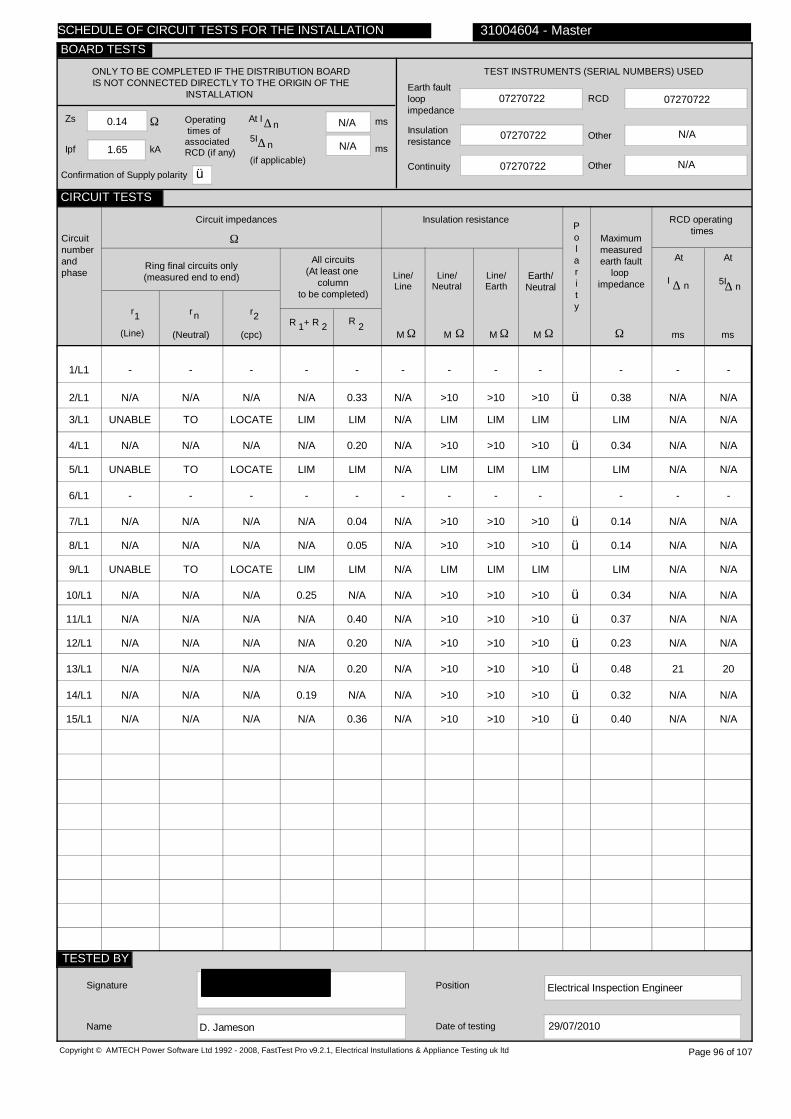
0.14
1.65
N/A
N/A
07270722
07270722
07270722
07270722
N/A
1/L1
2/L1
3/L1
4/L1
5/L1
6/L1
7/L1
8/L1
9/L1
10/L1
11/L1
12/L1
13/L1
14/L1
15/L1
-
N/A
UNABLE
N/A
UNABLE
-
N/A
N/A
UNABLE
N/A
N/A
N/A
N/A
N/A
N/A
-
N/A
TO
N/A
TO
-
N/A
N/A
TO
N/A
N/A
N/A
N/A
N/A
N/A
-
N/A
LOCATE
N/A
LOCATE
-
N/A
N/A
LOCATE
N/A
N/A
N/A
N/A
N/A
N/A
-
N/A
LIM
N/A
LIM
-
N/A
N/A
LIM
0.25
N/A
N/A
N/A
0.19
N/A
-
0.33
LIM
0.20
LIM
-
0.04
0.05
LIM
N/A
0.40
0.20
0.20
N/A
0.36
-
N/A
N/A
N/A
N/A
-
N/A
N/A
N/A
N/A
N/A
N/A
N/A
N/A
N/A
-
>10
LIM
>10
LIM
-
>10
>10
LIM
>10
>10
>10
>10
>10
>10
-
>10
LIM
>10
LIM
-
>10
>10
LIM
>10
>10
>10
>10
>10
>10
-
LIM
>10
>10
LIM
-
>10
>10
LIM
>10
>10
>10
>10
>10
>10
ü
ü
ü
ü
ü
ü
ü
ü
ü
ü
-
0.38
LIM
0.34
LIM
-
0.14
0.14
LIM
0.34
0.37
0.23
0.48
0.32
0.40
- -
N/A N/A
N/A N/A
N/A N/A
N/A N/A
- -
N/A N/A
N/A N/A
N/A N/A
N/A N/A
N/A N/A
N/A N/A
21 20
N/A N/A
N/A N/A
Electrical Inspection Engineer
D. Jameson
Copyright © AMTECH Power Software Ltd 1992 - 2008, FastTest Pro v9.2.1, Electrical Instullations & Appliance Testing uk ltd
ONLY TO BE COMPLETED IF THE DISTRIBUTION BOARDIS NOT CONNECTED DIRECTLY TO THE ORIGIN OF THE
INSTALLATION
Zs
Ipf kA
Ω Operating times ofassociatedRCD (if any)
5I
(if applicable)
At I ∆ n ms
ms
N/A
TEST INSTRUMENTS (SERIAL NUMBERS) USED
Earth faultloopimpedance
Insulation resistance
Continuity
RCD
Other
Other
Circuitnumberandphase
Circuit impedances
Ω
Ring final circuits only(measured end to end)
r
(Line)
r
(Neutral)
r
(cpc)
1 2n
All circuits(At least one
columnto be completed)
R + R1 2 R 2
Insulation resistance
Line/Line
Line/Neutral
Line/Earth
Earth/Neutral
Polarity
Ω Ω Ω ΩMMMM
RCD operating times
Maximummeasuredearth fault
loop impedance
Ω msms
At
I ∆ n
Signature
Name
Position
Date of testing
31004604 - Master
Page 96 of 107
n∆
At
5I∆ n
29/07/2010
SCHEDULE OF CIRCUIT TESTS FOR THE INSTALLATION
CIRCUIT TESTS
TESTED BY
BOARD TESTS
Confirmation of Supply polarity ü
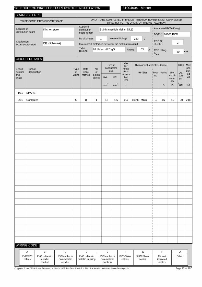
Kitchen store
DB Kitchen (A)
Sub Mains(Sub Mains, 5/L1)
88 Fuse HRC gG 63
1 230
61008 RCD
2
30
1/L1
2/L1
SPARE
Computer
-
C
-
B
-
1
-
2.5
-
1.5
-
0.4
-
60898 MCB
-
B
-
16
-
10
-
30
-
2.88
Copyright © AMTECH Power Software Ltd 1992 - 2008, FastTest Pro v9.2.1, Electrical Instullations & Appliance Testing uk ltd
TO BE COMPLETED IN EVERY CASE ONLY TO BE COMPLETED IF THE DISTRIBUTION BOARD IS NOT CONNECTED DIRECTLY TO THE ORIGIN OF THE INSTALLATION
Location of distribution board
Distribution board designation
Supply to distributionboard is from
Overcurrent protective device for the distribution circuitTypeBS(EN) Rating A
No of phases Nominal Voltage V
Associated RCD (if any)
BS(EN)
RCD No of poles
RCD rating,I
mA∆ n
Circuitnumberandphase
Circuitdesignation
Typeof
wiring
Refe-rence method
Noof
pointsserved
Circuitconductors
csa
Live cpc
mm mm2 2
Max.per-
mitteddisc-
onnec-tiontime
s
Overcurrent protective device
BS(EN) Type No
Rating Shortcircuitcapa-city
RCD
Op.curr-ent
I∆n
Max.per-mitt-edZs
Ω
PVC/PVCcables
PVC cables in metallic conduit
PVC cables in non-metallic
conduit
PVC cables in metallic trunking
PVC cables in non-metallic
trunking
PVC/SWAcables
XLPE/SWAcables
Mineralinsulatedcables
Other
31004604 - Master
A B C D E F G H O
Page 97 of 107
SCHEDULE OF CIRCUIT DETAILS FOR THE INSTALLATION
CIRCUIT DETAILS
BOARD DETAILS
WIRING CODE
kAA

0.14
1.65
39
19
07270722
07270722
07270722
07270722
N/A
1/L1
2/L1
-
N/A
-
N/A
-
N/A
-
N/A
-
0.26
-
N/A
-
>10
-
>10
-
>10
ü
-
0.42
- -
39 19
Electrical Inspection Engineer
D. Jameson
Copyright © AMTECH Power Software Ltd 1992 - 2008, FastTest Pro v9.2.1, Electrical Instullations & Appliance Testing uk ltd
ONLY TO BE COMPLETED IF THE DISTRIBUTION BOARDIS NOT CONNECTED DIRECTLY TO THE ORIGIN OF THE
INSTALLATION
Zs
Ipf kA
Ω Operating times ofassociatedRCD (if any)
5I
(if applicable)
At I ∆ n ms
ms
N/A
TEST INSTRUMENTS (SERIAL NUMBERS) USED
Earth faultloopimpedance
Insulation resistance
Continuity
RCD
Other
Other
Circuitnumberandphase
Circuit impedances
Ω
Ring final circuits only(measured end to end)
r
(Line)
r
(Neutral)
r
(cpc)
1 2n
All circuits(At least one
columnto be completed)
R + R1 2 R 2
Insulation resistance
Line/Line
Line/Neutral
Line/Earth
Earth/Neutral
Polarity
Ω Ω Ω ΩMMMM
RCD operating times
Maximummeasuredearth fault
loop impedance
Ω msms
At
I ∆ n
Signature
Name
Position
Date of testing
31004604 - Master
Page 98 of 107
n∆
At
5I∆ n
29/07/2010
SCHEDULE OF CIRCUIT TESTS FOR THE INSTALLATION
CIRCUIT TESTS
TESTED BY
BOARD TESTS
Confirmation of Supply polarity ü

Outside class D
DB 5
Sub Mains(Sub Mains, 5/L2)
88 Fuse HRC gG 63
1 230
N/A
N/A
N/A
1/L2
2/L2
3/L2
4/L2
5/L2
6/L2
7/L2
8/L2
9/L2
10/L2
11/L2
12/L2
13/L2
14/L2
15/L2
Corridor lights
Store, staircase lights
Class D lights
Class E lights
Lobby, store lights
Class F lights
Class G lights
Heaters via time clock
SPARE
SPARE
Corridor socket
Sub Mains(FDB F)
Sub Mains(FDB G)
Class room D+E sockets
SPARE
D
D
D
D
D
D
D
D
-
-
H
H
H
D
-
B
B
B
B
B
B
B
B
-
-
C
C
C
B
-
8
3
9
9
2
9
9
3
-
-
1
1
1
10
-
1.5
1.5
1.5
1.5
1.5
1.5
1.5
1.5
-
-
1.5
6
6
2.5
-
TRUNK
TRUNK
TRUNK
TRUNK
TRUNK
TRUNK
TRUNK
TRUNK
-
1.5
-
Micc
Micc
TRUNK
-
0.4
0.4
0.4
0.4
0.4
0.4
0.4
0.4
-
-
0.4
0.4
0.4
0.4
-
3871 MCB
3871 MCB
3871 MCB
3871 MCB
3871 MCB
3871 MCB
3871 MCB
3871 MCB
-
-
3871 MCB
3871 MCB
3871 MCB
61009
-
2
2
2
2
2
2
2
2
-
-
2
2
2
C
-
10
10
10
10
10
10
10
10
-
-
16
32
32
32
-
9
9
9
9
9
9
9
9
-
-
9
9
9
9
-
N/A
N/A
N/A
N/A
N/A
N/A
N/A
N/A
-
-
N/A
N/A
N/A
30
-
3.29
3.29
3.29
3.29
3.29
3.29
3.29
3.29
-
-
2.05
1.03
1.03
0.72
-
Copyright © AMTECH Power Software Ltd 1992 - 2008, FastTest Pro v9.2.1, Electrical Instullations & Appliance Testing uk ltd
TO BE COMPLETED IN EVERY CASE ONLY TO BE COMPLETED IF THE DISTRIBUTION BOARD IS NOT CONNECTED DIRECTLY TO THE ORIGIN OF THE INSTALLATION
Location of distribution board
Distribution board designation
Supply to distributionboard is from
Overcurrent protective device for the distribution circuitTypeBS(EN) Rating A
No of phases Nominal Voltage V
Associated RCD (if any)
BS(EN)
RCD No of poles
RCD rating,I
mA∆ n
Circuitnumberandphase
Circuitdesignation
Typeof
wiring
Refe-rence method
Noof
pointsserved
Circuitconductors
csa
Live cpc
mm mm2 2
Max.per-
mitteddisc-
onnec-tiontime
s
Overcurrent protective device
BS(EN) Type No
Rating Shortcircuitcapa-city
RCD
Op.curr-ent
I∆n
Max.per-mitt-edZs
Ω
PVC/PVCcables
PVC cables in metallic conduit
PVC cables in non-metallic
conduit
PVC cables in metallic trunking
PVC cables in non-metallic
trunking
PVC/SWAcables
XLPE/SWAcables
Mineralinsulatedcables
Other
31004604 - Master
A B C D E F G H O
Page 99 of 107
SCHEDULE OF CIRCUIT DETAILS FOR THE INSTALLATION
CIRCUIT DETAILS
BOARD DETAILS
WIRING CODE
kAA

0.17
1.34
N/A
N/A
07270722
07270722
07270722
07270722
N/A
1/L2
2/L2
3/L2
4/L2
5/L2
6/L2
7/L2
8/L2
9/L2
10/L2
11/L2
12/L2
13/L2
14/L2
15/L2
N/A
N/A
N/A
N/A
N/A
N/A
N/A
N/A
-
-
N/A
N/A
N/A
0.48
-
N/A
N/A
N/A
N/A
N/A
N/A
N/A
N/A
-
-
N/A
N/A
N/A
0.49
-
N/A
N/A
N/A
N/A
N/A
N/A
N/A
N/A
-
-
N/A
N/A
N/A
N/A
-
N/A
N/A
N/A
N/A
N/A
N/A
N/A
N/A
-
-
N/A
N/A
N/A
N/A
-
0.15
0.25
0.20
0.14
0.18
0.14
0.15
0.01
-
-
0.11
0.02
0.02
0.08
-
N/A
N/A
N/A
N/A
N/A
N/A
N/A
N/A
-
-
N/A
N/A
N/A
N/A
-
LIM
LIM
LIM
LIM
LIM
LIM
LIM
LIM
-
-
>10
>10
>10
>10
-
>10
>10
>10
>10
>10
>10
>10
LIM
-
-
>10
>10
>10
>10
-
>10
>10
>10
>10
>10
>10
>10
LIM
-
-
>10
>10
>10
>10
-
ü
ü
ü
ü
ü
ü
ü
ü
ü
ü
ü
ü
0.29
0.40
0.33
0.30
0.34
0.37
0.30
0.17
-
-
0.26
0.18
0.18
0.67
-
N/A N/A
N/A N/A
N/A N/A
N/A N/A
N/A N/A
N/A N/A
N/A N/A
N/A N/A
- -
- -
N/A N/A
N/A N/A
N/A N/A
30 16
- -
Electrical Inspection Engineer
D. Nichols
Copyright © AMTECH Power Software Ltd 1992 - 2008, FastTest Pro v9.2.1, Electrical Instullations & Appliance Testing uk ltd
ONLY TO BE COMPLETED IF THE DISTRIBUTION BOARDIS NOT CONNECTED DIRECTLY TO THE ORIGIN OF THE
INSTALLATION
Zs
Ipf kA
Ω Operating times ofassociatedRCD (if any)
5I
(if applicable)
At I ∆ n ms
ms
N/A
TEST INSTRUMENTS (SERIAL NUMBERS) USED
Earth faultloopimpedance
Insulation resistance
Continuity
RCD
Other
Other
Circuitnumberandphase
Circuit impedances
Ω
Ring final circuits only(measured end to end)
r
(Line)
r
(Neutral)
r
(cpc)
1 2n
All circuits(At least one
columnto be completed)
R + R1 2 R 2
Insulation resistance
Line/Line
Line/Neutral
Line/Earth
Earth/Neutral
Polarity
Ω Ω Ω ΩMMMM
RCD operating times
Maximummeasuredearth fault
loop impedance
Ω msms
At
I ∆ n
Signature
Name
Position
Date of testing
31004604 - Master
Page 100 of 107
n∆
At
5I∆ n
29/07/2010
SCHEDULE OF CIRCUIT TESTS FOR THE INSTALLATION
CIRCUIT TESTS
TESTED BY
BOARD TESTS
Confirmation of Supply polarity ü

Room F
FDB F
Sub Mains(DB 5, 12/L2)
3871 MCB 2 32
1 230
4293 RCD
2
30
1/L2
Sockets
B
B
8
2.5
COND
0.4
61009
C
32
10
30
0.72
Copyright © AMTECH Power Software Ltd 1992 - 2008, FastTest Pro v9.2.1, Electrical Instullations & Appliance Testing uk ltd
TO BE COMPLETED IN EVERY CASE ONLY TO BE COMPLETED IF THE DISTRIBUTION BOARD IS NOT CONNECTED DIRECTLY TO THE ORIGIN OF THE INSTALLATION
Location of distribution board
Distribution board designation
Supply to distributionboard is from
Overcurrent protective device for the distribution circuitTypeBS(EN) Rating A
No of phases Nominal Voltage V
Associated RCD (if any)
BS(EN)
RCD No of poles
RCD rating,I
mA∆ n
Circuitnumberandphase
Circuitdesignation
Typeof
wiring
Refe-rence method
Noof
pointsserved
Circuitconductors
csa
Live cpc
mm mm2 2
Max.per-
mitteddisc-
onnec-tiontime
s
Overcurrent protective device
BS(EN) Type No
Rating Shortcircuitcapa-city
RCD
Op.curr-ent
I∆n
Max.per-mitt-edZs
Ω
PVC/PVCcables
PVC cables in metallic conduit
PVC cables in non-metallic
conduit
PVC cables in metallic trunking
PVC cables in non-metallic
trunking
PVC/SWAcables
XLPE/SWAcables
Mineralinsulatedcables
Other
31004604 - Master
A B C D E F G H O
Page 101 of 107
SCHEDULE OF CIRCUIT DETAILS FOR THE INSTALLATION
CIRCUIT DETAILS
BOARD DETAILS
WIRING CODE
kAA

0.18
1.31
N/A
N/A
07270722
07270722
07270722
07270722
N/A
1/L2
0.80
0.81
N/A
N/A
0.25
N/A
>10
>10
>10
ü
0.65
30 8
Electrical Inspection Engineer
D. Nichols
Copyright © AMTECH Power Software Ltd 1992 - 2008, FastTest Pro v9.2.1, Electrical Instullations & Appliance Testing uk ltd
ONLY TO BE COMPLETED IF THE DISTRIBUTION BOARDIS NOT CONNECTED DIRECTLY TO THE ORIGIN OF THE
INSTALLATION
Zs
Ipf kA
Ω Operating times ofassociatedRCD (if any)
5I
(if applicable)
At I ∆ n ms
ms
N/A
TEST INSTRUMENTS (SERIAL NUMBERS) USED
Earth faultloopimpedance
Insulation resistance
Continuity
RCD
Other
Other
Circuitnumberandphase
Circuit impedances
Ω
Ring final circuits only(measured end to end)
r
(Line)
r
(Neutral)
r
(cpc)
1 2n
All circuits(At least one
columnto be completed)
R + R1 2 R 2
Insulation resistance
Line/Line
Line/Neutral
Line/Earth
Earth/Neutral
Polarity
Ω Ω Ω ΩMMMM
RCD operating times
Maximummeasuredearth fault
loop impedance
Ω msms
At
I ∆ n
Signature
Name
Position
Date of testing
31004604 - Master
Page 102 of 107
n∆
At
5I∆ n
29/07/2010
SCHEDULE OF CIRCUIT TESTS FOR THE INSTALLATION
CIRCUIT TESTS
TESTED BY
BOARD TESTS
Confirmation of Supply polarity ü

Room G
FDB G
Sub Mains(DB 5, 13/L2)
3871 MCB 2 32
1 230
4293 RCD
2
30
1/L2
Sockets
B
B
8
2.5
COND
0.4
61009
C
32
10
30
0.72
Copyright © AMTECH Power Software Ltd 1992 - 2008, FastTest Pro v9.2.1, Electrical Instullations & Appliance Testing uk ltd
TO BE COMPLETED IN EVERY CASE ONLY TO BE COMPLETED IF THE DISTRIBUTION BOARD IS NOT CONNECTED DIRECTLY TO THE ORIGIN OF THE INSTALLATION
Location of distribution board
Distribution board designation
Supply to distributionboard is from
Overcurrent protective device for the distribution circuitTypeBS(EN) Rating A
No of phases Nominal Voltage V
Associated RCD (if any)
BS(EN)
RCD No of poles
RCD rating,I
mA∆ n
Circuitnumberandphase
Circuitdesignation
Typeof
wiring
Refe-rence method
Noof
pointsserved
Circuitconductors
csa
Live cpc
mm mm2 2
Max.per-
mitteddisc-
onnec-tiontime
s
Overcurrent protective device
BS(EN) Type No
Rating Shortcircuitcapa-city
RCD
Op.curr-ent
I∆n
Max.per-mitt-edZs
Ω
PVC/PVCcables
PVC cables in metallic conduit
PVC cables in non-metallic
conduit
PVC cables in metallic trunking
PVC cables in non-metallic
trunking
PVC/SWAcables
XLPE/SWAcables
Mineralinsulatedcables
Other
31004604 - Master
A B C D E F G H O
Page 103 of 107
SCHEDULE OF CIRCUIT DETAILS FOR THE INSTALLATION
CIRCUIT DETAILS
BOARD DETAILS
WIRING CODE
kAA

0.18
1.30
N/A
N/A
07270722
07270722
07270722
07270722
N/A
1/L2
0.74
0.74
N/A
N/A
0.15
N/A
>10
>10
>10
ü
0.72
74 27
Electrical Inspection Engineer
D. Nichols
Copyright © AMTECH Power Software Ltd 1992 - 2008, FastTest Pro v9.2.1, Electrical Instullations & Appliance Testing uk ltd
ONLY TO BE COMPLETED IF THE DISTRIBUTION BOARDIS NOT CONNECTED DIRECTLY TO THE ORIGIN OF THE
INSTALLATION
Zs
Ipf kA
Ω Operating times ofassociatedRCD (if any)
5I
(if applicable)
At I ∆ n ms
ms
N/A
TEST INSTRUMENTS (SERIAL NUMBERS) USED
Earth faultloopimpedance
Insulation resistance
Continuity
RCD
Other
Other
Circuitnumberandphase
Circuit impedances
Ω
Ring final circuits only(measured end to end)
r
(Line)
r
(Neutral)
r
(cpc)
1 2n
All circuits(At least one
columnto be completed)
R + R1 2 R 2
Insulation resistance
Line/Line
Line/Neutral
Line/Earth
Earth/Neutral
Polarity
Ω Ω Ω ΩMMMM
RCD operating times
Maximummeasuredearth fault
loop impedance
Ω msms
At
I ∆ n
Signature
Name
Position
Date of testing
31004604 - Master
Page 104 of 107
n∆
At
5I∆ n
29/07/2010
SCHEDULE OF CIRCUIT TESTS FOR THE INSTALLATION
CIRCUIT TESTS
TESTED BY
BOARD TESTS
Confirmation of Supply polarity ü
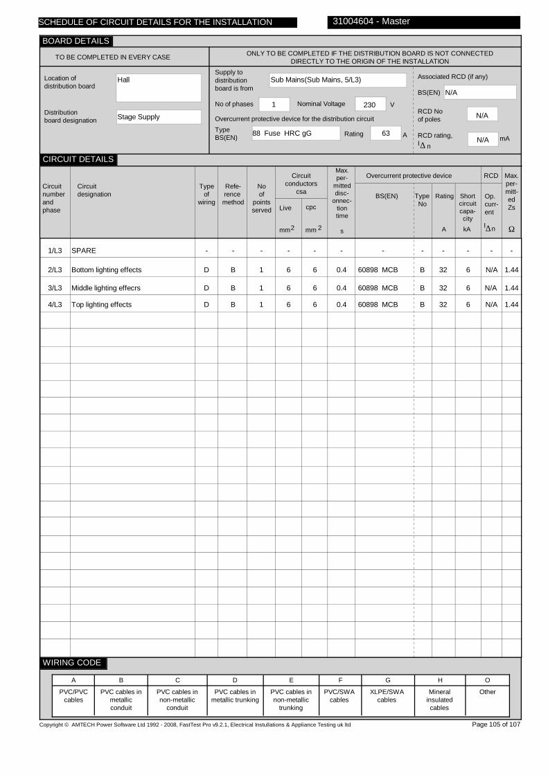
Hall
Stage Supply
Sub Mains(Sub Mains, 5/L3)
88 Fuse HRC gG 63
1 230
N/A
N/A
N/A
1/L3
2/L3
3/L3
4/L3
SPARE
Bottom lighting effects
Middle lighting effecrs
Top lighting effects
-
D
D
D
-
B
B
B
-
1
1
1
-
6
6
6
-
6
6
6
-
0.4
0.4
0.4
-
60898 MCB
60898 MCB
60898 MCB
-
B
B
B
-
32
32
32
-
6
6
6
-
N/A
N/A
N/A
-
1.44
1.44
1.44
Copyright © AMTECH Power Software Ltd 1992 - 2008, FastTest Pro v9.2.1, Electrical Instullations & Appliance Testing uk ltd
TO BE COMPLETED IN EVERY CASE ONLY TO BE COMPLETED IF THE DISTRIBUTION BOARD IS NOT CONNECTED DIRECTLY TO THE ORIGIN OF THE INSTALLATION
Location of distribution board
Distribution board designation
Supply to distributionboard is from
Overcurrent protective device for the distribution circuitTypeBS(EN) Rating A
No of phases Nominal Voltage V
Associated RCD (if any)
BS(EN)
RCD No of poles
RCD rating,I
mA∆ n
Circuitnumberandphase
Circuitdesignation
Typeof
wiring
Refe-rence method
Noof
pointsserved
Circuitconductors
csa
Live cpc
mm mm2 2
Max.per-
mitteddisc-
onnec-tiontime
s
Overcurrent protective device
BS(EN) Type No
Rating Shortcircuitcapa-city
RCD
Op.curr-ent
I∆n
Max.per-mitt-edZs
Ω
PVC/PVCcables
PVC cables in metallic conduit
PVC cables in non-metallic
conduit
PVC cables in metallic trunking
PVC cables in non-metallic
trunking
PVC/SWAcables
XLPE/SWAcables
Mineralinsulatedcables
Other
31004604 - Master
A B C D E F G H O
Page 105 of 107
SCHEDULE OF CIRCUIT DETAILS FOR THE INSTALLATION
CIRCUIT DETAILS
BOARD DETAILS
WIRING CODE
kAA

0.25
0.92
N/A
N/A
0707070985
0707070985
0707070985
0707070985
N/A
1/L3
2/L3
3/L3
4/L3
-
N/A
N/A
N/A
-
N/A
N/A
N/A
-
N/A
N/A
N/A
-
N/A
N/A
N/A
-
0.02
0.01
0.01
-
N/A
N/A
N/A
-
LIM
LIM
LIM
-
LIM
LIM
LIM
-
LIM
LIM
LIM
ü
ü
ü
-
0.30
0.26
0.26
- -
N/A N/A
N/A N/A
N/A N/A
Electrical Inspection Engineer
D. Nichols
Copyright © AMTECH Power Software Ltd 1992 - 2008, FastTest Pro v9.2.1, Electrical Instullations & Appliance Testing uk ltd
ONLY TO BE COMPLETED IF THE DISTRIBUTION BOARDIS NOT CONNECTED DIRECTLY TO THE ORIGIN OF THE
INSTALLATION
Zs
Ipf kA
Ω Operating times ofassociatedRCD (if any)
5I
(if applicable)
At I ∆ n ms
ms
N/A
TEST INSTRUMENTS (SERIAL NUMBERS) USED
Earth faultloopimpedance
Insulation resistance
Continuity
RCD
Other
Other
Circuitnumberandphase
Circuit impedances
Ω
Ring final circuits only(measured end to end)
r
(Line)
r
(Neutral)
r
(cpc)
1 2n
All circuits(At least one
columnto be completed)
R + R1 2 R 2
Insulation resistance
Line/Line
Line/Neutral
Line/Earth
Earth/Neutral
Polarity
Ω Ω Ω ΩMMMM
RCD operating times
Maximummeasuredearth fault
loop impedance
Ω msms
At
I ∆ n
Signature
Name
Position
Date of testing
31004604 - Master
Page 106 of 107
n∆
At
5I∆ n
29/07/2010
SCHEDULE OF CIRCUIT TESTS FOR THE INSTALLATION
CIRCUIT TESTS
TESTED BY
BOARD TESTS
Confirmation of Supply polarity ü

Observations and Recommendations continued from page 2
Certificate number - 31004604 - Master
Page 107 of 107
ItemNo.
Code
Code Key 1 - 'requires urgent attention' 2 - 'requires improvement' 3 - 'requires further investigation' 4 - 'does not comply with BS7671:2001 (as amended)'
16
20
21
22
23
24
25
17
18
19
26
27
28
29
30
31
32
33
34
35
At FDB Room 7, there is no Test button
At DB 3 located on the 1st flr corridor, circuit 1 serves Room 7 lighting. The light switch is damaged
At DB 3 located on the 1st flr corridor, circuit 2 serves Room 6 lighting. The light switch is missing a cover screw
At DB 3 located on the 1st flr corridor, circuit 15 could not be located. Further investigation is required to determine the equipment or area served.
At DB 4A located on the 1st flr corridor, circuit 2 serves socket outlets. The RCBO failed to operate on the '5I?n' test. Also the ring continuity for the live conductors is higher than expected. Further investigation is required.
At DB Metalwork, circuits 3TP, 4TP & 10TP could not be located. Further investigation is required to determine the equipment or area served.
At DB Metalwork, no testing was possible on circuit 11L2 as it served the Gas Guard.
DB Metalwork is positioned at high level and machines are directly below it. Access to and maintenance of this DB is difficult.
At DB 5 located outside Classroom D, circuit 7 serves Class G lighting. The light switch is damaged
At DB 1 located on the Ground flr corridor, circuit 11 could not be located. Further investigation is required to determine
At DB 5 located outside Classroom D, circuit 5 serves the lobby lighting. The light switch is missing a cover screw
At DB 6 located in the Music store, circuit 7 could not be located. Further investigation is required to determine the equipment or area served.
At DB 6 Power located in the Music store, circuit 2 could not be located. Further investigation is required to determine the equipment or area served.
At DB 7 located in the Gym Office circuit 10, no testing was possible on the Clocks due to height restrictions.
the equipment or area served. Previous description suggested 'BT Supply'.
At the sub-mains located in the main intake circuit 1TP serves the Kitchen. The 100A HRC fuse offers ineffective overcurrent protection to the installed 16mm² SWA cable
The main bonding to both Gas and Water services is by a continuous 50mm² cable
The Fire Alarm is served from the DB L&P Isolator located on the Ground floor corridor of the main block. This cannot be shown
DB Boiler House 1 is served from 3L1 of DB L&P located on the Ground floor corridor. This cannot be shown due to software
At DB 1 located on the Ground flr corridor, circuit 15 could not be located. Further investigation is required to determine the equipment or area served. Previous description suggested 'CCTV'.
At DB 2A located on the Ground flr corridor, circuit 2 serves socket outlets. The RCBO failed to operate on the '5I?n' test.
4
2
2
3
2
3
3
4
2
3
2
3
3
3
2
4
4
4
3
2
This form is based on a model developed by the NICEIC and on Appendix 6 of BS7671.© Copyright AMTECH Computer Systems Ltd. 2002
This Periodic Inspection Report form is intended for reporting on the condition of an existing electrical installation.
You should have received an original Report and the contractor should have retained a duplicate. If you were the person ordering this Report, but not the owner of the installation, you should pass this Report, or a full copy of it, immediately to the owner.
PERIODIC INSPECTION REPORTGUIDANCE NOTES FOR RECIPIENTS
These notes are based on those seen in Appendix 6 BS 7671:2008 (as amended)
Copyright © AMTECH Power Software Ltd 1992 - 2008, FastTest Pro v9.2.1, Electrical Instullations & Appliance Testing uk ltd
The 'Extent and Limitations' box should fully identify the extent of the installation covered by this Report and any limitations on the inspection and tests. The contractor should have agreed these aspects with you and any other interested parties (Licensing Authority, Insurance Company, Building Society etc) before the inspection was carried out.
For safety reasons, the electrical installation will need to be re-inspected at appropriate intervals by a competent person. The maximum time interval recommended before the next inspection is stated in the Report under 'Next Inspection.'
The original Report is to be retained in a safe place and be shown to any person inspecting or undertaking work on the electricalinstallation in the future. If you later vacate the property, this Report will provide the new owner with details of the condition of the electrical installation at the time the Report.
The report should identify any departures from the safety requirements of the current Regulations and any defects, damage or deterioration that affect. For items classified as 'required urgent attention', the safety of those using the installation may be at risk, and it is recommended that a competent person undertakes the necessary remedial work without delay.