Performance Evaluation and Utility Assessment of Magneto ... · PDF filePerformance Evaluation...
31
The author(s) shown below used Federal funds provided by the U.S. Department of Justice and prepared the following final report: Document Title: Performance Evaluation and Utility Assessment of Magneto-Optical Sensor Technology for Detecting and Visualizing Obliterated Serial Numbers in Firearms Author(s): RTI International Document No.: 245487 Date Received: March 2014 Award Number: 2011-DN-BX-K564 This report has not been published by the U.S. Department of Justice. To provide better customer service, NCJRS has made this Federally- funded grant report available electronically. Opinions or points of view expressed are those of the author(s) and do not necessarily reflect the official position or policies of the U.S. Department of Justice.
Transcript of Performance Evaluation and Utility Assessment of Magneto ... · PDF filePerformance Evaluation...

The author(s) shown below used Federal funds provided by the U.S. Department of Justice and prepared the following final report: Document Title: Performance Evaluation and Utility Assessment
of Magneto-Optical Sensor Technology for Detecting and Visualizing Obliterated Serial Numbers in Firearms
Author(s): RTI International Document No.: 245487 Date Received: March 2014 Award Number: 2011-DN-BX-K564 This report has not been published by the U.S. Department of Justice. To provide better customer service, NCJRS has made this Federally-funded grant report available electronically.
Opinions or points of view expressed are those of the author(s) and do not necessarily reflect
the official position or policies of the U.S. Department of Justice.

Performance Evaluation and Utility
Assessment of Magneto-Optical Sensor Technology for Detecting and Visualizing Obliterated Serial Numbers in Firearms
March 2014
National Institute of Justice Office of Science and Technology
Investigative and Forensic Sciences Division 810 Seventh Street, N.W. Washington, D.C. 20531
FY2011 Award #2011‐DN‐BX‐K564
This document is a research report submitted to the U.S. Department of Justice. This report has not been published by the Department. Opinions or points of view expressed are those of the author(s)
and do not necessarily reflect the official position or policies of the U.S. Department of Justice.

Performance Evaluation and Utility Assessment of Magneto‐Optical Sensor Technology for Detecting and Visualizing Obliterated Serial Numbers in Firearms
ii | P a g e
FTCOE Contact: Jeri Ropero‐Miller
FTCOC Technology Transition Task Leader [email protected]
Technical Contacts: Rudi Luyendijk, Ph.D., Principal Investigator
Midwest Forensics Resource Center, U.S. Department of Energy Ames Lab, Ames, Iowa
Firearm Examiners: Jason Butell, Johnson County Crimilsitcs Laboratory, Oalthe, Kansas
Kavin Westlan, Kansas City Police Department Crime Laboratory, Kansas City, Missouri
This document is a research report submitted to the U.S. Department of Justice. This report has not been published by the Department. Opinions or points of view expressed are those of the author(s)
and do not necessarily reflect the official position or policies of the U.S. Department of Justice.

Performance Evaluation and Utility Assessment of Magneto‐Optical Sensor Technology for Detecting and Visualizing Obliterated Serial Numbers in Firearms
iii | P a g e
Forensic Technology Center of Excellence
FTCoE is a collaborative partnership of RTI International and its FEPAC {Forensic Science Eduation Programs Accreditation Commision]‐accredited academic partmers: Duquesne University, Virginia Commonwelath University, and the University of North Texas Health Science Center. In addition to supporting NIJ’s research and development (R&D) programs, the FTCoE provides testing, and evaluation, and technology assistance to forensic laboratories and practioners in the crimal justice community. The NIJ funds the FTCoE to transition forensic science and technology to practice (Award Number 2011‐DN‐BX‐K564).
The FTCoE is led by RTI, a global research institute dedicated to improving the human condition by turning knowledge into practice. With a staff of more than 3,700 providing research and technical services to governments and businesses in more than 75 courntries, RTI brings a global perspective. The FTCoE builds on RTI’s expertise in forensic science, innovation, technology application, economics, data analytics, statistics, program evaluation, public health, and information science.
PUBLIC DOMAIN NOTICE
All material appearing in this publication is in the public domain and may be reproduced or copied without permission from the NIJ. However, this publication may not be reproduced or distributed for a fee without the specific, written authorization of the National Institute of Justice, Office of Justice Programs, U.S. Department of Justice. Citation of the source is appreciated. Suggested citation:
National Institute of Justice, Office of Justice Programs. (March 2014). Forensic Technology Center of Excellence: Performance Evaluation and Utility Assessment of Magneto‐Optical Sensor Technology for Detecting and Visualizing Obliterated Serial Numbers in Firearms.
Obtaining Copies of This Publication: Electronic copies of this publication can be downloaded from the FTCoE website at https://www.forensiccoe.org.
This document is a research report submitted to the U.S. Department of Justice. This report has not been published by the Department. Opinions or points of view expressed are those of the author(s)
and do not necessarily reflect the official position or policies of the U.S. Department of Justice.

Performance Evaluation and Utility Assessment of Magneto‐Optical Sensor Technology for Detecting and Visualizing Obliterated Serial Numbers in Firearms
NIJ FTCoE (2011‐DN‐BX‐K564) iv | P a g e
Contents
Executive Summary ....................................................................................................................................... 1
1. Introduction .......................................................................................................................................... 2
2. Magneto‐Optical (MO) Sensor Technology .......................................................................................... 3
2.1 MO Sensor Concept ...................................................................................................................... 3
2.2 MO Sensor Technology Tested ..................................................................................................... 4
2.2.1 How It Works ................................................................................................................... 5
2.2.2 Availability ....................................................................................................................... 5
3. Performance Assessment ...................................................................................................................... 5
3.1 Technical Performance Factors as Defined for this Project ......................................................... 6
3.2 Non‐Technical Performance Factors as Defined for this Project ................................................. 6
4. Experimental Design ............................................................................................................................. 6
4.1 Methodology ................................................................................................................................ 8
5. Performance Testing ............................................................................................................................. 8
6. Performance Evaluation ...................................................................................................................... 13
6.1 Magnetic Particle Inspection ...................................................................................................... 13
6.2 Comparison: MO Sensor and MPI .............................................................................................. 13
6.3 Comparison: MO Sensor and Chemical Etching ......................................................................... 15
7. Lessons Learned .................................................................................................................................. 16
7.1 Sensor Design Issues ................................................................................................................... 16
7.2 MO Sensor Selection Considerations ......................................................................................... 17
7.3 MO Sensor Technology Limitations ............................................................................................ 17
7.4 Need for Future Development and Testing ................................................................................ 17
8. Conclusions ......................................................................................................................................... 17
9. Bibliography ........................................................................................................................................ 18
Appendix A: MO Sensor Steel Serial Number Detection and Visualization ................................................ 19
Appendix B: MPI Steel Serial Number Detection and Visualization ........................................................... 20
Appendix C: Chemical Etching Steel Serial Number Detection and Visualization ...................................... 21
Appendix D: Chemical Etching Other Substrate Serial Number Detection and Visualization .................... 22
Appendix E: Derivation of MO vs MPI Contingency Table Values .............................................................. 23
Appendix F: Derivation of MO vs Chemical Etching Contingency Table Values ......................................... 24
This document is a research report submitted to the U.S. Department of Justice. This report has not been published by the Department. Opinions or points of view expressed are those of the author(s)
and do not necessarily reflect the official position or policies of the U.S. Department of Justice.

Performance Evaluation and Utility Assessment of Magneto‐Optical Sensor Technology for Detecting and Visualizing Obliterated Serial Numbers in Firearms
NIJ FTCoE (2011‐DN‐BX‐K564) v | P a g e
ListofTables
1. Type A MO sensor properties. ............................................................................................ 4 2. Experimental setup for MO sensor technology performance testing. ............................... 7 3. MO sensor technology performance testing results. ......................................................... 9 4. MO sensor accuracy ............................................................................................................ 9 5. MO sensor reproducibility. ............................................................................................... 10 6. MO sensor recovery. ......................................................................................................... 10 7. MO sensor selectivity. ....................................................................................................... 10 8. MO sensor sample preparation. ....................................................................................... 11 9. MO sensor system operation. ........................................................................................... 11 10. MO sensor technology sample processing measurement times. .................................... 12 11. MO sensor cost. ................................................................................................................ 12 12. MO sensor worker safety. ................................................................................................. 12 13. Contingency for comparing MO sensor technology performance results. ...................... 13 14. Comparison of non‐technical performance characteristics for MO sensor
technology and MPI technology. ...................................................................................... 14 15. Comparison of non‐technical performance characteristics for MO sensor
technology and chemical etching. .................................................................................... 16
ListofFigures
1. 45 automatic Colt with obliterated serial number on the frame. ........................................ 2 2. MO sensor configuration showing the four functional layers. ............................................. 3 3. Rotation angle differences caused by the magnetic field’s poles of the magnetic
material. ................................................................................................................................ 4 4. CMOS Magview with O‐ring placed on the MO sensor (source: Matesy GmbH). ............... 4 5. Type A MO sensor hysteresis curve. ..................................................................................... 5 6. Visualized obliterated serial number on steel substrate. ..................................................... 5 7. Open back, inclinable press used for stamping serial numbers. .......................................... 8
This document is a research report submitted to the U.S. Department of Justice. This report has not been published by the Department. Opinions or points of view expressed are those of the author(s)
and do not necessarily reflect the official position or policies of the U.S. Department of Justice.

Performance Evaluation and Utility Assessment of Magneto‐Optical Sensor Technology for Detecting and Visualizing Obliterated Serial Numbers in Firearms
NIJ FTCoE (2011‐DN‐BX‐K564) vi | P a g e
The information shared in this report represents the opinions of the individual practitioners and researchers who participated in the technology testing and evaluation, and not the opinions of their agencies, the FTCoE, or the NIJ. In addition, the individual agents were not part of the agency’s technology selection process and have not participated in this project to endorse or protest any technology. Finally, no individual involved in the testing and evaluation process received any financial or materials support from the manufacturers of the equipment. For more information or questions about this report, visit www.forensiccoe.org, e‐mail Forensic COE [email protected] or call 1‐866‐252‐8415.
This document is a research report submitted to the U.S. Department of Justice. This report has not been published by the Department. Opinions or points of view expressed are those of the author(s)
and do not necessarily reflect the official position or policies of the U.S. Department of Justice.

Performance Evaluation and Utility Assessment of Magneto‐Optical Sensor Technology for Detecting and Visualizing Obliterated Serial Numbers in Firearms
NIJ FTCoE (2011‐DN‐BX‐K564) 1 | P a g e
EXECUTIVE SUMMARY
In the United States, firearms manufactured after 1968 must contain a serial number somewhere on the metal frame. Each number is unique and typically stamped into the metal. During the stamping process, the crystalline structure of the metal is deformed and compacted below the identification number. When criminals destroy the serial number (using a variety of filing, grinding, and peening techniques) to avoid tracing of the firearm to its owner, the serial number may not be visible to the naked eye, but may still be recoverable. Recovery of the obliterated serial number greatly depends on the material used in the manufacturing of the firearm and on the depth of the obliteration.
Over the years, a number of techniques have been developed to detect and restore obliterated serial numbers in firearms. Current techniques fall into one of two categories: destructive and non‐destructive. In destructive methods, the most commonly used technique is chemical etching. Restoration by this technique requires extensive sample preparation, the appropriate selection of etchants, and extreme care during etching of the specimen. In non‐destructive methods, such as magnetic particle inspection (MPI), the original state of the specimen is preserved. Because of this preservation of material, non‐destructive methods are generally preferred by examiners. However, non‐destructive methods are extremely messy and suffer from low sensitivity.
The discovery of more effective methods to detect and restore erased markings in firearms, consequently, is of great interest to firearm examiners, in particular the invention of new non‐destructive methods. Magneto optical (MO) sensor technology may address this need. The technology was initially developed for the medical engineering field and was recently adapted for use in forensics. The sensor’s operating principle is the Faraday‐effect, which allows for the real‐time visualization and analysis of the magnetic distribution of sample materials. The technology is manufactured by Matesy GmbH and is commercially available in the United States through Absolute Magnetic Measurements & Solutions, St. Petersburg, FL.
In this project, MO sensor technology was evaluated for the detection and visualization of obliterated serial numbers in five different metals and one composite material. All materials tested are currently used by firearm manufacturers. Technical performance factors included MO sensor sensitivity (detection limit), accuracy, reproducibility, recovery, and selectivity. Non‐technical performance factors included sample preparation, system operation, sample processing, worker safety, and cost. The evaluation found that the MO sensor technology is a valid and reliable method for obliterated serial number identification in ferromagnetic materials. The technology requires little to no sample preparation, is easy to use, and allows for the identification of obliterated serial numbers in seconds, with time increasing to minutes at lower detection limits. When compared to the two gold standards in serial number restoration (chemical etching and MPI), MO sensor technology outperforms both in performance, as well as in utility, on the samples tested.
The sensor technology’s limitation is its configuration. For the MO technology to work effectively, the sensor must be in direct contact with the sample. Because of this, the MO sensor technology in its current configuration can only be used on planar surfaces. While this restriction greatly limits the detection and restoration of obliterated serial numbers in firearms, it may not limit the detection and deciphering of alterations in documents using magnetic ink, or the development and visualization of fingerprints using magnetic powder. It is recommended that application of the MO sensor technology in its current configuration be tested and evaluated in questioned document and latent print examinations.
This document is a research report submitted to the U.S. Department of Justice. This report has not been published by the Department. Opinions or points of view expressed are those of the author(s)
and do not necessarily reflect the official position or policies of the U.S. Department of Justice.

Performance Evaluation and Utility Assessment of Magneto‐Optical Sensor Technology for Detecting and Visualizing Obliterated Serial Numbers in Firearms
NIJ FTCoE (2011‐DN‐BX‐K564) 2 | P a g e
It is also recommended that a different MO sensor system approach be evaluated for the restoration of obliterated serial numbers in firearms. In particular, placement of the MO sensor film directly onto the sample and evaluation of that approach on realistic obliterated firearm serial numbers is recommended. Given the MO sensor technology’s high sensitivity, fast response, and ease of use, the technology, if successful, could replace MPI as a standard in the non‐destructive restoration of obliterated serial numbers.
The finding of chemical etching being potentially useful for the restoration of erased markings in Nylon 6 (polyester) was surprising and offers perspective for the future.
1. INTRODUCTION
The Gun Control Act of 1968 requires that all newly manufactured firearms produced and imported in the United States bear a serial number. The number must be placed on the frame, receiver, or barrel and contain a sequence of letters and/or numbers that uniquely identify the firearm. The number must be engraved, cast, or stamped on the firearm in print size no smaller than 1/16 inch and to a minimum depth of 0.003 inch. Stamping and laser etching are the two most commonly used serial number impression methods.
When a die stamps a piece of metal, the crystalline structure of the metal is deformed and compacted a short distance beneath the identification number. Two deformation zones result from the stamping process: plastic and elastic. The plastic deformation zone is permanent, while the elastic zone is not. If the zone of plastic deformation is still present after a serial number alteration or obliteration, it is possible to restore the serial number. Recovery of an obliterated serial number (Figure 1, see orange box) greatly depends on the material used in the manufacturing of the firearm and the depth of the obliteration.
Figure 1. 45 automatic Colt with obliterated serial number on the frame.
Over the years, a number of techniques have been developed and implemented to detect and restore obliterated serial numbers on firearms (Klees, 2008). These techniques fall into two general categories: destructive and non‐destructive. In destructive methods, the most commonly used
This document is a research report submitted to the U.S. Department of Justice. This report has not been published by the Department. Opinions or points of view expressed are those of the author(s)
and do not necessarily reflect the official position or policies of the U.S. Department of Justice.

Performance Evaluation and Utility Assessment of Magneto‐Optical Sensor Technology for Detecting and Visualizing Obliterated Serial Numbers in Firearms
NIJ FTCoE (2011‐DN‐BX‐K564) 3 | P a g e
technique is chemical etching, which applies a mixture of acid‐based chemicals directly to the area where the obliteration occurred. As chemicals can destroy the samples, and subsequently the evidence, the examination can take place only once and typically not a second time, so extreme care must be taken to document the procedures and results.
In non‐destructive methods, the original state of the specimen is maintained and preserved, allowing for the examination of the specimen more than once. The most commonly used non‐destructive technique is magnetic particle inspection (MPI). This method applies a mixture of metal flakes and light oil to the obliterated area. The metal flakes provide a shadow of each number and letter that made up the origi‐nal serial number, allowing the firearm examiner to view and document the results. As non‐destructive methods do not damage the evidence, they are typically applied before the use of a destructive method. If the serial number cannot be restored with a method like MPI, a different technique is applied, oftentimes chemical etching.
2. MAGNETO-OPTICAL (MO) SENSOR TECHNOLOGY
Magneto‐optical (MO) sensor technology is a new and innovative mapping technique for magnetic field analysis and visualization. The technology was developed by Innovent (a non‐profit, private research association) and is manufactured by Matesy GmbH in Jena, Germany. Using a bismuth‐substituted rare earth iron garnet compound, Innovent created a ferromagnetic layer with excellent MO imaging properties. The mono‐crystalline sensor MO film is coated with additional mirror and protective layers during the manufacturing process. High‐resolution MO sensors are created in customized shapes and sizes based on 1‐ and 3‐inch diameter wafers (Figure 2).
Figure 2. MO sensor configuration showing the four functional layers.
2.1 MO Sensor Concept
The concept of MO sensors is based on the Faraday effect, which states that the polarization of light waves is rotated with the propagation of the light along (or opposite to) a magnetic field inside some material (Koschny and Lindner, 2012). This rotation depends on the Verdet constant, which is a property of the material, as well as the strength of the magnetic field and the optical path. When light passes the MO medium, the polarization of the light is rotated if there is a magnetic field in the material. The angle of rotation depends on the local magnetic field strength and results in contrast differences that can be visualized in real time (Figure 3).
Substrate
MO layer
Mirror
Protection
This document is a research report submitted to the U.S. Department of Justice. This report has not been published by the Department. Opinions or points of view expressed are those of the author(s)
and do not necessarily reflect the official position or policies of the U.S. Department of Justice.

Performance Evaluation and Utility Assessment of Magneto‐Optical Sensor Technology for Detecting and Visualizing Obliterated Serial Numbers in Firearms
NIJ FTCoE (2011‐DN‐BX‐K564) 4 | P a g e
Figure 3. Rotation angle differences caused by the magnetic field’s poles of the magnetic material. S and N denote the south to north
orientation of the sample (source: Matesy GmbH).
2.2 MO Sensor Technology Tested
This project tested and evaluated the CMOS‐Magview system (Figure 4) developed by Innovent and manufactured by Matesy GmbH for the detection and visualization of obliterated serial numbers on firearms (Koschny et al., 2011). The CMOS‐Magview is a digital MO readout system consisting of magneto‐optical imaging films (MOIF), a light source, and a high‐resolution camera, all located within a non‐magnetic case. Physical dimensions of the CMOS‐Magview are 9.06x5.91x2.36 inch (LxWxH) or 230x150x60 mm.
Figure 4. CMOS Magview with O-ring placed on the MO sensor (source: Matesy GmbH).
Table 1. Type A MO sensor properties.
Faraday Rotation ~ 4°/ (kA/m)
Magnetic Range 0.01 to 2 kA/m
Optical Resolution 10 to 25 µm/pixel
Transmission Range (VIS) λ > 530 nm
Sensor Size Ø ≤ 70 mm
Sensor Thickness 0.5 mm
Polarization plane of reflected light beam
Polarization plane of incident light beam
This document is a research report submitted to the U.S. Department of Justice. This report has not been published by the Department. Opinions or points of view expressed are those of the author(s)
and do not necessarily reflect the official position or policies of the U.S. Department of Justice.

Performance Evaluation and Utility Assessment of Magneto‐Optical Sensor Technology for Detecting and Visualizing Obliterated Serial Numbers in Firearms
NIJ FTCoE (2011‐DN‐BX‐K564) 5 | P a g e
The system is operated by the CMOS‐Magview software and is connected via USB interface to an IBM‐compatible PC. The software is capable of saving images as JPG, BMP, or data‐CSV files. Visualization of the stray fields is achieved through an MO sensor. In this project, the Type A sensor (Table 1) was used because, at the time of use, it was the most sensitive MO sensor (Figure 5) manufactured by Matesy.
Figure 5. Type A MO sensor hysteresis curve.
2.2.1 How It Works
The MO sensor works by passing polarized light from a light source under influence of an external magnetic field. The light is reflected by the mirror layer after crossing the MO active film. An analyzer eliminates all non‐altered components of the mirrored light beam. The result is a colored image of all magnetic fields over the sensor area. The formed image contrast depends on the local strength and direction of the magnetic field. The sensor transforms one field direction to a bright intensity and reversely to a dark intensity. A camera records this image with a five (5) megapixel resolution (Figure 6).
2.2.2 Availability
The CMOS‐Magview system is commercially available in the United States through Absolute Magnetic Measurements & Solutions LLC (AMMS), located in St. Petersburg, Florida (AMMS, 1601 11th Street North, St. Petersburg, FL 33704, Attn: Marco Koschny). The system can be customized through the use of different MO sensors.
3. PERFORMANCE ASSESSMENT
For performance testing and evaluation, the project tested the capability and utility of the MO sensor at the Johnson County Sheriff’s Office Criminalistics Laboratory in Olathe, Kansas. A total of 10
Figure 6. Visualized obliterated serial number on steel
substrate.
This document is a research report submitted to the U.S. Department of Justice. This report has not been published by the Department. Opinions or points of view expressed are those of the author(s)
and do not necessarily reflect the official position or policies of the U.S. Department of Justice.

Performance Evaluation and Utility Assessment of Magneto‐Optical Sensor Technology for Detecting and Visualizing Obliterated Serial Numbers in Firearms
NIJ FTCoE (2011‐DN‐BX‐K564) 6 | P a g e
different performance factors were examined, representing both technical and non‐technical characteristics. Testing followed the criteria identified by the SWGs (e.g., SWGFAST), as well as elements of the National Institute of Standards and Technology (NIST)‐developed System, Component, and Operationally Relevant Evaluations (SCORE) framework for the evaluation of emerging technologies.
Technical performance factors included MO sensor sensitivity (detection limit), accuracy, reproducibility, recovery, and selectivity. Non‐technical performance factors included sample preparation, system operation, sample processing, worker safety, and cost. Collectively, these factors present an extensive picture of how the MO sensor will behave in a realistic crime laboratory firearm examination environment. The following provides a list of the performance factors tested and their definition for the purpose of this report.
3.1 Technical Performance Factors as Defined for this Project
The technical performance factors for this project were as follows:
Sensitivity – Ability to detect and visualize the presence of an obliterated serial number or serial number character. In this project, sensitivity is synonymous with limit of detection (LOD).
Accuracy – Degree to which the sensor technology produces serial number detection and visualization results consistent with actual values of the obliterated serial number.
Reproducibility – Degree of consistency between the two firearm examiners to provide the same results for a given sample over a short period of time, using the same method and the same equipment in the same laboratory.
Recovery – Percentage of obliterated serial numbers that can be visualized within the MO sensor technology LOD.
Selectivity – Ability to detect and differentiate the obliterated serial number in the presence of sensor image and sample substrate interferences.
3.2 Non-Technical Performance Factors as Defined for this Project
The non‐technical performance factors for this project were as follows:
Sample Preparation – Steps or processes the sample must undergo prior to using the MO sensor restoration technique.
System Operation – Skills required to operate the MO sensor technology and to satisfactorily execute the analytical process.
Sample Processing – Time from start to finish of the analytical process to detect and visualize the obliterated serial number.
Worker Safety – Degree to which firearm examiners using the MO sensor technology are exposed to risk of injury or long‐term toxicity associated with sample preparation and analysis.
Sensor Technology Cost – Economics associated with sample analysis, including direct costs but excluding indirect costs.
4. EXPERIMENTAL DESIGN
The goals of this project were three‐fold. The primary goal was to assess the technical capabilities of the MO sensor technology so as to determine the potential application to firearm obliterated serial number restoration. A secondary goal was to assess the utility of the technology for
This document is a research report submitted to the U.S. Department of Justice. This report has not been published by the Department. Opinions or points of view expressed are those of the author(s)
and do not necessarily reflect the official position or policies of the U.S. Department of Justice.

Performance Evaluation and Utility Assessment of Magneto‐Optical Sensor Technology for Detecting and Visualizing Obliterated Serial Numbers in Firearms
NIJ FTCoE (2011‐DN‐BX‐K564) 7 | P a g e
use by forensic firearm examiners. A third goal was to evaluate the results obtained and to compare them to the findings for the same samples using the current gold standards for restoring firearm markings: chemical etching ( a destructive technique) and MPI (a non‐destructive method).
Two different crime laboratories participated in the project: the Johnson County Sheriff’s Office Criminalistics Laboratory (JoCo) and the Kansas City Police Department’s Crime Laboratory (KCPD). Each laboratory volunteered one forensic firearm examiner. Both examiners have over 10 years of experience in restoring obliterated serial numbers; have worked together in the past utilizing the same standard operating procedures (SOPs); and are active members of the Association of Firearm and Tool Mark Examiners (AFTE).
Six different substrates were selected for testing: five metals and polyester. The metals selected were obtained from Precision Forensic Testing (Dayton, Ohio) and consisted of stainless steel, hot rolled steel, heat treated steel, zinc, and aluminum. Nylon was selected to represent polyester. All materials are currently used by firearm manufacturers. Polyester was examined because the material is increasingly being used by firearm manufacturers to reduce the firearm’s weight. Although currently, no serial numbers are stamped directly into the polyester substrate, the material was included should the need for polyester‐stamped serial number restoration arise in the future. Table 2 presents the experimental setup for MO sensor technology performance testing.
Precision Forensic Testing (PFT) was selected to stamp the serial numbers onto the stock material and to remove the serial numbers in steps of 0.003 inch. These substrate removal depths were chosen based on preliminary detection data obtained for stainless steel by the MO sensor technology. PFT was selected to perform the stamping and milling of the serial numbers because the company uses the same equipment as the firearm industry to stamp serial numbers and provides proficiency test samples to the forensic community for the restoration of obliterated serial numbers.
Table 2. Experimental setup for MO sensor technology performance testing.
304 Stainless Steel
1018 Hot Rolled Steel
4140 Heat Treated Steel 7075 Aluminum Zinc
Nylon 6 (Polyester)
Substrate Removal D
epth
(inches)
0.003 0.003 0.003 0.003 0.003 0.003
0.006 0.006 0.008 0.006 0.006 0.006
0.009 0.009 0.011 0.009 0.009 0.009
0.012 0.012 0.012 0.012 0.012 0.012
0.015 0.015 0.015 0.015 0.015 0.015
0.018 0.018 0.018 0.018 0.018 0.018
0.021 0.021 0.021 0.021 0.021 0.021
0.024 0.024 0.024 0.024 0.024
0.027 0.027 0.027 0.027 0.027
0.030 0.030 0.030
This document is a research report submitted to the U.S. Department of Justice. This report has not been published by the Department. Opinions or points of view expressed are those of the author(s)
and do not necessarily reflect the official position or policies of the U.S. Department of Justice.

Performance Evaluation and Utility Assessment of Magneto‐Optical Sensor Technology for Detecting and Visualizing Obliterated Serial Numbers in Firearms
NIJ FTCoE (2011‐DN‐BX‐K564) 8 | P a g e
4.1 Methodology
Samples were made on 0.250‐inch stock material. A random combination of six alpha‐numeric characters from Monode Marking System was stamped onto the substrates using an eight‐ton, Open Back Inclinable press (Figure 7). Serial numbers were removed using a Bridgeport Series 2 vertical mill with a 1‐inch carbide‐end mill, in one pass until no visible marks were present. At that point, a measurement of the plate thickness was taken. The difference between the original plate thickness and its thickness at the point where the serial number was no longer visible indicated the stamp depth. The stamp depth was determined to be 0.010 inch for the three steels, 0.013 inch for aluminum and polyester, and 0.019 inch for zinc.
Once the stamp depths were determined, additional substrate material was removed in intervals of 0.003 inch. At each interval, the sample was placed on a surface plate for measurement. The surface plate was calibrated using certified gauge blocks at 0.100" and 0.200". Measurements were taken by subtracting the thickness of the sample where the material was removed from the original thickness of the material. Once the targeted depth was reached, it was recorded on the rear left corner of the sample, along with a letter code for the substrate (e.g., SS 304 0.027 represented a Stainless Steel 304 sample with 0.027 inch obliteration depth). The final step was the removal of the side areas of the sample to provide a raised area for the obliterated serial number to make contact with the MO sensor.
Samples were organized according to substrate and in order of the amount of material removed during milling. Samples were then inspected to see if polishing was needed, and those requiring polishing were polished with a mild abrasive compound using the Dremel attachment (cloth wheel). Each sample was then placed on the MO sensor, starting with one type of substrate and moving up in obliteration depth. The process clock started as soon as the samples were placed on the sensor and oriented right‐side up. The process clock stopped when all legible characters were detected and visualized. At that time, the image was captured using the CMOS software; flipped in Microsoft Paint to account for the backwards orientation of the characters by the software; labeled; and saved. If no characters could be detected and visualized, no image was captured, and the sample stayed on the MO sensor only long enough to search the area utilizing magnetic fields manually.
5. PERFORMANCE TESTING
Based on the project objectives, the following performance characteristics were assessed: sensor sensitivity, accuracy, reproducibility, recovery, selectivity, sample preparation, system operation, sample processing, worker safety, and cost. These are discussed below.
Sensitivity: The primary sensitivity assessment for this project was the sensor’s LOD. For this project, the LOD is defined as the depth of obliteration below the stamping depth when the sensor is no longer capable of detecting and clearly visualizing one of the characters or numbers in the serial number. Values below the LOD were not considered for sensitivity analysis as they cannot be discerned with certainty from background noise. Taking the best detection and visualization results for each substrate, the LOD for 304 Stainless Steel was 0.024 inch, or 0.061 mm; for 1018 Hot‐Rolled Steel, the
Figure 7. Open back, inclinable press used for stamping
serial numbers.
This document is a research report submitted to the U.S. Department of Justice. This report has not been published by the Department. Opinions or points of view expressed are those of the author(s)
and do not necessarily reflect the official position or policies of the U.S. Department of Justice.

Performance Evaluation and Utility Assessment of Magneto‐Optical Sensor Technology for Detecting and Visualizing Obliterated Serial Numbers in Firearms
NIJ FTCoE (2011‐DN‐BX‐K564) 9 | P a g e
LOD was 0.012 inch, or 0.030 mm; and for 4140 Heat‐Treated Steel, the LOD wass also 0.024 inch, or 0.061 mm. LOD assessments were limited to the three steel substrates, as only these yielded results with the MO sensor. The term “no detection” means that no characters could be visualized, while the term “not discernible” indicates that characters could still be detected but not not chearly visualized (i.e., determined).
Table 3. MO sensor technology performance testing results.
Substrate Material 304 Stainless Steel 1018 Hot Rolled Steel 4140 Heat Treated Steel
Obliteration Depth Examiner 1 Examiner 2 Examiner 1 Examiner 2 Examiner 1 Examiner 2
0.003 inch C28NKF C28NKF KYT312 ?????? KYT312 KYT312
0.006 inch C28NKF C28NKF KYT312 KYT3?? KYT312 KYT312
0.009 inch C28NKF C28NKF KY???? Not discernible
KYT312 KYT312
0.012 inch C28NKF C28NKF ?Y???? Not discernible
KYT312 KYT312
0.015 inch C28NKF C28NKF Not discernible
Not discernible
KYT312 KYT?1?
0.018 inch C2/S8NKF C?8NKF No detection No detection KYT31? KYT312
0.021 inch C2??K? C??NKF No detection No detection K/X??3?? KYT???
0.024 inch C????F No detection No detection No detection K/XY??2 Not discernible
0.027 inch No Detection
No detection No detection No detection Not Discernible
Not discernible
0.030 inch No Detection
No detection No detection No detection Not Discernible
No detection
Accuracy: The MO sensor technology’s accuracy was assessed from the sensor’s capability to extract the same serial number character as the one stamped into the substrate. In this project, accuracy is represented as an approximation error, i.e., the discrepancy between an exact (true) value and some approximation to it. A relative percent error was calculated, which is the absolute error (i.e., the number of difficult to discern characters) divided by the magnitude of the exact value (i.e., the total number of discernible characters). Utilizing this formula, the relative error percent for the MO sensor for 304 Stainless Steel was 1.27% (1/79), for 1018 Hot Rolled Steel was 0.00% (0/19), and for 4140 Heat Treated Steel was 1.33% (1/75). As accuracy is the reverse of error, the accuracy for 304 Stainless Steel was 98.73%; for 1018 Hot Rolled Steel was 100%; and for 4140 Heat Treated Steel was 98.67% (Table 4).
Table 4. MO sensor accuracy
304 Stainless Steel 1018 Hot Rolled Steel 4140 Heat Treated Steel
Accuracy 98.73% 100% 98.67%
Reproducibility: The reproducibility of the MO sensor technology was assessed to determine the consistency of the technology. This was achieved by conducting an inter‐firearm examiner study involving the two firearm examiners who participated in the sensor performance test over a 2‐week period of time using the same sets of sample examination results. The degree to which the two firearm examiners (examining the same sample) agree on detection and visualization of the obliterated serial
This document is a research report submitted to the U.S. Department of Justice. This report has not been published by the Department. Opinions or points of view expressed are those of the author(s)
and do not necessarily reflect the official position or policies of the U.S. Department of Justice.

Performance Evaluation and Utility Assessment of Magneto‐Optical Sensor Technology for Detecting and Visualizing Obliterated Serial Numbers in Firearms
NIJ FTCoE (2011‐DN‐BX‐K564) 10 | P a g e
number within the sensor’s LOD is indicative of whether the same samples produce the same result. To determine the degree of agreement, the Kappa statistic was computed:
K = P(A) P(E)
1 P(E)
where P(A) is the proportion of times the two firearm examiners agree, and P(E) is the proportion of times the two examiners are expected to agree by chance alone. Complete agreement corresponds to K = 1 , and lack of agreement (i.e., purely random coincidences of rates) corresponds to K = 0 . Using the data displayed in Table 3, the Kappa statistic was computed to be: (0.78 – 0.61) : (1‐ 0.61) = 0.44.
According to Sim and Wright (2005), the calculated K statistic of 0.44 denotes “moderate” agreement between the two fireatm examiners (i.e., the range is from poor [<0.0] to almost perfect [0.81‐1.00]), indicating that reproducibility is also “moderate” (Table 5).
Table 5. MO sensor reproducibility.
Strength of Agreement
Reproducibility Moderate
Recovery: The effectiveness of the MO sensor was assessed from the recovery of visible characters within the sensor’s LOD. In this project, recovery was not concerned with conformity to trueness, but focused on detecting visible characters and can be computed as a Recovery Factor by dividing the number of detected visible characters by the total number of characters stamped within the LOD x 100%. As shown in the table below, for 304 Stainless Steel, the MO sensor’s Recovery Factor was 87.78%; for 1018 Hot Rolled Steel, 52.78%; and for 4140 Heat Treated Steel, 85.56% (Table 6).
Table 6. MO sensor recovery.
304 SS 1018 HRS 4140 HTS
Recovery Factor 87.78% 52.78% 85.56%
Selectivity: The MO sensor’s selectivity was assessed qualitatively from the different types of material used to test the MO sensor technology’s performance. The three steels (i.e., 304 Stainless, 1018 Hot Rolled, and 4140 Heat Treated) yielded results. The two other metals (aluminum and zinc), and polyester (Nylon 6) did not (Table 7). The reason for this finding is that the operating principle of the MO sensor (Faraday‐effect) requires magnetic permeability of the sample material. The three steels exhibited magnetic permeability in one form or another, the three other materials did not (Table 7).
Table 7. MO sensor selectivity.
304 SS 1018 HRS 4140 HTS Aluminum Zinc Nylon 6
Selectivity Yes Yes Yes No No No
Sample Preparation: The extensiveness and effort involved in preparing each sample for testing by the MO sensor technology was assessed to determine the sample preparation performance characteristic. Three criteria were qualitatively assessed: polishing, system mobilization, and use of chemicals. This effort was found that, unless surfaces are rough, no sample polishing was required. It
This document is a research report submitted to the U.S. Department of Justice. This report has not been published by the Department. Opinions or points of view expressed are those of the author(s)
and do not necessarily reflect the official position or policies of the U.S. Department of Justice.

Performance Evaluation and Utility Assessment of Magneto‐Optical Sensor Technology for Detecting and Visualizing Obliterated Serial Numbers in Firearms
NIJ FTCoE (2011‐DN‐BX‐K564) 11 | P a g e
also found that no other sample preparation was necessary (Table 8). In most cases, samples could be placed directly onto the sensor without any preparation.
Table 8. MO sensor sample preparation.
304 SS 1018 HRS 4140 HTS Aluminum Zinc Nylon 6
Sample Preparation No No No No No No
System Operation: Two different criteria were assessed to determine the system operation performance characteristic: user friendliness and ease of use (Table 9). To assess user friendliness, the effort involved in obtaining useable results was determined, while the required skillset of the firearm examiners was determined to assess MO sensor technology ease of use. It was found that some effort is involved in sample orientation on the viewing screen. Placement of directional arrows on the sensor case is necessary to figure out which side was “up” versus “down” and “left” versus “right” on the monitor. Another complication occurred because the viewing screen had the characters in reverse. Once these problems were solved, system operation was drastically more user friendly. It was also found that the skillset required to operate the MO sensor system is low. One of the firearm examiners received a 2‐hour on‐site training from the manufacturer on system set‐up and operation. The other firearm examiner was instructed by the first firearm examiner during a 10‐minute training session on the same items. Little disagreement was found between the results of the two examiners.
Table 9. MO sensor system operation.
User Friendliness Ease of Use
System Operation Set up required time Simple
Sample Processing: The assessment of the sample processing performance characteristic required the evaluation of measurement time, i.e., the time involved between placing and removing the sample from the MO sensor case. It was found that for the 304 Stainless Steel and the 4140 Heat Treated Steel, the measurement time initially was in seconds, increasing to several minutes at the lower end of the sensor’s LOD (Table 10). For the 1018 Hot Rolled Steel, the measurement time was always in minutes, increasing from around 6 minutes initially to around 7.5 minutes at the lower detection limit. This could suggest that the sensor has difficulty detecting and visualizing serial number characters in a low carbon steel with a higher manganese content than other general‐purpose steels. It was also found that there was a noticeable difference in sample processing time between Examiner 1 ( x̄ = 6.29 min; SD 4.11 min) and Examiner 2 (x̄ = 1.12 minutes; SD 0.73 min). This difference in measument appears to be more related to examiner attributes than to familiarity with the CMOS‐Magview system, as Examiner 1 received the the training from the manufacturer, and Examiner 2 was trained by Examiner 1.
This document is a research report submitted to the U.S. Department of Justice. This report has not been published by the Department. Opinions or points of view expressed are those of the author(s)
and do not necessarily reflect the official position or policies of the U.S. Department of Justice.

Performance Evaluation and Utility Assessment of Magneto‐Optical Sensor Technology for Detecting and Visualizing Obliterated Serial Numbers in Firearms
NIJ FTCoE (2011‐DN‐BX‐K564) 12 | P a g e
Table 10. MO sensor technology sample processing measurement times.
Substrate 304 Stainless Steel 1018 Hot Rolled Steel 4140 Heat Treated Steel
Obliteration Depth Recovery
Measurement Time
(average) Recovery
(Ex1)
Measurement Time
(average) Recovery
(Ex1)
Measurement Time
(average)
0.003 inch C28NKF 0.37 min KYT312 6.00 min KYT312 0.20 min
0.006 inch C28NKF 0.37 min KYT312 6.00 min KYT312 0.37 min
0.009 inch C28NKF 0.37 min KY???? 7.50 min KYT312 1.75 min
0.012 inch C28NKF 1.75 min ?Y???? 7.50 min KYT312 2.00 min
0.015 inch C28NKF 1.75 min Not discernible
7.50 min KYT312 3.50 min
0.018 inch C2/S8NKF 3.12 min No detection KYT31? 5.37 min
0.021 inch C2??K? 4.00 min No detection K/X??3?? 5.38 min
0.024 inch C????F 5.00 min No detection K/XY??2 6.00 min
0.027 inch No detection
No detection Not Discernible
6.00 min
0.030 inch No detection
No detection Not Discernible
6.00 min
Cost: For the assessment of cost, two different costs are determined: CMOS system capital cost and MO sensor replacement cost. As shown in the table below, the capital cost for the CMOS system is currently around $ 15,000. Although the initial investment cost is high, maintenance costs for the system are low because the system has very few moveable parts. In addition, both training and the software to operate the CMOS system are included in the purchase price, as are upgrades to the software. Sensor replacement cost is around $2,200 (Table 11). Given the limited durability of the current sensor’s protective coating, this can be problematic. Economics of scale, a better protective sensor coating, and possible application and use of the sensor technology in other forensic disciplines (e.g., questioned documents and latent print) may make acquisition of the technology possible, especially at larger crime laboratories, or at crime laboratories examining large numbers of firearm and tool mark erased markings.
Table 11. MO sensor cost.
CMOS System Cost MO Sensor Cost
Capital Costs $15,000 $2,200
Worker safety: As part of the performance assessment, the potential for health and safety concerns was determined. As shown in Table 12, one concern was noted during performance testing of the MO sensor technology. Exposure to the sharp and raised edges of the various samples examined was the only health and safety concern. No solvents or acids were used during sample preparation and sample processing.
Table 12. MO sensor worker safety.
Health Concerns Safety Concerns
Worker Safety None Exposure to sharp edges
This document is a research report submitted to the U.S. Department of Justice. This report has not been published by the Department. Opinions or points of view expressed are those of the author(s)
and do not necessarily reflect the official position or policies of the U.S. Department of Justice.

Performance Evaluation and Utility Assessment of Magneto‐Optical Sensor Technology for Detecting and Visualizing Obliterated Serial Numbers in Firearms
NIJ FTCoE (2011‐DN‐BX‐K564) 13 | P a g e
6. PERFORMANCE EVALUATION
To ensure usability of the MO sensor technology for obliterated firearm serial number restoration, the performance of the MO sensor was compared to the current gold standards for erased markings restoration: MPI and chemical etching.
6.1 Magnetic Particle Inspection
MPI is a non‐destructive testing method used to detect surface and subsurface discontinuities in ferromagnetic materials and some of their alloys. The technique is fast and relatively easy to apply using magnetic fields and small magnetic particles to detect and visualize material discontinuities. In forensics, the technique has been used for decades, primarily in firearm and tool mark examinations. Along with chemical etching, MPI is the gold standard for the restoration of obliterated serial numbers in firearms.
In this project, MPI was performed on the same samples used by the MO sensor technology. As the technique is non‐destructive, MPI was performed right after the MO sensor technology examination. To prepare the samples for MPI, each sample was polished with a mild abrasive compound and cloth wheel. The sample was then placed on a horse‐shoe electromagnet and sprayed with an aerosol (MPI‐80 Black Magnetic Particle Bath) to attract the magnetic particles in the spray to the magnetic properties of the characters. After the spray bath, a determination was made regarding the visibility of the characters.
If determined invisible, the sample was placed again on the electromagnet, and the process was repeated. The process time clock started when the sample was first placed on the electromagnet and sprayed with the prepared bath. It ended when all characters were either legible or determined illegible. Once a determination was made, photo documentation completed the testing process. For MPI testing, only the first couple of zinc and aluminum samples were attempted. No attempts were made on nylon.
6.2 Comparison: MO Sensor and MPI
A 2x2 contingency table (Table 13) was designed to assess the degree of association between the MO sensor and MPI restoration techniques. As the MO sensor technology had lower detection limits than both MPI and chemical etching, comparisons were made within the MO sensor technology detection limits. Zinc, aluminum, and Nylon 6 results were not compared because chemical etching was the only technique yielding results. For the purpose of comparison, non‐detect and non‐discernible were considered the same.
Table 13. Contingency table for comparing MO sensor technology performance results.
Gold Standard Results
Visible Invisible
MO Sensor Results Visible a B
Invisible c D
In Table 13, “a” represents the number of occurrences where the characters detected were visible by both the MO sensor and MPI; “b” the number of times the characters detected were visible by the MO sensor only; “c” visible by MPI only; and “d” invisible by both the MO sensor and MPI. Using the formulas a / a + c; d / c + d; a + d / a + b + c + d; and a / a + b, the relative sensitivity, specificity, accuracy, and precision of the MO sensor technology can be computed as compared to MPI. The MO sensor technology is favored for mean values close to “1”, while MPI is favored for mean values close to “0,” except for specificity, which is the reverse.
This document is a research report submitted to the U.S. Department of Justice. This report has not been published by the Department. Opinions or points of view expressed are those of the author(s)
and do not necessarily reflect the official position or policies of the U.S. Department of Justice.

Performance Evaluation and Utility Assessment of Magneto‐Optical Sensor Technology for Detecting and Visualizing Obliterated Serial Numbers in Firearms
NIJ FTCoE (2011‐DN‐BX‐K564) 14 | P a g e
Accuracy 0.67
Precision 0.55
Sensitivity 0.98
Selectivity 0.63
Specificity 0.43
Assuming that accuracy and precision are indicative of “reliability,” and that sensitivity and specificity are indicators of “validity” (National Center for Technology Innovation), it can be deduced from the comparison results that the MO sensor technology is a more viable and reliable method than MPI for the samples tested. The fact that the selectivity is closer to 0.5 (no favorite) is caused by the fact that both methods rely on the magnetic properties of the sample material to detect and visualize serial numbers.
To evaluate the usefulness of the MO sensor technology compared to MPI, the following non‐technical performance characteristics were compared: sample preparation, system operation (ease of use), sample processing (measurement), worker safety, and analytical cost. As these performance characteristics are somewhat difficult to quantify (except for sample processing, which can be quantified as measurement time), qualitative observations are compared. Table 14 shows the results of this comparison of the two technologies. The MO sensor and MPI work on the same basic principle: utilizing the magnetic properties of the sample material to detect and visualize obliterated serial numbers. However, while MPI uses an electro‐magnet and a spray to achieve this goal, the MO technology uses a sensitive sensor. For the MO sensor technology, this means that little to no work is required to prepare the sample for processing; detection and visualization is simple and instantaneous; and since no chemicals are involved, workers are safe. Yet, since the sensor technology is a new and a high‐tech technique, the cost of analysis is high.
Table 14. Comparison of non-technical performance characteristics for MO sensor technology and MPI technology.
MPI MO Sensor
Sample Application 304, 1018, 4140 Steel 304, 1018, 4140 Steel
Sample Preparation Some work required Little to No work required
Ease of Use Easy Easy
Sample Measurement Real Time Real Time
Worker Safety Hazards Few hazards
Analytical Cost Inexpensive Expensive
Comparing the MO sensor results to those of MPI, it appears that there is little difference between the two techniques as far as ease of use and sample processing. However, differences do exist with regard to sample preparation, worker safety, and analytical cost. While MPI requires some sample preparation work prior to processing, the MO sensor in most cases required none. Worker safety is of no concern to the MO sensor as no chemicals are used during sample preparation or processing.
MPI, on the other hand, uses both chemicals and an electromagnet. Use of the latter caused significant interference with the analog watch of one firearm examiner, causing the second and minute hands to spin erratically. Finally, since the MO sensor technology’s application to forensics is new, the sensor and its system technology are expensive. Economics of scale have not yet caught up with the MO sensor technology. MPI, on the other hand, is a proven technique and widely used by firearm examiners in obliterated serial number restoration.
This document is a research report submitted to the U.S. Department of Justice. This report has not been published by the Department. Opinions or points of view expressed are those of the author(s)
and do not necessarily reflect the official position or policies of the U.S. Department of Justice.

Performance Evaluation and Utility Assessment of Magneto‐Optical Sensor Technology for Detecting and Visualizing Obliterated Serial Numbers in Firearms
NIJ FTCoE (2011‐DN‐BX‐K564) 15 | P a g e
6.3 Comparison: MO Sensor and Chemical Etching
Chemical etching is the most widely used serial number restoration technique. The method has been used for decades and relies on the principle that the rate of reaction of the chemical applied differs between the damaged and undamaged areas of the specimen. The reason for this phenomenon is the fact that the damaged area has a different electrochemical potential than the undamaged surroundings, causing the damaged areas to be attacked selectively or a different rate than the surroundings (Izhar et al., 2008).
A wide variety of chemicals are available to forensic scientists, each of which has a different affinity. When a suitable chemical is applied on an obliterated serial number, the deformation zone shows itself and the original serial number character becomes visible. In applying the chemical reagent, extreme care must be taken not to under‐ or over‐etch the specimen. While under‐etching will fail to reveal the erased markings, over‐etching can destroy them. Because of the destructive nature of the technique, chemical etching was applied after performance testing with MPI for this evaluation.
To prepare the samples for chemical etching, each sample was placed on a wooden block to contain potential runoff and to label each block to facilitate simultaneous testing of multiple samples. For 304 Stainless Steel, 1018 Hot Rolled Steel, and 4140 Heat Treated Steel samples, Fry’s reagent was used; for aluminum samples, the chemicals were sodium hydroxide and nitric acid; while for zinc samples, acidic ferric chloride was used.
The process time clock started as soon as acid was dropped from a pipette onto the sample’s surface. Time stopped when characters were detected and visualized or were determined insufficient. For the visible samples, photo documentation completed the process. Like in MPI, during chemical etching, all steps were conducted as in case work and listed in the Standard Operating Procedures (SOPs) for obliterated serial number restoration. To avoid MO sensor evaluation bias, the only step not completed was the verification process, which required another examiner to interpret the characters.
Like in the MPI/MO sensor technology comparison, a 2x2 contingency table was designed to compare the performance results of the MO sensor technology to those of chemical etching. The data used to populate the table came from the obliterated serial number detection and visualization performance tests. Using the same set up and formulas as before, the relative sensitivity, specificity, accuracy, and precision of the MO sensor technology was computed relative to chemical etching. Values close to “1” mean the MO sensor has the advantage; values close to “0” mean chemical etching has the advantage, except for specificity, which is reversed.
Accuracy 0.74
Precision 0.64
Sensitivity 0.94
Selectivity 0.56
Specificity 0.57
The MO sensor outperforms chemical etching in accuracy, precision, and sensitivity. The advantage of the MO sensor technology is less pronounced in selectivity and specificity. Making the same assumption as before with regard to reliability and validity, it appears that the MO sensor is at least as reliable and valid as chemical etching in the restoration of erased markings.
To evaluate the usefulness of the MO sensor compared to chemical etching, the same non‐technical performance characteristics were compared as in the comparison to MPI: sample application,
This document is a research report submitted to the U.S. Department of Justice. This report has not been published by the Department. Opinions or points of view expressed are those of the author(s)
and do not necessarily reflect the official position or policies of the U.S. Department of Justice.

Performance Evaluation and Utility Assessment of Magneto‐Optical Sensor Technology for Detecting and Visualizing Obliterated Serial Numbers in Firearms
NIJ FTCoE (2011‐DN‐BX‐K564) 16 | P a g e
sample preparation, system operation (ease of use), sample measurement, worker safety, and analytical cost. It was found that the MO sensor technology is not as versatile as chemical etching. While the latter can be used on all six substrates, the MO sensor technology’s application was restricted to the three steels. The sensor’s operating principle is responsible for this. The finding of chemical etching being potentially useful for the restoration of erased markings in Nylon 6 (polyester) was surprising and offers perspective for the future. Table 15 presents the results of the MO sensor technology and chemical etching comparison of non‐technical performance characteristics.
Table 15. Comparison of non-technical performance characteristics for MO sensor technology and chemical etching.
Chemical Etching MO Sensor
Sample Application All Substrates 304, 1018, 4140 Steels
Sample Preparation Work Required Little to No Work Required
Ease of Use Easy Easy
Sample Measurement Minutes to Hours Real Time
Worker Safety Hazards Few Hazards
Analytical Cost Somewhat Inexpensive Expensive
Differences also exist with regard to sample preparation, sample measurement, worker safety, and analytical cost. While chemical etching requires sample polishing and processing prior to measurement, for the MO sensor, the samples can be placed directly onto the sensor in most cases. Additionally, worker safety is of no concern with the MO sensor technology. This is in contrast to chemical etching, which uses abrasives and strong acids, thus requiring a fuming hood and protective clothing for sample processing.
Although both methods were easy to use, there are differences. Since chemical etching is a destructive technique, more training and a better skillset are required for the procedure than for operating the MO sensor system. Yet, the biggest differences between the two methods are in sample processing and analytical costs. Since the MO sensor technology’s application to forensics is new and economics of scale have not yet caught up, the sensor and its system technology are expensive. Chemical etching, on the other hand, is a proven technique and widely used by firearm examiners in obliterated serial number restoration. The cost of the chemicals is the main analytical costs, besides time. In addition, contrast to the MO sensor technology, which can process samples in real time, chemical etching takes minutes if not hours.
7. LESSONS LEARNED
The following subsections outline the lessons learned from the testing and evaluation of the MO sensor technology for detecting and visualizing obliterated serial numbers in firearms.
7.1 Sensor Design Issues
Durability of the MO sensor was problematic. During the performance testing, the sensor was easily scratched by the sharp and raised edges of the metal samples. This negatively impacted visualization of the serial number characters. For the MO sensor to be used in forensic firearm examinations, it must be coated with a protective layer in which the hardness exceeds the lowest hardness of the metal samples examined, without affecting the sensor’s existing performance capabilities.
This document is a research report submitted to the U.S. Department of Justice. This report has not been published by the Department. Opinions or points of view expressed are those of the author(s)
and do not necessarily reflect the official position or policies of the U.S. Department of Justice.

Performance Evaluation and Utility Assessment of Magneto‐Optical Sensor Technology for Detecting and Visualizing Obliterated Serial Numbers in Firearms
NIJ FTCoE (2011‐DN‐BX‐K564) 17 | P a g e
7.2 MO Sensor Selection Considerations
The MO sensor technology exhibited a number of performance characteristics desirable for the restoration of obliterated firearm serial numbers:
Non‐Destructive. The technology did not damage or destroy the sample examined, thus allowing other serial number restoration techniques to be used in combination with the MO sensor.
Easy to Use. The MO sensor technology system was easy to operate, requiring the two firearm examiners to be trained on‐site during a brief sample preparation and sample processing session, and supplemented by an easy‐to‐follow user’s manual and software menu‐driven instructions. A train‐the‐trainer approach could be used to implement the technology.
Worker Safety. No health and safety concerns were noted during performance testing. No solvents or acids were used for either sample preparation or sample processing.
Real‐Time Detection and Visualization. With sample preparation limited to the occasional polishing, and sample processing restricted to placing the sample directly onto the sensor, measurement time ranged from 1 second to 13 minutes.
Reliable and Effective. The MO sensor system outperformed the two reference standards (MPI and chemical etching) in sensitivity, specificity, accuracy, and precision (Section 5), thereby making the MO sensor technology a reliable and viable system for the restoration of erased markings in ferromagnetic metals.
Finally, the system and operation costs of the MO sensor technology pose a potential problem. The CMOS system carries a price tag of about $15,000. This cost, coupled with the $2,200 sensor cost and the limited durability of the MO sensor for erased markings restoration, causes the cost‐per‐analysis to exceed the per‐analysis cost of MPI and chemical etching by an order of magnitude.
7.3 MO Sensor Technology Limitations
The MO sensor technology was found to have a couple of limitations. The most important was the fact that use of MO sensors is restricted to ferromagnetic materials and their alloys. The other limitation is the requirement of the sensor to be in direct physical contact with the sample. While this is simple and straightforward for samples with planar surfaces, it poses a challenge to non‐planar surfaces, such as the curvilinear surface of gun barrels. The latter are often used as a location for firearm serial numbers.
7.4 Need for Future Development and Testing
The application to firearm case work needs further testing and evaluation prior to consideration of technology transfer and implementation by forensic firearm examiners. Thus, it is recommended that testing and evaluation of the MO sensor technology be performed on real casework samples.
8. CONCLUSIONS
The purpose of this project was to assess the performance characteristics of the MO sensor technology and to compare them two current gold standards for firearm serial number restoration: MPI and chemical etching. It was found that the MO sensor technology is a viable and reliable serial number restoration technique, exhibiting a number of desirable performance characteristics, including non‐destruction of the sample, real‐time detection and visualization of the obliterated serial number
This document is a research report submitted to the U.S. Department of Justice. This report has not been published by the Department. Opinions or points of view expressed are those of the author(s)
and do not necessarily reflect the official position or policies of the U.S. Department of Justice.

Performance Evaluation and Utility Assessment of Magneto‐Optical Sensor Technology for Detecting and Visualizing Obliterated Serial Numbers in Firearms
NIJ FTCoE (2011‐DN‐BX‐K564) 18 | P a g e
characters, and ease of use and worker safety of the assessed tool. It was also found that the technology outperformed the two current gold standards in sensitivity, specificity, accuracy, and precision.
The main caveats to technology transfer and transition of the MO sensor technology are the sensor’s restrictive use to planar surfaces, and application to ferromagnetic materials and their alloys. Another potential issue is the high cost of the CMOS technology system, which, coupled with the limited durability of the MO sensor, causes the MO sensor technology’s cost‐per‐analysis to exceed that of MPI and chemical etching by an order of magnitude. It is therefore recommended that additional research and development be performed on sensor durability and that further testing be conducted on realistic firearm obliterated serial numbers. Determining that the MO sensor technology can be used in case work is absolutely imperative before implementation of the technology can be considered.
9. BIBLIOGRAPHY
Klees, G. 2009. The restoration or detection of obliterated laser‐etched firearm markings by scanning electron microscopy and x‐ray mapping. AFTE Journal, 41 (2), 184‐187.
Koschny, M., Richert, H., and Lindner, M. 2011. New sensors optically visualize magnetic fields. R&D Magazine Application Notes, November 28.
Koschny, M. and Lindner, M. 2012. Magneto‐optical sensors accurately analyze magnetic field distribution of magnetic materials. Advanced Materials and Processes, 170 (2), 13‐16.
Sim, J. and Wright, C. 2005. The kappa statistic in reliability studies: use, interpretation, and sample size requirements. Physical Therapy, 85 (3), 257‐268.
SWGFAST. 2010. Standard for the validation and performance review of friction ridge impression development and examination techniques. Document # 17. (http://www.swgfast.org/documents/validation/121124_Validation‐Performance‐Review_2.0.pdf)
Izhar, M., Baharum, M., Kuupuswamy, R., and Rahman, A. 2008. Recovering obliterated engraved marks on aluminum surfaces by etching technique. Forensic Science International, 177, 221‐227.
National Institute of Standards and Technology. 2009. System, Component, Operationally Relevant Evaluation (SCORE). U.S. Department of Commerce (http://www.nist.gov/el/isd/ks/score.cfm).
This document is a research report submitted to the U.S. Department of Justice. This report has not been published by the Department. Opinions or points of view expressed are those of the author(s)
and do not necessarily reflect the official position or policies of the U.S. Department of Justice.

Performance Evaluation and Utility Assessment of Magneto‐Optical Sensor Technology for Detecting and Visualizing Obliterated Serial Numbers in Firearms
NIJ FTCoE (2011‐DN‐BX‐K564) 19 | P a g e
Appendix A: MO Sensor Steel Serial Number Detection and Visualization
C 2 8 N K F OBD
0.003
0.006
0.009
0.012
0.015
0.018
0.021
0.024
0.027
0.030
K Y T 3 1 2 OBD
0.003
0.006
0.009
0.012
0.015
0.018
0.021
0.024
0.027
0.030
K Y T 3 1 2 OBD
0.003
0.006
0.009
0.012
0.015
0.018
0.021
0.024
0.027
0.030
OBD = Obliteration Depth in Inches
LEGEND
Visible / Discernable Visible / Non‐Discernable Invisible / Non‐Detect
304 STAINLESS STEEL
1018 STEEL
4140 STEEL
This document is a research report submitted to the U.S. Department of Justice. This report has not been published by the Department. Opinions or points of view expressed are those of the author(s)
and do not necessarily reflect the official position or policies of the U.S. Department of Justice.
Performance Evaluation and Utility Assessment of Magneto‐Optical Sensor Technology for Detecting and Visualizing Obliterated Serial Numbers in Firearms
NIJ FTCoE (2011‐DN‐BX‐K564) 20 | P a g e
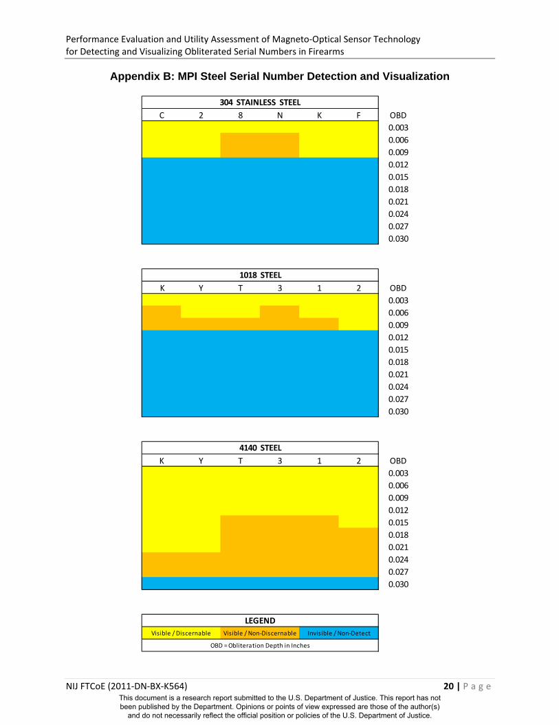
Appendix B: MPI Steel Serial Number Detection and Visualization
C 2 8 N K F OBD
0.003
0.006
0.009
0.012
0.015
0.018
0.021
0.024
0.027
0.030
K Y T 3 1 2 OBD
0.003
0.006
0.009
0.012
0.015
0.018
0.021
0.024
0.027
0.030
K Y T 3 1 2 OBD
0.003
0.006
0.009
0.012
0.015
0.018
0.021
0.024
0.027
0.030
LEGEND
OBD = Obliteration Depth in Inches
Visible / Discernable Visible / Non‐Discernable Invisible / Non‐Detect
304 STAINLESS STEEL
1018 STEEL
4140 STEEL
This document is a research report submitted to the U.S. Department of Justice. This report has not been published by the Department. Opinions or points of view expressed are those of the author(s)
and do not necessarily reflect the official position or policies of the U.S. Department of Justice.

Performance Evaluation and Utility Assessment of Magneto‐Optical Sensor Technology for Detecting and Visualizing Obliterated Serial Numbers in Firearms
NIJ FTCoE (2011‐DN‐BX‐K564) 21 | P a g e
Appendix C: Chemical Etching Steel Serial Number Detection and Visualization
C 2 8 N K F OBD
0.003
0.006
0.009
0.012
0.015
0.018
0.021
0.024
0.027
0.030
K Y T 3 1 2 OBD
0.003
0.006
0.009
0.012
0.015
0.018
0.021
0.024
0.027
0.030
K Y T 3 1 2 OBD
0.003
0.006
0.009
0.012
0.015
0.018
0.021
0.024
0.027
0.030
OBD = Obliteration Depth in Inches
LEGEND
Visible / Discernable Visible / Non‐Discernable Invisible / Non‐Detect
304 STAINLESS STEEL
1018 STEEL
4140 STEEL
This document is a research report submitted to the U.S. Department of Justice. This report has not been published by the Department. Opinions or points of view expressed are those of the author(s)
and do not necessarily reflect the official position or policies of the U.S. Department of Justice.

Performance Evaluation and Utility Assessment of Magneto‐Optical Sensor Technology for Detecting and Visualizing Obliterated Serial Numbers in Firearms
NIJ FTCoE (2011‐DN‐BX‐K564) 22 | P a g e
Appendix D: Chemical Etching Other Substrate Serial Number Detection and Visualization
K Y T 3 1 2 OBD
0.003
0.006
0.009
0.012
0.015
0.018
0.021
K Y T 3 1 2 OBD
0.003
0.006
0.009
0.012
0.015
0.018
0.021
K Y T 3 1 2 OBD
0.003
0.006
0.009
0.012
0.015
0.018
0.021
OBD = Obliterated Depth in Inches
LegendVisible / Discernable Visible / Non‐Discernable Invisible / Non‐Detect
7040 Aluminum
Zinc
Nylon 6 (Polyester)
This document is a research report submitted to the U.S. Department of Justice. This report has not been published by the Department. Opinions or points of view expressed are those of the author(s)
and do not necessarily reflect the official position or policies of the U.S. Department of Justice.

Performance Evaluation and Utility Assessment of Magneto‐Optical Sensor Technology for Detecting and Visualizing Obliterated Serial Numbers in Firearms
NIJ FTCoE (2011‐DN‐BX‐K564) 23 | P a g e
Appendix E: Derivation of MO vs MPI Contingency Table Values
C 2 8 N K F OBD
0.003
0.006
0.009
0.012
0.015
0.018
0.021
0.024
K Y T 3 1 2 OBD
0.003
0.006
0.009
0.012
0.015
0.018
0.021
0.024
K Y T 3 1 2 OBD
0.003
0.006
0.009
0.012
0.015
0.018
0.021
0.024
a N = 55
b N = 46
c N = 1
d N = 42
LegendVisible by MO + MPI
Visible by MO only
MO vs MPI 304 Stainless Steel
MO vs MPI 1018 Steel
Visible by MPI only
Invisible by MO + MPI
MO vs MPI 4140 Steel
Contingency Table EntriesVisible by MO + MPI
Visible by MO only
Visible by MPI only
Invisible by MO + MPI
This document is a research report submitted to the U.S. Department of Justice. This report has not been published by the Department. Opinions or points of view expressed are those of the author(s)
and do not necessarily reflect the official position or policies of the U.S. Department of Justice.

Performance Evaluation and Utility Assessment of Magneto‐Optical Sensor Technology for Detecting and Visualizing Obliterated Serial Numbers in Firearms
NIJ FTCoE (2011‐DN‐BX‐K564) 24 | P a g e
Appendix F: Derivation of MO vs Chemical Etching Contingency Table Values
C 2 8 N K F OBD
0.003
0.006
0.009
0.012
0.015
0.018
0.021
0.024
K Y T 3 1 2 OBD
0.003
0.006
0.009
0.012
0.015
0.018
0.021
0.024
K Y T 3 1 2 OBD
0.003
0.006
0.009
0.012
0.015
0.018
0.021
0.024
a N = 61
b N = 34
c N = 4
d N = 45
MO vs Chemical Etching 1018 Steel
MO vs Chemical Etching 4140 Steel
Invisible by MO + MPI
Contingency Table EntriesVisible by MO + MPI
Visible by MO only
Visible by MPI only
LegendVisible by MO + MPI
Visible by MO only
Visible by MPI only
Invisible by MO + MPI
MO vs Chemical Etching 304 Stainless Steel
This document is a research report submitted to the U.S. Department of Justice. This report has not been published by the Department. Opinions or points of view expressed are those of the author(s)
and do not necessarily reflect the official position or policies of the U.S. Department of Justice.