Perancangan Proses Manufaktur D0394 Perancangan Sistem Manufaktur Pertemuan V - VIII.
52
Perancangan Proses Manufaktur D0394 Perancangan Sistem Manufaktur Pertemuan V - VIII
-
date post
21-Dec-2015 -
Category
Documents
-
view
248 -
download
3
Transcript of Perancangan Proses Manufaktur D0394 Perancangan Sistem Manufaktur Pertemuan V - VIII.

Perancangan Proses Manufaktur
D0394 Perancangan Sistem Manufaktur
Pertemuan V - VIII

Perencanaan Proses
• Process planning is the function within a manufacturing facility that establishes which processes and parameters are to be used (as well as those machines capable of performing theses processes) to convert a piece part from its initial form to a final form predetermined in an engineering drawing.
• Alternatively, process planning could be defined as the act of preparing detailed work instructions to produce a part. (Chang et al., 1993, p.399)

Perencanaan Proses
• νDefined as the systematic determination of the method by which a product may be manufactured economically and competitively.νFor a machined part, provides information regarding specific material, machines, tools, holding devices, cutting fluids, and cutting parameters.

Definition
Process planning is also called: manufacturing planning, process planning, material processing, process engineering, and machine routing.
• Which machining processes and parameters are to be used (as well as those machines capable of performing these processes) to convert (machine) a piece part from its initial form to a final form predetermined (usually by a design engineer) from an engineering drawing.
• The act of preparing detailed work instructions to produce a part.
• How to realize a given product design.
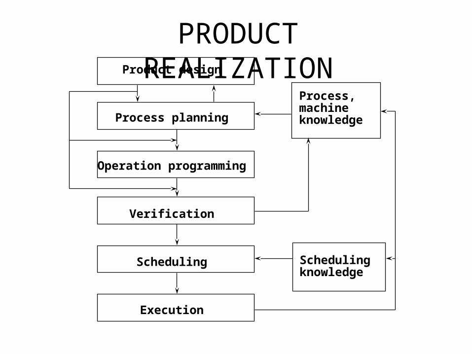
PRODUCT REALIZATIONProduct design
Process planning
Operation programming
Verification
Scheduling
Execution
Process,machineknowledge
Schedulingknowledge
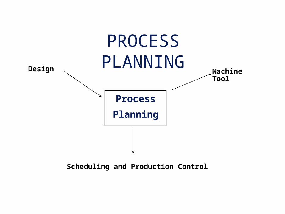
PROCESS PLANNINGDesign Machine
Tool
Scheduling and Production Control
Process
Planning

PROBLEMS FACING MANUFACTURING
INDUSTRYFact:
Only 11% of the machine tools in the U.S. are programmable.
More than 53% of the metal-working plants in the U.S. do not have even one computer-controlled machine.
Some problems:
Cannot justify the cost
Lack of expertise in using such machines
Too small a batch size to offset the planning and programming costs
Source: Kelley, M.R. and Brooks, H., The State of Computerized Automation in US Manufacturing, J.F. Kennedy School of Government, Harvard University, October 1988.
Potential benefits in reducing turnaround time by using programmable machine tools have not been realized due to time, complexity and costs of planning and programming.

DOMAINOne-of-a-kind and Small batch
Objectives: Lead-time, Cost
Approaches: process selection, use
existing facilities.
Mass productionObjective: Cost
Approaches: process design, optimization,
materials selection, facilities
design

ENGINEERING DESIGN MODELING 10" +0.01
-0.01
1'-4" +0.01-0.01
4" +0.01-0.01
7" +0.05-0.05
5" +0.01-0.01
3" +0.01-0.01
2" +0.01-0.01 0.001 A B
A
B
S.F. 64 u inch
U*
- *
CSG MODEL
Face
Loop
Edge
Vertex
B-REP MODEL

INTERACTION OF PLANNING
FUNCTIONSGEOMETRIC REASONING
PROCESS SELECTION
CUTTER SELECTION
MACHINE TOOL SELECTION
SETUP PLANNING
FIXTURE PLANNING
CUTTER PATH GENERATION
• global & local geometry
• process capability• process cost
• available tools• tool dimension and geometry• geometric constraints
• machine availability, cost• machine capability
• feature relationship• approach directions• process constraints• fixture constraints
• fixture element function• locating, supporting, and clamping surfaces• stability
• feature merging and split• path optimization• obstacle and interference avoidance

PROCESS PLAN
• Also called : operation sheet, route sheet, operation planning summary, or another similar name.
• The detailed plan contains:
route
processes
process parameters
machine and tool selections
fixtures
• How detail the plan is depends on the application.
• Operation: a process
• Operation Plan (Op-plan): contains the description of an operation, includes tools, machines to be used, process parameters, machining time, etc.
• Op-plan sequence: Summary of a process plan.

EXAMPLE PROCESS PLANSRoute Sheet
Part No. S1243Part Name: Mounting Bracket
1. Mtl Rm2. Mill02 5 3. Drl01 44. Insp 1
workstation Time(min)
by: T.C. Chang
PROCESS PLAN ACE Inc.
Part No. S0125-FPart Name: HousingOriginal: S.D. Smart Date: 1/1/89Checked: C.S. Good Date: 2/1/89
Material: steel 4340Si
Changes: Date: Approved: T.C. Chang Date: 2/14/89
No. OperationDescription
Workstation Setup Tool Time(Min)
10 Mill bottom surface1 MILL01 see attach#1for illustration
Face mill6 teeth/4" dia
3 setup5 machining
20 Mill top surface MILL01 see attach#1 Face mill6 teeth/4" dia
2 setup6 machining
30 Drill 4 holes DRL02 set on surface1 twist drill1/2" dia2" long
2 setup3 machining
Detailed plan
Rough plan
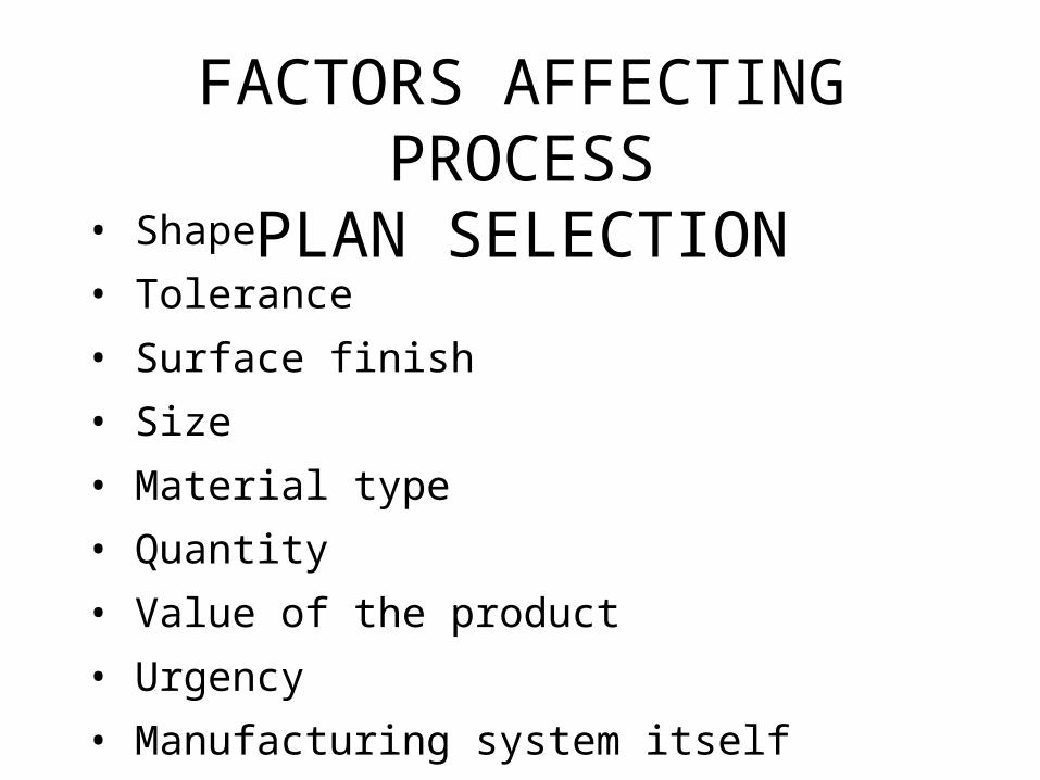
FACTORS AFFECTING PROCESS
PLAN SELECTION• Shape
• Tolerance
• Surface finish
• Size
• Material type
• Quantity
• Value of the product
• Urgency
• Manufacturing system itself
• etc.

PROCESS PLANNING CLASSIFICATIONMANUAL
COMPUTER-AIDED
VARIANT
GT based
Computer aids for editing
Parameters selection
GENERATIVE
Some kind of decision logic
Decision tree/table
Artificial Intelligence
Objective-Oriented
Still experience based
AUTOMATIC
Design understanding
Geometric reasoning capability
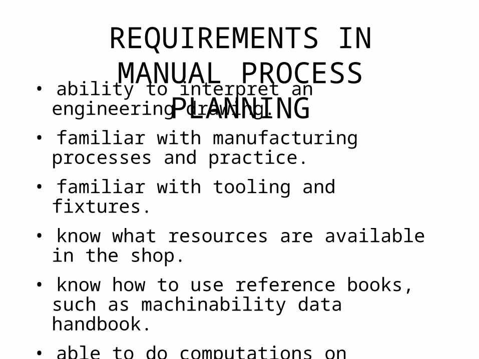
REQUIREMENTS INMANUAL PROCESS
PLANNING• ability to interpret an engineering drawing.
• familiar with manufacturing processes and practice.
• familiar with tooling and fixtures.
• know what resources are available in the shop.
• know how to use reference books, such as machinability data handbook.
• able to do computations on machining time and cost.
• familiar with the raw materials.
• know the relative costs of processes, tooling, and raw materials.

INDUSTRIAL SOLUTION
10" +0.01-0.01
1'-4" +0.01-0.01
4" +0.01-0.01
7" +0.05-0.05
5" +0.01-0.01
3" +0.01-0.01
2" +0.01-0.01 0.001 A B
A
B
S.F. 64 u inch
PRODUCTCONCEPT
CAD
CAMCUTTER PATH
HUMAN - decision makingCOMPUTER - geometric computation, data handling
N0010 G70 G 90 T08 M06
N0020 G00 X2.125 Y-0.475 Z4.000 S3157
N0030 G01 Z1.500 F63 M03
N0040 G01 Y4.100
N0050 G01 X2.625
N0060 G01 Y1.375
N0070 G01 X3.000
N0080 G03 Y2.625 I3.000 J2.000
N0090 G01 Y2.000
N0100 G01 X2.625
N0110 G01 Y-0.100
N0120 G00 Z4.000 T02 M05
N0130 F9.16 S509 M06
N0140 G81 X0.750 Y1.000 Z-0.1 R2.100 M03
N0150 G81 X0.750 Y3.000 Z-0.1 R2.100
N0160 G00 X-1.000 Y-1.000 M30
.

PROCESS PLANNING STEPS• Study the overall shape of the part. Use this
information to classify the part and determine the type of workstation needed.
• Thoroughly study the drawing. Try to identify every manufacturing features and notes.
• If raw stock is not given, determine the best raw material shape to use.
• Identify datum surfaces. Use information on datum surfaces to determine the setups.
• Select machines for each setup.
• For each setup determine the rough sequence of operations necessary to create all the features.

PROCESS PLANNING STEPS
(continue)• Sequence the operations determined in the previous
step.
• Select tools for each operation. Try to use the same tool for several operations if it is possible. Keep in mind the trade off on tool change time and estimated machining time.
• Select or design fixtures for each setup.
• Evaluate the plan generate thus far and make necessary modifications.
• Select cutting parameters for each operation.
• Prepare the final process plan document.
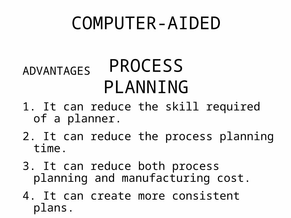
COMPUTER-AIDED
PROCESS PLANNING
ADVANTAGES
1. It can reduce the skill required of a planner.
2. It can reduce the process planning time.
3. It can reduce both process planning and manufacturing cost.
4. It can create more consistent plans.
5. It can produce more accurate plans.
6. It can increase productivity.
WHY AUTOMATED
PROCESS PLANNING
• Shortening the lead-time
• Manufacturability feedback
• Lowering the production cost
• Consistent process plans

PROCESS PLANNING
Machining featuresDesign
Workpiece SelectionProcess SelectionTool SelectionFeed, Speed SelectionOperation SequencingSetup PlanningFixturing PlanningPart Programming

VARIANT PROCESS PLANNING
Standardprocess plans &individualprocessplans
processplanediting
part coding
partfamilyformation
standardplanpreparation
part coding
partfamilysearch
processplanretrieval
finishedprocessplan
GROUP TECHNOLOGY BASED RETRIEVAL SYSTEM
PROBLEMS ASSOCIATED WITH
THE VARIANT APPROACH1. The components to be planned are limited to similar components previously planned.
2. Experienced process planners are still required to modify the standard plan for the specific component.
3. Details of the plan cannot be generated.
4. Variant planning cannot be used in an entirely automated manufacturing system, without additional process planning.
ADVANTAGES OF THE
VARIANT APPROACH
1. Once a standard plan has been written, a variety of components can be planned.
2. Comparatively simple programming and installation (compared with generative systems) is required to implement a planning system.
3. The system is understandable, and the planner has control of the final plan.
4. It is easy to learn, and easy to use.

GENERATIVE APPROACHA system which automatically synthesizes a
process plan for a new component.
(i) part description
(ii) manufacturing databases
(iii) decision making logic and algorithms
MAJOR COMPONENTS:

ADVANTAGES OF THE
GENERATIVE APPROACH
1. Generate consistent process plans rapidly;
2. New components can be planned as easily as existing components;
3. It has potential for integrating with an automated manufacturing facility to provide detailed control information.

KEY DEVELOPMENTS
1. The logic of process planning must be identified and captured.
2. The part to be produced must be clearly and precisely defined in a computer-compatible format
3. The captured logic of process planning and the part description
PRODUCT REPRESENTATIONGeometrical information
Part shape
Design features
Technological information
Tolerances
Surface quality (surface finish, surface integrity)
Special manufacturing notes
Etc.
"Feature information"
Manufacturing features
e.g. slots, holes, pockets, etc.

INPUT REPRESENTATION SELECTION• How much information is needed?
• Data format required.
• Ease of use for the planning.
• Interface with other functions, such as, part programming, design, etc.
• Easy recognition of manufacturing features.
• Easy extraction of planning information from the representation.
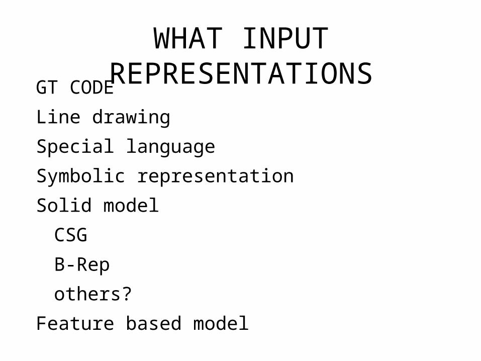
WHAT INPUT REPRESENTATIONSGT CODE
Line drawing
Special language
Symbolic representation
Solid model
CSG
B-Rep
others?
Feature based model

SPECIAL LANGUAGE
10 CYLINDER/3,1/11 DFIT/K,5/12 CHAMFER/.2,2.6/20 CYLINDER/2.5,1.2/21 LTOL/+0.001,-0.001/
3
11.2
2.5
.2x2.6
K5
+.001-.001
AUTAP
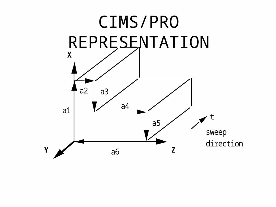
CIMS/PRO REPRESENTATION
a1
a2 a3
a4
a5
a6
t
X
Y Z
sweepdirection

GARI REPRESENTATION
0 3.0
2.5
0 1.
X
Y3.0
F1
F2
F3
(F1 (type face) (direction xp) (quality 120))
(F2 (type face) (direction yp) (quality 64))
(F3 (type face) (direction ym) (quality rough))
(H1 (type countersunk-hole) (diameter 1.0)
(countersik-diameter 3.0)
(starting-from F2) (opening-into F3))
(distance H1 F1 3.0)
(countersink-depth F2 H1 0.5)

CONCEPT OF FEATURE
Manufacturing is "feature" based.
Feature:
1 a: the structure, form, or appearance esp. of a person
b: obs: physical beauty.
2 a: the makeup or appearance of the face or its parts
b: a part of the face: LINEAMENT
3: a prominent part or characteristic
4: a special attraction
Webster's Ninth New Collegiate Dictionary
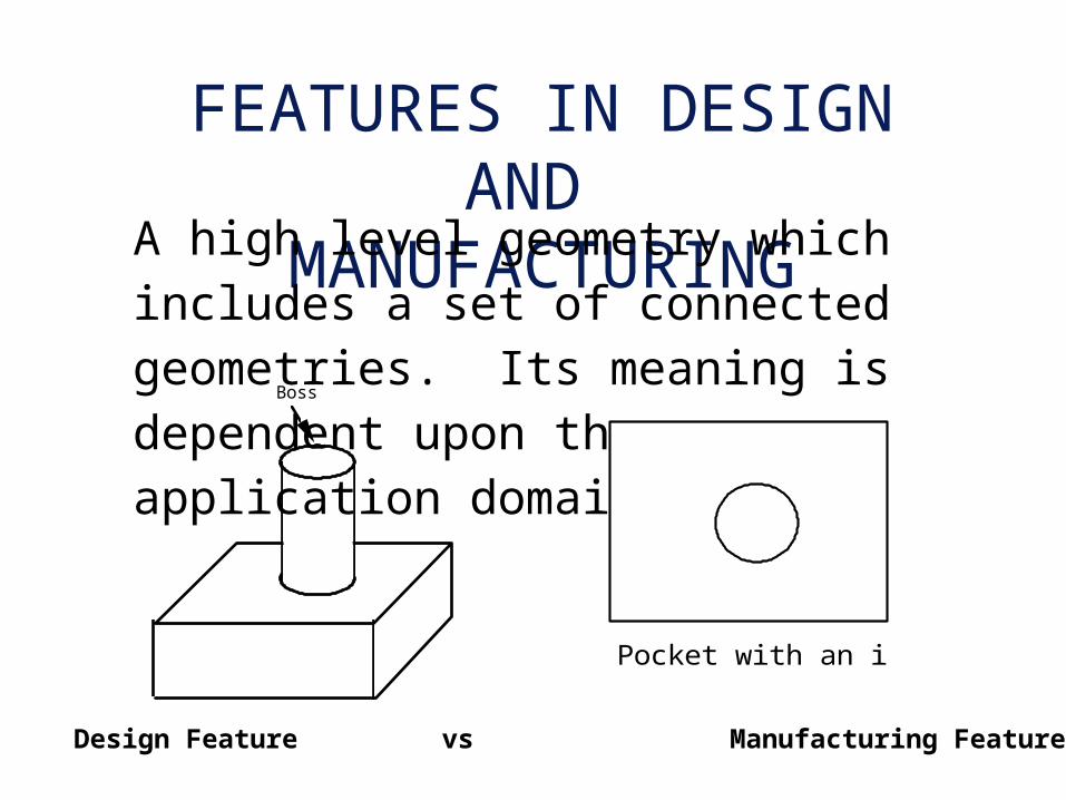
FEATURES IN DESIGN AND
MANUFACTURINGA high level geometry which includes a set of connected geometries. Its meaning is dependent upon the application domain.
Boss
Pocket with an island
Design Feature vs Manufacturing Feature

DESIGN FEATURES• For creating a shape
• For providing a function
Motion Slot feature

MANUFACTURING FEATURES
• For process selection
• For fixturing
End mill a slot
Drilling Round hole
Turning Rotational feature
End milling Plane surface,
Hole, profile, slot
Ball end mill Free form surface
Boring Cylindrical shell
Reaming Cylindrical shell
... ...
Manufacturing is feature based.
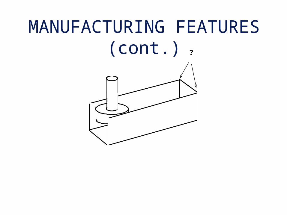
MANUFACTURING FEATURES (cont.) ?
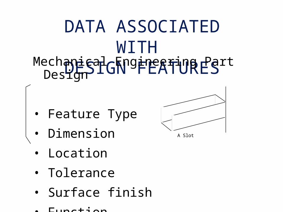
DATA ASSOCIATED WITH
DESIGN FEATURESMechanical Engineering Part Design
• Feature Type
• Dimension
• Location
• Tolerance
• Surface finish
• Function
A Slot

DATA ASSOCIATED WITH
MANUFACTURING FEATURES
• Feature type
• Dimension
• Location
• Tolerance
• Surface finish
• Relations with other features
• Approach directions
Approach
Approach
° Feature classifications are not the same.

FEATURE RECOGNITIONExtract and decompose features from a
geometric model.
• Syntactic pattern recognition
• State transition diagram and automata
• Decomposition
• Logic
• Graph matching
• Face growing

DIFFICULTIES OF FEATURE
RECOGNITION• Potentially large number of features.
• Features are domain and user specific.
• Lack of a theory in features.
• Input geometric model specific. Based on incomplete models.
• Computational complexity of the algorithms.
• Existing algorithms are limited to simple features.
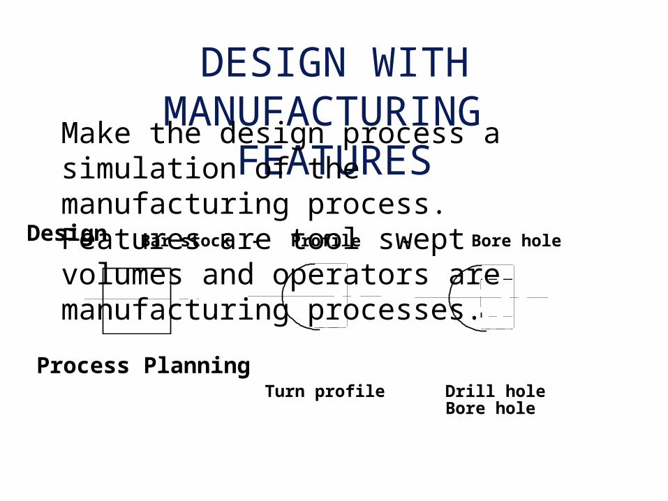
DESIGN WITH MANUFACTURING
FEATURESMake the design process a simulation of the manufacturing process. Features are tool swept volumes and operators are manufacturing processes.Design
Process Planning
Bar stock - Profile - Bore hole
Turn profile Drill holeBore hole

PROS AND CONS OF DESIGN WITH
MANUFACTURING FEATURES
• Concurrent engineering - designers are forced to think about manufacturing process.
• Simplify (eliminate) process planning.
• Hinder the creative thinking of designers.
• Use the wrong talent (designer doing process planning).
• Interaction of features affects processes.
Pros
Cons

BACKWARD PLANNING
.
Boring
Drilling
Milling
Finishedpart
Workpiece
P la n n i n g
M a c h in in g o p e ra t io n

PROCESS KNOWLEDGE
REPRESENTATION• Predicate logic
• Production rules
• Semantic Nets
• Frames
• Object Oriented Programming

SOME RESEARCH ISSUES
• Part design representation: information contents, data format
• Geometric reasoning: feature recognition, feature extraction, tool approach directions, feature relations
• Process selection: backward planning, tolerance analysis, geometric capability, process knowledge, process mechanics
• Tool selection: size, length, cut length, shank length, holder, materials, geometry, roughing, and finishing tools

SOME RESEARCH ISSUES
(continue)• Fixture design: fixture element model, fixturing knowledge modeling, stability analysis, friction/cutting force
• Tool path planning: algorithms for features, gauging and interference avoidance algorithms, automated path generation
• Software engineering issues: data structure, data base, knowledge base, planning algorithms, user interface, software interface

A FEATURE BASED DESIGN/
PROCESS PLANNING SYSTEMGeometric Reasoning
Application-Specific Features (e.g. manufacturing features)
blind slot, through slot, step, etc.
approach direction, feed direction
feature relations: precedence and intersection type
Manufacturing-Oriented Design Features
hole, straight slot, T-slot, circular slot, pocket
counterbore, sculptured surface cavity
Principle:
Provide designer with the freedom to describe shape -
avoid constraining manufacturing planning
or requiring detailed manufacturing knowledge.
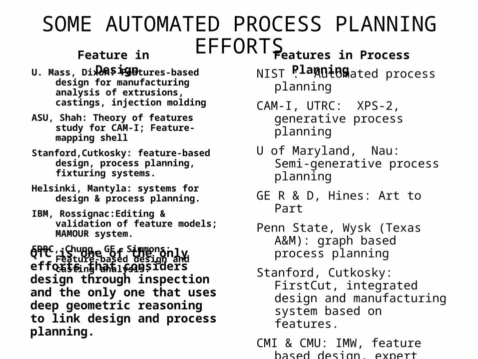
SOME AUTOMATED PROCESS PLANNING EFFORTS
U. Mass, Dixon: Features-based design for manufacturing analysis of extrusions, castings, injection molding
ASU, Shah: Theory of features study for CAM-I; Feature-mapping shell
Stanford,Cutkosky: feature-based design, process planning, fixturing systems.
Helsinki, Mantyla: systems for design & process planning.
IBM, Rossignac:Editing & validation of feature models; MAMOUR system.
SDRC, Chung, GE, Simmons: Feature-based design and casting analysis.
NIST : Automated process planning
CAM-I, UTRC: XPS-2, generative process planning
U of Maryland, Nau: Semi-generative process planning
GE R & D, Hines: Art to Part
Penn State, Wysk (Texas A&M): graph based process planning
Stanford, Cutkosky: FirstCut, integrated design and manufacturing system based on features.
CMI & CMU: IMW, feature based design, expert operation planning.
U. of Twente, Holland, Kals: PARTS , feature based input, feature recognition, operation planning.
Allied Bendix, Hummel & Brooks: XCUT system for cavity operation planning.
IPK Berlin & IPK Aachen
UMIST, B.J. Davies
U. of Leeds, de Pennington
U. of Tokyo, Kimura
Features in Process PlanningFeature in Design
QTC is one of the only efforts that considers design through inspection and the only one that uses deep geometric reasoning to link design and process planning.
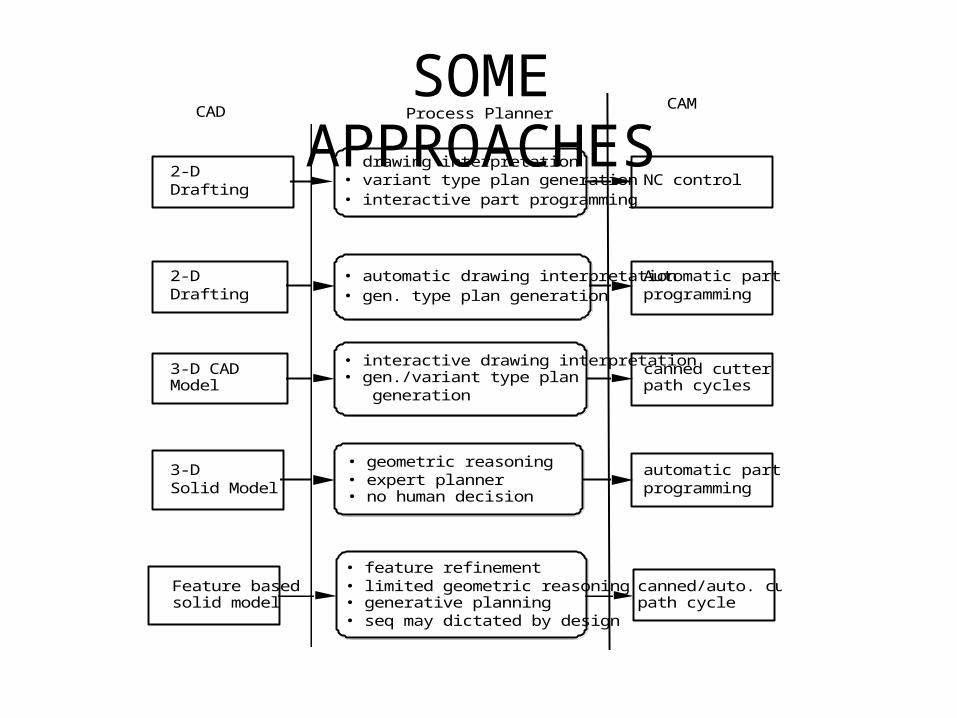
SOME APPROACHES
CADCAM
2-D Drafting
Process Planner
• automatic drawing interpretation• gen. type plan generation
Automatic part programming
3-D Solid Model
canned/auto. cutter path cycle
Feature based solid model
automatic part programming
• feature refinement • limited geometric reasoning • generative planning • seq may dictated by design
2-D Drafting
• drawing interpretation• variant type plan generation • interactive part programming
NC control
3-D CAD Model
• interactive drawing interpretation • gen./variant type plan generation
canned cutter path cycles
• geometric reasoning • expert planner • no human decision
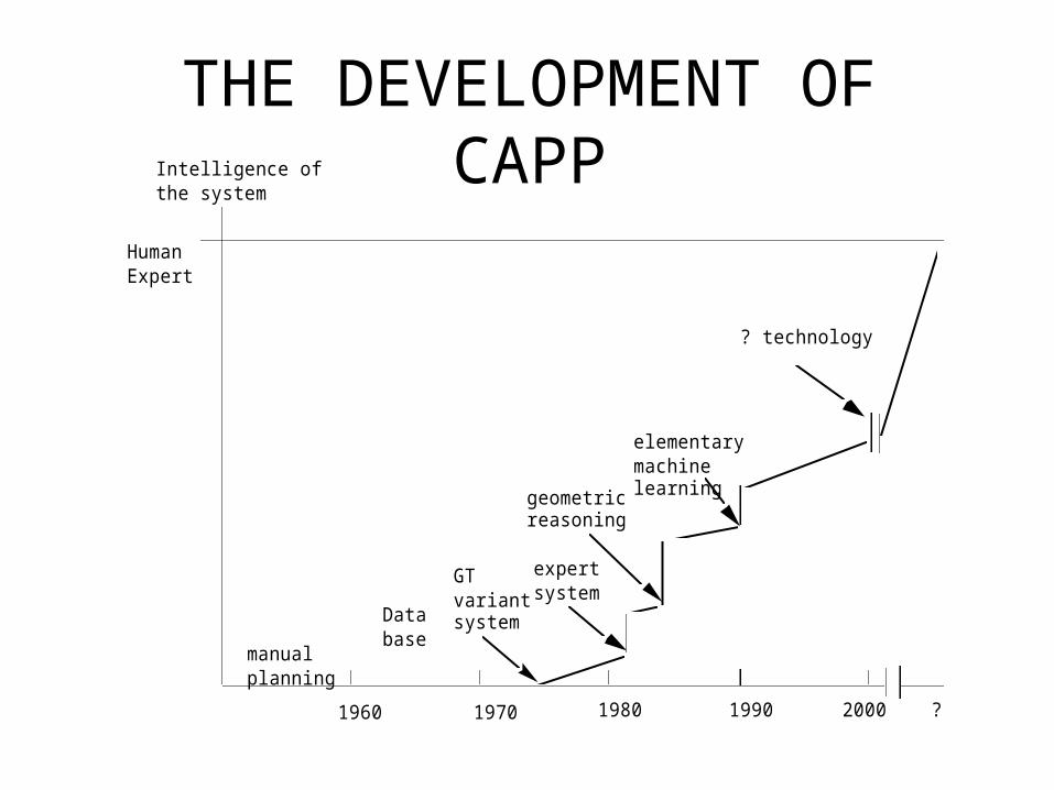
THE DEVELOPMENT OF CAPP
1960 1970 1980 1990 2000
Intelligence of the system
Human Expert
?
manual planning
Data base
GT variant system
expert system
geometric reasoning
elementary machine learning
? technology