PELTON WHEEL CHARACTERISTICS.doc
13
Last Rev.: 19 JUN 08 Pelton Wheel: MIME 3470 Page 1 Grading Sheet ~~~~~~~~~~~~~~ MIME 3470—Thermal Science Laboratory ~~~~~~~~~~~~~~ Laboratory №. 11 PELTON WHEEL PERFORMANCE CHARACTERISTICS Students’ Names Section № POINTS SCORE TOTAL PRESENTATION—Applicable to Both MS Word and Mathcad Sections GENERAL APPEARANCE, ORGANIZATION, ENGLISH, & GRAMMAR 5 ORDERED DATA, CALCULATIONS & RESULTS—MATHCAD CALCULATIONS 30 COMBINED PLOT 25 DISCUSSION OF RESULTS WHAT ARE TWO FEATURES OBSERVED FROM COMBINED PLOT? 5 WHY IS THE BUCKET EXIT ANGLE SMALL AND NONZERO? 5 WHAT IS PURPOSE OF CUTOUT AT BUCKET PERIPHERY? 5 WHAT IS THE MAXIMUM UTILIZATION FACTOR WHEN 2 = 0? 5 WHY MUST A TURBINE W/ NONZERO HAVE A ROTOR ENCLOSED? 5 WHY DOES THE RELATIVE VELOCITY REMAIN UNCHANGED AS THE FLOW PASSES THROUGH A PELTON BUCKET? 5 CONCLUSIONS 5 ORIGINAL DATASHEET 5 TOTAL 100 COMMENTS
-
Upload
tanvir-ibny-gias-liton -
Category
Documents
-
view
71 -
download
3
description
description about pelton wheei in details
Transcript of PELTON WHEEL CHARACTERISTICS.doc

Last Rev.: 19 JUN 08 Pelton Wheel: MIME 3470 Page 1
Grading Sheet~~~~~~~~~~~~~~
MIME 3470—Thermal Science Laboratory~~~~~~~~~~~~~~Laboratory №. 11
PELTON WHEEL
PERFORMANCE CHARACTERISTICS
Students’ Names Section №POINTS SCORE TOTAL
PRESENTATION—Applicable to Both MS Word and Mathcad Sections
GENERAL APPEARANCE, ORGANIZATION, ENGLISH, & GRAMMAR 5ORDERED DATA, CALCULATIONS & RESULTS—MATHCAD
CALCULATIONS 30 COMBINED PLOT 25DISCUSSION OF RESULTS
WHAT ARE TWO FEATURES OBSERVED FROM COMBINED PLOT? 5 WHY IS THE BUCKET EXIT ANGLE SMALL AND NONZERO? 5 WHAT IS PURPOSE OF CUTOUT AT BUCKET PERIPHERY? 5 WHAT IS THE MAXIMUM UTILIZATION FACTOR WHEN 2 = 0? 5 WHY MUST A TURBINE W/ NONZERO HAVE A ROTOR ENCLOSED? 5 WHY DOES THE RELATIVE VELOCITY REMAIN UNCHANGED AS THE FLOW PASSES THROUGH A PELTON BUCKET? 5
CONCLUSIONS 5ORIGINAL DATASHEET 5
TOTAL 100
COMMENTS
GRADER—d

Last Rev.: 19 JUN 08 Pelton Wheel: MIME 3470 Page 2
Last Rev.: 19 JUN 08 Pelton Wheel: MIME 3470 Page 3
MIME 3470—Thermal Science Laboratory~~~~~~~~~~~~~~Laboratory №. 11
PELTON WHEEL PERFORMANCE CHARACTERISTICS
~~~~~~~~~~~~~~LAB PARTNERS: NAME NAME
NAME NAME
NAME NAME
SECTION №EXPERIMENT TIME/DATE: TIME, DATE
~~~~~~~~~~~~~~OBJECTIVE—of this experiment is to plot the Pelton wheel actual and theoretical horsepowers vs. U/V1 (explained below) and to demonstrate that maximum power occurs when U/V1 0.5.
INTRODUCTIONA water turbine1
is a rotary engine2 that takes energy from moving
water. The Pelton wheel is such a device.
The earliest water turbines were water wheels which have been used for thousands of years for industrial power. Their main shortco-ming is size, which limits the flow rate and head that can be used.
The migration from water wheels to modern, more efficient tur-bines took during the 19th century during the Industrial Revolution. Efficiency improvements of water turbines allowed them to compete with steam engines (wherever water was available). These turbines (using scientific principles, new materials, and, new manufacturing methods) were widely used for industrial power prior to electrical grids. Now they are mostly used for electric power generation.
The main difference between early water turbines and water wheels is a swirl component of the water which passes energy to a spinning rotor. Swirl is the tangential velocity component induced by a curved impeller. This additional component of motion allowed the turbine to be smaller than a water wheel of the same power. They could process more water by spinning faster and could harness much greater heads. Later, impulse turbines such as the Pelton wheel were developed which did not use swirl.
THEORY
Euler Turbine EquationALL turbines have a runner or rotor which holds the turbine vanes or blades. In the case of a water wheel, the vanes are simple paddles. This runner and attached vanes rotate as flowing water is directed onto the vanes. Since the runner is spinning, the imparted water force acting through a distance generates work. In this way, energy is transferred from the water flow to the turbine.
The basic design relationship for all turbomachines is very simple and is only a form of Newton’s Laws of Motion applied to fluid traversing a rotor. Imagine water impinging on a turbine runner at Point 1 at some arbitrary angle and at rotor radius r1. Further, the fluid exits the runner at Point 2 having some other arbitrary angle and at rotor radius r2. Also, the flow is assumed to be an unchanging steady-state at every point in the system. The fluid velocity vector at any point can be resolved into three mutually perpendicular components:
Va – an axial component directed parallel to the axis of rotation, Vm – a radial component directed radially outward from the axis
of rotation, and Vu – a tangential component directed parallel to the tangential
velocity of the rotor, U.
The change in magnitude in axial and radial components causes forces must be carried by the bearings. These forces, however, do not affect the angular rotation of the rotor except through bearing friction.
However, the change in magnitude and of radius of the tangential velocity components corresponds to a change in angular momentum of the fluid and by Newton’s Laws of Motion is equal to the summation of all the applied forces on the rotor; i.e., the net torque on the rotor, . In general terms, this is as follows. If a mass of fluid M1 enters the rotor at radius r1, with tangential component
of absolute velocity during time t; and, if during the same
time t a mass M2 leaves the rotor at radius r2 with tangential
component of absolute velocity ; then
For a unit mass steady flow, this
becomes . For a steady rotor
angular velocity of , the rate of energy transferred or utilized Eutil
= . Further, the linear velocity of the rotor is U = r. Combining all this yields
(1)
This is one form of the Euler turbine equation or simply the Euler equation.3
Degree of Reaction The relative proportions of energy transfer obtained by change
of both static and dynamic pressures are important factors with respect to classifying turbomachines, as for a given class of machine this proportion inevitably leads to a particular type of design with certain inherent characteristics. The parameter used to describe this relation is the degree of reaction or more simply the reaction, R, which is defined as the ratio of the energy transfer by means of or resulting in a change of static pressure in the rotor to the total energy transfer to (utilized by) the rotor.
(2)
where, Total energy transferred to the rotor
linear velocity of the rotor at radius r, = r
absolute velocity
tangential component of absolute velocity
velocity relative to the moving rotor
R, can be negative, zero, and values greater than unity.
Reaction TurbinesWater turbines are either reaction turbines or impulse turbines. All common water turbines until the late 19th
century were reaction
1 turbine: word coined by the French engineer Claude Bourdin in the early 19th
century and is derived from the Latin word for “whirling” or a “vortex”.2 engine: a mechanical device producing some form of output from a given input.
3 This should not be confused with the Euler flow equation which is simply the Navier-Stokes equation without viscosity effects.

Last Rev.: 19 JUN 08 Pelton Wheel: MIME 3470 Page 4
turbines. Reaction turbines are acted on by water, which changes static pressure as it moves through the turbine and gives up its energy. The flow between the rotating vanes of a reaction turbine can be envisioned as flow through rotating nozzles. The pressures within the moving nozzle produce work. The flow must be encased to contain the water pressure (or suction), in order that the fluid cannot expand freely in all directions. Alternately, the vanes must be fully submerged in the water flow as with a ship’s propeller.
Most water turbines in use are reaction turbines—even a simple spinning lawn sprinkler. They are used in low and medium head applications. Two popular types of reaction turbines are the Francis and the Kaplan turbines.
In 1826, Benoit Fourneyron developed a high efficiency (80%) outward flow water turbine. Water was directed tangentially through the turbine runner causing it to spin. Jean-Victor Poncelet designed an inward-flow turbine in about 1820 that used the same principles. S. B. Howd obtained a U.S. patent in 1838 for a similar design.
In 1848, James B. Francis improved on the inward-flow design to create a turbine with 90% efficiency. It is also called a radial-flow turbine He applied scientific principles and testing methods to produce the most efficient turbine design ever. More importantly, his mathematical and graphical calculation methods improved the state of the art of turbine design and engineering. His analytical methods allowed confident design of high efficiency turbines to exactly match a site’s flow conditions.
Francis turbines are the most common water turbine in use today. They operate in a head range of ten meters to several hundred meters and are primarily used for electrical power production.
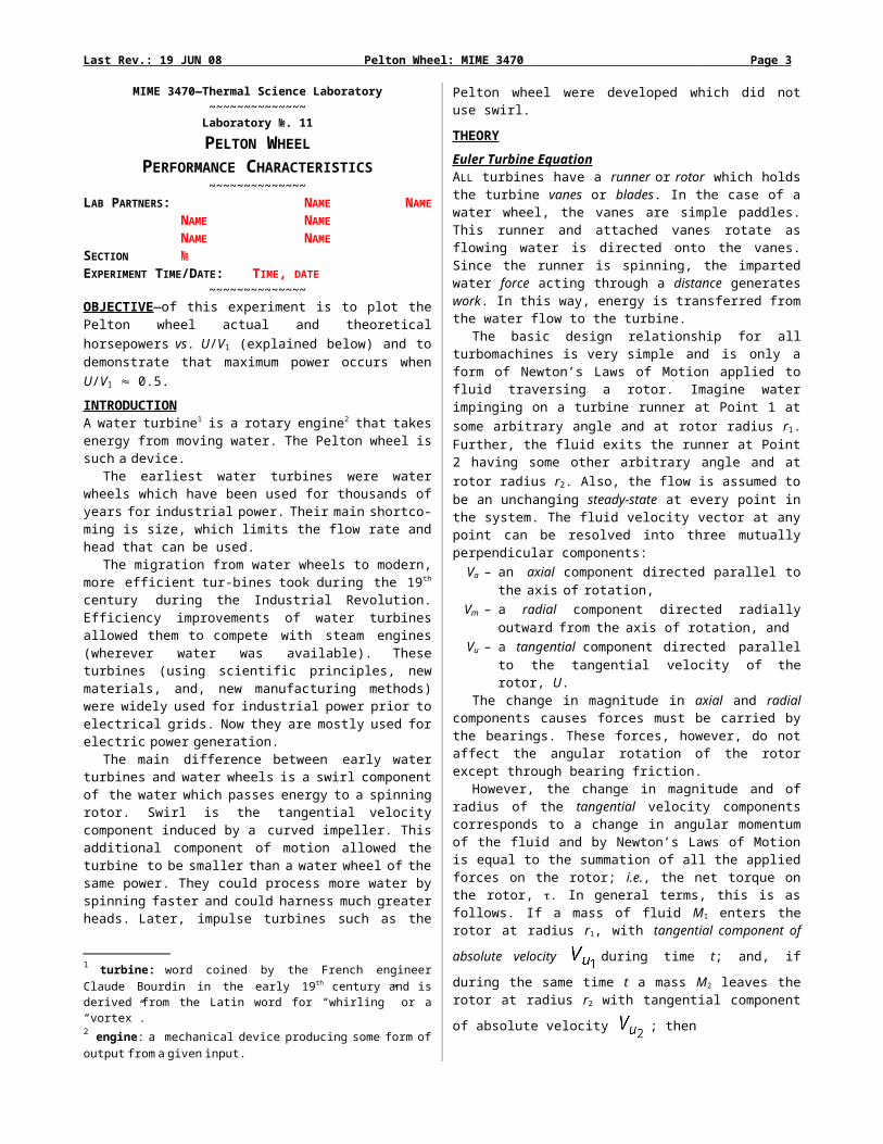
Figure 1—Francis Turbine: (a) Cross section, (b) Runner used in Grand Coulee Dam
The Kaplan turbine is an inward-flow, propeller-type water turbine that has adjustable blades developed in 1913 by the Austrian professor Viktor Kaplan. It was an evolution of the Francis turbine.
Figure 2—Kaplan Propeller Turbine
Its invention allowed efficient power production in low head applications that was not possible with Francis turbines. Kaplan turbines are now widely used throughout the world in high-flow, low-head power production. Their efficiencies are typically over 90%, but may be lower in very low head applications. Again, most water turbines in use are reaction turbines. They are used in low and medium head applications.
Impulse Turbines Zero reaction (R = 0) is an important value and characterizes a particular design of many types of turbomachine. The Knight and Pelton bucket wheels are examples of zero reaction turbines.
In 1866, California millwright Samuel Knight invented a machine that worked from a different concept. Inspired by the high pressure jet systems used in hydraulic mining in the gold fields, Knight developed a wheel where the vanes were bucket-like which captured the energy of a free jet, which had converted a high head (hundreds of vertical feet in a pipe or penstock) of water to kinetic energy. This is called an impulse or tangential turbine. The water's velocity, roughly twice the velocity of the bucket periphery, does a U-turn in the bucket and drops out of the runner at low velocity.
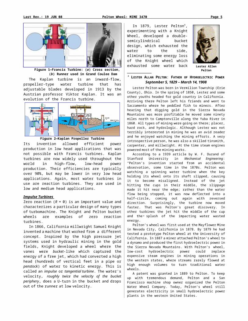
In 1879, Lester Pelton4, experimenting with a Knight Wheel, developed a double-semicylindrical bucket design, which exhausted the water to the side, eliminating some energy loss of the Knight wheel which exhausted some water back against the center of the wheel. In about 1895, William Doble improved on Pelton's half-cylindrical bucket form with an elliptical bucket that included a cutout in it to allow the jet a cleaner bucket exit by centrifugal force. This is the modern form of the Pelton turbine which today achieves up to 92% efficiency. Pelton had been quite an effective promoter of his design and although Doble took over the Pelton company he did not change the name because it had brand name recognition.
So, if R = 0, there is no change of static pressure in the rotor and such a turbine is an impulse-type. In these machines, prior to
4 LESTER ALLAN PELTON: FATHER OF HYDROELECTRIC POWER
September 5, 1829 – March 14, 1908Lester Pelton was born in Vermilion Township (Erie County), Ohio. In the spring of 1850, Lester and some other youths headed for gold country in
California. Arriving there Pelton left his friends and went to Sacramento where he peddled fish to miners. After hearing that digging gold in the Sierra Nevada Mountains was more profitable he moved some ninety miles north to Camptonville along the Yuba River in 1860. All types of mining were going on there; placer, hard rock, and hydrologic. Although Lester was not terribly interested in mining he was an avid reader and he enjoyed watching the mining efforts. A very introspective person, he was also a skilled tinsmith, carpenter, and millwright. At the time steam engines powered most of the mining works.
According to a 1939 article by W. F. Durand of Stanford University in Mechanical Engineering: “Pelton's invention started from an accidental observation, some time in the 1870s. Pelton was watching a spinning water turbine when the key holding its wheel onto its shaft slipped, causing it to become misaligned. Instead of the jet hitting the cups in their middle, the slippage made it hit near the edge; rather than the water flow being stopped, it was now deflected into a half-circle, coming out again with reversed direction. Surprisingly, the turbine now moved faster. That was Pelton's great discovery. In other turbines the jet hit the middle of the cup and the splash of the impacting water wasted energy.”
Pelton’s wheel was first used at the Mayflower Mine in Nevada City, California in 1878. By 1879 he had tested a prototype Pelton wheel at the University of California. In 1887 a miner attached Pelton's wheel to a dynamo and produced the first hydroelectric power in the Sierra Nevada Mountains. With Pelton’s wheel, low-cost hydroelectric power could replace expensive steam engines in mining operations in the western states, where streams rarely flowed at high enough volumes to turn traditional water wheels.
A patent was granted in 1889 to Pelton. To keep up with tremendous demand, Pelton and a San Francisco machine shop owner organized the Pelton Water Wheel Company. Today, Pelton’s wheel still generates electricity in small hydroelectric power plants in the western United States.
Lester Allen Pelton
Last Rev.: 19 JUN 08 Pelton Wheel: MIME 3470 Page 5
hitting the buckets, the water’s head pressure (potential energy) is entirely converted to kinetic energy by a nozzle and focused on the turbine (see Figure 3). As the nozzle is stationary, it performs no work even though force is transferred to it as it accelerates the flow. As no pressure change occurs at the turbine blades the turbine doesn't require an enclosing housing.
Utilization Factor The quality of interest in a turbine is the adiabatic efficiency which is usually taken to be equal to the overall efficiency, since mechanical efficiency is nearly unity. However, the adiabatic efficiency is also the product of two factors, the first factor being referred to as the utilization factor or diagram efficiency is the ratio of the ideal work output to the energy available for conversion into work. The value of the utilization factor may be found from the ideal velocity diagrams and the energy equations. Under ideal conditions, it should be possible to use all of the available kinetic energy of the liquid at the turbine inlet and also the energy obtained in the rotor due to pressure drop (i.e., reaction effort). Since the former
quantity is , while the latter quantity is
the ideal energy available for conversion into work in the turbine is:
On the other hand, the work output (energy utilized) from the system is given by the Euler turbine equation (see Equation 1). The ideal utilization factor, , is the ratio of Eutil to Eavail, i.e.,
(3) Pelton WheelThe Pelton wheel is composed of a nozzle which converts the whole available head to kinetic energy and a rotor made up of a series of double hemispherical buckets fastened on the periphery of the rotor. The rotor is not enclosed, and the water leaving the buckets goes immediately to the tailrace.
The Pelton wheel falls in a large class of these machines known as the axial-flow type5
where the nozzle angle relative to the runner is zero. However, the bucket cannot have a 180° camber angle, since the water must have a finite radial velocity component away from the wheel in order to avoid interference.
The Pelton wheel shown in Figure 3 is a pure impulse (R = 0)
turbine. It is used in very high head installations and develops effi-
ciencies very close to the Francis and Kaplan reaction turbines. The utilization factor described in Equation 3 can be further
simplified as follows: For these machines there is no change of rotor radius, so U1 = U2. Further, since the energy transfer is entirely at atmospheric pressure (see Figure 3) the absolute flow velocity remains unchanged; i.e., an impulse machine of the axial-flow type
has . Thus the energy transfer is wholly derived from a
change in the velocity’s direction. This resulting change in momentum (impulse) causes a force on the turbine buckets. The denominator of Equation 3 representing energy available then becomes simply V1
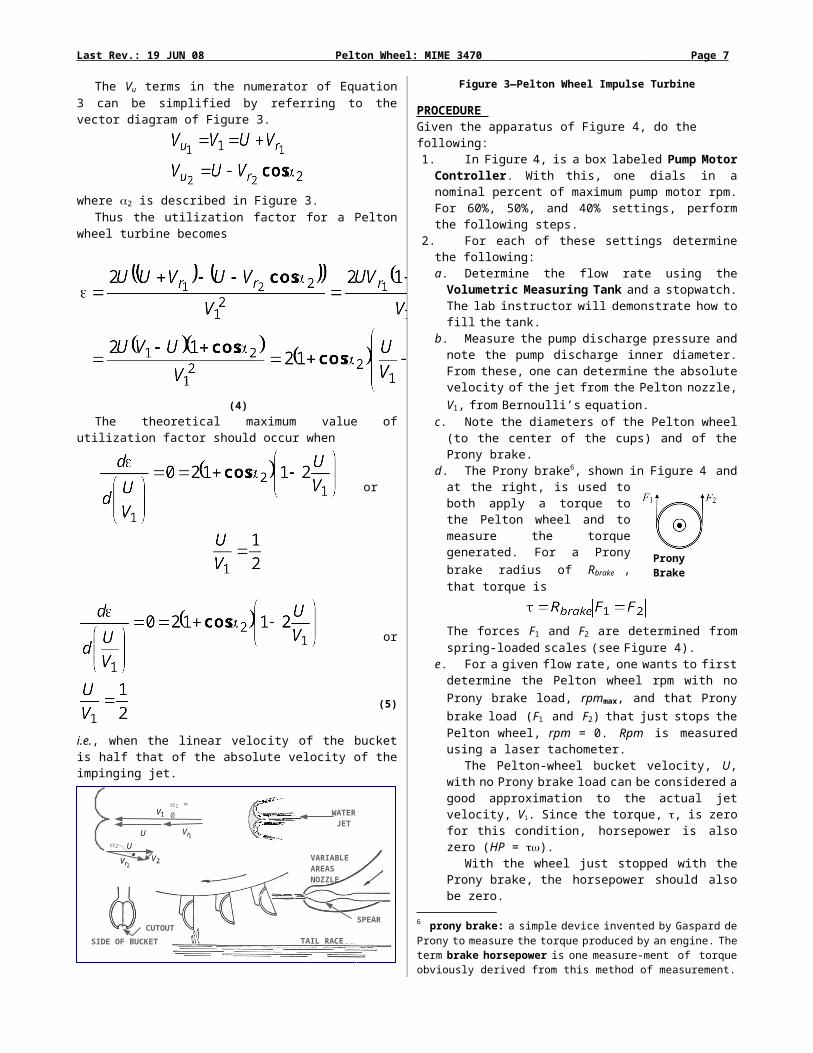
2. The Vu terms in the numerator of Equation 3 can be simplified
by referring to the vector diagram of Figure 3.
where 2 is described in Figure 3.Thus the utilization factor for a Pelton wheel turbine becomes
(4)The theoretical maximum value of utilization factor should
occur when
or
or
(5)
i.e., when the linear velocity of the bucket is half that of the absolute velocity of the impinging jet.
Figure 3—Pelton Wheel Impulse Turbine
PROCEDURE Given the apparatus of Figure 4, do the following:1. In Figure 4, is a box labeled Pump Motor Controller. With this,
one dials in a nominal percent of maximum pump motor rpm. For 60%, 50%, and 40% settings, perform the following steps.
2. For each of these settings determine the following:
5 Also known as zero-angle type.
TAIL RACE
SPEAR
WATERJET
SIDE OF BUCKET
VARIABLE AREASNOZZLE
2
1V
1rVU
U
2V2rV
1 = 0
CUTOUT

Last Rev.: 19 JUN 08 Pelton Wheel: MIME 3470 Page 6
a. Determine the flow rate using the Volumetric Measuring Tank and a stopwatch. The lab instructor will demonstrate how to fill the tank.
b. Measure the pump discharge pressure and note the pump discharge inner diameter. From these, one can determine the absolute velocity of the jet from the Pelton nozzle, V1, from Bernoulli’s equation.
c. Note the diameters of the Pelton wheel (to the center of the cups) and of the Prony brake.
d. The Prony brake6, shown in Figure 4 and at the right, is used to both apply a torque to the Pelton wheel and to measure the torque generated. For a Prony brake radius of Rbrake , that torque is
The forces F1 and F2 are determined from spring-loaded scales (see Figure 4).
e. For a given flow rate, one wants to first determine the Pelton wheel rpm with no Prony brake load, rpmmax, and that Prony brake load (F1 and F2) that just stops the Pelton wheel, rpm = 0. Rpm is measured using a laser tachometer.
The Pelton-wheel bucket velocity, U, with no Prony brake load can be considered a good approximation to the actual jet velocity, V1. Since the torque, , is zero for this condition, horsepower is also zero (HP = ).
With the wheel just stopped with the Prony brake, the horsepower should also be zero.
There is space on the data sheet for 10 rpms for each flow condition. In the procedure just above, the first and last rpms are defined. Now, divide the maximum rpm by 10 to determine the rpm interval such that the remaining 8 data points can be determined. Measure the Prony brake loads for each rpm.
Figure 4—Pump Performance Test Rig and Pelton Wheel
6 prony brake: a simple device invented by Gaspard de Prony to measure the torque produced by an engine. The term brake horsepower is one measure-ment of torque obviously derived from this method of measurement.
Pump and Motor CharacteristicsImpeller OD: 5” № of Impeller Blades: 6Type of Impeller: Open Type of Blades: Backward CurvingTorque Arm Length: 5” Motor Speed Range: 0-3000 rpm
Volumetric Measuring Tank
Sump Tank
Weight Hanger
Torque Arm Pump (see below)
Motor
Pelton Wheel BucketsPelton Wheel Buckets
Prony Brake Prony Brake
PumpMotor
Controller
PumpMotor
Controller
Spring-Loaded
Scale
Spring-Loaded Scale
Prony Brake
Last Rev.: 19 JUN 08 Pelton Wheel: MIME 3470 Page 7
CALCULATIONS A Mathcad is supplied below. Use the variable names already supplied in the object. At the bottom of this object is in the required format the student is to supply a summary of the 60%-rpm condition. This along with the required plot should be more than sufficient to evaluate the student’s work. One should be able to put all their Mathcad calculations on one sheet as shown in Figure 5.
The required plot is as shown in Figure 6. The data used to generate this plot is questionable so the actual shape of the curves is subject to change.
Figure 6— Sample Plot of CalculationsNote: The data used for this plot is questionable
Also answer the questions found in the Discussion of Results and supply a Conclusion(s).
REFERENCES1. Principles of Turbomachinery, D.G. Shepherd, MacMillian
Publishing Co., Inc, New York, 1956.2. Wikipedia, http://en.wikipedia.org/wiki/Water_turbine
http://en.wikipedia.org/wiki/Pelton_wheel http://en.wikipedia.org/wiki/Francis_turbinehttp://en.wikipedia.org/wiki/Kaplan_turbine
3. Engineering Fluid Mechanics, J.A. Roberson and C.T. Crowe, John Wiley & Sons, Inc., 6th Edition, 1997.
4. Turbines, J.B. Calvert, University of Denver http://mysite.du.edu/~jcalvert/tech/fluids/turbine.htm
5. National Inventors Hall of Fame http://www.invent.org/hall_of_fame/293.html
6. An Introduction to Energy Conversion: Turbo Machinery, Vol. 3, V. Kadambi and Manohar Prasad, Wiley Eastern, New Delhi, 1977
Google Books Result
ORDERED DATA, CALCULATIONS, and RESULTS (Mathcad object is reduced to 80%)
Figure 5—Example One-Page Calculation Sheet

Last Rev.: 19 JUN 08 Pelton Wheel: MIME 3470 Page 8

Last Rev.: 19 JUN 08 Pelton Wheel: MIME 3470 Page 9
DISCUSSION OF RESULTSWhat two features can be observed from the plot of the results?
Answer:
Why are the buckets designed so that 2 (see Figure 3) is a small, nonzero angle?
Answer:
What is the purpose of the cutout or notch at the periphery of the Pelton wheel buckets?
Answer:
What is the maximum ideal utilization factor for a Pelton wheel when 2 = 0?Answer:
Why must a turbine with nonzero degree of reaction have a rotor enclosed?
Answer:
Why does the relative velocity remain unchanged as the flow passes through a Pelton bucket?
Answer:
CONCLUSIONS
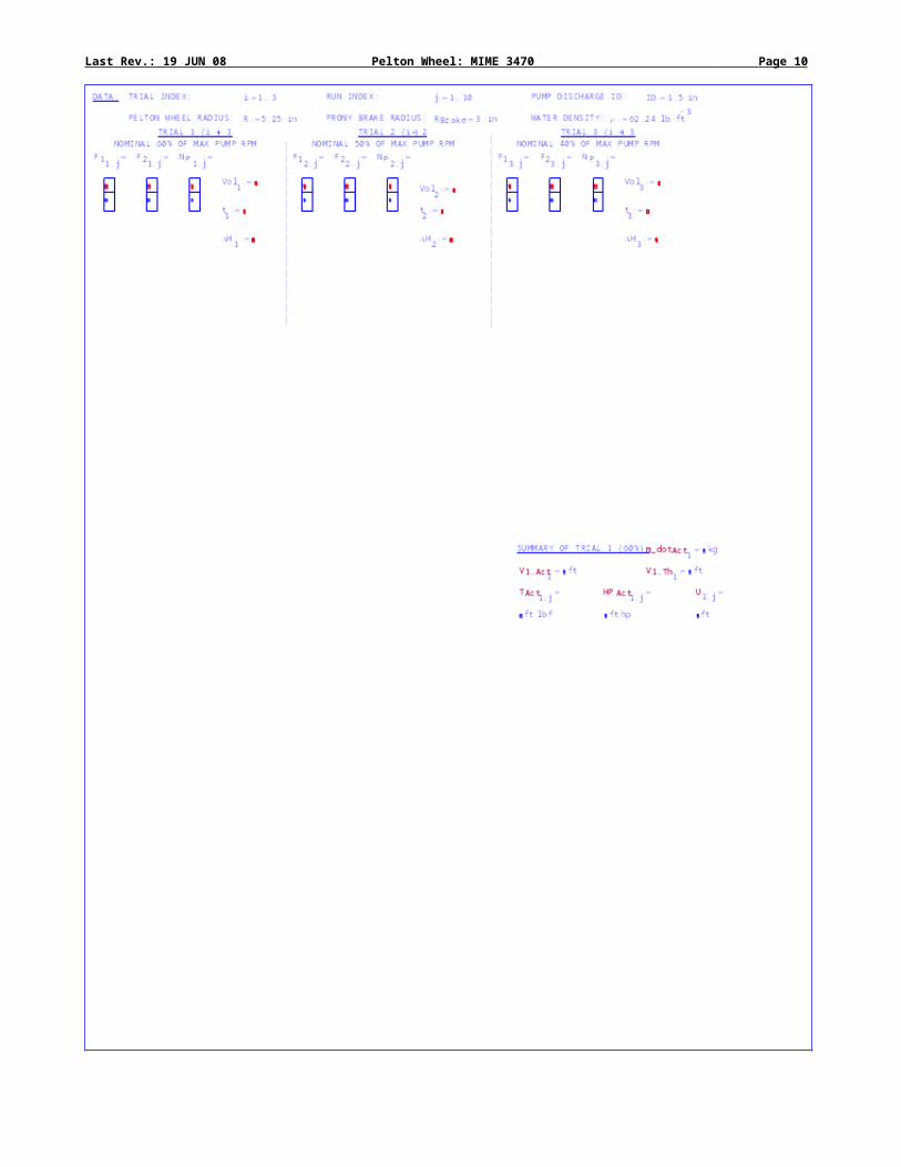
Last Rev.: 19 JUN 08 Pelton Wheel: MIME 3470 Page 10
APPENDIX—DATA SHEET
Time/Date: ___________________
Lab Partners: _______________________ _______________________ _______________________
_______________________ _______________________ _______________________
Particulars of the Apparatus: Pelton Wheel Radius, R: _________ ( ) Prony Brake Radius, RBrake: _________ ( )Pump Discharge Diam, ID: _____1.5 in___
Trial 1(i= 1)
Nominal 60% of
Max Motor RPM
PumpFlow Rate
Volume, Vol ( ) Trial 2(i= 2)
Nominal 50% of
Max Motor RPM
PumpFlow Rate
Volume, Vol ( )
Time, t ( ) Time, t ( )
Pump Discharge Gage Pressure, H ( ) Pump Discharge Gage Pressure, H ( )
Run, j
Prony Brake Forces
Pelton Wheel rpm Run, j
Prony Brake Forces
Pelton Wheel rpmF1
( )F2
( )F1
( )F2
( )
1 1
2 2
3 3
4 4
5 5
6 6
7 7
8 8
9 9
10 10
Trial 3(i= 3)
Nominal 40% of
Max Motor RPM
PumpFlow Rate
Volume, Vol ( )
Time, t ( )
Pump Discharge Gage Pressure, H ( )
Run, j
Prony Brake Forces
Pelton Wheel rpmF1
( )F2
( )
1
2
3
4
5
6
7
8
9
10