Pedibus Development - web1.eng.famu.fsu.edu
40
PEDIBUS DEVELOPMENT Final Design Report SPONSOR: RON GOLDSTEIN CAPITAL CITY PEDICABS FACULTIY ADVISOR: DR. PATRICK HOLLIS TEAM: ANDREW GALAN TEAM LEADER [email protected] JOHN HASSLER WEB DESIGN OFFICER [email protected] JAMES MCCORD FINANCIAL OFFICER [email protected] ONYEWUCHI EBERE LEAD M.E. [email protected]
Transcript of Pedibus Development - web1.eng.famu.fsu.edu

PEDIBUS DEVELOPMENT Final Design Report
SPONSOR: RON GOLDSTEIN CAPITAL CITY PEDICABS FACULTIY ADVISOR: DR. PATRICK HOLLIS TEAM: ANDREW GALAN TEAM LEADER [email protected] JOHN HASSLER WEB DESIGN OFFICER [email protected] JAMES MCCORD FINANCIAL OFFICER [email protected] ONYEWUCHI EBERE LEAD M.E. [email protected]

Executive Summary
Capital City Pedicab Company and its owner Ron Goldstein have entrusted the Florida
State University mechanical engineering department to aid and assist in their overall goal
of setting up a manufacturing station of fully operating Pedibus system in the southeast
region of the United States. The development of a Pedibus transportation vehicle involves
various amounts of mechanical components and evaluations. As the first semester is
coming to an end, the development of this project is appropriately on schedule. The final
design of the Pedibus has been developed and analyzed. The production of the road-ready
prototype is ready to begin. Selected material and manufacturing options have been
budgeted to make the safest and most cost effective vehicle. Being in immediate contact
with the sponsor and positive communication has allowed for the construction of the
vehicle prototype to begin in the upcoming semester and hopefully meet the personal
goal date of completion.

Table of Contents
I. Acknowledgment pg. 1
II. Project Overview pg. 1
A .Project Goal pg. 1
B. project Objective pg. 2
C. Constraints pg. 2
III. Design and Analysis pg. 2
A. Function Analysis pg. 4
B. Design Analysis pg. 3
C. Dynamic Analysis pg. 10
IV. Risk and Reliability Assessment pg. 17
V. Detailed Design and Design for Manufacturing pg. 17
VI. Procurement pg. 18
VII. Communications pg. 19
VIII. Conclusion pg. 19
IX. Environment and Safety Issues pg. 20
X. Future Plans pg. 20
XI. Budget and Resources pg. 20
XII. References pg. 21

1
I. Acknowledgement
We wish to acknowledge the following for the respected support and guidance thus far
into the senior design project development:
The Florida State University – Florida Agricultural & Mechanical University
School of Engineering for allowing us the opportunity to work with external
companies to gain project development experiences.
Instructor Dr. Kamal Amin for evaluation and positive feedback. Faculty
Advisors Dr. Chiang Shih and Dr. Patrick Hollis for helping with problem
solutions referring to the development of this project.
Special acknowledgement is given to Capital City Pedicabs, and in particular
CEO, Mr. Ron Goldstein, for providing us with the sponsorship and ability to
provoke on such a rewarding development project.
II. Project Overview
The overall purpose through this development project is to aid in the assistance
for Capital City Pedicabs is to start the production and manufacturing of Pedibuses in the
southeast region of the United States. To do this the purpose of this semester has been to
develop concept ideas and analysis to review with the sponsor and lead to the
construction of a fully operating road-ready Pedibus. The beginning process of this
project dealt with structural and aesthetic concept designs. Kinematics and ergonomics
were taken into account, as well as the budgeting and selection of necessary materials and
items to construct the prototype.
A. Project Goal
Developing and manufacturing a fully functional prototype pedibus by the end of
April 2014, is the priority goal for the project. The development of the prototype will
provide information about dynamic and structural design, along with cost and
maintenance recommendations. The Pedibus is to be eco-friendly and safe to the public.
It is expected to be efficient enough that it can be powered by only two people.
B. Project Objective
The objectiv of this project is to design and build a multi-passenger prototype
vehicle that is powered by pedal inertia. The prototype will be used as a guide for the set
up of a Pedibus manufacturing station. The design is to take safety and maintenance
considerations into account when considering every component. There are several
parameters that had to be met to reach the final goal. These included:

2
Developing the size of the vehicle based on the number of desired
passengers and relative price points of the material and construction
costs.
Designing an appropriate frame structure that is lightweight and has
optimal strength.
Design the linkage system that will be connected to the drive shaft, to
integrate a power drive system.
Decide on the type of steering and braking to use on the vehicle that
will provide a safe, comfortable ride.
Decide on tires and wheel to reduce unwanted frictional forces
Integration of a power assistance motor and battery to power vehicle
and safety lights.
C. Constraints
Several constraints have been altered from the initial design of this project with
the approval of the sponsor. Constraints experienced this semester have been overcome,
but are still necessary to list for means of discussion. They are:
Starting budget of $2,000 – Current budget set at $5,000
Low manufacturing cost to validate for cost effective reproduction
The weight of the vehicle traveling up an inclination or without
passengers will require motor power assistance.
Maintenance has to be minimal, simple, and inexpensive.
State automotive street laws have to be considered and applied to
secure the safety of the public.
III. Design and Analysis
The development can be broken down into three main subcategories; structural,
steering and braking, and power linkage. These are the main components that required
numerous conceptual designs and analysis to ensure to cheapest, lightest, and safest
Pedibus.
A. Function Analysis
The Pedibus is developed around the idea that it is an eco-friendly, pedal inertia powered
entertainment vehicle. The passengers are assigned to individual peddling stations and as
the peddles move and rotate the operating components the vehicle will begin to move;
much like a common bicycle. The proceeding section will discuss the functionality of
each major subcategory.
i. Structural Frame
The primary task of the frame is to tie together all of the separate
components of the vehicle in a safe and secure fashion. Considerations taken into
account in design of the frame are strength, safety, weight, and maintenance.

3
Strength is the most pivotal aspect. The frame needs to be strong enough to
withstand forces larger in magnitude than what is to be expected in normal
operation. Primarily, the loads will be downward forces, but lateral forces as well
as acceleration and deceleration forces are taken into account and planned for.
ii. Steering and Braking
The control operation of the Pedibus has to be safe and simple to provide
ease of maintenance and control. The steering system is responsible for turning
the wheels either left or right depending on the orientation of the wheel
determined by the central driver. As the driver rotates the steering which through
a gear set will translate the rotational motion into a linear transitional motion.
Once the Pedibus is in motion, determining the best stopping method has to be
taken into great consideration to apply the best possible public safety. Normal
automobiles have brakes that are used to reduce the speed of a vehicle to come to
a complete stop. The same idea goes into the stopping of the Pedibus. As force is
applied to the brake pedal by the driver the rotor will begin to slow down until all
kinetic energy is lost and come to a complete stop. Both braking and steering are
going to be located at the front central driving station, and not at the pedaling
stations, to ensure that the proper steering and braking applications are made.
iii. Power Linkage
The power linkage of the Pedibus system works under the principle that
the passengers input the power required to move the vehicle. This power input is
accomplished by the passengers pedaling at the
pedaling station. The pedaling power input by all
passengers is then converted into the motion of
the Pedibus. Early in the semester the Pedibus
team researched how other Pedibus
manufacturers had accomplished this
transmission of power from the pedals to the
wheels of the vehicle. Viewing the information
posted on several different Pedibus manufacturers’
websites it was observed that all existing
Pedibuses have the pedaling power input to a
central drive shaft. This drive shaft is connected to
a rear differential from an automobile. After
exploring other options through the course of the
semester the Pedibus team has decided to implement this functional design in the
vehicle we are developing. Figure 1 is a simple diagram of how our team initially
visualized the linkage between the pedaling stations, drive shaft, and rear axle of
the vehicle.
B. Design Analysis
The design of the prototype is the back-bone to the Pedibus development.
Multiple concept design and errors had to be overcame to provide the most simple and
Figure 1. Initial Power Linkage Design

4
safest design. The design of a prototype is the stepping stone for possible production,
since it is typically the first thing a company brings a consumer to review. The designs
that will be discussed have been analyzed and chosen for the ease of maintenance and
reliability.
i. Structural Frame
The weight of the frame is a large factor in how much power input each of
the passengers of the Pedibus will need to input to accelerate and maintain its
velocity at the desired cruising speed of 5 mph.
Due to the tourist friendly nature of the
vehicle, an enjoyable experience for the
passenger is necessary. The lighter the frame
the more enjoyable the experience for the
passenger. In an effort to minimize the weight
of the frame as much as possible, while still
retaining strength, different materials were
explored. The primary materials taken into consideration were steel and
aluminum. Steel is a very strong material and monetarily fits within the budget. It
is roughly twice as strong and three times as heavy as aluminum. The initial lower
frame design composed of only steel and is shown in figure 2. This frame was
made of 2x2 rectangular tubing with wall thickness on 0.125 in. It was 110 ft of
material in all, the price of the raw material was sourced at around 900$, and it
weighed in at 460 lbs. This was far too heavy, as none of the drivetrain,
suspension, steering, or bicycle components are included in that weight.
It is not a question whether or not this steel frame is strong enough for our
application, as many of the Pedibuses today use a very similar all steel cage
construction, but since our Pedibus is going to be crawling the streets of our very
hilly college town, opportunities to cut weight by a more efficient frame design
were explored.
A frame consisting of all
aluminum would be ideal, though the
amount of extra aluminum support to
counteract the drooping of the frame across
the span between the front and rear tires
would be so thick with the struts, supports,
and cross members so much that it would
not allow for much room for maintenance of
drivetrain components, which is not optimal.
This issue led to exploring the idea of a
steel and aluminum frame. Consisting of
two main steel rectangular supports spanning from the front end components to
the rear axle supporting the weight load of the passengers and aluminum frame
which will be rested atop of the steel beams, shown on the figure 3.
Figure 2. Initial all steel frame design
Figure 3. Steel support beams for aluminum cross members

5
When consulting with an experienced welder regarding the design of the
crossmember the suggestion was made to extend the side beam of the cross
member to increase the overall strength of the seat mount. The adjusted
crossmember geometry is shown in figure 4.
The considerations for the seat mount on the crossmember to facilitate
implementation of mass produced bicycle seats that the sponsor’s bike mechanic
can source for a lower price. This includes a 1in
diameter seat mounting hole that is the general
standard for bike seat posts. This will also
provide versatility in the design such that if a
smaller child will be sitting at a pedaling station,
a childs bucket seat can easily be mounted in
stead of a standard bike seat.
The mounting of the bicycle pedals,
crank, and gears to the cross member will be
accomplished by two mounting holes on each
side beam of the cross member. The entire
assembly of the crank mounted onto the crossmember is shown in figure 5.
Making the bike components detachable from the crossmember will make them
much more accessible to the bike mechanic who will be maintaining the pedibus,
the detachable portion will include the pedals, sprocket, and the free wheel.
With the design of the cross member finalized the issue of how to attach
the Aluminum cross member to the steel frame is made pertinant. The mount
needs to incorporate resistance from the cross member from tipping forward or
backward which will be the largest force that the mount will need to resist.
Keeping the crossmember from moving laterally will be a much smaller force to
prevent from occuring. This is an aspect of bracket design that can be capitolized
on, since drilling and removing any material from the aluminum can weaken the
material and make the FEA analysis less accurate.
The Proposed design of the bracket to
fasten the Aluminum cross members to the steel
support struts is shown in figure 5, the primary
objective of the bracket is to prevent a tipping
moment, as well as to secure the aluminum to
the lower steel beam. Considerations taken
during the design of the bracket are the material
of the bracket, steel, and an effort to minimize
any drilling into the aluminum, which would
jeaprodize structural integrity of the upright
within the crossmember. The bracket will be
secured to the lower steel beam with nut and
bolt through the predrilled 3/8 inch holes in the
steel beam and the bracket. Washers and lock
Figure 4. Finalized cross member geometry
Figure 5. View of bicycle crank and support bracket mount on cross members.

6
washers will be used to ensure the bolt will not loosen with vibration. Securing
the crossmember to the bracket will be accomplished in a similar method to how
the bracket was secured to the steel frame,
except the predrilled holes through the
aluminum and bracket will be 1/16 inch. The
holes in the aluminum bracket are primarily
preventing lateral translation so they do not need
to be as large as the holes in the steel beam, as
those mounting holes will be preventing the
tipping moment of the crossmember which will
be a far greater force. To further prevent tipping
moments of the crossmember, a triangular
flange will be preventing anybending of the
crossmember mounts. The finalized bracket design is shown in figure 6.
The sponsor of this project wanted to have an adjustable bar top height to
accommodate different sized riders. This was achieved by four primary posts
protruding through the walking platform above the crossmembers. The posts are
mounted and welded to the top of the frontmost and rearmost crossmembers and
are linked at the top at corresponding mounting locations of the umbrella top,
where gusset plates will be implemented to prevent any sway within the bar posts.
The bar will be adjustable upon these posts by a pin and sleeve system
where various predrilled holes can be used as different height mounts for the
bartop. The material for the bar top will be a hard wood, similar to that of bar tops
in restaurants or bars. it will be treated to be
moisture resistant, but it will not be as thick or
heavy. For safety the bar top will have handle holes
cut into it at corresponding locations for each
passenger. The aluminum frame will wrap around
the front of the pedibus, and will be mounted to the
lower steel support via brackets and will be welded
to the front two bar posts to further enhace the
strength of the bar posts, though the weld location
will be below the lowest bar height adjustment
setting as to not interfere with the bar top
adjustability. A picture of the front aluminum
structure is shown in the figure 7.
ii. Steering and Braking
When the Pedibus is traveling and moving along the road, it is important
to know the design behind its operating and controlling components. In steering
and braking there are various aspects that decide whether a system is desirable or
not. For steering there a two basic designs that were taking into consideration.
The rack-and-pinion steering system and the recirculating-ball steering system.
Both systems are reliable and simple, and after large amounts of research the
rack-and-pinion steering was chosen to be the best system for the prototype
Figure 6. Finalized bracket geometry.
Figure 7. View of front driving station

7
design. Recirculating-ball steering is often used for heavier vehicles that required
gear reduction to reduce the amount of frictional forces for easier steering. In the
case of the Pedibus, the unloaded total weight of the vehicle is relatively light to
that of a normal automotive vehicle and does not involve complex gear reduction.
Rack-and-Pinion Steering
Mostly common in earlier date cars and currently common in most
automotive and other Pedibus designs. The rack-and-pinion is the most simple
gear set used in steering control and is
typically enclosed in a metal casing tube.
Referring to figure 8 it is noticeable that a
pinion gear, located at the bottom end of the
steering shaft, is connected to a horizontal
gear rack. As the orientation of the steering
wheel changes, due to driver commands, the
pinion gear will rotate in a fixed position.
The interactions with the gear rack will
convert the rotational motion of the pinion
gear into transitional linear motion of the rack from left to right. At both ends of
the rack is attached a tie rod. These tie rods conjoin to the steering rods located at
the upright or spindle of the wheels. This series of components allow for the
driver to change the direction of the wheels with ease and have complete control
of the Pedibus.
In order to secure the safety of the vehicle, the passengers,and the public
the braking system implemented has to be very tuned and observed in detail for
best selection. Most cars today use disc brakes in the front because of the
reliability and simplicity of the system. Once researched had been concluded, it
was found that disc brakes would also be the best application for the prototype
vehicle.
Disc Brakes
The braking system has to be able to bring the loaded assumed 3000lb
weight of the Pedibus to a complete and safe stop, for both the driver and
passengers. Disc brakes consist of three main instruments: the rotor, the calipers
and brake pads, and the fluid brake lines. As the brake pedal is compressed by the
driver and force is applied the push rod begins
to extract braking fluid out of the master
cylinder. Once the fluid has left and travels
through the hydraulic brake lines into the
secondary cylinder. With constant pressure
from the fluid the piston, located at the
secondary cylinder, conforms and compresses
towards the rotor, seen in figure 9. The piston
itself does not come into contact with the
rotor, instead there are calipers that are used
Figure 8. Rack-and-Pinion steering system
Figure 9. Completed disc brake and frontal view.

8
for contraction. On the inside of the calipers are brake pads on each side of the
sidewalls of the rotor. As the brake pads become tighter around the rotor, the
kinetic energy begins to convert into heat. The reason for disc brakes being so
reliable is that they only respond to the amount of force applied by the driver,
securing a safe stopping method.
iii. Power Linkage
Picking the functional design was made simple by looking at the websites
for other Pedibus manufacturers and observing the general principals by which
their Pedibuses are powered. What isn’t made clear on the manufacturer’s website
is how they link the pedaling power from the passengers to the drive shaft. One
problem that is immediately apparent with this design is that passengers on
opposite sides of the Pedibus can’t both pedal forward. To address this issue we
developed a number of different designs for the linkage between the pedaling
station and the drive shaft. Ultimately the team decided that flipping the chains on
one side of the Pedibus as they connect to the drive shaft. By flipping the chains
the rotational input to the drive shaft is effectively reversed as seen in figure 10.
Figure 10. Linkage between the pedaling station and drive shaft
The benefits to this design are that all passengers can pedal forward and
that it requires very few additional components over other design concepts.
Slightly longer lengths of chain will be required for all the pedaling stations on
one side of the Pedibus to account for the longer distance required to cross the
chains. The negative aspects of this design are minimal. Without adding some
additional parts to keep the chain links from rubbing against each other as they
cross the life span of the bike chains will be reduced. To counter this potential
reliability issue a set of pulleys will be installed to guide the chains around each
other. A 3D model representation of what this would look like on the final
Pedibus prototype can be seen in figure 11.
Figure 11. Pulley placement on cross member

9
Figure 14. Keyed drive shaft assembly
In the initial visualization of the power linkage it was believed that the
pedaling stations would have to be offset from each other so there would be room
for all the gears on the bike shaft. This configuration can be seen in figure 1. After
designing the frame it was decided that the pedaling stations could be attached to
the same cross member support and the pedaling gears and chain installed on the
cross member as seen in figure 12. This layout for the pedaling mechanism allows
for a less complicated assembly of the Pedibus.
The drive shaft itself will be ¾ inch cold rolled steel rod. The drive shaft
will be connected to the structural frame of the Pedibus by pillow blocks which
will be bolted to the undersides of the four cross members that make up part of the
structural frame of the Pedibus. Figure 13 gives a better reference as to where on
the Pedibus these pillow blocks will be installed. It can also be seen from figure
14 that the drive shaft will be keyed so that the bike gears can be attached to the
drive shaft without having to be welded onto the shaft. The key between the drive
shaft and the bike gear hub keeps the bike gears rotation locked to that of the
drive shaft. Two collars with set screws are installed on either side of each gear so
that the gear doesn’t slide on the drive shaft. This allows for easier maintenance
of the Pedibus in that if one of the gears breaks the collars and gear hub can be
removed, the gear slipped of the shaft, and a new one slipped back on in its place.
It is important to note that if the middle gear breaks all gears between that gear
and the end of the drive shaft will also have to be removed which is much easier
to do with gears keyed to the drive shaft than with gears welded to the drive shaft.
Figure 12. Top view of cross member with bike components.
Figure 13. Bike gear and pillow block assembly

10
The drive shaft is connected to a repurposed rear axle of an automobile.
The driveline input for the differential has a larger diameter than the ¾” driveshaft
it is being connected to. A piece of A36 cold rolled steel round stock 2.5” in
diameter will be machined to fit inside the driveline of the rear differential and
will have a ¾” hole bored through it to fit the drive shaft. The pieces will then be
pinned or welded together to bridge the connection between the drive shaft and
rear differential. The rear differential being sought after is the rear end of a
Toyota T100 truck. The Toyota T100 has a rear differential gear ratio of 3.08:1.
The differential gear ratio is an important figure to know for calculating the bike
gear ratios between the drive shaft and the pedaling stations as will be explained
in that portion of the analysis section later in this report. The rear axle transmits
the power input by the driveshaft to the rear tires of the Pedibus.
The tires chosen for this vehicle were chosen based on their coefficient of
rolling resistance. As is explained in further detail in the analysis section of this
report the dominant force that must be overcome to maintain the desired cruising
speed of the Pedibus is the force of rolling resistance. The easiest way to
minimize the force of rolling resistance is to pick a tire with the lowest coefficient
of rolling resistance. The Michelin Symmetry P225/60R16 has a rolling resistance
coefficient of 0.0065 making it one of the lowest rolling resistance full sized tires
on the market. The tire fits a 16” rim and has a total inflated diameter of 26”.
C. Dynamic Analysis
Knowing the design and skeleton behind the development of the Pedibus only
deals with the functional and aesthetic image of the vehicle. The real success of the
project is due to the mathematical and computer dynamic analysis that went into every
component. Knowing characteristic properties and limitation, eliminates room for error
and undesirables results.
i. Structural Frame
The design of the cross member was a dialing in process, FEA analysis was used
to ensure that the design of the cross member would complement the lower steel
beams in a fashion which yielded the
maximum strength possible. The
initial design for the incorporation of
an aluminum and steel frame yielded
less than comforting FEA static load
analysis results. Shown in figure 15 is
the results of the static load analysis
of the first proposed design of the
cross member. The analysis was
performed with a uniform distributed
load of 1000 lbs. across the diamond
plate aluminum platform that rests Figure 13. FEA analysis of initial aluminum cross member design

11
atop the 4 cross members and an additional load of 300 lbs. was placed at the seat
mounts of each of the 8 pedaling stations. The areas of light blue are stresses
above the yield strength of aluminum and the blue areas are areas of stresses that
are near the yield stress of aluminum. The results of this test were concerning and
the design of the aluminum cross member was modified and reanalyzed.
The modifications made to the
cross member include positioning the
cross member uprights above the steel
beams and pulling the side beams in
closer toward the steel supports. As
shown in the static load analysis of
the frame after the adjustments were
made to the cross member in figure
16, the areas of stresses have been
greatly reduced and there is no
stresses above the yield strength of
aluminum present.
ii. Steering and Braking
With the decision to use rack-and-pinion steering the Pedibus is going to
have an automotive vehicle steering feel. The driver will turn and control the
vehicle by means of a common steering wheel. Since the Pedibus is made as an
entertainment console and is not going to be operating at high speeds, the turn
radius is going to have to be able to make tight corners. The sharpness of the turn
and responsiveness is due to the pinion diameter and gear rack length. The
maximum turning angle of a normal rack-and-pinion steering is at about 60
degrees. This large angle allows the Pedibus to take tight corners when the
steering wheel is rotated fully.
Figure 14. FEA analysis for modified cross members
Figure 15. Analytical graph of turning radius vs. turning angle

12
Looking at the graph in figure 17, It can be observed that as the turning angle
begins to increase, in degrees, that turning radius reduces as a result. This is a
normal characteristic of steering and proves desired results. A balance equation
was used to find the opposing lateral forces that may be applied during cornering.
Detailed mathematical analysis and equations are performed in the appendix.
Once the Pedibus is in motion, the next concern is bringing it to a safe and
complete stop. The braking force is applied by the front central driver and
controls the distance that the Pedibus will come to a stop. An assumption of the
driver weighing around 200 lbs. was made to give an assumed applied braking
force of between 0 lbf when no force is applied, to 100 lbf when maximum force
is applied. Forces that had to be overcome, and are detailed in the appendix,
included: the brake pedal, brake pads, calipers, friction of rotor, and fluid pressure
forces, as well as the tire forces. A graph was compiled, as seen in figure 18 that
shows if the assumed driver were to apply any force greater than 40 lbf. that the
Pedibus will stop within one foot. Also we can conclude, the slower and softer the
driver exerts force to the brake pedal the slower that rate of stopping as well. The
results put confidence into the brake system chosen as it provides a safe and
efficient stopping method.
iii. Power Linkage
Power Input Requirements
A question of central importance when designing a human powered
vehicle is, “how much power must be generated to move the vehicle at the desired
speed?” In the case of the Pedibus it is important to know how much power each
passenger must generate under different scenarios. The amount of power a person
can generate varies greatly between people. Some general numbers of what
Figure 16. Analysis of stopping distance vs. driver braking force

13
people can generate are given as reference in table 1. The powers calculated in
table 1 are based on average output for one hour of performing the exercise
activity. Based on these numbers, and some experimenting on a cycling machine
at the gym, it was determined that a constant power output of less than 60W was
desirable so that powering the Pedibus was not too tiring.
Table 1. Average Human Power Generated for Activities
ACTIVITY AVERAGE POWER OUTPUT
For 1 Hour (Watts)
Walking at 3mph 30W
Average person bike racing 120W
Regular cyclist racing 220W
Professional cyclist racing 300W
Lance Armstrong racing 400W
Analysis was done on the power requirements to maintain a cruising speed
of 5mph and to accelerate to 5mph from rest. Analysis of the power required per
passenger based on total number of passengers and traveling velocity will also be
discussed.
Maintaining cruising speed
The desired cruising speed for the Pedibus is 5mph. To maintain a speed
of 5mph the forces that must be overcome are the force of drag, rolling resistance,
and the force required for any change in elevation. If it is assumed that the
Pedibus is traveling on level ground and there is no change in elevation then the
force of drag and rolling resistance are the only forces. Equation (1) is the
equation for calculating the drag force on the Pedibus at a given speed. Assuming
is our desired cruising speed of 5mph and the coefficient of drag ( Cd) is
assumed to be 1.05 ( the drag coefficient of a flat plane normal to wind velocity)
The force of drag on the Pedibus is found to be 8 N. Using Eq. (2) this represents
a power input of about 17W.
(1)
(2)
The force of rolling resistance can be calculated using Eq. (3). The
coefficient of rolling resistance (Crr) of the tire chosen for use on the Pedibus is
0.0065. All calculations for rolling resistance were made assuming that the tire
would have a higher Crr of 0.01 when supporting the weight of the Pedibus and
passengers. With this assumed value for Crr and an assumed loaded weight of
2750lb (weight of Pedibus and eight 250lb passengers) the force of rolling
resistance was found to be 123N. To maintain a speed of 5mph it takes 275w of
power to overcome rolling resistance. From these values it can be seen that rolling

14
resistance is the dominant resistant force at the velocities the edibus is designed to
travel at. If all passengers are pedaling with equal power input (equal torque on
the pedals at the same rotation speed) each passenger would need to generate
37W of power to maintain a traveling speed of 5mph.
(3)
Reaching Cruising Speed
Equation (4) represents the sum of the forces acting against the Pedibus
while accelerating. The force of rolling resistance (Frr) and the force of drag (Fd)
have already been calculated. The force of acceleration (Fa) is calculated with
Eq.(5) . There is no acceleration rate requirements for the design of the Pedibus.
The Pedibus team determined that if the Pedibus starting from rest could reach a
cruising speed of 5mph 20 seconds that would be sufficient rate of acceleration to
accomplish all the need of the Pedibus. This represents an acceleration of 0.367
.
The power required to achive this acceleration varies with traveling velocity.
Since acceleration to cruising speed represents such a small portion of the
traveling time the Pedibus teams analysis was focused on the maximum power
input required to reach 5mph if accelerating at a constant rate of 0.367
as
opposed to average or total power input required. The max power input required
to move the Pedibus from rest to 5mph can be determined using Eq. (6). The
maximum power required to accelerate the Pedibus was determined to be 604W.
This represents a power input of 75.5W per passenger. While this is above our
desired power output of 60W it is for a very short period of time and is thus
acceptable.
(4)
(5)
( ) (6)
Traveling with less than full capacity
An objective of this design project, set at the beginning of the semester, was that
the Pedibus be able to be power by as few as 2 passengers. The equations
mentioned previously in this section were used to generate fig. 19, a graph of the
power required to maintain 5mph based on number of passengers, and fig. 20, a
graph of the power required to accelerate to 5mph based on number of passengers.
From these graphs it can be seen that, while it will require more than double the
power, two passengers could accelerate the Pedibus to 5mph with 168 W of
power input each, and could maintain it at that speed with 83W of power input
each. While these power inputs are higher than the ideal limit of 60W per
passenger they are low enough that two people in average shape can power the
Pedibus for at least an hour before tiring.

15
Figure 17. Watts per Passenger to maintain 5mph Velocity vs. Number of Passengers.
Figure 18. Maximum Power Required per Passenger to Accelerate from Rest to 5mph in 20 seconds
Traveling up an inclined slope
All analysis on the power requirements for moving the Pedibus discussed up to
this point in the report have assumed the Pedibus was traveling on level ground.
The topography of Tallahassee is more like that of southern Georgia than it is like
that of the rest of Florida in that it has a number of significantly sized hills.
0.0
20.0
40.0
60.0
80.0
100.0
120.0
140.0
160.0
1 2 3 4 5 6 7 8
Wat
ts R
equ
ired
per
Pas
sen
ger
# of Passengers
Watts per Passenger to Maintain 5mph Velocity Vs Number of Passengers
0.0
50.0
100.0
150.0
200.0
250.0
300.0
1 2 3 4 5 6 7 8
Wat
ts R
equ
ired
per
Pas
sen
ger
# of Passengers
Maximum Power Required per Passenger to Accelerate from Rest to 5mph in 20 seconds

16
Because of this when designing a vehicle to be operated in this area it is not
reasonable to assume the vehicle will travel on level ground. Assuming an incline
of 7% Eq. (7) can be used to calculate the additional force acting against the
Pedibus as it is traveling uphill which was determined to be 931N. This is more
than double the force acting against the Pedibus as it travels on level ground and
represents an additional power requirement per passenger of 300W per passenger.
This mean each of the eight passengers will have to generate 340W of power to
climb a 7% incline at 5mph. Referencing table 1 it is clear that very few
passengers who travel the Pedibus will be able to generate that amount of power.
A slower travel speed is required for traveling uphill. Figure 21 is a graph of
power requirement per passenger based on the vehicle velocity being maintained.
From the graph it was determined that while traveling up an incline the vehicle
speed will have to be reduced to 1 or 2 mph unless electric motor assistance is
used.
( ) (7)
Figure 19. Power Required to Ascend 7% slope Vs Velocity
Passenger pedaling RPM Analysis
Not only is it important that the passengers have a reasonable required power
input to move the Pedibus, it is also important that the passenger pedaling rpm
also be reasonable. Comfortable pedaling rpm are between 50 and 80 rpm for
bicycling and will serve as the range of possible pedaling speeds for the Pedibus.
With a tire diameter of 26” the wheels of the Pedibus rotate at 65rpm while the
Pedibus is traveling at 5mph. The 3.08:1 gear ratio of the rear differential means
0
50
100
150
200
250
300
350
1 2 3 4 5
Wat
ts R
equ
ired
per
Pas
sen
ger
Pedibus Velocity (mph)
Power Required to Ascend 7% slope Vs Velocity

17
the drive shaft spins at 200rpm which is too fast a rotation speed to achieve at the
pedaling station. To correct this issue a 3:1 gear ratio will be used between the
pedaling station and the drive shaft (the gear at the pedaling station being 3 times
bigger than the one on the driveshaft). This gear ratio makes the rpm at the
pedaling station 66rpm which is in the middle of our comfortable pedaling range.
The variable that govern this ratio are the tire diameter and the rear differential
gear ratio. If wither of these values are changed the gear ratio between the
pedaling station and drive shaft will have to be adjusted.
IV. Risk and Reliability Assessment
Public safety and eco-friendly are two of the most stressed parameters of the
Pedibus development project. There are always uncertainties and possibilities of risk that
may arise and it is one the development goals to eliminate as many of these factors as
possible. The factors that can affect the public or vehicle safety will be listed below, but
its important to discuss the procedure behind deciding which are the most important to
evaluate. If the situation were to injure the passengers, surrounds public, or environment
then precautions must be taken to reduce to chances. Certain scenarios, but not limited to,
may be:
The weight of the vehicle effecting pedal power after long periods of time.
Without the use of seatbelts, the probability of a passenger falling has
increased.
Pedaling the vehicle up an inclination without requiring maximum effort
Frictional forces due to road and tire conditions
Environmental conditions that may affect to condition and wear of individual
components
Much observation, evaluation, and mathematical analyzing has been conducted to ensure
to construction of a safe a reliable Pedibus prototype. Reliability not only protects the
public but also provides reinsurance for possible reproduction of the developed prototype.
V. Detailed Design and Design for Manufacturing
After much evaluation and analyzed data, the final design for the road-ready Pedibus
prototype has been decided and is ready for manufacturing. The complete vehicle shown
in figure 22 will contain all features previously mentioned and discussed as well as all the
road safety features. The prototype contains a
central drive shaft, along with all other
mechanical components (pedals, chain links,
wheels, steering, suspension, etc.) and also a
front driving station. For investor reasons
there Pedibus will have room for advertising
and open space in the rear that will allow room Figure 20. Complete assembly of Mustang IFS II front beam axle.

18
for an extra bench seat, or ice cream cooler, and even a beer dispenser if desired. The
front axle will also be bought as a unit, specifically the Mustang IFS II, seen in figure 22.
This will allow for easier assembly and ensure all the parts fit and operate properly.
VI. Procurement
The sponsor Ron Goldstein has offered to purchase all of the components to avoid
the delay of ordering components through the engineering school. Dr. Amin advised the
team have the sponsor purchase components for this very reason. The aluminum and steel
will be acquired by ordering online from www.discountsteel.com
The front end of the Pedibus will be
ordered from http://www.fulltiltstreetrods.com.
It will include the brake calipers, rotors, wheel
hubs, suspension and steering system all in one.
The assembly will cost $1200 with free
shipping off of eBay. Once received, it can be
welded directly to the steel portion of the frame.
The steering wheel will be sourced from eBay
Figure 22 All the components included in the front beam assembly
Figure 21. Scale model of the road-ready Pedibus prototype design

19
as well. The linkage rods and universal joints connecting the steering wheel to the rack
and pinion steering will be sourced from McMaster-Carr. The brake pedal and master
cylinder will also be sourced from eBay.
The rear differential of the Pedibus will be obtained by visiting the local pick and
pull and using an angle grinder and cutting the U-bolts that hold it onto the box springs of
the Toyota T-100.The system which will be harvested and the differential including the
wheel hubs will be around $140.
The pedaling stations and bike components, such as bike seats, pedals, pedal arms,
sprockets, and chain, and overlap pulleys will be sourced by a cooperating bike mechanic
who owns his own shop and will be able get a discount wholesale price Most of these
components have already been picked and sourced. The bike mechanic has advised
waiting until after the holidays until ordering; as there is always a price drop on bike
components after the holidays.
The tires and wheels will be sourced and purchased locally, the actual choice on
rim style has not been made and it is up to the sponsor to pick his preference. Although it
is possible that the hubs on the rear axle do not have the same lug pattern as the front end,
this is not an issue. Team members are aware of this and it will be possible to procure the
same design of wheel with a different lug pattern as to retain aesthetic consistency. The
tire size has been chosen, as well as tire model. The tire that was picked was chosen due
to its low rolling resistance.
VII. Communications
The success of this project until this point has been due to the consistent and
positive communication between the sponsor and team members. Biweekly meeting with
the instructor and faculty advisors have allowed for positive and guiding feedback that
promoted advancements in the development stages of the project. Communications have
also been made with outside resources for individual part sourcing and construction
guidance. We hope as a team, to keep to strong communication and cooperation to
resume into the following semester not only among members, but also with the sponsor,
instructor, and advisors as well.
VIII. Conclusions
The midyear progress in the design of the Pedibus development has met all the
expectations set at the beginning of the semester by the team and sponsor. The vehicle
now accommodates the request for variable seating heights to allow wide age group. The
weight and strength of the vehicle needed to be light yet strong under pressure. After
evaluating multiple materials, a combination of both aluminum and steel was chosen for
the structural frame. This combination not only provides a low cost, but also a high
strength to weight ratio to confirm maximum strength and light weight. The reduction
being 26% less than the initial all steel weight. The Pedibus being generated by pedal

20
inertia involves a series of various linkage systems connected to the main drive shaft. By
crossing the chains to allow both sides to peddle forward the comfort and appeal will be a
lot greater and produce the most inertia. The free wheel being at the pedals instead of on
the drive shaft was the best design for the ease of maintenance. The rack-and-pinion
steering, disc brakes, suspension, motor accelerator and center steering column allows the
driver to be comfortable and have an automobile driving experience. The rear of the drive
shaft will be connected to a differential that will translate the longitudinal rotation into
lateral rotation that turns the wheels. Once the vehicle was initially designed, external
forces were found to have great effect due to the total weight and the generated power.
Choosing the lightest wheels reduced the weight and picking the tires with the lowest
rolling resistance loosened the effect of tire friction. The other option that is also
implemented is the support of an electric DC motor to provide acceleration and driving
capabilities. The overall budget for the manufacturing of the Pedibus development fell
below estimated budget that gives room for the greater possibility of reproduction.
IX. Environmental and Safety Issues
The sponsor provided the initial idea of the Pedibus to be completely eco-friendly
with zero gas or fume contribution. To prevent the use of gas, the power assist motor will
be a high torque electric DC motor powered by a rechargeable battery pack. The Pedibus
will be driving on public roads and thus must apply by the state laws. For the safety of
the public the vehicle must poses headlights, tail lights, turning signals, driver seat belt,
and a rear view mirror to monitor rear traffic. To ensure safety to the passenger riders all
exposed chain links will be covered by folded sheet metal and handles will be placed on
the bar for support.
X. Future Plans
Leading into the spring semester the construction and final development stages of
the Pedibus are going to begin. The future of this project will rely on the close contact
with the sponsor and advisors. To further progress in the development, the following are
going be taken into action to complete the construction of the prototype.
Order raw material and parts for construction of Pedibus
Source bicycle components by meeting with local bike mechanic
Find and refer outside resource for assistance in Pedibus assembly
Run performance test for completed prototype assembly.
Implement all the request from future investors, while maintaining
safety and cost concerns.

21
XI. Budget and Resources
The budget has been one of the limiting factors in the progression of this project. With an
initial budget of only $2000 for a vehicle that MSRP’s at around $30,000 - $40,000 the
teams’ confidence was not too high for possible completion. After having constructive
meeting with the sponsor and future investors, a new budget of $5000 was granted and
gives enough room for material and assembly cost. A list of bill of materials with
respected prices is listed below in table 2. All parts were chosen based off reliability and
cost effectiveness.
Table 2. Bill of materials with respected cost price
BOM # Price Per Item
Steel Supports 2 $69.00 $138.00
Aluminum Frame 1 $389.00 $389.00
Pillow Blocks 4 $30.00 $120.00
Steel Frame 1 $218.00 $218.00
3/4 inch Cold Rolled Drive Shaft 1 $100.00 $100.00
Mustang II Ifs 1 $1,100.00 $1,100.00
Rear Axle and Differential 1 $300.00 $300.00
Bike Crank 8 $45.00 $360.00
Bike Seat 8 $17.00 $136.00
Bike Chain 8 $30.00 $240.00
Free Wheel gear 8 $25.00 $200.00
Wheels 4 $104.00 $416.00
Electric Motor & Controller 1 $880.00 $880.00
Battery 1 $53.00 $53.00
Lighting Kit 1 $170.00 $170.00
total $4,820.00

22
XII. References
[1] "How Car Steering Works." HowStuffWorks. N.p., n.d. Web. 2013.
[2] Pedal Crawler | Custom Party Bike Manufacturer. 2013. Pedal Crawler | Custom
Party Bike Manufacturer. http://www.pedalcrawler.com/.
[3] The Party bike http://www.thepartybike.com/index.php/the-party-bike/.
[4] PedalPub. The Bike with the Barrel. 2013. PedalPub. The Bike with the Barrel.
http://www.pedalpub.com/.
[5] http://www.capitalcitypedicabs.com/CCPedicabs/home.html
[6] Pedibus - Beer bike, pubcrawler, pedibus, bike bar, cycle pub, cycling pub, cycling
bar, bike pub, bike car. http://www.pedibus.co.uk/.
[7] Grainger Industrial Supply - MRO Supplies, MRO Equipment, Tools & Solutions.
Grainger Industrial Supply http://www.grainger.com/Grainger/wwg/start.shtml.
23

24
Appendix
List of equations and solutions
Equations:
(1) Force of drag
(2) Power
(3) Force of rolling resistance
(4) Total force to accelerate
(5) Force of acceleration
( ) (6) Max Power (accelerating)
( ) (7) Force of traveling up slope
Unloaded weight of the pedibus
Assuming everyone riding the pedibus weighs 250lb
Variable for number of passengers
Cruising velocity of 5mph
density of air
Assumed area of 5 ft wide and 5ft tall for front of vehicle
Equation (1) for calculating drag force
Equation (2) for calculating required power overcome drag at cruising velocity
Coefficient of drag for a flat plane normal to the wind direction
V 5mph
A 5ft 5 ft
Fd1
2 V
2 Cd A
F 0.225A
2s6
m3
kg2
lbf
Pd Fd V
Pd 16.34W
Weightvehicle 1000lb
Weightpassenger 250lb
n
1
2
3
4
5
6
7
8
Weighttotal Weightvehicle n Weightpassenger
Cd 1.05
1.20kg
m3

25
Frr
55.603
66.723
77.844
88.964
100.085
111.206
122.326
133.447
N
coefficient of rolling resistance our tires claim 0.0065 but used 0.01 to be conservative
Equation (3) for calculating rolling resistance force
Required power to overcome rolling resistance based on # of passengers
assumed acceleration of 0 to 5mph in 20 seconds
Equation (5) Force required to accelerate pedibus
rolling resistance force based on # of passengers
Crr .01
Frr Crr Weighttotal g
Prr
124.283
149.14
173.997
198.853
223.71
248.567
273.423
298.28
W
a 5mph
20s
a 0.367ft
s2
Fa Weighttotal a
Prr Frr V

26
Fa
63.367
76.04
88.714
101.387
114.06
126.734
139.407
152.08
N
Max power required to accelerate power required approaches this value as velocity approaches 5mph
Power required to accelerate based on # of passengers
Power requires to maintain cruising speed of 5mph
Paccelerating Prr Pd Fa V
Paccelerating
282.261
335.445
388.63
441.814
494.998
548.182
601.366
654.55
W
Paccelerating.person
Paccelerating
n
Paccelerating.person
282.261
167.723
129.543
110.453
99
91.364
85.909
81.819
W
Pmaintain Prr Pd
Pmaintain.person
Pmaintain
n

27
Fslope
387.865
465.438
543.011
620.585
698.158
775.731
853.304
930.877
N
Power required per passenger to maintain 5mph
Force values with eight passengers
total power required with variable velocity
total power required to climb slope based on velocity
Pmaintain.person
140.624
82.74
63.446
53.798
48.01
44.151
41.395
39.328
W
4deg
Fslope Weighttotal sin ( ) g
Vvar
1
2
3
4
5
mph
Frr 133.492N
Fd 7.31N
Fslope 931.195N
Ptotal.climbing Frr Fd Fslope Vvar
Ptotal.climbing
479.226
958.451
1.438 103
1.917 103
2.396 103
W

28
Steering Analysis
wheelbase 140in
trackwidth 58in
FLf
Lb Cf
Lb La218.017lbf
FLf FLr 436.034lbf
Power required per passenger based on velocity
Static Load Distribution
The assumed weight distribution is 50/50 front to rear.
Initial assumption of vechile being 140" in total length
Moment being about the center of gravity:
During Cornering:
Centrifical Force = Cf (minimum assumption) (maximum angle)
Lateral Forces:
Preq
Ptotal.climbing
8
Preq
59.903
119.806
179.71
239.613
299.516
W
La 70in Lb 70in
Fyf
Lb w
La Lb1500lbf Fyr Fyf 1500lbf
Lb Fyf La Fyr 0 ft lbf
r 138in 60deg
Cfm v
2
r Cf 436.034lbf
29
Braking Analysis
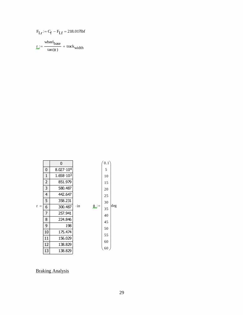
FLr Cf FLf 218.017lbf
rwheelbase
tan ( )trackwidth
r
0
0
1
2
3
4
5
6
7
8
9
10
11
12
13
48.027·10
31.658·10
851.979
580.487
442.647
358.231
300.487
257.941
224.846
198
175.474
156.029
138.829
138.829
in
0.1
5
10
15
20
25
30
35
40
45
50
55
60
60
deg

30
**All inital conditions are based off estimated assumptions
Energy of vehicle in motion into thermal energy
The brake pedal
Assume weight of driver is 180 lbs
Force exerted by driver onto foot pedal:
Bore diameter of master cylinder = bmc
Hydraulic pressure transmitted to the calipers: (Assuming 100% efficiency)
The Caliper
w 3000lbf v 5mph g 32.174ft
s2
mw
g3 10
3 lb v 7.333
ft
s
KE1
2m v
2 KE 2.507 10
3 ft·lbf
L1 1.275in L2 9.45in
Fd
0.1
10
20
30
40
50
60
70
80
90
100
lbf
bmc3
4in
Amc bmc
2
2
0.442in2
Pmc
Fbp
Amc
Pmc
0
0
1
2
3
4
5
6
7
8
9
10
1.7
167.8
335.5
503.3
671.1
838.8
1006.6
1174.4
1342.1
1509.9
1677.7
psi
Fbp Fd
L2
L1
Fbp
0
0
1
2
3
4
5
6
7
8
9
10
0.741
74.118
148.235
222.353
296.471
370.588
444.706
518.824
592.941
667.059
741.176
lbf

31
Piston diameter = dp
The Clamp
dp 1.75in Pcal Pmc
Acal dp
2
2
Acal 2.405in2
Fcal Pcal Acal Fcal
0
0
1
2
3
4
5
6
7
8
9
10
4
403.5
807.1
1210.6
1614.1
2017.6
2421.2
2824.7
3228.2
3631.8
4035.3
lbf
Fclamp 2Fcal Fclamp
0
0
1
2
3
4
5
6
7
8
9
10
8.1
807.1
1614.1
2421.2
3228.2
4035.3
4842.4
5649.4
6456.5
7263.5
8070.6
lbf
32
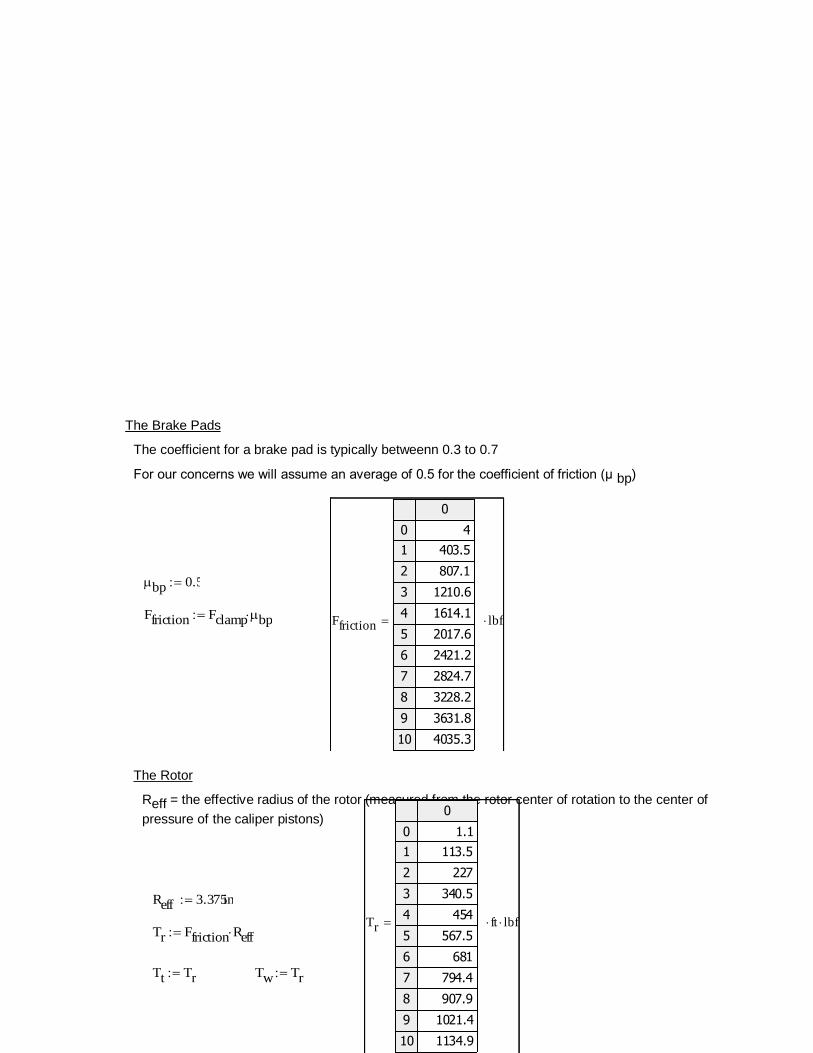
The Brake Pads
The coefficient for a brake pad is typically betweenn 0.3 to 0.7
For our concerns we will assume an average of 0.5 for the coefficient of friction (μ bp)
The Rotor
Reff = the effective radius of the rotor (measured from the rotor center of rotation to the center of
pressure of the caliper pistons)
bp 0.5
Ffriction Fclamp bp Ffriction
0
0
1
2
3
4
5
6
7
8
9
10
4
403.5
807.1
1210.6
1614.1
2017.6
2421.2
2824.7
3228.2
3631.8
4035.3
lbf
Reff 3.375in
Tr Ffriction Reff
Tt Tr Tw Tr
Tr
0
0
1
2
3
4
5
6
7
8
9
10
1.1
113.5
227
340.5
454
567.5
681
794.4
907.9
1021.4
1134.9
ft lbf

33
Since the effective rolling radius is hard to measure without real-time testing we are going to use the loaded rolling radius instead (center of wheel to contact point with horizontal surface)
Deceleration of Pedibus in motion
The Tire
(Accounts for all four tires)
Rt 12.5in
Ftire
Tt
Rt
Ftotal 4 Ftire Ftotal
0
0
1
2
3
4
5
6
7
8
9
10
4.358
435.812
871.624
31.307·10
31.743·10
32.179·10
32.615·10
33.051·10
33.486·10
33.922·10
34.358·10
lbfFtire
0
0
1
2
3
4
5
6
7
8
9
10
1.09
108.953
217.906
326.859
435.812
544.765
653.718
762.671
871.624
980.576
31.09·10
lbf
aFtotal
m
a
0
0
1
2
3
4
5
6
7
8
9
10
0.047
4.674
9.348
14.022
18.696
23.37
28.044
32.718
37.392
42.065
46.739
ft
s2

34
Stopping Distance
SDv
2
2 a
SD
0
0
1
2
3
4
5
6
7
8
9
10
575.293
5.753
2.876
1.918
1.438
1.151
0.959
0.822
0.719
0.639
0.575
ft

35

36

37