Part III Appendices - Springer978-3-540-28500-7/1.pdf · Within commercial explosives, ......
55
Part III Appendices
Transcript of Part III Appendices - Springer978-3-540-28500-7/1.pdf · Within commercial explosives, ......

Part III
Appendices

A
Physics of detonation
This appendix1 is intended to shed some light on the nature of explosions andtheir effects upon soil/rock.
A.1 Detonation
A detonation front is a shockwave which breaks the molecules of the explo-sive (which is a mixture of oxygen and combustible substances) into pieces.This takes place within a zone whose thickness is comparable to the free flightof the molecules (approx. 10−5 to 10−6 cm). Subsequently an exotherm re-action (oxidation) takes place. The result of this oxidation is a mixture ofgases. Fig. A.1 shows a snapshot of the various zones involved in a detonatingcylindrical charge.
Fig. A.1. Detonation zones within a cylindrical charge
1It is based mainly on B.N. Kutusow’s book ’Rasruscheniye gornikh porodvsrivom’ (Rock Blasting), Publishing House of the Moscow Institute of Mining,Moscow 1992.

382 A Physics of detonation
The detonation front propagates with the supersonic speed uD. In zone 0 theexplosive has not yet ’felt’ the detonation and is still in its initial state. Inzone 1 the chemical reaction takes place, but the substances involved have notas yet expanded. The expansion takes place within zone 2.The boundary between zones 1 and 2 is a moving discontinuity surface. Inthe case of a stable (or stationary, if registered by an observer moving withthe velocity uD) detonation, the discontinuity moves with the speed uD. Thecombustion in zone 1 is the driving force for this process.The energy released by the combustion propagates to the detonation front andkeeps it working. This is the mechanism of the so-called homogeneous detona-tion, which occurs within homogeneous explosives and propagates with speedsuD = 6 to 7 km/s. Within commercial explosives, where mixtures contain cer-tain inert components, the processes are more complex.The duration (speed) of the chemical reaction within zone 1 depends on theradius r0 of the charge. Note that for each type of explosive there is a charac-teristic (critical) radius rc and that the detonation expires if the charge radiusis smaller than the critical one. In the range rc < r0 < rg the detonation speeduD increases with r0, Fig. A.2.
Fig. A.2. Detonation speed uD in dependence of the size of the charge
The ratio of detonation speed uD to the chemical reaction time tc is a lengthand is characteristic for a particular explosive. It indicates the critical massof the explosive. If the mass is smaller than the critical mass, then the chargeis scattered by the previous detonation, so that the detonation cannot becontinued.2).Note that all mixtures of combustible substances and oxygen suppliers candetonate provided that the exotherm reaction releases sufficiently energy, thatthe size of the mass is sufficiently large and that there is an appropriateignition.
2According to Yu. Khariton, see Ia.B. Zeldovich and A.S. Kompaneets, Theoryof Detonation, Academic Press, 1960
A.2 Underground explosions 383
Explosive critical diameter (mm)Lead acid 0.01-0.02Hexogen 1.0-1.5Trotyl 8.0-10Ammonite 10-12
The critical mass of an explosive also depends on its containment. It is reducedif the explosive is encased in such a way that the expansion of the resultinggases is impeded. Therefore, explosive cartridges should abut to the boreholes.
A.2 Underground explosions
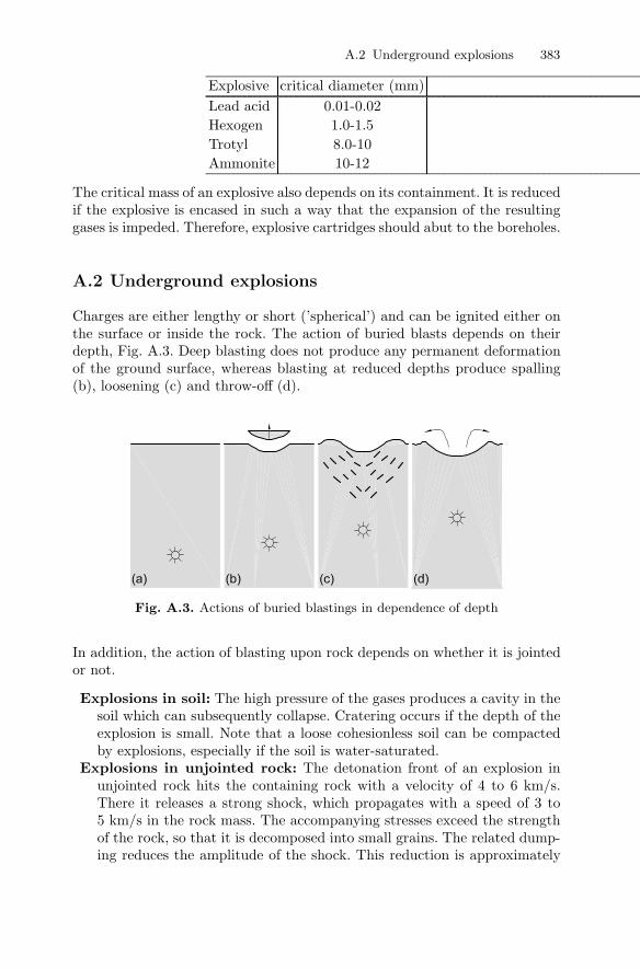
Charges are either lengthy or short (’spherical’) and can be ignited either onthe surface or inside the rock. The action of buried blasts depends on theirdepth, Fig. A.3. Deep blasting does not produce any permanent deformationof the ground surface, whereas blasting at reduced depths produce spalling(b), loosening (c) and throw-off (d).
Fig. A.3. Actions of buried blastings in dependence of depth
In addition, the action of blasting upon rock depends on whether it is jointedor not.
Explosions in soil: The high pressure of the gases produces a cavity in thesoil which can subsequently collapse. Cratering occurs if the depth of theexplosion is small. Note that a loose cohesionless soil can be compactedby explosions, especially if the soil is water-saturated.
Explosions in unjointed rock: The detonation front of an explosion inunjointed rock hits the containing rock with a velocity of 4 to 6 km/s.There it releases a strong shock, which propagates with a speed of 3 to5 km/s in the rock mass. The accompanying stresses exceed the strengthof the rock, so that it is decomposed into small grains. The related dump-ing reduces the amplitude of the shock. This reduction is approximately

384 A Physics of detonation
proportional to 1/r5, where r is the distance from the charge. In a dis-tance of r ≈ 5 to 6 r0 (r0 = radius of the charge) the propagation speedis reduced to the speed of elastic compression waves, but the associatedstresses still exceed the strength of the rock, which is destroyed up to adistance of 10 to 12 r0, mainly by radial fissures.Beyond this zone elastic waves propagate and may disturb or damagenearby structures. Besides the direct action of the propagating shocksthere are also some effects due to the pressure (4 to 7·103 MPa) of thereleased gases. The proportion of fumes penetrating into the rock fissuresapprox. amounts to 30 to 40 vol % for uncontained explosions, and to70 vol % for contained ones.If the charge is placed near the ground surface, then the compression wavesare reflected on the surface and come back as extension waves (Fig. A.4).One can imagine that the source of these reflected waves is the mirrorlocation of the charges. As the tensile strength of rock is much lower thanits compressive strength, the reflected waves are much more destructive.
Fig. A.4. Reflexion of compression waves at the ground surface
Explosions in jointed rock: Reflections at the joints are responsible forthe much stronger attenuation of the waves at increasing distance fromthe charge. Thus, the destroyed zone is much smaller in case of jointedrock.
The above statements only refer to chemical explosions. For the effects ofnuclear underground explosions see the article of Fairhurst.3
A.3 Interaction of charges
The ignition of solitary charges is not usual in mining and tunnelling. Instead,many charges are ignited and the interaction of the detonations produces some
3Ch. Fairhurst, Rock Mechanics of Underground Nuclear Explosions, ISRM NewsJournal, 6, 3/2001, 21-25

A.3 Interaction of charges 385
beneficial effects. In Fig. A.5 we see that the action of two simultaneous det-onations is enhanced along their connecting line, whereas it is attenuatedoutside this line. To understand this effect one has to note that the radialstresses are compressive ones, whereas the circumferential stresses are exten-sive. Thus, at point A we have an enhancement of stress, whereas the stressis reduced at point B. This effect is exploited to produce smooth surfaces ofblast excavation.
Fig. A.5. Stress fields due to simultaneous detonation of the charges 1 and 2
So-called millisecond blasting is applied to improve the destruction of rockand to reduce the disturbance in the neighbourhood. An ignition delay by acertain time Δt has the following effects:
1. Interference of compression waves emanating from adjacent charges (Δt <5 ms)
2. Formation of additional surfaces (15 < Δt < 200 ms)3. Additional demolition due to collision of individual blocks (Δt > 200 ms)
These effects can be roughly explained as follows (the underlying theory isstill incomplete):
Interference: The compression wave starting from charge 1 reaches theground surface at speed v (Fig. A.6) and is reflected there. As it is nowan extension wave, it reaches after the time lapse Δt =
√a2 + 4y2/v
the charge 2, which is ignited exactly at this time. Such delays can beachieved by loops in the ignition string (the detonation propagates withinthe ignition string with a speed of 6.5 m per millisecond). Delays can alsobe achieved if one uses detonators that are triggered by the compressionwave. Utilisation of interference presupposes very precise ignition times.They can hardly be calculated, especially in the case of jointed rock.
Formation of additional surfaces: Free surfaces are of importance be-cause they reflect compression waves transforming them to extensionwaves. The effect is shown in Fig. A.7.

386 A Physics of detonation
Fig. A.6. Reflexion of compression wave at free surface
Fig. A.7. The ignition of the charges A forms additional free surfaces
Collision: Rock blocks from the second ignition fly with a velocity of 20 to60 m/s and impinge the blocks from the first ignition, the velocity of whichhas reduced to approx. 3 to 6 m/s. The maximum demolition is achieved ifthe two blocks have perpendicular orbits and the relative velocity amountsat least 15 m/s.

B
Support of soil with a pressurised fluid
Consider the interface of soil with a fluid. The soil is fluid-saturated and thereis no separating membrane between soil and fluid. Applying a pressure uponthe fluid gives rise to percolation of the fluid through the soil. The hydro-dynamic drag force exerted by the fluid upon the grain skeleton is −dp/dxfor a flow in horizontal direction. This is a volume force (i.e. a force exertedupon a unit volume) that stabilises the grain skeleton. Thus, it is importantto note that the stabilisation is not due to the applied pressure p but dueto the pressure gradient dp/dx. In other words, the stabilising action is notof hydrostatic but of hydrodynamic nature. Of course, the distribution of p(and, consequently, of dp/dx) depends on the hydraulic boundary conditionsand, in general, the pressure gradient at the interface will not be particularlyhigh. This will be e.g. the case if the considered fluid is water. If, however, thefluid is a bentonite suspension then the soil pores adjacent to the interface willbe clogged very soon after the beginning of the percolation. This is the casebecause a bentonite suspension is a so-called Bingham-fluid that will no flowif the applying shear stress is lower than a limit τf .1 The bentonite penetratesinto the soil and forms a so-called filter cake of the thickness l. To estimate l,we assume that the pore is a cylinder with diameter d. Equilibrium of forcesyields
l π d τf = p π d2/4 ,
hence l = pd/(4τf). From experience we may set d ≈ 2 d10, where d10 is thegrain diameter of soil not exceeded by 10 % of the soil mass. Thus,
l ≈ d10 · p2 τf
.
Obviously, for large τf and small d10 the obtained penetration length (orcake thickness) l is very small. Thus, the filter cake can be considered as animpermeable membrane applied upon the interface.
1In other words, the bentonite suspension is a clay with a very high liquid limitwL and a very low undrained cohesion cu ≡ τf .

C
A simple analytical approximation for frostpropagation
As is known, the propagation of heat occurs with radiation and/or conduction.Here we neglect radiation. The heat flux q is proportional to the temperaturegradient: q = −λ∇T . The factor of proportionality λ is called thermal conduc-tivity. Thus, the amount of heat flowing into a volume element within a timeunit reads −divq = λdiv(∇T ) = λ� T . Herein, � is the Laplace-operator.
The influx of heat causes a rise of temperature per time unit:∂T
∂t= − 1
c�divq.
� is the density, c is the specific heat of the considered material. From theseequations follows the differential equation of Fourier
∂T
∂t=
λ
c�� T . (C.1)
α :=λ
c�is the diffusivity.
Some data follow, which are useful for thermodynamic computations:
heat conductivity λ (kJ/(m·h·◦K))Sand frozen 18.4Sand unfrozen 9.2clay frozen 9.6clay unfrozen 6.3
specific heat c (kJ/(kg·◦K))water 4.18ice 1.80
0.80soil depends strongly
on water content
Latent heat of water: 334.5 kJ/kg

390 C A simple analytical approximation for frost propagation
Let us consider a long freezing pipe with an external diameter 2r0, which issurrounded by frozen soil of radius R (Fig. C.1). We consider a plane problemwith axial symmetry, i.e. there is no temperature flux in z-direction. Due topermanent loss of heat the radius of the frozen soil increases with the rate u =R. The surface R=const is thus a moving surface of discontinuity. Referringto this discontinuity the balance equations have to be expressed as jumprelations. Let [x] denote the jump of a quantity x across the discontinuity.The jump relation for energy balance reads (for a non-moving medium)1
Fig. C.1. Propagation of frost around freezing pipes
[�eu− q] = 0 . (C.2)
e is the specific internal energy, i.e. the internal energy per volume unit. Asis known, internal energy is that part of the energy of a body which does notdepend on the motion of the observer. If we denote the frozen soil with thesubscript b and the unfrozen soil with a, Equ. C.2 reads: �aeau−qa = �bebu−qbor
u(�aea − �beb) = qa − qb = λb
(∂T
∂r
)b
− λa
(∂T
∂r
)a
(C.3)
(∂T
∂r
)a
and(∂T
∂r
)b
denote the right and the left limits at r = R, respectively.
We set � := �a ≈ �b. h := ea − eb is the latent heat, i.e. the heat that mustbe extracted from the soil to freeze it. To determine the propagation of thefreezing front with time we have to solve the following initial value problem:
For t = 0: T = T∞ in r0 < r <∞For t > 0: T = T0 for r = r0
T = T1(= 0◦C) for r = R
T = T∞ for r → ∞1See e.g. E. Becker and W. Burger: Kontinuumsmechanik (equation 5.22), Teub-
ner, 1975

C A simple analytical approximation for frost propagation 391
In the ranges r0 < r < R and r > R the differential equation C.1 is valid andfor r = R the jump relation C.3 is valid. As the boundary r = R varies withtime, we have a so-called Stefan-problem.
1T
0T
r0
R
T
r
8T
Fig. C.2. Instantaneous temperature distribution around a freezing pipe
To obtain an approximate solution of this complicated initial-boundary-valueproblem, we assume the following distributions of temperature:
T = Tb = T0 + (T1 − T0)(r − r0R− r0
)μ
for r0 < r < R (C.4)
and
T = Ta = T∞ − (T∞ − T1)( rR
)ν
for R < r <∞ , (C.5)
where the parameters μ and ν are not yet determined. To use the Laplace-Operator in cylindrical coordinates (with ∂
∂z ≡ 0)
ΔT =1r· ∂T∂r
+∂2T
∂r2,
we differentiate the expressions (C.4) and (C.5)
∂Tb
∂r= (T1 − T0)μ
(r − r0R− r0
)μ−1 1R− r0
, (C.6)
∂2Tb
∂r2= (T1 − T0)μ(μ− 2)
(r − r0R − r0
)μ−1 ( 1R− r0
)2
, (C.7)

392 C A simple analytical approximation for frost propagation
∂Ta
∂r= −ν(T∞ − T1)
( rR
)ν−1 1R
, (C.8)
∂2Ta
∂r2= −ν(ν − 1)(T∞ − T1)
( rR
)ν−2 1R2
. (C.9)
The derivatives with respect to time t are:
∂Tb
∂t= −R(T1 − T0)μ
(r − r0R− r0
)μ−1r − r0R − r0
2
, (C.10)
∂Ta
∂t= Rν(T∞ − T1)
( rR
)ν−1 r
R2. (C.11)
Using equations C.8, C.9 and C.11 we write the differential equation C.1 atr = R + 0 (i.e. to the right adjacent to the frost boundary). It then follows
ν = − R
αa·R (C.12)
with αa = ( λc�)a. Using (C.6), (C.7), (C.10) we write Equ. C.1 at r = R − 0
(i.e. to the left, adjacent to the frost boundary). It follows
μ = 1 −(R
αb+
1R
)· (R− r0) . (C.13)
We introduce the obtained expressions into the jump relation (C.2) and ob-tain:
R�h = λb(T1 − T0)1
R− r0
[1 −
(R
αb+
1R
)(R− r0)
]− λa(T∞ − T1)
R
αa.
This is differential equation for R(t). With the abbreviations
A := �h+ �ca(T∞ − T1) + �cb(T1 − T0)B := λb(T1 − T0)
it reads:
RA = B
(1
R− r0− 1R
)= B
r0(R− r0)R
.
Separation of variables leads to

C A simple analytical approximation for frost propagation 393
(R2 −Rr0)dR =B
Ar0dt
from which follows the solution (taking into account the initial condition R =r0 for t = 0)
13(R3 − r30) −
12r0(R2 − r20) =
B
Ar0t . (C.14)
By means of Equ. C.14 we can approximately determine the closure time ts,after the lapse of which the frozen soil cylinder obtains the radius a/2. Withthe abbreviation
C =r04A
(√−6Bt(r20A− 6Bt) − 1
4(r20A− 12Bt)
)
the solution of equation C.14 reads:
R = C13 +
14· r
20
C13
+r02
.
If we set R equal to a/2, where a is the distance between two adjacent freezingpipes, we obtain the closure time ts. Taking into account that r0 << R = a/2,we can simplify Equ. C.14 as follows: Dividing by r30 we obtain
13
[(R
r0
)3
− 1
]− 1
2
[(R
r0
)2
− 1
]=
B
Ar20ts .
As(
Rr0
)3
�(
Rr0
)2
� 1, we obtain with R = a2 :
ts ≈ 13· A
Br0·(a
2
)3
.
Herein, ts is the closure time i.e. the time needed for two adjacent freezingfronts to get in touch (Fig. C.1). The heat Q extracted from the freezing pipeper time and length units reads:
Q = 2πr0q|r0 ≈ 2πr0λbT1 − T0
R− r0.

D
Rigorous solution for the steady water inflowto a circular tunnel
The rigorous solution, obtained with complex analysis, is presented here infull length, as it can be hardly found in the literature. We consider a tunnelwith circular cross section within a soil/rock with homogeneous and isotropicpermeability. With an appropriate drainage system, the circumference of thetunnel is kept at a constant hydraulic head ha.The water ingress into the tunnel can be determined by conformal mapping.The circle and the horizontal line in Fig. D.1 can be transformed to twoconcentric circles by the Mobius transformation
w = f(z) =r(z − cr)cz + r
with c = ih−√
h2 − r2
r= ib and i =
√−1.
Fig. D.1. Circle and line in the complex plane
f(z) maps the circle zz = r2 into the same circle: With f(z) = r(z+ cr)−cz+ r we
obtain f f = r2. As usual in complex analysis, the bar denotes the conjugatecomplex number.

396 D Rigorous solution for the steady water inflow to a circular tunnel
The horizontal line z = ih+ a , a ∈ R, is mapped to a circle with radius R:
f(z) =r (ih+ a− cr)c (ih+ a) + r
= r2a+ i
√h2 − r2
(h−√h2 − r2)(ai+
√h2 − r2)
� |f f | =r2
h−√h2 − r2
=: R .
We introduce the complex potential F (z) = log f(z) = log r + log(z − cr) −log(cz+ r). With logw = log |w|︸ ︷︷ ︸
Φ
+iΨ we obtain Φ as the potential to describe
flow into the tunnel. At the circumference of the tunnel it obtains the value
ΦT = log r
and at the straight line Im(z) = h it obtains the value
ΦS = logR.
In order to attain there the prescribed values ha andH (Fig. 8.7), respectively,it has to be re-scaled:1
Φ∗ :=R − ρ
R− r
Φ
ΦTha +
ρ− r
R− r
Φ
ΦSH = ΦQ
with
Q =1
R− r
[ha
log r(R− ρ) +
H
logR(ρ− r)
].
Noting, however, that Q = Q(ρ) we infer that this re-scaling is not admissible,since Φ∗ is no more a potential (ΔΦ∗ �= 0, Δ is the Laplacian operator). Thus,we have to proceed as follows: By appropriate choice of the datum of geodetichead we may set H = 0. In this case, ha obtains the meaning of Δh, i.e. thehead difference between the line Im(z) = h and the tunnel circumference,Δh := H − ha. The re-scaled potential now reads Φ� = Δh · Φ−ΦS
ΦT−ΦS.
With z = ρ eiϕ = ρ (cosϕ + i sinϕ) and ∂∂ρ log |f | = ∂
∂ρ log(f f)1/2 =12
∂∂ρ log f f we obtain:
∂Φ
∂ρ=
∂
∂ρ
[log |ρ eiϕ − cr| − log |cρ eiϕ + r|
]=
∂
∂ρ
[log |ρ cosϕ+ i(ρ sinϕ− br)|
− log | − bρ sinϕ+ r + ibρ cosϕ|]
=ρ− rb sinϕ
ρ2 − 2ρrb sinϕ+ b2r2− b2ρ− br sinϕb2ρ2 − brρ sinϕ+ r2
∂Φ
∂ρ
∣∣∣∣ρ=r
=1r
1 − b2
1 − 2b sinϕ+ b2
1In this section ρ denotes the radial coordinate

D Rigorous solution for the steady water inflow to a circular tunnel 397
Thus, the radial velocity at the tunnel circumference reads
v = −K∂Φ�
∂ρ= −K Δh
ΦT − ΦS
∂Φ
∂ρ
∣∣∣∣ρ=r
=KΔh
log(R/r) · r · 1 − b2
1 − 2b sinϕ+ b2
To integrate along the circumference we use the expression
∫dϕ
A−B sinϕ= −
tan−1
[B cos ϕ/2−A sin ϕ/2
cos ϕ/2·√A2−B2
]√A2 −B2
with A := 1 + b2 , B := 2b ,√A2 − B2 = 1− b2 . Thus the water ingress
q =∫ 2π
0
vrdϕ = −KΔh(1 − b2)log(R/r)
∫ 2π
0
dϕ
1 + b2 − 2b sinϕ
reads:
q =2KΔh
log(R/r)tan−1 2b cosϕ/2 − (1 + b2) sinϕ/2
cosϕ/2 · (1 − b2)
∣∣∣∣∣π/2
−π/2
=2KΔh
log(R/r)
(π
2− −π
2
)
Using tan−1 x+ tan−1 y = tan−1 x+y1−xy we finally obtain
q =2πKΔhlog(R/r)
=2πK(H − ha)
log(
r
h−√h2 − r2
) . (D.1)
Equ. (D.1) shows that q depends non-linearly on the tunnel radius. E.g. forh = 30 m, an increase of r from 3 m to 6 m (i.e. by 100%) causes an increaseof q of only 30%.The merit of equation D.1 lies in its consistency and validity not only fordeep but also for shallow tunnels. It presupposes homogeneous and isotropicpermeability.

E
Aerodynamic pressure rise in tunnels
We consider the case of a piston (train) entering with velocity V into a tube(tunnel). For simplicity, we neglect the gap between piston and tube. As shownin Fig. E.1, a shock front is released and moves with the propagation speedc. In region 1 the velocity v, pressure p and density of air are V , p1, ρ1,respectively, whereas the corresponding values in region 0 are: 0, p0, ρ0.
Fig. E.1. Piston moving within a tube
Mass balance across the shock requires
[ρ(c− v)] := ρ1(c− v1) − ρ0(c− v0) = 0 ,
hencec =
ρ1
ρ1 − ρ0V . (E.1)
Momentum balance across the shock requires:
[ρv(c− v) − p] := ρ1v1(c− v1) − p1 − ρ0v0(c− v0) + p0 = 0 , (E.2)
henceρ1V (c− V ) = p1 − p0 . (E.3)
Adiabatic compression of a gas is described by p/ρκ = const � dp = pρκdρ
with κ being the adiabatic exponent (κ ≈ 1.4 for air). Thus,

400 E Aerodynamic pressure rise in tunnels
p1 − p0 ≈ p0
ρ0κ · (ρ1 − ρ0) . (E.4)
Combining equations E.1, E.3 and E.4 yields a quadratic equation for c, thesolution of which reads
c =12
(V +
√V 2 + 4
p0
ρ0κ
). (E.5)
With the known values for atmospheric pressure and density, i.e. with ρ0
= 1,293 g/cm3 and p0 = 105 Pa = 105 N/m2, we obtain 4 p0ρ0κ = (659
km/h) 2. Thus, for a train with V = 200 km/h we obtain c = 444 km/hand Δp = p1 − p0 = p0 · κ
c/V −1 = 105 Pa· 1.4444/200−1 = 114 kPa.
This value is far too high, because the air flow in the gap has been neglected.If we take the gap into account, we have to consider the ratio of the crosssection areas n := Atunnel/Atrain. Neglecting air compressibility and assum-ing that the velocities are averaged over the corresponding cross sections,continuity yields (Fig. E.2) vAtunnel = V Atrain − vg(Atunnel −Atrain) or
v = nV − (1 − n)vg . (E.6)
In the equations E.1, E.3 and E.5 V has now to be replaced by v. The gapvelocity vg is related to the pressure rise Δp via Equ. 2.2 and decreases withincreasing length l . Thus, it depends on the travel time of the train in thetunnel.
Fig. E.2. Piston with gap
For any time t, v must be determined iteratively from
Δp = λl
d
g
2v2
g = p0κ
c/v − 1.
Herein, d is an appropriate hydraulic radius for the flow in the gap.

F
Multiphase model of reinforced ground
For multiphase media (such as composite materials) it is assumed that eachpoint is occupied by all constituents, which in our case are ground and re-inforcement. The corresponding field quantities are denoted by the indices gand r, respectively. Let us consider a representative volume element (REV)with the volume V . The included volumes of ground and reinforcement areVg and Vr, respectively. The corresponding volume fractions are αg := Vg/Vand αr = Vr/V with αg + αr = 1. It can be shown that the volume frac-tions are equal to the area fractions, e.g. αg = Ag/A with Ag being the crosssection occupied by ground, and A being the total cross section. Referringto multiphase media and quantities (such as density and stress) of the sev-eral constituents, it has to be distinguished between the ’real’ (or ’effective’)quantities, that prevail (or are averaged) over the individual phases and the’partial’ quantities, that are averaged over the entire REV. Thus, we have thereal densities of ground and reinforcement, ρg and ρr, respectively. The corre-sponding partial densities are ρg = αgρ
g and ρr = αrρr. Similarly, it has to be
distinguished between the stresses σg and σr on the one hand, and σg = αgσg
and σr = αrσr on the other.1 In the quasi-static case (i.e. accelerations are
negligible) the equations of equilibrium for the two phases read:
∇ · σg + Prg + ρgg = 0 (F.1)∇ · σr + Pgr + ρrg = 0
g is the gravity acceleration, Prg = −Pgr is a vector that characterises theinteraction of the two phases. Prg is the force per unit volume exerted bythe reinforcement upon the ground. For the case of the fully mobilised rigid-idealplastic shear stress τ0 the interaction force can be determined as follows:The shadowed volume (Fig. F.1)
1In the notation of multiphase media, σg is the ’effective’ stress in the ground.This quantity should not be confused with the effective stress in the usual sense ofsoil mechanics.

402 F Multiphase model of reinforced ground
V0 =∫ θ0
0
∫ b
0
∫ r0+l
r0
rdrdzdθ ,
with θ0 = a/r0, corresponds to one bolt. Thus, the interaction force πdτ0l isobtained as:
πdlτ0 =∫ θ0
0
∫ b
0
∫ r0+l
r0
Prgrdrdzdθ . (F.2)
Fig. F.1. Volume corresponding to one bolt
Fig. F.2. Ground reaction line altered by the action of bolts and correspondingsupport line.
Knowing that Prg depends on r, we set Prg = const/r and obtain from (F.2):
Prg =πdτ0r0ab
· 1r
.

F Multiphase model of reinforced ground 403
Obviously, for very thin bolts (d → 0) the interaction force Prg becomesnegligible and, thus, its neglection in Sect. 15.1.3 becomes justified. A non-vanishing interaction force can be taken into account as follows: As usualfor deep tunnels, we neglect gravity (g ≈ 0). Then, equation F.1 written incylindrical coordinates reads:
dσr
dr+σr − σθ
r= −πdτ0r0
ab· 1r
(F.3)
Introducing the Mohr-Coulomb yield condition leads to
dσr
dr− (σθ + σr)sinϕ
r− 2ccotϕ
r= −πdτ0r0
ab· 1r
. (F.4)
We can reduce Equ. F.4 to the original equation if we replace the cohesion cby c, where
c := c− τ0πdr02ab
· tanϕ. (F.5)
Thus, the action of the bolts upon the ground is equivalent to a reductionof cohesion according to Equ. F.5. Note that Equ. F.5 holds for ϕ > 0. Forϕ = 0 and σθ − σr = 2c the equilibrium equation F.4 has to be replaced by
dσr
dr− 2c
r= −πdτ0r0
ab· 1r
.
The solution (14.31) will be valid if we replace c by c, where
c := c− τ0πdr02ab
.
The volume force due to the action of the bolts alters the ground reaction lineas shown in (Fig. F.2).

G
Deformation of a tunnel due to seismic waves
We omit here the indices s and p; the operations stated below should beexecuted twice, once for the p-wave and once for the s-wave.From the displacement field u(x, t) we obtain the (geometrically linearised)deformation field:
ε =12
[∂u∂x
+(∂u∂x
)T]
In index notation we obtain:
ui = a li exp
[iω
(t− lkxk
c
)]
�∂ui
∂xj= −i ω
ca li lj exp
[iω
(t− lkxk
c
)]= −i ω
cljui
hence
εij = −i ω2c
(liuj + ljui) = −i ωca lilj exp
[iω
(t− lkxk
c
)].
The strain ε of the tunnel axis is given as:
ε = ε : t ⊗ t = εij ti tj ,
εmax =ω
ca li lj ti tj .
Let α denote the angle between the tunnel axis t and the wave propagationdirection l. With liti = cosα we finally have
εmax =ω
ca cos2 α

406 G Deformation of a tunnel due to seismic waves
Now let us determine the change of the curvature κ of the tunnel axis imposedby the displacement field u(x, t). We assume that the initial curvature is smalland, thus, negligible. Let the vectorial representation of the tunnel axis ber(s) = r0(s) + u(s), where s is the arc length. The curvature is then given byκ ≈ |r′′| , where the prime denotes derivation with respect to s. We thus have
Δκ = κ− κ0 ≈ κ ≈ |u′′| .
u′′ can be determined as follows:
u′ = u′i =∂ui
∂xj
∂xj
∂s=∂ui
∂xjtj .
Similarly
(u′i)′ =
∂
∂xk
(∂ui
∂xjtj
)tk
=∂2ui
∂xk∂xjtj tk +
∂ui
∂xj
∂tj∂xk
tk =∂2ui
∂xk∂xjtj tk +
∂ui
∂xj
∂tj∂s
For an initially straight tunnel (∂ti/∂s = 0) we have:
u′′i =∂2ui
∂xk∂xjtk tj
hence
κ =
∣∣∣∣∣ ∂2ui
∂xk∂xjtk tj
∣∣∣∣∣� κ =
ω2
c2lj lk tj tk |ui|
and
κmax =(ωc
)2
a lj lk tj tk
or
κmax =(ωc
cosα)2
a .

H
A rational approach to swelling
In mechanical terms, swelling can be described as follows: We decomposethe strain ε into a part due to swelling (εs) and a part due to mechanicalloading/unloading (εb):
ε = εs + εb . (H.1)
To allow for immediate access of water to the swelling minerals, we consideran infinitely thin layer. By lack of experimental results, we assume the mostsimple relation, namely a linear one, between εs and w:
εs = εs,maxw
wmax. (H.2)
Of course, this relation can be replaced by a more realistic one as soon ascorresponding test results are available. w is the water content. It refers notonly to the free water within the pores (as usual in soil mechanics) but alsoto the water responsible for swelling.wmax is the water content at saturation, i.e. when no more swelling occurs.The propagation of the water within the ground is a diffusion process governedby the known diffusion equation, also known from the consolidation theory:
∂w
∂t= c
∂2w
∂z2(H.3)
for problems with one spatial dimension. For simplicity, we have assumed thatc is constant. Obviously, the same solution as for 1D-consolidation applies. Forthe mechanical part of the strain we use the known logarithmic relation of soilmechanics:
εb = −Cb lnσ
σ0, (H.4)
where compression is taken as negative. σ0 is the initial stress. Again, insteadof equation H.4 a more appropriate relation can be used if available.

408 H A rational approach to swelling
We consider now a layer with thickness l. The access of water to its lowerand upper boundaries is given at t = 0. The instantaneous distribution ofwater content within this layer is given by the same isochrones known fromthe consolidation theory (Fig. H.1).
Fig. H.1. Distribution of w across the thickness 0 ≤ z ≤ l of a swelling layer atseveral times
If w is known for every depth z and for every time t, the upheaval due toswelling can be obtained:
(�l)s =
l∫0
εs dz = εs,max
l∫0
w
wmaxdz = εs,max
l∫0
μdz = εs,maxμ l (H.5)
The solution of the diffusion equation H.3 yields μ as function of the dimen-sionless time τ := 4ct/l2. In the theory of consolidation, μ is the ratio ofthe actual settlement at time t to the final settlement s∞. Here, μ denotesthe ratio of the (not inhibited) expansion due to swelling at time t to thefinal expansion for t → ∞. As known, the relation between μ and τ can beapproximated by
τ ={
π4μ
2 for μ < 0, 6−0, 933 log10(1 − μ) − 0, 085 for μ > 0, 6
From equation H.5 follows the average expansion due to swelling
εs :=(�ll
)s
= μ εs,max . (H.6)
From (H.1), (H.4) and (H.6) follows the total expansion of the consideredlayer:
ε = −Cb lnσ
σ0+ εs,max μ
In a semilogarithmic diagram (Fig. H.2) this relation between ε and σ isrepresented by straight lines.

H A rational approach to swelling 409
Fig. H.2. Relation between ε and σ. The access of water to the boundaries occursat t = 0 for ε = 0 and σ = σ0. The case μ = 1 is obtained for t→ ∞.
The family of straight lines in Fig. H.2 is parametrised by μ (resp. the timet). Adding a compressible layer, consisting e.g. of soft grains, prescribes to theswelling layer a particular σ-ε-relation, e.g. an elastic - idealplastic relation.If we plot this relation into Fig. H.2 we obtain the development of stress andstrain with time (Fig. H.3).
Fig. H.3. If the relation between ε and σ is prescribed, as shown here by the elastic-idealplastic curve, then the development of strain with time can be inferred fromthe shown parametrisation.

9
Glossary

412 9 Glossary
9.1 English - German
abutment Auflageradit Fensterstollenadmission Zulassungadvance grouting Vorausinjektionadvance investigation Vorerkundungaggressiveness Aggressivitatanchor length Ankerlangeangle of dilatancy Dilatanzwinkelapproximation Naherungapproximative solution Naherungsformelarc-length Bogenlangearticulation Gelenkaxial symmetry Zylindersymmetrieback-up Nachlauferbar spacer Abstandhalterbasin Muldebeam Tragerbearing construction Tragsystembearing Lagerbear tragenbench Strossebentonite Bentonitbifurcation Verzweigungbitumen Bitumenblow-out Ausblaserbody force Massenkraftboom Lafetteborehole Bohrlochboulder Findlingbound theorem Schrankentheoremboundary condition Randbedingungboundary value problem Randwertproblemboundary Grenze, Randbound Schrankebreak through Durchbruchbreakdown bay Pannenbuchtbreakthrough point Durchstoßpunktbrittle sprodebuckle beulenbuilding splice Bauwerksfugebulkhead Abschottungbuoyancy Auftriebcable duct Kabelkanalcake Filterkuchencantilever Auskragungcarriageway Fahrbahncased verrohrt

9.1 English - German 413
casing Verrohrungcast concrete Ortbetoncatchpit Auffangbeckencave-in Verbruch, Niederbruchcavity wall Lochrandcement grouted rock dowel SN-Ankercement mortar Zementmortelchainage Stationchemical composition Chemismuschisel Meisselcircular cross section Kreisquerschnittcircumference Umfangclay Tonclearance lichte Breitecoefficient Beiwert, Koeffizientcohesion Kohasioncohesive bindigcollapse load Bruchlastcollapse mechanism Bruchmechanismuscollapse Versagenconductivity Leitfahigkeitconsistency Konsistenzconsolidation Konsolidierungconstruction design Ausfuhrungsplanungconstruction level Bauzustandconstruction lot Baulosconstruction site Baustelleconstruction Baumaßnahmecontaminated material Altlastcontinuum mechanics Kontinuumsmechanikcontractancy Kontraktanzcontractor Auftragnehmerconvergence Konvergenzcore drilling Kernbohrungcore Bohrkern, Kerncrossover Querschlagcrown displacement Firstsenkungcrown settlement Firstsetzungcrown Firste, Kalottecrusher Steinbrechercurvature radius Krummungsradiusdamping Dampfungdaylight collapse Tagbruchdeformability Verformbarkeitdeformable verformbardesign load Lastannahmedesign-build contract funktionale Ausschreibungdesign planendiaphragm wall Schlitzwand

414 9 Glossary
diffusivity Temperaturleitzahldigging bucket Baggerschaufeldilatancy Dilatanzdiscontinuous diskontinuierlichdisk cutter Diskenrolledisplacement Verschiebungdistortion Verzerrungdiving plate Tauchwanddrained draniertdrawback Ruckschlagdray bit Schrammeisseldrive auffahrenductile duktilelastic elastischemergency lay-by Anhaltenischeend configuration Endkonfigurationentry cut Voreinschnittenvelope Umhullendeequation of equilibrium Gleichgewichtsbedingungevaluation Auswertungexcavation face Ortsbrustexcavation radius Ausbruchradiusexcavation Auffahrung, Ausbruch, Ausheben, Vortriebexcavator Baggerexhaust Abluftexpansion joint Dehnungsfugeexploration gallery Probestollenextension test Extensionsversuchface support Bruststutzungfading Ausklingenfailure Ausfall, Bruchfar field Fernfeldfault Verwerfungfavorable gunstigfill auffullenfissure Rissflat jack Druckkissenflow Stromungforce Kraftforeman Polierfriction angle Reibungswinkelfrictional material Reibungsmaterialfrom technical point of view technischfull face advance Vollausbruchfunctional iteration Fixpunktiterationgallery Stollengang Drittelgeostatic geostatischgeotechnical engineering Geotechnik

9.1 English - German 415
grain skeleton Korngerustgranulate Schuttgutground reaction line Gebirgskennlinieground surface Gelandeoberflachegroundwater Bergwasserground Gebirgegroutability Injizierbarkeitgrouted ground Injektionskorpergrouting Injektionhalfspace Halbraumhard hut Schutzhelmheading Frontbereich, Vortriebhemisphere Halbkugelhydraulic piston Hydraulikzylinderhydrocyclone Zyklonhydrogeological hydrogeologischimmersed tunnel eingeschwommener Tunnelimpermeability Dichtigkeitinclination angle Neigungswinkelinclined geneigtincrement of displacement Verschiebungsinkrementinertia force Tragheitskraftinflection point Wendepunktinitial settlement Sofortsetzunginlet Einlageinstallation Einrichtunginteraction Wechselwirkunginterlocked length Haftlangeinvert Sohleinvestigation Erfassen, Untersuchungirreversible irreversibeliteration scheme Iterationsschemajointed gekluftetjoint Kluftkinematic kinematischlateral stress Seitendrucklattice girder Gittertragerleaking Austrittlevelling bar Abziehbohlelighting Beleuchtunglimit condition Grenzbedingunglimit state Grenzzustandline Kennlinielining Auskleidung, Schaleloading process Belastungsprozeßload Beanspruchung, Lastlocked kraftschlussiglock Schleuselong distance train Fernzug

416 9 Glossary
longitudinal section Langsschnittloose weitmaschiglowering of groundwater table Grundwasserabsenkungmarl Mergelmass force Massenkraftmaterial constant Stoffkonstantematrix Matrixmeasurement Messungmethod of excavation Ausbruchsart, Vortriebsverfahrenmethod of subgrade reaction Bettungszahlverfahrenmining worker Bergmannmobilized mobilisiertmomentum balance Impulserhaltungssatzmouth profile Maulprofilmuck spoil Bohrgut, Abraummaterialmucking Schutternnail Nagel
NATM NOTneglection Vernachlassigungnodal force Knotenkraftnodal load Knotenlastnodal point Knotenpunktnon-cohesive kohasionslosnormal consolidated normalkonsolidiertnumerical numerischobservation method Beobachtungsmethodeone-dimensional eindimensional
overburden, cover Uberdeckung, Uberlagerungshoheoverconsolidated uberkonsolidiertoverexcavation Mehrausbruchowner Bauherrpartial face advance Teilausbruchpattern of failure Bruchmusterpattern bolting Systemankerungpenetrate durchorternpermeability Durchlassigkeitperpetuation of evidence Beweissicherungpile Pfahlpilot bore Pilotstollenpin Meßbolzenpipe arch Rohrschirmpipe screen cover Rohrschirmdeckepipe spile Rohrspießplane Ebeneplasticity Plastizitatplastic plastischplastification Plastifizierungplastified plastifiziertplate load test Lastplattenversuch

9.1 English - German 417
plot Verlaufpolar coordinate Polarkoordinatepore pressure Porenwasserdruckpower law Potenzgesetzpower of dissipation Dissipationsleistungpower station Kraftwerkprecise genaupreliminary design Vordimensionierungpreloaded vorbelastetpressure bulkhead Druckwandpressure distribution Druckverteilungpressure relief Druckentlastungpressuremeter Pressiometerprimary stress Primarspannungprincipal stress Hauptspannungproof of operability Lagesicherheitsnachweisproof Nachweispropagation velocity Ausbreitungsgeschwindigkeitpump-in-test Abpressversuchquadratic quadratischquantity Großequasi-static quasistatischradial stress Radialspannungradiation damping Abstrahldampfungrail Bahnraise-boring Aufbruchbohrungadvance step Abschlagslange, -tiefereaming Aufweitungrecycling Wiederverwendungreinforcement Bewehrungrelative displacement Relativverschiebungremovable wing absetzbarer Ladetischresultant resultierendretaining wall Stutzwandrigid block Starrkorperrigid carriageway feste Fahrbahnring closure Sohlschlußroad construction Straßenbauroad traffic Straßenverkehrroadheader Teilschnittmaschinerock class Gebirgsklasserock mass Felsverbandrock measurement techniques Felsmeßtechnikrock pressure Gebirgsdruckrock rating Gebirgsklassifikationrockburst Bergschlagrock Fels, Festgesteinrod anchor Stabankerrod extensometer Stangenextensometer

418 9 Glossary
rotating cutter Schneidradrotation Drehungroughly ungefahrrule Vorschriftsafety Sicherheitsafe sichersaturated gesattigtscalar product Skalarproduktscale effect Maßstabseffektscaling Felsabraumungscatter Streubreite, streuen, Streuungscratching class Schrammklassescree Hangschuttscrew conveyor Forderschneckegasket Dichtungsealing Abdichtung, Versiegelungsegment Tubbingsemicross ventilation Halbquerluftungsettlement trough Setzungsmuldesettlement Setzungshaft Schachtshallow seichtshear band Scherfugeshear strength Scherfestigkeitshear Schubshield Schildshoulder Kampfershutter Schalwagenside gallery Ulmenstollenside Ulmesilo Siloslickenside Harnischflachesliding wedge Gleitkeilslope Steigung, Boschungslurry shield Thixschildsoftening Entfestigungsoften entfestigensoil layer Bodenschichtsoil-structure Boden-Bauwerksoil Lockergesteinsolubility Losbarkeitsolution Losungspalling Abplatzungspatial direction Raumrichtungspecial case Sonderfallspherical symmetry Kugessymmetriespherical kugelformigspoil Ausbruchsmaterialsprayed concrete Spritzbeton

9.1 English - German 419
spring Federsqueezing druckhaftstand-up time Standzeitstandpipe piezometer Grundwasserpegelstandpipe Standrohrstate variable Zustandsvariablesteel rib Ausbaubogenstep Schrittstiffness Steifigkeitstrain Dehnungstrength Festigkeitstress deviator Spannungsdeviatorstress distribution Spannungsverteilungstress field Spannungsfeldstress path Spannungspfadstress state Spannungszustandstress-free spannungsfreistress Spannungstroke Hubsubgrade reaction approach Bettungsansatzsubgrade reaction modulus Bettungsmodulsubgrade reaction Bettungsubstep Teilschrittsuperficial velocity Filtergeschwindigkeitsupport core Brustkeilsupport measure Sicherungsmittelsupport pressure Ausbauwiderstandsupporting force Stutzkraftsupport Ausbau, Sicherungsurface settlement Oberflachensetzung
survey meßtechnische Uberwachungswell schwellentail gap Ringspalttender Ausschreibungtension Zugthermal conductivity Warmeleitzahlthreedimensional dreidimensionalthrust Vorschubkrafttop heading Kalottenvortriebtorque Drehmomenttraffic lane Fahrstreifentransducer Aufnehmertransformation Umformung
transition condition Ubergangsbedingungtrapdoor Fallturtrimming Nachprofilierungtube Rohretunnel axis Tunnelachsetunneler Tunnelbauer

420 9 Glossary
tunnelling, Tunnelvortrieb, Tunnelbauturning point Umkehrnischetwist Verdrehungtwodimensional zweidimensionaluncertainty of measurement Meßunsicherheituncoupled entkoppeltundercutting Hinterschneidetechnikundercut Unterfahrungunderground unter Tageunderpining Unterfangungundrained undraniertunit vector Einheitsvektorunjointed ungekluftetunpreloaded unvorbelastetunsaturated ungesattigtunstable nachbruchigvault Gewolbevector Vektorvehicular tunnel Straßentunnelvertical stress Vertikalspannungviscosity Viskositatvolume force Volumenkraftvolume loss Volumenverlustwalkway Gehwegwall friction Wandreibungwater inrush Wassereinbruchwaterproofing Abdichtung, Versiegelungwatertight concrete WU-Betonweak zone Storzoneweak gebrachweathered verwittertweathering Verwitterungweightless gewichtsloswheel loader Radladerwire mesh Baustahlgitterwooden grid Holzrostwooden plank HolzbohleYoung´s modulus Elastizitatsmodul

9.2 German - English
Abbaukammer working chamberabsetzbarer Ladetisch removable wingAbdichtung sealing, waterproofingAbluft exhaustAbplatzung spallingAbraummaterial muck, spoilAbpressversuch pump-in-testAbschlagslange, -tiefe rate of advance, advance stepAbschottung bulkheadAbstandhalter bar spacerAbstrahldampfung radiation dampingAbziehbohle levelling barAchse axe, axisAggressivitat aggressivenessAltlast contaminated materialAnhaltenische emergency lay-byAnkerlange anchor lengthAufbruchbohrung raise-boringauffahren to driveAuffangbecken catchpitAuflager abutmentAuftrieb buoyancyAuftragnehmer contractorauffullen fillAuffahrung excavationAufnehmer transducerAufweitung reamingAusbau supportAusbaubogen steel ribAusbauwiderstand support pressureAusblaser blowoutAusbreitungsgeschwindigkeit propagation velocityAusbruch excavationAusbruchradius excavation radiusAusbruchsart method of excavationAusbruchsmaterial spoilAusfuhrungsplanung construction designAusfall failureAusheben excavationAuskleidung liningAusklingen fadingAuskragung cantileverAusschreibung tenderAuswertung evaluationBagger excavatorBaggerschaufel digging bucketBahn rail

422 9 Glossary
Bauherr ownerBaulos construction lotBaumaßnahme constructionBaustahlgitter wire meshBaustelle construction siteBauwerksfuge building spliceBauzustand construction levelBeanspruchung loadBeiwert coefficientBelastungsprozeß loading processBeleuchtung lightingBentonit bentoniteBeobachtungsmethode observation methodBergmann mining workerBergschlag rockburstBergwasser groundwaterBettung subgrade reactionBettungsansatz subgrade reaction approachBettungsmodul subgrade reaction modulusBettungszahlverfahren method of subgrade reactionbeulen buckleBewehrung reinforcementBeweissicherung perpetuation of evidencebindig cohesiveBitumen bitumenBoden-Bauwerk soil-structureBodenschicht soil layerBogenlange arc-lengthBohrgut muck spoilBohrkern coreBohrloch boreholeBruch failure, collapseBruchlast collapse loadBruchmechanismus collapse mechanismBruchmuster pattern of failureBrustkeil support coreBruststutzung face supportChemismus chemical compositionDampfung dampingDehnung strainDehnungsfuge expansion jointDichtigkeit impermeabilityDichtung seal, gasketDilatanz dilatancyDilatanzwinkel angle of dilatancyDiskenrolle disk cutterdiskontinuierlich discontinuousDissipationsleistung power of dissipationdraniert drained

9.2 German - English 423
Drehmoment torqueDrehung rotationdreidimensional threedimensionalDrittel gangDruckentlastung pressure reliefdruckhaft squeezingDruckkissen flat jackDruckverteilung pressure distributionDruckwand pressure bulkheadduktil ductiledurchortern penetrateDurchbruch break throughDurchlassigkeit permeabilityDurchstoßpunkt breakthrough pointeben planeEbene planeeinachsial, einaxial uniaxialeindeutig uniqueeindimensional one-dimensionaleinfachheitshalber for sake of simplicityeingeschwommener Tunnel immersed tunnelEinheitsvektor unit vectorEinlage inletEinrichtung installationEinwirkung actionelastisch elasticElastizitatsmodul Young´s modulusEndkonfiguration end configurationentfestigen softenEntfestigung softeningentkoppelt uncoupledentrusten outrageerfahrungsmaßig by experienceErfassen investigationexplizit expliciteExtensionsversuch extension testFahrbahn carriagewayFahrstreifen traffic lanefallen decreaseFalltur trapdoorFeder springFelsabraumung scalingFelsdecke cavity roofFelsmeßtechnik rock measurement techniquesFelsverband rock massFensterstollen aditFernfeld far fieldFernzug long distance trainfeste Fahrbahn rigid carriageway

424 9 Glossary
Festgestein rockFestigkeit strengthFestigkeitsgrenze strength limitFiltergeschwindigkeit superficial velocityFilterkuchen cakeFindling boulderFirste crownFirstsenkung crown displacementFirstsetzung crown settlementFixpunktiteration functional iterationflachengleich of equal areaFrontbereich headingForderschnecke screw conveyorfunktionale Ausschreibung design-build contractgunstig favorableGasaustritt leakingGebirge groundGebirgsdruck rock pressureGebirgskennlinie ground reaction lineGebirgsklasse rock classGebirgsklassifikation rock ratingGebirgsklassifizierung rock ratinggebrach weakGehweg walkwaygekluftet jointedGelandeoberflache ground surfaceGelandeoberkante ground surfaceGelenk articulationgenau precisegeneigt inclinedgeostatisch geostaticGeotechnik geotechnical engineeringgeotechnisch geotechnicalgesattigt saturatedgewichtslos weightlessGewolbe vaultGitternetz lattice girderGleichgewichtsbedingung equation of equilibriumGleichgewichtsgleichung equation of equilibriumGleitkeil sliding wedgeGlg. equ.Große quantityGrenzbedingung limit conditionGrenze boundaryGrenzzustand limit stateGrundwasserabsenkung lowering of groundwater tableGrundwasserpegel standpipe piezometerHochstgeschwindigkeit maximum velocityHaftlange interlocked length

9.2 German - English 425
Halbkugel hemisphereHalbquerluftung semicross ventilationHalbraum halfspaceHangschutt screeHarnischflache slickensideHauptspannung principal stressHereinbrechen cave-inHerstellung constructionHinterschneidetechnik undercutting, back-cuttingHolzbohle wooden plankHolzrost wooden gridHub strokeHydraulikzylinder hydraulic pistonhydrogeologisch hydrogeologicalImpulserhaltungssatz momentum balanceInjektion groutingInjektionskorper grouted groundInjizierbarkeit groutabilityirreversibel irreversibelIterationsschema iteration schemeKabelkanal cable ductKalotte crownKalottenvortrieb top headingKampfer shoulderKennlinie lineKern coreKernbohrung core drillingkinematisch kinematickluftig jointedKluft jointKluftabstand rock spacingKnotenkraft nodal forceKnotenlast nodal loadKnotenpunkt nodal pointKoeffizient coefficientKohasion cohesionkohasionslos non-cohesiveKonsistenz consistencyKonsolidierung consolidationKontinuumsmechanik continuum mechanicsKontraktanz contractancyKonvergenz convergenceKorngerust grain skeletonKrummungsradius curvature radiusKraft forcekraftschlussig lockedKraftwerk power stationKreisquerschnitt circular cross sectionkugelformig spherical

426 9 Glossary
Kugessymmetrie spherical symmetryLafette boomLangenanderung extensionLangenschnitt longitudinal sectionLangsschnitt longitudinal sectionLosbarkeit solubilityLosung solutionLager bearingLagesicherheitsnachweis proof of operabilityLastannahme design loadLastplattenversuch plate load testLeitfahigkeit conductivitylichte Breite clearanceLochrand cavity wallLockergestein soilMaßstabseffekt scale effectMassenkraft body forceMassenkraft mass forceMatrix matrixMaulprofil mouth profileMeßbolzen pin
meßtechnische Uberwachung surveyMeßunsicherheit uncertainty of measurementMehrausbruch overexcavationMeissel chiselMergel marlMessung measurementmobilisiert mobilizedMulde basin, recess
NOT NATMNachprofilierung trimmingNaherung approximationNaherungsformel approximative solutionnachbruchig unstableNachbrechen cave inNachlaufer back-upNachweis proof, assessmentNagel nailNeigungswinkel inclination angleNeubau constructionniederbringen undertakeNiederbruch cave innormalkonsolidiert normal consolidatednumerisch numericalOberflachensetzung surface settlementOrtbeton cast concreteOrtsbrust excavation facePannenbucht breakdown bayPfahl pile

9.2 German - English 427
PFC PFCPilotstollen pilot boreplanen designplastifiziert plastifiedPlastifizierung plastificationplastisch plasticPlastizitat plasticityPolarkoordinate polar coordinatePorenwasserdruck pore pressurePotenzgesetz power lawPressiometer pressuremeterprimar primaryPrimarspannung primary stressPolier foremanProbestollen exploration galleryquadratisch quadraticquasistatisch quasi-staticQuerschlag crossoverRohre tubeRuckschlag drawbackRadialspannung radial stressRadius radiusRadlader wheel loaderRand boundaryRandbedingung boundary conditionRandwertproblem boundary value problemRaumrichtung spatial directionReibungswinkel friction angleReibungsmaterial frictional materialRelativverschiebung relative displacementresultierend resultantRiß fissureRingspalt tail gapRiss fissureFels rockRohrschirm pipe archRohrschirmdecke pipe screen coverRohrspieß pipe spilerollig non-cohesiveSchuttgut granulateSchacht shaftSchale liningSchalwagen shutterScherfestigkeit shear strengthScherfuge shear bandSchild shieldschlaff stress-freeSchleuse lockSchlitzwand diaphragm wall

428 9 Glossary
Schneidrad rotating cutterSchrammklasse scratching classSchrammeissel dray bitSchranke boundSchrankentheorem bound theoremSchritt stepSchub shearSchuttern muckingSchutterung muckingSchutzhelm hard hutschwellen swellseicht shallowSeitendruck lateral stressSeitendruckbeiwert lateral stress coefficientSetzung settlementSetzungsmulde settlement troughsicher safeSicherheit safetySicherung supportSicherungsmittel support measureSilo siloSkalarprodukt scalar productSN-Anker cement grouted rock dowelSofortsetzung initial settlementsog. so-calledSohle invertSohlschluß ring closureSonderfall special caseSpannung stressSpannungsdeviator stress deviatorSpannungsfeld stress fieldSpannungspfad stress pathSpannungsverteilung stress distributionSpannungszustand stress stateSpezialfall special casesprode brittleSpritzbeton sprayed concreteStangenextensometer rod extensometerSteinbrecher crusherStorzone weak zoneStutzkraft supporting forceStutzwand retaining wallStabanker rod anchorStandrohr standpipeStandzeit stand-up timeStarrkorper rigid blockStation chainageSteifigkeit stiffnessSteigung slope

9.2 German - English 429
Stoffkonstante material constantStollen galleryStromung flowStraßenbau road constructionStraßentunnel vehicular tunnelStraßenverkehr road trafficStreubreite scatterstreuen scatterStreuung scatterStrosse benchSystemankerung systematic anchoringTagbruch daylight collapseTauchwand diving platetechnisch from technical point of viewTeilausbruch partial face advanceTeilschnittmaschine roadheaderTeilschritt substepTemperaturleitzahl diffusivityThixschild slurry shieldTon clayTrager beamTragheitskraft inertia forcetragen bearTragsystem bearing constructionTubbing segmentTunnelachse tunnel axisTunnelbau tunnellingTunnelbauer tunnelerTunnelvortrieb tunnelling, heading
Uberdeckung overburden, cover
Ubergangsbedingung transition condition
Uberlagerungshohe overburdenuberkonsolidiert overconsolidatedUlme sideUlmenstollen side galleryUmfang circumferenceUmformung transformationUmhullende envelopeUmkehrnische turning pointundraniert undrainedungekluftet unjointedungesattigt unsaturatedunter Tage undergroundUnterfahrung undercutUnterfangung underpiningunvorbelastet unpreloadedVektor vectorVerband massVerbruch cave-in

430 9 Glossary
Verdrehung twistverformbar deformableVerformbarkeit deformabilityVerlauf plotverlaufen runVernachlassigung neglectionverrohrt casedVerrohrung casingVersagen collapseVerschiebung displacementVerschiebungsinkrement increment of displacementVersiegelung sealingVersuch testVertikalspannung vertical stressVerwerfung faultverwittert weatheredVerwitterung weatheringVerzerrung distortionVerzweigung bifurcationViskositat viscosityVollausbruch full face advanceVolumenkraft volume forceVolumenverlust volume lossVorausinjektion advance groutingvorbelastet preloadedVordimensionierung preliminary designVoreinschnitt entry cutVorerkundung advance investigationVorschrift ruleVorschubkraft thrustVortrieb excavationVortriebsverfahren method of excavationWarmeleitzahl thermal conductivityWandreibung wall frictionWassereinbruch water inrushWechselwirkung interactionweitmaschig looseWendepunkt inflection pointWiederverwendung recyclingWU-Beton watertight concretezeitabhangig time dependentZeitintegration time integrationZementmortel cement mortarZug tensionZulassung admissionZustandsvariable state variablezweidimensional twodimensionalZyklon hydrocycloneZylindersymmetrie axial symmetry

Index
Aabrasion . . . . . . . . . . . . . . . . . . 120, 124accelerators . . . . . . . . . . . . . . . . . . . 134acoustic emission . . . . . . . . . . . . . . . 251advance grouting . . . . . . . . . . . . . . . 168aerodynamic air pressure rise . . . . . . 17Aeschbach, M. . . . . . . . . . . . . . . . 219air cushion . . . . . . . . . . . . . . . . . . . . 104air gap membrane . . . . . . . . . . . . . . 186air lock . . . . . . . . . . . . . . 103, 104, 197air opacity . . . . . . . . . . . . . . . . . . . . . 41air pollution . . . . . . . . . . . . . . . . . . . 38air velocity . . . . . . . . . . . . . . . . . . . . . 41alignment . . . . . . . . . . . . . . . . . . . . . . 18Anagnostou, G. . . . . . . . . . . . . . . 318analytical solutions . . . . . . . . . . . . . 273anchors . . . . . . . . . . . . . . . . . . 138, 307Andreae . . . . . . . . . . . . . . . . . . . . . 171ANFO . . . . . . . . . . . . . . . . . . . . . . . . 86Anheuser, L. . . . . . . . . . . . . . . . . . . 92anisotropy . . . . . . . . . . . . . . . . . . . . 252arching . . . . . . . . . . . . . . . . . . . 131, 275Arz, P. . . . . . . . . . . . . . . . . . . . . . . 208asbestos . . . . . . . . . . . . . . . . . . . . . . 219Atkinson, J.H. . . . . . . . 330, 335, 342
BBabendererde, S. . . . . . . . . . . . . 100back grouting . . . . . . . . . . . . . . . . . 100backup . . . . . . . . . . . . . . . . . . . . . . . . 90Barton, N. . . . . . . . . . . . . 70, 71, 152base tunnel . . . . . . . . . . . . . . . . . . . . 19Baumann, L. . . . . . . . . . . . . . . . . . 124
Bawden, W.F. . . . . . . . . . . . . . . . . 249Becker, E. . . . . . . . . . . . . . . . . . . . 390Belgian tunnelling method . . . . . . . 144bench . . . . . . . . . . . . . . . . . . . . . . . 6, 76Bettelini, M. . . . . . . . . . . . . . . . . . 48Bieniawski, Z.T.3, 66, 69–71, 143, 151Bingham-fluid . . . . . . . . . . . . . . . . . 387Bjarnason, B. . . . . . . . . . . . . . . . . 362blastholes . . . . . . . . . . . . . . . . . . 85, 116Bliem, C. . . . . . . . . . . . . . . . . . . . . 305blow-out . . . . . . . . . . . . . . . . . 103, 201Bock, H. . . . . . . . . . . . . . . . . . . . . 355bolt . . . . . . . . . . . . . . . . . . . . . 138, 307Bonala, M.V.S. . . . . . . . . . . . . . . 258boom cutter . . . . . . . . . . . . . . . . . . . . 82borehole expansion test . . . . . . . . . 270boreholes . . . . . . . . . . . . . . . . . . . . . 116bound theorems . . . . . . . . . . . . . . . 242boundary condition . . . . . . . . . . . . . 369box-jacking . . . . . . . . . . . . . . . . . . . 109Brameshuber, W. . . . . . . . . . . . . . 156Brazilian test . . . . . . . . . . . . . . . . . . 244brittle . . . . . . . . . . . . . . . . . . . 244, 246Brux, G. . . . . . . . . . . . . . . . . . . . . . 32buckling . . . . . . . . . . . . . . . . . . . . . . 351Burger, W. . . . . . . . . . . . . . . . . . . 390Burland, J.B. . . . . . . . . . . . . . . . . 342Busby, J. . . . . . . . . . . . . . . . . . . . . 205
Ccables . . . . . . . . . . . . . . . . . . . . . . . . 222caisson . . . . . . . . . . . . . . . . . . . . . . . 206Caquot, A. . . . . . . . . . . . . . . . . . . 334

432 Index
carbon dioxide . . . . . . . . . . . . . . . . . 218Carranza-Torres, C. . . . . . . . . . 263cartridges . . . . . . . . . . . . . . . . . . . . . . 86chainage . . . . . . . . . . . . . . . . . . . . . . . . 6Cheatham, J.B. . . . . . . . . . . . . . . . 120chipping . . . . . . . . . . . . . . . . . . . . . . 121claims . . . . . . . . . . . . . . . . . . . . . . . . 57Clayton, C.R.I. . . . . . . . . . . . . . . 360climbing lane . . . . . . . . . . . . . . . . . . . 16clogging . . . . . . . . . . . . . . . . . . . . . . 186CO-concentration . . . . . . . . . . . . . . . 41cohesion . . . . . . . . . . . . . . . . . . . . . . 240collapse . . . . . . . . . . . . . . . 77, 174, 227collapse theorems . . . . . . . . . . . . . . 242compensation grouting . . . . . . . . . . 161compensation methods . . . . . . . . . . 364composite materials . . . . . . . . . . . . 401compressed air . . . . . . . . . . . . . 103, 197conditioning . . . . . . . . . . . . . . . 107, 161conflagration . . . . . . . . . . . . . . . . . . . 42constitutive equations . . . 235, 367, 372construction experts . . . . . . . . . . . . . 29construction supervisors . . . . . . . . . . 29contour drillholes . . . . . . . . . . . . . . . 87contracting . . . . . . . . . . . . . . . . . . . . 25contractor . . . . . . . . . . . . . . . . . . . . . 26contracts . . . . . . . . . . . . . . . . . . . . . . 27controlling . . . . . . . . . . . . . . . . . . . . . 29controls . . . . . . . . . . . . . . . . . . . . . . 223convergence . . . . . . . . . . . . . . . . . . . 356conveyors . . . . . . . . . . . . . . . . . . 99, 128core discing . . . . . . . . . . . . . . . . . . . 248core recovery . . . . . . . . . . . . . . . . . . . 65core-heading . . . . . . . . . . . . . . . . . . . 75Corkum, B. . . . . . . . . . . . . . . . . . . 263Cornet, F.H. . . . . . . . . . . . . . . . . . 280Cory, W.T.W. . . . . . . . . . . . . . . . . 34cost management . . . . . . . . . . . . . . . 28costs . . . . . . . . . . . . . . . . . . . . . . 24, 114cover . . . . . . . . . . . . . . . . . . . . . . . . . 99cover and cut . . . . . . . . . . . . . . . . . . 198Cox, B.G. . . . . . . . . . . . . . . . . . . . . 244cracks . . . . . . . . . . . . . . . . . . . . . . . . 348creep . . . . . . . . . . . . . . . . . . . . . . . . 254critical mass . . . . . . . . . . . . . . . . . . 382crown . . . . . . . . . . . . . . . . . . . . . . . . . . 6crown arch . . . . . . . . . . . . . . . . . . . . . 76Cundall, P.A. . . . . . . . . . . . . . . . . 260cutterhead . . . . . . . . . . . . . . . . . . . . . 82
D
Dahl, J. . . . . . . . . . . . . . . . . . . . . . . 46
damping . . . . . . . . . . . . . . . . . . . . . . 372Davis, E.H. . . . . . . . . . . . . . . . . . . 329
Day, J. . . . . . . . . . . . . . . . . . . . . . . . 42decompression . . . . . . . . . . . . . . . . . 199
Deere . . . . . . . . . . . . . . . . . . . . . 65, 70
deflectometer . . . . . . . . . . . . . . 357, 359Dermatas, D. . . . . . . . . . . . . . . . . 265
design as you go . . . . . . . . . . . . . . . . 26design checkers . . . . . . . . . . . . . . . . . 29
design fire . . . . . . . . . . . . . . . . . . . . . 43
design-bid-build . . . . . . . . . . . . . . . . . 27design-build . . . . . . . . . . . . . . . . . . . . 26
designers . . . . . . . . . . . . . . . . . . . . . . 29
desk study . . . . . . . . . . . . . . . . . . . . . 58detonating cord . . . . . . . . . . . . . . . . . 86
detonation . . . . . . . . . . . . . . . . . . . . 381detonators . . . . . . . . . . . . . . . . . . . . . 86
Diederichs, M.S. . . . . . . . . . . . . . 247
diesel combustion products (DCP) . 220dilatometer . . . . . . . . . . . . . . . . . . . 271
dip . . . . . . . . . . . . . . . . . . . . . . . . . . . 65
Dirksmeier, R.A. . . . . . . . . . . . . . . 48disc cutter . . . . . . . . . . . . . 95, 113, 118
discrete element method . . . . . . . . . 260dispersivity . . . . . . . . . . . . . . . . . . . 117
Dispute Review Boards . . . . . . . . . . . 28
Disturbance Factor D . . . . . . . . . . . 263diving tables . . . . . . . . . . . . . . . . . . 199
Domke . . . . . . . . . . . . . . . . . . . . . . 354
doorstopper . . . . . . . . . . . . . . . . . . . 365double packer . . . . . . . . . . . . . . . . . 159
double shield . . . . . . . . . . . . . . . . . . 102dowel . . . . . . . . . . . . . . . . . . . . . . . . 138
downreaming . . . . . . . . . . . . . . . . . . 211
drainage . . . . . . . . . . . . . . . . . . . 52, 183drill & blast . . . . . . . . . . . . . . . . . 34, 84
drill & split . . . . . . . . . . . . . . . . . . . 125drillability . . . . . . . . . . . . . . . . . . . . 113
drilling . . . . . . . . . . . . . . . . . . . . . . . 116
drive-in operation . . . . . . . . . . . . . . 112drive-out operation . . . . . . . . . . . . . 112
dry mix . . . . . . . . . . . . . . . . . . . . . . 133
dry pack . . . . . . . . . . . . . . . . . . . . . 184dual drainage system . . . . . . . . . . . . 53
ductile . . . . . . . . . . . . . . . 244, 246, 263ductings . . . . . . . . . . . . . . . . . . . . . . . 34

Index 433
Dusseault, M.B. . . . 64, 116, 137, 143,179, 365
dust . . . . . . . . . . . . . . . . . . . 37, 82, 218dynamic relaxation . . . . . . . . . . . . . 372
Eearth-pressure-balance shield . . . . . 105earthquake . . . . . . . . . . . . . . . . . . . . 337Edelbro, C. . . . . . . . . . . . . . . . . . . 265effective stress . . . . . . . . . . . . . . . . . 179Eichhorn, B. . . . . . . . . . . . . . . . . . 255Einstein, H.H. . . . . . . . . . . . . . . . . 265elasticity . . . . . . . . . . . . . . . . . . . . . 237electrical installations in tunnelling 221elephant feet . . . . . . . . . . . . . . . . . . . 76Emch, J.P. . . . . . . . . . . . . . . . . . . . . 46emergency calls . . . . . . . . . . . . . . . . . 32emergency plan . . . . . . . . . . . . . . . . 225emergency recess . . . . . . . . . . . . . . . . 48equilibrium . . . . . . . . . . . . . . . . . . . 274evolution equation . . . . . . . . . . . . . . 368Ewert, F.K. . . . . . . . . . . . . . . . . . 181excavation . . . . . . . . . . . . . . . . . . 80, 94excavation face . . . . . . . . . . . . . . . . 331excavation platform . . . . . . . . . . . . 212experts . . . . . . . . . . . . . . . . . . . . . 29, 30exploration . . . . . . . . . . . . . . . . . . . . 57exploration drilling . . . . . . . . . . . . . . 62explosion fumes . . . . . . . . . . . . . . . 219explosives . . . . . . . . . . . . . . . . . . . . . . 88extensometer . . . . . . . . . . . . . . . . . . 357extinguishers . . . . . . . . . . . . . . . . . . . 46
Fface support . . . . . . . . . . . . . . . . . . . . 95faceplate . . . . . . . . . . . . . . . . . . . . . 141Fairhurst, Ch. . . . . . . . . . . . . . . . 384fans . . . . . . . . . . . . . . . . . . . . . . . . . . 38faults . . . . . . . . . . . . . . . . . . . . . . . . . 67Feder, J. . . . . . . . . . . . . . . . . . . . . 159Fellin, W. . . . . . . . . . . . . . . . . . . . 226Fenner-Pacher-curve . . . . . . . . . . 288field tests . . . . . . . . . . . . . . . . . . . . . 268filter cake . . . . . . . . . . . . . . . . . . . . . 387fire
combat . . . . . . . . . . . . . . . . . . . . . . 44detectors . . . . . . . . . . . . . . . . . . . . 46extinguisher . . . . . . . . . . . . . . . . . . 48protection . . . . . . . . . . . . . . . . . . . 42
fire resistant concrete . . . . . . . . . . . . 45firefighting . . . . . . . . . . . . . . . . . . . . . 47Flanagan, R.F. . . . . . . . . . . . . . . . . 90flash-over . . . . . . . . . . . . . . . . . . . . . . 43flat jacks . . . . . . . . . . . . . . . . . . . . . 269flickering . . . . . . . . . . . . . . . . . . . . . . 51Fliegner, E. . . . . . . . . . . . . . . . . . 203foliation . . . . . . . . . . . . . . . . . . . . . . . 68forepoling . . . . . . . . . . . . . . . . . . . . 147formwork . . . . . . . . . . . . . . . . . . . . . 153fractal dimension . . . . . . . . . . . . . . . 257fractals . . . . . . . . . . . . . . . . . . . . . . . 257fragmentation . . . . . . . . . . . . . . . . . 122Franklin, J.A. 64, 116, 137, 143, 179,
365friction . . . . . . . . . . . . . . . . . . . . . . . 240friction of joints . . . . . . . . . . . . . . . . 251Friebel, W.D. . . . . . . . . . . . . . . . . 156frost heave . . . . . . . . . . . . . . . . . . . . 169frost propagation . . . . . . . . . . . . . . . 389full face excavation . . . . . . . . . . . . . . 75fume . . . . . . . . . . . . . . . . . . . . . . . . . . 86
GGarg, S.K. . . . . . . . . . . . . . . . . . . . 179Garshol, K.F. . . . . . . . . . . . . . . . . 165gas intrusion . . . . . . . . . . . . . . . . . . 217gasket . . . . . . . . . . . . . . . . . . . . . . . . 99Geological Strength Index GSI 70, 263geophysical exploration . . . . . . . . . . . 64geospacers . . . . . . . . . . . . . . . . . . . . 183geostatic primary stress . . . . . . . . . 278geosynthetics . . . . . . . . . . . . . . . . . . 195Geotechnical Baseline Record . . . . . . 73Geotechnical Data Record . . . . . . . . 73geotechnical investigation . . . . . . . . . 57German heading method . . . . . . . . . 76Gertsch, R.E. . . . . . . . . . . . . . . . . 123Girmscheid, G. . . . . . . . . . . . . 88, 186glass fibre reinforced concrete . . . . . . 46Glossop, R. . . . . . . . . . . . . . . . 58, 197Gotz, H.-P. . . . . . . . . . . . . . . . . . . 355Goodman, R.E. . . . . . . . . . . . . . . . 178Goodman jack . . . . . . . . . . . . . . . . . 271Gottstein, H. . . . . . . . . . . . . . . . . . 54Griffith . . . . . . . . . . . . . . . . . . . . . 250gripper . . . . . . . . . . . . . . . . . . . . . . . . 83gripper shield . . . . . . . . . . . . . . . . . 102ground loss . . . . . . . . . . . . . . . . . . . 343

434 Index
ground reaction line . . . . . . . . . . . . 287Grout Intensity Number GIN . . . . . 167grouting . . . . . . . . . . . . . . . . . . . . . . 159grouts . . . . . . . . . . . . . . . . . . . . . . . 163Gruter, R. . . . . . . . . . . . . . . . . . . . 17Gudehus, G. . . . . . . . . . . . . . . . . . 256guidance . . . . . . . . . . . . . . . . . . . . . 101Gunn, M.J. . . . . . . . . . . . . . . . . . . 342Gurkan, E. . . . . . . . . . . . . . . . . . . . . 5
HHarle, B. . . . . . . . . . . . . . . . . . . . . 370Halbach, G. . . . . . . . . . . . . . . . . . . 41hammer . . . . . . . . . . . . . . . . . . . . . . . 80hard clearance . . . . . . . . . . . . . . . . . . 16Hart, R.D. . . . . . . . . . . . . . . . . . . . 260Hashash, Y.M.A. . . . . . . . . . . . . . 337haulage . . . . . . . . . . . . . . . . . . . . . . 127heading . . . . . . . . . . . . . . . . . . . . . . . 75headrace tunnel . . . . . . . . . . . . . . . . . 20headroom . . . . . . . . . . . . . . . . . . . . . . 16health hazards . . . . . . . . . . . . . . . . . 217health problems . . . . . . . . . . . . . . . . 199Heathrow collapse . . . . . . . . . . . . . . 229Heijbor, J. . . . . . . . . . . . . . 46, 97, 200Heim . . . . . . . . . . . . . . . . . . . . . . . . 171Herle, I. . . . . . . . . . . . . . . . . . . . . 373Herrenknecht, M. . . . . . . . . . . . . . 92high level tunnel . . . . . . . . . . . . . . . . 19Hoek, E. 25, 29, 66, 249, 263, 265, 298Hoek-Brown criterion . . . . . . . . . . 265Holzhauser, J. . . . . . . . . . . . . . . . 317Hoonaard, J. van der . . . . . . . . . 200HSE review . . . . . . . . . . . . . . . . . . . 173Huder-Amberg test . . . . . . . . . . . 265Hughes, J.M.O. . . . . . . . . . . . . . . . 290hydrant . . . . . . . . . . . . . . . . . . . . . . . 47hydration heat . . . . . . . . . . . . . . . . . 194hydraulic conductivity . . . . . . . . . . 179hydraulic fracturing . . . . . . . . . . . . 362hydrogen sulphide . . . . . . . . . . . . . . 218hydrostatic primary stress . . . . . . . 281
Iignition . . . . . . . . . . . . . . . . . . . 86, 384ignition pattern . . . . . . . . . . . . . . . . . 87illumination . . . . . . . . . . . . . . . . . . . . 49illumination during construction . . 223inclinometer . . . . . . . . . . . . . . . 357, 359
indentation . . . . . . . . . . . . . . . . . . . 121initial conditions . . . . . . . . . . . . . . . 368installations for traffic control . . . . . 31interference . . . . . . . . . . . . . . . . . . . 385invert . . . . . . . . . . . . . . . . . . . . . . . . . . 6
Jjacks . . . . . . . . . . . . . . . . . . . . . . . . . . 92Jaky . . . . . . . . . . . . . . . . . . . . . . . . 316Jancsecz, S. . . . . . . . . . . . . . . . . . 346Janssen, H.A. . . . . . . . . . . . . . . . . 315Jessberger . . . . . . . . . . . . . . . . . . 169jet grouting . . . . . . . . . . . . . . . . . . . 163Johansen, J. . . . . . . . . . . . . . . . . . . 87joints . . . . . . . . . . . . . . . . . . . . . . . . . 64Joosten . . . . . . . . . . . . . . . . . . . . . 165
KKaiser, P.K. . 228, 247, 249, 263, 351,
365Kaiser-effect . . . . . . . . . . . . . . . . . . 251kakirite . . . . . . . . . . . . . . . . . . . . . . . 67karst . . . . . . . . . . . . . . . . . . . . . 164, 177kataklasite . . . . . . . . . . . . . . . . . . . . . 67kerb . . . . . . . . . . . . . . . . . . . . . . . . . . 16Kerry Rowe, R. . . . . . . . . . . . . . . 345Kezdi, A. . . . . . . . . . . . . . . . . 169, 215Khariton, Yu. . . . . . . . . . . . . . . . 382Kirschke, D. . . . . . . . . . . . . . . . . . 194Klein, J. . . . . . . . . . . . . . . . . . . . . . 211Knights, M. . . . . . . . . . . . . . . . . . . . 90Knoll, E. . . . . . . . . . . . . . . . . . . . . . 17Koller, R. . . . . . . . . . . . . . . . . . . . . 49Kolymbas, D. . . . . . . . . . . . . . . . . 260Kordina, K. . . . . . . . . . . . . . . . . 42, 43Kovari, K. . . . . . . 41, 77, 92, 172, 175Kramer, S.L. . . . . . . . . . . . . . . . . . 338Kretschmer, M. . . . . . . . . . . . . . . 203Krohn, C.E. . . . . . . . . . . . . . . . . . 258Kutusow, B.N. . . . . . . . . . . . . . . . 381Kutzner, C. . . . . . . . . . . . . . 163, 165
LL-R-mechanism . . . . . . . . . . . . . . . . 293Laabmayr, F. . . . . . . . . . . . . . . . . 172Lame . . . . . . . . . . . . . . . . . . . . 281, 282Lame’s solution . . . . . . . . . . . . . . . . 281lamination . . . . . . . . . . . . . . . . . 69, 252Laplace . . . . . . . . . . . . . . . . . . . . . 389

Index 435
lattice girders . . . . . . . . . . . . . . . . . 146Lauffer, H. . . . . . . . . . . . . . . . 70, 173Lavrikov, S.V. . . . . . . . . . . . . . . . 293lay-by . . . . . . . . . . . . . . . . . . . . . . . . . 16Leca, E. . . . . . . . . . . . . . . . . . . . . . 334Lehmann, B. . . . . . . . . . . . . . . . . . . 64levelling . . . . . . . . . . . . . . . . . . . . . . 356Lijon, B. . . . . . . . . . . . . . . . . . . . . 362Linde, F.W.J. van de . . . . . . . . . . 200Lingenfelser, H. . . . . . . . . . . . . . 206lining . . . . . . . . . . . . . . . . . . . . 154, 155lining segments . . . . . . . . . . . . . . . . . 96Lombardi, G. . . . . . . . . . . . . . . . . . 167longitudinal drains . . . . . . . . . . . . . . 53longitudinal slope . . . . . . . . . . . . . . . 19loosening . . . . . . . . . . . . . . . . . 131, 248lower bound of the support pressure329Lugeon-test . . . . . . . . . . . . . . . . . . 181Lunardi, P. . . . . . . . . . . . . . . . . . . 149Luong, M.P. . . . . . . . . . . . . . . . . . 245Luong-test . . . . . . . . . . . . . . . . . . . 244Lutz, H. . . . . . . . . . . . . . . . . . . . . . 173
MMacklin, S.R. . . . . . . . . . . . . . . . . 344Mahr, M. . . . . . . . . . . . . . . . . 101, 346Maidl, B. . . . . . . . . . . . . . . . . . . . . . 92Mair, R.J. . . . . . . . . . . . . . . . . . . . 344Malvern, L. . . . . . . . . . . . . . . . . . 281Mashimo, H. . . . . . . . . . . . . . . . . . . . 6Mauerhofer, S. . . . . . . . . . . . . . . 124maximum allowable concentrations
(MAC) . . . . . . . . . . . . . . . . . . . . 33measurements . . . . . . . . . . . . . . . . . . 60Melix, P. . . . . . . . . . . . . . . . . . . . . 326methane . . . . . . . . . . . . . . . . . . . . . . 217Meyer-Ottens, R. . . . . . . . . . . . . . 43micropiles . . . . . . . . . . . . . . . . . . . . . 76microtunnels . . . . . . . . . . . . . . . . . . 110Mindlin, R.D. . . . . . . . . . . . . . . . . 278mixed system . . . . . . . . . . . . . . . . . . 53mixshield . . . . . . . . . . . . . . . . . . . . . 106Mobius transformation . . . . . . . . . 395Mogi, K. . . . . . . . . . . . . . . . . . . . . . 174Momber, A.W. . . . . . . . . . . . . . . . 118monitoring . . . . . . . . . . . . . . . . . . . . 355monocoque lining . . . . . . . . . . . . . . 156Moores, E.M. . . . . . . . . . . . . . . . . 256Morgan, S. . . . . . . . . . . . . . . . . . . 149
mouth profile . . . . . . . . . . . . . . . . . . . . 7mucking . . . . . . . . . . . . . . . . . . . 99, 127Muller-Salzburg, L. . . 154, 171, 346Muir-Wood, A. . . . . . . . . . . 3, 27, 172multiphase media . . . . . . . . . . . . . . 401mylonite . . . . . . . . . . . . . . . . . . . . . . . 67
NNOT . . . . . . . . . . . . . . . . . . . . . . . . 171nail . . . . . . . . . . . . . . . . . . . . . . 138, 307NATM . . . . . . . . . . . . . . . . . . . . . . . 171natural longitudinal ventilation . . . . 38New Austrian Tunnelling Method . 171Nicolai . . . . . . . . . . . . . . . . . . . . . . 354nitrose gases . . . . . . . . . . . . . . . . . . 219noise . . . . . . . . . . . . . . . . . . . . . . . . 218non-linearity . . . . . . . . . . . . . . . . . . 370Nova, R. . . . . . . . . . . . . . . . . . . . . . 245nozzles . . . . . . . . . . . . . . . . . . . . . . . . 48numerical analysis . . . . . . . . . . . . . . 367numerical simulation . . . . . . . . . . . . 367
OOberguggenberger, M. . . . . . . . 226observational method . . . . . . . . . . . 174Old Austrian Tunnelling method . . . 76overbreak . . . . . . . . . . . . . . . . . . . . . 126owner . . . . . . . . . . . . . . . . . . . . . . . . . 26owner-design . . . . . . . . . . . . . . . . . . . 27
PPacher . . . . . . . . . . . . . . . . . . . . . . 171packer test . . . . . . . . . . . . . . . . . . . . 181Paliga, K. . . . . . . . . . . . . . . . . . . . . 45panel of experts . . . . . . . . . . . . . . . . . 29Panet, M. . . . . . . . . . . . . . . . . . . . 268Papamichos, E. . . . . . . . . . . . . . . . 320parallel cut . . . . . . . . . . . . . . . . . . . . 87partial face excavation . . . . . . . . . . . 75passive design . . . . . . . . . . . . . . . . . 267Paterson, M.S. . . . . . . . . . . . 246, 251pattern bolting . . . . . . . . 143, 307, 313Peck, R.B. . . . . . . . . . . . . . . . . . . . 342penstock . . . . . . . . . . . . . . . . . . . . . . 20Perforex-method . . . . . . . . . . . . . . . 148permanent lining . . . . . . . . . . . . . . . 152permeability of rock . . . . . . . . . . . . 179perpetuation of evidence . . . . . . . . . 191Perzyna . . . . . . . . . . . . . . . . . . . . . 256

436 Index
piezometer . . . . . . . . . . . . . . . . . . . . 178pipe roof . . . . . . . . . . . . . . . . . . . . . 148pipe-jacking . . . . . . . . . . . . . . . . . . . 109plane deformation . . . . . . . . . . . . . . 277planning . . . . . . . . . . . . . . . . . . . . . . . 25plasticity . . . . . . . . . . . . . . . . . . . . . 239plastification . . . . . . . . . . . . . . . . . . 283point load test . . . . . . . . . . . . . . . . . 249Polubarinova-Kochina, P.Ya. . . 188polymer foames . . . . . . . . . . . . . . . . 105polypropylene fibres . . . . . . . . . . . . . 45polyurethane . . . . . . . . . . . . . . . . . . 166pore pressure . . . . . . . . . . . . . . . . . . 178porosity of rock . . . . . . . . . . . . . . . . 177porous concrete . . . . . . . . . . . . . . . . 186portal . . . . . . . . . . . . . . . . . . . . . . . . . 20post-peak deformation . . . . . . . . . . 248Prandtl, L. . . . . . . . . . . . . . . 122, 254pre-stressing . . . . . . . . . . . . . . . . . . . 20prediction . . . . . . . . . . . . . . . . . . . . 367pressiometer . . . . . . . . . . . . . . . . . . 270pressure cell . . . . . . . . . . . . . . . . . . . 359pressure chamber . . . . . . . . . . . . . . 269pressure rise . . . . . . . . . . . . . . . . . . 399pressure shafts . . . . . . . . . . . . . . . . . . 20pressuremeter . . . . . . . . . . . . . . . . . 290principle of design and construct . . 173principle of effective stress . . . . . . . 242Proctor, R.J. . . . . . . . . . . . . . . . . 337profiling . . . . . . . . . . . . . . . . . . . . . . 126Prommersberger, G. . . . . . . . . . . 184Pucher, K. . . . . . . . . . . . . . . . . . . . 43punching . . . . . . . . . . . . . . . . . . . . . 122
RRaabe, E.W. . . . . . . . . . . . . . . . . . 162Rabcewicz, von . . . . . . . . . . 171, 172radial press . . . . . . . . . . . . . . . . . . . 269radio communication . . . . . . . . . . . . 32radon . . . . . . . . . . . . . . . . . . . . . . . . 218ramp . . . . . . . . . . . . . . . . . . . . . . . . . 77rate dependence . . . . . . . . . . . . . . . 253rating . . . . . . . . . . . . . . . . . . . . . . . . . 55Raymer, J.H. . . . . . . . . . . . . . . . . . 189rebound . . . . . . . . . . . . . . . . . . . . . . 134recommendations . . . . . . . . . . . . . . . 22refuge . . . . . . . . . . . . . . . . . . . . . . . . . 48reinforcement . . . . . . . . . 137, 154, 307relaxation . . . . . . . . . . . . . . . . 254, 296
reliability . . . . . . . . . . . . . . . . . . . . . 226reports . . . . . . . . . . . . . . . . . . . . . . . . 72required excavation and support sheet
224rescue concept . . . . . . . . . . . . . . . . . 225rigid block deformation mechanism 292rigid-design . . . . . . . . . . . . . . . . . . . 267risk
allocation . . . . . . . . . . . . . . . . . . . . 26control . . . . . . . . . . . . . . . . . . . . . 224management . . . . . . . . . . . . . . . . 224
risk of building damage . . . . . . . . . 346road headers . . . . . . . . . . . . . . . . . . . 82Robbins, R.J. . . . . . . . . . . . . . . . . . 211Robinson, R.A. . . . . . . . . . . . . . 57, 72robust design . . . . . . . . . . . . . . . . . . 230rock classification . . . . . . . . . . . . . . . 69rock grouting . . . . . . . . . . . . . . . . . . 166Rock Mass Rating-System . . . . . . . . 70rock mass strength . . . . . . . . . . . . . 261Rock Quality Designation . . . . . . . . . 70rock rating . . . . . . . . . . . . . . . . . . . . . 69rock reinforcement . . . . . . . . . . . . . 137Rock Structure Rating . . . . . . . . . . . . 70rockbursts . . . . . . . . . . . . . . . . . . . . 351Rodionov, V.N. . . . . . . . . . . . . . . . 259Roh, P. . . . . . . . . . . . . . . . . . . . . . . . 90Rogge, A. . . . . . . . . . . . . . . . . . . . 313rolling formwork . . . . . . . . . . . . . . . 153Rozsypal, A. . . . . . . . . . . . . . . . . . 149Ruina, A. . . . . . . . . . . . . . . . . . . . . 255Rziha . . . . . . . . . . . . . . . . . . . . . . . 171
Ssafety . . . . . . . . . . . . . . . . . . . . . 55, 217
provisions . . . . . . . . . . . . . . . . . . . . 89quantification . . . . . . . . . . . . . . . . 226
safety and rescue plan . . . . . . . . . . . . 44Sagaseta, C. . . . . . . . . . . . . . . . . . 345Saville, G. . . . . . . . . . . . . . . . . . . . 244Scavia, C. . . . . . . . . . . . . . . . . . . . 258Schiele, W. . . . . . . . . . . . . . . . . . . 174schistosity . . . . . . . . . . . . . . . . . 68, 303Schmidt, H.G. . . . . . . . . . . . . . . . . 208Schneider, U. . . . . . . . . . . . . . . . . . 42Schreyer, J. . . . . . . . . . . . . . . . . . 156Schuck, W. . . . . . . . . . . . . . . . . . . 355Schweiger, H.F. . . . . . . . . . . . . . . 368sciage . . . . . . . . . . . . . . . . . . . . . . . . 148

Index 437
screw conveyor . . . . . . . . . . . . . 99, 107sealing . . . . . . . . . . . . . . . . . . . 149, 191Seeber, G. . . . . . . . . . . . . . . . . . . . 269Seedsman, R.W. . . . . . . . . . . . . . . 178seepage force . . . . . . . . . . . . . . . . . . 189seismic waves . . . . . . . . . . . . . . . . . . 405Seitz, J. . . . . . . . . . . . . . . . . . . . . . 208self-boring anchor . . . . . . . . . . . . . . 141self-boring pressuremeter . . . . . . . . 271self-drilling anchor . . . . . . . . . . . . . 141self-rescue phase . . . . . . . . . . . . . . . . 44self-similar . . . . . . . . . . . . . . . . . . . . 257semi-transverse ventilation . . . . . . . . 38Semprich, S. . . . . . . . . . . . . . 198, 208sensors . . . . . . . . . . . . . . . . . . . . . . . . 46separate system . . . . . . . . . . . . . . . . . 53service telephones . . . . . . . . . . . . . . . 32servo-controlling . . . . . . . . . . . . . . . 249Serwas, H.D. . . . . . . . . . . . . . . . . . 217settlements . . . . . . . . . . . . . . . . . . . 341shaft . . . . . . . . . . . . . . . . . . . . . . . . . 211shear test . . . . . . . . . . . . . . . . . . . . . 268shield heading . . . . . . . . . . . . . . . . . . 92shockwave . . . . . . . . . . . . . . . . . . . . 381shotcrete . . . . . . . . . . . . . . . . . 132, 201shotcrete lining . . . . . . . . . . . . . . . . 375shrinkage . . . . . . . . . . . . . . . . . . . . . 194side . . . . . . . . . . . . . . . . . . . . . . . . . . . 6side galleries . . . . . . . . . . . . . . . . . . . 77sidewall drift . . . . . . . . . . . . . . . . . . . 77silica fume . . . . . . . . . . . . . . . . . . . . 134silo equation . . . . . . . . . . . . . . . . . . 315single-shell lining . . . . . . . . . . . . . . . 156Sintzel, M. . . . . . . . . . . . . . . . . . . . . 3site investigation . . . . . . . . . . . . . . . . 57size effect . . . . . . . . . . . . . . . . . . . . . 256
in rock . . . . . . . . . . . . . . . . . . . . . 256in soil . . . . . . . . . . . . . . . . . . . . . . 258
slake durability test . . . . . . . . . . . . 118sleeve pipe . . . . . . . . . . . . . . . . . . . . 159slickenside . . . . . . . . . . . . . . . . . . . . . 68sliding micrometer . . . . . . . . . . . . . 358slurry shield . . . . . . . . . . . . . . . . . . . 104Smith, R.J. . . . . . . . . . . . . . . . . . . . 28smoke . . . . . . . . . . . . . . . . . . . . . . . . . 42smooth blasting . . . . . . . . . . . . . . . . . 88smouldering . . . . . . . . . . . . . . . . . . . . 43snapper . . . . . . . . . . . . . . . . . . . . . . . 63soft data . . . . . . . . . . . . . . . . . . . . . . 73
softening . . . . . . . . . . . . . . . . . 131, 303soil fracturing . . . . . . . . . . . . . . . . . 161soil freezing . . . . . . . . . . . . . . . . . . . 168solubility . . . . . . . . . . . . . . . . . . . . . 178Sornette, D. . . . . . . . . . . . . . . . . . 174spalling . . . . . . . . . . . . . . . . . . . . . . . 45Spang, J. . . . . . . . . . . . . . . . . . . . . 172speed of advance . . . . . . . . . . . . . . . 111spiles . . . . . . . . . . . . . . . . . . . . . . . . 148spot bolting . . . . . . . . . . . . . . . . . . . 143sprayed concrete . . . . . . . . . . . . . . . 132sprinklers . . . . . . . . . . . . . . . . . . . . . . 48squeezing . . . . . . . . . . . . . . . . . . . . . 295squeezing in anisotropic rock . . . . . 303squeezing rock . . . . . . . . . . . . . . . . . 113stability problems . . . . . . . . . . . . . . 351stand-up time . . . . . . . . . . . . . . . . . 335standards . . . . . . . . . . . . . . . . . . . . . . 22standpipe test . . . . . . . . . . . . . . . . . 180start shaft . . . . . . . . . . . . . . . . . . . . 112steel fibre reinforced concrete . . . . . 136steel fibres . . . . . . . . . . . . . . . . . . . . . 97steel meshes . . . . . . . . . . . . . . . . . . . 137Steinert, C. . . . . . . . . . . . . . . . . . . 43Stephansson, O. . . . . . . . . . . . . . . 362Steyrer, P. . . . . . . . . . . . . . . . . . . 191stoking . . . . . . . . . . . . . . . . . . . . . . . 125strain tensor . . . . . . . . . . . . . . . . . . 273strain-controlled . . . . . . . . . . . . . . . 248strength . . . . . . . . . . . . . . . . . . 240, 243strength index . . . . . . . . . . . . . . . . . 249stress-controlled . . . . . . . . . . . . . . . 248strike . . . . . . . . . . . . . . . . . . . . . . . . . 65Subaqueous tunnels . . . . . . . . . . . . 203subgrade reaction . . . . . . . . . . . . . . 373support . . . . . . . . . . . . . . . . . . 131, 150
arches . . . . . . . . . . . . . . . . . . . . . . 146measures . . . . . . . . . . . . . . . . . . . 151pressure . . . . . . . . . . . . . . . . . . . . 321reaction line . . . . . . . . . . . . . . . . . 291
surging . . . . . . . . . . . . . . . . . . . . . . . . 21Swellex . . . . . . . . . . . . . . . . . . . . . . . 139swelling . . . . . . . . . . . . . . . . . . 265, 407syneresis . . . . . . . . . . . . . . . . . . . . . 166Szechy, K. . . . . . . . . . . . . . 3, 215, 317
Ttail gap grouting . . . . . . . . . . . . . . . 100tail void closure . . . . . . . . . . . . . . . . 100

438 Index
tamping . . . . . . . . . . . . . . . . . . . . . . . 86Tan, T.L. . . . . . . . . . . . . . . . . . . . . . 44Tannant, D.D. . . . . . . . . . . . . . . . 150Tanseng, P. . . . . . . . . . . . . . . . . . . 279target plates . . . . . . . . . . . . . . . . . . 356target shaft . . . . . . . . . . . . . . . . . . . 112Tatsuoka, F. . . . . . . . . . . . . . . . . . 254TBM performance prediction . . . . . 118Teichert, P. . . . . . . . . . . . . . . . . . 132Teichmann, G. . . . . . . . . . . . . . . . . 37temperature . . . . . . . . . . . . . . . . . . . . 41temporary invert . . . . . . . . . . . . . . . . 76temporary lining . . . . . . . . . . . . . . . 152tendon . . . . . . . . . . . . . . . . . . . . . . . 141tensile strength . . . . . . . . . . . . . . . . 244tension stiffening . . . . . . . . . . . . . . . 308Terzaghi, K. . . . . . . . . . . . . . . 70, 319testing machine . . . . . . . . . . . . . . . . 249third-party impact . . . . . . . . . . . . . . 25Thixshield . . . . . . . . . . . . . . . . 105, 107Thomas, T. . . . . . . . . . . . . . . . . . . . 44Thompson, A.G. . . . . . . . . . . . . . . 307timbering . . . . . . . . . . . . . . . . . . . . . 144time management . . . . . . . . . . . . . . . 28Timoshenko . . . . . . . . . . . . . . . . . . 354tomography . . . . . . . . . . . . . . . . . . . . 64top heading . . . . . . . . . . . . . . . . . . . . 76towing and lowering method . . . . . 204traffic capacity in tunnels . . . . . . . . . 15traffic lane . . . . . . . . . . . . . . . . . . . . . 16transformers . . . . . . . . . . . . . . . . . . 221transition section . . . . . . . . . . . . . . . 49transverse ventilation . . . . . . . . . . . . 39triaxial test . . . . . . . . . . . . . . . . . . . 244tube a manchette . . . . . . . . . . . . . . 159tunnel
boring machine . . . . . . . . . . . . . . . 82cross section . . . . . . . . . . . . . . . . . . . 7heading machines . . . . . . . . . . . . 102history . . . . . . . . . . . . . . . . . . . . . . . 3lining . . . . . . . . . . . . . . . . . . . . . . 327
tunnel stopper . . . . . . . . . . . . . . . . . . 44Turcotte, D.L. . . . . . . . . . . . . . . 258turn-around points . . . . . . . . . . . . . . 16Twiss, R.J. . . . . . . . . . . . . . . . . . . . 256
Uundercutting . . . . . . . . . . . . . . . . . . 124underground explosions . . . . . . . . . 383
underground water conduits . . . . . . . 20upper bound of the support pressure330upreaming . . . . . . . . . . . . . . . . . . . . 211
VV-cut . . . . . . . . . . . . . . . . . . . . . . . . . 87vacuum erectors . . . . . . . . . . . . . . . . 97Vaughan, P.R. . . . . . . . . . . . . . . . 335velocity index . . . . . . . . . . . . . . . . . . 65ventilation . . . . . . . . . . . . . . . . . . 32, 90ventilator . . . . . . . . . . . . . . . . . . . . . . 35Vermeer, P.A. . . . 317, 318, 320, 332Verruijt, A. . . . . . . . . . . . . . . . . . 342Verspohl, J. . . . . . . . . . . . . . . . . . . 90vertical clearance . . . . . . . . . . . . . . . . 16vibrations . . . . . . . . . . . . . . . . . . 80, 90video control . . . . . . . . . . . . . . . . . . . 47viscohypoplasticity . . . . . . . . . . . . . 256viscosity . . . . . . . . . . . . . . . . . . . . . . 253volume loss . . . . . . . . . . . . . . . . . . . 343Vuilleumier, F. . . . . . . . . . . . . . . . 48
WWagner, A. . . . . . . . . . . . . . . . . . . 211walkways . . . . . . . . . . . . . . . . . . . . . . 16wall friction . . . . . . . . . . . . . . . . . . . . 94Wallis, S. . . . . . . . . . . . . . . . . . . . 128Walz, B. . . . . . . . . . . . . . . . . . . . . . 215water
inflow . . . . . . . . . . . . . . . . . . . . . . 395ingress . . . . . . . . . . . . . . . . . . . . . 187inrush . . . . . . . . . . . . . . . . . . . . . . 181intake . . . . . . . . . . . . . . . . . . . . . . . 22mist . . . . . . . . . . . . . . . . . . . . . . . . 48
water-tight concrete . . . . . . . . . . . . 204waterjet drilling . . . . . . . . . . . . . . . . 118waterproofing . . . . . . . . . . . . . . . . . 191watertight concrete . . . . . . . . . . . . . 194weathering . . . . . . . . . . . . . . . . . . . . . 69wedge . . . . . . . . . . . . . . . . . . . . . . . . 139Weindl, K. . . . . . . . . . . . . . . . . . . . 84wet mix . . . . . . . . . . . . . . . . . . . . . . 133Whittle, R.W. . . . . . . . . . . . . . . . 290Wickham . . . . . . . . . . . . . . . . . . 66, 70Windle, D. . . . . . . . . . . . . . . . . . . 290Windsor, C.R. . . . . . . . . . . . . . . . 307Wroth, C.P. . . . . . . . . . . . . . . . . . 290Wu, W. . . . . . . . . . . . . . . . . . . . . . . . 76Wyss, R. . . . . . . . . . . . . . . . . . . . . 217

Index 439
Y
yielding support . . . . . . . . . . . . . . . 301
Young’s modulus . . . . . . . . . . . . . . 235
ZZeldovich, Ia.B. . . . . . . . . . . . . . . 382Zhang, L. . . . . . . . . . . . . . . . . . . . . 189Ziegler, M. . . . . . . . . . . . . . . . . . . 157Zilch, K. . . . . . . . . . . . . . . . . . . . . 313