Part 2, Biomass fuels and conversion technologies 5Eures ... · PDF fileCHP generation from...
44
CHP generation from biomass fuels Part 2, Biomass fuels and conversion technologies 5Eures International training, Joensuu Seppo Hulkkonen 14.6.2006
-
Upload
nguyenngoc -
Category
Documents
-
view
225 -
download
4
Transcript of Part 2, Biomass fuels and conversion technologies 5Eures ... · PDF fileCHP generation from...

CHP generation from biomass fuels
Part 2, Biomass fuels and conversion technologies
5Eures International training, Joensuu
Seppo Hulkkonen
14.6.2006

2 S. Hulkkonen 6/06
Contents of part 2
• 2) Biomass fuels
• Properties
• Problem areas
Slagging&Fouling
Corrosion
• 3) Conversion technologies
• Boilers
Grate firing
Fluidized beds
• Gasification

3 S. Hulkkonen 6/06
Fuel properties
Source: Tekniikan käsikirja
Volatile content, %
Peat
WoodBro
wn
coal
Sand
coa
ls
Gas
san
dcoa
ls
Gas
coa
ls
Anr
asite
Anr
asiti
c co
als

4 S. Hulkkonen 6/06
• Interesting fuels in Finland
• Wood chips
• Wood pellets
• Bark
• Forest residues
• Reed canary grass
• Rape seed
• Cereal crops, barley
• Sugar beet
• Peat
• Woody biomass
• Forest and plantation wood
• Wood processing industry, by-products and residues
• Used wood (not demolition wood)
• Herbaceous biomass
• Agriculture and horticulture herb
• Herb processing industry, by-products and residues
• Fruit biomass
• Orchard and horticulture fruit
• Fruit processing industry, by-products and residues
• Blends and mixtures
Biomass fuel classification CEN/TS 14961technical specification

5 S. Hulkkonen 6/06
Biomass fuel propertiesFuels C H2 S O2 N2 Ash Cl Na K
%-daf %-daf %-daf %-daf %-daf %-dry %-daf mg/kg-d mg/kg-dPeat 55 5,5 0,2 33 1,7 5Wood, coniferous 51 6,3 0,02 42 0,1 0,3 0,01 20 400Wood, deciduous 49 6,2 0,02 44 0,1 0,3 0,01 50 800Bark, coniferous 54 6,1 0,1 40 0,5 4 0,02 300 2 000Bark, deciduous 55 6,1 0,1 40 0,3 5 0,02 100 2 000Willow 49 6,2 0,05 44 0,5 2 0,03 200 3 000Poplar 49 6,3 0,03 44 0,4 2 0,01 3 000Straw, wheat, rye, barley 49 6,3 0,1 43 0,5 5 0,4 500 10 000Straw, rape 50 6,3 0,3 43 0,8 5 0,5 500 10 000Reed canary grass, summer harv. 49 6,1 0,2 43 1,4 6,4 0,6 200 12 000Reed canary grass, delayed harv. 49 5,8 0,1 44 0,9 5,6 0,1 200 2 700
6 S. Hulkkonen 6/06
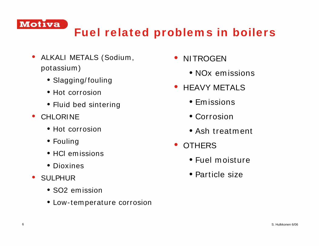
• ALKALI METALS (Sodium, potassium)
•Slagging/fouling
•Hot corrosion
•Fluid bed sintering
• CHLORINE
•Hot corrosion
•Fouling
•HCl emissions
•Dioxines
• SULPHUR
•SO2 emission
•Low-temperature corrosion
Fuel related problems in boilers
• NITROGEN
•NOx emissions
• HEAVY METALS
•Emissions
•Corrosion
•Ash treatment
• OTHERS
•Fuel moisture
•Particle size

7 S. Hulkkonen 6/06
Fuels sorted by harmful components
Fuel High alkaliNa+K
High chlorine High sulfur High moisture High ash
Plywood waste XForest residue XOlive pits XAspen bark XRubber tree XStraws X XReed canary grass (X) (X)REF XRDF X (X) (X)Bark XPeat (X) XBio-sludge X (X) X XPrimary-sludge X X

8 S. Hulkkonen 6/06
Slagging
Source: Miles
• Slagging – furnace

9 S. Hulkkonen 6/06
Fouling
Source: Miles
• Ash deposits on the heat transfer surfaces• Inertial impaction
• Thermophoresis
• Condesation
• Chemical reaction

10 S. Hulkkonen 6/06
Superheater foulingMECHANISM
• At low temperature melting components present in the flue gases impact and deposit on heat transfer surfaces
• Typically when amount of melt is 15-70%, ash is sticky. Corresponding temperatures T15 and T70.
• Typical sticky alkali compounds are (NaCl, KCl, Na2CO3, K2CO3)
• Aluminium is also highly problematic – melting temperature of metallic aluminiun 660 °C.
AFFECTING FACTORS
• Flue gas temperature
• Fuel bound Na, K, Cl, and Al
• High chlorine content decreases ash melting temperature
• S/Cl ratio determines the amount of free Cl.
• Alkalies (Na, K) increase the amount of melt
• High moisture assists HCl formation

11 S. Hulkkonen 6/06
Melting temperatures
Source: Miles

12 S. Hulkkonen 6/06
Ash melting (Chemkin-calculation)
0
5
10
15
20
25
500
525
550
575
600
625
650
675
700
725
750
775
800
825
850
875
900
925
950
975
1000
1025
1050
1075
1100
1125
1150
1175
1200
Temperature [C]
Am
ount
of m
elt [
wt%
]
Wood 50% - Olive pumace 50%Cl: 0,15 wt-% S/Cl: 0,68 (mole ratio)Alkali index: 0,36 kg alk.ox./GJNa2O: 1,71 wt-% of the ashK2O: 7,7 wt-% of the ashAsh: 7,88 wt-% of dsT0: 685 CT15: 960 C
Source: Hulkkonen

13 S. Hulkkonen 6/06
• Different indices are used to estimate the fouling behavior
• Alkali-index shows sodium and potassium content as related to fuel heating value
• (K2O+Na2O)/GCV (kg/GJ)
• Threshold value 0,17 kg/GJ, when fouling is probable and 0,34 kg/GJ when it is unavoidable
• Another index shows alkalies as related to silica
• (K2O+Na2O)/SiO2
• When larger than 1, fouling probable
• Slagging/fouling depends on many factors: indices are only tools for asessing the possible behaviour of ash
Source: Miles
Alkali-index

14 S. Hulkkonen 6/06
Furnace average temperatureBFB, Arvika
0,0
1,0
2,0
3,0
4,0
5,0
6,0
7,0
8,0
9,0
10,0
11,0
12,0
1100 1200 1300 1400 1500 1600
T/K, Average
Distance from bed surface (m)
FEGT

15 S. Hulkkonen 6/06
Boiler design criteria
• Flue gas temperature before the superheater less than T15. T15 means the temperature where 15% of the ash is in melted phase.
• Typically the temperatures 650 - 750 °C with difficult fuels and 900-950 °C with good fuels.
• Wide tube spacing• 120 mm when temperature > 600 °C
• 60 mm when temperature < 600 °C
• 40 mm in economiser area
• Efficient sootblowing - Tube bank thickness less than 1.5m
• Downwards gas flow to help soot blowing
• Additives for binding the alkalies

16 S. Hulkkonen 6/06
Corrosion• Furnace
• Reducing conditions
• Molten ash – components that stay molten in low
temperatures
• Superheaters – hot corrosion
• High temperature
• Chlorides – hot corrosion
• Fouling
• Last heat transfer surfaces – low temperature
corrosion
• Fuel sulphur and chlorine content
• Mainly dewpoint corrosion

17 S. Hulkkonen 6/06
Superheater hot corrosion• In combustion gaseous Cl, S, Na, K release to flue gases
• Alkali chlorides condense on the heat transfer surfaces – deposits
• In the deposit the chlorides react with sulphur dioxide in the flue gas releasing gaseous chlorine
• The alkali chlorides on the tube surface break the oxide layer protecting the tube
• Chlorine reacts with iron forming FeCl2
• Chlorine transfers iron (Fe) from the metal surface -> corrosion
• FeCl2 oxidices releasing Cl back to the deposit
• Threshold temperature for FeCl formation is 460 °C
• Strong corrosion may be experienced with biomass fuels when temperature higher than 480 °C and alkalimetals and chlorine in the fuel
• With steam temperature of 400-420 °C no chlorine based corrosion

18 S. Hulkkonen 6/06
Corrosion mechanism
Source: Riedl

19 S. Hulkkonen 6/06
Superheater materials
Lähde: Salmenoja

20 S. Hulkkonen 6/06
Corrosion protection in boilers
•SUPERHEATER
•Low flue gas temperature before superheater to avoid formation of tenacious deposits - cooling chamber and screens
•Wide tube spacing to reduce the gas velocity and fouling
•Low steam temperature to minimize the rate of corrosion (< 420 C)
•Co-current flow in the hottest superheater
•Corrosion resistant materials in the hottest superheaters (AC 66)
•High alloy shielding of the tubes in the sootblower area
•Avoid radiant superheaters
•According to studies
•Strong corrosion when S/Cl molar ratio below 2, moderate when S/Cl 2-4 and unlikely when S/Cl higher than 4
•Memory effect– Chlorine remains in the ”memory” of the metal

21 S. Hulkkonen 6/06
Boilers for biomass
• Grate fired boilers
• Fluidized bed boilers

22 S. Hulkkonen 6/06
Grate types• Fixed and mechanical grates
• Fixed grates in small units and mechanical in bigger plants
• Grate types
• Fixed plane grate
• Fixed inclined or step grate
• Underfeed grate
• Mechanical chain grate
• Mechanical inclined grate
• Grates are either air or watercooled. Water cooled typically
large and for high heating value fuels.
• Grates in Finland typically in small applications
• In Finland Wärtsilä supplies rotating grates – BioGrate

23 S. Hulkkonen 6/06
Grate firing principle
• Combustion
• Drying and heating
• Volatiles combustion
• Fixed carbon combustion
• Output limited by ignition- or combustion trate
• Grate surface area
• Coals 1-1.6 MW/m2
• Wet biomass, 60% 0.2-0.4 MW/m2
• Dry biomass, 30% 0.6-0.8 MW/m2

24 S. Hulkkonen 6/06
KABLITZ GRATES Kablitz grate
RECIPROCATING GRATE
The Detroit Reciprograte Stoker has met with wide approval for burning unprepared municipal and industrial solid waste as fuel.

25 S. Hulkkonen 6/06
Travelling grate
TRAVELLING GRATE
The Detroit RotoGrate stoker is a continuous ash discharge, traveling grate, spreader stoker that is perfect for a broad range of applications. It is recognized worldwide for its efficiency in generating steam and power from coal and refuse

26 S. Hulkkonen 6/06
VIBRATING GRATE
The spreader firing principle is the most widely accepted, proven and user friendly means of burning biomass fuels. Sized fuel is metered to a series of distribution devices which spread it uniformly over the stoker grate surface.
Fine particles of fuel are rapidly burned in suspension assisted by carefully designed overfire air turbulence systems. Coarser, heavier fuel particles are spread evenly on the grate forming a thin, fast-burning fuel bed. The combination of suspension and the fast-burning bed makes this method of firing extremely responsive to load demand.
Vibrating grate
27 S. Hulkkonen 6/06
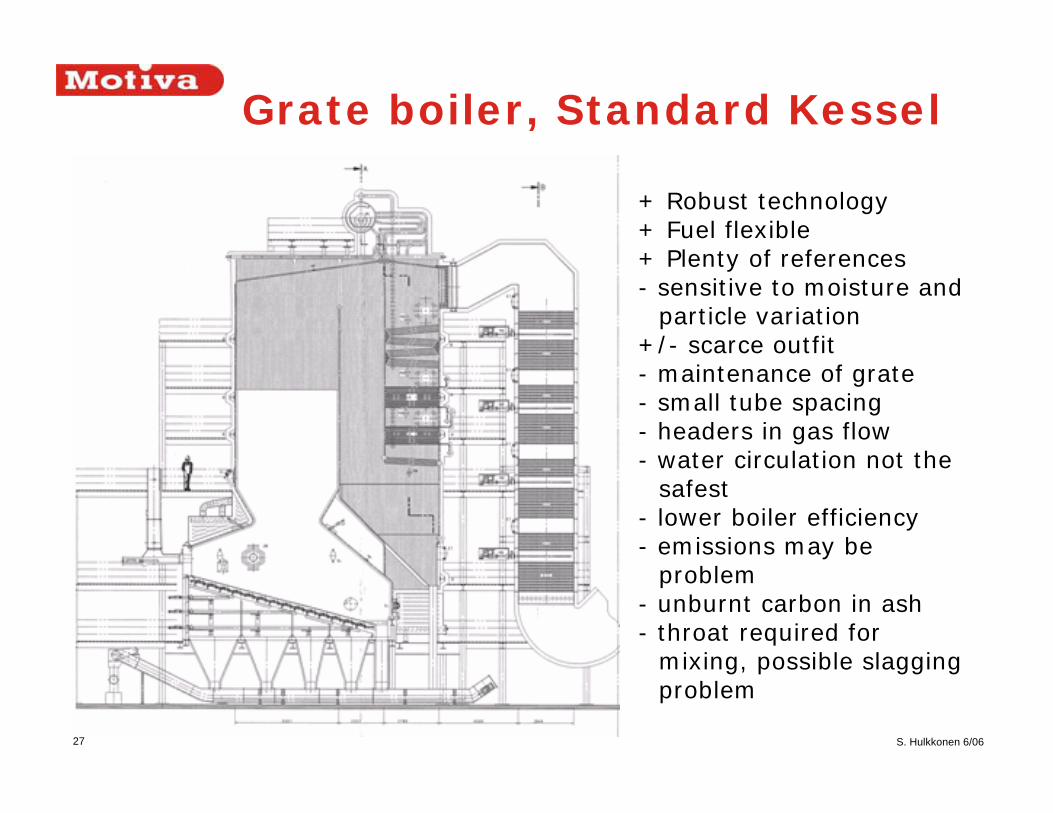
+ Robust technology+ Fuel flexible+ Plenty of references- sensitive to moisture and
particle variation+/- scarce outfit- maintenance of grate- small tube spacing- headers in gas flow- water circulation not the
safest- lower boiler efficiency- emissions may be
problem- unburnt carbon in ash- throat required for
mixing, possible slagging problem
Grate boiler, Standard Kessel

28 S. Hulkkonen 6/06
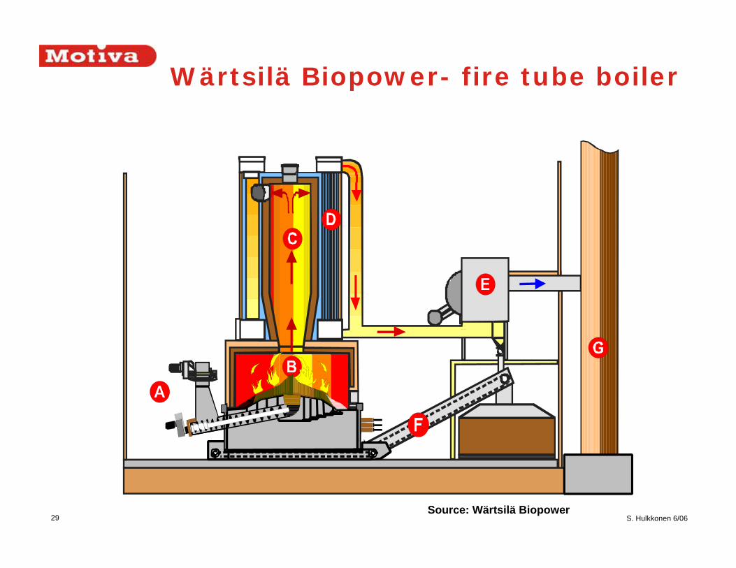
Biograte - Wärtsilä
- Wärtsiläsupplies grate boilers in size class of 3-20 MWth
• Conical, rotating grate
• Fuel feeding with stoker screw to the center of the grate
• 3-5 rotating grate rings
• 2-4 fixed grate rings
• Ash grate
• Wide grate area for complete combustion
• Flexible, controlled primary air distribution
• Wet bottom ash system
• Flue gas recirculation used for grate cooling
29 S. Hulkkonen 6/06
Wärtsilä Biopower- fire tube boiler
Source: Wärtsilä Biopower

30 S. Hulkkonen 6/06
Wärtsilä water tube boiler
Etupesä
Lieriö
I-tulistin
Lippuhöyrystin
EkoTulipesä
II-tulistin
Verho
SV-säiliö
PA-syöttö
Etupesä
Lieriö
I-tulistin
Lippuhöyrystin
EkoTulipesä
II-tulistin
Verho
SV-säiliö
PA-syöttö

31 S. Hulkkonen 6/06
Fluidized bed combustion•Fluidized bed combustion was introduced to energy
production in 1970’s and widened to biomass fuels in 1980’s
•In fluidized bed combustion inert bed material is fluidized by blowing air through the material layer
•Fuel is combusted inside or above the fluidizing bed
•The heat capacity of the fluidized bed maintains and evens out the combustion
•Benefits with biomass fuels•Fuel flexibility
•Efficient combustion
•Low emissions
•Bubbling fluidized bed best for biomass fuels
•Circulating fluidized bed when burning coal or high heating value biomass fuels
•Suppliers in Finland•Kvaerner (Metso), Foster Wheeler, Putkimaa, Noviter

32 S. Hulkkonen 6/06
Fluidized bed types
• BFB, Bubbling fluidized bed
• CFB, Circulating fluidized bed
Lähde: Huhtinen
FIXED BED BUBBLING BED CIRCULATING BED
Fluidizing velocity
log dp

33 S. Hulkkonen 6/06
Differences between BFB and CFB
BFB• bed material diameter 0.5-1.2mm• primary air flow 40%• fluidizing velocity 1-3 m/s• furnace loading 0.7-3 MW/m2• bed height 0.5 m• bed temperature 850 °C• furnace temperature 900-1000°C• best for high reactive fuels• sulphur removal 50%• suitable for boiler conversions• lower price than CFB• lower auxiliary power consumption• largest boilers abt. 300 MWth
CFB• bed material diameter 0.1-0.5 mm• primary air flow <40%• fluidizing velocity 4-8 m/s• furnace loading 0.7-5 MW/m2• bed temperature 850 °C• applicable to coal, 100 %• sulphur removal 90-95%• largest bioboilers abt. 500 MWth

34 S. Hulkkonen 6/06
Bed sinteringMECHANISM
• The alkali metal (Na, K) present in the fuel reacts on the surface of sand particles forming alkali silicates
• The surface of particles becomes gluish thus sticking particles together
• Results in disturbances in fluidisation, local hot spots and accelerating agglomeration
AFFECTING FACTORS
• Bed temperature
• Ash composition (Sodium and Potassium)
• Ratio between fuel and bed mass
POSSIBLE WAYS TO AVOID SINTERING
• Bed temperature decrease
• Continuous change of bed material
• Alternate bed materials
• Diabas, volcanic stone
• Additives
• Caolin

35 S. Hulkkonen 6/06
BFB by Kvaerner
Source: Salmenoja

36 S. Hulkkonen 6/06
Large BFB boiler by Kvaerner
Source: Salmenoja

37 S. Hulkkonen 6/06
Small ACZ- plant for waste fuels (by Kvaerner)
Source: Salmenoja

38 S. Hulkkonen 6/06
Large CFB - Kvaerner
Lähde: Salmenoja
39 S. Hulkkonen 6/06
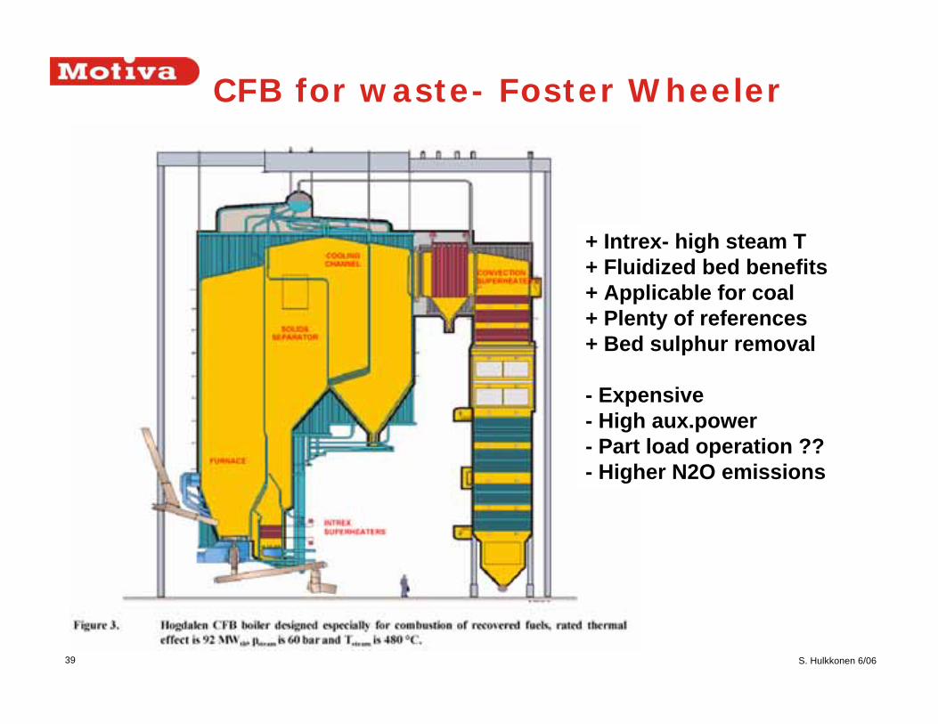
CFB for waste- Foster Wheeler
+ Intrex- high steam T+ Fluidized bed benefits+ Applicable for coal+ Plenty of references+ Bed sulphur removal
- Expensive- High aux.power- Part load operation ??- Higher N2O emissions

40 S. Hulkkonen 6/06
Gasification• In gasification process wood and other biomass
materials are gasified to produce so called
´producer gas´ for heat or electricity generation.
Gasification system consists of a gasifier unit,
purification system and energy converters - burner
or engine.
• Gasifier types
• Fixed bed gasifiers
Down draft
Up draft
• Fluidized bed gasifiers
• Entrained flow gasifiers

41 S. Hulkkonen 6/06
Gasifier types
Ud
Dd

42 S. Hulkkonen 6/06
Fluidized bed gasifiers

43 S. Hulkkonen 6/06
Gasifier applications
Source: Rensfelt/Synbios 2005

44 S. Hulkkonen 6/06
Summary
• Biomass fuels
• High volatile content – good combustion
• Slagging and fouling may be a problem with high alkali
fuels
• Hot corrosion with high chlorine fuels
• In Finland fluidized bed combustion is
dominating in peat and wood fired boilers
• Grate firing in smaller size scale applications
• Gasifiers under development
• Fixed bed gasifiers in small size scale
• Higher power-to heat ratio as main benefit