057003i.fm Page 134 Tuesday, March 11, 2003 2:14 PM certification but to all industry...
20
Transcript of 057003i.fm Page 134 Tuesday, March 11, 2003 2:14 PM certification but to all industry...

057003i.fm Page 134 Tuesday, March 11, 2003 2:14 PM

C
H
A
P
T
E
R
3
Shooting Trouble with IP
This chapter focuses on a number of objectives falling under the CCNP Troubleshooting guidelines. Understanding basic TCP/IP troubleshooting principles not only applies to the CCNP certification but to all industry certifications. A solid understanding of how IP works is essential for troubleshooting any small, medium, or large network.
This chapter and the remaining chapters assume knowledge of the previous chapters, which deal conceptually with protocol characteristics, models, troubleshooting methods, support tools, and resources. Each chapter starts by introducing a hands-on chapter scenario. To gain practical experience, build the network in the scenario if at all possible and follow along. If that isn’t possible, the content and explanations are detailed enough for you to learn from without needing the equipment in front of you. Several integrated walk-through scenarios and Trouble Tickets enable you to benefit from the added learning advantages offered by practical application. After the Shooting Trouble with IP scenario, I explore TCP/IP concepts, symptoms, problems, and action plans.
This chapter covers the following topics:
•
Scenario: Shooting Trouble with IP
•
Protocols and Packets
•
Addressing
•
Routing Protocols
•
Trouble Tickets
•
Trouble Tickets Solutions
Supporting Website Files
You can find files and links to utilities that support this book on the Cisco Press website at www.ciscopress.com/1587200570. Even if you do not have a lab, you can take advantage of the supporting configuration files including the logs to understand device input and output. The files are listed throughout the chapters in italics.
In order to be able to read and work with some of the supporting files offered at www.ciscopress.com/1587200570, you may want to download some of the programs listed
in Table I-1 in the Introduction.
057003i.fm Page 135 Tuesday, March 11, 2003 2:14 PM
136
Chapter 3: Shooting Trouble with IP
Scenario: Shooting Trouble with IP
It is now time to get started with the practical Shooting Trouble with IP scenario. First, add the additional equipment, perform a
write erase
or
erase startup-config
to clear your configurations from previous labs, and rewire according to Figure 3-1.
NOTE
My lab uses the 2514, 2501, 3640, 3620, and 2516 Cisco routers, but yours can include any number of devices that have similar interfaces. See Appendix C, “Equipment Reference,” for
the hardware used throughout the book.
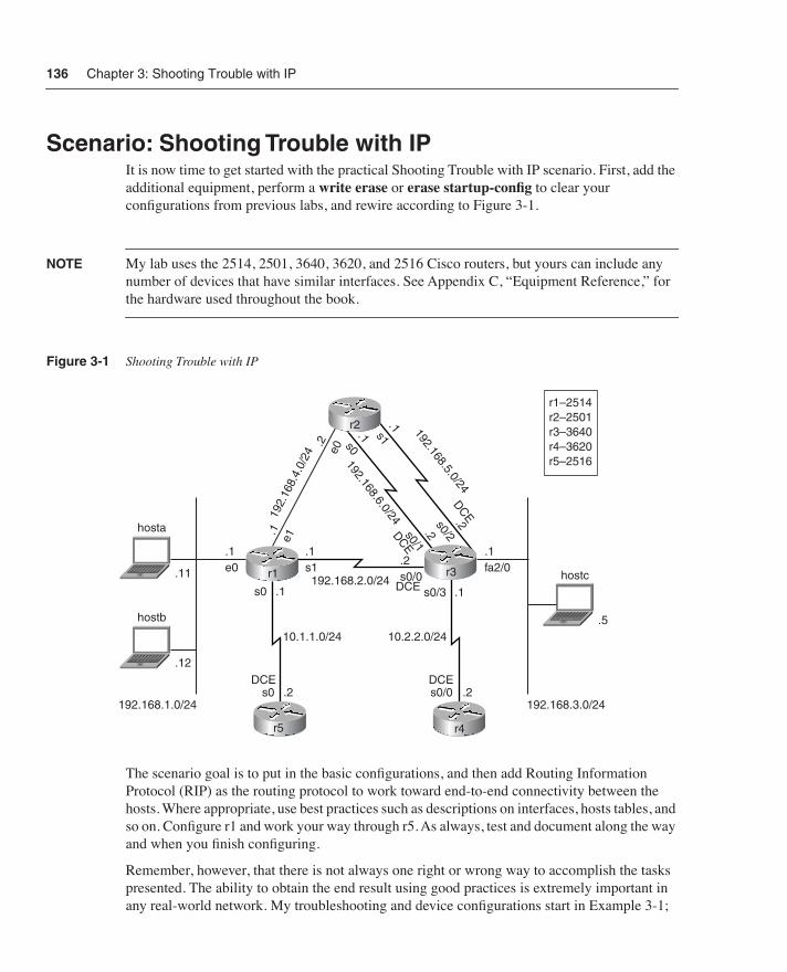
Figure 3-1
Shooting Trouble with IP
The scenario goal is to put in the basic configurations, and then add Routing Information Protocol (RIP) as the routing protocol to work toward end-to-end connectivity between the hosts. Where appropriate, use best practices such as descriptions on interfaces, hosts tables, and so on. Configure r1 and work your way through r5. As always, test and document along the way and when you finish configuring.
Remember, however, that there is not always one right or wrong way to accomplish the tasks presented. The ability to obtain the end result using good practices is extremely important in any real-world network. My troubleshooting and device configurations start in Example 3-1;
192.168.2.0/24
192.
168.
4.0/
24
10.1.1.0/24 10.2.2.0/24
192.168.1.0/24 192.168.3.0/24
hosta
.1 .1e0
.1s0 .1s0/3
s1.2
.1
s0/0fa2/0.11
hostb
.12
.2s0DCE DCE
DCE
.2s0/0
hostc
.5
.1e1
.2e0
192.168.5.0/24
.1s1
.2s0/2
192.168.6.0/24
.1s0
.2s0/1
DCE
DCE
r1–2514r2–2501r3–3640r4–3620r5–2516
r1 r3
r5 r4
r2
057003i.fm Page 136 Tuesday, March 11, 2003 2:14 PM
Scenario: Shooting Trouble with IP
137
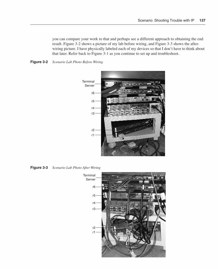
you can compare your work to that and perhaps see a different approach to obtaining the end result. Figure 3-2 shows a picture of my lab before wiring, and Figure 3-3 shows the after-wiring picture. I have physically labeled each of my devices so that I don’t have to think about that later. Refer back to Figure 3-1 as you continue to set up and troubleshoot.
Figure 3-2
Scenario Lab Photo Before Wiring
Figure 3-3
Scenario Lab Photo After Wiring
Terminal Server
r6
r5
r4
r3
r2
r1
Terminal Server
r6
r5
r4
r3
r2r1
057003i.fm Page 137 Tuesday, March 11, 2003 2:14 PM
138
Chapter 3: Shooting Trouble with IP
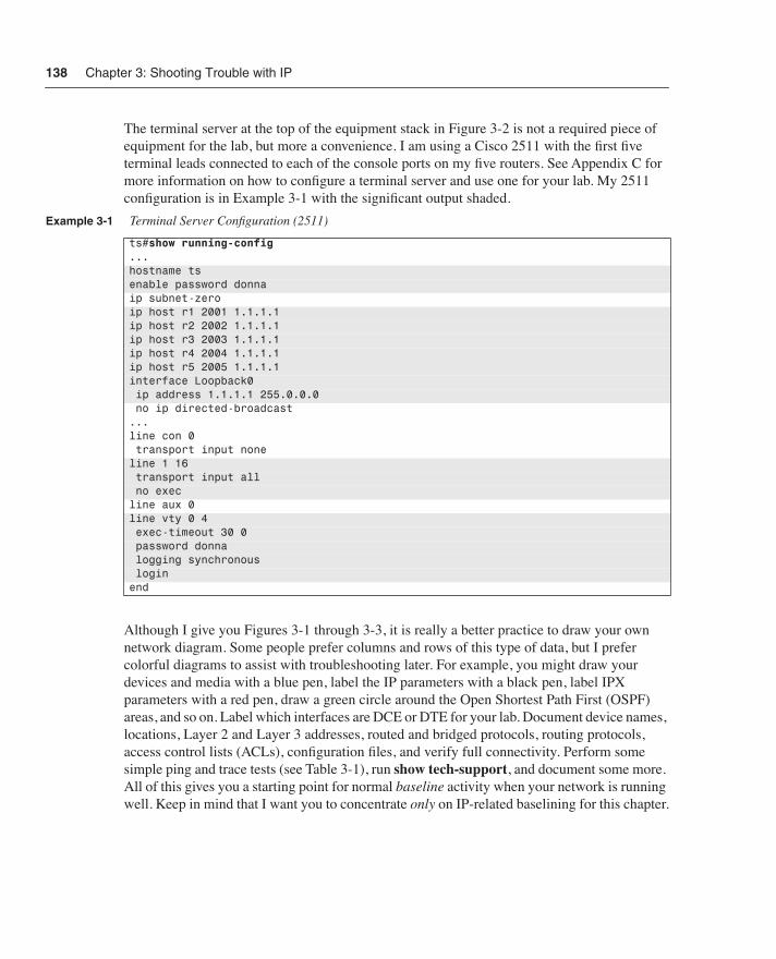
The terminal server at the top of the equipment stack in Figure 3-2 is not a required piece of equipment for the lab, but more a convenience. I am using a Cisco 2511 with the first five terminal leads connected to each of the console ports on my five routers. See Appendix C for more information on how to configure a terminal server and use one for your lab. My 2511 configuration is in Example 3-1 with the significant output shaded.
Although I give you Figures 3-1 through 3-3, it is really a better practice to draw your own network diagram. Some people prefer columns and rows of this type of data, but I prefer colorful diagrams to assist with troubleshooting later. For example, you might draw your devices and media with a blue pen, label the IP parameters with a black pen, label IPX parameters with a red pen, draw a green circle around the Open Shortest Path First (OSPF) areas, and so on. Label which interfaces are DCE or DTE for your lab. Document device names, locations, Layer 2 and Layer 3 addresses, routed and bridged protocols, routing protocols, access control lists (ACLs), configuration files, and verify full connectivity. Perform some simple ping and trace tests (see Table 3-1), run
show tech-support
, and document some more. All of this gives you a starting point for normal
baseline
activity when your network is running well. Keep in mind that I want you to concentrate
only
on IP-related baselining for this chapter.
Example 3-1
Terminal Server Configuration (2511)
ts#
show running-config
...hostname tsenable password donnaip subnet-zeroip host r1 2001 1.1.1.1ip host r2 2002 1.1.1.1ip host r3 2003 1.1.1.1ip host r4 2004 1.1.1.1ip host r5 2005 1.1.1.1interface Loopback0 ip address 1.1.1.1 255.0.0.0 no ip directed-broadcast...line con 0 transport input noneline 1 16 transport input all no execline aux 0line vty 0 4 exec-timeout 30 0 password donna logging synchronous loginend
057003i.fm Page 138 Tuesday, March 11, 2003 2:14 PM
Scenario: Shooting Trouble with IP
139
NOTE
You will adjust your hands-on lab for new equipment, software, protocols, media, services, problems, and so on as you progress through various Trouble Tickets and chapters. Feel free to substitute whatever equipment you have for the hosts, routers, and switches in Figure 3-1. All
2600s and 3600s, or better yet all 6500s, would be nice, but that isn’t what I have either.
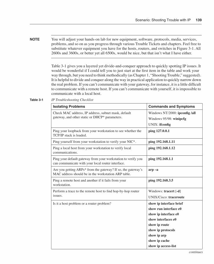
Table 3-1 gives you a layered yet divide-and-conquer approach to quickly spotting IP issues. It would be wonderful if I could tell you to just start at the first item in the table and work your way through, but you need to think methodically (as Chapter 1, “Shooting Trouble,” suggested). It is helpful to divide and conquer along the way in practical application to quickly narrow down the real problem. If you can’t communicate with your gateway, for instance, it is a little difficult to communicate with a remote host. If you can’t communicate with yourself, it is impossible to communicate with a local host.
Table 3-1
IP Troubleshooting Checklist
Isolating Problems Commands and Symptoms
Check MAC address, IP address, subnet mask, default gateway, and other static or DHCP* parameters.
Windows NT/2000:
ipconfig /all
Windows 95/98:
winipcfg
UNIX:
ifconfig
Ping your loopback from your workstation to see whether the TCP/IP stack is loaded.
ping 127.0.0.1
Ping yourself from your workstation to verify your NIC*.
ping 192.168.1.11
Ping a local host from your workstation to verify local communications.
ping 192.168.1.12
Ping your default gateway from your workstation to verify you can communicate with your local router interface.
ping 192.168.1.1
Are you getting ARPs* from the gateway? If so, the gateway’s MAC address should be in the workstation ARP table.
arp –a
Ping a remote host and another if it fails from your workstation.
ping 192.168.3.5
Perform a trace to the remote host to find hop-by-hop router issues.
Windows:
tracert
[
-d
]
UNIX/Cisco:
traceroute
Is it a host problem or a router problem?
show ip interface brief
show run interface e0
show ip interface e0
show interfaces e0
show ip route
show ip protocols
show ip arp
show ip cache
show ip access-list
continues
057003i.fm Page 139 Tuesday, March 11, 2003 2:14 PM
140
Chapter 3: Shooting Trouble with IP
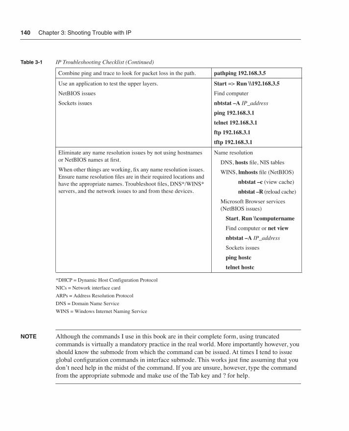
*DHCP = Dynamic Host Configuration Protocol
NICs = Network interface card
ARPs = Address Resolution Protocol
DNS = Domain Name Service
WINS = Windows Internet Naming Service
NOTE
Although the commands I use in this book are in their complete form, using truncated commands is virtually a mandatory practice in the real world. More importantly however, you should know the submode from which the command can be issued. At times I tend to issue global configuration commands in interface submode. This works just fine assuming that you don’t need help in the midst of the command. If you are unsure, however, type the command
from the appropriate submode and make use of the Tab key and ? for help.
Combine ping and trace to look for packet loss in the path.
pathping 192.168.3.5
Use an application to test the upper layers.
NetBIOS issues
Sockets issues
Start
=>
Run
\\192.168.3.5
Find computer
nbtstat –A
IP_address
ping 192.168.3.1
telnet 192.168.3.1
ftp 192.168.3.1
tftp 192.168.3.1
Eliminate any name resolution issues by not using hostnames or NetBIOS names at first.
When other things are working, fix any name resolution issues. Ensure name resolution files are in their required locations and have the appropriate names. Troubleshoot files, DNS*/WINS* servers, and the network issues to and from these devices.
Name resolution
DNS,
hosts
file, NIS tables
WINS,
lmhosts
file (NetBIOS)
nbtstat –c
(view cache)
nbtstat –R
(reload cache)
Microsoft Browser services (NetBIOS issues)
Start
,
Run
\\computername
Find computer or
net view
nbtstat –A
IP_address
Sockets issues
ping hostc
telnet hostc
Table 3-1
IP Troubleshooting Checklist (Continued)
057003i.fm Page 140 Tuesday, March 11, 2003 2:14 PM

Scenario: Shooting Trouble with IP
141
Using the scenario diagram in Figure 3-1, configure r1 similar to what is in Example 3-2. My r1 is a Cisco 2514, but you can use any Cisco router that has two Ethernet interfaces and two serial interfaces for the lab. My passwords are all donna because that is easy to remember for the labs, but that is exactly why they should not all be donna for practical application. Throughout the following examples, I have made a few careless mistakes that you may or may not make. I will troubleshoot them when all my routers are configured per the scenario diagram.
Example 3-2
r1 Configuration (2514)
Router>
enable
Router#
configure terminal
Enter configuration commands, one per line. End with CNTL/Z.Router(config)#
hostname r1
r1(config)#
enable password donna
r1(config)#
line vty 0 4
r1(config-line)#
login
r1(config-line)#
password donna
r1(config-line)#
exit
r1(config)#
interface ethernet 0
r1(config-if)#
description e0 to hosta and hostb
r1(config-if)#
ip address 192.168.1.1 255.255.255.0
r1(config-if)#
no shut
00:10:12: %LINK-3-UPDOWN: Interface Ethernet0, changed state to up 00:10:13: %LINEPROTO-5-UPDOWN: Line protocol on Interface Ethernet0, changed state to upr1(config)#
interface ethernet 1
r1(config-if)#
description e1 to r2e0
r1(config-if)#
ip address 192.168.4.1 255.255.255.0
r1(config-if)#
no shut
r1(config-if)#
interface serial 0
r1(config-if)#
description s0 to r5s0
r1(config-if)#
ip address 10.1.1.1 255.255.255.0
r1(config-if)#
bandwidth 64r1(config-if)#no shut00:13:11: %LINK-3-UPDOWN: Interface Serial0, changed state to downr1(config-if)#ip host r1 192.168.1.1 192.168.2.1 192.168.4.1 10.1.1.1r1(config)#ip host r2 192.168.4.2 192.168.5.1 192.168.6.1r1(config)#$192.168.2.2 192.168.5.2 192.168.6.2 192.168.3.1 10.2.2.1r1(config)#ip host r4 10.2.2.2r1(config)#ip host r5 10.1.1.2r1(config)#router ripr1(config-router)#network 192.168.1.0r1(config-router)#network 192.168.2.0r1(config-router)#network 192.168.4.0r1(config-router)#network 10.1.1.0r1(config-router)#endr1#copy running-config startup-config
057003i.fm Page 141 Tuesday, March 11, 2003 2:14 PM

142 Chapter 3: Shooting Trouble with IP
NOTE For the first router configuration, I illustrate the enable command to take you into enable mode Router# and the configure terminal command to take you to the global configuration mode Router(config)#, where the Cisco output reminds you that you can press Ctrl+Z to return to enable mode from any prompt. Alternatively, you can type end to return to the privileged prompt (enable mode) or exit to back up one level at a time. I will assume from this point on that you are very comfortable with entering and exiting these modes and therefore I will eliminate the initial enable and configure terminal commands from my examples.
NOTE Remember that the dollar sign ($) at the beginning of a line of user input is the Cisco IOS indication that the text was too much for the width of the terminal screen. You can always press Ctrl+A to get to the beginning or Ctrl+E to get to the end of a line.
Now move on to configuring r2 as in Example 3-3. My r2 is a Cisco 2501, but you can use any Cisco router that has at least one Ethernet interface and two serial interfaces for the lab. I copied the hosts table lines from r1 and pasted them into this configuration. In future examples, I plan to just paste the configuration for the hosts table and passwords to save a little typing.
Example 3-3 r2 Configuration (2501)
Router(config)#hostname r2r2(config)#enable password donnar2(config)#line vty 0 4r2(config-line)#loginr2(config-line)#password donnar2(config-line)#exitr2(config)#interface ethernet 0r2(config-if)#description e0 to r1e1r2(config-if)#ip address 192.168.4.2 255.255.255.0r2(config-if)#no shutr2(config-if)#int 00:41:44: %LINK-3-UPDOWN: Interface Ethernet0, changed state to up00:41:45: %LINEPROTO-5-UPDOWN: Line protocol on Interface Ethernet0, changed state to ups0r2(config-if)#description s0 to r3s0/1r2(config-if)#bandwidth 64r2(config-if)#ip address 192.168.6.1 255.255.255.0r2(config-if)#no shut00:42:22: %LINK-3-UPDOWN: Interface Serial0, changed state to downr2(config-if)#interface serial 1r2(config-if)#description s1 to r3s0/2r2(config-if)#bandwidth 64r2(config-if)#ip address 192.168.5.1 255.255.255.0r2(config-if)#router ripr2(config-router)#network 192.168.4.0r2(config-router)#network 192.168.5.0
057003i.fm Page 142 Tuesday, March 11, 2003 2:14 PM

Scenario: Shooting Trouble with IP 143
NOTE The shaded output may appear a little confusing in text and is quite annoying in practice. Had I turned on logging synchronous, my input would not have been interrupted. You should do this for your configurations.
Configure the rest of your routers now and check your work using the following examples. I copied the text in Example 3-4 to Windows Notepad to easily paste it into r3, r4, and r5.
Example 3-5 and Example 3-6 start my r3 configuration. My r3 is a Cisco 3640, but you can use any Cisco router that has at least one Ethernet interface and four serial interfaces for the lab. Although the capabilities are not important in this chapter, having multiple serial interfaces on a router enables you to set up your own Frame Relay switch later in the book. Depending on the capabilities, the Fast Ethernet interface will give you an opportunity to experiment with duplex and speed concepts as well.
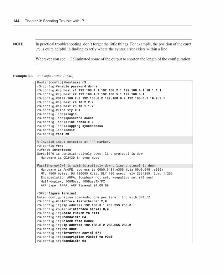
Note in Example 3-5 that I attempted to configure the e0 interface when it was really fa2/0 that I needed to configure. A physical inspection of the device confirmed that the Fast Ethernet port was located in Slot 2; because you can’t physically see my device, however, I proceeded with the show interfaces command.
r2(config-router)#network 192.168.6.0r2(config-router)#exitr2(config)#ip host r1 192.168.1.1 192.168.2.1 192.168.4.1 10.1.1.1r2(config)#ip host r2 192.168.4.2 192.168.5.1 192.168.6.1r2(config)#$192.168.2.2 192.168.5.2 192.168.6.2 192.168.3.1 10.2.2.1r2(config)#ip host r4 10.2.2.2r2(config)#ip host r5 10.1.1.2r2(config)#endr2#copy running-config startup-config
Example 3-4 Notepad File Including Passwords and Hosts Table
eeeennnnaaaabbbblllleeee ppppaaaasssssssswwwwoooorrrrdddd ddddoooonnnnnnnnaaaaiiiipppp hhhhoooosssstttt rrrr1111 111199992222....111166668888....1111....1111 111199992222....111166668888....2222....1111 111199992222....111166668888....4444....1111 11110000....1111....1111....1111iiiipppp hhhhoooosssstttt rrrr2222 111199992222....111166668888....4444....2222 111199992222....111166668888....5555....1111 111199992222....111166668888....6666....1111iiiipppp hhhhoooosssstttt rrrr3333 111199992222....111166668888....2222....2222 111199992222....111166668888....5555....2222 111199992222....111166668888....6666....2222 111199992222....111166668888....3333....1111 11110000....2222....2222....1111iiiipppp hhhhoooosssstttt rrrr4444 11110000....2222....2222....2222iiiipppp hhhhoooosssstttt rrrr5555 11110000....1111....1111....2222lllliiiinnnneeee vvvvttttyyyy 0000 4444llllooooggggiiiinnnnppppaaaasssssssswwwwoooorrrrdddd ddddoooonnnnnnnnaaaalllliiiinnnneeee ccccoooonnnnssssoooolllleeee 0000llllooooggggggggiiiinnnngggg ssssyyyynnnncccchhhhrrrroooonnnnoooouuuusssseeeexxxxiiiitttt
Example 3-3 r2 Configuration (2501) (Continued)
057003i.fm Page 143 Tuesday, March 11, 2003 2:14 PM
144 Chapter 3: Shooting Trouble with IP
NOTE In practical troubleshooting, don’t forget the little things. For example, the position of the caret (^) is quite helpful in finding exactly where the syntax error exists within a line.
Wherever you see ... I eliminated some of the output to shorten the length of the configuration.
Example 3-5 r3 Configuration (3640)
Router(config)#hostname r3r3(config)#enable password donnar3(config)#ip host r1 192.168.1.1 192.168.2.1 192.168.4.1 10.1.1.1r3(config)#ip host r2 192.168.4.2 192.168.5.1 192.168.6.1r3(config)#$192.168.2.2 192.168.5.2 192.168.6.2 192.168.3.1 10.2.2.1r3(config)#ip host r4 10.2.2.2r3(config)#ip host r5 10.1.1.2r3(config)#line vty 0 4r3(config-line)#loginr3(config-line)#password donnar3(config-line)#line console 0r3(config-line)#logging synchronousr3(config-line)#exitr3(config)#int e0 ^% Invalid input detected at ’^’ marker.r3(config)#endr3#show interfacesSerial0/0 is administratively down, line protocol is down Hardware is CD2430 in sync mode...FastEthernet2/0 is administratively down, line protocol is down Hardware is AmdFE, address is 00b0.6481.e300 (bia 00b0.6481.e300) MTU 1500 bytes, BW 100000 Kbit, DLY 100 usec, rely 255/255, load 1/255 Encapsulation ARPA, loopback not set, keepalive set (10 sec) Half-duplex, 100Mb/s, 100BaseTX/FX ARP type: ARPA, ARP Timeout 04:00:00...r3#configure terminalEnter configuration commands, one per line. End with CNTL/Z.r3(config)#interface fastethernet 2/0r3(config-if)#ip address 192.168.3.1 255.255.255.0r3(config-router)#iiiinnnntttteeeerrrrffffaaaacccceeee sssseeeerrrriiiiaaaallll 0000////0000r3(config-if)#ddddeeeesssscccc rrrr3333ssss0000////0000 ttttoooo rrrr1111ssss1111r3(config-if)#bbbbaaaannnnddddwwwwiiiiddddtttthhhh 66664444r3(config-if)#cccclllloooocccckkkk rrrraaaatttteeee 66664444000000000000r3(config-if)#iiiipppp aaaaddddddddrrrreeeessssssss 111199992222....111166668888....2222....2222 222255555555....222255555555....222255555555....0000r3(config-if)#nnnnoooo sssshhhhuuuuttttr3(config-if)#iiiinnnntttteeeerrrrffffaaaacccceeee sssseeeerrrriiiiaaaallll 0000////1111r3(config-if)#ddddeeeessssccccrrrriiiippppttttiiiioooonnnn rrrr3333ssss0000////1111 ttttoooo rrrr2222ssss0000r3(config-if)#bbbbaaaannnnddddwwwwiiiiddddtttthhhh 66664444
057003i.fm Page 144 Tuesday, March 11, 2003 2:14 PM

Scenario: Shooting Trouble with IP 145
Finish configuring r3, r4, and r5 and test your configurations.
Now that you have configured your lab, perform some basic lower-layer tests to verify your drawing and your internetwork. Make sure all used interfaces are in a line protocol up state as in Example 3-6; if they are not in a line protocol up state, fix any noticeable problems at this point. Notice how show ip interface brief is a very appropriate command to quickly spot lower-level issues.
r3(config-if)#cccclllloooocccckkkk rrrraaaatttteeee 66664444000000000000r3(config-if)#iiiipppp aaaaddddddddrrrreeeessssssss 111199992222....111166668888....6666....2222 222255555555....222255555555....222255555555....0000r3(config-if)#nnnnoooo sssshhhhuuuuttttr3(config-if)#iiiinnnntttteeeerrrrffffaaaacccceeee sssseeeerrrriiiiaaaallll 0000////2222r3(config-if)#ddddeeeessssccccrrrriiiippppttttiiiioooonnnn rrrr3333ssss0000////2222 ttttoooo rrrr2222ssss1111r3(config-if)#bbbbaaaannnnddddwwwwiiiiddddtttthhhh 66664444r3(config-if)#cccclllloooocccckkkk rrrraaaatttteeee 66664444000000000000r3(config-if)#iiiipppp aaaaddddddddrrrreeeessssssss 111199992222....111166668888....5555....2222 222255555555....222255555555....222255555555....0000r3(config-if)#nnnnoooo sssshhhhuuuutttt
Example 3-6 IP Interface Testing
r1>show ip interface briefInterface IP-Address OK? Method Status ProtocolEthernet0 192.168.1.1 YES NVRAM up up Ethernet1 192.168.4.1 YES manual up up Serial0 10.1.1.1 YES NVRAM up up Serial1 unassigned YES unset administratively down down r2>show ip interface briefInterface IP-Address OK? Method Status ProtocolEthernet0 192.168.4.2 YES NVRAM up up Serial0 192.168.6.1 YES NVRAM up up Serial1 192.168.5.1 YES NVRAM administratively down down r3>show ip interface briefInterface IP-Address OK? Method Status ProtocolSerial0/0 192.168.2.2 YES unset down down Serial0/1 192.168.6.2 YES unset up up Serial0/2 192.168.5.2 YES unset down down Serial0/3 unassigned YES unset down down ...FastEthernet2/0 192.168.3.1 YES manual up down r4>show ip interface briefInterface IP-Address OK? Method Status ProtocolEthernet0/0 unassigned YES unset administratively down down Serial0/0 10.2.2.2 YES manual down down Serial0/1 unassigned YES unset administratively down down r5>sh ip int brie Interface IP-Address OK? Method Status ProtocolBRI0 unassigned YES unset administratively down down BRI0:1 unassigned YES unset administratively down down BRI0:2 unassigned YES unset administratively down down Ethernet0 unassigned YES unset administratively down down Serial0 10.1.1.2 YES manual up up Serial1 unassigned YES unset administratively down down
Example 3-5 r3 Configuration (3640) (Continued)
057003i.fm Page 145 Tuesday, March 11, 2003 2:14 PM
146 Chapter 3: Shooting Trouble with IP
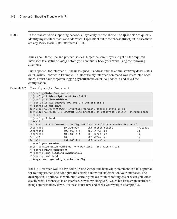
NOTE In the real world of supporting networks, I typically use the shortcut sh ip int brie to quickly identify my interface status and addresses. I spell brief out to the cheese (brie) just in case there are any ISDN Basic Rate Interfaces (BRI).
Think about these line and protocol issues. Target the lower layers to get all the required interfaces to a status of up/up before you continue. Check your work using the following examples.
First I spotted, for interface s1, the unassigned IP address and the administratively down status on r1, which I correct in Example 3-7. Because my interface command was interrupted once more, I must have forgotten logging synchronous on r1, so I added it and saved the configuration.
The r1s1 interface would have come up fine without the bandwidth statement, but it is optimal for routing protocols to configure the correct bandwidth statement on your interfaces. The description is optional as well, but it certainly makes troubleshooting easier when you know exactly what is connected to an interface. Now move along to r2, which has issues with interface s1 being administratively down. Fix these issues now and check your work in Example 3-8.
Example 3-7 Correcting Interface Issues on r1
r1(config)#interface serial 1r1(config-if)#description s1 to r3s0/0r1(config-if)#bandwidth 64r1(config-if)#ip address 192.168.2.1 255.255.255.0r1(config-if)#no shut05:16:39: %LINK-3-UPDOWN: Interface Serial1, changed state to up05:16:40: %LINEPROTO-5-UPDOWN: Line protocol on Interface Serial1, changed state to upr1(config-if)#endr1#sh i05:16:50: %SYS-5-CONFIG_I: Configured from console by consolep int briefInterface IP-Address OK? Method Status ProtocolEthernet0 192.168.1.1 YES NVRAM up up Ethernet1 192.168.4.1 YES manual up up Serial0 10.1.1.1 YES NVRAM up up Serial1 192.168.2.1 YES manual up up r1#configure terminal Enter configuration commands, one per line. End with CNTL/Z.r1(config)#line console 0r1(config-line)#logging synchronous r1(config-line)#endr1#copy running-config startup-config
057003i.fm Page 146 Tuesday, March 11, 2003 2:14 PM

Scenario: Shooting Trouble with IP 147
r3 requires you to look at your drawing more closely so that you can concentrate on just the interfaces being used. Configure any missing IP addresses and issue a no shut command on any used interfaces that are showing as administratively down. Check the status of the interfaces in Example 3-9.
Example 3-9 indicates that a problem still exists with s0/3 and fa2/0. The other end (host) is not running for my Ethernet hostc connection, but you need to examine further the cause of the down/down status for s0/3. Think about what’s in your tool bag from the preceding chapter to assist you further in spotting lower-layer problems. Check your thoughts against Example 3-10.
Everything looks normal on the r3 end of things from a physical point of view, so now investigate the other end of the connection as in Example 3-11.
Example 3-8 Correcting Interface Issues on r2
r2(config)#interface serial 1r2(config-if)#no shut05:20:08: %LINK-3-UPDOWN: Interface Serial1, changed state to up05:20:09: %LINEPROTO-5-UPDOWN: Line protocol on Interface Serial1, changed state to upr2(config-if)#endr2#show ip interface briefInterface IP-Address OK? Method Status ProtocolEthernet0 192.168.4.2 YES NVRAM up up Serial0 192.168.6.1 YES NVRAM up up Serial1 192.168.5.1 YES NVRAM up up r2#copy running-config startup-config
Example 3-9 Correcting Interface Issues on r3
r3#show ip interface briefInterface IP-Address OK? Method Status ProtocolSerial0/0 192.168.2.2 YES manual up up Serial0/1 192.168.6.2 YES manual up up Serial0/2 192.168.5.2 YES manual up up Serial0/3 unassigned YES manual down down ...FastEthernet2/0 192.168.3.1 YES manual up down
Example 3-10 Correcting Physical Issues on r3
r3#show controllers serial 0/3CD2430 Slot 0, Port 3, Controller 0, Channel 3, Revision 15Channel mode is synchronous serial idb 0x6129A1A0, buffer size 1524, V.35 DTE cable...
057003i.fm Page 147 Tuesday, March 11, 2003 2:14 PM
148 Chapter 3: Shooting Trouble with IP
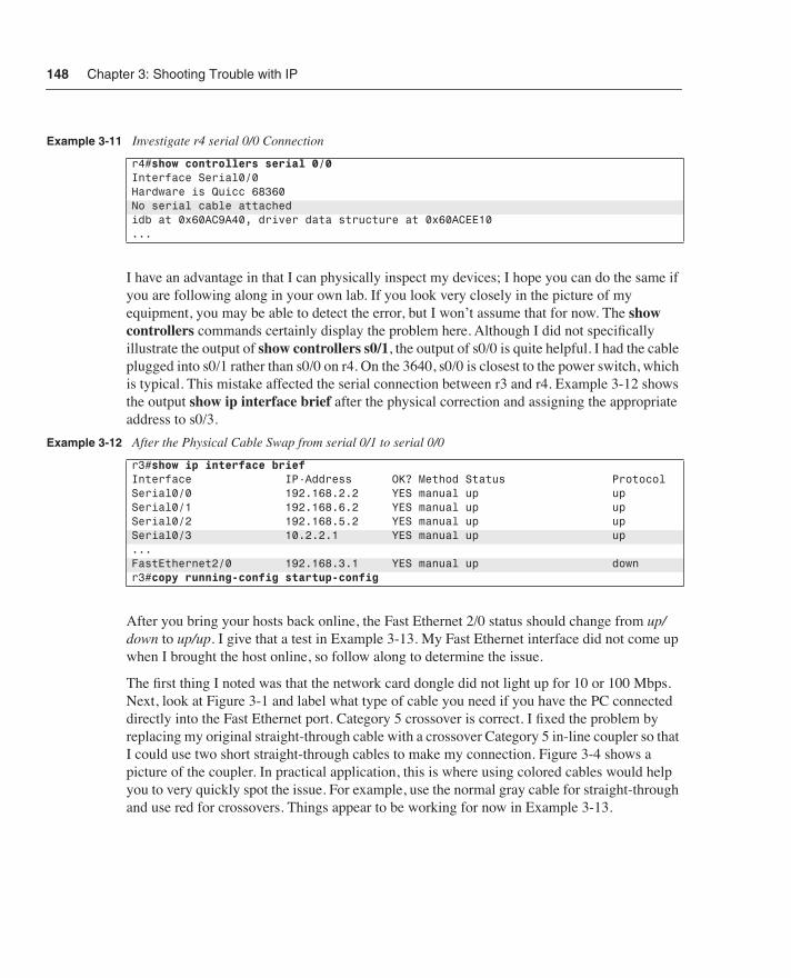
I have an advantage in that I can physically inspect my devices; I hope you can do the same if you are following along in your own lab. If you look very closely in the picture of my equipment, you may be able to detect the error, but I won’t assume that for now. The show controllers commands certainly display the problem here. Although I did not specifically illustrate the output of show controllers s0/1, the output of s0/0 is quite helpful. I had the cable plugged into s0/1 rather than s0/0 on r4. On the 3640, s0/0 is closest to the power switch, which is typical. This mistake affected the serial connection between r3 and r4. Example 3-12 shows the output show ip interface brief after the physical correction and assigning the appropriate address to s0/3.
After you bring your hosts back online, the Fast Ethernet 2/0 status should change from up/down to up/up. I give that a test in Example 3-13. My Fast Ethernet interface did not come up when I brought the host online, so follow along to determine the issue.
The first thing I noted was that the network card dongle did not light up for 10 or 100 Mbps. Next, look at Figure 3-1 and label what type of cable you need if you have the PC connected directly into the Fast Ethernet port. Category 5 crossover is correct. I fixed the problem by replacing my original straight-through cable with a crossover Category 5 in-line coupler so that I could use two short straight-through cables to make my connection. Figure 3-4 shows a picture of the coupler. In practical application, this is where using colored cables would help you to very quickly spot the issue. For example, use the normal gray cable for straight-through and use red for crossovers. Things appear to be working for now in Example 3-13.
Example 3-11 Investigate r4 serial 0/0 Connection
r4#show controllers serial 0/0Interface Serial0/0Hardware is Quicc 68360No serial cable attachedidb at 0x60AC9A40, driver data structure at 0x60ACEE10...
Example 3-12 After the Physical Cable Swap from serial 0/1 to serial 0/0
r3#show ip interface briefInterface IP-Address OK? Method Status ProtocolSerial0/0 192.168.2.2 YES manual up up Serial0/1 192.168.6.2 YES manual up up Serial0/2 192.168.5.2 YES manual up up Serial0/3 10.2.2.1 YES manual up up ...FastEthernet2/0 192.168.3.1 YES manual up down r3#copy running-config startup-config
057003i.fm Page 148 Tuesday, March 11, 2003 2:14 PM

Scenario: Shooting Trouble with IP 149
Figure 3-4 Crossover Category 5 In-line Coupler
Make sure you have made all corrections, including those that you need for your lab, so that you can continue the tests in Example 3-14 for some simple router ping tests. Recall from the preceding chapters that ping tests up through Layer 3.
Example 3-13 Fast Ethernet 2/0 Status
r3#show run interface fastethernet 2/0interface FastEthernet2/0 ip address 192.168.3.1 255.255.255.0 no ip directed-broadcastend...07:22:02: %LINEPROTO-5-UPDOWN: Line protocol on Interface FastEthernet2/0, changed state to upr3#show ip interface briefInterface IP-Address OK? Method Status ProtocolSerial0/0 192.168.2.2 YES manual up up Serial0/1 192.168.6.2 YES manual up up Serial0/2 192.168.5.2 YES manual up up Serial0/3 10.2.2.1 YES manual up up ...FastEthernet2/0 192.168.3.1 YES manual up up
057003i.fm Page 149 Tuesday, March 11, 2003 2:14 PM

150 Chapter 3: Shooting Trouble with IP
Next check the routing tables and routing protocols as in Example 3-15 to make sure r1 has a route to get to r4.
Example 3-14 Testing the Scenario with Ping
r1>ping r2Type escape sequence to abort.Sending 5, 100-byte ICMP Echos to 192.168.4.2, timeout is 2 seconds:.!!!!Success rate is 80 percent (4/5), round-trip min/avg/max = 4/4/4 msr1>ping r3Type escape sequence to abort.Sending 5, 100-byte ICMP Echos to 192.168.2.2, timeout is 2 seconds:!!!!!Success rate is 100 percent (5/5), round-trip min/avg/max = 28/30/32 msr1>ping r4Type escape sequence to abort.Sending 5, 100-byte ICMP Echos to 10.2.2.2, timeout is 2 seconds:.....Success rate is 0 percent (0/5)r1>ping r5Type escape sequence to abort.Sending 5, 100-byte ICMP Echos to 10.1.1.2, timeout is 2 seconds:!!!!!Success rate is 100 percent (5/5), round-trip min/avg/max = 28/30/32 ms
Example 3-15 r1 Routing Table
r1>show ip routeCodes: C - connected, S - static, I - IGRP, R - RIP, M - mobile, B - BGP D - EIGRP, EX - EIGRP external, O - OSPF, IA - OSPF inter area N1 - OSPF NSSA external type 1, N2 - OSPF NSSA external type 2 E1 - OSPF external type 1, E2 - OSPF external type 2, E - EGP i - IS-IS, L1 - IS-IS level-1, L2 - IS-IS level-2, * - candidate default U - per-user static route, o - ODRGateway of last resort is not set…C 192.168.4.0/24 is directly connected, Ethernet1R 192.168.5.0/24 [120/1] via 192.168.2.2, 00:00:02, Serial1 10.0.0.0/24 is subnetted, 1 subnetsC 10.1.1.0 is directly connected, Serial0R 192.168.6.0/24 [120/1] via 192.168.2.2, 00:00:02, Serial1C 192.168.1.0/24 is directly connected, Ethernet0C 192.168.2.0/24 is directly connected, Serial1R 192.168.3.0/24 [120/1] via 192.168.2.2, 00:00:02, Serial1r1>show ip protocols Routing Protocol is "rip" Sending updates every 30 seconds, next due in 3 seconds Invalid after 180 seconds, hold down 180, flushed after 240 Outgoing update filter list for all interfaces is not set Incoming update filter list for all interfaces is not set Redistributing: rip Default version control: send version 1, receive any version Interface Send Recv Key-chain Ethernet0 1 1 2 Ethernet1 1 1 2 Serial0 1 1 2
057003i.fm Page 150 Tuesday, March 11, 2003 2:14 PM
Scenario: Shooting Trouble with IP 151
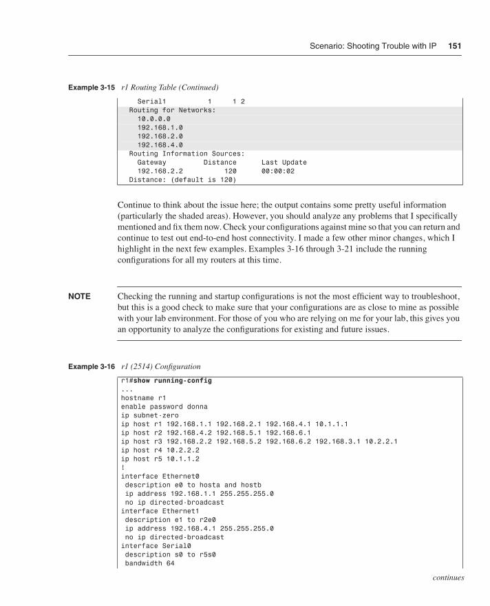
Continue to think about the issue here; the output contains some pretty useful information (particularly the shaded areas). However, you should analyze any problems that I specifically mentioned and fix them now. Check your configurations against mine so that you can return and continue to test out end-to-end host connectivity. I made a few other minor changes, which I highlight in the next few examples. Examples 3-16 through 3-21 include the running configurations for all my routers at this time.
NOTE Checking the running and startup configurations is not the most efficient way to troubleshoot, but this is a good check to make sure that your configurations are as close to mine as possible with your lab environment. For those of you who are relying on me for your lab, this gives you an opportunity to analyze the configurations for existing and future issues.
Serial1 1 1 2 Routing for Networks: 10.0.0.0 192.168.1.0 192.168.2.0 192.168.4.0 Routing Information Sources: Gateway Distance Last Update 192.168.2.2 120 00:00:02 Distance: (default is 120)
Example 3-16 r1 (2514) Configuration
r1#show running-config ...hostname r1enable password donnaip subnet-zeroip host r1 192.168.1.1 192.168.2.1 192.168.4.1 10.1.1.1ip host r2 192.168.4.2 192.168.5.1 192.168.6.1ip host r3 192.168.2.2 192.168.5.2 192.168.6.2 192.168.3.1 10.2.2.1ip host r4 10.2.2.2ip host r5 10.1.1.2!interface Ethernet0 description e0 to hosta and hostb ip address 192.168.1.1 255.255.255.0 no ip directed-broadcastinterface Ethernet1 description e1 to r2e0 ip address 192.168.4.1 255.255.255.0 no ip directed-broadcastinterface Serial0 description s0 to r5s0 bandwidth 64
Example 3-15 r1 Routing Table (Continued)
continues
057003i.fm Page 151 Tuesday, March 11, 2003 2:14 PM

152 Chapter 3: Shooting Trouble with IP
Next look at r2’s configuration in Example 3-17.
ip address 10.1.1.1 255.255.255.0 no ip directed-broadcast no ip mroute-cache no fair-queueinterface Serial1 description s1 to r3s0/0 bandwidth 64 ip address 192.168.2.1 255.255.255.0 no ip directed-broadcastrouter rip network 10.0.0.0 network 192.168.1.0 network 192.168.2.0 network 192.168.4.0ip classlessline con 0 logging synchronous transport input noneline aux 0line vty 0 4 password donna loginendr1#
Example 3-17 r2 (2501) Configuration
r2#show running-config ...hostname r2enable password donnaip subnet-zeroip host r1 192.168.1.1 192.168.2.1 192.168.4.1 10.1.1.1ip host r2 192.168.4.2 192.168.5.1 192.168.6.1ip host r3 192.168.2.2 192.168.5.2 192.168.6.2 192.168.3.1 10.2.2.1ip host r4 10.2.2.2ip host r5 10.1.1.2interface Ethernet0 description e0 to r1e1 ip address 192.168.4.2 255.255.255.0 no ip directed-broadcastinterface Serial0 description s0 to r3s0/1 bandwidth 64 ip address 192.168.6.1 255.255.255.0 no ip directed-broadcast no ip mroute-cache no fair-queueinterface Serial1 description s1 to r3s0/2 bandwidth 64 ip address 192.168.5.1 255.255.255.0
Example 3-16 r1 (2514) Configuration (Continued)
057003i.fm Page 152 Tuesday, March 11, 2003 2:14 PM

Scenario: Shooting Trouble with IP 153
Make any adjustments to your r2, and then analyze the r3 configuration in Example 3-18.
no ip directed-broadcastrouter rip network 192.168.4.0 network 192.168.5.0 network 192.168.6.0ip classlessline con 0 logging synchronous transport input noneline aux 0line vty 0 4 password donna loginendr2#
Example 3-18 r3 (3640) Configuration
r3#show running-config ...hostname r3enable password donnaip subnet-zeroip host r1 192.168.1.1 192.168.2.1 192.168.4.1 10.1.1.1ip host r2 192.168.4.2 192.168.5.1 192.168.6.1ip host r3 192.168.2.2 192.168.5.2 192.168.6.2 192.168.3.1 10.2.2.1ip host r4 10.2.2.2ip host r5 10.1.1.2interface Serial0/0 description s0/0 to r1s1 bandwidth 64 ip address 192.168.2.2 255.255.255.0 no ip directed-broadcast no ip mroute-cache clockrate 64000interface Serial0/1 description s0/1 to r2s0 bandwidth 64 ip address 192.168.6.2 255.255.255.0 no ip directed-broadcast clockrate 64000interface Serial0/2 description s0/2 to r2s1 bandwidth 64 ip address 192.168.5.2 255.255.255.0 no ip directed-broadcast clockrate 64000...interface FastEthernet2/0 description fa2/0 to hostc ip address 192.168.3.1 255.255.255.0 no ip directed-broadcast
Example 3-17 r2 (2501) Configuration
continues
057003i.fm Page 153 Tuesday, March 11, 2003 2:14 PM