P re su i co nta t d e c t b 0 x y 1 0
26
Pharmaceutical Engineering / Distillation 1 Sohansinh Vaghela/Pharmaceutical Engineering Saraswati Institute of Pharmaceutical Sciences, Gandhinagar Distillation Syllabus: Raoult’s law, phase diagrams, volatility, simple, steam and flash distillations, principles of rectification, Mc cabe Thiele method for calculations of number of theoretical plates, Azeotropic and extractive distillation. Definition Distillation may be defined as the separation of the constituents of a mixture including a liquid by partial vaporization of the mixture and separate and collect the vapor. Such separation may include (i) one liquid from non-volatile impurities. (ii) one liquid from one or more other liquids, with which it may be miscible, partially-miscible or immiscible N.B. In practice it is difficult to distinguish between evaporation, distillation and drying. Based on the intention: (i) when condensation vapor is required the operation is called distillation (ii) when the concentrated liquid residue is required the operation is called evaporation. (iii)when the dried solid residue is required as product the process is called drying BOILING POINT DIAGRAM OF A BINARY MIXTURE The figure represents the boiling point and equilibrium-composition relationship, at constant pressure. Two liquids A (b.p. t A ) and B (b.p. t B ) are taken in a chamber of constant pressure. Now at any temperature the vapor composition and liquid . a . c . b t t B t A 0 x y 100 d e Pressure is constant Mole % of component A Temperature
Transcript of P re su i co nta t d e c t b 0 x y 1 0

Pharmaceutical Engineering / Distillation 1
Sohansinh Vaghela/Pharmaceutical Engineering Saraswati Institute of Pharmaceutical Sciences, Gandhinagar
Distillation
Syllabus:
Raoult’s law, phase diagrams, volatility, simple, steam and flash distillations, principles of
rectification, Mc cabe Thiele method for calculations of number of theoretical plates, Azeotropic
and extractive distillation.
Definition
Distillation may be defined as the separation of the constituents of a mixture including a liquid by
partial vaporization of the mixture and separate and collect the vapor.
Such separation may include
(i) one liquid from non-volatile impurities.
(ii) one liquid from one or more other liquids, with which it may be miscible, partially-miscible or
immiscible
N.B.
In practice it is difficult to distinguish between evaporation, distillation and drying.
Based on the intention:
(i) when condensation vapor is required the operation is called distillation
(ii) when the concentrated liquid residue is required the operation is called evaporation.
(iii)when the dried solid residue is required as product the process is called drying
BOILING POINT DIAGRAM OF A BINARY MIXTURE
The figure represents the boiling point
and equilibrium-composition
relationship, at constant pressure.
Two liquids A (b.p. tA) and B (b.p. tB)
are taken in a chamber of constant
pressure. Now at any temperature the
vapor composition and liquid
.a
. c
. b
t
tB
tA
0 x y 100
d e
Pressure is constant
Mole % of component A
Temperature

Pharmaceutical Engineering / Distillation 2
Sohansinh Vaghela/Pharmaceutical Engineering Saraswati Institute of Pharmaceutical Sciences, Gandhinagar
composition will give two lines when plotted vs. temperature.
In boiling point diagram, temperatures are plotted as ordinates and compositions as abcissas.
The diagram consists of two curves, the ends of which coincide with the b.p. of two
components (tA and tB).
The upper-curve describes vapor composition and lower-curve liquid composition.
At any temperature, ‘t’ the horizontal line cuts the vapor composition curve at ‘e’ which
corresponds to vapor composition of y (mole%A) and cuts the liquid composition curve at ‘d’
which corresponds to liquid composition of x (mole% of A). So any two points on the same
horizontal line (such as d and e) represent compositions of liquid and vapor in equilibrium at
temperature ‘t’.
For all points above the top line (such as point ‘a’) the mixture is entirely vapor.
For all points below the bottom line (such as point ‘b’) the mixture is completely liquefied.
For all points between the two curves (such as point ‘c’) the system consists partly of liquid and
partly of vapor.
RAOULT’S LAW
Raoult’s law states that, at any particular temperature, the partial pressure of one component of a
binary mixture is equal to the mole fraction of that component multiplied by its vapor pressure in
the pure state at this temperature.
i..e Partial vapor pressure of a liquid (pA)
= vapor pressure of pure liquid( 0AP ) x mole fraction of the liquid(xA)
or, AAA xPp 0
e.g. to illustrate Raoult’s law, let us consider the case of benzene and toluene mixture.
At a temperature of 1000C toluene has a vapor pressure of 556 mm Hg. Consequently, if partial
pressure is plotted against composition, the partial pressures of toluene at various compositions will
fall along a straight line from 556 mm for pure toluene to zero for pure benzene. At this same
temperature benzene has vapor pressure of 1350 mm, and its
vapor pressure will change linearly from zero for 0%
benzene to 1350 mm for pure benzene.
The total pressure for any composition will be the sum of the
two partial pressures at that composition.

Pharmaceutical Engineering / Distillation 3
Sohansinh Vaghela/Pharmaceutical Engineering Saraswati Institute of Pharmaceutical Sciences, Gandhinagar
If the partial pressures are straight lines i.e. Raoult’s law holds then the total pressure will be a
straight line between 556 m for pure toluene and 1350 mm for pure benzene.
Ideal solution: Ideal solution is defined as a solution that obey’s Raoult’s law.
Examples: In these solutions the components have similar structures e.g. benzene and toluene
system, n-heptane and n-hexane, ethyl bromide and ethyl iodide etc.
In this case total pressure is equal to sum of the partial pressures of the components, i.e. P = (pA
+ pB )
The total pressure curve will be a straight line.
Non-ideal or real solutions
Solutions those will not obey Raoult’s law are known as non-ideal or real solutions.
Most real solutions shows deviation. The deviations are observed due to uneven solute-solute,
solute-solvent and / or solvent-solvent interactions. Two types of deviations are found:
(i) Positive deviation
In these systems the over all vapor pressure is greater than the sum of the partial vapor pressures of
the individual components, i.e. P > (pA + pB )
When the components differ in their polarity, length of carbon chain or degree of association, the
system may show positive deviation.
Examples: Carbontetrachloride and cyclohexane, benzene and ethanol.
(i) Negative deviation

Pharmaceutical Engineering / Distillation 4
Sohansinh Vaghela/Pharmaceutical Engineering Saraswati Institute of Pharmaceutical Sciences, Gandhinagar
In these systems the over all vapor pressure is lower than the sum of the partial vapor pressures of
the individual components, i.e. P < (pA + pB )
If hydrogen bonding, salt formation and hydration occurs then these systems may show negative
deviation.
Examples: Chloroform and acetone, pyridine and acetic acid, water and nitric acid.
VOLATILITY
The volatility of any substance in solution may be defined as the equilibrium partial pressure of the
substance in the vapor phase divided by the mole fraction of the substance in the solution.
A
AA
X
p
solutioninAoffractionMole
AofpressurevaporPartialvAcomponentofVolatility ,
Relative volatility
For a more volatile phase in equilibrium with a liquid phase, the relative volatility of component A
(the more volatile component) with respect to component B is defined by the equation:
AB
A A
B B
y x
y x
/
/
where
AB = relative volatility of component A with respect to
component B
y = mole fraction of component A in vapor phase
x = mole fraction of component in liquid phase
Relative volatility can also be expressed as
In case of binary system, yB = 1 – yA and xB = 1 –
xA.
Substituting,
AB
A
A
A
A
y
y
x
x
1
1
Rearranging we get AAB
AABA
X
XY
)1(1
XA
YA
YA
XA0 1.0
0
1.0
x
x
x
x
xx
xx
Equilibrium curve

Pharmaceutical Engineering / Distillation 5
Sohansinh Vaghela/Pharmaceutical Engineering Saraswati Institute of Pharmaceutical Sciences, Gandhinagar
From Dalton’s law
BA
A
pp
py
P
xPA
Therefore, P
P
x
y A
y = mole fraction of component A in vapor phase
x = mole fraction of component A in liquid phase
So relative volatility can also be expressed as
B
A
B
AAB
P
P
PP
PP
/
/
Equilibrium curve
If AB is given then from the above equation a set of XA and YA can be calculated. When YA is
plotted against XA the curve is called equilibrium curve.
Example
The vapor pressures of benzene and toluene are as given in the table. Assuming that mixtures of
benzene and toluene obey Raoult’s law, calculate and plot the boiling-point diagram for this pair of
liquids at 760mm total pressure.
Solution:
Let us take one temperature 1800F
So at 1800F, PA = 811 Hg
PB = 345 mm Hg
We have to calculate the mole fraction of benzene in liquid (x) and in vapor (y).
From the eqn.:
P = PAx + PB (1 – x)
or, 760 = 811 x + 345 (1 – x)
or, x = 0.891

Pharmaceutical Engineering / Distillation 6
Sohansinh Vaghela/Pharmaceutical Engineering Saraswati Institute of Pharmaceutical Sciences, Gandhinagar
From eqn. yP x
P
A 951.0760
891.0811
x
Similarly for all temperature values corresponding x
and y values may be calculated:
Temp Benzene
PA
Toluene
PB
x y
176.2 760 314 1.000 1.000
180 811 345 0.891 0.950
185 882 378 0.758 0.880
190 957 414 0.637 0.802
195 1037 452 0.526 0.718
200 1123 494 0.423 0.625
205 1214 538 0.328 0.525
210 1310 585 0.241 0.416
215 1412 635 0.161 0.299
220 1520 689 0.085 0.171
225 1625 747 0.015 0.032
230 1756 760 0.000 0.000
Example
Construct an equilibrium curve for binary system of benzene – toluene from the given data.
Data Boiling point at 1
atm
Vapor pressure of
benzene (PA)
Vapor pressure
of toluene (PB) B
AAB P
P
Benzene
Toluene
80.10C
110.60C
760 mm
1780 mm
270 mm
760 mm
2.81
2.34
Therefore, average relative volatility over the temperature range 80.1 to 110.60C
57.22
34.281.2)(
avgAB
Therefore, A
A
A
AA
X
X
X
XY
57.11
57.2
)157.2(1
57.2
XA 0.1 0.2 0.3 0.4 0.5 0.6 0.7 0.8 0.9
YA 0.222 0.391 0.524 0.631 0.720 0.794 0.857 0.911 0.959
Temperature
Boiling point diagram for benzene-toluene system at 1 atm pressure
Mole fraction of Benzene
1.00.50175
240

Pharmaceutical Engineering / Distillation 7
Sohansinh Vaghela/Pharmaceutical Engineering Saraswati Institute of Pharmaceutical Sciences, Gandhinagar
Equilibrium curve of benzene-toluene system
0
0.2
0.4
0.6
0.8
1
0 0.2 0.4 0.6 0.8 1
XA
YA

Pharmaceutical Engineering / Distillation 8
Sohansinh Vaghela/Pharmaceutical Engineering Saraswati Institute of Pharmaceutical Sciences, Gandhinagar
DISTILLATION METHODS
A. Distillation methods for miscible liquid systems
1. Simple Distillation
2. Flash Distillation / Equilibrium Distillation
3. Fractional Distillation / Rectification
4. Distillation under reduced pressure (e.g. Molecular Distillation)
5. Special Distillation Methods for non-ideal mixtures
(a) Distillation of Azeotropic Mixtures
(b) Extractive Distillation
B. Distillation of immiscible liquids (e.g. Steam Distillation)
SIMPLE / DIFFERENTIAL DISTILLATION
Simple distillation is a process in which a single component from a liquid
(or mixture) is converted into vapor, the vapor is transferred to another
place and recovered by condensing it.
In this process vapor is removed from the system as soon as it is formed
and condensed.
Use:
This method is commonly used in laboratory
In industries it is only used for systems having high relative volatilities.
Objective
Simple distillation is the process of converting a liquid into its vapors which, are passed through a
cooling surface to condense the vapors. The condensed vapors are reformed into liquid which, is
collected in a receiver.
Apparatus for laboratory scale
It consists of a distillation flask with a side arm sloping downward that is connected to a condenser.
The condensed vapors are collected in a flask called ‘receiver’. The whole apparatus is made of
glass.
A thermometer is fitted in the distillation flask to note down the temperature at which, the vapors
are distilled.
W x
dW y

Pharmaceutical Engineering / Distillation 9
Sohansinh Vaghela/Pharmaceutical Engineering Saraswati Institute of Pharmaceutical Sciences, Gandhinagar
Bumping is avoided by adding small pieces of porcelain or porous pot before distillation.
Large scale equipment for simple distillation
Construction
The still is made up of stainless steel, copper,
or any other suitable material. A thermometer
is fixed to the still to note the temperature of
the boiling liquid. An observation window in
the hood is helpful to the operator to see the
level of the boiling liquid. The still is
connected to a condenser and then to a
receiver. The bottom of the still is jacketed
through which steam is introduced to heat the
still.
Working
A liquid to be distilled is filled into the still to ½ to 2/3rd
of its volume. Bumping of the liquid is
avoided by placing few small pieces of porcelain or glasses before the distillation. Water is
circulated through the condenser.
Steam is passed through the inlet. The contents are heated gradually. The liquid begins to boil after
some time. The vapor begins to rise and passes into the condenser. The temperature rises very
quickly and reaches the boiling point of that liquid.
The vapor is condensed and collected into the receiver.
Sightglass
Condenser
Waterinlet
ReceiverSteam
Thermometer
Still
Fig. Simple distillation i n large scale

Pharmaceutical Engineering / Distillation 10
Sohansinh Vaghela/Pharmaceutical Engineering Saraswati Institute of Pharmaceutical Sciences, Gandhinagar
Apparatus for preparation of purified water
The boiler may be made of cast iron but the
baffles and the condenser tubes that comes
into contact with product are made of
stainless steel or monel metal.
The cold water from the water tap enters
the still through the inlet, which rises in the
jacket fitted with a constant level device,
the excess of water over flow through the
outlet.
A portion of hot water at 90 to 950C enters
into the boiler through a narrow opening –
the level of water is maintained in the
boiler up to overflow level.
The water is boiled in the boiler by means
of heating coils. On heating, the dissolved gases in the condenser are allowed to escape through
a small opening and only the steam escapes into the condensing tubes.
Since the dissolved gases are more volatile than water they escape in the first portion of the
distillate, therefore, must be rejected. Similarly, the last portion may contain volatile portion of
the dissolved solid substances in tap water – hence, discarded.
Application of simple distillation in pharmacy
1. It is used for the preparation of distilled water and water for injection.
2. Many volatile oils and aromatic waters are prepared by simple distillation e.g. Spirit of nitrous
ether and Aromatic Spirit of Ammonia
3. Concentration of liquid and to separate non-volatile solid from volatile liquids such as alcohol
and ether.
FLASH DISTILLATION /
EQUILIBRIUM
DISTILLATION
Heating coils
Escape forgases
Constant leveldevice
Distillate
Water
inlet
Wateroutlet
Fig. Distillation unit for purified water
Jacket
Liquid, x
Vapor to condenser, y
chamber
Heating
Steam
Feed
Pressure reducingvalve
Vaporseparator
Fig. Apparatus for flash distillation
Pharmaceutical Engineering / Distillation 11
Sohansinh Vaghela/Pharmaceutical Engineering Saraswati Institute of Pharmaceutical Sciences, Gandhinagar
PRODUCT
REFLUX
HEATRESIDUE
FEEDSTILL
SER
CONDEN
LIQUID
VAPOUR
Principle: When a hot mixture is allowed to enter from a high-pressure zone into a low pressure
zone, the entire liquid mixture is suddenly vaporized. This process is known as flash vaporization.
During this process, the chamber is cooled. The less volatile fraction is condensed and the more
volatile component remains in the vapor phase. This process requires time, hence liquid and vapor
are kept in intimate contact until equilibrium is achieved.
Flash distillation is also called equilibrium distillation because separation of two liquids takes place
when liquid and vapor phases are at equilibrium.
Construction: It consists of a pump, which is connected to a feed reservoir. Pumps help in
pumping the feed into the heating chamber. The heating chamber is heat is supplied by steam. The
other end of the pipe is directly introduced into the vapor-liquid separator through a reducing valve.
The vapor outlet is provided at the top of the separator and liquid outlet is provided at the bottom.
Working: The feed is pumped through a heater at a certain pressure. The temperature of the liquid
is raised in the heating chamber but the liquid does not boil under high pressure (because boiling
point increases). When the liquid enters into the vapor-liquid separator, due to drop in pressure, the
liquid reaches the boiling point under that reduced pressure and the liquid suddenly boils. The
vapor flashes out from the hot liquid. Since the vapor takes the latent heat the liquid gets cooled
down. The less volatile component of the vapor is condensed and more volatile component remains
in the vapor phase. The mixture is allowed for sufficient time so that vapor and liquid comes at
equilibrium. The vapor is separated through an outlet provided at the top and the liquid is collected
at the bottom.
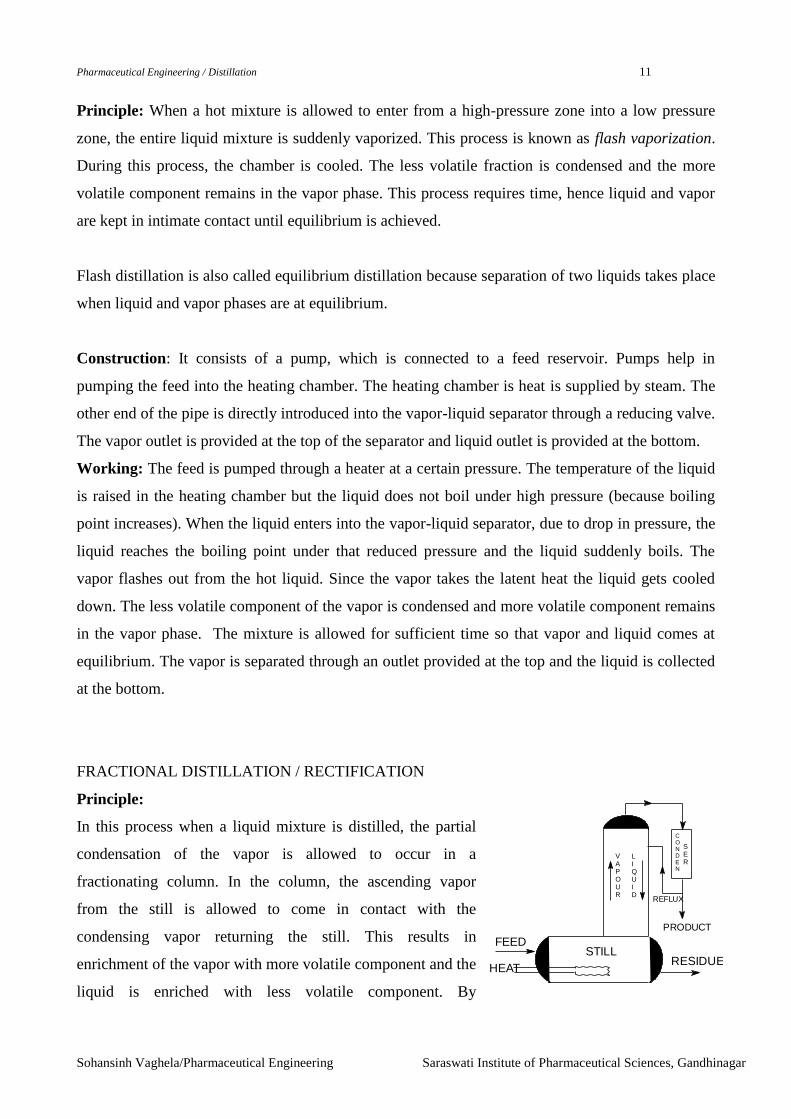
FRACTIONAL DISTILLATION / RECTIFICATION
Principle:
In this process when a liquid mixture is distilled, the partial
condensation of the vapor is allowed to occur in a
fractionating column. In the column, the ascending vapor
from the still is allowed to come in contact with the
condensing vapor returning the still. This results in
enrichment of the vapor with more volatile component and the
liquid is enriched with less volatile component. By

Pharmaceutical Engineering / Distillation 12
Sohansinh Vaghela/Pharmaceutical Engineering Saraswati Institute of Pharmaceutical Sciences, Gandhinagar
condensing the vapor and reheating the liquid repeatedly, equilibrium between liquid and vapor is
set up at each stage, which ultimately results in the separation of a more volatile component.
A rectifying unit consists primarily of
(a) a still or reboiler, in which vapor is generated,
(b) a rectifying or fractionating column through which this vapor rises in counter-current contact
with a descending stream of liquid, and
(c) a condenser, which condenses all the vapor leaving the top of the column, sending part of this
condensed liquid (the reflux) back to the column to descend counter to the rising vapors, and
delivering the rest of the condensed liquid as product.
As the liquid stream descends the column, it is progressively enriched with the less volatile
constituent.
The top of the column is cooler than the bottom, so that the liquid stream becomes
progressively hotter as it descends and the vapor stream becomes progressively cooler as it rises.
This heat transfer is accomplished by actual contact of liquid and vapor, and for this purpose
effective contact is desirable.
CONSTRUCTION OF RECTIFYING COLUMN
There are different varieties of equipments for rectification
(a) Plate column (i) Bubble cap column (ii) Sieve-plate column
(b) Packed column

Pharmaceutical Engineering / Distillation 13
Sohansinh Vaghela/Pharmaceutical Engineering Saraswati Institute of Pharmaceutical Sciences, Gandhinagar
BUBBLE-CAP COLUMN
The column is divided into sections by means of a series of horizontal plates A.
Each plate carries a number of short nipples B (or riser). Each nipple is covered by a bell-
shaped cap C that is secured by a spider and bolt with the plate. The edge of the cap is serrated
or the sides may be slotted.
Vapor rises from the plate below through the nipple, is diverted downward by the cap, and
bubbles out under the serration or through the slots.
A layer of liquid is maintained on the plate by means of an overflow or down-pipe (F) and the
depth of the liquid is such that the slots are submerged.
The down-pipe, (G) from the plate above, is sealed by the liquid on the plate below, so that the
vapor cannot enter the down-pipe.
Ordinarily, the liquid is delivered at one end of a diameter by the down-pipe from the plate
above, flows the other end of the same diameter.
STILL
FEEDVapour
Reflux
Liquid
Rectification
column
Vapour
Bubble cap
Plate(A)
Plate (A)
Nipple (B)
Cap (C)
(C)
Layer ofLiquid
Down pipe(F)
Vapour
Down pipe(F)
Down pipe(G)
Slot

Pharmaceutical Engineering / Distillation 14
Sohansinh Vaghela/Pharmaceutical Engineering Saraswati Institute of Pharmaceutical Sciences, Gandhinagar
Types of down-comers
(a) Cross flow
The liquid flows across the plate from right to left on plate F and left to right on plate H and so on
down the column.
(b) Split flow
On plate F the liquid flows form the two sides to the center. On plate H it flows from the center to
the two sides and so on down the column. This arrangement is commonly known as split flow.
(c) Reverse flow
Liquid comes down the space on one side of the baffle and flows across the plate from right to left,
around the end of the baffle, from left to right and down the space behind the weir. This
arrangement is called reverse flow.
(d) Radial flow with circular down-take
One plate will have four or more down-comers around the circumference, and the next plate will
have a down-comer at the center so that on the upper plate the flow is from the circumference
towards center and on the next plate the flow is from the central down-take to the circumference.
Specification of bubble cap rectification column
Column diameter 2 to 15 ft
Height few feet to over 100 ft
Bubble cap diameter 3 to 6 inches
Cross flow
F
F
G
G
F
G
F
G
Split flow
Baffle
F
G
F
G
Reverse Flow Radial Flow

Pharmaceutical Engineering / Distillation 15
Sohansinh Vaghela/Pharmaceutical Engineering Saraswati Institute of Pharmaceutical Sciences, Gandhinagar
Slots in a 3 inches bubble cap may be 1/8 to 3/32 inch wide
½ to 1 inch height

Pharmaceutical Engineering / Distillation 16
Sohansinh Vaghela/Pharmaceutical Engineering Saraswati Institute of Pharmaceutical Sciences, Gandhinagar
SIEVE PALTE COLUMNS
All the constructions are same as bubble cap columns. Instead of bubble cap plates, flat plates with
a large number of relatively small perforations, drilled in them are used. These perforations are
usually 3/16 to ¼ inch in diameter.
The velocity of the vapor through these holes is sufficient to produce the liquid running down the
holes.
PACKED COLUMNS
The column is entirely filled with some sorts of material that offers a large surface area supposedly
wetted by the liquid.
A large variety of materials are used among which Raschig rings are popular. A Raschig ring is a
hollow cylinder whose length is equal to its diameter. This may be made of metal (by sawing
sections off a pipe), stone ware, ceramics, carbon, plastics, or other materials. Raschig rings are
usually dumped at random in the column.
Raschig Ring Lessing Ring Pall Ring Berl Saddle Intalox Saddle
Advantages
(i) Have a low pressure drop per unit of height than bubble cap
(ii) For very small diameters of column, where it would be difficult to get in more than two or
three bubble caps, a packed column can be used.
(iii) Since Raschig rings can be made of any material, hence packed columns can be used for
corrosive materials.
(iv) The amount of liquid held up in the column is low so thermolabile liquid remains in contact
with high temperature for a short time than bubble cap method.
Disadvantages
(i) They are relatively inflexible.
(ii) Distribution of liquid uniformly in such packed column is difficult. It is found that, as the
liquid passes down the tower it tends to concentrate at the walls and leave the center dry.

Pharmaceutical Engineering / Distillation 17
Sohansinh Vaghela/Pharmaceutical Engineering Saraswati Institute of Pharmaceutical Sciences, Gandhinagar
V
Condenser
Reboiler
OverheadproductD, xD
RefluxL, xa
VaporVa, ya
BottomProductB, xB
FeedF, xF
yb
Lb
xb
McCABE – THIEL METHOD OF CALCULATION OF NUMBER OF PLATES
The feed contains two miscible components A and B. A is more volatile and B is less volatile
component. The feed is entered on a plate in the central position of the column. This plate is called
feed plate. The liquid film flows down the column. Vapor rises from the boiler at the bottom of the
column.
Rectification unit: At the plates above the feed plate forms the rectification unit. At these plates the
reflux liquid is flowing down. Ideally it should be free of component A. But small amount of A
remains. This small amount of A is also taken out by the vapor. Hence this unit is called
rectification unit (some kinds of mistake is rectified).
Stripping unit: In the feed plate and the lower plates the feed liquid (full of component A) flows
downward. On the way it passes through the vapor that extracts the component A, hence it is called
stripping section.
Material Balances in Plates
All the component flow rate is expressed in
moles and the concentration in mole fraction.
Step-I : Over all material balance
Overall material balance:
Total material balance: F = D + B
Component A balance: FxF = DxD + BxB.
Eliminating B we get: BD
BF
xx
xx
F
D
Eliminating D we get: BD
FD
xx
xx
F
B
N.B. Why we are expressing in F
D and F
B format?
Because the D and B are expressed in terms of fraction
of F (i.e. Feed flow rate).
Step-II Net flow rate in rectification section
Condenser
Va
ya
DxD
La
xa
Ln
xn
Vn+1
yn+1
Rectifying section

Pharmaceutical Engineering / Distillation 18
Sohansinh Vaghela/Pharmaceutical Engineering Saraswati Institute of Pharmaceutical Sciences, Gandhinagar
* Material balance around condenser:
Material entering condenser = Material leaving condenser
or, DLV aa or, aa LVD
* Material balance around upper section:
Material entering upper section = Material leaving upper section
La + Vn+1 = Ln + Va or, Vn+1 – Ln = Va – La = D.
And Vn+1 = D + Ln.
* Material balance with respect to component A
Vn+1 yn+1 – Ln xn = DxD.
or, Dnnnn DxxLyV 11
or, 11
1
n
Dn
n
n
nV
Dxx
V
Ly
For convenience Vn+1 is exchanged with Ln + D
DL
Dxx
DL
Ly
n
Dn
n
n
n
1 This equation is operating line-1 for rectifying section.
Step-III Net flow rate in stripping section
* Material balance around reboiler
Material entering the reboiler = material leaving the reboiler
or, Lb = Vb + B or, B = Lb – Vb.
* Material balance around lower section
Material entering the lower section = Material leaving the
lower section
1 mbbm VLVL
or, BVLVL bbmm 1
or, 11 mmmmB yVxLBx
or, Bmmmm BxxLyV 11
or, 11
1
m
Bm
m
m
mV
Bxx
V
Ly
Vb
yb
Lm
xm
Vm+1
ym+1
Reboiler
Lb
xb
BxB

Pharmaceutical Engineering / Distillation 19
Sohansinh Vaghela/Pharmaceutical Engineering Saraswati Institute of Pharmaceutical Sciences, Gandhinagar
or, BL
Bxx
BL
Ly
m
Bm
m
m
m
1 Operating line-2 for rectifying section
Operating line-1 and operating line-2 shows that if Ln Lm then the operating lines will be curved
and become difficult to draw unless the xn, xm, yn and ym of all the internal plates are known.
Assumption: Constant molal overflow
In order to simplify the equations for operating lines it is assumed that
The heat required to vaporize one mole of component A is nearly equal to the heat required to
condense one mole of component B. In this case the enthalpy of component A and B is not required
and the operating lines become linear.
Subscripts n, n+1, n–1 m, m+1 and n–1, L and V may be ignored and the simplified equations
thus obtained are as follows:
Operating line-1: DL
Dxx
DL
Ly
n
Dn
n
n
n
1
DL
Dxx
DL
Ly D
Operating line-2: BL
Bxx
BL
Ly
m
Bm
m
m
m
1 BL
Bxx
BL
Ly B
Now let us put x = xD in operating line 1
We get DL
Dxx
DL
Ly D
D
Or, Dx
DL
DLy
Or, Dxy
Similarly if we put Bxx in operating line-2
then Bxy
x and y will be same at any point on diagonal. Thus, operating line-1 and 2 are cutting the diagonal
at xD and xB respectively.
Feed plate
At the feed plate the liquid flow rate or the vapor flow rate or both may be changed depending on
the thermal condition of the feed. All conditions of feed flow can be expressed by a term q, which
y
x
Operating line-1
Operating line-2
xD
xB

Pharmaceutical Engineering / Distillation 20
Sohansinh Vaghela/Pharmaceutical Engineering Saraswati Institute of Pharmaceutical Sciences, Gandhinagar
is defined as the moles of liquid flow in the stripping section that result from the introduction of
each mole of feed. i.e.
F
LL
FeedofMoles
platethebelowreachedfeedtheofMolesq
Case-1: Feed is cold liquid:
In this case the some amount of vapor condenses and add
to the liquid flowing down. Here F
VCondensedFq
So q > 1
Case-2: Feed is boiling liquid:
In this case the feed liquid remains unchanged i.e no vaporization of feed nor
any condensation of vapor.
Here 1F
Fq So q = 1
Case-3: Feed partially vaporized
In this case vapor part of the feed rise above with the vapor.
Here F
portionVaporFq
So, 0 < q < 1
Case-4: Feed is vapor at dew point (i.e. saturated vapor)
In this case the total feed goes into vapor phase.
Here 0
F
FFq So, q = 0
Case-5: Feed is super heated vapor
In this case the total feed goes into vapor phase and it vaporizes some amount of the reflux liquid
also.
Here 0
F
liquidrefluxofamountsomevaporizeFFq So, q < 0
Feed line
Assumption: q fraction of feed is converted to liquid and (1 – q) fraction is
vaporized.
* Material balance in the feed plate:
qFLL Therefore, qFLL
FqVV )1( Therefore, FqVV )1(
L
L V
V
F
L
L V
V
F
L
L V
V
F
L
L V
V
F
F
L
Feed plate
L V
V

Pharmaceutical Engineering / Distillation 21
Sohansinh Vaghela/Pharmaceutical Engineering Saraswati Institute of Pharmaceutical Sciences, Gandhinagar
Operating line on the feed plate
Operating line-1: DL
Dxx
DL
Ly D
or,
V
Dxx
V
Ly D or,
DDxxLVy eqn-1
Operating line just below the feed plate
Operating Line-2: BL
Bxx
BL
Ly B
or,
V
Bxx
V
Ly B or,
BBxxLyV eqn-2
Eqn-1 – Eqn-2: )()()( BD xBDxxLLVVy
Or, FFxxqFFyq )1( [Since FxF = DxD + BxB]
Or, q
xx
q
qy F
11 ---------FEED LINE
If X = XF then from the feed line it is obtained Y = XF.
The position of feed line depends only on XF and q. The slope of the feed line is )1( q
q
.
Construction of operating lines
Operating line-1: DL
Dxx
DL
Ly D
describes the equation in the rectifying section
Operating line-2: BL
Bxx
BL
Ly B
describes the equation in the stripping section
Operating line-3: q
Fx
xq
qy
11 describes feed line
Where y = mole fraction of more volatile component (A) in the vapor phase
x = mole fraction of more volatile component (A) in the liquid phase
L = moles of liquid on nth
plate
V = moles of liquid leaving the nth
plate.
D = moles of overhead product leaving the system
B = moles of bottom product leaving the system
y
x
y
Feed line
xF
Slope = --
q
1 - q

Pharmaceutical Engineering / Distillation 22
Sohansinh Vaghela/Pharmaceutical Engineering Saraswati Institute of Pharmaceutical Sciences, Gandhinagar

Pharmaceutical Engineering / Distillation 23
Sohansinh Vaghela/Pharmaceutical Engineering Saraswati Institute of Pharmaceutical Sciences, Gandhinagar
Step-5:
From XD a horizontal line is drawn up to the equilibrium
curve. From the point of intersection a vertical is drawn
up to the first operating line. The triangular area enclosed
is depicting the topmost plate.
Similarly from the intersection of first plate a horizontal
line is drawn towards the equilibrium curve. From the
intersection point a vertical line is drawn to construct the
2nd
plate. Like wise one after another plates are drawn
DxD
L + D
y
Operating line-1
xD
Feed line
xD
xF
Step-3: Operating line-1 is drawn by joining the
intersection point of xD and diagonal line (i.e. x =xD)
and the intercept DxD / (L + D)
DxD
L + D
y
x
Operating line-1
Operating line-2
xD
xB
Feed line
Step-4: Operating line-2 is drawn from the intersection
point of XB and the intersection point of feed line and
operating line-1.
y
x
xD
xB
1
2
3
4
5
6
7
Feed plate

Pharmaceutical Engineering / Distillation 24
Sohansinh Vaghela/Pharmaceutical Engineering Saraswati Institute of Pharmaceutical Sciences, Gandhinagar
and when the vertical line crosses the feed line the line is drawn up to second operating line. Again
the plates are drawn up to point XB.
The total number of triangles are counted. In this figure the total number of theoretical plates is 7
and the position of feed plate is 4th
.
INDUSTRIAL SCALE DISTILLATION OF AZEOTROPIC MIXTURE
The liquor from fermentation process is a common source of ethanol and contains approximately
8–10% ethanol.
After simple distillation an azeotrope will form containing 95.6% (96E+4W) ethanol and boiling at
78.150C at atmospheric pressure.
In this type of system a reboiler is used instead of boiler. The feed liquor is introduced into the
system and must occur at a point where the equilibrium will not be disturbed. Hence, feed will take
place, at a place part of the way up the column, where the equilibrium composition on the plate is
similar to the feed composition.
The plate below the feed plate form the stripping section where the rising vapor strips the more
volatile component (ethanol) from the feed liquor while the upper section is known as the rectifying
section.
The binary azeotrope produced at this stage is freed from water by making use of ternary azeotrope
– ethanol, benzene, and water.
The ethanol/water azeotrope, with sufficient benzene (only required at start-up) is fed to column A
and the pure ethanol is obtained as bottom product, since the ternary azeotrope takes off the water.

Pharmaceutical Engineering / Distillation 25
Sohansinh Vaghela/Pharmaceutical Engineering Saraswati Institute of Pharmaceutical Sciences, Gandhinagar
The azeotrope (E+B+W) is taken from the top of the column A, condensed and separated (in
liquid-liquid separator) into two layers, having the compositions given in the diagram.
The upper layer predominates and, being rich in benzene (14.5E+1.0W+84.5B), is returned to
column A. The lower layer (53E+36W+11B) is taken to column B, where the benzene is
recovered as the ethanol/benzene binary azeotrope (67E+33B) and is mixed with the vapor
from ethanol.
The ethanol / water residue passes to column C, where the ethanol is recovered as the
ethanol/water binary azeotrope (96E+4W), which can be incorporated with the original feed.
The final product from column A is 100% ethanol and from column C is 100% water.
EXTRACTIVE DISTILLATION
Extractive distillation is same as azeotropic distillation except that the third agent that is added is
relatively non-volatile liquid compared to the components to be separated.
e.g. (i) separation of toluene from iso-octane – the third agent is phenol.
(ii) separation of butadiene from a mixture of butane and butene – the third agent is furfural.
Feed 96E + B
18.5E
7.4W
74.1B
14.5E
1.0W
84.5B
84 Vol
16 Vol
53E
36W
11B
67E + 33B
E + B
100 W100 E
96E + 4W
96E
4W
E = ethanolW = waterB = benzene
Fig. Plant for manufacture of Absolute ethanol (100% ethanol)
A B C
Liq-liq
separator

Pharmaceutical Engineering / Distillation 26
Sohansinh Vaghela/Pharmaceutical Engineering Saraswati Institute of Pharmaceutical Sciences, Gandhinagar