P. MACHIBRODA ENGINEERING LTD. GEOTECHNICAL …€¦ · The Terms of Reference were presented in P....
31
P. MACHIBRODA ENGINEERING LTD. CONSULTING GEOTECHNICAL GEOENVIRONMENTAL ENGINEERS AND GEOSCIENTISTS SASKATOON 806 – 48 TH STREET EAST SASKATOON, SK S7K 3Y4 PHONE: (306) 665-8444 FAX: (306) 652-2092 E-MAIL: [email protected] WEB: www.machibroda.com • Geotechnical Engineering • Foundation Design Recommendations • Inspection Services • Earthwork Structures • Slope Stability • Pavement Design • Hydrogeological Studies • Environmental Site Assessments • Site Decommissioning and Clean-up • Test Drilling Services • Piezocone (CPTu) Testing • Soils Testing • Concrete Testing • Asphalt Testing Member of the Association of Consulting Engineering Companies / Canada 12114A 163 STREET N. W. • EDMONTON, AB • PHONE: (780) 733-6575 GEOTECHNICAL INVESTIGATION PROPOSED DAIRY QUEEN 703 100 TH STREET EAST TISDALE, SASKATCHEWAN PMEL FILE NO. S14-8761 MAY 16, 2016 PREPARED FOR: PRAKASH CONSULTING LTD. #4, 210 – 15 TH STREET EAST PRINCE ALBERT, SASKATCHEWAN S6V 1G2 ATTENTION: MR. MARTIN KIFFIAK, P.ENG.
Transcript of P. MACHIBRODA ENGINEERING LTD. GEOTECHNICAL …€¦ · The Terms of Reference were presented in P....

P. MACHIBRODA ENGINEERING LTD. CONSULTING GEOTECHNICAL GEOENVIRONMENTAL ENGINEERS AND GEOSCIENTISTS SASKATOON 806 – 48TH STREET EAST SASKATOON, SK S7K 3Y4 PHONE: (306) 665-8444 FAX: (306) 652-2092
E-MAIL: [email protected] WEB: www.machibroda.com
• Geotechnical Engineering
• Foundation Design
Recommendations
• Inspection Services
• Earthwork Structures
• Slope Stability
• Pavement Design
• Hydrogeological Studies
• Environmental Site
Assessments
• Site Decommissioning and
Clean-up
• Test Drilling Services
• Piezocone (CPTu) Testing
• Soils Testing
• Concrete Testing
• Asphalt Testing
Member of the Association of Consulting
Engineering Companies / Canada 12114A 163 STREET N. W. • EDMONTON, AB • PHONE: (780) 733-6575
GEOTECHNICAL INVESTIGATION PROPOSED DAIRY QUEEN
703 100TH STREET EAST TISDALE, SASKATCHEWAN
PMEL FILE NO. S14-8761 MAY 16, 2016
PREPARED FOR:
PRAKASH CONSULTING LTD. #4, 210 – 15TH STREET EAST
PRINCE ALBERT, SASKATCHEWAN S6V 1G2
ATTENTION: MR. MARTIN KIFFIAK, P.ENG.
PMEL File No. S14-8761 May 16, 2014 Page i
TABLE OF CONTENTS
Page 1.0 INTRODUCTION ................................................................................................... 1
2.0 FIELD INVESTIGATION ....................................................................................... 1
3.0 FIELD DRILL LOGS ............................................................................................. 2
3.1 Soil Profile .......................................................................................................... 2
3.2 Groundwater Conditions, Sloughing ................................................................... 2
3.3 Cobblestones and Boulders ............................................................................... 3
4.0 LABORATORY ANALYSIS .................................................................................. 3
5.0 DESIGN RECOMMENDATIONS .......................................................................... 3
5.1 Design Considerations ....................................................................................... 4
5.2 Site Preparation ................................................................................................. 5
5.3 Helical Screw Piles ............................................................................................. 6
5.4 Drilled, Cast-in-Place Concrete Piles and/or Belled Caissons............................ 8
5.5 Limit States/Resistance Factors and Serviceability .......................................... 10
5.6 Floor System .................................................................................................... 11
5.6.1 Structural Floor with Void Filler ..................................................................... 11
5.6.2 Exterior Slabs/Sidewalks ............................................................................... 12
5.7 Grade Beams ................................................................................................... 12
5.8 Site Classification for Seismic Site Response .................................................. 12
5.9 Foundation Concrete ........................................................................................ 12
5.10 Asphalt Concrete Pavement Structures ........................................................... 13
6.0 LIMITATIONS ..................................................................................................... 15
P. MACHIBRODA ENGINEERING LTD.

PMEL File No. S14-8761 May 16, 2014 Page ii
LIST OF TABLES
Table I Skin Friction Bearing Pressures (Screw Piles)
Table II End Bearing Pressures (Screw Piles)
Table III Skin Friction Bearing Pressures (Drilled Piles)
Table IV End Bearing Pressure (Belled Caissons)
Table V Thickness Design for Pavement Structures
Table VI Aggregate Gradation Requirements
LIST OF DRAWINGS
S14-8761-1 Site Plan – Test Hole Locations
S14-8761-2 Field Drill Log and Soil Test Results
S14-8761-3 Field Drill Log and Soil Test Results
S14-8761-4 Field Drill Log and Soil Test Results
S14-8761-5 Field Drill Log and Soil Test Results
LIST OF APPENDICES
Appendix A Explanation of Terms on Test Hole Logs
Appendix B Topsoil, Organic Matter and Organics
P. MACHIBRODA ENGINEERING LTD.

PMEL File No. S14-8761 May 16, 2014 Page 1
1.0 INTRODUCTION
The following report has been prepared on the subsurface soil conditions existing at
the site of the proposed Dairy Queen to be constructed at 703 – 100th Street East,
in Tisdale, Saskatchewan.
Authorization to proceed with this investigation was provided on April 11, 2014.
The Terms of Reference were presented in P. Machibroda Engineering Ltd. (PMEL)
Proposal No. 0304-8507, dated March 5, 2013
The field test drilling and soil sampling were conducted on April 24 and May 5, 2014.
2.0 FIELD INVESTIGATION
Four test holes, located as shown on the Site Plan, Drawing No. S14-8761-1, were dry
drilled using our truck-mounted continuous flight, solid stem auger drill rig. The test
holes were 150 mm in diameter and extended to depths of 2.0 to 12.0 metres below the
existing ground surface.
Test hole drill logs were compiled during test drilling to record the soil stratification, the
groundwater conditions, the position of unstable sloughing soils and the depths at which
cobblestones and/or boulders were encountered.
Disturbed samples of auger cuttings were collected during test drilling and sealed in plastic
bags to minimize moisture loss. The soil samples were taken to our laboratory for
analysis.
Standard penetration tests (N-index), utilizing a safety hammer with automatic trip, were
performed during test drilling.
P. MACHIBRODA ENGINEERING LTD.

PMEL File No. S14-8761 May 16, 2014 Page 2
3.0 FIELD DRILL LOGS
The field drill logs recorded during test drilling are shown plotted on Drawing Nos.
S14-8761-2 to 5, inclusive.
The ground surface elevation at each Test Hole location was referenced to the top rim
of the manhole on HWY 35 located directly south west of the subject site as shown on
the Site Plan, Drawing No. S14-8761-1. A datum elevation of 100.000 metres was
assumed for the top of the manhole rim.
3.1 Soil Profile
The general soil profile consisted of asphalt concrete (30 to 50 mm thick) overlying
gravel and clay fill (extending to a depth of about 0.5 to 0.7 metres) followed by highly
plastic clay (extending to a depth of about 2.3 to 3.1 metres) then glacial till, which
extended to a depth of at least 12.0 metres, the maximum depth penetrated with our
Test Holes at this site.
Cinders were encountered within the clay fill in Test Hole No. 14-3.
3.2 Groundwater Conditions, Sloughing
Groundwater seepage and sloughing conditions were encountered during test drilling.
The depths at which groundwater seepage and sloughing conditions were encountered
are shown on Drawing Nos. S14-8761-2 to 5, inclusive. Based on the depths at which
groundwater seepage was encountered, the groundwater table at this site is anticipated
to be situated approximately 11.3 metres below existing ground surface. Higher or
perched groundwater levels should be expected during or following spring thaw or
periods of precipitation.
P. MACHIBRODA ENGINEERING LTD.

PMEL File No. S14-8761 May 16, 2014 Page 3
3.3 Cobblestones and Boulders
Cobblestones and/or boulders were encountered during test drilling. The depths at
which cobblestones and/or boulders were encountered are shown on Drawing Nos.
S14-8761-2 to 5, inclusive.
The glacial till consisted of a heterogeneous mixture of gravel, sand, silt and clay-sized
particles. The glacial till strata also contained sorted deposits of the above particle
sizes. In addition to the sorted deposits, a random distribution of larger particle sizes in
the cobblestone range (60 to 200 mm) and boulder-sized range (larger than 200 mm)
were encountered during test drilling.
It should be recognized that the statistical probability of encountering cobblestones
and/or boulders in the four small diameter Test Holes drilled at this large site was low.
Intertill deposits of cobblestones, boulders, boulder pavements and isolated deposits of
saturated sand or gravel should be anticipated. The frequency of encountering such
deposits will increase proportionately with the number of piles installed.
4.0 LABORATORY ANALYSIS
The soil classification and index tests performed during this investigation consisted of a
visual classification of the soil, water contents, Atterberg Limits and grain size distribution
analysis (P200).
The results of the soil classification and index tests conducted on representative samples
of soil have been plotted on the drill logs alongside the corresponding depths at which the
samples were recovered, as shown on Drawing Nos. S14-8761-2 to 5, inclusive.
5.0 DESIGN RECOMMENDATIONS Based on the foregoing outline of the soil test results, the following foundation
considerations and design recommendations have been presented.
P. MACHIBRODA ENGINEERING LTD.

PMEL File No. S14-8761 May 16, 2014 Page 4
5.1 Design Considerations
It is understood that the proposed Dairy Queen Building will encompass a plan area of
approximately 241 square metres (2,600 square feet) with adjacent asphalt concrete
parking. It is also understood a structural floor slab may be constructed.
The subsurface soil conditions consisted of asphalt concrete overlying gravel fill
followed by clay then glacial till. Based on the depths at which groundwater seepage
was encountered, the groundwater table at this site is anticipated to be situated
approximately 11.3 metres below existing ground surface. Higher groundwater levels
should be expected during or following spring thaw or periods of precipitation. The
subgrade soils are considered frost susceptible and the average depth of frost
penetration for a heated building in the Tisdale, Saskatchewan area is about 2 metres.
A deep foundation system consisting of helical screw piles or drilled, cast-in-place
concrete piles and/or belled caissons should perform satisfactorily as a foundation
support at the subject site. Construction difficulties associated with
cobblestone/boulders, groundwater seepage and sloughing conditions should be
expected during installation of drilled piles. Casing will be required to in some pile
holes.
Footings bearing on the high plastic clay will undergo differential movement due to
volume changes associated with moisture fluctuations within the soil profile. As such,
footings are not recommended at this site. It is understood that the existing building on
site has a basement. The basement is to be demolished and fill is to be placed in the
resulting excavation.
A grade supported floor slab within the new Building could be based on fill and/or highly
plastic clay. Due to the potential for differential movement associated with moisture
fluctuations in the soil profile and settlement of the newly placed fill, it is recommended
that a structural floor be constructed within the new Building.
P. MACHIBRODA ENGINEERING LTD.

PMEL File No. S14-8761 May 16, 2014 Page 5
Recommendations have been prepared for site preparation; helical screw piles; drilled,
cast-in-place concrete piles; limit states/resistance factors and serviceability;
floor systems; grade beams; foundation concrete; site classification for seismic
response; foundation concrete and asphalt concrete pavement structures.
5.2 Site Preparation
It is understood that an existing building located on the site will be demolished. All
demolition debris (including concrete slabs, foundations, etc.) should be removed from
the site prior to construction. In addition to the demolition debris, all organics, loose fill
and deleterious materials should be removed from the construction area.
The surface of the subgrade should be leveled and compacted to the following minimum
density requirements.
Building Areas - 96 percent of standard Proctor density at optimum moisture content;
Roadway Areas - 96 percent of standard Proctor density at optimum moisture content;
Landscape Areas - 90 percent of standard Proctor density at optimum moisture content
Subgrade fill, if required, should consist of granular material or non-expansive
(i.e., low-plastic), fine-grained soils. The fill should be placed in thin lifts (maximum
150 mm loose) and compacted to 96 percent of standard Proctor density at optimum
moisture content. All proposed subgrade fill should be approved by the Geotechnical
Consultant prior to placement.
The site should be graded to ensure positive site drainage away from the proposed
Building.
P. MACHIBRODA ENGINEERING LTD.
PMEL File No. S14-8761 May 16, 2014 Page 6
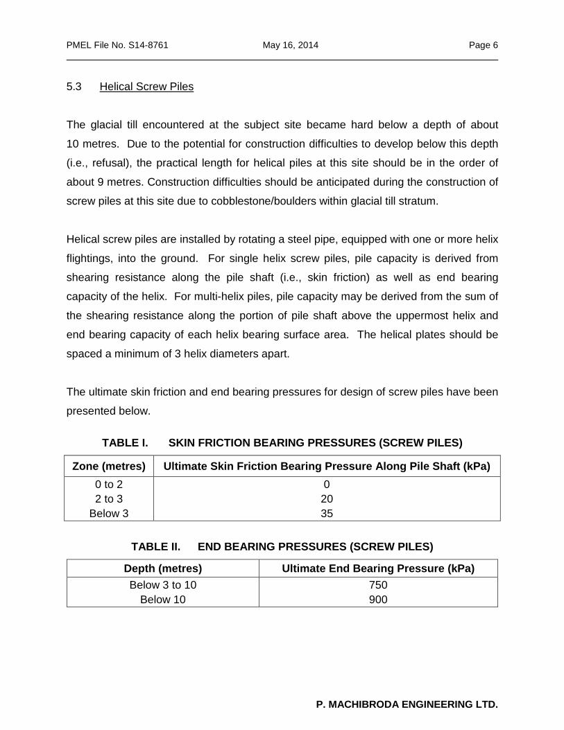
5.3 Helical Screw Piles
The glacial till encountered at the subject site became hard below a depth of about
10 metres. Due to the potential for construction difficulties to develop below this depth
(i.e., refusal), the practical length for helical piles at this site should be in the order of
about 9 metres. Construction difficulties should be anticipated during the construction of
screw piles at this site due to cobblestone/boulders within glacial till stratum.
Helical screw piles are installed by rotating a steel pipe, equipped with one or more helix
flightings, into the ground. For single helix screw piles, pile capacity is derived from
shearing resistance along the pile shaft (i.e., skin friction) as well as end bearing
capacity of the helix. For multi-helix piles, pile capacity may be derived from the sum of
the shearing resistance along the portion of pile shaft above the uppermost helix and
end bearing capacity of each helix bearing surface area. The helical plates should be
spaced a minimum of 3 helix diameters apart.
The ultimate skin friction and end bearing pressures for design of screw piles have been
presented below.
TABLE I. SKIN FRICTION BEARING PRESSURES (SCREW PILES)
Zone (metres) Ultimate Skin Friction Bearing Pressure Along Pile Shaft (kPa) 0 to 2 2 to 3
Below 3
0 20 35
TABLE II. END BEARING PRESSURES (SCREW PILES)
Depth (metres) Ultimate End Bearing Pressure (kPa) Below 3 to 10
Below 10 750 900
P. MACHIBRODA ENGINEERING LTD.
PMEL File No. S14-8761 May 16, 2014 Page 7
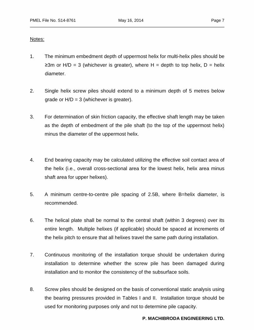
Notes:
1. The minimum embedment depth of uppermost helix for multi-helix piles should be
≥3m or H/D = 3 (whichever is greater), where H = depth to top helix, D = helix
diameter.
2. Single helix screw piles should extend to a minimum depth of 5 metres below
grade or H/D = 3 (whichever is greater).
3. For determination of skin friction capacity, the effective shaft length may be taken
as the depth of embedment of the pile shaft (to the top of the uppermost helix)
minus the diameter of the uppermost helix.
4. End bearing capacity may be calculated utilizing the effective soil contact area of
the helix (i.e., overall cross-sectional area for the lowest helix, helix area minus
shaft area for upper helixes).
5. A minimum centre-to-centre pile spacing of 2.5B, where B=helix diameter, is
recommended.
6. The helical plate shall be normal to the central shaft (within 3 degrees) over its
entire length. Multiple helixes (if applicable) should be spaced at increments of
the helix pitch to ensure that all helixes travel the same path during installation.
7. Continuous monitoring of the installation torque should be undertaken during
installation to determine whether the screw pile has been damaged during
installation and to monitor the consistency of the subsurface soils.
8. Screw piles should be designed on the basis of conventional static analysis using
the bearing pressures provided in Tables I and II. Installation torque should be
used for monitoring purposes only and not to determine pile capacity.
P. MACHIBRODA ENGINEERING LTD.

PMEL File No. S14-8761 May 16, 2014 Page 8
9. A representative of the Geotechnical Consultant should inspect and document
the installation of each screw pile on a continuous basis.
5.4 Drilled, Cast-in-Place Concrete Piles and/or Belled Caissons
Construction difficulties should be anticipated due to cobblestone, boulders,
groundwater seepage and sloughing conditions. Casing will be required to complete
the installation of some drilled piles at this site.
Drilled, straight shaft, cast-in-place, reinforced concrete piles may be designed on the
basis of skin friction only. Belled caissons may be designed on the basis of skin friction
and end bearing capacity.
The ultimate skin friction bearing pressures of the undisturbed soil are as follows:
TABLE III. SKIN FRICTION BEARING PRESSURES (DRILLED PILES)
Zone (metres) Ultimate Skin Friction Bearing Pressure Along Pile Shaft (kPa)
0 to 2 2 to 3
3 to 10 Below 10
0 40 70 90
Notes:
1. To minimize frost heave potential, skin friction piles should be extended to and
reinforced to a minimum depth of 6.0 metres below finished ground surface. 2. Piles should be reinforced.
3. A minimum pile diameter of 400 mm is recommended for the primary structural
loads. Larger pile diameters may be required to allow for the removal of cobbles
and boulders in some pile holes, if encountered.
4. The pile holes should be filled with concrete as soon as practical after drilling.
P. MACHIBRODA ENGINEERING LTD.

PMEL File No. S14-8761 May 16, 2014 Page 9
5. Casing will be required where groundwater seepage and sloughing conditions
are encountered to maintain the pile holes open for placing of the reinforcing
steel and concrete. The annular space between the casing and drilled hole must
be filled with concrete. As casing is extracted, concrete in casing must have
adequate head to displace all water in the annular space.
6. A minimum centre-to-centre pile spacing of not less than three pile diameters is
recommended.
7. A representative of the Geotechnical Consultant should inspect and document
the installation of the drilled, cast-in-place concrete piles.
TABLE IV. END BEARING PRESSURE (BELLED CAISSONS)
*Depth (metres) Ultimate End Bearing Pressure (kPa) 6 to 10
Below 10 600 750
*Bells should be formed a minimum of one bell diameter into glacial till. Belling depth may have to be adjusted depending on the position of seepage, sloughing, cobbles and boulders. Bells must be
constructed an adequate depth below the underside of any saturated sand deposits.
Notes:
1. End bearing caissons designed on the basis of 600 kPa must bear on
undisturbed, naturally deposited, stiff glacial till. End bearing caissons designed
on the basis of 750 kPa must bear on undisturbed, naturally deposited, stiff
glacial till.
2. For determination of skin friction capacity, the effective shaft length for belled
caissons may be taken as the depth of embedment of the straight sided portion
of the pile shaft, minus the pile diameter (i.e., the bottom-most portion of the pile
shaft is neglected to account for interaction with the bell).
3. End bearing caissons should be inspected to confirm the removal of loose,
disturbed soil prior to placing concrete and steel.
4. Caisson shafts should be reinforced. P. MACHIBRODA ENGINEERING LTD.

PMEL File No. S14-8761 May 16, 2014 Page 10
5. Concrete should be placed as soon as practical after cleaning the bell.
6. To prevent softening of the bearing strata, water should not be allowed to
accumulate at the base of the caisson hole. Groundwater seepage and sloughing
conditions were encountered during test drilling. Casing may be required where
groundwater seepage and sloughing conditions are encountered to maintain the
pile holes open for placing of the reinforcing steel and concrete. The annular space
between the casing and drilled hole must be filled with concrete. As casing is
extracted, concrete in casing must have adequate head to displace all water in the
annular space.
7. End bearing caissons may be belled at the base to a maximum of three times the
shaft diameter.
8. The height of the bell should be designed to provide adequate concrete to
distribute the unit stresses into the concrete without over-stressing the outer,
non-reinforced concrete within the bell.
9. Full time inspection by a representative of the Geotechnical Consultant,
employed directly by the Owner, is required to confirm ultimate bearing pressures
and to document the installation of each end bearing caisson.
5.5 Limit States/Resistance Factors and Serviceability
As per the National Building Code of Canada - NBCC (2010), the following resistance
factors are considered appropriate for the design of:
• Deep foundations:
o Compressive Resistance, Φ = 0.4
o Uplift Resistance, Φ = 0.3
P. MACHIBRODA ENGINEERING LTD.

PMEL File No. S14-8761 May 16, 2014 Page 11
For Limit States Design (LSD), a settlement analysis of the foundation must also be
evaluated to ensure the structure is not negatively impacted by excessive settlement at
the design load. This is also known as Serviceability Limit States (SLS) when designing
on the basis of LSD.
For pile foundations, provided the foundation is designed using the appropriate
resistance factors presented above, the amount of settlement of a deep foundation at
the design load will be small and within tolerable limits (typically less than 10 mm).
Hence, settlement typically does not govern in the design of deep foundations. The
exception to this would be the case where belled caisson are employed to carry the
foundation load and large bell diameters are required (i.e. in excess of 3 to 4 metres).
Foundation settlement should evaluated for this situation.
5.6 Floor System
5.6.1 Structural Floor with Void Filler
For a structural floor on compressible void filler a continuous sheet of polyethylene plastic
should be placed between the compressible void filler and the concrete floor. The
compressible void filler should be installed in accordance with the manufacturer’s
specifications.
P. MACHIBRODA ENGINEERING LTD.

PMEL File No. S14-8761 May 16, 2014 Page 12
5.6.2 Exterior Slabs/Sidewalks
Grade-supported concrete slabs exposed to freezing conditions (i.e., exterior
slabs/sidewalks, etc.) will be subject to differential movements associated with frost
action. Where potential slab movements are not deemed tolerable, the potential for
differential movements associated with frost action can be minimized by placing
sub-horizontal rigid polystyrene insulation below the slabs/sidewalks. The insulation
should have a minimum thickness of 75 mm and should extend from the foundation
wall/grade beam sub-horizontally to a minimum distance of 1.2 metres beyond the outer
edges of the slab/sidewalk. If differential movements cannot be tolerated, the
slabs/sidewalks could be constructed as structural slabs (i.e., pile supported).
5.7 Grade Beams
The grade beams should be reinforced at both top and bottom throughout their entire
length. Grade beams should be constructed to allow a minimum of 150 mm of net void
space between the underside of the grade beam and the subgrade soil.
5.8 Site Classification for Seismic Site Response
Based on the consistency of the subgrade soils encountered at this site, and
Table 4.1.8.4.A of the National Building Code of Canada (2010), the Site Classification
for seismic site response falls within Class D.
5.9 Foundation Concrete
Water-soluble salts (gypsum crystals) were encountered during test drilling. Sulphate
resistant cement is recommended for all foundation concrete in contact with the soil. All
concrete at this site should be manufactured in accordance with current CSA standards. It
should be recognized that water soluble sulphate salts combined with moist soil conditions
or low pH soils, could render the soil highly corrosive to some types of metal water lines,
elbows, connectors, etc., in contact with the soil.
P. MACHIBRODA ENGINEERING LTD.

PMEL File No. S14-8761 May 16, 2014 Page 13
5.10 Asphalt Concrete Pavement Structures
The following minimum recommendations should be incorporated into the design of the
asphalt concrete pavement structures.
1. Prepare the site in accordance with Section 5.2, Site Preparation.
2. As a subgrade support, the CBR (California Bearing Ratio) rating of the
compacted subgrade soil should be in the order of 3. Based on the CBR rating,
the following pavement structures have been presented.
TABLE V. THICKNESS DESIGN FOR PAVEMENT SURFACE STRUCTURES
Pavement Structure
Heavy Truck Traffic Wheel
Loading (5,400 kg)
(mm)
Medium Truck Traffic Wheel
Loading (3,180 kg)
(mm)
Light Truck/Passenger Vehicle Traffic Wheel
Loading (1,830 kg)
(mm) Asphalt Concrete
Granular Base (Min CBR = 65)
Granular Sub-Base
(Min CBR =30)
Prepared Subgrade
*Geotextile/Geogrid
100
200
300
(150)
As Required
80
150
250
(150)
As Required
65
150
150
(150)
As Required
Total Thickness 600 480 365
*Geotextile/geogrid is recommended where loose/soft/wet subgrade soils are encountered.
3. To minimize disturbance of the subgrade soils, all necessary excavation,
moisture conditioning, levelling and compaction of the subgrade should be
performed with light weight equipment. The excavating/hauling equipment
should not be allowed to travel on the prepared subgrade.
P. MACHIBRODA ENGINEERING LTD.

PMEL File No. S14-8761 May 16, 2014 Page 14
4. Subgrade fill, if required, should preferably consist of imported granular fill or low
plastic fine grained soil. Subgrade fill should be placed in thin lifts (150 mm
loose, maximum) and compacted to 96 percent of Standard Proctor density at
optimum moisture content.
5. Soft/wet soil conditions may be encountered during construction. Where
soft/rutting/lateral deflection is encountered during construction,
geotextile/geogrid may be required and should be subject to review by the
Geotechnical Consultant during field construction. Based on the actual
conditions encountered at the time of construction, the pavement structure may
need to be modified to accommodate the construction equipment and the
intended use.
6. All granular sub-base or base course placed above the subgrade should be
placed in thin lifts (150 mm loose) and compacted to 98 percent of standard
Proctor density at optimum moisture content. The granular base course material
should meet the aggregate graduation requirements in Table VI.
TABLE VI. AGGREGATE GRADATION REQUIREMENTS
Grain Size (mm) Percent Passing
Base Course Sub-Base Course 50.0 25.0 18.0 12.5 5.0 2.0
0.900 0.400 0.160 0.071
– 100
87 – 100 72 – 93 45 – 77 26 – 56 18 – 39 13 – 26 7 – 16 6 – 11
100 85 – 100 80 – 100 70 – 100 50 – 85 35 – 75 25 – 50 15 – 35 8 – 22 0 – 13
Plasticity Index (%) CBR (min.)
% Fracture (min.)
0 – 6 65 50
0 – 6 30 –
P. MACHIBRODA ENGINEERING LTD.

PMEL File No. S14-8761 May 16, 2014 Page 15
7. Positive surface drainage is recommended to reduce the potential for moisture
infiltration through the pavement structure.
8. Surface water should be prevented from seeping back under the outer edges of the
pavement structure.
9. Periodic maintenance such as crack sealing will be required for asphalt concrete
pavement.
6.0 LIMITATIONS The presentation of the summary of the field drill logs and foundation design
recommendations has been completed as authorized. Four, 150 mm diameter test
holes were dry drilled using our continuous flight auger drill rig. Field drill logs were
compiled for the Test Holes during test drilling which, we believe, were representative of
the subsurface conditions at the Test Hole locations at the time of test drilling.
Variations in the subsurface conditions from that shown on the drill logs at locations
other than the exact test locations should be anticipated. If conditions should differ from
those reported here, then we should be notified immediately in order that we may
examine the conditions in the field and reassess our recommendations in the light of
any new findings.
Our scope of work did not include environment considerations. Detectable evidence of
potentially environmentally sensitive materials (coal combustion residuals- cinders) was
observed during the actual time of the field test drilling program. There is a risk of
elevated concentrations of metal and polycyclic aromatic hydrocarbons (PAHs) in coal
combustion residual. Additional test holes should be drilled and samples recovered for
chemical analysis.
P. MACHIBRODA ENGINEERING LTD.

PMEL File No. S14-8761 May 16, 2014 Page 16
The subsurface investigation necessitated the drilling of deep test holes. The test holes
were backfilled at the completion of test drilling. Please be advised that some
settlement of the backfill materials will occur which may leave a depression or an open
hole. It is the responsibility of the client to inspect the site and backfill, as required, to
ensure that the ground surface at each Test Hole location is maintained level with the
existing grade.
This report has been prepared for the exclusive use of Prakash Consulting Ltd. and
their agents for specific application to the proposed Dairy Queen to be constructed at
703-100th Street in Tisdale, Saskatchewan. It has been prepared in accordance with
generally accepted geotechnical engineering practices and no other warranty, express
or implied, is made.
Any use which a Third Party makes of this report, or any reliance on decisions to be
made based on it, is the responsibility of such Third Parties. PMEL accepts no
responsibility for damages, if any, suffered by any Third Party as a result of decisions
made or actions based on this report.
The acceptance of responsibility for the design/construction recommendations
presented in this report is contingent on adequate and/or full time inspection
(as required, based on site conditions at the time of construction) by a representative of
the Geotechnical Consultant. PMEL will not accept any responsibility on this project for
any unsatisfactory performance if adequate and/or full time inspection is not performed
by a representative of PMEL.
If this report has been transmitted electronically, it has been digitally signed and
secured with personal passwords to lock the document. Due to the possibility of digital
modification, only originally signed reports and those reports sent directly by PMEL can
be relied upon without fault.
P. MACHIBRODA ENGINEERING LTD.


P. MACHIBRODA ENGINEERING LTD.CONSULTINGGEOTECHNICAL/GEOENVIRONMENTAL ENGINEERS
DRAWINGS


APPENDIX A Explanation of Terms on Test Hole Logs
P. MACHIBRODA ENGINEERING LTD.

recpt/PMEL/repref/TermsonTestHoles P. MACHIBRODA ENGINEERING LTD.
CLASSIFICATION OF SOILS
Coarse-Grained Soils: Soils containing particles that are visible to the naked eye. They include gravels andsands and are generally referred to as cohesionless or non-cohesive soils. Coarse-grained soils are soilshaving more than 50 percent of the dry weight larger than particle size 0.080 mm.
Fine-Grained Soils: Soils containing particles that are not visible to the naked eye. They include silts andclays. Fine-grained soils are soils having more than 50 percent of the dry weight smaller than particle size0.080 mm.
Organic Soils: Soils containing a high natural organic content.
Soil Classification By Particle SizeClay – particles of size < 0.002 mmSilt – particles of size 0.002 – 0.060 mm
Sand – particles of size 0.06 – 2.0 mmGravel – particles of size 2.0 – 60 mm
Cobbles – particles of size 60 – 200 mmBoulders – particles of size >200 mm
TERMS DESCRIBING CONSISTENCY OR CONDITION
Coarse-grained soils: Described in terms of compactness condition and are often interpreted from the resultsof a Standard Penetration Test (SPT). The standard penetration test is described as the number of blows, N,required to drive a 51 mm outside diameter (O.D.) split barrel sampler into the soil a distance of 0.3 m (from0.15 m to 0.45 m) with a 63.5 kg weight having a free fall of 0.76 m.
CompactnessCondition
SPT N-Index(blows per 0.3 m)
Very looseLoose
CompactDense
Very dense
0-44-10
10-3030-50
Over 50
Fine-Grained Soils: Classified in relation to undrained shear strength.
ConsistencyUndrained
ShearStrength
(kPa)
N Value(Approximate) Field Identification
Very SoftSoftFirmStiff
Very StiffHard
<1212-2525-50
50-100100-200
>200
0-22-44-8
8-1515-30>30
Easily penetrated several centimetres by the fist.Easily penetrated several centimetres by the thumb.Can be penetrated several centimetres by the thumb with moderate effort.Readily indented by the thumb, but penetrated only with great effort. Readily indented by the thumb nail.Indented with difficulty by the thumbnail.
Organic Soils: Readily identified by colour, odour, spongy feel and frequently by fibrous texture.
DESCRIPTIVE TERMS COMMONLY USED TO CHARACTERIZE SOILS
Poorly Graded - predominance of particles of one grain size.Well Graded - having no excess of particles in any size range with no intermediate sizes lacking.Mottled - marked with different coloured spots.Nuggety - structure consisting of small prismatic cubes.Laminated - structure consisting of thin layers of varying colour and texture.Slickensided - having inclined planes of weakness that are slick and glossy in appearance.Fissured - containing shrinkage cracks.Fractured - broken by randomly oriented interconnecting cracks in all 3 dimensions.

WL > 50
WL < 50
WL > 50
WL < 50
WL > 50
WL < 30
WL >30 < 50
NOT MEETING ALL GRADATION REQUIREMENTS FOR SW
ATTERBERG LIMITS BELOW "A" LINE OR PI < 4
ATTERBERG LIMITS ABOVE "A" LINE WITH PI >7
Cu = D60 >4 Cc = (D30)2 = 1 to 3
D10 D60 x D10
NOT MEETING ALL ABOVE REQUIREMENTS FOR GW
ATTERBERG LIMITS BELOW "A" LINE OR PI < 4
Cu = D60 >6 Cc = (D30)2 = 1 to 3
D10 D60 x D10
ATTERBERG LIMITS ABOVE "A" LINE WITH PI > 7
WELL-GRADED SANDS, GRAVELLY SANDS MIXTURES <5% FINES
POORLY-GRADED SANDS OR GRAVELLY SANDS <5% FINES
SILTY SANDS, SAND-SILT MIXTURES >12% FINES
CLAYEY SANDS, SAND-CLAY MIXTURES >12% FINES
WELL-GRADED GRAVELS, GRAVEL-SAND MIXTURES <5% FINES
POORLY-GRADED GRAVELS AND GRAVEL-SAND MIXTURES <5% FINES
SILTY GRAVELS, GRAVEL-SAND-SILT MIXTURES >12% FINES
CLAYEY GRAVELS, GRAVEL-SAND-CLAY MIXTURES >12% FINES
GW
GP
GM
GC
STRONG COLOUR OR ODOUR AND OFTEN FIBROUS TEXTURE
SOIL CLASSIFICATION SYSTEM (MODIFIED U.S.C.)
MAJOR DIVISION GROUP SYMBOL TYPICAL DESCRIPTION LABORATORY CLASSIFICATION CRITERIA
HIGHLY ORGANIC SOILS Pt PEAT AND OTHER HIGHLY ORGANIC SOILS
CO
AR
SE-G
RA
INED
SO
ILS
(M
OR
E TH
AN
HA
LF B
Y W
EIG
HT
LAR
GER
TH
AN
NO
. 200
SIE
VE
SIZE
)
GR
AVEL
S
M
ore
than
hal
f coa
rse
fract
ion
larg
er th
an N
o. 4
sie
ve s
ize
SAN
DS
Mor
e th
an h
alf c
oars
e fra
ctio
n sm
alle
r tha
n N
o. 4
sie
ve s
ize
CLEAN GRAVELS
DIRTY GRAVELS
CLEAN SANDS
DIRTY SANDS
SW
SP
ML
MH
SM
SC
CL
CI
FIN
E-G
RA
INED
SO
ILS
(MO
RE
THA
N H
ALF
BY
WEI
GH
T PA
SSIN
G
NO
. 200
SIE
VE S
IZE)
SILTS Below "A" line on plasticity chart;
negligible organic content
CLAYS Above 'A" line on plasticity chart;
negligible organic content
ORGANIC SILTS & ORGANIC CLAYS
Below "A" line on plasticity chart
CH
OL
OH
INORGANIC CLAYS OF HIGH PLASTICITY, FAT CLAYS
ORGANIC SILTS AND ORGANIC SILTY CLAYS OF LOW PLASTICITY
ORGANIC CLAYS OF HIGH PLASTICITY
INORGANIC SILTS AND VERY FINE SANDS, ROCK FLOUR, SILTY SANDS OF SLIGHT PLASTICITY
INORGANIC SILTS, MICACEOUS OR DIATOMACEOUS, FINE SANDY OR SILTY SOILS
INORGANIC CLAYS OF LOW PLASTICITY, GRAVELLY, SANDY, OR SILTY CLAYS, LEAN CLAYS
INORGANIC CLAYS OF MEDIUM PLASTICITY, SILTY CLAYS
0
10
20
30
40
50
60
0 10 20 30 40 50 60 70 80 90 100
LIQUID LIMIT (WL)
PLA
STIC
ITY
IND
EX (P
I)
CL-ML
MH or OH
CH
CI
ML or OL
ML
CL
"A" LINE
PLASTICITY CHARTFOR CLASSIFICATIONOF FINE GRAINED SOILS.
recpt/PMEL/repref/SoilClassChart P. MACHIBRODA ENGINEERING LTD.

APPENDIX B Topsoil, Organic Matter & Organics
P. MACHIBRODA ENGINEERING LTD.

Appendix P. MACHIBRODA ENGINEERING LTD.
A Horizon The A horizon is the topsoil layer of the soil strata. It is characterized by a build up of organic matter, and a lower unit weight than subsequent layers. The organic matter content of this layer is typically 4-10% by mass. The colour of this horizon varies from dark black to brown, depending on surface vegetation and climatic conditions. B Horizon Typically reddish brown in colour and contains accumulations of matter that have been washed down from the A Horizon. The B horizon is generally composed of clay that has been washed out of the A Horizon, but can also contain iron, calcium and sodium deposits as well. C Horizon Unweathered parent soil.
Topsoil is a mixture of mineral soil and organic matter. The organic matter is developed from decaying biological material (leaves, grass, trees, animals, etc.) and contributes to the brown to black colour of the soil. Following the topsoil is the B horizon which is a transition layer, where staining from the overlying topsoil is common. This results in a darker colour of the soil immediately below the organic topsoil layer. Depending on the surface vegetation, rootlets may be present below the depth of topsoil. However it should be recognized that these rootlets are not the same as organic matter in topsoil. Physically speaking in comparison to mineral soil, topsoil has a significantly lower bulk density and a lower unit weight as compared to the underlying parent soil. This is due to larger pore spaces and non mineral materials in the soil matrix. Along with lower density, topsoil is often spongy and colloidal/fibrous. The following figure is of a typical prairie soil. Each horizon is labelled accordingly to demonstrate a typical soil profile. Reference Henry L. 2003. Henry’s Handbook of Soil and Water, Henry Perspectives, Saskatoon, SK.