Owner's Manual - AVR 255, AVR 355 (English EU)
58
AVR 255/AVR 355 Audio/ Video Receiver OWNER’S MANUAL Composit AVR Info Resolution Audio Effects Video Modes Surround Modes Back/Exit Source List A B L K OK ENGLISH
-
Upload
calin-huidu -
Category
Documents
-
view
89 -
download
4
Transcript of Owner's Manual - AVR 255, AVR 355 (English EU)
AVR 255/AVR 355 Audio/VideoReceiverOWNER’S MANUAL
Composit
AVR Info Resolution Audio Effects Video Modes Surround Modes Back/Exit Source ListA B L KOKEN
GLI
SH

Table of Contents
Typographical ConventionsIn order to help you use this manual with the remote control, front-panel controls and rear-panelconnections, certain conventions have been used.
EXAMPLE – (bold type) indicates a specific remote control or front-panel button, or rear-panelconnection jack
EXAMPLE – (OCR type) indicates a message that is visible on the front-panel information display
1 – (number in a square) indicates a specific front-panel control
– (number in a circle) indicates a rear-panel connection
A – (letter in a square) indicates a button or indicator on the remote
A – (letter in an oval) indicates a button on the Zone 2 remote
The appearance of the text or cursor for your receiver’s on-screen menus may vary slightly from theillustrations in this manual.Whether the text appears in all uppercase or upper- and lowercasecharacters, performance and operation remain the same.
2 TABLE OF CONTENTS
3 Introduction4 Safety Information5 Unpacking6 Front Panel Controls8 Rear Panel Connections
11 Main Remote Control Functions13 Zone 2 Remote Control Functions15 Installation and Connections15 Audio Equipment Connections15 HDMI Input Connections15 HDMI Output Connections16 Analog and Digital Input Connections17 Video Equipment Connections18 System and Power Connections18 Main Room Remote Control Extension18 Zone 2 IR Link18 Multiroom Audio Connection18 A-BUS Installation Connections19 Speaker Selection19 Speaker Placement20 System Configuration20 First Turn On20 Using the On-Screen Display20 System Setup20 Source Selection21 Audio and Video Input Selection21 Set Up Sources21 Audio Effects21 Video Mode21 Surround Mode21 Audio Format From Source21 Video Input From Source21 Audio Input From Source21 Resolution To Display22 Resolution From Source22 Adjust Lip Sync22 Change Source Name22 Zone 2 Audio22 Speaker Setup, EzSet/EQ22 Speaker Setup, Manual28 Operation28 Surround Mode Chart30 Basic Operation30 Mute Function30 Audio Effects30 Video Modes30 Source Selection30 Video Input Selection31 Video Troubleshooting Tips31 Multichannel Disc Players with/without
HDMI31 6/8-Channel Direct Input31 Controls and Use of Headphones31 Surround Mode Selection32 Digital Audio Signals33 Surround modes34 Tape Recording34 The Bridge35 Multiroom Operation35 Multiroom Setup35 Surround Amplifier Channel Assignment37 Video Adjustments37 Video Modes38 Audio Adjustments38 Audio Effects38 Advanced Features38 System Settings38 Front Panel Dimmer
38 Volume Units38 Volume Default and Level38 Unit of Measure38 iPod Charging38 On-Screen Language38 HDMI Audio to TV38 Resolution to Display39 Menu Appearance39 OSD Transparency39 Volume Status Messages39 Menus39 Setup and Slide-In Menus39 Screen Saver39 Default Surround Mode40 Tuner Operation40 To Select the Built-In Tuner40 RDS Functions42 Programming the Remote
42 Programming with Codes42 Direct Code Entry42 Auto Search Method42 Code Readout43 Learning Codes from a Remote43 Erasing Learned Codes44 Activity Programming (Macros)44 Programmed Device Functions45 Notes on Using the AVR Remote With
Other Devices45 Punch-Through Programming45 Resetting the Remote Memory46 AVR 355 Remote Function List48 AVR 255 Remote Function List50 Troubleshooting Guide50 Processor Reset51 Technical Specifications52 Appendix - Settings Worksheet
Declaration of Conformity
We, Harman Consumer Group, Inc.2, route de Tours72500 Château-du-Loir,FRANCE
declare in own responsibility, that the product described in thisowner’s manual is in compliance with technical standards:
EN55013(2001) & + A2(2006)
EN55020(2002) & + A2(2005)
EN60065:2002
EN61000-3-2(2000)+A2(2005)
EN61000-3-3 (1995)+A1(2001)+A2(2005)
EN61000-4-2(1995) & + A1(1998) & + A2(2001)
EN61000-4-3(2002) & + A1(2002)
EN61000-4-4(2004)
Jurjen AmsterdamHarman Consumer Group, Inc.
03/08

Introduction
Thank you for choosing Harman Kardon!With the purchase of a Harman Kardon AVR 255/AVR 355 you are about to begin many years oflistening enjoyment. Designed to provide all theexcitement and detail of movie soundtracks andevery nuance of musical selections, the AVR 255/AVR 355 are truly multichannel receivers for thenew millennium. In addition to the traditional 5.1digital decoding modes such as Dolby Digital andDTS, they offer the latest advancements in sur-round technology such as Dolby® True HD andDTS®-HD Master Audio™ and the latest 7.1channel versions of Harman's own Logic 7technology.
The AVR 255/AVR 355 have been engineered sothat it is easy to take advantage of all thepower of their digital technology. Full-color,high-definition, multi-language on-screenmenus, fully color coded connection jacks andterminals make installation fast and simple.However, to obtain the maximum enjoymentfrom your new receiver, we urge you to read thismanual. A few minutes spent learning the func-tions of the various controls will enable you totake advantage of all the power the AVR is ableto deliver.
If you have any questions about this product, itsinstallation or its operation, please contact yourretailer or custom installer. They are your bestlocal sources of information.
Description and FeaturesThe AVR serves as the hub of your home enter-tainment system, providing a wide range of lis-tening possibilities for almost any audio or videoprogram source, whether it is the broadcast of amovie or sporting event in HDTV or a vintagemono or stereo recording.When playing digitalaudio sources from either the conventional opti-cal and coaxial inputs, or through the HDMI 1.3acompliant connections, the AVR decodes DolbyTrue HD, Dolby Digital Plus, DTS-HD MasterAudio and DTS-HD data streams. Two-channelstereo and matrix surround sources benefit fromall current Dolby Pro Logic IIx modes and DTSNeo:6. The latest version of our proprietary Logic7® process is on-board to create a wider, moreenveloping sound field and more defined sur-round channel positioning, regardless of the typeof source material.
Dolby Virtual Speaker is available to createenveloping sound fields from front left and rightspeakers, and the latest Dolby Headphonecircuitry creates an amazing sense of opennesswith headphones.
The AVR takes the “video” part of its name seri-ously. Along with three HDMI inputs and three100MHz analog component video inputs (twoon the AVR 255), the AVR’s video processingallows you to scale the output signal to 1080ploop-through to match the requirements of yourspecific video display. Thanks to award winningFaroudja® DCDi Cinema™ technology, yourvideo sources never looked better. Tying audioand video together, the AVR provides A/V syncdelay so that the lip sync errors – commonlyseen when digital video processing is used in asource, program or video display – areeliminated.
An important addition to the AVR’s impressivelist of features is EzSet/EQ™, which automatesthe configuration process to make it quicker, eas-ier and more precise. Using the special micro-phone supplied with the unit, EzSet/EQ takes theguesswork out of entering speaker “size” andcrossover information, delay times for all chan-nels and output levels. In addition to the config-uration settings, EzSet/EQ also includes roomequalization so that the signals sent to eachspeaker are tailored to provide accurate sonicquality with your specific combination of speakertype, room size and other factors that influenceroom acoustics.With EzSet/EQ, your system iscustom-configured in a few minutes with accu-racy that previously required expensive andhard-to-use test equipment.
In tandem with EzSet/EQ, the AVR includes a fullset of manual configuration settings for thosewho wish to custom-trim their system even fur-ther. A Quadruple Crossover bass managementsystem makes it possible to enter differentcrossover settings for each speaker group.
A Stereo-Direct mode bypasses the digitalprocessor to preserve all of the subtleties of olderanalog, two-channel materials, while bassmanagement, available in the surround andStereo-Digital modes, improves your ability totailor the sound to suit your room acoustics ortaste.
For the ultimate in flexibility, the AVR’s featureconnections for four video devices, all with bothcomposite and S-Video inputs. Two additionalaudio inputs are available, and a total of sixdigital inputs and two outputs make the AVRcapable of handling all the latest digital audiosources. For compatibility with the latest HDTVvideo sources and progressive scan DVD players,the AVR also features wide-bandwidth, low-crosstalk component video switching.
Coax and optical digital outputs are available fordirect connection to digital recorders. A videorecording output and a color-coded eight-chan-nel input make the AVR virtually future-proof,with everything needed to accommodate tomor-row’s new formats right on board.
With one simple connection between theAVR 355 and the optional Harman Kardon
, you are able to listen to materialsstored on your compatible Apple® iPod®**.Your AVR’s system remote control has beenpreprogrammed with control codes that enableyou to select tracks for playback and navigatemany of your iPod’s functions, even from acrossthe room. The Bridge™ will even let you chargeyour iPod.
The AVR 355’s flexibility and power extendbeyond your main home theater or listeningroom. The AVR includes a sophisticated multi-zone control system that allows you to selectone source for use in the main room and adifferent one (Audio only) in a second room.Complete control over volume is possible with aseparate infrared control link. To make it easy tooperate the AVR from a remote room, a separate“Zone II” remote is included.Additional multiroom options include the optionto assign two of the AVR’s output channels to themultiroom system and the ability to link the AVRto innovative A-BUS® keypads for multiroom oper-ation without the need for external amplifiers.
The AVR’s powerful amplifier uses traditionalHarman Kardon high-current design technolo-gies to meet the wide dynamic range of any pro-gram selection.
Harman Kardon invented the high-fidelityreceiver more then fifty years ago.With state-of-the-art circuitry and time-honored circuitdesigns, the AVR 255 and AVR 355 are theperfect combination of the latest in digital audiotechnology, a quiet yet powerful analogamplifier in an elegant, easy-to-use package.
**Compatible with all iPod models equipped with a dock connector, including third-generation “Click Wheel” models and newer. Not compatible with iPodshuffle models. Although iPod photo models are compatible, images stored on the iPod can only be viewed using the controls on the iPod, not with theAVR remote.
ENGLI
SH
INTRODUCTION 3
Safety Information
Dolby True HD, Dolby Digital Plus, DolbyDigital EX and Dolby Pro Logic* II andIIx Decoding, and the full suite of DTS®
modes, including DTS-HD Master Audio,DTS-HD and DTS-ES® 6.1 Discrete &Matrix and Neo:6®
Seven channels of high-current amplifi-cation with two channels assignable toeither surround back or multiroomapplications
Harman Kardon’s exclusive Logic 7®
processing, along with a choice ofDolby Virtual Speaker processing foruse when only two speakers areavailable
Dolby Headphone to create spacious,open sound fields when using head-phones
Harman Kardon’s advanced EzSet/EQ™
automatically configures speaker set-tings and sets room equalization forquick, easy and accurate system setup
HDMI with audio/video processing,upscaling to 720p/1080p and repeaterfor increased cable length without sig-nal degradation
Three HDMI™ 1.3a and three (two onAVR 255) assignable high-bandwidthanalog component inputs for compati-bility with the latest high-definitionvideo sources
Front panel analog A/V inputs Front panel digital inputs for easy con-
nection to portable digital devices andthe latest video game consoles
Connects to Harman Kardon’s(optional) for charging, playback andcontrol of a compatible Apple® iPod®
device (AVR 355 only) Input titling for all input sources
(except tuner) Multiple digital inputs and outputs Full-color, high-definition, multi-lan-
guage On-screen menu and display sys-tem
A/V Sync delay adjustable for eachinput delivers perfect lip sync withdigital programs or video displays
6-Channel/8-Channel Direct Input forUse with Future Audio Formats
Extensive bass management options,including four separate crossovergroupings
Extensive multiroom options, includinga standard Zone II remote, assignableamplifier channels and A-BUS Ready®
capability for listening to a separatesource in a remote zone (AVR 355 only)
Main Remote with Internal Codes
Important Safety Instructions
Please read the following precau-tions before use:
1. Read these instructions.
2. Keep these instructions.
3. Heed all warnings.
4. Follow all instructions.
5. Do not use this apparatus near water.
6. Clean only with a dry cloth.
7. Do not block any ventilation openings. Installin accordance with the manufacturer’sinstructions.
8. Do not install near any heat sources such asradiators, heat registers, stoves or otherapparatus (including amplifiers) that produceheat.
9. Do not defeat the safety purpose of thepolarized or grounding-type plug. A polarizedplug has two blades with one wider than theother. A grounding-type plug has two bladesand a third grounding prong. The wide bladeor the third prong is provided for your safety.If the provided plug does not fit into youroutlet, consult an electrician for replacementof the obsolete outlet.
10.Protect the power cord from being walked onor pinched, particularly at plugs, conveniencereceptacles and the point where they exitfrom the apparatus.
11.Only use attachments/accessories specifiedby the manufacturer.
12.Use only with the cart, stand, tripod, bracketor table specified by the manufacturer or soldwith the apparatus.When a cart isused, use caution when moving thecart/apparatus combination toavoid injury from tip-over.
13.Unplug this apparatus during lightningstorms or when unused for long periods oftime.
14.Refer all servicing to qualified servicepersonnel. Servicing is required when theapparatus has been damaged in any way,such as power supply cord or plug isdamaged, liquid has been spilled or objectshave fallen into the apparatus, the apparatushas been exposed to rain or moisture, doesnot operate normally, or has been dropped.
15.Do not expose this apparatus to dripping orsplashing and ensure that no objects filledwith liquids, such as vases, are placed on theapparatus.
16.To completely disconnect this apparatus fromthe AC Mains, disconnect the power supplycord plug from the AC receptacle.
17.The mains plug of the power supply cordshall remain readily operable.
18.Do not expose batteries to excessive heatsuch assunshine, fire or the like.
4 SAFETY INFORMATION
Safety Information
The lightning flash with arrowheadsymbol, within an equilateral triangle,is intended to alert the user to the
presence of uninsulated “dangerous voltage”within the product’s enclosure that may be ofsufficient magnitude to constitute a risk ofelectric shock to persons.
The exclamation point within anequilateral triangle is intended to alertthe user to the presence of important
operating and maintenance (servicing)instructions in the literature accompanying theproduct.
WARNING: To reduce the risk of fire or electricshock, do not expose this apparatus to rain ormoisture.
Instructions for users on removaland disposal of used batteries.Specification of included batterytypes.
These symbols shown on the product, the packag-ing or in the manual or separate information sheetmean that the product itself, as well as the batter-ies included or built into the product, should neverbe thrown away with general household waste.Take them to applicable collection points, whereproper treatment, recycling and recovery takesplace, in accordance with national or local legisla-tion, or European Directives 2002/96/EC and2006/66/EC.
Correct handling of the product and batteries tobe disposed helps save resources and preventspossible negative effects on the environment orhuman health.
The batteries included with your equipment maybe Alkaline, Carbon Zinc/Manganese or Lithium(button cells) type.All types should be disposed ofaccording to the above instructions.
To remove the batteries from your equipment orremote control, reverse the procedure describedfor inserting batteries in the Owners Manual.
For products with a built-in battery that lasts forthe lifetime of the product, removal may not bepossible for the user. In this case, recycling orrecovery centers handle the dismantling of theproduct and the removal of the battery. If, for anyreason, it becomes necessary to replace such abattery, this procedure must be performed byauthorized service centers.
Pb
ENGLI
SH
SAFETY INFORMATION 5
Installation Location To assure proper operation and to avoid thepotential for safety hazards, place the unit ona firm and level surface.When placing theunit on a shelf, be certain that the shelf andany mounting hardware can support theweight of the product.
Make certain that proper space is providedboth above and below the unit for ventilation.If this product will be installed in a cabinet orother enclosed area, make certain that thereis sufficient air movement within the cabinet.Under some circumstances a fan may berequired.
Do not place the unit directly on a carpetedsurface.
Avoid installation in extremely hot or coldlocations, or an area that is exposed to directsunlight or heating equipment.
Avoid moist or humid locations.
Do not obstruct the ventilation slots on thetop of the unit, or place objects directly overthem.
Due to the weight of the AVR and the heatgenerated by the amplifiers, there is the remotepossibility that the rubber padding on the bot-tom of the unit’s feet may leave marks on cer-tain wood or veneer materials. Use cautionwhen placing the unit on soft woods or othermaterials that may be damaged by heat orheavy objects. Some surface finishes may beparticularly sensitive to absorbing such marksdue to a variety of factors beyondHarman Kardon's control, including the natureof the finish, cleaning materials used, andnormal heat and vibration caused by the use ofthe product, or other factors.We recommendthat caution be exercised in choosing aninstallation location for the component and innormal maintenance practices, as yourwarranty will not cover this type of damage tofurniture.
CleaningWhen the unit gets dirty, wipe it with a clean,soft, dry cloth. If necessary, wipe it with a softcloth dampened with mild soapy water, then afresh cloth with clean water.Wipe dry immediately with a dry cloth. NEVERuse benzene, aerosol cleaners, thinner, alcohol orany other volatile cleaning agent. Do not useabrasive cleaners, as they may damage the finishof metal parts. Avoid spraying insecticide nearthe unit.
Moving the UnitBefore moving the unit, be certain to disconnectany interconnection cords with other compo-nents, and make certain that you disconnect theunit from the AC outlet.
UnpackingThe carton and shipping materials used to pro-tect your new receiver during shipment werespecially designed to cushion it from shock andvibration.We suggest that you save the cartonand packing materials for use in shipping if youmove, or should the unit ever need repair.
To minimize the size of the carton in storage,you may wish to flatten it. This is done by care-fully slitting the tape seams on the bottom andcollapsing the carton. Other cardboard insertsmay be stored in the same manner. Packingmaterials that cannot be collapsed should besaved along with the carton in a plastic bag.
If you do not wish to save the packagingmaterials, please note that the carton and othersections of the shipping protection are recycla-ble. Please respect the environment and discardthose materials at a local recycling center.
It is important that you remove the protective plas-tic film from the front-panel lens. Leaving the filmin place will affect the performance of your remotecontrol.

Front Panel Controls
1234567
89)!@#$
%^&*(Ó
Volume ControlSystem Power ControlPower IndicatorHeadphone JackMenu Navigation ButtonsOK ButtonAVR Button
Info ButtonResolution ButtonAudio Effects ButtonVideo Modes ButtonSource List ButtonMain Information DisplaySpeaker/Channel Input Indicator
Surround Mode ButtonBack/Exit ButtonDigital Optical Front InputDigital Coax Front InputVideo Front Input JacksRemote Sensor Window
Composite Analog
AVR Info Resolution Audio Effects Video Modes Surround Modes Back/Exit Source ListA B L KOK
J C D 0
2 1 6 7 8 9 A E 4 5 B
IG H3
F 4
6 FRONT PANEL CONTROLS

1 Volume Control: Turn this knob clockwiseto increase the volume, counterclockwise todecrease the volume. If the AVR is muted,adjusting volume control will automaticallyrelease the unit from the silenced condition.
2 System Power Control:When the MainPower Switch on the rear panel is “ON,” pressthis button to turn on the AVR; press it again toturn the unit off (to Standby). Note that thePower Indicator 3 will turn white when theunit is on.
3 Power Indicator: This LED will be illuminatedin amber when the unit is in the Standby modeto signal that the unit is ready to be turned on.When the unit is in operation, the indicator willturn white.
4 Headphone Jack: This jack may be used tolisten to the AVR’s output through a pair of head-phones. Be certain that the headphones have astandard 6,3 mm stereo phone plug. Note thatthe speakers will automatically be turned offwhen the headphones are connected.
When configuring your system using EzSet/EQ,the calibration microphone should be pluggedinto this jack using the supplied adaptor thatconverts the small mini-plug at the end of themicrophone’s cord to a 6,3 mm plug.
5 Navigation: These buttons are used to navi-gate the AVR’s menus and to operate the tuner.
6 OK Button: Press this button to select thecurrently highlighted item.
7 AVR Settings Button: Press this button toaccess the AVR’s main menu.
8 Info Settings Button: Press this button todirectly access the AVR’s Setup Source submenu,which contains the settings for the currentsource.
9 Resolution: Pressing this Button once andthen using the Up/Down Navigation Buttons5 changes the AVR’s video output resolution tothese settings: 576i, 576p, 720p, 1080i or1080p. The AVR is set to default to 576i whenfirst switched on, or if you reset it later. This reso-lution has been chosen to ensure that the OnScreen Display information is visible on your TVeven with analog S-Video or Composite (CVBS)signals. Having selected the best resolution foryour system, confirm with the OK Button6. TheFront Panel Display now shows "Res Change,Cancel". If you press OK now, or do nothing for20 seconds, the AVR returns to normal playmode. To confirm the new resolution, press theL Button5, which changes the Display from"Cancel" to "Accept", then press the OK Button6. The new resolution is now in use.
) Audio Effects: Press this button to directlyaccess the Audio Effects submenu, which allowsadjustment of the tone and other controls. Seethe Initial Setup section for more information.
! Video Modes: Press this button for directaccess to the Video Modes submenu, which con-tains settings that may be used to improve thepicture if necessary after you have adjusted thepicture settings using the video display or TV.
@ Source List Button: Press this Button toopen the on-screen Source Selection Menu withthe slide-in Source List already open. If you arenot using your TV for on-screen reference, usethe Front Panel Information Display which showsthe information you need. Scroll up and downwith theKL Buttons5, select the desiredInput by pressing the OK Button6 and exit theSource Selection function by pressing the SourceList Button@ again.
# Main Information Display: This displaydelivers messages and status indications to helpyou operate the receiver.
$ Speaker/Channel Input Indicators: Theseindicators are multipurpose, indicating either thespeaker type selected for each channel or theincoming data-signal configuration. The left, center,right, right surround and left surround speakerindicators are composed of three boxes, while thesubwoofer is a single box. The center box lightswhen a “Small” speaker is selected, and the twoouter boxes light when “Large” speakers areselected.When none of the boxes are lit for thecenter, surround or subwoofer channels, no speakerhas been selected for that position. (See page 22for more information on configuring speakers.) Theletters inside each of the center boxes displayactive input channels. For standard analog inputs,only the L and R will light, indicating a stereoinput.When a digital source is playing, the indica-tors will light to display the channels beingreceived at the digital input.When the lettersflash, the digital input has been interrupted.(See page 33 for more information on the ChannelIndicators).
NOTE:When you have reassigned the surroundback speakers to the remote zone using theMULTI ROOM SETUP menu, the boxes thatindicate the presence of the surround back speak-ers will automatically disappear, reflecting the factthat the main listening area is now configured for5.1-channel operation. (See page 35 for moreinformation on reassigning the surround backspeakers for multiroom use.)
% Surround Modes: Press this button toselect a surround sound (e.g.,multichannel)mode. The Surround Modes menu will appear onscreen, and the menu line will appear on thelower line of the front-panel display.
Use the front-panel or remoteK/L Buttons tohighlight a different menu line: Auto Select,Virtual Surround, Stereo, Movie, Music or VideoGame. Each line represents a type of audio sig-nal, and is set to the surround mode the AVR willautomatically select when it detects the audiosignal.
You may manually select a different mode foreach type of audio. Press the OK Button whenthe menu line is highlighted, and the availablesurround mode options for the current signal willappear. Use theK/L Buttons to select thedesired mode, and press the OK Button toengage it. Press the Back/Exit Button to exit theSurround Modes menu and display the next high-er menu in the hierarchy.
See the Advanced Functions section for moreinformation on surround modes.
^ Back/Exit: Press this button to return to theprevious menu.When the main AVR menu is dis-played, press this button to exit the menu system.
& Digital Optical Front Input: Connect theoptical digital audio output of an audio or videoproduct to this jack.
* Digital Coax Front Input: This jack is nor-mally used for connection to the output ofportable digital audio devices, video game con-soles or other products that have a coax digitaljack.
( Video Front Input Jacks: Theseaudio/video jacks may be used for temporaryconnection to video games or portableaudio/video products such as camcorders andportable audio players.
Ó Remote Sensor Window: The sensorbehind this window receives infrared signals fromthe remote control. Aim the remote at this areaand do not block or cover it unless an externalremote sensor is installed.
Front Panel Controls
ENGLI
SH
FRONT PANEL CONTROLS 7
Rear Panel Connections
0
Z
Q P
7
T
S
Y
5
B
9
a 8
X
L J e Kg
IW 4 V U D O F AE N G R C H M
1
23
b
6
cf
d
,
!#"$%&'()
*+
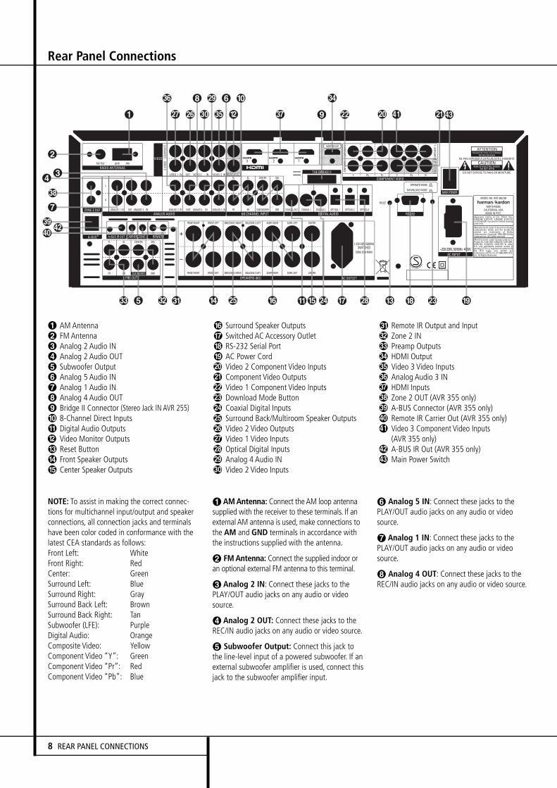
AM AntennaFM AntennaAnalog 2 Audio INAnalog 2 Audio OUTSubwoofer OutputAnalog 5 Audio INAnalog 1 Audio INAnalog 4 Audio OUTBridge II Connector (Stereo Jack IN AVR 255)8-Channel Direct InputsDigital Audio OutputsVideo Monitor OutputsReset ButtonFront Speaker OutputsCenter Speaker Outputs
Surround Speaker OutputsSwitched AC Accessory OutletRS-232 Serial PortAC Power CordVideo 2 Component Video InputsComponent Video OutputsVideo 1 Component Video InputsDownload Mode ButtonCoaxial Digital InputsSurround Back/Multiroom Speaker OutputsVideo 2 Video OutputsVideo 1 Video InputsOptical Digital InputsAnalog 4 Audio INVideo 2 Video Inputs
Remote IR Output and InputZone 2 INPreamp OutputsHDMI OutputVideo 3 Video InputsAnalog Audio 3 INHDMI InputsZone 2 OUT (AVR 355 only)A-BUS Connector (AVR 355 only)Remote IR Carrier Out (AVR 355 only)Video 3 Component Video Inputs(AVR 355 only)A-BUS IR Out (AVR 355 only)Main Power Switch
NOTE: To assist in making the correct connec-tions for multichannel input/output and speakerconnections, all connection jacks and terminalshave been color coded in conformance with thelatest CEA standards as follows:Front Left: WhiteFront Right: RedCenter: GreenSurround Left: BlueSurround Right: GraySurround Back Left: BrownSurround Back Right: TanSubwoofer (LFE): PurpleDigital Audio: OrangeComposite Video: YellowComponent Video “Y”: GreenComponent Video “Pr”: RedComponent Video “Pb”: Blue
AMAntenna: Connect theAM loop antennasupplied with the receiver to these terminals. If anexternal AM antenna is used, make connections tothe AM and GND terminals in accordance withthe instructions supplied with the antenna.
FMAntenna: Connect the supplied indoor oran optional external FM antenna to this terminal.
Analog 2 IN: Connect these jacks to thePLAY/OUT audio jacks on any audio or videosource.
Analog 2 OUT: Connect these jacks to theREC/IN audio jacks on any audio or video source.
Subwoofer Output: Connect this jack tothe line-level input of a powered subwoofer. If anexternal subwoofer amplifier is used, connect thisjack to the subwoofer amplifier input.
Analog 5 IN: Connect these jacks to thePLAY/OUT audio jacks on any audio or videosource.
Analog 1 IN: Connect these jacks to thePLAY/OUT audio jacks on any audio or videosource.
Analog 4 OUT: Connect these jacks to theREC/IN audio jacks on any audio or video source.
8 REAR PANEL CONNECTIONS
Rear Panel Connections
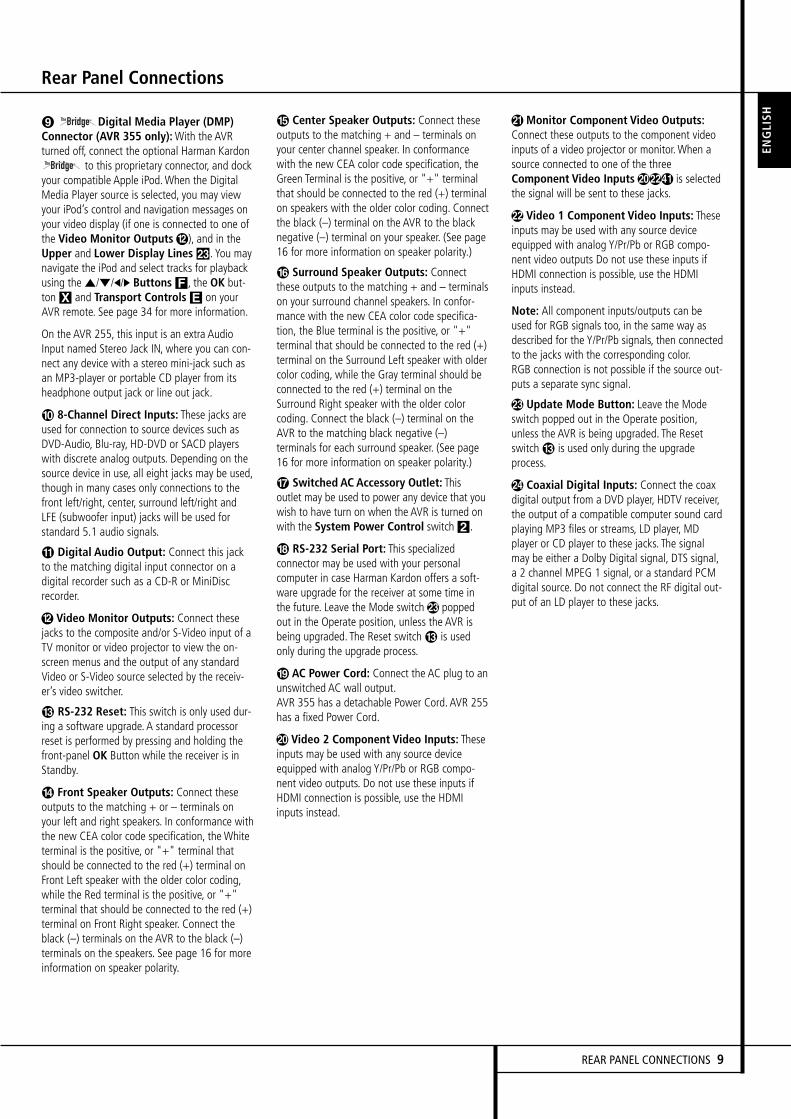
Digital Media Player (DMP)Connector (AVR 355 only):With the AVRturned off, connect the optional Harman Kardon
to this proprietary connector, and dockyour compatible Apple iPod.When the DigitalMedia Player source is selected, you may viewyour iPod’s control and navigation messages onyour video display (if one is connected to one ofthe Video Monitor Outputs), and in theUpper and Lower Display Lines Ò. You maynavigate the iPod and select tracks for playbackusing the ⁄/¤/‹/› Buttons F, the OK but-tonX and Transport Controls E on yourAVR remote. See page 34 for more information.
On the AVR 255, this input is an extra AudioInput named Stereo Jack IN, where you can con-nect any device with a stereo mini-jack such asan MP3-player or portable CD player from itsheadphone output jack or line out jack.
8-Channel Direct Inputs: These jacks areused for connection to source devices such asDVD-Audio, Blu-ray, HD-DVD or SACD playerswith discrete analog outputs. Depending on thesource device in use, all eight jacks may be used,though in many cases only connections to thefront left/right, center, surround left/right andLFE (subwoofer input) jacks will be used forstandard 5.1 audio signals.
Digital Audio Output: Connect this jackto the matching digital input connector on adigital recorder such as a CD-R or MiniDiscrecorder.
Video Monitor Outputs: Connect thesejacks to the composite and/or S-Video input of aTV monitor or video projector to view the on-screen menus and the output of any standardVideo or S-Video source selected by the receiv-er’s video switcher.
RS-232 Reset: This switch is only used dur-ing a software upgrade. A standard processorreset is performed by pressing and holding thefront-panel OK Button while the receiver is inStandby.
Front Speaker Outputs: Connect theseoutputs to the matching + or – terminals onyour left and right speakers. In conformance withthe new CEA color code specification, the Whiteterminal is the positive, or "+" terminal thatshould be connected to the red (+) terminal onFront Left speaker with the older color coding,while the Red terminal is the positive, or "+"terminal that should be connected to the red (+)terminal on Front Right speaker. Connect theblack (–) terminals on the AVR to the black (–)terminals on the speakers. See page 16 for moreinformation on speaker polarity.
Center Speaker Outputs: Connect theseoutputs to the matching + and – terminals onyour center channel speaker. In conformancewith the new CEA color code specification, theGreen Terminal is the positive, or "+" terminalthat should be connected to the red (+) terminalon speakers with the older color coding. Connectthe black (–) terminal on the AVR to the blacknegative (–) terminal on your speaker. (See page16 for more information on speaker polarity.)
Surround Speaker Outputs: Connectthese outputs to the matching + and – terminalson your surround channel speakers. In confor-mance with the new CEA color code specifica-tion, the Blue terminal is the positive, or "+"terminal that should be connected to the red (+)terminal on the Surround Left speaker with oldercolor coding, while the Gray terminal should beconnected to the red (+) terminal on theSurround Right speaker with the older colorcoding. Connect the black (–) terminal on theAVR to the matching black negative (–)terminals for each surround speaker. (See page16 for more information on speaker polarity.)
Switched AC Accessory Outlet: Thisoutlet may be used to power any device that youwish to have turn on when the AVR is turned onwith the System Power Control switch2.
RS-232 Serial Port: This specializedconnector may be used with your personalcomputer in case Harman Kardon offers a soft-ware upgrade for the receiver at some time inthe future. Leave the Mode switch poppedout in the Operate position, unless the AVR isbeing upgraded. The Reset switch is usedonly during the upgrade process.
AC Power Cord: Connect the AC plug to anunswitched AC wall output.AVR 355 has a detachable Power Cord. AVR 255has a fixed Power Cord.
, Video 2 Component Video Inputs: Theseinputs may be used with any source deviceequipped with analog Y/Pr/Pb or RGB compo-nent video outputs. Do not use these inputs ifHDMI connection is possible, use the HDMIinputs instead.
Monitor Component Video Outputs:Connect these outputs to the component videoinputs of a video projector or monitor.When asource connected to one of the threeComponent Video Inputs,) is selectedthe signal will be sent to these jacks.
Video 1 Component Video Inputs: Theseinputs may be used with any source deviceequipped with analog Y/Pr/Pb or RGB compo-nent video outputs Do not use these inputs ifHDMI connection is possible, use the HDMIinputs instead.
Note: All component inputs/outputs can beused for RGB signals too, in the same way asdescribed for the Y/Pr/Pb signals, then connectedto the jacks with the corresponding color.RGB connection is not possible if the source out-puts a separate sync signal.
Update Mode Button: Leave the Modeswitch popped out in the Operate position,unless the AVR is being upgraded. The Resetswitch is used only during the upgradeprocess.
Coaxial Digital Inputs: Connect the coaxdigital output from a DVD player, HDTV receiver,the output of a compatible computer sound cardplaying MP3 files or streams, LD player, MDplayer or CD player to these jacks. The signalmay be either a Dolby Digital signal, DTS signal,a 2 channel MPEG 1 signal, or a standard PCMdigital source. Do not connect the RF digital out-put of an LD player to these jacks.
ENGLI
SH
REAR PANEL CONNECTIONS 9

Rear Panel Connections
Surround Back/Multiroom SpeakerOutputs: These speaker terminals are normallyused to power the surround back left/surroundback right speakers in a 7.1 channel system.However, they may also be used to power thespeakers in a second zone, which will receive theoutput selected for a multiroom system.To change the output fed to these terminalsfrom the default of the Surround Back speakersto the Multiroom Output, you must change asetting in the MULTIROOM MENU of theOSD system. See page 35 for more informationon configuring this speaker output. In normalsurround system use, the brown and black termi-nals are the surround back left channel positive(+) and negative (–) connections and the tanand black terminals are the surround back rightpositive (+) and negative (–) terminals.For multiroom use, connect the brown and blackSBL terminals to the red and black connectionson the left remote zone speaker and connect thetan and black SBR terminals to the red and blackterminals on the right remote zone speaker.
Video 1 Video Outputs: Connect thesejacks to the RECORD/INPUT composite orS-Video jack on a VCR.
Video 1 Video Inputs: Connect these jacksto the PLAY/OUT composite or S-Video jacks ona TV or other video source.
Optical Digital Inputs: Connect theoptical digital output from a DVD player, HDTVreceiver, the output of a compatible computersound card playing MP3 files or streams, LDplayer, MD player or CD player to these jacks.The signal may be either a Dolby Digital signal, aDTS signal, a 2 channel MPEG 1 signal, or astandard PCM digital source.
Analog 4 Audio Inputs: Connect thesejacks to the PLAY/OUT audio jacks on a TV orother audio or video source.
Video 2 Video Inputs: Connect these jacksto the PLAY/OUT composite or S-Video jacks ona second VCR or other video source.
Remote Input and Output: If the AVR’sfront-panel IR sensor is blocked due to cabinetdoors or other obstructions, an external IR sen-sor may be used. Connect the output of thesensor to the Remote IN jack.The Output connection permits the IR sensor inthe receiver to serve other remote controlleddevices. Connect this jack to the “IR IN” jack onHarman Kardon or other compatible equipment.
Zone 2 IR Input: Connect the output of an IRsensor in a remote room to this jack to operatethe AVR’s multiroom control system.
! Preamp Outputs: Connect these jacks toan optional, external power amplifier for appli-cations where higher power is desired.
# HDMI Output: Connect this jack to theHDMI input on a compatible HDMI-equippedvideo display.
" Video 3 Video Inputs: Connect these jacksto the PLAY/OUT composite or S-Video jacks onany video source.
$ Analog 3 Audio Inputs: Connect thesejacks to the PLAY/OUT audio jacks on anyaudio or video source.
% HDMI Inputs: Connect the HDMI output ofvideo sources such as a DVD player, set-top boxor HDTV tuner to either of these jacks.
& Zone 2 Outputs (AVR 355 only): Connectthese jacks to an optional audio power amplifierto listen to the source selected by the multiroomsystem in a remote room.
' A-BUS Connector: Connect this jack to anoptional A-BUS-certified remote room keypad oramplifier to extend the multiroom capabilities ofyour AVR. See page 18 for more information onA-BUS.
( Remote IR Carrier Output (AVR 355only): The output of this jack is the full signalreceived at the Remote Sensor Window Óor input through the Remote IR Inputincluding the carrier frequency that is removedfrom signals at the Remote IR Output. Usethis output to extend IR remote signals to theinput of compatible products by direct connec-tion or through the use of optional, external IR“blasters”. If you are in doubt as to which of thetwo IR Output jacks to use, we recommend thatyou consult with your dealer or installer, or checkwith the manufacturer of the external equipmentyou wish to control.
) Video 3 Component Video Inputs (AVR355 only): These inputs may be used with anysource device equipped with analog Y/Pr/Pb orRGB component video outputs. Do not use theseinputs if HDMI connection is possible, use theHDMI inputs instead.
* A-BUS IR Out (AVR 355 only): This outputsends out the remote signal received by an A-Bus unit. This makes it possible to connect otherHarman Kardon products to the AVR via their"IR IN" jacks, controlling them from anotherroom with an A-Bus unit.
+ Main Power Switch: Press this button ONto apply power to the AVR.When the switch isON, the unit is placed in a Standby mode, asindicated by the amber LED 3. This buttonMUST be ON to operate the unit. To turn theunit off completely and prevent the use of theremote control, this switch should be pressedOFF.
NOTE: This switch is normally left in the “ON”position.
With the AVR’s powerful processor, you mayconnect up to three HDMI-equipped sourcedevices to the HDMI inputs using a single-cableconnection, while benefiting from superiordigital audio and video performance. However, ifyour video display is not HDMI-compatible, youwill need to connect the source device to one ofthe other source inputs, selecting a coaxial oroptical digital audio input and analog videoinput. See the Connections and Installationsections for more information.
If your video display has an HDMI input, butsome of your sources have only analog videooutputs, you may still rely on just the HDMIvideo connection to your display; the AVR willautomatically transcode analog video signals tothe HDMI format.
NOTE ON VIDEO CONNECTIONS:When con-necting a video source product such as a VCR,DVD player, satellite receiver, cable set-top box,personal video recorder or video game to theAVR 255/AVR 355, you may use either a com-posite or S-video connection, but not both.
10 REAR PANEL CONNECTIONS
Main Remote Control Functions
A
B
C
D
E
F
G
H
I
J
K
L
M
N
O
P
Q
R
S
T
U
V
W
X
Y
Z
a
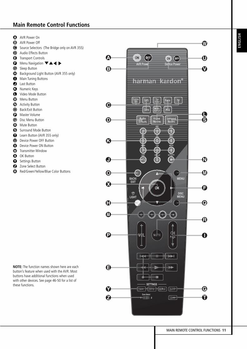
AVR Power OnAVR Power OffSource Selectors (The Bridge only on AVR 355)Audio Effects ButtonTransport ControlsMenu NavigationLKM NSleep ButtonBackground Light Button (AVR 355 only)Main Tuning ButtonsLast ButtonNumeric KeysVideo Mode ButtonMenu ButtonActivity ButtonBack/Exit ButtonMaster VolumeDisc Menu ButtonMute ButtonSurround Mode ButtonLearn Button (AVR 355 only)Device Power OFF ButtonDevice Power ON ButtonTransmitter WindowOK ButtonSettings ButtonZone Select ButtonRed/Green/Yellow/Blue Color Buttons
NOTE: The function names shown here are eachbutton’s feature when used with the AVR. Mostbuttons have additional functions when usedwith other devices. See page 46-50 for a list ofthese functions.
A
B
C
D
E
F
G
H
I
J
K
L
M
N
O
P
Q
R
S
T
U
V
W
X
Y
Z
a
ENGLI
SH
MAIN REMOTE CONTROL FUNCTIONS 11
12 MAIN REMOTE CONTROL FUNCTIONS
Main Remote Control Functions
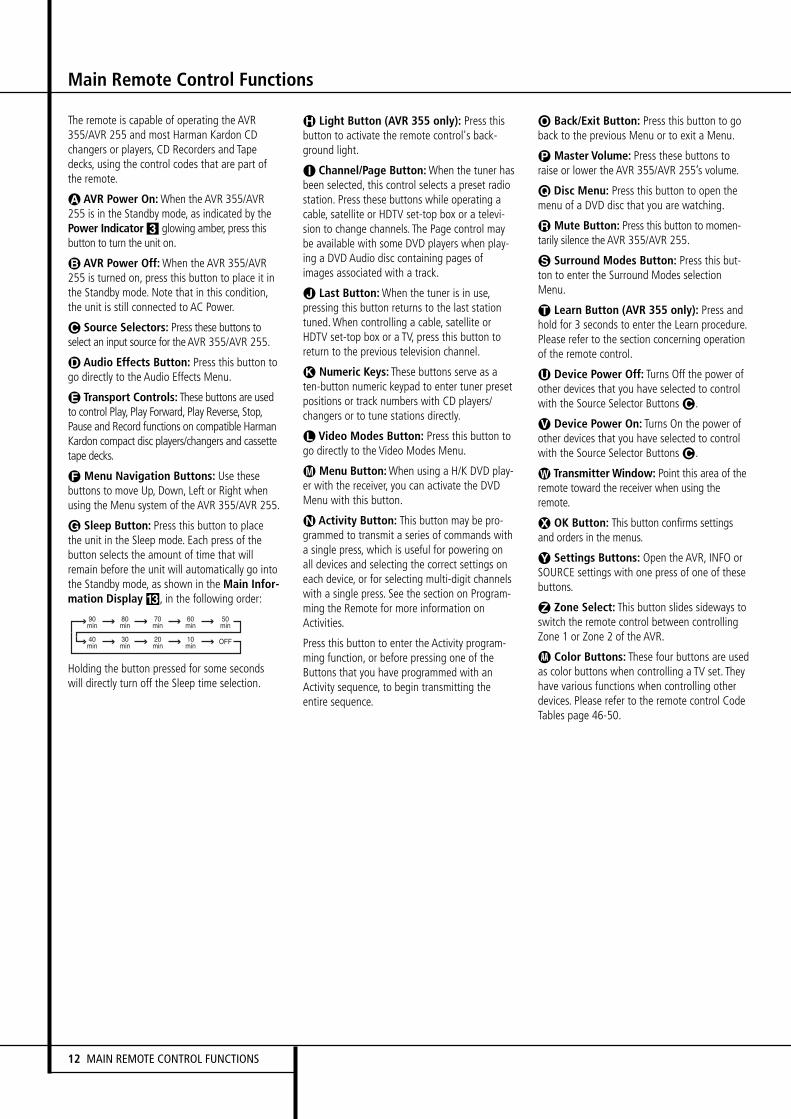
The remote is capable of operating the AVR355/AVR 255 and most Harman Kardon CDchangers or players, CD Recorders and Tapedecks, using the control codes that are part ofthe remote.
å AVR Power On:When the AVR 355/AVR255 is in the Standby mode, as indicated by thePower Indicator3 glowing amber, press thisbutton to turn the unit on.
∫ AVR Power Off:When the AVR 355/AVR255 is turned on, press this button to place it inthe Standby mode. Note that in this condition,the unit is still connected to AC Power.
ç Source Selectors: Press these buttons toselect an input source for theAVR 355/AVR 255.
∂ Audio Effects Button: Press this button togo directly to the Audio Effects Menu.
≠ Transport Controls: These buttons are usedto control Play, Play Forward, Play Reverse, Stop,Pause and Record functions on compatible HarmanKardon compact disc players/changers and cassettetape decks.
ƒ Menu Navigation Buttons: Use thesebuttons to move Up, Down, Left or Right whenusing the Menu system of the AVR 355/AVR 255.
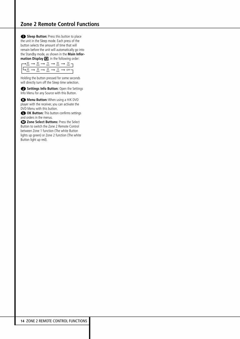
© Sleep Button: Press this button to placethe unit in the Sleep mode. Each press of thebutton selects the amount of time that willremain before the unit will automatically go intothe Standby mode, as shown in the Main Infor-mation Display #, in the following order:
Holding the button pressed for some secondswill directly turn off the Sleep time selection.
˙ Light Button (AVR 355 only): Press thisbutton to activate the remote control's back-ground light.
î Channel/Page Button:When the tuner hasbeen selected, this control selects a preset radiostation. Press these buttons while operating acable, satellite or HDTV set-top box or a televi-sion to change channels. The Page control maybe available with some DVD players when play-ing a DVD Audio disc containing pages ofimages associated with a track.
∆ Last Button:When the tuner is in use,pressing this button returns to the last stationtuned.When controlling a cable, satellite orHDTV set-top box or a TV, press this button toreturn to the previous television channel.
K Numeric Keys: These buttons serve as aten-button numeric keypad to enter tuner presetpositions or track numbers with CD players/changers or to tune stations directly.
¬ Video Modes Button: Press this button togo directly to the Video Modes Menu.
µ Menu Button:When using a H/K DVD play-er with the receiver, you can activate the DVDMenu with this button.
Ñ Activity Button: This button may be pro-grammed to transmit a series of commands witha single press, which is useful for powering onall devices and selecting the correct settings oneach device, or for selecting multi-digit channelswith a single press. See the section on Program-ming the Remote for more information onActivities.
Press this button to enter the Activity program-ming function, or before pressing one of theButtons that you have programmed with anActivity sequence, to begin transmitting theentire sequence.
ø Back/Exit Button: Press this button to goback to the previous Menu or to exit a Menu.
π Master Volume: Press these buttons toraise or lower the AVR 355/AVR 255’s volume.
œ Disc Menu: Press this button to open themenu of a DVD disc that you are watching.
® Mute Button: Press this button to momen-tarily silence the AVR 355/AVR 255.
ß Surround Modes Button: Press this but-ton to enter the Surround Modes selectionMenu.
† Learn Button (AVR 355 only): Press andhold for 3 seconds to enter the Learn procedure.Please refer to the section concerning operationof the remote control.
ü Device Power Off: Turns Off the power ofother devices that you have selected to controlwith the Source Selector Buttonsç.
√ Device Power On: Turns On the power ofother devices that you have selected to controlwith the Source Selector Buttonsç.
∑ Transmitter Window: Point this area of theremote toward the receiver when using theremote.
≈ OK Button: This button confirms settingsand orders in the menus.
¥ Settings Buttons: Open the AVR, INFO orSOURCE settings with one press of one of thesebuttons.
Ω Zone Select: This button slides sideways toswitch the remote control between controllingZone 1 or Zone 2 of the AVR.
a Color Buttons: These four buttons are usedas color buttons when controlling a TV set. Theyhave various functions when controlling otherdevices. Please refer to the remote control CodeTables page 46-50.
90min
80min
70min
60min
50min
40min
30min
20min
10min OFF
ZONE 2 REMOTE CONTROL FUNCTIONS 13
ENGLI
SH
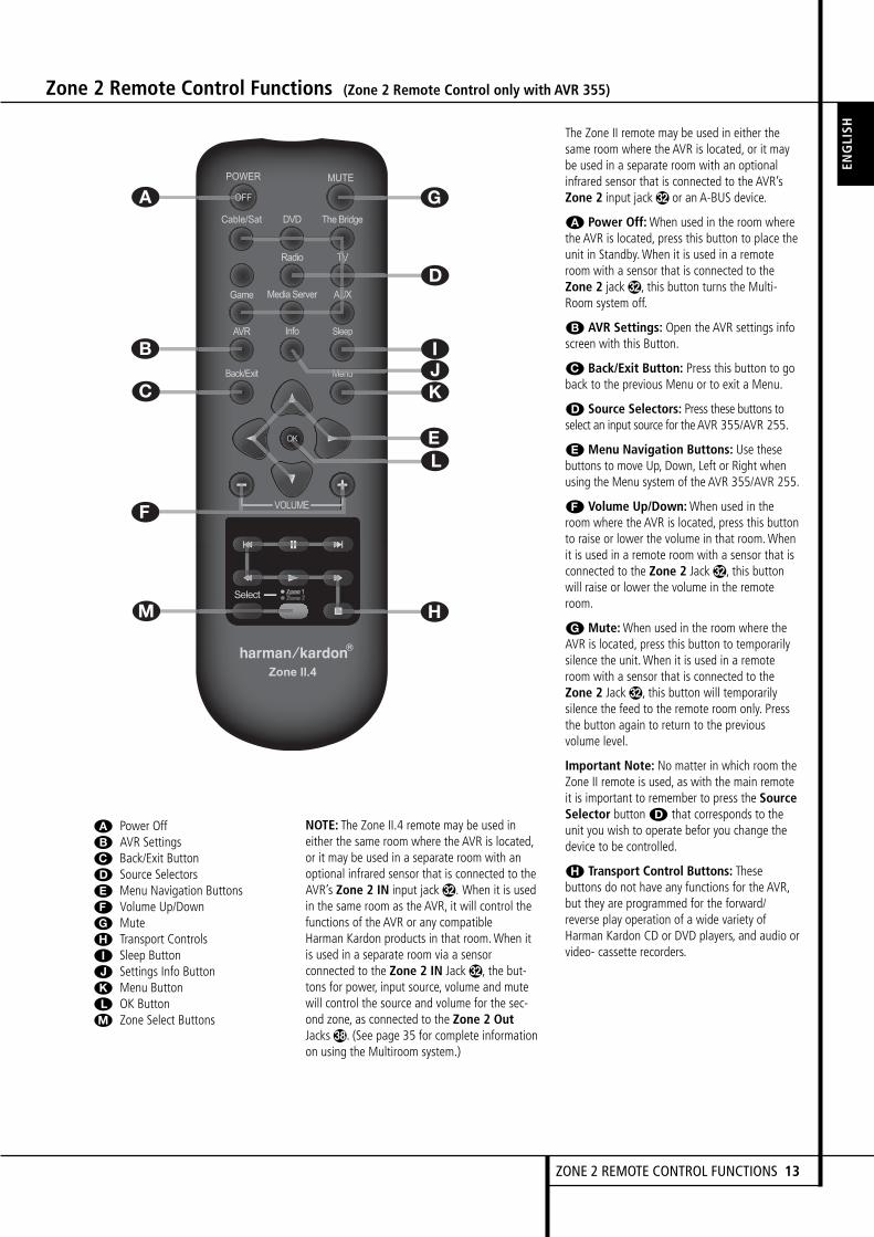
Zone 2 Remote Control Functions (Zone 2 Remote Control only with AVR 355)
A Power OffB AVR SettingsC Back/Exit ButtonD Source SelectorsE Menu Navigation ButtonsF Volume Up/DownG MuteH Transport ControlsI Sleep ButtonJ Settings Info ButtonK Menu ButtonL OK ButtonM Zone Select Buttons
NOTE: The Zone II.4 remote may be used ineither the same room where the AVR is located,or it may be used in a separate room with anoptional infrared sensor that is connected to theAVR’s Zone 2 IN input jack . When it is usedin the same room as the AVR, it will control thefunctions of the AVR or any compatibleHarman Kardon products in that room.When itis used in a separate room via a sensorconnected to the Zone 2 IN Jack , the but-tons for power, input source, volume and mutewill control the source and volume for the sec-ond zone, as connected to the Zone 2 OutJacks&. (See page 35 for complete informationon using the Multiroom system.)
The Zone II remote may be used in either thesame room where the AVR is located, or it maybe used in a separate room with an optionalinfrared sensor that is connected to the AVR’sZone 2 input jack or an A-BUS device.
A Power Off:When used in the room wherethe AVR is located, press this button to place theunit in Standby.When it is used in a remoteroom with a sensor that is connected to theZone 2 jack , this button turns the Multi-Room system off.
B AVR Settings: Open the AVR settings infoscreen with this Button.
C Back/Exit Button: Press this button to goback to the previous Menu or to exit a Menu.
D Source Selectors: Press these buttons toselect an input source for theAVR 355/AVR 255.
E Menu Navigation Buttons: Use thesebuttons to move Up, Down, Left or Right whenusing the Menu system of the AVR 355/AVR 255.
F Volume Up/Down:When used in theroom where the AVR is located, press this buttonto raise or lower the volume in that room.Whenit is used in a remote room with a sensor that isconnected to the Zone 2 Jack , this buttonwill raise or lower the volume in the remoteroom.
G Mute:When used in the room where theAVR is located, press this button to temporarilysilence the unit.When it is used in a remoteroom with a sensor that is connected to theZone 2 Jack , this button will temporarilysilence the feed to the remote room only. Pressthe button again to return to the previousvolume level.
Important Note: No matter in which room theZone II remote is used, as with the main remoteit is important to remember to press the SourceSelector buttonD that corresponds to theunit you wish to operate befor you change thedevice to be controlled.
H Transport Control Buttons: Thesebuttons do not have any functions for the AVR,but they are programmed for the forward/reverse play operation of a wide variety ofHarman Kardon CD or DVD players, and audio orvideo- cassette recorders.
A
B
C
D
E
F
H
G
IJK
L
M
Zone 2 Remote Control Functions
I Sleep Button: Press this button to placethe unit in the Sleep mode. Each press of thebutton selects the amount of time that willremain before the unit will automatically go intothe Standby mode, as shown in the Main Infor-mation Display #, in the following order:
Holding the button pressed for some secondswill directly turn off the Sleep time selection.
J Settings Info Button: Open the SettingsInfo Menu for any Source with this Button.
K Menu Button:When using a H/K DVDplayer with the receiver, you can activate theDVD Menu with this button.L OK Button: This button confirms settingsand orders in the menus.M Zone Select Buttons: Press the SelectButton to switch the Zone 2 Remote Controlbetween Zone 1 function (The white Buttonlights up green) or Zone 2 function (The whiteButton light up red).
90min
80min
70min
60min
50min
40min
30min
20min
10min OFF
14 ZONE 2 REMOTE CONTROL FUNCTIONS
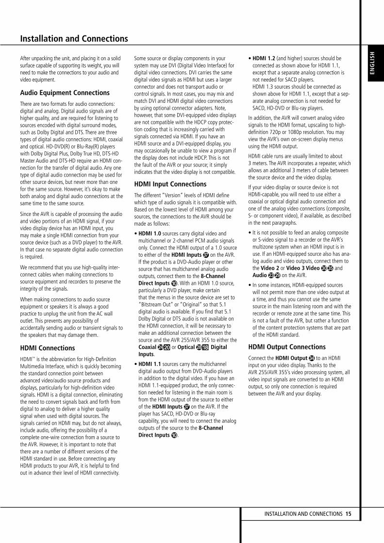
After unpacking the unit, and placing it on a solidsurface capable of supporting its weight, you willneed to make the connections to your audio andvideo equipment.
Audio Equipment Connections
There are two formats for audio connections:digital and analog. Digital audio signals are ofhigher quality, and are required for listening tosources encoded with digital surround modes,such as Dolby Digital and DTS. There are threetypes of digital audio connections: HDMI, coaxialand optical. HD-DVD(R) or Blu-Ray(R) playerswith Dolby Digital Plus, Dolby True HD, DTS-HDMaster Audio and DTS-HD require an HDMI con-nection for the transfer of digital audio. Any onetype of digital audio connection may be used forother source devices, but never more than onefor the same source. However, it’s okay to makeboth analog and digital audio connections at thesame time to the same source.
Since the AVR is capable of processing the audioand video portions of an HDMI signal, if yourvideo display device has an HDMI input, youmay make a single HDMI connection from yoursource device (such as a DVD player) to the AVR.In that case no separate digital audio connectionis required.
We recommend that you use high-quality inter-connect cables when making connections tosource equipment and recorders to preserve theintegrity of the signals.
When making connections to audio sourceequipment or speakers it is always a goodpractice to unplug the unit from the AC walloutlet. This prevents any possibility ofaccidentally sending audio or transient signals tothe speakers that may damage them.
HDMI Connections
HDMI™ is the abbreviation for High-DefinitionMultimedia Interface, which is quickly becomingthe standard connection point betweenadvanced video/audio source products anddisplays, particularly for high-definition videosignals. HDMI is a digital connection, eliminatingthe need to convert signals back and forth fromdigital to analog to deliver a higher qualitysignal when used with digital sources. Thesignals carried on HDMI may, but do not always,include audio, offering the possibility of acomplete one-wire connection from a source tothe AVR. However, it is important to note thatthere are a number of different versions of theHDMI standard in use. Before connecting anyHDMI products to your AVR, it is helpful to findout in advance their level of HDMI connectivity.
Some source or display components in yoursystem may use DVI (Digital Video Interface) fordigital video connections. DVI carries the samedigital video signals as HDMI but uses a largerconnector and does not transport audio orcontrol signals. In most cases, you may mix andmatch DVI and HDMI digital video connectionsby using optional connector adapters. Note,however, that some DVI-equipped video displaysare not compatible with the HDCP copy protec-tion coding that is increasingly carried withsignals connected via HDMI. If you have anHDMI source and a DVI-equipped display, youmay occasionally be unable to view a program ifthe display does not include HDCP. This is notthe fault of the AVR or your source; it simplyindicates that the video display is not compatible.
HDMI Input Connections
The different “Version” levels of HDMI definewhich type of audio signals it is compatible with.Based on the lowest level of HDMI among yoursources, the connections to the AVR should bemade as follows:
• HDMI 1.0 sources carry digital video andmultichannel or 2-channel PCM audio signalsonly. Connect the HDMI output of a 1.0 sourceto either of the HDMI Inputs% on the AVR.If the product is a DVD-Audio player or othersource that has multichannel analog audiooutputs, connect them to the 8-ChannelDirect Inputs.With an HDMI 1.0 source,particularly a DVD player, make certainthat the menus in the source device are set to“Bitstream Out” or “Original” so that 5.1digital audio is available. If you find that 5.1Dolby Digital or DTS audio is not available onthe HDMI connection, it will be necessary tomake an additional connection between thesource and the AVR 255/AVR 355 to either theCoaxialÓ or Optical* DigitalInputs.
• HDMI 1.1 sources carry the multichanneldigital audio output from DVD-Audio playersin addition to the digital video. If you have anHDMI 1.1-equipped product, the only connec-tion needed for listening in the main room isfrom the HDMI output of the source to eitherof the HDMI Inputs% on the AVR. If theplayer has SACD, HD-DVD or Blu-raycapability, you will need to connect the analogoutputs of the source to the 8-ChannelDirect Inputs.
• HDMI 1.2 (and higher) sources should beconnected as shown above for HDMI 1.1,except that a separate analog connection isnot needed for SACD players.HDMI 1.3 sources should be connected asshown above for HDMI 1.1, except that a sep-arate analog connection is not needed forSACD, HD-DVD or Blu-ray players.
In addition, the AVR will convert analog videosignals to the HDMI format, upscaling to high-definition 720p or 1080p resolution. You mayview the AVR’s own on-screen display menususing the HDMI output.
HDMI cable runs are usually limited to about3 meters. The AVR incorporates a repeater, whichallows an additional 3 meters of cable betweenthe source device and the video display.
If your video display or source device is notHDMI-capable, you will need to use either acoaxial or optical digital audio connection andone of the analog video connections (composite,S- or component video), if available, as describedin the next paragraphs.
• It is not possible to feed an analog compositeor S-video signal to a recorder or the AVR’smultizone system when an HDMI input is inuse. If an HDMI-equipped source also has ana-log audio and video outputs, connect them tothe Video 2 or Video 3 Video" andAudio on the AVR.
• In some instances, HDMI-equipped sourceswill not permit more than one video output ata time, and thus you cannot use the samesource in the main listening room and with therecorder or remote zone at the same time. Thisis not a fault of the AVR, but rather a functionof the content protection systems that are partof the HDMI standard.
HDMI Output Connections
Connect the HDMI Output# to an HDMIinput on your video display. Thanks to theAVR 255/AVR 355’s video processing system, allvideo input signals are converted to an HDMIoutput, so only one connection is requiredbetween the AVR and your display.
Installation and Connections
ENGLI
SH
INSTALLATION AND CONNECTIONS 15

Referring to drawing of the remote control onpage 11,there is a section of 7 buttons markedC, (AVR 355: 8 Buttons) near the top of theremote designated “Source Selectors”:Cable/Sat, DVD, Media Server, Radio, TV, Gameand AUX. Each of these buttons corresponds toa “source input”. The AVR’s flexible designallows you to use almost any combination ofaudio and video connections for each sourcedevice. The goal of the installation is to matchup each of your source devices, e.g., DVD playerand cable television box, with the correct con-nectors on the AVR.
You may connect a source device to any appro-priate input connectors.Note which audio andvideo inputs are used for each device in Table A5in the appendix. Table A1 indicates the defaultinput-connection assignments, any of which maybe changed to match the actual connections inyour system.
The precise connections to be made depend onthe capabilities of the source device and yourvideo display (TV). Select the best audio andvideo connections for each source.
Analog and Digital Input Connections1. Connect the analog output of a CD player toany of the analog audio inputs.
NOTE:When the CD player has both fixed andvariable audio outputs it is best to use the fixedoutput unless you find that the input to thereceiver is so low that the sound is noisy, or sohigh that the signal is distorted.
2. Connect the analog Play/Out jacks of a cas-sette deck, MD, CD-R or other audio recorder tothe analog audio input jacks . Connect theanalog Record/In jacks on the recorder to theaudio output jacks on the AVR.
3. Connect the digital output of any digitalsources such as a CD or DVD changer or player,advanced video game, a digital satellite receiver,HDTV tuner or digital cable set-top box or theoutput of a compatible computer sound card tothe Optical and Coaxial Digital Inputs*&.We recommend connecting the coaxial digitalaudio output of your DVD player to the Coax 1Digital Audio Input, since that digital inputis assigned to the DVD source by default.
If your DVD player has HDMI connection, useHDMI connection instead.
Although there is no official source on the AVRnamed CD, Phono or Audio, you may assign theaudio device to an available source, such as TV(if the Cable/Sat source is in use for broadcasttelevision), Game or AUX.
You can then add the name of the unit to thename of the assigned input, to make it read forexample: "AUX - CD". (Please note that the AVRdoes not have a Phono input with RIAA fordirect hook-up to a record player. You must use aseparate RIAA preamplifier between a recordplayer and the AVR)
NOTE: If you wish for your digital source deviceto be available for use by the multiroom system,you will need to connect its analog audiooutputs to the appropriate inputs on theAVR 255/AVR 355, as the multiroom system isnot capable of distributing digital signals to theremote zone.
4. Connect the Coaxial or Optical DigitalOutputs on the rear panel of the AVR to thematching digital input connections on a CD-R orMiniDisc recorder.
5. Assemble the AM Loop Antenna supplied withthe unit as shown below. Connect it to the AMand GND screw terminals.
6. Connect the supplied FM antenna to the FM(75 ohm) connection. The FM antenna maybe an external roof antenna, an inside poweredor wire lead antenna or a connection from acable system. Note that if the antenna orconnection uses 300-ohm twin-lead cable, youshould use a 300-ohm-to-75-ohm adapter tomake the connection.
7.With the AVR 355 turned off, connect theoptional Harman Kardon toDigital Media Player (DMP) Connector.Your compatible Apple® iPod® may be docked in
when you wish to use it as your audiosource device. This function is available on theAVR 355 only. The AVR 255 features a STEREOJACK Input instead to which all sorts of portabledevices can be connected via the headphoneoutput of such device.
8. Connect the front, center and surroundspeaker outputs to the respectivespeakers.
To assure that all the audio signals are carried toyour speakers without loss of clarity orresolution, we suggest that you use high-qualityspeaker cable. Many brands of cable areavailable and the choice of cable may beinfluenced by the distance between yourspeakers and the receiver, the type of speakersyou use, personal preferences and other factors.Your dealer or installer is a valuable resource toconsult in selecting the proper cable.
Regardless of the brand of cable selected, werecommend that you use a cable constructed offine, multistrand copper with a cross-sectiongreater than 2 mm2.
Cable with a cross-section of 1.5 mm2 may beused for short runs of less than 4 m.We do notrecommend that you use cables with a cross-sec-tion less than 1 mm2 due to the power loss anddegradation in performance that will occur.
Cables that are run inside walls should have theappropriate markings to indicate listing with anyappropriate testing agency standards. Questionsabout running cables inside walls should bereferred to your installer or a licensed electricianwho is familiar with the applicable local buildingcodes in your area.
When connecting wires to the speakers, be cer-tain to observe proper polarity. Note that thepositive (+) terminal of each speaker connectionnow carries a specific color code as noted onpage 8. However, most speakers will still use ared terminal for the postive (+) connection.Connect the “negative” or “black” wire to thesame terminal on both the receiver and thespeaker.
NOTE:While most speaker manufacturersadhere to an industry convention of using blackterminals for negative and red ones for positive,some manufacturers may vary from thisconfiguration. To assure proper phase andoptimal performance, consult the identificationplate on your speaker or the speaker’s manual toverify polarity. If you do not know the polarity ofyour speaker, ask your dealer for advice beforeproceeding, or consult the speaker’smanufacturer.
We also recommend that the length of cableused to connect speaker pairs be identical. Forexample, use the same length piece of cable toconnect the front-left and front-right orsurround-left and surround-right speakers,even if the speakers are a different distancefrom the AVR.
Installation and Connections
16 INSTALLATION AND CONNECTIONS
Installation and Connections
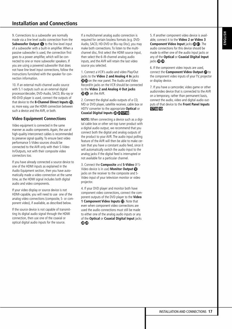
9. Connections to a subwoofer are normallymade via a line level audio connection from theSubwoofer Output to the line-level inputof a subwoofer with a built-in amplifier.When apassive subwoofer is used, the connection firstgoes to a power amplifier, which will be con-nected to one or more subwoofer speakers. Ifyou are using a powered subwoofer that doesnot have line-level input connections, follow theinstructions furnished with the speaker for con-nection information.
10. If an external multi-channel audio sourcewith 5.1 outputs such as an external digitalprocessor/decoder, DVD-Audio, SACD, Blu-ray orHD-DVD player is used, connect the outputs ofthat device to the 8-Channel Direct Inputs,or, more easy, use the HDMI connection betweensuch a device and the AVR, or both.
Video Equipment Connections
Video equipment is connected in the samemanner as audio components. Again, the use ofhigh-quality interconnect cables is recommendedto preserve signal quality. To ensure best videoperformance S-Video sources should beconnected to the AVR only with their S-VideoIn/Outputs, not with their composite videoconnectors too.
If you have already connected a source device toone of the HDMI inputs as explained in theAudio Equipment section, then you have auto-matically made a video connection at the sametime, as the HDMI signal includes both digitalaudio and video components.
If your video display or source device is notHDMI-capable, you will need to use one of theanalog video connections (composite, S- or com-ponent video), if available, as described below.
If the source device is not capable of transmit-ting its digital audio signal through the HDMIconnection, then use one of the coaxial oroptical digital audio inputs for the source.
If a multichannel analog audio connection isrequired for certain lossless formats (e.g. DVD-Audio, SACD, HD-DVD or Blu-ray Disc), you maymake both connections. To listen to the multi-channel disc, first select the HDMI source input,then select the 6-/8-channel analog audioinputs, and the AVR will retain the last videosource you selected.
1. Connect a VCR’s audio and video Play/Outjacks to the Video 2 and Analog 4 In jacks on the rear panel. The Audio and VideoRecord/In jacks on the VCR should be connectedto the Video 2 and Analog 4 Out jacks on the AVR.
2. Connect the digital audio outputs of a CD,MD or DVD player, satellite receiver, cable box orHDTV converter to the appropriate Optical orCoaxial Digital Inputs&* .
NOTE:When connecting a device such as a digi-tal cable box or other set-top tuner product witha digital audio output, we recommend that youconnect both the digital and analog outputs ofthe product to your AVR. The audio input pollingfeature of the AVR will then be able to make cer-tain that you have a constant audio feed, since itwill automatically switch the audio input to theanalog jacks if the digital feed is interrupted ornot available for a particular channel.
3. Connect the Composite and S-Video (if S-Video device is in use) Monitor Outputjacks on the receiver to the composite and S-Video input of your television monitor or videoprojector.
4. If your DVD player and monitor both havecomponent video connections, connect the com-ponent outputs of the DVD player to the Video1 Component Video Inputs. Note thateven when component video connections areused the audio connections must still be madeto either one of the analog audio inputs or anyof the Optical or Coaxial Digital Input jacks.
5. If another component video device is avail-able, connect it to the Video 2 or Video 3Component Video Input jacks,) . Theaudio connections for this device should bemade to either one of the audio input jacks orany of the Optical or Coaxial Digital Inputjacks.
6. If the component video inputs are used,connect the Component Video Output tothe component video inputs of your TV, projectoror display device.
7. If you have a camcorder, video game or otheraudio/video device that is connected to the AVRon a temporary, rather than permanent basis,connect the audio, video and digital audio out-puts of that device to the Front Panel Inputs&*(.
ENGLI
SH
INSTALLATION AND CONNECTIONS 17
Installation and Connections
System and Power ConnectionsThe AVR is designed for flexible use with multi-room systems, external control components andpower amplifiers.
Main Room Remote Control ExtensionIf the receiver is placed behind a solid or smokedglass cabinet door, the obstruction may preventthe remote sensor from receiving commands. Inthis event, the remote sensor of anyHarman Kardon or other compatible device, notcovered by the door, or an optional remotesensor may be used. Connect the Remote IROutput of that device or the output of theremote sensor to the Remote IR Input jack.
If other components are also prevented fromreceiving remote commands, only one sensor isneeded. Simply use this unit’s sensor or a remoteeye by running a connection from the RemoteIR Output jack to the Remote IR Inputjack on Harman Kardon or other compatibleequipment.
Zone II IR Link(Limited options on AVR 255)The key to remote room operation is to link theremote room to the AVR’s location with wire foran infrared receiver and speakers or an amplifier.The remote room IR receiver (this can be anoptional IR receiver or any other remotableHarman Kardon device in the remote room withIR sensor integrated) should be connected to theAVR via standard coaxial cable. Connect theRemote IR Output of the device or of theoptional sensor with the Zone II IR Input jack on the AVR’s rear panel.
If other Harman Kardon compatible sourceequipment is part of the main room installation,the Remote IR Output jack on the rearpanel should be connected to the IR IN jack onthat source device. This will enable the remoteroom location to control source equipmentfunctions.
When a remote IR sensor is used to control non-Harman Kardon source equipment, we recom-mend that you make a direct connection or usean optional, external IR “blaster” connected tothe Remote IR Carrier Output Jack(. If youare in doubt as to which IR Output jack to usefor the equipment in your system, contact yourdealer or installer, or the manufacturer’s supportsite and ask whether the unit to be controlleduses “full carrier” or “stripped” carrier IRcommands.When “full carrier commands” areused, make the connection to the Remote IRCarrier Output Jack(. Otherwise, make theconnection to the Remote IR Output Jackas noted above (IR Carrier Output available onAVR 355 only).
NOTE: All remotely controlled components mustbe linked together in a “daisy chain”. Connectthe IR OUT jack of one unit to the IR IN of thenext to establish this chain.
Multiroom Audio ConnectionsDepending on your system`s requirement anddistance from the AVR to the remote room, threeoptions are available for audio connection:
Option 1 (on AVR 355): Use high-quality,shielded audio interconnect phono cable fromthe AVR’s location to the remote room. In theremote room, connect the interconnect cable toa stereo power amplifier. The amplifier will beconnected to the room’s speakers. At the AVR,plug the audio interconnect cables into theZone 2 Out Jacks& on the AVR’s rear panel.
Option 2 (on AVR 355): Place the amplifierthat will provide power to the remote locationspeakers in the same room as the AVR, and con-nect the Zone 2 Out jacks& on the rear panelof the AVR to the audio input of the remote roomamplifier. Use the appropriate speaker wire to con-nect the optional power amplifier to the remotespeakers. High-quality wire of at least 2.5 mm2 isrecommended for long multiroom connections.
Option 3 (on AVR 255 and AVR 355): Takingadvantage of the AVR’s built-in seven-channelamplifier, it is possible to use two of the amplifi-er channels to power speakers in the remoteroom.When using this option you will not beable to use the full 7.1-channel capabilities ofthe AVR in the main listening room, but you willbe able to add another listening room withoutadditional external power amplifiers. To use theinternal amplifiers to power a remote zone, con-nect the speakers for the remote room locationto the Surround Back/Multiroom SpeakerOutputs. Before using the remote room youwill need to configure the amplifiers for sur-round operation by changing a setting in theMultiroom menu, following the instructionsshown on page 18.
NOTE: For all options, you may connect anoptional IR sensor (Harman Kardon He 1000) inthe remote room to the AVR via an appropriatecable. Connect the sensor’s cable to the Zone 2IR Input on the AVR and use the Zone IIremote to control the room volume.Alternatively, you may install an optional volumecontrol between the output of the amplifiers andthe speakers.
NOTE: The AVR 355’s multiroom system is onlycapable of distributing analog audio sources tothe remote zone. Therefore, when connectingyour digital audio equipment (e.g. CD or DVDplayers) as described on page 18, make sure touse both analog and digital audio connectionsto ensure that the devices will be available tothe multiroom system.
A-BUS Installation Connections(AVR 355 only)The AVR is among the very few receivers avail-able today that offers built-in A-BUS Ready®
operation.When used with an optional A-BUSkeypad or control module, you have all thebenefits of remote zone operation without theneed for an external power amplifier.
To use the AVR with an approved A-BUS prod-uct, simply connect the keypad or module that isin the remote room to the AVR using standard“Category 5” wiring that is properly rated forthe inwall use specific to the installation.Terminate the wiring at the receiver end to astandard RJ-45 jack in compliance with theinstructions furnished with the A-BUS module.
You may connect a single A-BUS module to theAVR 355 with no further equipment needed. Ifyou wish to connect more than one A-BUSmodule, an optional, external A-BUS hub may beused to provide that capability.
No further installation or adjustment is needed,as the A-BUS connector on the AVR routes thesignals in and out of the keypad to their properdestination for power, signal source and control.The output fed to the A-BUS jack is determinedby the AVR’s multiroom system, and the menusmay be used as is.
AC Power ConnectionsThis unit is equipped with one accessory ACoutlet. It may be used to power accessorydevices, but should not be used with high-currentdraw equipment such as power amplifiers. Thetotal power draw to the Switched Outletshould not exceed 50 watts.
The Switched outlet will receive power onlywhen the unit is on completely. This is recom-mended for devices that have no power switchor a mechanical power switch that may be left inthe “ON” position.
NOTE: Many audio and video products go intoStandby mode when they are used withswitched outlets, and cannot be fully turned onusing the outlet alone without a remote controlcommand.
The AVR draws significantly more current thanother household devices such as computers thatuse removable power cords. For that reason, it isimportant that only the cord supplied with theAVR 355 (AVR 255 has a fixed power cord) or adirect replacement of identical capacity be used.
Once the power cord is connected, you arealmost ready to enjoy the AVR 255/AVR 355’sincredible power and fidelity!
18 INSTALLATION AND CONNECTIONS

ENGLI
SH
INSTALLATION AND CONNECTIONS 19
Installation and Connections
Speaker Selection
No matter which type or brand of speakers isused, the same model or brand of speakershould be used for the front-left, center andfront-right speakers. This creates a seamlessfront soundstage and eliminates the possibilityof distracting sonic disturbances that occur whena sound moves across mismatched front-channelspeakers.
Speaker Placement
The placement of speakers in a multichannelhome-theater system can have a noticeableimpact on the quality of sound reproduced.
Depending on the type of center-channelspeaker in use and your viewing device, placethe center speaker either directly above or belowyour TV, or in the center behind a perforatedfront-projection screen.
Once the center-channel speaker is installed,position the left-front and right-front speakers sothat they are as far away from one another asthe center-channel speaker is from the preferredlistening position. Ideally, the front-channelspeakers should be placed so that their tweetersare no more than 60 cm above or below thetweeter in the center-channel speaker.
They should also be at least 0.5 meter from yourTV set unless the speakers are magneticallyshielded to avoid colourings on the TV screen.Note that most speakers are not shielded, evenwith complete surround sets only the Centerspeaker may be.
Depending on the specifics of your roomacoustics and the type of speakers in use, youmay find that imaging is improved by moving thefront-left and front-right speakers slightlyforward of the center-channel speaker. Ifpossible, adjust all front loudspeakers so thatthey are aimed at ear height when you areseated in the listening position.
Using these guidelines, you’ll find that it takessome experimentation to find the correctlocation for the front speakers in your particularinstallation. Don’t be afraid to move thingsaround until the system sounds correct. Optimizeyour speakers so that audio transitions acrossthe front of the room sound smooth.
When the AVR is used in 5.1-channel operation,the preferred location for surround speakers ison the side walls of the room, at or slightlybehind the listening position. In a 6.1-channelsystem, a back surround speaker is required, ide-ally placed at the center of the room's rear wall,pointing directly towards the front center chan-nel speaker. The center of the speaker shouldface you (see below).
In a 7.1-channel system, both side surround andback surround speakers are required. The centerof the speaker should face you (see below).
Rear surround speakers are required when a full7.1-channel system is installed, and they mayalso be used in 5.1 channel mode as an alterna-tive mounting position when it is not practical toplace the main surround speakers at the sides ofthe room. Speakers may be placed on a rearwall, behind the listening position. As with theside speakers, the center of the rear surroundsshould face you. The speakers should be no morethan 2 meters behind the rear of the seatingarea.
It is appropriate to configure the AVR 255/AVR 355 for either 5.1- or 7.1-channel opera-tion, but not for 6.1 channels.When 6.1-channelprogram material or a 6.1-channel processingmode is in use, material for the surround backchannel will be outputted simultaneouslythrough both the Surround Back Left andRight Speaker Outputs. Connecting onlyone loudspeaker to these speaker terminals willnot only deprive you of the benefits of 7.1-chan-nel surround modes, such as Logic 7, but willalso interfere with the functioning of EzSet/EQspeaker setup and calibration, as described onpage 22. It may also put undesirable strain onthe surround back amplifier circuits and powersupplies.
A) Front Channel Speaker Installation withDirect-View TV Sets or Rear-Screen Projectors.
At least 15 cm from celling
At least 60 cm
5.1-Channel System
6.1-Channel System
7.1-Channel System
Center Front Speaker
No morethan 24"
Front RightSpeaker
Front LeftSpeaker
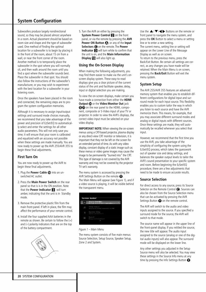
20 SYSTEM CONFIGURATION
System Configuration
Subwoofers produce largely nondirectionalsound, so they may be placed almost anywherein a room. Actual placement should be based onroom size and shape and the type of subwooferused. One method of finding the optimallocation for a subwoofer is to begin by placing itin the front of the room, about 15 cm from awall, or near the front corner of the room.Another method is to temporarily place thesubwoofer in the spot where you will normallysit, and then walk around the room until youfind a spot where the subwoofer sounds best.Place the subwoofer in that spot. You shouldalso follow the instructions of the subwoofer’smanufacturer, or you may wish to experimentwith the best location for a subwoofer in yourlistening room.
Once the speakers have been placed in the roomand connected, the remaining steps are to pro-gram the system configuration memories.
Although it is necessary to assign input/outputsettings and surround mode choices manually,we recommend that you take advantage of thepower and precision of EzSet/EQ to automatical-ly select and enter the settings for all otheraudio parameters. This will not only save youtime; it will ensure that your room is calibratedand equalized with an accuracy not possiblewhen these settings are made manually. You arenow ready to power up the AVR 255/AVR 355 tobegin these final adjustments.
First Turn On
You are now ready to power up the AVR tobegin these final adjustments.
1. Plug the Power Cable into an un-switched AC outlet.
2. Press the Main Power Switch on the rearpanel so that is is in the ON position. Notethat the Power Indicator 3 will turnamber, indicating that the unit is in Standbymode.
3. Remove the protective plastic film from themain front-panel. If left in place, the film mayaffect the performance of your remote control.
4. Install the four supplied AAA batteries in theremote as shown. Be certain to follow the (+)and (–) polarity indicators that are on the topof the battery compartment.
5. Turn the AVR on either by pressing theSystem Power Control 2 on the frontpanel, or via the remote by pressing the AVRPower ON Button A, or any of the InputSelectors C on the remote. The PowerIndicator 3 will turn white to confirm thatthe unit is on, and the Main InformationDisplay # will also light up.
Using the On-Screen Display
When making the following adjustments, youmay find them easier to make via the unit’s on-screen display system. These easy-to-readdisplays give you a clear picture of the currentstatus of the unit and facilitate speaker, delay,input or digital selection you are making.
To view the on-screen displays, make certain youhave made a connection from either the HDMIOutput# or the VideoMonitor Out jack on the rear panel to the HDMI, compo-nent, composite or S-Video input of your TV orprojector. In order to view the AVR’s displays, thecorrect video input must be selected on yourvideo display.
IMPORTANT NOTE:When viewing the on-screenmenus using a CRT-based projector, plasma displayor any direct-view CRT monitor or television, it isimportant that they not be left on the screen foran extended period of time.As with any videodisplay, constant display of a static image such asthese menus or video game images may cause theimage to be permanently “burned into” the CRT.This type of damage is not covered by the AVRwarranty and may not be covered by the projectorTV set’s warranty.
The menu system is accessed by pressing theAVR Settings Button on the remoteY.The Main Menu will appear (see Figure 1), and ifa video source is playing, it will be visible behindthe transparent menu.
Figure 1 – Main Menu
The menu system consists of five main menus:Source Selection, Setup Source, Speaker Setup,Zone 2 and System.
Use theK/L/M/N Buttons on the remote orfront panel to navigate the menu system, andpress the OK Button to select a menu or settingline or to enter a new setting.The current menu, setting line or setting willappear on the Lower Line of the MessageDisplay as well as on screen.To return to the previous menu, press theBack/Exit Button. Be certain all settings are cor-rect, as any changes you have made will beretained.When the Main Menu is on screen,pressing the Back/Exit Button will exit themenu system.
System Setup
The AVR 255/AVR 355 features an advancedmemory system that enables you to establish dif-ferent configurations for digital input and sur-round mode for each input source. This flexibilityenables you to custom tailor the way in whichyou listen to each source and have the AVRmemorize them. This means, for example, thatyou may associate different surround modes andanalog or digital inputs with different sources.Once these settings are made, they will auto-matically be recalled whenever you select thatinput.
However, we recommend that the first time youuse the AVR, you take advantage of thesimplicity of configuring the system using theEzSet/EQ process, which takes the guessworkout of speaker size and delay settings, andbalances the speaker output levels to tailor theAVR’s sound presentation to your specific systemand room. Before beginning the EzSet/EQprocedure, there are a few adjustments thatneed to be made to ensure accurate results.
Source Selection
For direct access to any source, press its SourceSelector on the Remote ControlC. Sources canalso be chosen from the Source Selection menuthat can be activated by pressing the AVRSettings ButtonY on the remote control.
The AVR will switch to the audio and videoinputs assigned to the source. If you specified asurround mode for the source, the AVR willswitch to that mode.
The source name will appear in the upper line ofthe front-panel display. If you retitled the source,the new title will appear. The audio inputassigned to the source (analog or one of the dig-ital audio inputs) will also appear. The surroundmode will be displayed on the lower line.
Any other settings you adjusted in the SetupSource menu will also be selected. You may viewthese settings in the Source Info menu at anytime by pressing the Info Settings ButtonY.

System Configuration
ENGLI
SH
SYSTEM CONFIGURATION 21
Audio and Video Input Selection
Please see Table A1 in the appendix for the fac-tory default input assignments for each source.You may assign any available input to anysource using the Source Info menu, accessibleeither by pressing the AVR Settings ButtonYand selecting the Setup Source line, or by press-ing the Info Settings ButtonY for direct access.
When a source is selected, the AVR will checkthe assigned digital audio input for a signal. Ifone is present, the digital input will be selected.If not, the AVR will select the analog audio inputspecified at the Audio Auto Polling line of theSetup Source menu. If you don’t want the AVRto select an analog audio input for the source,change this setting to Off.
The AVR will also select the assigned videosource. There are no “Audio Only” sources onthe AVR, other than the Radio, which uses a spe-cial on-screen menu. If no video signal is pres-ent, the display will remain black. You may pairan audio device with an A/V device’s video sig-nal using the Source Info menu as explained inthe Initial Setup section. Sources may shareaudio or video inputs to suit your application.
Set Up Sources
The Source Info menu is used to assign thecorrect physical audio and video connections toeach source. It also provides access to a varietyof other settings, many of which may beadjusted later as you become more familiar withthe AVR.
The following settings are not optional and mustbe adjusted now to enable playback of eachsource: Video Input from source, Audio Inputfrom Source and Resolution to Display.
The other settings may be adjusted at any timeto improve performance.
To display the Source Info menu, press the InfoSettings Button (front panel 7 or remoteY). Ascreen similar to the one shown in Figure 2 willappear. This screen may also be accessed fromthe Main Menu by selecting the Setup Sourceline and selecting a source from the slide-inmenu.
Figure 2 – Setup Source Menu
Audio Effects: Select this line to display theAudio Effects submenu, where you may: adjustthe bass and treble tone controls; adjust the LFEtrim; activate the saved EzSet/EQ settings oradjust the night mode setting. It isrecommended that you leave this submenu at itsdefault settings, and return to it later if yoursystem requires any fine-tuning.See the Advanced Functions section for moreinformation.
Video Modes: Select this line to display theVideo Modes submenu, where you select frompreprogrammed or custom picture settings andmake picture adjustments. It is recommendedthat you leave the settings at their factorydefaults. Picture adjustments should be made toyour video display first, with this menu used onlyfor fine-tuning.See the Advanced Functions section for moreinformation.
Surround Mode: Select this line to display theSurround Mode submenu, where you mayprogram the desired surround mode for varioustypes of analog programs, including movies,music and games. You may also specify a specificstereo mode (depending on the number ofchannels desired) and a virtual surround mode ifyour system uses fewer than the fullcomplement of seven main speakers (plus asubwoofer).
Digital surround signals, such as Dolby Digitaland DTS programs, are automatically played intheir native formats, although you may changethe surround mode at any time.See the Advanced Functions section forinformation on surround modes available withdigital programs.
In the factory default Auto Select mode, the AVRwill analyze the source signal and select theoptimum playback mode. At the factory the AVRwas programmed to use Logic 7 Movie mode foroptimal playback of movies, including televisionprograms; Logic 7 Music mode for musicrecordings, such as CDs; and Logic 7 Gamemode when a video game console is in use.
Audio Format From Source: This line isinformational only.When a digital program isplaying, its format will be identified here.Whenanalog audio programs are playing, this lineindicates NO AUDIO INPUT, referring to digitalinputs only.
Video Input from source: Select this line toassign the correct video input to the source.Refer back to Table A5 in the appendix, whereyou noted the physical video input the source isconnected to, and select the input here.
Audio Input from source: Select this line toassign the correct analog or digital audio inputto the source. Refer back to Table A5 in theappendix, where you noted the physical audioinput the source is connected to, and select theinput here. If both analog and digital audioconnections were made, select the digital inputhere, and select the analog input at the AudioAuto Polling line below.
NOTE: For sources connected to an HDMI Input,the Video and Audio Input settings shouldindicate the same HDMI connection.
Resolution to Display: This line reflects thevideo output resolution, which is dependentupon the capabilities of the video display.
NOTE: When using the AVR’s on-screen menusystem, we recommend selecting a video outputresolution of 720p or higher for best legibility,and to provide graphics that simplify someconfiguration options. Depending on theresolution selected, the menus shown by yoursystem may vary in appearance.
• If the display is connected to the AVR’sComposite or S-Video Monitor Output, the videooutput resolution must be manually set to 576ito view any content, including the AVR’s ownmenus. The AVR's default resolution is set to576i.
Since there is no picture if the resolution is sethigher than the display’s capability, or if theHDMI system does not automatically select thebest resolution, in these cases you must adjustthe resolution by pressing the front-panelResolution Button followed by the Up/DownButtons 3 until the correct setting appears onthe Lower Line of the front-panel MessageDisplay and confirm with the OK Button 5. TheDisplay now shows CANCEL, and you must scrollto have the Display show ACCEPT with theUp/Down Buttons 3 and then press OK tomake the new Resolution take effect. If youpress OK when CANCEL is on the screen, or ifyou do nothing, the Resolution remains as it wasbefore. For composite and S-video, the correctsetting is 576i. For component video, it is thehighest resolution where a picture is visible.
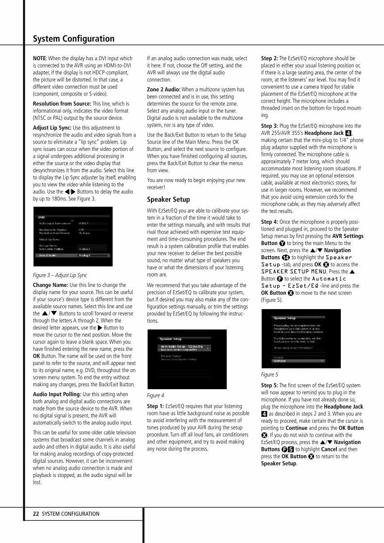
NOTE:When the display has a DVI input whichis connected to the AVR using an HDMI-to-DVIadapter, if the display is not HDCP-compliant,the picture will be distorted. In that case, adifferent video connection must be used(component, composite or S-video).
Resolution from Source: This line, which isinformational only, indicates the video format(NTSC or PAL) output by the source device.
Adjust Lip Sync: Use this adjustment toresynchronize the audio and video signals from asource to eliminate a “lip sync” problem. Lipsync issues can occur when the video portion ofa signal undergoes additional processing ineither the source or the video display thatdesynchronizes it from the audio. Select this lineto display the Lip Sync adjuster by itself, enablingyou to view the video while listening to theaudio. Use theM/N Buttons to delay the audioby up to 180ms. See Figure 3.
Figure 3 – Adjust Lip Sync
Change Name: Use this line to change thedisplay name for your source. This can be usefulif your source’s device type is different from theavailable source names. Select this line and usetheK/L Buttons to scroll forward or reversethrough the letters A through Z.When thedesired letter appears, use theN Button tomove the cursor to the next position. Move thecursor again to leave a blank space.When youhave finished entering the new name, press theOK Button. The name will be used on the frontpanel to refer to the source, and will appear nextto its original name, e.g. DVD, throughout the onscreen menu system. To end the entry withoutmaking any changes, press the Back/Exit Button.
Audio Input Polling: Use this setting whenboth analog and digital audio connections aremade from the source device to the AVR.Whenno digital signal is present, the AVR willautomatically switch to the analog audio input.
This can be useful for some older cable televisionsystems that broadcast some channels in analogaudio and others in digital audio. It is also usefulfor making analog recordings of copy-protecteddigital sources. However, it can be inconvenientwhen no analog audio connection is made andplayback is stopped, as the audio signal will belost.
If an analog audio connection was made, selectit here. If not, choose the Off setting, and theAVR will always use the digital audioconnection.
Zone 2 Audio:When a multizone system hasbeen connected and is in use, this settingdetermines the source for the remote zone.Select any analog audio input or the tuner.Digital audio is not available to the multizonesystem, nor is any type of video.
Use the Back/Exit Button to return to the SetupSource line of the Main Menu. Press the OKButton, and select the next source to configure.When you have finished configuring all sources,press the Back/Exit Button to clear the menusfrom view.
You are now ready to begin enjoying your newreceiver!
Speaker Setup
With EzSet/EQ you are able to calibrate your sys-tem in a fraction of the time it would take toenter the settings manually, and with results thatrival those achieved with expensive test equip-ment and time-consuming procedures. The endresult is a system calibration profile that enablesyour new receiver to deliver the best possiblesound, no matter what type of speakers youhave or what the dimensions of your listeningroom are.
We recommend that you take advantage of theprecision of EzSet/EQ to calibrate your system,but if desired you may also make any of the con-figuration settings manually, or trim the settingsprovided by EzSet/EQ by following the instruc-tions.
Figure 4
Step 1: EzSet/EQ requires that your listeningroom have as little background noise as possibleto avoid interfering with the measurement oftones produced by your AVR during the setupprocedure. Turn off all loud fans, air conditionersand other equipment, and try to avoid makingany noise during the process.
Step 2: The EzSet/EQ microphone should beplaced in either your usual listening position or,if there is a large seating area, the center of theroom, at the listeners’ ear level. You may find itconvenient to use a camera tripod for stableplacement of the EzSet/EQ microphone at thecorrect height. The microphone includes athreaded insert on the bottom for tripod mount-ing.
Step 3: Plug the EzSet/EQ microphone into theAVR 255/AVR 355’s Headphone Jack 4,making certain that the mini-plug to 1/4" phoneplug adaptor supplied with the microphone isfirmly connected. The microphone cable isapproximately 7 meter long, which shouldaccommodate most listening room situations. Ifrequired, you may use an optional extensioncable, available at most electronics stores, foruse in larger rooms. However, we recommendthat you avoid using extension cords for themicrophone cable, as they may adversely affectthe test results.
Step 4: Once the microphone is properly posi-tioned and plugged in, proceed to the SpeakerSetup menus by first pressing the AVR SettingsButton Y to bring the main Menu to thescreen. Next, press the ⁄/¤ NavigationButtons D to highlight the SpeakerSetup -tab, and press OK X to access theSPEAKER SETUP MENU. Press the ⁄
ButtonF to select the AutomaticSetup - EzSet/EQ -line and press theOK Button X to move to the next screen(Figure 5).
Figure 5
Step 5: The first screen of the EzSet/EQ systemwill now appear to remind you to plug in themicrophone. If you have not already done so,plug the microphone into the Headphone Jack4 as described in steps 2 and 3.When you areready to proceed, make certain that the cursor ispointing to Continue and press the OK ButtonX. If you do not wish to continue with theEzSet/EQ process, press the ⁄/¤ NavigationButtons F5 to highlight Cancel and thenpress the OK Button X to return to theSpeaker Setup.
System Configuration
22 SYSTEM CONFIGURATION

System Configuration
Figure 6
Step 6: After you select “Continue”, the screenshown in Figure 6 will appear. Although the AVRmay be used with up to eight speakers, you mayhave elected not to install surround back speak-ers at this time, or you may have decided to usethe surround back speaker channels to powerspeakers in the remote room of a multiroom sys-tem. This screen directs you to program EzSet/EQfor a 5.1- or 7.1-channel configuration. Selectthe setting that reflects the number of speakersinstalled in your system, and EzSet/EQ will dothe rest automatically!
NOTE: If you are using fewer than six speakersin your system, then it will not be possible toconfigure your speakers using EzSet/EQ, and youwill need to select Manual Configuration asdescribed starting on page 24. If you haveselected a 6.1-channel configuration, using onlya single surround back speaker, it is possible touse a combination of EzSet/EQ automaticconfiguration for 5.1 speakers, connect thesingle surround back speaker to the leftSurround Back Speaker Output, and thenconfigure the surround back speaker manually,as described from page 25. However, we do notrecommend the 6.1-channel configuration.
If you have forgotten to plug in the EzSet/EQmicrophone, the warning screen shown inFigure 7 will appear as a reminder.
Figure 7
NOTE: As shown in the Figures, while EzSet/EQis in progress a Cancel setting is highlighted.You may interrupt EzSet/EQ at any time by sim-ply pressing the OK Button X.
IMPORTANT NOTE: Anyone with hearing thatis sensitive to loud noises should leave the roomat this point, or use ear protection sufficient toreduce the noise level. Inexpensive foam-styleear plugs, available at most drug stores, may beused to reduce the sound level to a tolerablelevel. If you are uncomfortable with, or cannottolerate, loud sounds and do not use some sortof ear protection, we strongly recommend thatyou leave the room and ask someone else to runthe EzSet/EQ process, or that you do not useEzSet/EQ and enter the configuration settingsmanually, as described on pages 24 through 27.
Figure 8
Step 7: Once EzSet/EQ has been started, youwill hear test signals circulate among all of thespeakers as the system sets the master level,checks to see where there are speakers, sets thedistance measurement and calculates delay timesettings, sets the speaker “size”, and sets thespeaker crossover point. During the measure-ment and calibration process, you may observethe progress of the testing by reading themessages that appear in the second line of themenu listing.
EzSet/EQ uses the left front speaker to set themaster volume level, and then it proceedsdirectly to measuring the speaker output levels.
Step 8: When the EzSet/EQ process has fin-ished, a screen will appear with its results.. Youmay press the OK Button X, and theSpeaker Setup screen shown in Figure 4 willappear.
Unplug the microphone and store it in a safeplace so that it is available to recalibrate yoursystem if needed due to a change in speakers,preferred listening position, or a major change inthe room’s furnishings (such as the addition ofthick carpeting or plush furniture) that mightrequire different settings.
When you have successfully completed theEzSet/EQ process and made any needed adjust-ments to the input and surround mode configu-rations, your receiver is ready for use. If you donot wish to make any manual adjustments tothe settings, you may skip the rest of this sectionand proceed to the Basic Operation section ofthis manual on page 30 to learn how to operateAVR 255/AVR 355. For those situations whereyou may wish to make a change to the settingsentered by EzSet/EQ, follow the instructions onthe following pages.
ENGLI
SH
SYSTEM CONFIGURATION 23

System Configuration
Manual SetupThe AVR 355/AVR 255 is flexibly designed to beused with almost any loudspeakers available. Theflexibility arises from the AVR 355/AVR 255’scapability tobe configured to match the charac-teristics of your particular speakers, and to com-pensate for the acoustic characteristics of yourroom.
EzSet/EQ automatically detects the capabilities ofeach speaker, and optimizes the AVR 355/AVR 255’s performance in your system. However,if forsome reason you are unable to runEzSet/EQ, e.g., you have misplaced the micro-phone, or if you wish to make further adjust-ments to the settings made by EzSet/EQ, youmay use the Manual Setup on-screen menus asdescribed in this section.
Before beginning manual setup place your loud-speakers in their correct locations within theroom (see Speaker Placement section), and con-nect them to the AVR. You will need the specifi-cations for each of your speakers, which mayusually be found in the owner’s guide for thespeakers or on the manufacturer’s Web site. Ifnecessary, contact the manufacturer to obtainthe frequency range specification. Although theoutput-level setting portion of manual setup maybe performed “by ear,” we recommend that youpurchase an SPL (sound-pressure level) meter ata local electronics store.
We suggest that you record your configurationsettings in the appropriate places in Tables A3through A7 in the appendix in case you need toreenter them after a system reset, or if the AVR’sMaster Power Switch is turned off or the unit isunplugged for more than four weeks.
Step One – DetermineSpeaker CrossoverWithout using EzSet/EQ, the AVR 355/ AVR 255can’t detect how many speakers you’ve connect-ed to it; nor can it determine their capabilities.For this part of the system setup consult thespeaker’s technical specifications.
Locate the frequency response, which is usuallygiven as a range, e.g.,100Hz – 20kHz (±3dB).This specification tells you whether the speaker isable to play sounds that are very high- or low-pitched, represented by the high and low fre-quencies. We are concerned with the lowest fre-quency that each of your main speakers is capa-ble of playing, which is 100Hz in this example.Use the Table A5 worksheet in the appendix tonote this number as the crossover for that speak-er (not the same as the crossover frequency list-ed in the speaker’s specifications).
The subwoofer’s frequency response will includeonly the very lowest frequencies, since the sub-woofer is designed to play only bass materials.
A typical frequency response for a subwoofer is25Hz – 150Hz. In this case, the higher numbershould be noted in the worksheet.
This information is required to program thereceiver’s bass management, which determineswhich speakers the receiver will use to playbackthe low-frequency (bass) portion of the sourceprogram.
If you send the lowest notes to small satellitespeakers, you won’t hear these notes very well,and you may even damage the speaker byexceeding its capabilities. If you send the highestnotes to the special purpose subwoofer, you maynot hear them at all.
With proper bass management, the AVR 355/AVR 255 divides the source signal at a crossoverpoint. All information above the crossover pointis played through the satellite speaker (frontleft/right, center, surround left/right, or surroundback left/right), and all information below thecrossover point is played through the subwoofer.This enables each loudspeaker in your system toperform at its best, delivering an enjoyablesound experience.
Step Two – MeasureSpeaker DistancesIdeally, all of your speakers were placed in a cir-cle, each at the same distance from the listeningposition. However, your room may not be ideal,and you may have had to place some speakers alittle further away than others. This could affectthe overall sound of the receiver, as sounds thatare supposed to arrive simultaneously from dif-ferent speakers blur due to different arrivaltimes.
The AVR 355/AVR 255 has a delay adjustmentthat enables the receiver to compensate for real-world speaker placements.
Before you begin making adjustments, measurethe distance from each speaker to the listeningposition, and note it in the Table A3 worksheet inthe appendix. Even if all of your speakers are thesame distance from the listening position, youshould enter your speaker distances as describedin Step Three.
Step Three – Manual Setup MenuNow you are ready to program these adjust-ments into the receiver. It’s best to sit in theusual listening position and make the room asquiet as possible.
With the receiver and video display turned on,press the AVR Button on the remote to displaythe menu system. Use theLButton to movethe cursor to the Speaker Setup line, and pressthe OK Button to display the Speaker Setupmenu. See Figure 4.
If you have run EzSet/EQ, those results weresaved. To tweak the EzSet/EQ results, or to con-figure the AVR from scratch, select ManualSetup. The screen shown in Figure 9 will appear.
Figure 9 – Manual Speaker Setup Menu
NOTE: All of the speaker setup submenusinclude the Exit and Back options as shown atthe bottom of Figure 9. To return to a previousmenu without making any changes, press Exit. Tosave the current settings, select the Back option.
If you previously saved EzSet/EQ results in thissetup position and you wish to reconfigure thespeakers from scratch, select the Reset option.
For best results, we recommend configuring thespeakers in this order, although it may differ fromthe order in which the submenus appear in theManual Speaker Setup menu: Number ofSpeakers, Crossover(Size), Sub Mode, Distanceand Level Adjust.
24 SYSTEM CONFIGURATION

System Configuration
Number of Speakers
Move the cursor to the Number of Speakers lineand press the SetButton. See Figure 10.
Figure 10 – Number of Speakers Menu
The Number of Speakers menu lists each of thespeaker groups.
Program the correct setting for each group: ONwhen the speakers are present in the system,and OFF for positions where no speakers have-been installed. The Front Left & Right speakersare always ON and may not be disabled. Anychanges made to the system configuration willbe reflected in the total number speakers dis-played at the top of the screen.
The setting for the surround back speakersincludes a third option: Zone 2. The AVR 355/AVR 255 is among the few receivers in its classthat is capable of multizone operation, allowingplacement of a pair of speakers in another roomwith listeners in the remote room enjoying eitherthe same program as in the main room or a dif-ferent source. The AVR’s assignable surroundback amplifier channels make multizone opera-tion easier than ever, since an external poweramplifier is no longer required. Simply select theZone 2 option at this line, and connect theSurround Back Speaker Outputs to loudspeakerslocated in the remote room. The main room willbe configured automatically for up to 5.1chan-nels. See the Multizone Operation section formore information.
The settings in this menu affect a number ofaspects of the AVR’s operation, including theremainder of the speaker setup process and theavailability of various surround modes at anytime.
When you have finished programming the num-ber of speakers in the system, select the Backoption to insure the settings are saved correctly.
You may use the Back/Exit Button, and the set-tings will be saved.
Adjust Crossover Frequencies Menu
After you have programmed the number ofspeakers in the system, the AVR will return tothe Manual Speaker Setup menu. Navigate tothe Crossover (Size) line and press the OKButton to display the Adjust CrossoverFrequencies menu (see Figure 11).
Figure 11 – Adjust Crossover Frequencies Menu
The AVR will only display those speaker groupswhich you programmed in the Number ofSpeakers menu.
Refer back to Step One, where you determinedeach speaker’s crossover. Again, for the mainspeakers, this is the lowest frequency the speak-er reproduces well; and for the subwoofer, it’sthe highest.
For each main speaker, select one of the sevencrossover frequencies: 40Hz, 60Hz, 80Hz,100Hz, 120Hz, 150Hz or 200Hz. If the crossoverfrequency you determined in Step One is below40Hz, select the first option, “Large”. This set-ting doesn’t refer to the speaker’s physical size,but to its frequency response, which is alsocalled “full range”. This means the speaker iscapable of playing sounds throughout the fre-quencyspectrum, from the high pitches to thebass.
Specify the size of the subwoofer’s transducer as8, 10, 12 or 15 inches.
Make a note of each speaker group’s crossoversetting in Table A3 inthe appendix.
When you have finished entering the settings,remember to select Back, not to press the ExitButton.
Sub Mode
Move the cursor to the Sub Mode line to pro-gram bass management for the subwoofer. Thesubwoofer’s setting depends upon how you pro-grammed the front left and right speakers.
• If you set the front speakers to a numericcrossover frequency, the subwoofer setting willbe LFE, and you won’t be able to change it.
All low-frequency information will always besent to the subwoofer.
If you don’t have a subwoofer, we recommendthat you either upgrade to full-range speakers oradd a subwoofer to your systemat the earliestopportunity.
• If you set the front speakers to LARGE, youmay select from two possible settings for thesubwoofer.
L/R+LFE: This setting sends all low-frequen-cy information to the subwoofer, includingboth information that would normally beplayed through the front left and rightspeakers and the special low-frequencyeffects (LFE) channel information.
LFE: This setting plays low-frequency infor-mation contained in the left and right pro-gram channels to the front speakers, anddirects only the LFE channel information tothe subwoofer.
NOTE: The Speaker/Channel Indicators on thefront panel of the receiver (see Figure on page33) will display the speaker size settings as fol-lows.For each speaker configured numerically, a singlebox will appear in the position for that speaker.For each speaker configured as LARGE, a doublebox will appear in its position. If a speaker isconfigured as OFF, no box will appear. The sub-woofer will be indicated by a single box, or nobox if no subwoofer has been configured. Theletters inside the boxes appear when a digitalsignal is being received that has that channeldiscretely encoded. The letters flash when thesignal is not present, such as when a DVD ispaused. A line will connect the SBL and SBRboxes when a 6.1-channel signal is detected,indicating that the same signal is playingthrough both speakers.
ENGLI
SH
SYSTEM CONFIGURATION 25
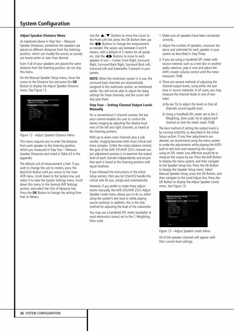
26 SYSTEM CONFIGURATION
System Configuration
Adjust Speaker Distance Menu
As explained above in Step Two – MeasureSpeaker Distances, sometimes the speakers areplaced at different distances from the listening-position, which can muddy the sound, as soundsare heard earlier or later than desired.
Even if all of your speakers are placed the samedistance from the listening position, do not skipthis menu.
On the Manual Speaker Setup menu, move thecursor to the Distance line and press the OKButton to display the Adjust Speaker Distancemenu. See Figure 12.
Figure 12 – Adjust Speaker Distance Menu
This menu requires you to enter the distancefrom each speaker to the listening position,which you measured in Step Two – MeasureSpeaker Distances and noted in Table A3 in theappendix.
The default unit of measurement is feet. If youwish to change the unit to meters, press theBack/Exit Button until you return to the mainAVR menu. Scroll down to the System line, andselect it to view the System Settings menu. Scrolldown this menu to the General AVR Settingssection, and select the Unit of Measure line.Press the OK Button to change the setting fromFeet to Meters.
Use theK/L Buttons to move the cursor tothe Front Left line, press the OK Button then usetheM/N Buttons to change the measurementas needed. The values vary between 0 and 9meters, with a default of 3 meters for all speak-ers. Use theM/N Buttons to move to eachspeaker in turn – Center, Front Right, SurroundRight, Surround Back Right, Surround Back Left,Surround Left and Subwoofer, if present in yoursystem.
NOTE:When the multiroom system is in use, thesurround back channels are automaticallyassigned to the multiroom system, as mentionedearlier. You will not be able to adjust the delaysettings for these channels, and the cursor willskip past them.
Step Four – Setting Channel Output LevelsManually
For a conventional 2-channel receiver, the bal-ance control enables the user to control thestereo imaging by adjusting the relative loud-ness of the left and right channels, as heard atthe listening position.
With up to seven main channels plus a sub-woofer, imaging becomes both more critical andmore complex. Unlike the rotary balance control,the goal of the AVR 355/AVR 255’s channel out-put adjustment process is to examine the outputlevel of each channel independently and ensurethat each is heard at the listening position withequal loudness.
If you followed the instructions in the InitialSetup section, then you let EzSet/EQ handle thiscritical task for you, simply and automatically.
However, if you prefer to make these adjust-ments manually, the AVR 355/AVR 255’s AdjustSpeaker Levels menu allows you to do so, eitherusing the system’s test tone or while playingsource material. In addition, this is the onlymethod for adjusting the level of the subwoofer.
You may use a handheld SPL meter (available atmost electronics stores) set to the C-Weighting,Slow scale.
1. Make sure all speakers have been connectedcorrectly.
2. Adjust the number of speakers, crossover dis-tance and submode for each speaker in yoursystem as described in Step Three.
3. If you are using a handheld SPL meter withsource material, such as a test disc or anotheraudio selection, play it now and adjust theAVR’s master volume control until the metermeasures 75dB.
4. There are several methods of adjusting thechannel output levels, using either the testtone or source materials. In all cases, you maymeasure the channel levels in one of twoways:
a) By ear. Try to adjust the levels so that allchannels sound equally loud.
b) Using a handheld SPL meter set to the C-Weighting, Slow scale. Try to adjust eachchannel so that the meter reads 75dB.
The best method of setting the output levels isby running EzSet/EQ, as described in the InitialSetup section. If any finer adjustments aredesired, we recommend using the menu systemto make the adjustments while playing the AVR’sbuilt-in test tone and measuring the outputusing an SPL meter. Less effective would be tomeasure the output by ear. Press the AVR Buttonto display the menu system, and then navigateto the Speaker Setup line. Press the OK Buttonto display the Speaker Setup menu. SelectManual Speaker Setup, press the OK Button, andthen navigate to the Level Adjust line. Press theOK Button to display the Adjust Speaker Levelsmenu. See Figure 13.
Figure 13 – Adjust Speaker Levels Menu
All of the speaker channels will appear withtheir current level settings.
SYSTEM CONFIGURATION 27
ENGLI
SH
System Configuration
Reset Levels: If you wish to start by resettingall of the levels to their factory defaults of 0dB,scroll down to this line and press the OK Button.The levels will be reset.
If you are using an external source to set youroutput levels, simply navigate to each channel,press the OK Button and use theM/N Buttonsto adjust the level as desired between –10dBand +10dB. All channels default to 0dB.
If you would like to set your levels using theAVR 355/AVR 255’s internal test tone, adjust theTEST TONE line as follows.
Test Tone: This line determines whether the testtone is active. To begin the process of setting thelevels, press the OK Button repeatedly to selectthe OFF, AUTO or MANUAL setting. Any time youmanually move the cursor out of the channellistings area of the screen, this setting will auto-matically change to OFF, stopping the test tone.
When this setting reads AUTO, the test tone willautomatically circulate to all channels, pausingfor a few moments at each channel and thenmoving to the next channel several secondslater, as indicated by the highlight bar. You mayadjust the level for any channel when the testtone is paused there by using theM/N Buttons.You may also use theK/L Buttons at anytime to move the cursor to another line, and thetest tone will follow the cursor.
When this setting reads MANUAL, the test tonewill not move to the next channel until you usetheK/L Buttons to move it.
NOTE: Setting the channel levels while one sur-round mode is active does not carry over toother mode groups. We recommend that afteryou have set the levels satisfactorily in onemode, you note the results and change to othersurround modes. For those modes that don’treflect your level settings, you may either copythe settings you obtained (as a short cut), orredo the procedure to determine the correct set-tings for those surround modes.
When you have finished adjusting the speakerlevels, select the SAVE option so that the set-tings will not be lost. Record the level settings inTable A3 in the appendix for future reference.
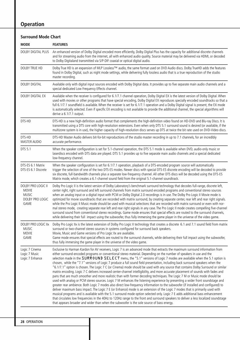
Operation
28 OPERATION
Surround Mode Chart
MODE FEATURES
DOLBY DIGITAL PLUS An enhanced version of Dolby Digital encoded more efficiently, Dolby Digital Plus has the capacity for additional discrete channelsand for streaming audio from the internet, all with enhanced audio quality. Source material may be delivered via HDMI, or decodedto Dolby Digitaland transmitted via S/P-DIF coaxial or optical digital audio.
DOLBY TRUE HD Dolby True HD is an expansion of MLP Lossless™ audio, the same format used on DVD Audio discs. Dolby TrueHD adds the featuresfound in Dolby Digital, such as night mode settings, while delivering fully lossless audio that is a true reproduction of the studiomaster recording.
DOLBY DIGITAL Available only with digital input sources encoded with Dolby Digital data. It provides up to five separate main audio channels and aspecial dedicated Low Frequency Effects channel.
DOLBY DIGITAL EX Available when the receiver is configured for 6.1/7.1 channel operation, Dolby Digital EX is the latest version of Dolby Digital.Whenused with movies or other programs that have special encoding, Dolby Digital EX reproduces specially encoded soundtracks so that afull 6.1/7.1 soundfield is available.When the receiver is set for 6.1/7.1 operation and a Dolby Digital signal is present, the EX modeis automatically selected. Even if specific EX encoding is not available to provide the additional channel, the special algorithms willderive a 6.1/7.1 output.
DTS-HD DTS-HD is a new high-definition audio format that complements the high-definition video found on HD-DVD and Blu-ray Discs. It istransmitted using a DTS core with high-resolution extensions. Even when only DTS 5.1 surround sound is desired (or available, if themultizone system is in use), the higher capacity of high-resolution discs serves up DTS at twice the bit rate used on DVD-Video discs.
DTS-HD DTS-HD Master Audio delivers bit-for-bit reproductions of the studio master recording in up to 7.1 channels, for an incrediblyMASTER AUDIO accurate performance.
DTS 5.1 When the speaker configuration is set for 5.1-channel operation, the DTS 5.1 mode is available when DVD, audio-only music orlaserdiscs encoded with DTS data are played. DTS 5.1 provides up to five separate main audio channels and a special dedicatedlow-frequency channel.
DTS-ES 6.1 Matrix When the speaker configuration is set for 6.1/7.1 operation, playback of a DTS-encoded program source will automaticallyDTS-ES 6.1 Discrete trigger the selection of one of the two DTS-ES modes. Newer discs with special DTS-ES discrete encoding will be decoded to provide
six discrete, full-bandwidth channels plus a separate low-frequency channel. All other DTS discs will be decoded using the DTS-ESMatrix mode, which creates a 6.1-channel sound field from the original 5.1-channel soundtrack.
DOLBY PRO LOGIC II Dolby Pro Logic II is the latest version of Dolby Laboratory’s benchmark surround technology that decodes full-range, discrete left,MOVIE center right, right surround and left surround channels from matrix surround encoded programs and conventional stereo sourcesMUSIC when an analog input or a digital input with PCM or Dolby Digital 2.0 recordings is in use. The Dolby Pro Logic II Movie mode isDOLBY PRO LOGIC optimized for movie soundtracks that are recorded with matrix surround, by creating separate center, rear left and rear right signals.GAME while the Pro Logic II Music mode should be used with musical selections that are recorded with matrix surround or even with nor-
mal stereo mode, creating separate rear left and rear right signals in any case. The Pro Logic II mode creates compelling five-channelsurround sound from conventional stereo recordings. Game mode ensures that special effects are routed to the surround channels,while delivering their full impact using the subwoofer, thus fully immersing the game player in the universe of the video game.
DOLBY PRO LOGIC IIx Dolby Pro Logic IIx is the latest extension of Dolby Pro Logic II technology that creates a discrete 6.1 and 7.1 sound field from matrixMUSIC surround or two-channel stereo sources in systems configured for surround back speakers.MOVIE Movie, Music and Game versions of Pro Logic IIx are available.GAME Game mode ensures that special effects are routed to the surround channels, while delivering their full impact using the subwoofer,
thus fully immersing the game player in the universe of the video game.
Logic 7 Cinema Exclusive to Harman Kardon for AV receivers, Logic 7 is an advanced mode that extracts the maximum surround information fromLogic 7 Music either surround-encoded programs or conventional stereo material. Depending on the number of speakers in use and theLogic 7 Enhance selection made in the SURROUND SELECT menu, the “5.1” versions of Logic 7 modes are available when the 5.1 option is
chosen, while the “7.1” versions of Logic 7 produce a full sound field presentation, including back surround speakers when the“6.1/7.1” option is chosen. The Logic 7 C (or Cinema) mode should be used with any source that contains Dolby Surround or similarmatrix encoding. Logic 7 C delivers increased center-channel intelligibility, and more accurate placement of sounds with fades andpans that are much smoother and more realistic than with former decoding techniques. The Logic 7 M or Music mode should beused with analog or PCM stereo sources. Logic 7 M enhances the listening experience by presenting a wider front soundstage andgreater rear ambience. Both Logic 7 modes also direct low-frequency information to the subwoofer (if installed and configured) todeliver maximum bass impact. The Logic 7 E (or Enhance) mode is an extension of the Logic 7 modes that is primarily used withmusical programs and is available with the 5.1 surround mode option selected only. Logic 7 E adds additional bass enhancementthat circulates low frequencies in the 40Hz to 120Hz range to the front and surround speakers to deliver a less localized soundstagethat appears broader and wider than when the subwoofer is the sole source of bass energy.
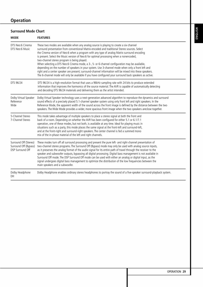
Surround Mode Chart
MODE FEATURES
DTS Neo:6 Cinema These two modes are available when any analog source is playing to create a six-channelDTS Neo:6 Music surround presentation from conventional Matrix-encoded and traditional Stereo sources. Select
the Cinema version of Neo:6 when a program with any type of analog Matrix surround encodingis present. Select the Music version of Neo:6 for optimal processing when a nonencoded,two-channel stereo program is being played.When selecting a DTS Neo:6 Cinema mode, a 3-, 5- or 6-channel configuration may be available,depending on the number of speakers in your system. Use 3-channel mode when only a front left andright and a center speaker are present; surround-channel information will be mixed into these speakers.The 6-channel mode will only be available if you have configured your surround back speakers as active.
DTS 96/24 DTS 96/24 is a high-resolution format that uses a 96kHz sampling rate with 24 bits to produce extendedinformation that improves the harmonics of the source material. The AVR is capable of automatically detectingand decoding DTS 96/24 materials and delivering them as the artist intended.
Dolby Virtual Speaker Dolby Virtual Speaker technology uses a next-generation advanced algorithm to reproduce the dynamics and surroundReference sound effects of a precisely placed 5.1-channel speaker system using only front left and right speakers. In theWide Reference Mode, the apparent width of the sound across the front image is defined by the distance between the two
speakers. The Wide Mode provides a wider, more spacious front image when the two speakers areclose together.
5-Channel Stereo This mode takes advantage of multiple speakers to place a stereo signal at both the front and7-Channel Stereo back of a room. Depending on whether the AVR has been configured for either 5.1 or 6.1/7.1
operation, one of these modes, but not both, is available at any time. Ideal for playing music insituations such as a party, this mode places the same signal at the front-left and surround-left,and at the front-right and surround-right speakers. The center channel is fed a summed monomix of the in-phase material of the left and right channels.
Surround Off (Stereo) These modes turn off all surround processing and present the pure left- and right-channel presentation ofSurround Off (Bypass) two-channel stereo programs. The Surround Off (Bypass) mode may only be used with analog source inputs,DSP Surround Off as it preserves the analog format of the audio signal for its entire path of travel through the receiver to the
speaker and subwoofer outputs, bypassing all digital processing. Digital bass management is not available inSurround Off mode. The DSP Surround Off mode can be used with either an analog or digital input, as thesignal undergoes digital bass management to optimize the distribution of the low frequencies between themain speakers and a subwoofer.
Dolby Headphone Dolby Headphone enables ordinary stereo headphones to portray the sound of a five-speaker surround-playback system.DH
Operation
ENGLI
SH
OPERATION 29

Operation
Basic Operation
Once you have completed the setup and configu-ration of the AVR, it is simple to operate andenjoy. The following instructions should befollowed for you to maximize your enjoyment ofyour new receiver:
Turning the AVR On or Off•When using the AVR for the first time, you mustpress theMain Power Switch on the rearpanel to turn the unit on. This places the unit inStandby mode, as indicated by the amber color ofthe Power Indicator 3. Once the unit is inStandby, you may begin a listening session bypressing the System Power Control 2 or onthe front panel or theAVR Power ON Button on the remoteA.Note that the Power Indicator 3 turns white.This will turn the unit on and return it to the inputsource that was last used. The unit may also beturned on from Standby by pressing any of theSource Selector buttons on the remoteC,except the "Bridge" Button on the AVR 355remote.
To turn the unit off at the end of a listeningsession, simply press the System PowerControl 2 on the front panel or the AVRPower Off Button B on the remote. Powerwill be shut off to any equipment plugged intothe front panel Switched AC Outlets andthe Power Indicator 3 will turn amber.
When the remote is used to turn the unit “off” itis actually placing the system in a Standby mode,as indicated by the amber color of the PowerIndicator 3.
When you will be away from home for anextended period of time it is always a good ideato completely turn the unit off with the rearpanel Main Power Switch .
NOTE: All preset memories may be lost if theunit is left turned off with the Main PowerSwitch for more than two weeks.
Using the Sleep Timer• To program the AVR for automatic turn-off,press the Sleep Button G on the remote. Eachpress of the button will increase the time beforeshut down in the following sequence:
The sleep time will be displayed in the MainInformation Display # and it will countdown until the time has elapsed.
When the programmed sleep time has elapsed,the unit will automatically turn off (to Standbymode). Note that the front panel display will dimto one half brightness when the Sleep functionis programmed. To cancel the Sleep function,press and hold the Sleep Button G until theinformation display returns to normal brightnessand the Sleep indicator numbers disappear andthe words SLEEP OFF appear in theMain Information Display #.
Mute FunctionTo temporarily mute all speakers and the head-phones, press the MuteButton on the remoteR. Any recording in progress will not be affect-ed. The MUTE message will appear in the displayas a reminder. To restore normal audio, eitherpress the Mute Button again, or adjust the vol-ume. Turning off the AVR will also end muting.
Audio EffectsDepending on the specific characteristics of yourlistening room, you may wish to tweak some ofthe audio settings, such as tone controls, toimprove performance. Access these settings fromthe Audio Effects Button 9D, as described inthe Advanced Functions section.
It is not necessary to adjust the Audio Effectssettings to enjoy your new AVR.We recommendleaving the settings at their default values untilyou are more familiar with your system.
Video ModesThe settings in the Video Modes menu are usedto fine-tune the picture if necessary after makingall adjustments on the video display. It is recom-mended that you leave the settings at theirdefaults. See the Advanced Functions section fordetailed information.
Source Selection
For direct access to any source, press its SourceSelector ButtonC on the remote control.Alternatively, Sources can be selected from theSource Selection Menu, available by pressing theAVR Settings ButtonY on the remote, followedby the OK ButtonX. The list showing availableinputs slides in from the right. Simply scroll upand down to the desired input, then press OK onthe remote.
• The input source may also be changed bypressing the front-panel Source List Button@. This opens the on-screen Source SelectionMenu with the slide-in Source List already open.If you are not using your TV for on-screen refer-ence, use the Front Panel Information Displaywhich shows the information you need. Scroll upand down with theKL Buttons5, selectthe desired Input by pressing the OK Button6and exit the Source Selection function by press-ing the Source List Button@ again.
• The front-panel Video Inputs (, OpticalDigital Input ) or the Coaxial DigitalInput * may be used to connect a device suchas a video game or camcorder to your homeentertainment system on a temporary basis.
• As the input source is changed, the new inputname will appear momentarily as on-screeninformation in the video display. The input namewill also appear in the Main InformationDisplay #.
• (AVR 355 only) When Digital MediaPlayer (DMP) source is selected, if a compatibleApple iPod device is inserted in an optionalHarman Kardon that is connected to
DMP Connector on the rearpanel, function messages will appear on anyvideo display connected to the AVR, and theremote control may be used to navigate the iPodand access many of its functions. The functionmessages will also appear in the front-panel dis-play, and the iPod’s battery may be charged. Seethe owner’s guides for and your iPodfor more information.
Video Input Selection
When a source is selected, the AVR switches to aVideo Input that has either been assigned tothat Source by you, or to the default Video Inputif you have not assigned any. All inputs exceptRadio are combined Audio and Video Inputs,functioning as audio-only inputs when no videosignal is present. Refer to the Setup section ofthis manual for explanation of assigning videoinputs to each source.
30 OPERATION
Operation
HDMI-equipped multichannel discplayer:• Connect the player’s HDMI output to one ofthe AVR’s HDMI Inputs. No other connectionsare necessary.
• Assign the HDMI Input to both the Audio andVideo Input From Source settings in the SourceInfo menu.
HDMI-equipped multichannel disc playerthat does not output multichannel audiovia HDMI:
• Connect the player’s HDMI output and its mul-tichannel analog audio outputs to one of theAVR’s HDMI Inputs and to the AVR’s 6-/8-Channel Analog Audio Inputs.
• Assign the HDMI Input to both the Audio andVideo Input From Source settings in the SourceInfo menu.
• Assign the 6-/8-Channel Analog Audio Inputsto the Audio Auto Polling setting in the SourceInfo menu.
• When listening to DVD-Video discs, CDs orother materials outputting standard-definitiondigital audio, do nothing, as long as the HDMIInput is assigned to the Audio Input From Sourcesetting.
• When listening to high-resolution multichanneldiscs, the AVR’s auto polling feature will auto-matically switch to the multichannel analogaudio inputs.
Multichannel disc player without HDMIoutput, or when video display has noHDMI input:
• Connect the player’s component video outputsto one set of Component Video Inputs on theAVR. Depending on the capabilities of the playerand your video display, you may need to use acomposite or S-video connection instead.
• Connect the player’s digital audio output to acorresponding available digital audio input onthe AVR.
• Connect the player’s multichannel audio out-puts to the AVR’s 6-/8- Channel Analog AudioInputs.
• Assign the correct audio and video inputs tothe Audio and Video Input From Source Settingsin the Source Info menu.
• Assign the 6-/8-Channel Analog Audio Inputsto the Audio Auto Polling setting in the SourceInfo menu.
• When listening to DVD-Video discs, CDs orother materials outputting standard-definitiondigital audio, do nothing, as long as the correctdigital audio input is assigned to the Audio InputFrom Source setting.
• When listening to high-resolution multichanneldiscs, the AVR’s auto polling feature will auto-matically switch to the multichannel analogaudio inputs.
NOTE: The 6-/8-Channel Inputs pass the incom-ing signals directly to the volume control, with-out digitizing or processing them. Configure thebass management settings (i.e., speaker size,delay and output level) on your source device tomatch the settings programmed using EzSet/EQ,which may be viewed using the Speakers Setupmenu (see Advanced Functions section). Consultthe owner’s guide for your multichannel playerfor more information.
6-Channel/8-Channel Direct InputThe 6-/8-Channel Analog Audio Inputs are usedwhen playing certain multichannel discs, such asDVD-Audio, HD-DVD, SACD and Blu-ray Discs,on a player that decodes the audio and outputsit via its multichannel analog audio outputs butnot via its HDMI output.
Controls and Use of Headphones• Adjust the volume to a comfortable level usingthe front panel Volume Control 1 or remoteVolume Up/Down P buttons.
• To temporarily silence all speaker outputspress the Mute buttonR on the RemoteControl. This will interrupt the output to allspeakers and the headphone jack, but it will notaffect any recording or dubbing that may be inprogress.When the system is muted, the wordMUTE will appear in the Main InformationDisplay #. Press the Mute buttonR againto return to normal operation.
• For private listening, plug the 6.3 mm stereophone plug from a pair of stereo headphonesinto the front panel Headphone Jack 4. Notethat when the headphone’s plug is connected,the word DOLBY H:DH appears in the MainInformation Display # and all speakers willbe silenced.When the headphone plug isremoved, the audio feed to the speakers will berestored.
• When the headphones are in use, you maytake advantage of the Dolby Headphone modesto bring added spaciousness to headphone lis-tening. Press the Surround Mode Button onthe front panel% to switch between DolbyHeadphone and Bypass to select the one thatyou prefer.
Surround Mode SelectionOne of the most important features of theAVR 255/AVR 355 is its ability to reproduce afull multichannel surround sound field from digi-tal sources, analog matrix surround encodedprograms and standard stereo or even monoprograms.
Selection of a surround mode is based on per-sonal taste, as well as the type of programsource material being used. For example, CDs,motion pictures or TV programs bearing the logoof one of the major surround-encoding process-es, such as Dolby Surround should be played ineither the Dolby Pro Logic II or IIx Movie (withmovies) or Music (with music) surround mode,with any DTS NEO:6 mode or with HarmanKardon´s exclusive Logic 7 Movie Mode, to cre-ate a full range 5.1 channel or (with Logic 7 andDTS NEO:6) even 7.1 channel surround signalfrom surround encoded programs, with a stereo-phonic left and right rear signal, just as it wasrecorded
VIDEO TROUBLESHOOTING TIPS:If a video source is playing and there is no pic-ture:
• Check that you have selected the source towhich the video input was assigned.
• Check the wires for a loose or incorrect con-nection.
• Check that you have selected the correctvideo input on the display device (TV).
• Try pressing the Resolution Button on thefront panel to check that the correct videooutput resolution is selected and select theproper resolution for your screen.
Additional tips for systems using HDMI:
• Turn off all devices (including the TV, AVRand any source components).
• Unplug the HDMI cables starting with thecable between the TV and AVR, and contin-uing with the cables between the AVR andeach source device.
• Carefully reconnect the cables from thesource devices to the AVR, and connect thecable from the AVR to the TV last.
• Turn on the devices in this order: TV, thenAVR, then source devices.
ENGLI
SH
OPERATION 31

Operation
Note that when Dolby Digital 2.0 signals (e.g."D.D. 2.0" tracks from DVD), that are encodedwith Dolby Pro Logic information, are receivedvia any digital input, the Dolby Pro Logic IIMovie mode will be selected automatically (inaddition to the Dolby Digital mode) and willdecode a full range 5.1 channel surround soundeven from those recordings.
To create wide, enveloping sound field environ-ments and defined pans and flyovers with allanalog stereo recordings select the Dolby ProLogic II Music or Emulation mode or HarmanKardon’s exclusive Logic 7 Music mode for adramatic improvement in comparison to theDolby Pro Logic ( I ) mode of former times.
NOTE: Once a program has been encoded withmatrix surround information, it retains the sur-round information as long as the program isbroadcast in stereo. Thus, movies with surroundsound may be decoded via any of the analog sur-round modes such as Pro Logic II or IIx Cinema,Logic 7 Cinema or DTS Neo:6 Cinema, when theyare broadcast via conventional TV stations, cable,pay-TV and satellite transmission. In addition, agrowing number of made-for-television programs,sports broadcasts, radio dramas and music CDsare also recorded in surround sound. You mayview a list of these programs at theDolby LaboratoriesWeb site at www.dolby.com
Even when a program is not listed as carryingintentional surround information, you may findthat the Dolby Pro Logic II or IIx Music, DTSNEO:6 Music or Logic 7 Music or Enhancedmodes often deliver enveloping surround presen-tations through the use of the natural surroundinformation present in all stereo recordings.
However, for stereo programs without anysurround information the 5/7CH Stereo modesshould be tried (effective particularly with old”extreme” stereo recordings). And when you useonly two front channel speakers you should selectany of the Dolby Virtual Speaker surround modes,delivering a virtually three dimensional soundspace with two speakers only.
Surround modes are selected using either thefront panel controls or the remote. To select anew surround mode from the front panel, firstpress the Surround Mode Button%S toenter the Surround Modes Menu. Then use theKL Buttons5F to select the signal typethat you want to modify and confirm with theOK Button to open the list of available SurroundModes for this signal type. Again select thedesired Surround Mode and confirm with the OKButton. Press the Back/Exit Button^O toexit the menu.
Note that the Dolby Digital or DTS modes mayonly be selected when a digital input is in use. Inaddition, when a digital source is present, theAVR will automatically select and switch to thecorrect mode (Dolby Digital or DTS), regardlessof the mode that has been previously selected.For more information on selecting digital sources,see the following section of this manual.
When the 6-Channel/8-Channel direct inputs arein use there is no surround processing, as theseinputs take the analog output signals from anoptional, external DVD-Audio or SACD player, oranother source device and carry them straightthrough to the volume control.
To listen to a program in traditional two-channelstereo, using the front left and front rightspeakers only (plus the subwoofer, if installedand configured), select 2 CH Stereo in theSurround Modes Menu.
Digital Audio Signals
Digital audio signals offer the benefit of greatercapacity, which allows recording artists toencode center and surround channel informationdirectly into the signal. The result is improvedsound quality and startling directionality, sinceeach of these channels is reproduced discretely.
Alternatively, the artist may encode only twochannels, but the digital signal allows for ahigher sampling rate that delivers greater detail.High-resolution recordings usually soundextraordinarily distortion-free at all frequencies,but especially at high frequencies.
Multichannel digital recordings usually are foundin the 5.1-, 6.1- or 7.1-channel formats. Thechannels included in a 5.1-channel recording arefront left, front right, center, surround left,surround right and LFE. The LFE channel isdenoted as “.1” to represent the fact that it isnot full-range, being limited to the lowfrequencies.
6.1-Channel recordings add a single surroundback channel, and 7.1-channel recordings addsurround back left and surround back rightchannels to the 5.1-channel configuration. Newformats, such as Dolby TrueHD, Dolby DigitalPlus, DTS-HD and DTS-HD Master Audio, areavailable in 7.1-channel configurations. TheAVR 355/AVR 255 is able to play the new audioformats, delivering a more exciting home theaterexperience.
NOTE: To use the 6.1- and 7.1-channelsurround modes, the AVR 355/AVR 255 must beconfigured so that the Surround Back channelsare enabled. See the Manual Setup section onpage 24 for more information.
Digital formats include Dolby Digital 2.0 (twochannels only), Dolby Digital 5.1, Dolby DigitalEX, Dolby Digital Plus, Dolby TrueHD, DTS-HD,DTS-HD Master Audio, DTS 5.1, DTS-ES (6.1Matrix and Discrete), DTS 96/24, 2-channel PCMmodes in 32kHz, 44.1kHz, 48kHz or 96kHz, and5.1 or 7.1 multichannel PCM.
When a digital signal is received, the AVR 355/AVR 255 detects the encoding method and thenumber of channels. The number of channelsencoded will appear briefly in the front-paneldisplay as three numbers, separated by slashes(e.g., “3/2/.1”).
The first number indicates the number of frontchannels in the signal:
“1” represents a monophonic recording, usuallyan older program that has been digitallyremastered or, more rarely, a modernprogram for which the director has chosen aspecial effect.
“2” indicates the presence of the left and rightchannels, but no center channel.
“3” indicates that all three front channels (left,right and center) are present.
The second number indicates whether anysurround channels are present:
“0” indicates that no surround information ispresent.
“1” indicates that a matrixed surround signal ispresent.
“2” indicates discrete left and right surroundchannels.
“3” is used with DTS-ES bitstreams to representthe presence of the discrete surround backchannel in addition to the side surround leftand right channels.
“4” is used with 7.1-channel digital formats,including Dolby TrueHD, Dolby Digital Plus, DTS-HD and DTS-HD Master Audio, to indicate thepresence of two discrete side surround channelsand two discrete back surround channels.
The third number is used for the LFE channel:
“0” indicates no LFE channel.
“.1” indicates that an LFE channel is present.
The 6.1-channel signals – Dolby Digital EX andDTS-ES Matrix and Discrete – each include a flagmeant to signal the receiver to decode thesurround back channel.
For Dolby Digital EX materials, the incomingbitstream will be displayed as 3/2/.1 EX-ON. Forolder discs, the display may show EX-OFF, butyou will still be able to select the Dolby DigitalEX mode manually.
32 OPERATION

Operation
For DTS-ES materials, the incoming bitstreamwill be displayed as 3/3/.1 ES-ON.
When a PCM signal is received, the PCMmessage, followed by the sampling rate of thesignal (32kHz, 44.1kHz, 48kHz or 96kHz), willappear in the front-panel display.
In addition, the Speaker/Channel InputIndicators will indicate the number of channelsdiscretely encoded in the signal by displaying aletter inside that channel’s speaker box. A linewill connect the SBL and SBR boxes when a 6.1-channel signal is detected, indicating that thesame signal is playing through both speakers.The letters flash when no signal is present, suchas when a DVD is paused.
Speaker/Channel Input Indicators
When only two channels – left and right – arepresent, the analog surround modes may beused to decode the signal into the remainingchannels.
Figure 14 – Surround Modes
If you would prefer a different surround formatthan the native signal’s digital encoding, pressthe Surround Modes Button to display theSurround Modes menu (see Figure 14).
The Auto Select option (the first line) uses thenative signal’s digital encoding, e.g. DolbyDigital or DTS. For two-channel materials, theAVR defaults to Logic 7 Movie mode. If youprefer a different surround processing mode,select the appropriate line from the menu:Virtual Surround, Stereo, Movie, Music or VideoGame.
Each line is set to a default surround mode:
• Virtual Surround: Dolby Virtual SpeakerReference
• Stereo: 7-channel stereo
• Movie: Logic 7 Movie
• Music: Logic 7 Music
• Video Game: Logic 7 Game
You may change each line’s setting to a differentsurround mode. The choice of new modesdepends on the number of speakers in yoursystem.
• Virtual Surround: Dolby Virtual SpeakerReference or Wide
• Stereo: 2-channel stereo, 5-channel stereo or7-channel stereo
• Movie: Logic 7 Movie, DTS Neo 6:Cinema,Dolby Pro Logic II Movie, Dolby Pro Logic IIxMovie
• Music: Logic 7 Music, DTS Neo 6:Music,Dolby Pro Logic II Music, Dolby Pro Logic IIxMusic
• Video Game: Logic 7 Game, Dolby Pro LogicII Game, Dolby Pro Logic IIx Game
When one of the Dolby Pro Logic II Music modesis selected, access to the Edit submenu becomesavailable. This submenu may be used to adjustspecial settings available only in Music mode:Center Width, Dimension and Panorama.
Once you have programmed the defaultsurround mode for each type of program, simplyselect the line from the Surround Modes menuany time you wish to override the AVR’sautomatic surround mode selection. The AVR willuse the same surround mode the next time thesource input is selected.
NOTE: Dolby Digital 2.0 signals may alsoinclude a Dolby Surround flag indicating DS-ONor DS-OFF, depending on whether the 2-channelbitstream contains only stereo information, or adownmix of a multichannel program that can bedecoded by the Dolby Pro Logic decoder in theAVR. By default, these signals are played inDolby Pro Logic IIx Movie mode, but you mayselect another Dolby surround mode manually.
Surround Modes
Surround mode selection is dependent upon theformat of the incoming audio signal, as well aspersonal taste. There is no harm inexperimenting with all of the modes availablewith any given source material. Informationabout the Dolby and DTS modes is available onthe companies’ Web sites: www.dolby.com andwww.dtsonline.com.
When in doubt, check the jacket of your DVD formore information on which surround modes areavailable on the disc. Usually, nonessentialsections of the disc, such as trailers, extramaterials or the disc menu, are only available inDolby Digital 2.0 (2-channel) or PCM 2-channelmode. If the main title is playing and the lettersin the Speaker/Channel Input Indicators are notlit for all speaker locations, look for an audio orlanguage setup section in the disc’s menu. Also,make sure your DVD player’s audio output is setto the original bitstream rather than just PCM.Check the DVD player’s output setting bystopping play of the disc and checking the DVDplayer’s menu system.
Different surround modes may only be availablewith certain input signals or bitstream formats.For any incoming signal, only a limited numberof surround modes are available. Although thereis never a time when all of the AVR 355/AVR 255’s surround modes are available, thereis usually a wide variety of modes available for agiven input.
To select a surround mode, press the SurroundModes ButtonS, select either Auto Select -AVR Selects Best Mode, or move the blue line tothe other options: Virtual Surround, Stereo,Movie, Music and Video Game. Each of these 5options permit several selections, accessed bypressing the OK Button (See Figure 14).
Dolby Surround Settings
Some additional settings are available for Dolbymodes. Three settings are active only when theDolby Pro Logic II or IIx Music modes have beenselected. See Figure 15.
Figure 15 – Dolby Pro Logic II/IIx Music ModeSettings
Center Width: This setting affects how vocalssound through the three front speakers. A highernumber (up to 7) focuses the vocal informationtightly on the center channel. Lower numbersbroaden the vocal soundstage across the threespeakers. Use the ‹/› Buttons to change thesetting.
Dimension: This setting affects the depth of thesurround presentation, allowing you to “move”the sound toward the front or rear of the room.The setting of “0” is a neutral default. Setting“F-3” moves the sound mostly toward the frontof the room, while setting “R-3” moves thesound mostly toward the rear. Use the ‹/›Buttons to change the setting.
Panorama:With the Panorama mode turnedON, some of the sound from the front speakersis moved to the surround speakers, creating anenveloping “wraparound” type of effect. Eachpress of the OK Button toggles the setting on oroff.
LC
LFE
R
SL SR
SBL SBR
ENGLI
SH
OPERATION 33

34 OPERATION
Operation
Night Mode
Night mode is available with some Dolby Digitalprograms, if it has been encoded in the material.It compresses the peak sound levels, maintainingthe intelligibility of the dialogue and quieterpassages, while reducing the loudness of specialeffects and louder passages to avoid disturbingothers. Night Mode is accessed from the AudioEffects menu. Press the Audio Effects Button andscroll down to the Night Mode line. Three levelsof compression are available:
Off: At this setting, there is no compression, asthe Night mode is deactivated.
Half: A mild compression is applied.
Full: More compression is applied.
Feel free to experiment and simply cycle throughall of the available surround modes at any time;you cannot cause any problems for the AVR 355/AVR 255 by doing so.
NOTE: To access 6.1- and 7.1-channel modes,such as Dolby Digital EX, DTS-ES, Logic 7 (7.1modes), DTS Neo:6 (6.1 modes), and 7-channelStereo, you must enable the surround backchannels as explained in the Manual Setupsection. You should not enable these channels ifyou don’t have surround back speakers in yoursystem.
Tape Recording
In normal operation, the audio or video sourceselected for listening through the AVR is sent tothe record outputs. This means that any programyou are watching or listening to may be record-ed simply by placing machines connected to theoutputs for Analog Outputs or Video 1Outputs in the record mode.
When a digital audio recorder is connected tothe Coaxial Digital Output, you are ableto record the digital signal using a CD-R,MiniDisc or other digital recording system.
NOTES:• The digital outputs are active only when a digi-tal signal is present, and they do not convert ananalog input to a digital signal, or change the for-mat of the digital signal (e.g. Dolby Digital toPCM or vice versa). In additon, the digital recordermust be compatible with the output signal. Forexample, the PCM digital output from a CD playermay be recorded on a CD-R or MiniDisc, butDolby Digital or DTS signals may not.
• To make an analog recording from a digitalsource is possible, but only from a PCM source(not Dolby Digital or DTS) and correctly only with"Surround Off" mode (with any Surround modeonly the L/R front signals will be fed to therecord outputs).
Using (AVR 355 only)
When Harman Kardon’s (optional) isconnected and a compatible Apple® iPod® isdocked in The Bridge, press the DMPSelector ButtonC on the Remote Control orthe Source List@ followed by the Up/DownArrows to choose the iPod as the input sourceallowing playback of audio, video and still-imagematerials on your iPod through your high-qualityaudio/video system. Pressing the DMPSelector Button C will also activate the AVRremote’s control codes for the iPod, and you mayalso use the front-panel controls to operate theiPod.
When The Bridge is properly connected and acompatible iPod is properly docked, the UpperDisplay Line # will read DMP/CONNECTED. Once that message appears,use the remote or front-panel buttons to controlthe iPod. See the Function List Table on page 46for a listing of the remote control buttons thathave been programmed to control the iPod.
Figure 16 - On Screen Display, iPod playing
Figure 17 - On Screen Display, iPod MenuSelection
Complete details on operating an iPod usingand an AVR remote are furnished
with .
While a selection is playing, the song title, artistand album name, if available on the iPod, willscroll across the upper line in the front panelMessage Display #. The lower line willdisplay the elapsed time of the track on the left,the play mode icon, and the time remaining onthe right.
In addition, if a video display is connected to theAVR, a screen will appear briefly to display infor-mation about the iPod’s status and the track. Thetop line will display the play mode icon, with thephrase “Now Playing” appearing to the right toremind you that you are viewing the status ofthe current track, as opposed to another menuscreen. Below that the AVR displays the totalnumber of tracks in the current play list on theright (all materials on the iPod are consideredone of the play lists) with the number of thecurrent track on the left. The song title, artist andalbum are displayed. At the bottom of the screenis a graphic bar indicating the current playposition within the track, with the elapsed andremaining times appearing below the bar.
After a period of time the screen may disappearfrom view. The length of time is set using theFull-OSD Time Out setting in the System Settingsmenu (described in the Advanced Functions sec-tion). You may restore the Now Playing screen toview by pressing either of the ‹/› Buttons F,and you may then navigate the menus asexplained above.
NOTE: It is strongly recommended that you usea screen saver built into your video display toavoid possible damage from “burn-in” that mayoccur with plasma and many CRT displays whena still image, such as a menu screen, remains ondisplay for an extended period of time.
Memory Backup
This product is equipped with a memory backupsystem that preserves tuner presets and systemconfiguration information if the unit is turned offcompletely, accidentally unplugged or subjectedto a power outage. This memory will last forapproximately two weeks, after which time allinformation must be reentered.
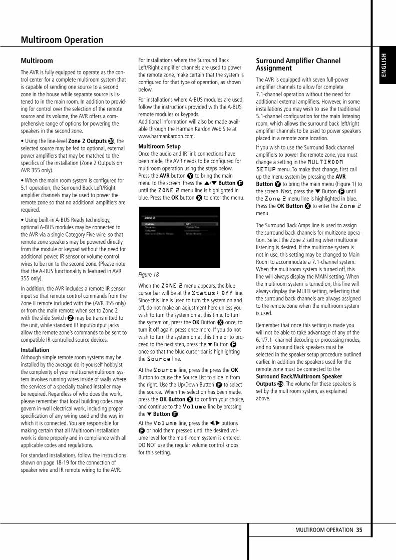
MULTIROOM OPERATION 35
Multiroom Operation
Multiroom
The AVR is fully equipped to operate as the con-trol center for a complete multiroom system thatis capable of sending one source to a secondzone in the house while separate source is lis-tened to in the main room. In addition to provid-ing for control over the selection of the remotesource and its volume, the AVR offers a com-prehensive range of options for powering thespeakers in the second zone.
• Using the line-level Zone 2 Outputs&, theselected source may be fed to optional, externalpower amplifiers that may be matched to thespecifics of the installation (Zone 2 Outputs onAVR 355 only).
• When the main room system is configured for5.1 operation, the Surround Back Left/Rightamplifier channels may be used to power theremote zone so that no additional amplifiers arerequired.
• Using built-in A-BUS Ready technology,optional A-BUS modules may be connected tothe AVR via a single Category Five wire, so thatremote zone speakers may be powered directlyfrom the module or keypad without the need foradditional power, IR sensor or volume controlwires to be run to the second zone. (Please notethat the A-BUS functionality is featured in AVR355 only).
In addition, the AVR includes a remote IR sensorinput so that remote control commands from theZone II remote included with the (AVR 355 only)or from the main remote when set to Zone 2with the slide SwitchZ may be transmitted tothe unit, while standard IR input/output jacksallow the remote zone’s commands to be sent tocompatible IR-controlled source devices.
InstallationAlthough simple remote room systems may beinstalled by the average do-it-yourself hobbyist,the complexity of your multizone/multiroom sys-tem involves running wires inside of walls wherethe services of a specially trained installer maybe required. Regardless of who does the work,please remember that local building codes maygovern in-wall electrical work, including properspecification of any wiring used and the way inwhich it is connected. You are responsible formaking certain that all Multiroom installationwork is done properly and in compliance with allapplicable codes and regulations.
For standard installations, follow the instructionsshown on page 18-19 for the connection ofspeaker wire and IR remote wiring to the AVR.
For installations where the Surround BackLeft/Right amplifier channels are used to powerthe remote zone, make certain that the system isconfigured for that type of operation, as shownbelow.
For installations where A-BUS modules are used,follow the instructions provided with the A-BUSremote modules or keypads.Additional information will also be made avail-able through the Harman KardonWeb Site atwww.harmankardon.com.
Multiroom SetupOnce the audio and IR link connections havebeen made, the AVR needs to be configured formultiroom operation using the steps below.Press the AVR buttonY to bring the mainmenu to the screen. Press the ⁄/¤ Button Funtil the ZONE 2 menu line is highlighted inblue. Press the OK buttonX to enter the menu.
Figure 18
When the ZONE 2 menu appears, the bluecursor bar will be at the Status: Off line.Since this line is used to turn the system on andoff, do not make an adjustment here unless youwish to turn the system on at this time. To turnthe system on, press the OK ButtonX once, toturn it off again, press once more. If you do notwish to turn the system on at this time or to pro-ceed to the next step, press the ¤ ButtonFonce so that the blue cursor bar is highlightingthe Source line.
At the Source line, press the press the OKButton to cause the Source List to slide in fromthe right. Use the Up/Down ButtonF to selectthe source..When the selection has been made,press the OK Button X to confirm your choice,and continue to the Volume line by pressingthe ¤ Button F.
At the Volume line, press the ‹ /› buttonsF or hold them pressed until the desired vol-ume level for the multi-room system is entered.DO NOT use the regular volume control knobsfor this setting.
Surround Amplifier ChannelAssignment
The AVR is equipped with seven full-poweramplifier channels to allow for complete7.1-channel operation without the need foradditional external amplifiers. However, in someinstallations you may wish to use the traditional5.1-channel configuration for the main listeningroom, which allows the surround back left/rightamplifier channels to be used to power speakersplaced in a remote zone location.
If you wish to use the Surround Back channelamplifiers to power the remote zone, you mustchange a setting in the MULTIROOMSETUP menu. To make that change, first callup the menu system by pressing the AVRButton Y to bring the main menu (Figure 1) tothe screen. Next, press the ¤ ButtonF untilthe Zone 2 menu line is highlighted in blue.Press the OK Button X to enter the Zone 2menu.
The Surround Back Amps line is used to assignthe surround back channels for multizone opera-tion. Select the Zone 2 setting when multizonelistening is desired. If the multizone system isnot in use, this setting may be changed to MainRoom to accommodate a 7.1-channel system.When the multiroom system is turned off, thisline will always display the MAIN setting.Whenthe multiroom system is turned on, this line willalways display the MULTI setting, reflecting thatthe surround back channels are always assignedto the remote zone when the multiroom systemis used.
Remember that once this setting is made youwill not be able to take advantage of any of the6.1/7.1- channel decoding or processing modes,and no Surround Back speakers must beselected in the speaker setup procedure outlinedearlier. In addition the speakers used for theremote zone must be connected to theSurround Back/Multiroom SpeakerOutputs. The volume for these speakers isset by the multiroom system, as explainedabove.
ENGLI
SH

36 MULTIROOM OPERATION
Multiroom OperationTo operate the multizone system using theremote, slide the Zone Select Switch at the bot-tom of the remote to the “2” position or, alter-natively use the Zone 2 Remote Control (AVR355 only). Press a Source Selector to select asource input for the remote zone.
Adjusting the volume or mute controls will onlyaffect the volume in the remote zone. The on-screen menu functions will not be operative. Theremote will operate source devices that havebeen programmed into it as explained in theInitial Setup section.
If the Remote IR Output jack on the AVRis connected to an IR Input jack on compatibleHarman Kardon audio components such as CD,DVD or cassette players, the transport functionsof those machines may also be controlled usingthe Transport Controls HE on eitherremote control.
NOTE: When the tuner is selected as the sourcefor Zone 2, any change to the frequency or pre-set will also change the station being listened toin the main room, if the tuner is in use there.Similarly, if someone in the main room changesthe station, the change will also impact theremote room.
When Zone 2 is turned on, the input selectedusing the Zone 2 Menu will be fed to the Zone 2Output jacks& on the rear panel as well as theA-BUS Jack', (AVR 355 only).The volume will be as set in the same menu,although it may also be adjusted using anoptional IR sensor and the Zone II remote in theremote location or on the optional audio poweramplifier connected to the Zone 2 Output jacks&.
Although changes to the input source or Zone 2volume will normally be made using an IR sensorin the remote room that is connected to theAVR, it is also possible to change those settingsfrom the main listening room. This is useful forsituations where some or all of the remoterooms do not have an IR sensor, or to takecontrol over the remote room without actuallybeing in that room.
Once Zone 2 is turned on, it will remain on evenif the AVR is placed in the Standby mode in themain room by pressing the Power Off ButtonB or the System Power Control 2 on thefront panel. To turn off the multiroom systemfrom the main listening room, when the AVR ison, slide the Zone Select Switch Z on theRemote Control to Zone 2 (or, alternatively, usethe Zone 2 Remote Control that comes with theAVR 355 only), and press the Off Button B.
Even when the AVR is turned off (to Standbymode) and the multiroom system is turned offtoo, the multiroom system may be turned on atany time by pressing the ON ButtonA whilethe Zone Select Button is set to Zone 2.
NOTE: Only analog audio sources are availableto the multizone system. To hear digital devices,such as a CD player, in the remote zone, followthese steps:
1. In addition to a digital audio connection,connect the source device’s analog audiooutputs to any available analog audio inputson the AVR, noting in Table AA in theappendix which set of inputs was used.
2. In the Setup Source menu, leave the AudioSource setting at the digital audio input.However, scroll down to the Zone 2 Audiosetting and select the analog audio sourceused in step 1.
Multiroom Operation

ADVANCED FEATURES 37
ENGLI
SH
Video Adjustments
Video Adjustments
The AVR 255/AVR 355 includes sophisticatedDCDi by Faroudja video processing that deliversenhanced video quality, even for older analogvideo source components, as well as upgradedon-screen displays.When upscaling videomaterials from a lower resolution to a higherone (the AVR 255/AVR 355 upscales to amaximum of 1080p), the processor is addingpixels to the original image. Sometimes whenconverting interlaced video (displays all oddrows then all even rows of the frame) toprogressive-scan video (displays all rows atonce) and increasing the resolution, theinterpolation of new pixels can cause jagginess,or a staircase effect, at edge transitions, such asthe stripes in an American flag. Faroudjaengineers developed the DCDi (DirectionalCorrelational Deinterlacing) algorithm to ensurethat the additional pixels follow the edge,virtually eliminating the jagginess and enhancingupscaled images.
Thanks to the “Torino” video processing chip,on-screen graphics may be generated in highdefinition, and blended with the incoming video.This not only delivers crisp, clear informationmessages, it allows you to continue to watch aprogram while making system adjustments.
Video Modes
After you have adjusted the picture settings onyour video display, additional adjustments maybe made to the AVR, if necessary, to furtherimprove the picture. Access these settings fromthe Video Modes menu. Press the Video ModesButton on the front panel or remote, and thescreen shown in Figure 19 will appear. The menumay also be accessed from the Setup Sourcemenu by pressing the Info Settings Button andselecting the Video Modes line.
Figure 19 – Video Modes Menu
Video Mode: The default setting of ProcessorOff passes the video signal through to thedisplay without any processing. Select one ofthese processing options to optimize the picturefor the current program by applying adjustmentsto the brightness, contrast, color and sharpness:
• Sports: For sporting events.
• Nature: For programs shot outdoors, in anatural setting.
• Movie: For movies and many televisionbroadcasts.
• Custom: Allows manual adjustment of thepicture settings. The Brightness, Contrast,Color and Sharpness settings will appear onscreen as sliders with values ranging from 0 to100. The default setting for each adjustment is50. Use theM/N Buttons to change eachsetting’s value.
Picture Adjust: Use this setting to change theaspect ratio of the displayed image.
When displaying widescreen (16:9) images on afull screen (4:3) device, letterbox format will beused, in which black bars may appear above andbelow the image (pillarboxing).
When displaying full screen images on awidescreen device, black or gray bars mayappear to the left and right of the image.
Some displays, especially plasma and CRTmonitors, may suffer from “burn-in” when thesame image, such as the horizontal or verticalbars, is left on screen for a long period of time.Use this setting to adjust the picture so that itfills the display’s screen. The options are:
• Auto Fit: The AVR automatically adjusts theimage as required tofit the display’s capabilities.
• Height Fit: Adjusts the image to eliminateany bars above or belowit. Bars may remain at the sides.
• Width Fit: Adjusts the image to eliminate anybars on the sides.Bars may remain above and below the image.
• Zoom 1x: Displays the image as receivedfrom the source. If the image is in the 4:3aspect ratio, on widescreen displays pillarboxformat may be used. If the image is in the16:9 aspect ratio, on full screen (4:3) displaysletterbox format may be used.
• Zoom 2x: Stretches the image evenly tocompletely fill the screen. The outer portions ofthe image may be cropped.
Feel free to experiment with this setting for eachsource until you find a pleasing display formatfor each program.
Advanced Video Settings: Press theN or OKButton to display the Advanced Video Modessubmenu (see Figure 20).
Figure 20 – Advanced Video Modes Menu
Noise Reduction: To reduce signal noise,choose between LOW, MEDIUM, HIGH or OFFwith the OK buttonX. It is advisable to use aslow a step as possible, as high levels of NoiseReduction may impair other aspects of theimage.
MPEG Noise Reduction: This setting isdesigned to address two specific types of videodistortion, mosquito noise and blocking artifacts.If you see haziness or shimmering around theedges of objects or the scrolling credits in a film,or if the image appears to “pixellate” intoblocks, change the MPEG Noise Reductionsetting from its default of Off to the Low,Medium or High setting to improve the picture.
Cross Color Suppressor: Turn this setting onto remove cross color artifacts, which can occurwhen high-frequency luminance (brightness)signals are misinterpreted as chroma (color)signals, which can cause unwanted flickering,flashing colors or rainbow patterns.
Film Mode Detect:While normally left off,turn this setting on to compensate for authoringerrors in the process of converting film programsto video.
Return to main Video Modes Menu bypressing Back/Exit
Brightness: This control adjusts the level atwhich black is delivered.We recommend leavingit at its factory setting, although there is noharm in experimenting if you are using a testsignal.
Contrast: This control adjusts the differencebetween black and white in the picture.Werecommend leaving it at its factory setting,although there is no harm in experimenting ifyou are using a test signal.

Color: This control adjusts the hue of the colorsin the picture, and may be set between 0 and100. Select a setting in which people andobjects on screen look natural. There is no“recommended” setting, and no harm inexperimenting.
Sharpness: You may adjust the Sharpnesssetting from 0 to 100.We recommend leavingthis setting as low as possible, as contrary towhat you might expect, a less sharp image canappear clearer on screen. In addition, increasingthe Sharpness requires additional videoprocessing, which may lead to loss of sync withthe audio or visual artifacts. However, there is noharm in experimenting with this setting.
Audio Effects
Depending on the specific characteristics of yourlistening room, you may wish to adjust some ofthe audio settings, such as tone controls, toimprove performance. Access these settings fromthe Audio Effects menu. Press the Audio EffectsButton on the front panel or remote, and thescreen shown in Figure 21 will appear. The menumay also be accessed from the Setup Sourcemenu by pressing the Info Settings Button andselecting the Audio Effects line.
NOTE: The settings in the Audio Effects menuaffect each source independently.
Figure 21 – Audio Effects Menu
Tone Control: This setting determines whetherthe treble and bass controls are active.When it’soff, the tone controls are “flat”, with nochanges.When it’s on, the bass and treblefrequencies are boosted or cut depending uponthe tone-control settings.When an analog audiosource is in use and the 2-Channel Stereosurround mode is selected, setting the ToneControl to “Off” places the unit in analogbypass mode, with no digital processing of theanalog signal.
Treble: Boost or cut the high frequencies by upto 10dB by using theM/N Buttons to changethe temperature bar setting. The default settingis 0dB, at the center of the temperature bar.
Bass: Boost or cut the low frequencies by up to10dB by using theM/N Buttons to change thetemperature bar setting. The default setting is0dB, at the center of the temperature bar.
LFE Trim: lets you reduce the output to theseparate subwoofer channel by up to 10dB in1dB steps, if the general level to the sub set upin the Speaker Setup Menus seems too loud fora particular Source.
Night Mode: This setting is used with speciallyencoded Dolby Digital programs to compress thesignal so that louder passages do not disturbothers, while dialogue remains intelligible.
• Off: For normal listening.
• Half: Applies moderate compression.
• Full: Applies the most compression.
When you have finished making adjustments inthe Audio Effects menu, press the Audio EffectsButton or the Back/Exit Button to clear thescreen.
Advanced Features
The AVR 255/AVR 355 is equipped with anumber of advanced features that add extraflexibility to the unit’s operation.While it is notnecessary to use these features to operate theunit, they provide additional options that youmay wish to use.
System Settings
The AVR 255/AVR 355 offers system settingsthat allow you to make the receiver easier to userather than directly affecting performance. Thesesettings may be accessed from the SystemSettings menu, which is selectedby pressing the AVR Button and navigating tothe System line. Press the OK Button to displaythe System Settings menu. See Figure 22.
Figure 22 – Systems Settings Screen
Front Panel Dimmer: Some people find thefront-panel messages distracting while watchinga movie. The AVR 255/AVR 355 allows you todim the front-panel lighting or turn it offaltogether.When the display is partly or fullydimmed, it will return to full brightness for fiveseconds whenever a command is entered, andthen it will dim again. Select On 100% for fullbrightness, dim to 50% or 25% of fullbrightness or select Off to fully darken thedisplay. The light inside the Volume Control willgo out when the display is partly or fullydimmed, but the Power Indicator will alwaysremain lit to remind you that the AVR is poweredon.
General AVR Settings
Volume Units: Select whether volume isdisplayed in the conventional decibel scale or ona numeric scale from 0 to 100.When the decibelscale is used, 0dB is the maximum volume, withlower volumes measured as negative values.
Volume Default and Volume Default Level:These two settings are used together to programa volume level the AVR will always switch towhen turned on. This feature avoids discomfortfor listeners in case the last user turned thevolume very high.
Turn Volume Default on, and then set theVolume Default Level to the desired turn-onvolume.
Unit of Measure: This setting only affects thespeaker-distance settings when performingManual Speaker Setup. Select between metersand feet.
iPod Charging: (AVR 355 only).When dockedin a Bridge2 Docking Station, plugged into theBridge Connector on the rear panel, you mayselect that your iPod is being charged all thetime, or that no charging is taking place.
Language: Select the preferred language forthe AVR’s on-screen menus and displays:English, French, Spanish, German, Italian orRussian.
HDMI Audio to TV: This setting determineswhether audio signals received through any ofthe HDMI Inputs are passed through the HDMIOutput to the video display. In normal operation,leave this setting Off, as audio will be playedthrough the AVR rather than the video display’sbuilt-in speakers. However, sometimes you maywish to use the TV by itself, without using thecomplete home theater system. For thoseoccasions change this setting to On. You mayalways mute the TV’s speakers when using theAVR for audio.
Audio Effects Advanced Features
38 ADVANCED FEATURES
Resolution to Display: Select the highestresolution that your TV can show. If you useHDMI, resolution selection happensautomatically. If you use analog signals, youmust choose the proper resolution. Note: if youchoose a resolution that is higher than yourscreen can show, the picture disappears. In thiscase, wait for approx. 10 seconds, as the AVRreturns to the previous resolution if the new oneis not confirmed within this time. Defaultresolution is 576i, which is the maximum thatcan be transmitted by the simplest videoconnection, Composite/CVBS.
Menu Appearance
OSD Transparency: This setting allows you toselect whether video programs will be visiblewhen the menu system is in use. Select Normalfor a fully-transparent background, Medium forthe menu background to be partially visible orOpaque to block the view of any video programswhile the menus are on screen.
Volume Status Messages:When the AVR isturned on, the volume is adjusted or the sourceis changed, or if a change in the input signal isdetected, a status message will be displayed onscreen. Use this setting to select how long themessage remains visible. The setting varies from2 to 10 seconds, with a default of 3 seconds.
Menus: Some menu settings only remain ineffect during the current listening session,including the settings in the Surround Modes,Video Modes and Audio Effects menus. Thissetting governs how long these menus willremain visible after your last adjustment, varyingfrom 5 seconds to 5 minutes, or no time-out (themenu does not disappear until you close it), witha default of 5 seconds.
Setup and Slide-In Menus: This settingdetermines how long the setup menus (MainMenu, Speaker Setup Menu, Zone 2 Menu, allslide-in menus) remain visible after your lastadjustment. Select a timeout period of 5, 10 or15 (the default) minutes, or no timeout, whichleaves the menus on screen until you manuallyclear them.We recommend setting some timeoutperiod to avoid the possibility of burn-in damageto plasma or CRT displays.
Screen Saver: Use this setting to program atimeout period for no activity (with no menusdisplayed) before the AVR’s built-in screen saverbegins. Select a period of 5 (the default), 10 or20 minutes, or turn off the screen saver.Werecommend setting some timeout period toavoid the possibility of burn-in damage toplasma or CRT displays.
Default Surround Mode
In normal operation, when the AVR senses aDolby Digital or DTS digital audio data stream, itwill automatically switch the appropriate defaultsurround mode, with the AVR responding to thedata flags that are encoded on the DVD disc orin the digital video broadcast. In most cases, thisis the correct mode, but you may have aparticular preference for the mode you wish tohear when Dolby Digital or DTS is present. TheAVR allows you to set the unit so that it willeither respond to the default or switch to yourdesired mode.
If you wish to leave the default so that the modechoice encoded in the disc is always used, nofurther action is needed. Simply leave the settingat the factory default of ON.
To set the unit so that it responds to the last sur-round mode used when a Dolby Digital or DTSsource is playing, press the ⁄/¤ Buttons Dso that the blue cursor bar is highlighting theDefault Surround Mode line. Pressthe OK Button F, followed by the‹ /› Buttons E so that OFF appears,and the setting will change. Press the OKButton F again to confirm the new setting.The unit will now use the last mode, not thedisc’s default for the two digitally encoded datastreams.
This setting does not apply to standard PCMdigital inputs or to analog sources. In thosecases, the unit will always apply the surround orprocessing mode that was last used for thatinput.
If you wish to make other adjustments, press the⁄/¤ Buttons D until the blue cursor bar ishighlighting the desired setting. If you have noother adjustments to make, press the OSDButton L to exit the menu system.
Advanced Features
ENGLI
SH
ADVANCED FEATURES 39

Tuner Operation
To select the built-in tuner:
1. Press the Source List Button on the frontpanel and use theK/L Buttons to scrollthrough the source list. The last-used band (AMor FM) will be active.
2. Press the Radio Source Selector on theremote. Press this button again to switch bands(AM or FM). A screen similar to the one shownin Figure 23 will appear, with the band indicatedin the middle of the screen.The "XM Radio" thatappears as an option in the Source Menu can bedisregarded, as it is used in the US version only.The Menu system skips over this option.
Figure 23 – FM Radio
Use theK/L Buttons to tune a station. Thefrequencies will be displayed in the front paneland graphically on screen.
The AVR defaults to automatic tuning, meaningeach press of theK/L Buttons scans throughall frequencies until a station with acceptablesignal strength is found. To switch to manualtuning, in which each press of theK/LButtons steps through a single frequencyincrement (0.05MHz for FM, or 9kHz for AM),press the Menu Button. The Mode line will behighlighted, and each press of the OK Buttontoggles between automatic and manual tuningmodes as well as Stereo (in Automatic Mode)and Mono (in Manual Mode).
You may also enter the frequency of a radiostation directly. In the Slide-In Menu opened bypressing the Menu ButtonM with the unit inFM-Mode, select Direct Entry (appearing justabove the preset channel listing) with the ArrowButtons, then press OK. The Main InformationDisplay now shows DIRECT IN as a slide-ininformation, and a * moves back and forth toindicate that the AVR is ready for Direct Entry ofthe frequency. You must begin entering numberswithin 10 seconds. Otherwise, the AVR reverts toprevious mode. Now press the frequency digits.If you begin with "1" to enter a stationfrequency in the 100-range, the first "1" isautomatically registered as "10", after whichyou may enter the third main digit and the twodecimal digits. Example: 96,50 is entered as itappears: Nine, Six, Five, Zero. 102,65 is enteredlike this: One, Two, Six, Five.
A total of 30 stations (AM and FM together)may be stored as presets.When the desiredstation has been tuned, press the OK Button,and two dashes will flash in the front-paneldisplay. Use the Numeric Keys to enter thedesired preset number, and confirm with the OKButton. If the preset number is higher than 9,press the 0-Button on the RemoteK first toaccess two-digit numbers. If you do not pressthis button first, you can only enter single-digitnumbers..
To tune a preset station, press theM/N Buttonsor press the Menu Button to view the list ofprogrammed presets and scroll to the desiredselection. Press the OK Button to tune thestation. You may also enter the preset numberusing the Numeric Keys. For presets 10 through30, press the Zero ButtonK first to show ablinking 0 in the Information Display, then enterthe two digits. For example, enter preset 17 bypressing 0, then 1, then 7. If you want to enteranother two-digit preset, you must press 0 againfirst.
RDS Operation
The AVR 255/AVR 355 is equipped with RDS(Radio Data System), which brings a wide rangeof information to FM radio. Now in use in manycountries, RDS is a system for transmitting sta-tion call signs or network information, a descrip-tion of station program type, text messagesabout the station or specifics of a musical selec-tion, and the correct time.
As more FM stations become equipped with RDScapabilities, the AVR will serve as an easy-to-usecenter for both information and entertainment.This section will help you take maximumadvantage of the RDS system.
RDS TuningWhen an FM station is tuned in and it containsRDS data, the AVR will automatically display thestation’s call sign or other program service in theMain Information Display # and on the tvscreen if this is on.
RDS Display OptionsThe RDS system is capable of transmitting awide variety of information in addition to theinitial station call sign that appears when astation is first tuned. In normal RDS operationthe display will indicate the station name,broadcast network or call letters. Pressing thePlay ButtonE on the Remote enables you tocycle through the various data types in the fol-lowing sequence:
• The station’s call letters (PS) (with some pri-vate stations other information too).
• The station’s frequency (FREQ MODE),which is always shown on the TV On-ScreenDisplay, is shown in the Main InformationDisplay.
40 TUNER OPERATION

Tuner Operation
• The Program Type (PTY) as shown in the listbelow.
NOTE: Many stations do not transmit a specificPTY. The display will show NONE, when such astation is selected and PTY is active.
• A “text” message (Radiotext, RT) containingspecial information from the broadcast station.Note that this message may scroll across thedisplay to permit messages longer than the eightpositions in the display. Radiotext is not shownon the TV On-Screen Display.
• The current time of day (CT). Note that it maytake up to two minutes for the time to appear,in that time the letters CT are shown in theinformation display when CT is selected. Pleasenote that the accuracy of the time data isdependent on the radio station, not the AVR.
Some RDS stations may not include some ofthese additional features. If the data requiredfor the selected mode is not being transmitted,the Main Information Display Ò will showa NO TYPE, NO TEXT or NO TIMEmessage after the individual time out.
In any FM mode the RDS function requires astrong enough signal for proper operation.
Program Search (PTY)An important feature of RDS is its capability ofencoding broadcasts with Program Type (PTY)codes that indicate the type of material beingbroadcast. The following list shows theabbreviations used to indicate each PTY, alongwith an explanation of the PTY:
• NEWS: News
• AFFAIRS: Current Affairs
• INFO: Infomation
• SPORT: Sports
• EDUCATE: Educational
• DRAMA: Drama
• CULTURE: Culture
• SCIENCE: Sciencek
• VARIED: Varied Speech Programs
• POPM: Popular Music
• ROCKM: Rock Music
• M.O.R.M.: Middle-of-the-Road Music
• LIGHTM: Classical Music
• CLASSICS: Serious Classical Music
• OTHERM: Other Music
• WEATHER: Weather Information
• FINANCE: Financial Programs
• CHILDREN: Children’s Programs
• SOCIAL A: Social Affairs Programs
• RELIGION: Religious Broadcasts
• PHONE IN: Phone-In Programs
• TRAVEL: Travel and Touring
• LEISURE: Leisure and Hobby
• JAZZ: Jazz Music
• COUNTRY: Country Music
• NATIONAL: National Music
• OLDIES: Oldies Music
• FOLK M: Folk Music
• DOCUMENT: Documentary Programs
• TEST: Emergency Test
• ALARM: Emergency Broadcast Information
You may search for a specific Program Type(PTY) by following these steps:
1. Press the Play buttonE until thecurrent PTY is shown in the Main InformationDisplay #.
2.While the PTY is shown, press the CH/PageUp/DownI or theM/N ButtonsF or holdthem pressed to scroll through the list of avail-able PTY types, as shown above starting withthe PTY currently received.
3. Press either of theK/L ButtonsF. Thetuner begins to scan the FM band upwards ordownwards for the first station that has RDSdata that matches the desired selection, andacceptable signal strength for quality reception.
4. The tuner will make up to one complete scanof the entire FM band for the next station thatmatches the desired PTY type and has accept-able reception quality. If no such station isfound, the display will read NONE for someseconds and the tuner will return to the last FMstation in use before the search.
ENGLI
SH
TUNER OPERATION 41

The AVR 255/AVR 355 is equipped with a pow-erful remote control that will control not only thereceiver’s functions, but also most popularbrands of audio and video equipment, includingCD players, TV sets, cable boxes, VCRs, satellitereceivers and other home-theater equipment.Once the AVR’s remote is programmed with thecodes for the products you own, it is possible toeliminate most other remotes and replace themwith the convenience of a single universalremote control.
Programming the Remotewith CodesAs shipped from the factory, the remote is fullyprogrammed for all AVR functions, as well asthose of most Harman Kardon CD changers, DVDplayers, CD players and cassette decks as well asthe navigation controls for the Apple iPod. Inaddition, by following one of the methods below,you may program the remote to operate a widerange of devices from other manufacturers.
Direct Code EntryThis method is the easiest way to program yourremote to work with different products.
1. Use the tables in the separate setup-codeguide to determine the three-digit code or codesthat match both the product type (e.g., VCR, TV),and the specific brand name. If there is morethan one number for a brand, make note of thedifferent choices.
2. Turn on the unit you wish to program into theAVR remote.
3. Press and hold the Input Selector c forthe type of product to be entered (e.g., DVD, TV)more than 3 seconds, until it lights up, thenrelease it. It is important that you begin the nextstep within 20 seconds.
4. If the unit you wish to program into theAVR remote has a remotable Power on/off func-tion, follow these steps:
a. Point the AVR’s remote towards the unit to beprogrammed, and enter the first three-digitcode number using the Numeric buttons k.If the unit being programmed turns off, the cor-rect code has been entered. Press the InputSelector c again, and note that the red lightunder the Input Selector will flash threetimes before going dark to confirm the entry.
b. If the product to be programmed does NOTturn off, continue to enter the three-digit codenumbers until the equipment turns off. At thispoint, the correct code has been entered.Press the Input Selector c again and notethat the red light under the Input Selectorwill flash three times before going dark toconfirm the entry.
5. If the Power function of the unit to be pro-grammed cannot be remoted, follow these steps(max. 20 seconds after step 3 above, or else step3 must be repeated first):
a. Enter the first three-digit code number usingthe Numeric buttons k and press the InputSelector c again. Press the remote buttonof any transport function remotable with theunit, e.g. Pause or Play fl e. If the unitbeing programmed starts that function, thecorrect code has been entered.
b. If the unit does not start the function whosebutton was pressed, repeat steps 3 and 5aabove with the next three-digit code numberlisted in the setup code table for that brandand product type, until the unit reacts properlyon the transport function transmitted.
6. Try all of the functions on the remote to makecertain that the product operates properly. Keepin mind that many manufacturers use a numberof different combinations of codes, so it is agood idea to make certain that not only does thePower control work, but that the volume, chan-nel and transport controls work as they should.If functions do not work properly, you may needto use a different remote code.
7. If the unit does not react to any codeentered, if the code for your product does notappear in the tables in the separate setup-codeguide, or if not all functions operate properly,try programming the remote with the AutoSearch Method.
Auto-Search MethodIf the unit you wish to include in the AVR’sremote is not listed in the code tables in theseparate setup-code guide or if the code doesnot seem to operate properly, you may wish toprogram the correct code using the Auto Searchmethod that follows. Note that the Auto Searchmethod works only with units whose Powerfunctions can be remoted:
1. Turn on the product that you wish to includein the AVR remote.
2. Press and hold the Input Selector c forthe type of product to be entered (e.g., DVD, TV)more than 3 seconds, until it lights up, thenrelease it. It is important that you begin the nextstep within 20 seconds.
3. To find out if the code for your unit is pre-pro-grammed, point the AVR remote towards the unitto be programmed, and press and hold the ⁄
button f. Each press of the button sends thePower signal for one setup code number, andkeeping the button down sends a series of codesfrom the remote’s built-in data base, with eachflash of the red light under the Input Selectorc indicating that a code has been sent.Whenthe device to be programmed turnsoff,immediately release the ⁄ buttonf. Notethat it may take one minute or more until theright code is found and the unit turns off.
4.When the ⁄ button was not released in timeafter the unit turned off, the proper code will be”overrun”. That’s why a function test should bemade: Turn the unit on again and, while theInput Selector c still lights red, press the ⁄
buttonf once, then the ¤ button f once too.When the unit turns off, the right code wasfound, when not, the code was ”overrun”. To re-find the correct code, while the Input Selectorc still lights red, press (not hold pressed) the ¤
button f repeatedly to step backwards throughthe codes available and observe the reaction ofthe unit at each press. As soon as the unit turnsoff the correct code is found.
5. Press the Input Selector c again, and notethat the red light will flash three times beforegoing dark to confirm the entry.
6. Try all of the functions on the remote to makecertain that the product operates. Keep in mindthat many manufacturers use a number of differ-ent combinations of codes, and it is a good ideato make certain that not only the Power controlworks, but the volume, channel and transportcontrols, as appropriate. If all functions do notwork properly, you may need to Auto-Search fora different code, or enter a code via the DirectCode Entry method.
Code ReadoutWhen the code has been entered using the AutoSearch method, it is always a good idea to findout the exact code so that it may be easily reen-tered if necessary. You may also read the codesto verify which device has been programmed toa specific Control Selector button.
1. Press and hold the Input Selector c forthe device you wish to find the code for morethan 3 seconds, until it lights up, then release it.Release the button and begin the next stepwithin 20 seconds.
2. Press the OK button x. The Input SelectorButton c will then blink green in a sequencethat corresponds to the three-digit code, with aone-second pause between each digit. Countthe number of blinks between each pause todetermine the digit of the code. One blink is thenumber 1, two blinks is the number 2, and soforth. Note that a rapid "Flick" (which is shorterthan a blink), is used to indicate a “0.”
Programming the Remote
42 PROGRAMMING THE REMOTE

Programming the Remote
Example: One blink, followed by a one-secondpause, followed by six blinks, followed by a one-second pause, followed by four blinks indicatesthat the code has been set to 164.
For future reference enter the Setup Codes forthe equipment in your system here:
DVD ____________ CD ________________
VID1/VCR ________VID3/TV __________
VID2/CBL/SAT ______________________
TAPE ______________________________
VID4 ______________________________
Learning Codes from a Remote(AVR 355 Remote only)
In addition to using codes from the remote’sinternal code library, the AVR 355’s remote isable to “learn” codes from remotes that may notbe in the code library. In addition, you may usethis function to “learn over” the codes from apreprogrammed device to add functions notincluded in the preprogrammed codes. To learnor transfer codes from an IR remote to theAVR 355’s remote, follow these steps:
1. Place the front of the original remote with thecode being sent so that it is facing the IRTransmitter Window w on the AVR 355remote “head-to-head.” The remotes should bebetween 2 and 4 cm apart.
2. Select the button on the remote that you wishto use as the device selector for the codes aboutto be entered. This must be any of the InputSelectors 4 or the AVR Selector 5. Notethat when new codes are learned with the AVRSelector 5, they may no longer control theAVR 355.
3. Press the Input Selector cy buttonunder which you wish to learn one or more but-tons. Now press the Learn Button (T) for 3 sec-onds. The Input Button that you pressed lastlights up. It is important that you begin the nextstep within 25 seconds.
4. Press the button on the AVR 355 remote thatyou wish to program. Note that the Input Buttonblinks once.
Important Note: The following buttons arelearnable: DEVICE POWER ON/OFF, 0~9, LAST,BACK/EXIT, MENU, UP, DOWN, LEFT, RIGHT, OK,DISC MENU, RED, GREEN, YELLOW, BLUE,CHANNEL UP/DOWN, VOLUME UP/DOWN,MUTE, PREVIOUS, NEXT, FF, REW, PLAY, STOP,RECORD (Total 37 keys). These buttons can beprogrammed differently in each DEVICE mode. Ifyou try to select a non-learnable button, theInput Button blinks rapidly.
5. Place the two remotes facing each other at 2-4cm distance. Now press and hold the button onthe original remote that you wish to “teach”into the AVR 355 remote.When the Input Buttonon the AVR 355 blinks 3 times, the code hasbeen learned.
6. Repeat steps 4 though 5 for each button onthe source remote that you wish to transfer tothe AVR 355 remote.
7. Once all codes have been transferred from theoriginal source remote to the AVR 355 remote,press the Learn button t. The Input Buttonblinks 3 times and the light extinguishes to indi-cate that Learn mode is turned off.
8. Repeat Steps 1 through 7 for any additionalremotes you wish to “teach” into the AVR 355Remote.
Erasing Learned Codes
The AVR 355’s remote allows you to remove orerase the code learned into a single button for asingle device, to remove or erase all the codesthat have been learned for a single device, or toerase all commands that have been learned to alldevices.
To erase a single learned code fromwithin a single device’s settings, followthese steps:1. Press and release the Input Selector cywithin which the individual button to be erasedhas been programmed.
2. Press the Learn Button t for 3 seconds. TheInput Button pressed before lights up.
3. Press and release the Input Selector cyagain for the device within which the individualbutton to be erased has been programmed.
4. Press the 7 button k three times.
5. Press and release the individual button forwhich the code is to be erased. The Input Buttonselected blinks 3 times.
6. To erase other buttons within the same device,press them as noted in Step 5.
7. Press the Learn Button t for 3 seconds. TheInput Button pressed before lights up.
To erase all codes within a single device,follow these steps:1. Press and release the Input Selector cyfor which you wish to erase the codes.
2.When the red LED under the Input Selectorturns red and the Program/SPL Indicator 2flashes amber, release the buttons.
3. Press and release the same Input Selectorcy again for the device whose codes you wishto erase.
4. Press the 8 button k three times.
5. Input Button selected blinks 3 times and extin-guishes.
To erase all codes that have been pro-grammed to all devices in the remote,follow these steps:1. Press the Learn button t for 3 seconds.
2. Press and release any Input Selector buttoncy.
3. Press the 9 button k three times.
4. The Input Button selected blinks 3 times andextinguishes.All buttons in all modes are nowreset to the original code set.
ENGLI
SH
PROGRAMMING THE REMOTE 43
Programming the Remote
Activity Programming (Macros)Activities enable you to easily repeat frequentlyused combinations of commands with the pressof a single button on the AVR’s remote control.Once programmed, an Activity will send out up to19 different remote codes in a pre-determinedsequential order enabling you to automate theprocess of turning on your system, changingdevices, or other common tasks. The AVR’sremote can store up to eleven separate activitycommand sequences, one that is associated withthe AVR Power On button a, and ten morethat are accessed by pressing the 0-9 Buttonsk.
1. To start programming an activity, press theActivity button n and one of the 0-9 buttonsk to be programmed or the AVR Power Onbutton a at the same time. Note that the latestselected Device LED will light red.
2. Enter the steps for the activity sequence bypressing the button for the actual commandstep. Although the activity may contain up to 19steps, each button press, including those used tochange devices, counts as a step. The DeviceLED will blink once to confirm each button pressas you enter commands.
• Remember to press the appropriate InputSelector button c before functions arechanged to another device. This is also neededfor the AVR Selector button y itself, as longas it’s not lit red and AVR functions shall beprogrammed.
3. When all the steps have been entered, pressthe Activity button n again to enter thecommands. The red light under the InputSelector cy will blink three times and thenturn off.
Note: It can take up to 10 seconds to send out19 commands from an Activity Button. Pleasecontinue to point the remote control at thedevice(s) until all the commands on the ActivityButton have been sent out. This will ensure thatall the commands are received by the device(s).
Example: Activity Button Programming.To program Activity Button “2” to send the fol-lowing commands: turn on the Audio receiver,turn on the TV, turn on a DVD, and turn on aSatellite receiver.Press the Activity Button “2” and the ACTIVITYbutton, simultaneously.Press the AVR device button(to change to theAVR mode)Press the AVR POWER ON button(to turn on theAudio receiver)Press the TV device button(to change to the TVmode)Press the DEVICE POWER ON button(to turn onthe TV)Press the DVD device button(to change to theDVD mode)Press the DEVICE POWER ON button(to turn onthe DVD)Press the SAT device button(to change to theSAT mode)Press the DEVICE POWER ON button(to turn onthe SAT receiver)10. Press the ACTIVITY button.After following these steps, each time you pressthe Activity Button n, followed by pressingthe "2" Button where the Activity is pro-grammed,, the remote will send all Power Oncommands.
The "2" Button only sends the programmedActivity when the Activity Button n ispressed first. Otherwise, Button "2" sends thenormal, numerical 2.
Erasing Activity ButtonsPress the Activity button n and the ActivityButton (0~9, or AVR POWER ON) that you wishto program, simultaneously. The Device LED willlight up.
Press the Activity button n again. The DeviceLED blinks three times.
Note: Any previously stored commands on anActivity Button will be erased when new com-mands are stored on the same Activity Button.
Programmed Device FunctionsOnce the AVR’s remote has been programmed forthe codes of other devices, press the appropriateInput Selector c to change the remote fromcontrol over the AVR to the additional product.When you press any of these buttons, it will brieflyflash in red to indicate that you have changed thedevice being controlled.
When operating a device other than the AVR, thecontrols may not correspond exactly to the func-tion printed on the remote or button. Some com-mands, such as the volume control, are the sameas they are with the AVR. Other buttons willchange their function so that they correspond toa secondary label on the remote. For example,the Sleep and Surround mode selector buttonsalso function as the Channel Up and ChannelDown buttons when operating most TV sets,VCRs or Sat-Receivers.
For some products, however, the function of aparticular button does not follow the commandprinted on the remote. In order to see whichfunction a button controls, consult the FunctionList tables printed on page 46-50. To use thosetables, first check the type of device beingcontrolled (e.g., TV, VCR). Next, look at theremote control illustration belonging to theFunction List. Note that each button has a num-ber on it.To find out what function a particular button hasfor a specific device, find the button number onthe Function List and then look in the column forthe device you are controlling. Most of the but-tons are fairly straightforward, as they performidentical functions for all devices, but some haveother functions for some devices.
44 PROGRAMMING THE REMOTE

Programming the Remote
Notes on Using the AVRRemote With Other Devices.• Manufacturers may use different code sets forthe same product category. For that reason, it isimportant that you check to see if the code setyou have entered operates as many controls aspossible. If it appears that only a few functionsoperate, check to see if another code set willwork with more buttons.
• Depending on the brand and product typeused the functions listed in the Function Listtables may not correspond with the function theunit reacts on the command. In these cases it’s agood idea to edit the reaction of the unit intothe corresponding line of the table or to set up aseparate list.
•When a button is pressed on the AVR remote,the red light under the Input Selector cyfor the product being operated should flashbriefly. If the Device Control Selector flashes forsome but not all buttons for a particularproduct, it does NOT indicate a problem with theremote, but rather that no function isprogrammed for the button being pushed.
Punch-Through Programming
The AVR 355/AVR 255 remote’s punch-throughfeature allows you to select one component forthe remote to operate, while simultaneously set-ting certain groups of controls to operate anoth-er component. For example, while using the AVRto control surround modes and other audio func-tions, you may operate the transport controls ofyour DVD player. Or while using the remote tocontrol video functions on your TV, you may useyour cable box to change channels.
To program punch-through control while operat-ing any device:
1. Press and hold the Source Selector (or AVRselector) for the main device the remote willbe operating. The Source Selector will light, godark and then light up again, indicating theremote is in Program mode and that you mayrelease the button.
2. Select the type of punch-through program-ming.a) To program channel control punch-through,press the Channel Up Button.b) To program transport control punch-through, press the Play Button.
3. Press the Source Selector for the device whosechannel or transport controls you would liketo be active while operating the device youselected in the first step. The Source Selectorwill flash to confirm the programming.
For example, if you wish to watch your TV whilechanging channels using your cable box, firstpress the TV Button until it lights. Then press theChannel Up Button, followed by the CBL/SATButton.
To undo punch-through programming, followthe same steps as above, but press the sameSource Selector in Steps 1 and 3.
NOTE: The remote always allows volume-controlpunchthrough, since the Volume and Mute con-trols are dedicated to the AVR.
Resetting the Remote MemoryAs you add components to your home-theatersystem, occasionally you may wish to totallyreprogram the remote control without theconfusion of any commands, activities or ”Punch-Through“ programming that you may have done.To do this, it is possible to reset the remote to theoriginal factory defaults and command codes byfollowing these steps. Note, however, that oncethe remote is reset, all commands or codes thatyou have entered will be erased and will need tobe re-entered:
1. Press the TV Device Button c and the "0"number Button k simultaneously. The TV buttonlights up.
2. Press the ”3“ button k three times.
3.After a number of seconds, depending on thenumber of commands that are programmed andneed erasing, all the Device Buttons c as well asthe AVR Button y blink 3 times to indicate thatthe remote has been reset to the factory settings.
ENGLI
SH
PROGRAMMING THE REMOTE 45
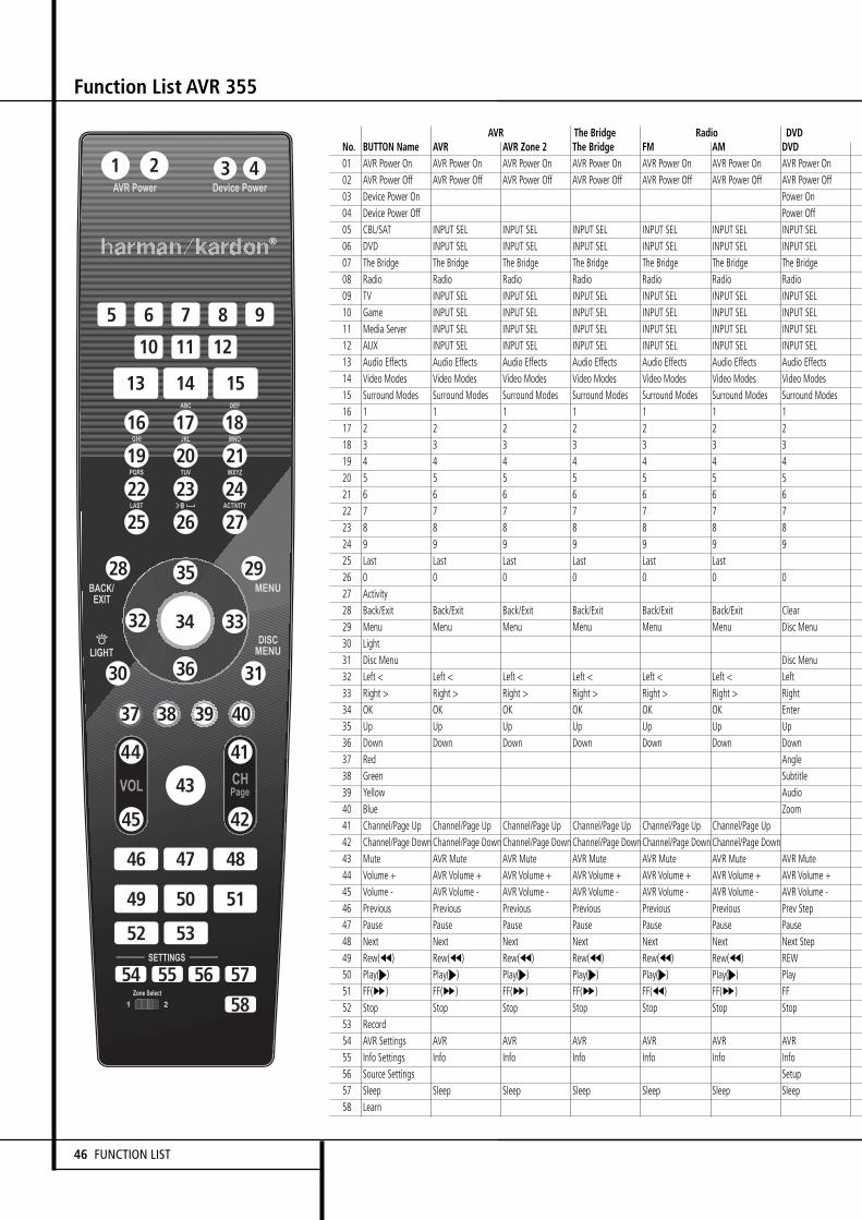
No. BUTTON Name AVR AVR Zone 2 The Bridge FM AM DVD01 AVR Power On AVR Power On AVR Power On AVR Power On AVR Power On AVR Power On AVR Power On02 AVR Power Off AVR Power Off AVR Power Off AVR Power Off AVR Power Off AVR Power Off AVR Power Off03 Device Power On Power On04 Device Power Off Power Off05 CBL/SAT INPUT SEL INPUT SEL INPUT SEL INPUT SEL INPUT SEL INPUT SEL06 DVD INPUT SEL INPUT SEL INPUT SEL INPUT SEL INPUT SEL INPUT SEL07 The Bridge The Bridge The Bridge The Bridge The Bridge The Bridge The Bridge08 Radio Radio Radio Radio Radio Radio Radio09 TV INPUT SEL INPUT SEL INPUT SEL INPUT SEL INPUT SEL INPUT SEL10 Game INPUT SEL INPUT SEL INPUT SEL INPUT SEL INPUT SEL INPUT SEL11 Media Server INPUT SEL INPUT SEL INPUT SEL INPUT SEL INPUT SEL INPUT SEL12 AUX INPUT SEL INPUT SEL INPUT SEL INPUT SEL INPUT SEL INPUT SEL13 Audio Effects Audio Effects Audio Effects Audio Effects Audio Effects Audio Effects Audio Effects14 Video Modes Video Modes Video Modes Video Modes Video Modes Video Modes Video Modes15 Surround Modes Surround Modes Surround Modes Surround Modes Surround Modes Surround Modes Surround Modes16 1 1 1 1 1 1 1 117 2 2 2 2 2 2 2 118 3 3 3 3 3 3 3 119 4 4 4 4 4 4 4 120 5 5 5 5 5 5 5 221 6 6 6 6 6 6 6 222 7 7 7 7 7 7 7 223 8 8 8 8 8 8 8 224 9 9 9 9 9 9 9 225 Last Last Last Last Last Last26 0 0 0 0 0 0 0 227 Activity28 Back/Exit Back/Exit Back/Exit Back/Exit Back/Exit Back/Exit Clear29 Menu Menu Menu Menu Menu Menu Disc Menu30 Light31 Disc Menu Disc Menu32 Left < Left < Left < Left < Left < Left < Left33 Right > Right > Right > Right > Right > Right > Right34 OK OK OK OK OK OK Enter35 Up Up Up Up Up Up Up36 Down Down Down Down Down Down Down37 Red Angle38 Green Subtitle39 Yellow Audio40 Blue Zoom41 Channel/Page Up Channel/Page Up Channel/Page Up Channel/Page Up Channel/Page Up Channel/Page Up42 Channel/Page DownChannel/Page DownChannel/Page DownChannel/Page DownChannel/Page DownChannel/Page Down43 Mute AVR Mute AVR Mute AVR Mute AVR Mute AVR Mute AVR Mute44 Volume + AVR Volume + AVR Volume + AVR Volume + AVR Volume + AVR Volume + AVR Volume +45 Volume - AVR Volume - AVR Volume - AVR Volume - AVR Volume - AVR Volume - AVR Volume -46 Previous Previous Previous Previous Previous Previous Prev Step47 Pause Pause Pause Pause Pause Pause Pause48 Next Next Next Next Next Next Next Step49 Rew(G) Rew(G) Rew(G) Rew(G) Rew(G) Rew(G) REW50 Play(N) Play(N) Play(N) Play(N) Play(N) Play(N) Play51 FF(H) FF(H) FF(H) FF(H) FF(G) FF(H) FF52 Stop Stop Stop Stop Stop Stop Stop53 Record54 AVR Settings AVR AVR AVR AVR AVR AVR55 Info Settings Info Info Info Info Info Info56 Source Settings Setup57 Sleep Sleep Sleep Sleep Sleep Sleep Sleep58 Learn
AVR The Bridge Radio DVD
Function List AVR 355
4321
5
13
16 17 18
22 23 24
25
30
43
46 47 48
49 50 51
52
54 55 56 57
58
53
37 38 39 40
28
31
29
3334
35
32
36
44
45
41
42
26 27
19 20 21
14 15
6 7 8
10 11 12
9
46 FUNCTION LIST

No. DVDR DMC250 DMC1000 TV CBL/SAT UR Function CD HDTV PVD VCR01 AVR Power On AVR Power On AVR Power On AVR Power On AVR Power On AVR Power On AVR Power On AVR Power On AVR Power On AVR Power On02 AVR Power Off AVR Power Off AVR Power Off AVR Power Off AVR Power Off AVR Power Off AVR Power Off AVR Power Off AVR Power Off AVR Power Off03 On On On Power On Power On Play Power On Power On Power On Power On04 Off Off Off Power Off Power Off Stop Power Off Power Off Power Off Power Off05 INPUT SEL INPUT SEL INPUT SEL INPUT SEL INPUT SEL INPUT SEL INPUT SEL INPUT SEL INPUT SEL INPUT SEL06 INPUT SEL INPUT SEL INPUT SEL INPUT SEL INPUT SEL INPUT SEL INPUT SEL INPUT SEL INPUT SEL INPUT SEL07 The Bridge The Bridge The Bridge The Bridge The Bridge The Bridge The Bridge The Bridge The Bridge The Bridge08 Radio Radio Radio Radio Radio Radio Radio Radio Radio Radio09 INPUT SEL INPUT SEL INPUT SEL INPUT SEL INPUT SEL INPUT SEL INPUT SEL INPUT SEL INPUT SEL INPUT SEL10 INPUT SEL INPUT SEL INPUT SEL INPUT SEL INPUT SEL INPUT SEL INPUT SEL INPUT SEL INPUT SEL INPUT SEL11 INPUT SEL INPUT SEL INPUT SEL INPUT SEL INPUT SEL INPUT SEL INPUT SEL INPUT SEL INPUT SEL INPUT SEL12 INPUT SEL INPUT SEL INPUT SEL INPUT SEL INPUT SEL INPUT SEL INPUT SEL INPUT SEL INPUT SEL INPUT SEL13 Audio Effects Audio Effects Audio Effects Audio Effects Audio Effects Audio Effects Audio Effects Audio Effects Audio Effects Audio Effects14 Video Modes Video Modes Video Modes Video Modes Video Modes Video Modes Video Modes Video Modes Video Modes Video Modes15 Surround Modes Surround Modes Surround Modes Surround Modes Surround Modes Surround Modes Surround Modes Surround Modes Surround Modes Surround Modes16 1 1 1 1 1 1 1 1 1 117 2 2 2 2 2 2 2 2 2 218 3 3 3 3 3 3 3 3 3 319 4 4 4 4 4 4 4 4 4 420 5 5 5 5 5 5 5 5 5 521 6 6 6 6 6 6 6 6 6 622 7 7 7 7 7 7 7 7 7 723 8 8 8 8 8 8 8 8 8 824 9 9 9 9 9 9 9 9 9 925 Back Enter Prev.Ch Instant Replay26 0 0 0 0 0 0 0 0 0 02728 Exit Return Back Exit Clear Exit/Cancel Exit Clear29 EZRecord Source Menu Menu Menu Start Menu Menu Menu3031 Disc Menu Disc Menu Disc Menu DVD Menu Osd Av32 Left Left < Left < Left < Left < Left Left Left Left33 Right Right > Right > Right > Right > Right Right Right Right34 OK Enter Enter OK OK Select Enter Set up OK35 Up Up Up Up Up Up Up Up Up36 Down Down Down Down Down Down Down Down Down37 Angle Angle Angle Red 2 Open/Close Caption Mark38 Subtitle Subtitle Subtitle Green Í Random Play Fav.Ch Repeat39 Audio Audio Audio Yellow K Repeat Mts Jump Up40 Zoom Zoom Zoom Blue X Intro Scan Aspect Jump Down41 Channel Up Channel Up Scan Up (+10) Channel Up Channel Up CH+42 Channel Down Channel Down Scan Down Disk Skip Channel Down Channel Down CH-43 AVR Mute AVR Mute AVR Mute AVR Mute AVR Mute AVR Mute AVR Mute AVR Mute AVR Mute AVR Mute44 AVR Volume + AVR Volume + AVR Volume + AVR Volume + AVR Volume + AVR Volume + AVR Volume + AVR Volume + AVR Volume + AVR Volume +45 AVR Volume - AVR Volume - AVR Volume - AVR Volume - AVR Volume - AVR Volume - AVR Volume - AVR Volume - AVR Volume - AVR Volume -46 PR-/Previous Previous Previous Text Cancel Slow Down Skip Down Back Last Clip Scan Down47 Pause Pause Pause Text Off Pause Pause Pause Pause Pause48 PR+/Next Next/Step Next/Step Text Timed Slow Up Skip Up Replay Next Clip Scan Up49 Reverse Rew(G) Rew(G) Text Reveal Prev R. Search Rewind Rewind Rew50 Play Play(N) Play(N) Text On Play Play Play Play Play51 Forward FF(H) FF(H) Text Index Next F. Search Fast Forward Fast Forward FF52 Stop Stop Stop Stop Stop Stop Stop Stop53 Record Record Record Subtitle Time Record Record Rec54 AVR AVR AVR AVR AVR AVR AVR AVR AVR AVR55 Info Info Info Info Info Info Info Info Info Info56 Setup Setup Setup TV/VCR Program TV/VCR TV/DVR TV/VCR57 Sleep Sleep Sleep Sleep Sleep Sleep Sleep Sleep Sleep Sleep58
DVD Server TV CBL/SAT Game AUX
Function List AVR 355
ENGLI
SH
FUNCTION LIST 47
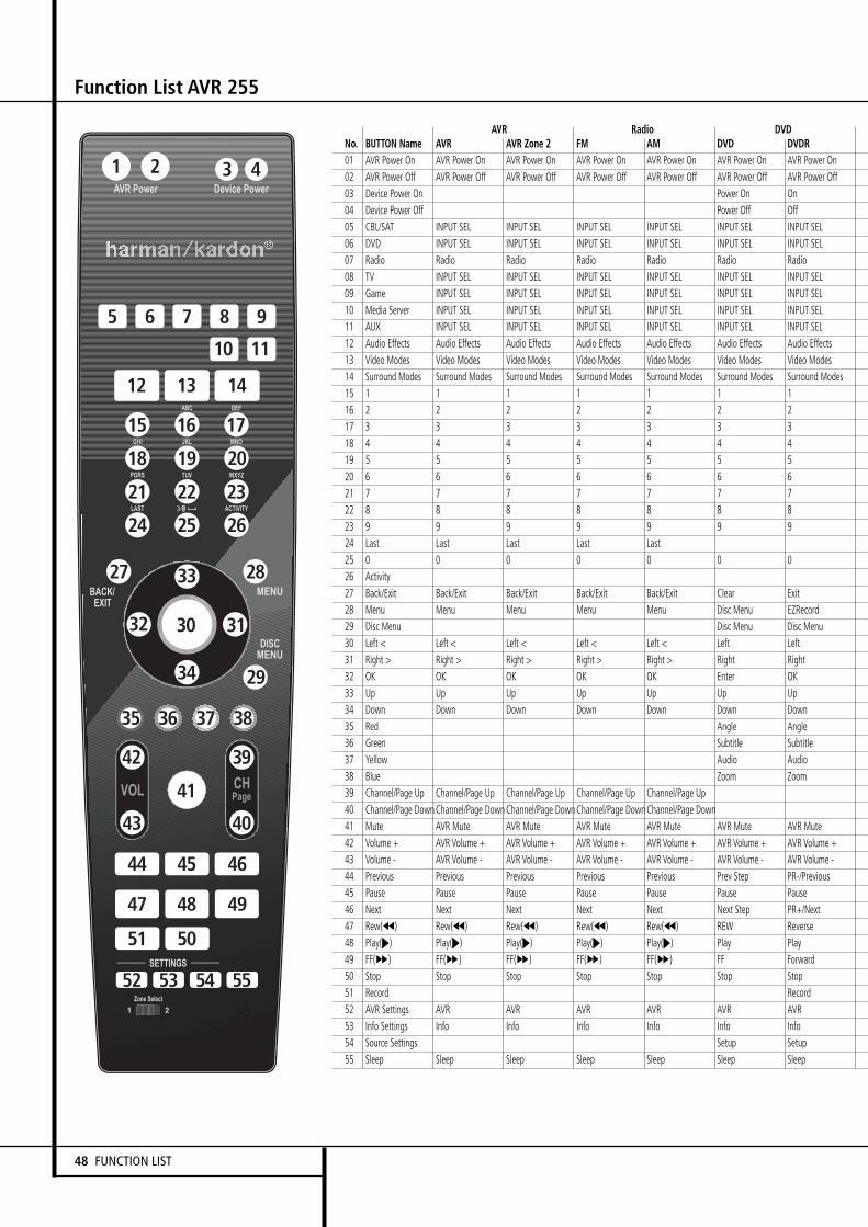
Function List AVR 255
4321
5
12
15 16 17
21 22 23
24
41
44 45 46
47 48 49
51
52 53 54 55
58
50
35 36 37 38
27
29
28
3130
33
32
34
42
43
39
40
25 26
18 19 20
13 14
6 7 8
10 11
9
48 FUNCTION LIST
No. BUTTON Name AVR AVR Zone 2 FM AM DVD DVDR01 AVR Power On AVR Power On AVR Power On AVR Power On AVR Power On AVR Power On AVR Power On02 AVR Power Off AVR Power Off AVR Power Off AVR Power Off AVR Power Off AVR Power Off AVR Power Off03 Device Power On Power On On04 Device Power Off Power Off Off05 CBL/SAT INPUT SEL INPUT SEL INPUT SEL INPUT SEL INPUT SEL INPUT SEL06 DVD INPUT SEL INPUT SEL INPUT SEL INPUT SEL INPUT SEL INPUT SEL07 Radio Radio Radio Radio Radio Radio Radio08 TV INPUT SEL INPUT SEL INPUT SEL INPUT SEL INPUT SEL INPUT SEL09 Game INPUT SEL INPUT SEL INPUT SEL INPUT SEL INPUT SEL INPUT SEL10 Media Server INPUT SEL INPUT SEL INPUT SEL INPUT SEL INPUT SEL INPUT SEL11 AUX INPUT SEL INPUT SEL INPUT SEL INPUT SEL INPUT SEL INPUT SEL12 Audio Effects Audio Effects Audio Effects Audio Effects Audio Effects Audio Effects Audio Effects13 Video Modes Video Modes Video Modes Video Modes Video Modes Video Modes Video Modes14 Surround Modes Surround Modes Surround Modes Surround Modes Surround Modes Surround Modes Surround Modes15 1 1 1 1 1 1 1 116 2 2 2 2 2 2 2 117 3 3 3 3 3 3 3 118 4 4 4 4 4 4 4 119 5 5 5 5 5 5 5 120 6 6 6 6 6 6 6 221 7 7 7 7 7 7 7 222 8 8 8 8 8 8 8 223 9 9 9 9 9 9 9 224 Last Last Last Last Last25 0 0 0 0 0 0 0 226 Activity27 Back/Exit Back/Exit Back/Exit Back/Exit Back/Exit Clear Exit28 Menu Menu Menu Menu Menu Disc Menu EZRecord29 Disc Menu Disc Menu Disc Menu30 Left < Left < Left < Left < Left < Left Left31 Right > Right > Right > Right > Right > Right Right32 OK OK OK OK OK Enter OK33 Up Up Up Up Up Up Up34 Down Down Down Down Down Down Down35 Red Angle Angle36 Green Subtitle Subtitle37 Yellow Audio Audio38 Blue Zoom Zoom39 Channel/Page Up Channel/Page Up Channel/Page Up Channel/Page Up Channel/Page Up40 Channel/Page DownChannel/Page DownChannel/Page DownChannel/Page DownChannel/Page Down41 Mute AVR Mute AVR Mute AVR Mute AVR Mute AVR Mute AVR Mute42 Volume + AVR Volume + AVR Volume + AVR Volume + AVR Volume + AVR Volume + AVR Volume +43 Volume - AVR Volume - AVR Volume - AVR Volume - AVR Volume - AVR Volume - AVR Volume -44 Previous Previous Previous Previous Previous Prev Step PR-/Previous45 Pause Pause Pause Pause Pause Pause Pause46 Next Next Next Next Next Next Step PR+/Next47 Rew(G) Rew(G) Rew(G) Rew(G) Rew(G) REW Reverse48 Play(N) Play(N) Play(N) Play(N) Play(N) Play Play49 FF(H) FF(H) FF(H) FF(H) FF(H) FF Forward50 Stop Stop Stop Stop Stop Stop Stop51 Record Record52 AVR Settings AVR AVR AVR AVR AVR AVR53 Info Settings Info Info Info Info Info Info54 Source Settings Setup Setup55 Sleep Sleep Sleep Sleep Sleep Sleep Sleep
AVR Radio DVD

Function List AVR 255
ENGLI
SH
FUNCTION LIST 49
No. DMC250 DMC1000 TV CBL/SAT UR Function CD HDTV PVD VCR01 AVR Power On AVR Power On AVR Power On AVR Power On AVR Power On AVR Power On AVR Power On AVR Power On AVR Power On02 AVR Power Off AVR Power Off AVR Power Off AVR Power Off AVR Power Off AVR Power Off AVR Power Off AVR Power Off AVR Power Off03 On On Power On Power On Play Power On Power On Power On Power On04 Off Off Power Off Power Off Stop Power Off Power Off Power Off Power Off05 INPUT SEL INPUT SEL INPUT SEL INPUT SEL INPUT SEL INPUT SEL INPUT SEL INPUT SEL INPUT SEL06 INPUT SEL INPUT SEL INPUT SEL INPUT SEL INPUT SEL INPUT SEL INPUT SEL INPUT SEL INPUT SEL07 Radio Radio Radio Radio Radio Radio Radio Radio Radio08 INPUT SEL INPUT SEL INPUT SEL INPUT SEL INPUT SEL INPUT SEL INPUT SEL INPUT SEL INPUT SEL09 INPUT SEL INPUT SEL INPUT SEL INPUT SEL INPUT SEL INPUT SEL INPUT SEL INPUT SEL INPUT SEL10 INPUT SEL INPUT SEL INPUT SEL INPUT SEL INPUT SEL INPUT SEL INPUT SEL INPUT SEL INPUT SEL11 INPUT SEL INPUT SEL INPUT SEL INPUT SEL INPUT SEL INPUT SEL INPUT SEL INPUT SEL INPUT SEL12 Audio Effects Audio Effects Audio Effects Audio Effects Audio Effects Audio Effects Audio Effects Audio Effects Audio Effects13 Video Modes Video Modes Video Modes Video Modes Video Modes Video Modes Video Modes Video Modes Video Modes14 Surround Modes Surround Modes Surround Modes Surround Modes Surround Modes Surround Modes Surround Modes Surround Modes Surround Modes15 1 1 1 1 1 1 1 1 116 2 2 2 2 2 2 2 2 217 3 3 3 3 3 3 3 3 318 4 4 4 4 4 4 4 4 419 5 5 5 5 5 5 5 5 520 6 6 6 6 6 6 6 6 621 7 7 7 7 7 7 7 7 722 8 8 8 8 8 8 8 8 823 9 9 9 9 9 9 9 9 924 Back Enter Prev.Ch Instant Replay25 0 0 0 0 0 0 0 0 02627 Return Back Exit Clear Exit/Cancel Exit Clear28 Source Menu Menu Menu Start Menu Menu Menu29 Disc Menu Disc Menu DVD Menu Osd Av30 Left < Left < Left < Left < Left Left Left Left31 Right > Right > Right > Right > Right Right Right Right32 Enter Enter OK OK Select Enter Set up OK33 Up Up Up Up Up Up Up Up34 Down Down Down Down Down Down Down Down35 Angle Angle Red 2 Open/Close Caption Mark36 Subtitle Subtitle Green Í Random Play Fav.Ch Repeat37 Audio Audio Yellow K Repeat Mts Jump Up38 Zoom Zoom Blue X Intro Scan Aspect Jump Down39 Channel Up Channel Up Scan Up (+10) Channel Up Channel Up CH+40 Channel Down Channel Down Scan Down Disk Skip Channel Down Channel Down CH-41 AVR Mute AVR Mute AVR Mute AVR Mute AVR Mute AVR Mute AVR Mute AVR Mute AVR Mute42 AVR Volume + AVR Volume + AVR Volume + AVR Volume + AVR Volume + AVR Volume + AVR Volume + AVR Volume + AVR Volume +43 AVR Volume - AVR Volume - AVR Volume - AVR Volume - AVR Volume - AVR Volume - AVR Volume - AVR Volume - AVR Volume -44 Previous Previous Text Cancel Slow Down Skip Down Back Last Clip Scan Down45 Pause Pause Text Off Pause Pause Pause Pause Pause46 Next/Step Next/Step Text Timed Slow Up Skip Up Replay Next Clip Scan Up47 Rew(G) Rew(G) Text Reveal Prev R. Search Rewind Rewind Rew48 Play(N) Play(N) Text On Play Play Play Play Play49 FF(H) FF(H) Text Index Next F. Search Fast Forward Fast Forward FF50 Stop Stop Stop Stop Stop Stop Stop51 Record Record Subtitle Time Record Record Rec52 AVR AVR AVR AVR AVR AVR AVR AVR AVR53 Info Info Info Info Info Info Info Info Info54 Setup Setup TV/VCR Program TV/VCR TV/DVR TV/VCR55 Sleep Sleep Sleep Sleep Sleep Sleep Sleep Sleep Sleep
Server TV CBL/SAT Game AUX
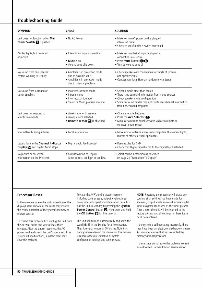
Troubleshooting Guide
Processor Reset
In the rare case where the unit’s operation or thedisplays seem abnormal, the cause may involvethe erratic operation of the system’s memory ormicroprocessor.
To correct this problem, first unplug the unit fromthe AC wall outlet and wait at least threeminutes. After the pause, reconnect the ACpower cord and check the unit’s operation. If thesystem still malfunctions, a system reset mayclear the problem.
To clear the AVR’s entire system memoryincluding tuner presets, output level settings,delay times and speaker configuration data, firstput the unit in Standby by pressing the SystemPower Control button2. Next press and holdthe OK button 6 for five seconds.
The unit will turn on automatically and show theword RESET in the Display for a few seconds.Then it reverts to normal ON status. Note thatonce you have cleared the memory in this manner,it is necessary to re-establish all systemconfiguration settings and tuner presets.
NOTE: Resetting the processor will erase anyconfiguration settings you have made forspeakers, output levels, surround modes, digitalinput assignments as well as the tuner presets.After a reset the unit will be returned to thefactory presets, and all settings for these itemsmust be reentered.
If the system is still operating incorrectly, theremay have been an electronic discharge or severeAC line interference that has corrupted thememory or microprocessor.
If these steps do not solve the problem, consultan authorized Harman Kardon service depot.
SYMPTOM CAUSE SOLUTION
Unit does not function when Main • No AC Power • Make certain AC power cord is pluggedPower Switch 1 is pushed into a live outlet
• Check to see if outlet is switch controlled
Display lights, but no sound • Intermittent input connections • Make certain that all input and speakeror picture connections are secure
• Mute is on • Press Mute button G• Volume control is down • Turn up volume control
No sound from any speaker; • Amplifier is in protection mode • Check speaker-wire connections for shorts at receiverProtect Warning in Display due to possible short and speaker ends
• Amplifier is in protection mode • Contact your local Harman Kardon service depotdue to internal problems
No sound from surround or • Incorrect surround mode • Select a mode other than Stereocenter speakers • Input is mono • There is no surround information from mono sources
• Incorrect configuration • Check speaker mode configuration• Stereo or Mono program material • Some surround modes may not create rear-channel information
from nonencoded programs
Unit does not respond to •Weak batteries in remote • Change remote batteriesremote commands •Wrong device selected • Press the AVR Selector 5
• Remote sensor Ó is obscured • Make certain front-panel sensor is visible to remote orconnect remote sensor
Intermittent buzzing in tuner • Local interference • Move unit or antenna away from computers, fluorescent lights,motors or other electrical appliances
Letters flash in the Channel Indicator • Digital audio feed paused • Resume play for DVDDisplay $ and Digital Audio stops • Check that Digital Signal is fed to the Digital Input selected
No picture or on-screen • AVR Resolution to Display • Select correct Resolution as describedinformation on the TV screen. is not correct, too high or too low. on page 21 "Resolution To Display"
50 TROUBLESHOOTING GUIDE

Technical Specifications
Audio SectionStereo ModeContinuous Average Power (FTC)
AVR 255: 65 Watts per channel, 20Hz - 20 kHzAVR 355: 70 Watts per channel, 20Hz - 20 kHz@ < 0.07% THD, both channels driven into 8 ohms
7 Channel Surround ModesPower Per Individual Channel, with all channels driven
Front L&R channels:AVR 255: 50 Watts per channelAVR 355: 65 Watts per channel@ < 0.07% THD, 20Hz–20kHz into 8 ohms
Center channel:AVR 255: 50 WattsAVR 355: 65 Watts@ < 0.07% THD, 20Hz–20kHz into 8 ohms
Surround (L & R Side, Back) channels:AVR 255: 50 Watts per channelAVR 355: 65 Watts per channel@ < 0.07% THD, 20Hz–20kHz into 8 ohms
Input Sensitivity/ImpedanceLinear (High Level) 200mV/47kohms
Signal-to-Noise Ratio (IHF-A) 100dB
Surround System Adjacent Channel SeparationAnalog Decoding 40dB(Pro Logic, etc.)Dolby Digital (AC-3) 55dBDTS 55dB
Frequency Response@ 1W (+0dB, –3dB) 10Hz–130kHz
High InstantaneousCurrent Capability (HCC) ±35 Amps
Transient IntermodulationDistortion (TIM) Unmeasurable
Rise Time 16 µsec
Slew Rate 40V/µsec**
FM Tuner SectionFrequency Range 87.5–108MHzUsable Sensitivity IHF 1.3 µV/13.2dBfSignal-to-Noise Ratio Mono/Stereo: 70/68dB (DIN)Distortion Mono/Stereo: 0.2/0.3%Stereo Separation 40dB @ 1kHzSelectivity ±400kHz: 70dBImage Rejection 80dBIF Rejection 90dB
AM Tuner SectionFrequency Range 522–1620kHzSignal-to-Noise Ratio 45dBUsable Sensitivity Loop: 500µVDistortion 1kHz, 50% Mod: 0.8%Selectivity ±10kHz: 30dB
Video SectionVideo Format PAL/NTSCInput Level/Impedance 1Vp-p/75 ohmsOutput Level/Impedance 1Vp-p/75 ohmsVideo Frequency Response(Composite and S-Video) 10Hz–8MHz (-3dB)Video FrequencyResponse (Component) 10Hz–100MHz (-3dB)
GeneralPower Requirement AC 220–240V/50HzPower Consumption AVR 255: Standby < 1W,
540W maximum
AVR 355: Standby < 3W,890W maximum
(7 channels driven)
Dimensions (Max)Width 440mmHeight 165mmDepth 382mmWeight net AVR 255: 14,0 kg
AVR 355: 14,4 kg
Depth measurement includes knobs, buttons and terminal connections.Height measurement includes feet and chassis.All features and specifications are subject to change without notice.
Harman Kardon, The Bridge and Logic 7 are registered trademarks ofHarman International Industries, Incorporated.
is a trademark of Harman International Industries, Inc.
*Manufactured under license from Dolby Laboratories."Dolby True HD", "Dolby Digital Plus", “Dolby,” “Pro Logic” and the Double-D symbol aretrademarks of Dolby Laboratories.
"DTS-HD Master Audio", "DTS-HD", "DTS","DTS ES","Neo:6"and"96/24" aretrademarks of DTS,Inc.
SA-CD is a trademark of Sony Electronics, Inc.
Blu-ray Disc is a trademark of the Blu-ray Disc Association.
Apple and iPod are registered trademarks of Apple Computer, Inc.
Cirrus is a registered trademark of Cirrus Logic Corp.
**Without input anti slewing and output isolation networks.
A-BUS and A-BUS/READY® Ready are registered trademarks of Leisure Tech Electronics Pty LtdAustralia.
Faroudja and DCDi by Faroudja are trademarks of Genesis Microchip, Inc.
HD-DVD is a trademark of the DVD Format/Logo Licensing Corporation (DVD FLLC).
HDMI, the HDMI logo and High-Definition Multimedia Interface are trademarks or registeredtrademarks of HDMI Licensing, LLC.
This product incorporates copyright protection technology that is protected by methodclaims of certain U.S. patents and other intellectual property rights owned by MacrovisionCorporation and other rights owners. Use of this copyright protection technology must beauthorized by Macrovision Corporation, and is intended for home and other limited viewinguses only unless otherwise authorized by Macrovision Corporation. Reverse engineering ordisassembly is prohibited.
ENGLI
SH
TECHNICAL SPECIFICATIONS 51

Appendix – Default settings, worksheets, remote product codes
Table A1 – Recommended Source Component Connections
Device Type AVR Source Digital Audio Connection Analog Audio Connection Video Connections
Cable TV, satellite TV, HDTV CBL/SAT HDMI 2 Analog 1 HDMI 2or other device that deliverstelevision programs
DVD Audio/Video, SACD, DVD HDMI 1 Analog 2 HDMI 1Blu-ray Disc, HD-DVD player
Media Server, including Media Server Optical 2 Analog 5 S-Video 1Harman Kardon DMC 1000
TV TV Optical 1 Analog 3 Component 1*Video game console Game HDMI 3 Analog 4 HDMI 3
Any audio or video device, AUX Coax Front Analog Front Composite Front (not used fore.g. CD player, camcorder, audio-only devices)cassette deck
Recorder Any Coaxial 1 or 2 input and Analog 4 inputs and outputs Composite OR S-Video 2 inputCoaxial Output and output
Portable audio player AUX Any Stereo Jack (use mini-plug Not required.cable, not included)
*Make this connection only when using the TV source for a non-display device. Do not connect your television’s or video display’s video output to the AVR at any time.
52 APPENDIX
APPENDIX – SETTINGS WORKSHEET
Table A2 – Source Setting Defaults
Cable/Sat DVD Media Server Radio TV Game AUX
Surround Modes (Auto Select) Logic 7 Movie Logic 7 Movie Logic 7 Movie Logic 7 Movie Logic 7 Movie Logic 7 Movie Logic 7 Movie
Video Input HDMI 2 HDMI 1 S-Video 1 N/A Component 1 HDMI 3 Composite Front
Audio Input HDMI 2 HDMI 1 Optical 2 N/A Optical 1 HDMI 3 Coaxial Front
Resolution to Display 576i 576i 576i 576i 576i 576i 576i
Audio Auto Polling Analog 1 Analog 2 Analog 5 N/A Analog 3 Analog 4 Analog Front
Zone 2 Audio Analog 1 Analog 2 Analog 5 N/A Analog 3 Analog 4 Analog Front
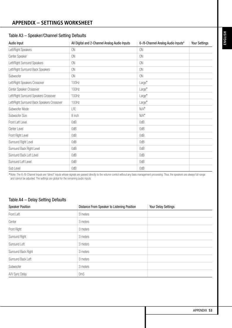
Table A3 – Speaker/Channel Setting Defaults
Audio Input All Digital and 2-Channel Analog Audio Inputs 6-/8-Channel Analog Audio Inputs* Your Settings
Left/Right Speakers ON ON
Center Speaker ON ON
Left/Right Surround Speakers ON ON
Left/Right Surround Back Speakers ON ON
Subwoofer ON ON
Left/Right Speakers Crossover 100Hz Large*Center Speaker Crossover 100Hz Large*Left/Right Surround Speakers Crossover 100Hz Large*Left/Right Surround Back Speakers Crossover 100Hz Large*Subwoofer Mode LFE N/A*Subwoofer Size 8 inch N/A*Front Left Level 0dB 0dB
Center Level 0dB 0dB
Front Right Level 0dB 0dB
Surround Right Level 0dB 0dB
Surround Back Right Level 0dB 0dB
Surround Back Left Level 0dB 0dB
Surround Left Level 0dB 0dB
Sub Level 0dB 0dB
*Note: The 6-/8-Channel Inputs are “direct” inputs whose signals are passed directly to the volume control without any bass management processing. Thus, the speakers are always full-rangeand cannot be adjusted. The settings are global for the remaining audio inputs.
APPENDIX 53
ENGLI
SH
APPENDIX – SETTINGS WORKSHEET
Table A4 – Delay Setting Defaults
Speaker Position Distance From Speaker to Listening Position Your Delay Settings
Front Left 3 meters
Center 3 meters
Front Right 3 meters
Surround Right 3 meters
Surround Left 3 meters
Surround Back Right 3 meters
Surround Back Left 3 meters
Subwoofer 3 meters
A/V Sync Delay 0mS

54 APPENDIX
APPENDIX – SETTINGS WORKSHEET
Table A6 – Audio Effects Settings
Default Cable/Sat DVD Media Server Radio TV Game AUX
Tone Control Off
Treble 0dB
Bass 0dB
LFE Trim Off
Night Mode Off
Table A7 – Video Modes Settings
Default Cable/Sat DVD Media Server Radio TV Game AUX
Video Mode Processor Off
Brightness* 50
Contrast* 50
Color* 50
Sharpness* 50
Picture Adjust Auto Fit
Noise Reduction** 0ff
MPEG Noise Reduction** 0ff
Cross Color Suppressor** Off
Film Mode Detect** Off
*Note: These settings are only available when the Video Mode is set to Custom.
**Note: These settings are only displayed when Advanced Video Settings is selected.
Table A5 – Source Settings
Cable/Sat DVD Media Server Radio TV Game AUX
Surround Modes
Video Input
Audio Input
Resolution to Display
Adjust Lip Sync
Change Name
Audio Auto Polling
Zone 2 Audio
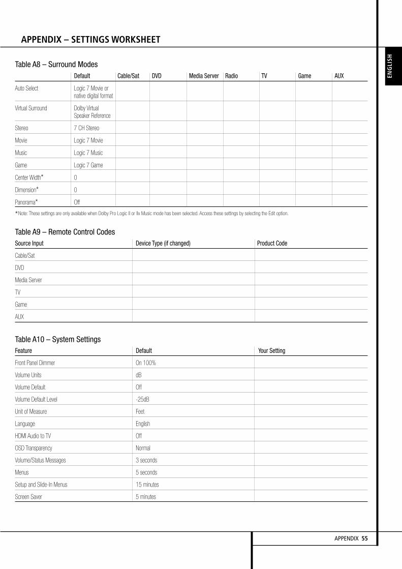
APPENDIX 55
ENGLI
SH
APPENDIX – SETTINGS WORKSHEET
Table A8 – Surround ModesDefault Cable/Sat DVD Media Server Radio TV Game AUX
Auto Select Logic 7 Movie ornative digital format
Virtual Surround Dolby VirtualSpeaker Reference
Stereo 7 CH Stereo
Movie Logic 7 Movie
Music Logic 7 Music
Game Logic 7 Game
Center Width* 0
Dimension* 0
Panorama* Off
*Note: These settings are only available when Dolby Pro Logic II or IIx Music mode has been selected. Access these settings by selecting the Edit option.
Table A9 – Remote Control CodesSource Input Device Type (if changed) Product Code
Cable/Sat
DVD
Media Server
TV
Game
AUX
Table A10 – System SettingsFeature Default Your Setting
Front Panel Dimmer On 100%
Volume Units dB
Volume Default Off
Volume Default Level -25dB
Unit of Measure Feet
Language English
HDMI Audio to TV Off
OSD Transparency Normal
Volume/Status Messages 3 seconds
Menus 5 seconds
Setup and Slide-In Menus 15 minutes
Screen Saver 5 minutes

56 APPENDIX
APPENDIX – SETTINGS WORKSHEET
Table A11 – Zone 2 Settings
Source Input Device Type (if changed) Your Settings
Status Off
Source Cable/Sat
Volume -25dB
Surround Back Amps Main Room
APPENDIX 57
ENGLI
SH
APPENDIX – SETTINGS WORKSHEET

250 Crossways Park Drive,Woodbury, New York 11797www.harmankardon.comHarman Consumer Group, Inc.:2, route de Tours, 72500 Château-du-Loir, France© 2008 Harman Kardon, IncorporatedPart No.: CQX1A1318Z