orrison ros. o. October 2020 VENTING GUIDE
40
A Guide Used to Assist in Equipment Selection for Aboveground Storage Tanks VENTING GUIDE This guide is intended for reference use only. All final details of design and construction shall meet the requirements of federal, state, and local codes. In cases where plan approval is required, such approval shall be obtained from the authority having jurisdiction before any work is performed. The equipment presented in the Guide applies only to shop fabricated tanks. for aboveground storage tanks October 2020
Transcript of orrison ros. o. October 2020 VENTING GUIDE

Morrison Bros. Co.
A Guide Used to Assist in Equipment Selection for Aboveground Storage Tanks
VENTINGGUIDE
This guide is intended for reference use only. All final details of design and construction shall meet the requirements of federal, state, and local codes. In cases where plan approval is required, such approval shall be obtained from the authority having jurisdiction before any work is performed. The equipment presented in the Guide applies only to shop fabricated tanks.
for aboveground storage tanks
October 2020

Page i

Morrison Bros. Co.
Contents PageI. Background Information ii References ii Definitions 1
II. Example Calculations for Vent Selection HorizontalCylindricalStorageTank 2 VerticalCylindricalStorageTank 3 HorizontalRectangularStorageTank 4
VentingExceptions:SpecialPurposeTanks 5VentCombinationExamples 6
III. Calculation TablesPre-calculatedHorizontalCylindricalTanks 7-8Pre-calculatedVerticalCylindricalStorageTanks 9Pre-calculatedHorizontalRectangularStorageTanks 10WettedAreasforHorizontalCylindricalTanks 11WettedAreasforVerticalCylindricalTanks 12EmergencyVentingCapacity 13GallonCapacityperFootofLength 14VentCapacity 15-16
IV. Vent SelectionMorrisonVentingEquipment 18-29
V. Aboveground Fuel Storage DiagramsPressureSystems 30-31SuctionSystems 32-33Generator 34BulkStorage 35
Page i

Venting Guide
References
NFPA 20 “StandardfortheInstallationofStationaryPumpsforFireProtection”2019Edition.National FireProtectionAssociation,1BatterymarchPark,Quincy,MA02269
NFPA 30 “FlammableandCombustibleLiquidsCode”2018Edition.NationalFireProtectionAssociation,1BatterymarchPark,Quincy,MA02269
UL 142 “SteelAbovegroundTanks”10thEdition.May17,2019.ULStandardsforSafety—ULPublicationStock,333PfingstenRoad,Northbrook,IL60062.Tel(847)272-8800
UL 142A “SpecialPurposeAbovegroundTanksforSpecificFlammableorCombustibleLiquids”1stEdition.May17,2019.ULStandardsforSafety–ULPublicationStock,333PfingstonRoad,Northbrook,IL60062.Tel(847)272-8800
ULC S601-07 StandardforShopFabricatedSteelAbovegroundTanksforFlammableandCombustibleLiquids.December2007.Underwriters’LaboratoriesofCanada7UnderwritersRd., Toronto,ONM1R3B4.Tel(514)757-3611
PEI RP200 “RecommendedPracticesforInstallationofAbovegroundStorageSystemsfor MotorVehicleFueling."PetroleumEquipmentInstitute,2008Edition.P.O.Box2380.Tulsa,OK,74101;Tel(918)494-9696
OSHA 1910.106 OccupationalSafetyandHealthStandards.March1,2016.OccupationalSafetyandHealthAdministration,200ConstitutionAve.,NW,Washington,DC20210.Tel(800)321-6742
API 2000 VentingAtmosphericandLow-PressureStorageTanks.1998.API,1220LStreet,NW,Washington,DC20005-4070.Tel(202)682-8000
Morrison Bros. Co. 570East7thStreet,Dubuque,Iowa52001.Tel(563)583-5701
Background Information
TheMorrisonBros.Co.VentingGuidewascreatedtoassistintheselectionofventingequipmentforabovegroundstoragetanks.Examplesonthenexttwopagesillustrateaventselectionprocess.Itisbesttoworkthroughtheexamplesbeforeattemptingtouseanyofthetablesinthisbook.
Tablesincludeexamplesforstandardsizedtanks.TheventingcapacitychartsandwettedareatablesweretakendirectlyfromNFPA30andUL142.
TheventselectionchapterincludesventingcapacitiesofspecificMorrisonvents.Thisdatawasobtainedfromresultsoflaboratorytestingandengineeringcalculations.CatalogpagesoftheMorrisonequipmentfollowtheventcapacitychart.
Page ii

Morrison Bros. Co.
Page 1
Definitions
Emergency Venting —Ventingsufficienttorelieveexcessiveinternalpressureinstoragetankscausedbyexposurefires.Ventingratemayexceedrequirementsofnormalatmosphericandproducttransfereffects.Insuchcases,theconstructionofthetankwilldetermineifadditionalventingcapacitymustbeprovided.
Atmospheric Tank —Astoragetankthathasbeendesignedtooperateatpressuresfromatmosphericthroughagaugepressureof1.0psi(6.9kPa)(i.e.,760mmHgthrough812mmHg)measuredatthetopofthetank.
Normal Vent —Anopening,constructionmethod,ordevicethatallowsthereliefofexcessiveinternalpressureorvacuumduringnormalstorageandoperations.
Pressure Relieving Devices —DefinedinNFPA30section22.7.3.1,whereentiredependenceforemergencyreliefisplaceduponpressurerelievingdevices,thetotalventingcapacityofbothnormalandemergencyventsshallbeenoughtopreventruptureoftheshellorbottomofthetankifvertical,oroftheshellorheadsifhorizontal.
Wetted Area —Exposedsurfaceorshellareaofatankusedindeterminingtheventingrequirementsneededforthatsizetankineventofanexposurefire.Inahorizontaltank,thewettedareaiscalculatedas75%oftheexposedsurfacearea.Inaverticaltank,thewettedareaiscalculatedasthefirst30ft.abovegradeoftheexposedshellareaofthetank.Inarectangulartank,thewettedareaiscalculatedasthetotalsurfaceareaofthetankbottomandthefoursides,excludingthetanktop.
SCFH — AbbreviationforStandardCubicFeetperHourusedtoquantifyormeasuretheairflowanddegreeofpressurereliefforventing calculations.
Vent Capacity —Themaximumrateofairflow(SCFH)recordedundertestconditionsatamaximumpressureof2.5PSIforspecificsizedemergencyvents.Thiscapacityratingisoftenrequiredtobeindicatedontheventitself.

Page 2
Venting Guide
STEP 5 Vent Selection
Optionsbasedonsizeofpiping,typeofproduct,flowrequirements,requiredventingcapacityandmounting.Forthesakeofthisexample,use2”piping,Class1Bliquid.Thenormalventsizeshouldbenosmallerthanthesystem piping,soaMorrison2”Fig.748A(20,000SCFH)isselected.
Totalrequiredventingcapacityforthistankexamplewasdeterminedtobe360,840SCFH.Normalventingand emergencyventingmaybecombinedtoreachthistotal.MorrisonVentCapacitiesarelistedonTableH,page15.Sincethe6”EmergencyVent(299,684SCFH)cannotprovideenoughadditionalcapacitytomeettherequirement,an8”EmergencyVent(503,517SCFH)isselected.Inspecifyingpressuresettings,itisrecommendedthattheEmergencyVentNOTbelessthanthenormalvent.Therefore,theventspecificationforthisexampleisasfollows:
NormalVent-2”Fig748A 20,000 SCFH (8ozpressure-1ozvacuum)
EmergencyVent-8”Fig244O 503,517 SCFH (16ozpressure)
TotalVentingProvided 523,517 SCFH
STEP 6 Verification
RefertoTableIonpage16showingventcombinationsandverifythetotalSCFHfigure.Alsorefertotheproductillustrationsonpages17-26andverifytheselectionforcorrectoptiononmaterialcompatibilityandmountingrequirements.
STEP 1 Pre-calculated Data for Common Sizes
FindtanksizeonTableAwhichcanbefoundonpage6.TablelistswettedareaandSCFHforcommonsizedhorizontaltanks.Fora10’x17’tank–wettedarea=518sq.ft.andrequiredventcapacity=360,840SCFH.ProceedtoStep5.
STEP 2 Wetted Area Table
IftanksizeisNOTlistedonTableA,page6,wettedareacanalsobefoundonTableD,page11.Followgridforthisexample–10’diameterx17’length=518sq.ft.ProceedtoStep4.
STEP 3 Calculate Wetted Area
IfthetanksizeisNOToneitherchart,wettedareacanbecalculated.ForHorizontalTanks,wettedarea=75%ofthetotalexposedsurfacearea.
For a 10’ x 17’ tank— 0.75[2(areaofeachend)+(areaofshell)]=wettedarea
π=3.1416,d=diameter,L=length,WA=wettedarea
WA=0.75[(πd2÷2)+(πdL)] 0.75[((3.1416)(102)÷2)+(3.1416)(10)(17)]
WA=518sq.ft.
STEP 4 Determine SCFH Requirement
UseTableF:VentingCapacityChartonpage13.Wettedareamustbeknown(518sq.ft.).Since518isbetween500and600onthechart,interpolationisneededandisdoneasfollows:
600sq.ft. 392,000 SCFH 500sq.ft. 354,000 SCFH Difference= 100sq.ft. 38,000 SCFH
38,000 = x 100 (518-500) x=6,840SCFH
TotalSCFHRequired:(6,840+354,000)=360,840SCFH
Vent Selection/Capacity Example 1
HORIZONTAL CYLINDRICAL STORAGE TANK
Tank Capacity 10,000 gallons
Tank Size 10 ft. dia x 17 ft. long

Page 2 Page 3
Morrison Bros. Co.
STEP 1 Pre-calculated Data for Common Sizes
FindtanksizeonTableBwhichcanbefoundonpage8-9.TablelistswettedareaandSCFHforcommonsizedverticaltanks.Fora10’x17’tank–wettedarea=613sq.ft.andrequiredventcapacity=396,680SCFH.ProceedtoStep5.
STEP 2 Wetted Area Table
IftanksizeisNOTlistedonTableB,page8-9,wettedareacanalsobefoundonTableE,page12.Followgridforthisexample–10’diameterx17’height=613sq.ft.ProceedtoStep4.
STEP 3 Calculate Wetted Area
IfthetanksizeisNOToneitherchart,wettedareacanbecalculated.ForVerticalTanks,wettedarea=exposedshellareaexcludingthetopsurfacetoelevationnotmorethan30ft.abovethebottom.
Fora10’x17’tank: WettedArea=(areaofshell)+(areaofbottomsurface)
π=3.1416,d=diameter,L=length,WA=wettedarea
WA=(πd)L+π(½d)² (3.1416)(10)(17)+(3.1416)(5²)
WA=613sq.ft.
STEP 4 Determine SCFH Requirement
UseTableF:VentingCapacityChartonpage13.Wettedareamustbeknown(613sq.ft.).Since613isbetween600and700onthechart,interpolationisneededandisdoneasfollows:
700sq.ft. 428,000 SCFH 600sq.ft. 392,000 SCFH Difference= 100sq.ft. 36,000 SCFH
36,000 = x 100 (613-600) x=4,680SCFH
TotalSCFHRequired:(4,380+392,000)=396,680SCFH
STEP 5 Vent Selection
Optionsbasedonsizeofpiping,typeofproduct,flowrequirements,requiredventingcapacityandmounting.Forthesakeofthisexample,use2”piping,Class1Bliquid.Thenormalventsizeshouldbenosmallerthanthesystem piping,soaMorrison2”Fig.748A(20,000SCFH)isselected.
Totalrequiredventingcapacityforthistankexamplewasdeterminedtobe396,680SCFH.Normalventingand emergencyventingmaybecombinedtoreachthistotal.MorrisonVentCapacitiesarelistedonTableH,page15.Sincethe6”EmergencyVent(299,684SCFH)cannotprovideenoughadditionalcapacitytomeettherequirement,an8”EmergencyVent(503,517SCFH)isselected.Inspecifyingpressuresettings,itisrecommendedthattheEmergencyVentNOTbelessthanthenormalvent.Therefore,theventspecificationforthisexampleisasfollows:
NormalVent-2”Fig748A 20,000 SCFH (8ozpressure-1ozvacuum)
EmergencyVent-8”Fig244O 503,517 SCFH (16ozpressure)
TotalVentingProvided 523,517 SCFH
STEP 6 Verification
RefertoTableIonpage16showingventcombinationsandverifythetotalSCFHfigure.Alsorefertotheproductillustrationsonpages17-26andverifytheselectionforcorrectoptiononmaterialcompatibilityandmountingrequirements.
Vent Selection/Capacity Example 2
VERTICAL CYLINDRICAL STORAGE TANK
Tank Capacity 10,000 gallons
Tank Size 10 ft. dia x 17 ft. high

Page 4
Venting Guide
Vent Selection/Capacity Example 3
STEP 1 Pre-calculated Data for Common Sizes
FindtanksizeonTableCwhichcanbefoundonpage10.TablelistswettedareaandSCFHforcommonsizedtanks.Fora274”Lx130”Wx65”H(22’10”Lx10’-10”Wx5’5”H)tank–wettedarea=612sq.ft.andrequiredvent capacity=396,320SCFH.ProceedtoStep4.
STEP 2 Wetted Area Table
IftanksizeisNOTlistedonTableC,page10,wettedareacanbecalculated.ForHorizontalRectangularTanks,wettedarea=exposedshellareaexcludingthetopsurfaceofthetank.
Fora274”Lx130”Wx65”Htank:
Wettedarea=(LxW)+2(LxH)+2(WxH) 144
L=length,W=width,H=height
(274x130)+2(274x65)+2(130x65) 144
WettedArea=612Sq.ft.
STEP 3 Determine SCFH Requirement
UseTableF:VentingCapacityChartonpage13.Wettedareamustbeknown(612sq.ft.).Since612isbetween600and700onthechart,interpolationisneededandisdoneasfollows:
700sq.ft. 428,000 SCFH 600sq.ft. 392,000 SCFH Difference= 100sq.ft. 36,000 SCFH
36,000 = x 100 (612-600) x=4,320SCFH
TotalSCFHRequired:(4,320+392,000)=396,320SCFH
STEP 4 Vent Selection
Optionsbasedonsizeofpiping,typeofproduct,flowrequirements,requiredventingcapacityandmounting.Forthesakeofthisexample,use2”piping,Class1Bliquid.Thenormalventsizeshouldbenosmallerthanthesystem piping,soaMorrison2”Fig.748A(20,000SCFH)isselected.
Totalrequiredventingcapacityforthistankexamplewasdeterminedtobe396,320SCFH.Normalventingand emergencyventingmaybecombinedtoreachthistotal.MorrisonVentCapacitiesarelistedonTableH,page15.Sincethe6”EmergencyVent(299,684SCFH)cannotprovideenoughadditionalcapacitytomeettherequirement,an8”EmergencyVent(503,517SCFH)isselected.Inspecifyingpressuresettings,itisrecommendedthattheEmergencyVentNOTbelessthanthenormalvent.Therefore,theventspecificationforthisexampleisasfollows:
NormalVent-2”Fig748A 20,000 SCFH (8ozpressure-1ozvacuum)
EmergencyVent-8”Fig244O 503,517 SCFH (16ozpressure)
TotalVentingProvided 523,517 SCFH
STEP 5 Verification
RefertoTableIonpage16showingventcombinationsandverifythetotalSCFHfigure.Alsorefertotheproduct illustrationsonpages17-26andverifytheselectionfor correctoptiononmaterialcompatibilityandmounting requirements.
Tank Capacity 10,000gallons
Tank Size 274”Lx130”Wx65”H
(22’-10”Lx10’-10”Wx5’5”H)
HORIZONTAL RECTANGULAR STORAGE TANK

Page 4 Page 5
Morrison Bros. Co.
Venting Exceptions: Special Purpose Tanks
ThefollowingtanksclassifiedinUL142A:• WorkTopTanks—forClassIIIFuelsandOils.• LubeOilTanks—forClassIIIBOils.• UsedOilTanks—forClassIIIBOils.
TheemergencyventopeningnominalsizeandtheventingcapacitymaybelowerthanrequiredbyUL142,Section8,Table8.1.Thesetypesoftanksmayqualifyforareductioninventingrequirementsperthefollowingchart:
Tank Size Percent emergency venting reductionTanks≤330gallons upto20percentTanks≤660gallons upto15percentTanks≤1250gallons upto10percentTanks≤5000gallons upto5percent
Source: ANSI/UL 142A Section 5, First Edition, May 17, 2019.

Page 6
Venting Guide
Table A: Vent Combination Examples
Note: All calculations are less screens.
Model 244 Emergency Vents used for venting capacities.
MORRISON VENTS SCFH2” Fig.748A-4ozP 20,0004” Fig.245-8ozP 129,369
TOTAL SCFH: 149,369
2” Fig.748A-8ozP 20,0006” Fig.245-8ozP 331,750
TOTAL SCFH: 351,750
2” Fig.748A-8ozP 20,0008” Fig.245-8ozP 527,441
TOTAL SCFH: 547,441
2” Fig.748A-8ozP 20,00010” Fig.245F-8ozP 972,110
TOTAL SCFH: 992,100
2” Fig.948A-2.5-6”wcP 36,72010” Fig.245F-8ozP 972,110 TOTAL SCFH: 1,008,830
3” Fig.748A-8ozP 43,00010” Fig.245F-8ozP 972,110 TOTAL SCFH: 1,015,110
2” Fig.749-8ozP 8,5004” Fig.245-8ozP 129,369
TOTAL SCFH: 137,869
3” Fig.748A-8ozP 43,0006” Fig.245-8ozP 331,750
TOTAL SCFH: 374,750
3” Fig.748A-8ozP 43,0008” Fig.245-8ozP 527,441
TOTAL SCFH: 570,441
3” Fig.922-8ozP 30,30010” Fig.245F-8ozP 972,110 TOTAL SCFH: 1,002,410
3” Fig.748A-8ozP 43,00010” Fig.245F-8ozP 972,110 TOTAL SCFH: 1,015,110
4” Fig.354 116,90010” Fig.245F-8ozP 972,110 TOTAL SCFH: 1,089,010
Model 245 Lightweight Emergency Vents used for venting capacities.
MORRISON VENTS SCFH2” Fig.748A-4ozP 20,0004” Fig.244O-8ozP 131,700
TOTAL SCFH: 151,700
2” Fig.748A-8ozP 20,0006” Fig.244O-16ozP 299,684
TOTAL SCFH: 319,684
2” Fig.748A-8ozP 20,0008” Fig.244O-16ozP 503,517
TOTAL SCFH: 523,517
2” Fig.748A-8ozP 20,00010” Fig.244OF-16ozP 890,275
TOTAL SCFH: 910,275
2” Fig.948A-2.5-6”wcP 36,72010” Fig.244OF-8ozP 890,275
TOTAL SCFH: 926,995
3” Fig.748A-8ozP 43,00010” Fig.244OF-10ozP 890,275
TOTAL SCFH: 933,275
2” Fig.749-8ozP 8,5004” Fig.244O-16ozP 131,700
TOTAL SCFH: 140,200
3” Fig.748A-8ozP 43,0006” Fig.244O-16ozP 299,684
TOTAL SCFH: 342,684
3” Fig.748A-8ozP 43,0008” Fig.244O-16ozP 503,517
TOTAL SCFH: 546,517
3” Fig.922-8ozP 30,30010” Fig.244OF-16ozP 890,275
TOTAL SCFH: 920,575
3” Fig.748A-8ozP 43,00010” Fig.244OF-8ozP 890,275
TOTAL SCFH: 933,275
4” Fig.354 116,90010” Fig.244OF-8ozP 890,275 TOTAL SCFH: 1,007,175

Page 6 Page 7
Morrison Bros. Co.
TANK
WETTEDAREA(Sq Ft)
REQ’D VENTCAPACITY
(SCFH)
EMERGENCYVENT SIZE
WITHOUT SCREEN (Inches)
EMERGENCYVENT SIZE
WITH SCREEN (Inches)
CAPACITY (Gallons)
DIAMETER(Ft or In)
LENGTH(Ft-In)
280 36” 5’-2” 47 49,520 3 3
300 38” 5’-0” 49 51,640 3 4
500 48” 5’-5” 69 72,650 4 4
530 46” 6’-0” 71 74,750 4 4
550 48" 6’-0” 75 78,950 4 4
1,000 48” 10’-8” 119 124,950 4 5
1,000 64” 6’-0” 109 114,450 4 4
1,500 64” 9’-0” 147 154,350 5 5
2,000 64” 12’-0” 184 193,200 6 6
2,500 64” 15’-0” 222 223,320 6 6
3,000 64” 18’-0” 259 243,680 6 6
3,000 6’-0” 14’-0” 240 233,400 6 6
4,000 64” 24’-0” 335 281,100 6 N/A
4,000 6’-0” 19’-0” 311 270,060 6 N/A
5,000 8’-0” 13’-4” 326 276,960 6 N/A
6,000 8’-0” 16’-0” 376 300,480 8 N/A
8,000 8’-0” 21’-4” 477 344,340 8 N/A
10,000 8’-0” 27’-0” 584 385,920 8 N/A
10,000 9’-0” 21’-0” 540 369,200 8 N/A
10,000 10’-0” 17’-0” 518 360,840 8 N/A
10,000 10’-6” 15’-7” 515 359,700 8 N/A
12,000 8’-0” 32’-0” 678 420,080 8 N/A
12,000 9’-0” 25’-0” 625 401,000 8 N/A
12,000 10’-0” 20’-6” 600 392,000 8 N/A
12,000 11’-0” 17’-0” 583 385,540 8 N/A
15,000 8’-0” 40’-0” 829 470,990 8 N/A
15,000 10’-6” 23’-5” 703 429,020 8 N/A
20,000 10’-0” 34’-2” 922 499,820 8 N/A
20,000 10’-6” 31’-0” 896 491,760 8 N/A
20,000 11’-0” 28’-0” 868 483,080 8 N/A
25,000 10’-6” 38’-6” 1,082 537,530 10 N/A
Table B: Pre-Calculated Data
HORIZONTAL CYLINDRICAL TANKS
(TABLE CONTINUED ON PAGE 8)

Page 8
Venting Guide
TANK
WETTEDAREA(Sq Ft)
REQ’D VENTCAPACITY
(SCFH)
EMERGENCYVENT SIZEWITHOUT
SCREEN (Inches)
EMERGENCYVENT SIZE
WITH SCREEN (Inches)
CAPACITY(Gallons)
DIAMETER(Ft or In)
LENGTH(Ft-In)
30,000 10'-0" 51'-2" 1,324 575,600 10 N/A
30,000 10’-6” 46’-3” 1,274 568,100 10 N/A
40,000 12'-0" 47'-6" 1,512 602,120 10 N/A
50,000 12'-0" 59'-6" 1,852 664,980 10 N/A
50,000 12'-6" 54'-6" 1,789 637,735 10 N/A
60,000 12'-0" 71'-0" 2,177 680,585 10 N/A
60,000 12'6" 65'5" 2,110 637,550 10 N/A
60,000 13'-0" 60'-6" 2,052 667,460 10 N/A
70,000 13'-0" 72'-0" 2,404 704,380 10 N/A
Table B: Pre-Calculated Data (continued from page 7)
HORIZONTAL CYLINDRICAL TANKS

Page 8 Page 9
Morrison Bros. Co.
Table C: Pre-Calculated Data
VERTICAL CYLINDRICAL TANKS
TANK
WETTEDAREA (SqFt)
REQ'D VENTCAPACITY(SCFH)
EMERGENCYVENT SIZEWITHOUT SCREEN(Inches)
EMERGENCYVENT SIZE
WITH SCREEN(Inches)
TANK CAPACITY(Gallons)
DIAMATER(FtorIn)
LENGTH(Ft-In)
280 36" 5'-2" 56 58,751 3" 4"300 38" 5'-0" 58 60,706 3" 4"500 48" 5'-5" 81 84,872 4" 4"530 46" 6'-0" 84 88,225 4" 4"550 48" 6'-0" 88 92,642 4" 4"1,000 48" 10'-8" 147 153,938 5" 5"1,000 64" 6'-0" 123 129,015 4" 5"1,500 64" 9'-0" 173 182,450 5" 6"2,000 64" 12'-0" 223 224,105 6" 6"2,500 64" 15'-0" 274 251,307 6" N/A3,000 6'-0" 14'-0" 292 260,927 6" N/A3,000 64" 18'-0" 324 276,009 6" N/A4,000 64" 24'-0" 424 322,275 8" N/A4,000 6'-0" 19'-0" 386 305,479 8" N/A5,000 8'-0" 13'-4" 385 304,977 8" N/A6,000 8'-0" 16'-0" 452 334,003 8" N/A8,000 8'-0" 21'-4" 586 386,843 8" N/A10,000 8'-0" 27'-0" 729 437,809 8" N/A10,000 9'-0" 21'-0" 657 412,656 8" N/A10,000 10'-0" 17'-0" 613 396,540 8" N/A10,000 10'-6" 15'-7" 601 392,228 8" N/A12,000 8'-0" 32'-0" 804 463,317 8" N/A12,000 9'-0" 25'-0" 770 451,961 8" N/A12,000 10'-0" 20'-6" 723 435,672 8" N/A12,000 11'-0" 17'-0" 683 421,704 8" N/A15,000 8'-0" 40'-0" 804 463,317 8" N/A15,000 10'-6" 23'-5" 859 480,299 8" N/A20,000 10'-0" 34'-2" 1,021 527,468 10" N/A20,000 10'-6" 31'-0" 1,076 536,572 10" N/A20,000 11'-0" 28'-0" 1,063 534,336 10" N/A25,000 10'-6" 38'-6" 1,076 536,572 10" N/A30,000 10'-6" 46'-3" 1,076 536,572 10" N/A30,000 12'-0" 35'-6" 1,244 563,610 10" N/A30,000 12'-6" 32'-9" 1,301 572,122 10" N/A40,000 12'-0" 47'-6" 1,244 563,610 10" N/A40,000 12'-6" 43'-8" 1,301 572,122 10" N/A40,000 13'-0" 40'-4" 1,358 580,693 10" N/A49,500 13'-0" 50'-0" 1,358 580,693 10" N/A57,000 14'-0" 50'-0" 1,473 596,910 10" N/A

Page 10
Venting Guide
Table D: Pre-Calculated Data
HORIZONTAL RECTANGULAR TANKS
TANK
WETTED AREA (Sq Ft)
REQ’D VENT CAPACITY
(SCFH)
EMERGENCY VENT SIZE WITHOUT
SCREEN (Inches)
EMERGENCY VENT SIZE
WITH SCREEN (Inches)
CAPACITY(Gallons)
LENGTH(Ft-In)
WIDTH(Ft-In)
HEIGHT(Ft-In)
125 6’-8” 2’-9” 1’-0” 37 38,950 3 3
186 2’-8” 2’-8” 3’-6” 44 46,340 3 3
250 4’-4” 4’-0” 1’-11” 49 51,640 3 4
250 6’-8” 2’-9” 1’-11” 54 56,900 3 4
500 7’-6” 3’-0” 3’-0” 86 90,560 4 4
500 10’-0” 3’-6” 2’-0” 89 93,740 4 4
1,000 9’-8” 4’-8” 3’-0” 131 137,550 5 5
1,000 10’-0” 4’-7” 2'-11" 133 139,650 5 5
2,000 10’-2” 6’-11” 3’-10” 201 211,560 6 6
2,000 10’-8” 6’-4” 4’-0” 204 213,240 6 6
2,500 10’-2” 6’-11” 4’-9” 233 229,480 6 6
3,000 8’-6” 6’-10” 7’-2” 278 253,560 6 N/A
3,000 13’-9” 5’-5” 5’-5” 282 255,640 6 N/A
4,000 11’-4” 6’-10” 7’-2” 338 282,480 6 N/A
4,000 18’-2” 5’-5” 5’-5” 354 289,920 6 N/A
5,000 22’-9” 5’-5” 5’-5” 428 323,760 8 N/A
6,000 13’-8” 10’-10” 5’-5” 413 317,460 8 N/A
6,000 16’-5” 6’-10” 7’-2” 445 330,900 8 N/A
6,000 27’-4” 5’-5” 5’-5” 503 355,140 8 N/A
8,000 18’-2” 10’-10” 5’-5” 511 358,180 8 N/A
8,000 21’-11” 6’-10” 7’-2” 562 377,560 8 N/A
10,000 22’-10” 10’-10” 5’-5” 612 396,320 8 N/A
10,000 27’-5” 6’-10” 7’-2” 678 420,080 8 N/A
12,000 27’-4” 10’-10” 5’-5” 710 431,400 8 N/A
12,000 32’-11” 6’-10” 7’-2” 795 460,300 8 N/A

Page 10 Page 11
Morrison Bros. Co.
SI Units: 1 Ft = 0.30 m; 1 sq ft = 0.09 sq mSource for Chart: UL 142, Table A-2, 10th Edition, May 17, 2019.
Table E: Approximate Wetted Areas
HORIZONTAL CYLINDRICAL TANKS
Tank Diameter
3 Ft 4 Ft 5 Ft 6 Ft 7 Ft 8 Ft 9 Ft 10 Ft 11 Ft 12 Ft 13 Ft
Tank Length
Approximate Wetter Area of Tanks With Flat Heads, Square Feet
3 Ft 32
4 Ft 39 55
5 Ft 46 65 88
6 Ft 53 74 100 128
7 Ft 60 84 112 142 173
8 Ft 67 93 124 156 190 226
9 Ft 74 102 136 170 206 245 286
10 Ft 81 112 147 184 223 264 308 353
11 Ft 88 121 159 198 239 283 329 377 428
12 Ft 95 131 171 213 256 301 350 400 454 509
13 Ft 102 140 183 227 272 320 371 424 480 537 598
14 Ft 109 150 194 241 289 339 393 447 506 565 628
15 Ft 116 159 206 255 305 358 414 471 532 594 659
16 Ft 123 169 218 269 322 377 435 495 558 622 690
17 Ft 130 178 230 283 338 395 456 518 584 650 720
18 Ft 137 188 242 298 355 414 477 542 610 678 751
19 Ft 197 253 312 371 433 499 565 636 707 781
20 Ft 206 265 326 388 452 520 589 662 735 812
21 Ft 216 277 340 404 471 541 612 688 763 843
22 Ft 225 289 354 421 490 562 636 714 792 873
23 Ft 235 300 368 437 508 584 659 740 820 904
24 Ft 244 312 383 454 527 605 683 765 848 935
25 Ft 324 397 470 546 626 706 791 876 965
26 Ft 336 411 487 565 647 730 817 905 996
27 Ft 347 425 503 584 668 754 843 933 1027
28 Ft 359 440 520 603 690 777 869 961 1057
29 Ft 371 454 536 621 711 801 895 989 1088
30 Ft 383 468 553 640 732 824 921 1018 1118
31 Ft 395 482 569 659 753 848 947 1046 1149
32 Ft 496 586 678 775 871 973 1074 1180
33 Ft 510 602 697 796 895 999 1103 1210
34 Ft 524 619 715 817 918 1025 1131 1241
35 Ft 539 635 734 838 942 1051 1159 1272
36 Ft 553 652 753 860 966 1077 1187 1302
37 Ft 567 668 772 881 989 1103 1216 1333
Tank Diameter
3 Ft 4 Ft 5 Ft 6 Ft 7 Ft 8 Ft 9 Ft 10 Ft 11 Ft 12 Ft 13 Ft
Tank Length
Approximate Wetter Area of Tanks With Flat Heads, Square Feet
38 Ft 685 791 902 1013 1129 1244 1363
39 Ft 701 810 923 1036 1155 1272 1394
40 Ft 718 828 944 1060 1181 1301 1425
41 Ft 734 847 966 1083 1207 1329 1455
42 Ft 751 866 987 1107 1233 1357 1486
43 Ft 767 885 1008 1130 1259 1385 1517
44 Ft 904 1029 1154 1284 1414 1547
45 Ft 923 1051 1178 1310 1442 1578
46 Ft 941 1072 1201 1336 1470 1609
47 Ft 960 1093 1225 1362 1498 1639
48 Ft 979 1114 1248 1388 1527 1670
49 Ft 1135 1272 1414 1555 1700
50 Ft 1157 1295 1440 1583 1731
51 Ft 1178 1319 1466 1612 1762
52 Ft 1199 1342 1492 1640 1792
53 Ft 1220 1366 1518 1668 1823
54 Ft 1246 1389 1544 1697 1854
55 Ft 1263 1413 1570 1725 1884
56 Ft 1437 1593 1753 1915
57 Ft 1460 1622 1781 1945
58 Ft 1484 1648 1809 1976
59 Ft 1507 1674 1839 2007
60 Ft 1531 1700 1867 2037
61 Ft 1726 1895 2068
62 Ft 1752 1923 2099
63 Ft 1778 1951 2129
64 Ft 1803 1980 2160
65 Ft 1829 2007 2190
66 Ft 1855 2036 2221
67 Ft 2064 2252
68 Ft 2093 2282
69 Ft 2121 2313
70 Ft 2149 2343
71 Ft 2177 2374
72 Ft 2205 2405
Page 12
Venting Guide
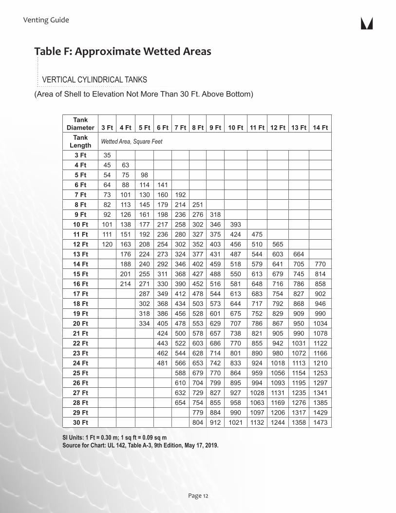
(AreaofShelltoElevationNotMoreThan30Ft.AboveBottom)
SI Units: 1 Ft = 0.30 m; 1 sq ft = 0.09 sq mSource for Chart: UL 142, Table A-3, 9th Edition, May 17, 2019.
Table F: Approximate Wetted Areas
VERTICAL CYLINDRICAL TANKS
Tank Diameter 3 Ft 4 Ft 5 Ft 6 Ft 7 Ft 8 Ft 9 Ft 10 Ft 11 Ft 12 Ft 13 Ft 14 Ft
Tank Length Wetted Area, Square Feet
3 Ft 354 Ft 45 635 Ft 54 75 986 Ft 64 88 114 1417 Ft 73 101 130 160 1928 Ft 82 113 145 179 214 2519 Ft 92 126 161 198 236 276 318
10 Ft 101 138 177 217 258 302 346 39311 Ft 111 151 192 236 280 327 375 424 47512 Ft 120 163 208 254 302 352 403 456 510 56513 Ft 176 224 273 324 377 431 487 544 603 66414 Ft 188 240 292 346 402 459 518 579 641 705 77015 Ft 201 255 311 368 427 488 550 613 679 745 81416 Ft 214 271 330 390 452 516 581 648 716 786 85817 Ft 287 349 412 478 544 613 683 754 827 90218 Ft 302 368 434 503 573 644 717 792 868 94619 Ft 318 386 456 528 601 675 752 829 909 99020 Ft 334 405 478 553 629 707 786 867 950 103421 Ft 424 500 578 657 738 821 905 990 107822 Ft 443 522 603 686 770 855 942 1031 112223 Ft 462 544 628 714 801 890 980 1072 116624 Ft 481 566 653 742 833 924 1018 1113 121025 Ft 588 679 770 864 959 1056 1154 125326 Ft 610 704 799 895 994 1093 1195 129727 Ft 632 729 827 927 1028 1131 1235 134128 Ft 654 754 855 958 1063 1169 1276 138529 Ft 779 884 990 1097 1206 1317 142930 Ft 804 912 1021 1132 1244 1358 1473

Morrison Bros. Co.
Page 13
Wetted surface, square feeta
Venting capacity, standard cubic feet per hourb
Minimum opening, nominal pipe size, inches
20 21,100 230 31,600 240 42,100 350 52,700 360 63,200 370 73,700 480 84,200 490 94,800 4100 105,000 4120 126,000 5140 147,000 5160 168,000 5180 190,000 5200 211,000 6250 239,000 6300 265,000 6350 288,000 8400 312,000 8500 354,000 8600 392,000 8700 428,000 8800 462,000 8900 493,000 81000 524,000 101200 557,000 101400 587,000 101600 614,000 101800 639,000 102000 662,000 102400 704,000 102800 742,000 10
NFPA 30 — 201821.4.3.3 Normal vents shall be sized in accordance with either API Standard 2000, Venting Atmospheric and Low-Pressure Storage Tanks, or another approved standard. Alternatively, the normal vent shall be at least as large as the largest filling or withdrawal connection, but in no case shall it be less than 1¼ in. (3.2 cm) nominal inside diameter.
Normal Venting Recommendations
Table G: Emergency Venting Capacity
a Interpolate for intermediate values. b These values taken from NFPA 30–2018, Table 22.7.3.2Notes:• Emergency venting capacity is based on atmospheric pressure of 14.7 psia and 60° F (101.4 kPa and 16° C). • These pipe sizes apply only to open vent pipes to the specified diameter not more than 12 inches (0.3m) long and a pressure in tank of not more than 2.5 psig (17.1 kPa). • If tank is to be equipped with a venting device or flame arrestor, the vent opening is to accommodate the venting device or flame arrestor in accordance with the listed SCFH.

Table H: Gallon Capacity Per Foot of Length
Venting Guide
Page 14
Diameter(Inches)
U.S. GallonsPer Ft Length
24 23.5025 25.5026 27.5827 29.7428 31.9929 34.3130 36.7231 39.2132 41.7833 44.4334 47.1635 49.9836 52.8837 55.8638 58.9239 62.0640 65.2841 68.5842 71.9743 75.4444 78.9945 82.6246 86.3347 90.1348 94.0049 97.9650 102.0051 106.1252 110.3253 114.6154 118.9755 123.4256 127.9557 132.5658 137.2559 142.0260 146.8861 151.8262 156.8363 161.9364 167.12
Diameter(Inches)
U.S. GallonsPer Ft Length
65 172.3866 177.7267 183.1568 188.6669 194.2570 199.9271 205.6772 211.5173 217.4274 223.4275 229.5076 235.6677 241.9078 248.2379 254.6380 261.1281 267.6982 274.3483 281.0784 287.8885 294.7886 301.7687 308.8188 315.9589 323.1890 330.4891 337.8692 345.3393 352.8894 360.5195 368.2296 376.0197 383.8998 391.8499 399.88100 408.00101 416.00102 424.48103 433.10104 441.80105 449.82
Diameter(Inches)
U.S. GallonsPer Ft Length
106 458.30107 467.70108 475.89109 485.00110 493.70111 502.70112 511.90113 521.40114 530.24115 540.00116 549.50117 558.51118 568.00119 577.80120 587.52121 597.70122 607.27123 617.26124 627.00125 638.20126 647.74127 658.60128 668.47129 678.95130 690.30131 700.17132 710.90133 721.71134 732.60135 743.58136 754.64137 765.78138 776.99139 788.30140 799.68141 811.14142 822.69143 834.32144 846.03

Morrison Bros. Co.
Page 15
SizeItem
NumberMounting
Connection DescriptionPressure (oz/sq in.)
Capacity (SCFH) Data Source
1½" 354 FemaleSlipOn UpdraftVent 0 27,650 TestedatIowaStateUniversitybyP.Kavanagh,1990
2" 244OM MaleThreads EmergencyVent 8 31,917 ColoradoEngineeringExperimentStationInc.,2014
2” 244OMS MaleThreads EmergencyVentw/Screen 8 24,069 ColoradoEngineeringExperimentStationInc.,2014
2" 245M MaleThreads EmergencyVent 8 31,917 ColoradoEngineeringExperimentStationInc.,2014
2" 245MS MaleThreads EmergencyVentw/Screen 8 24,069 ColoradoEngineeringExperimentStationInc.,2014
2" 351S FemaleThreads FlameArrester 0 22,000 TestedatOhioStateUniv.byO.E.BuxtonJr.1967
2" 351S/748A FemaleThreads FlameArrester/Vent 2,4,6,or8 15,500 BasedonISUTestof2"351S/548-748-8oz.byKavanagh,1990
2" 351S/748A FemaleThreads FlameArrester/Vent 12or16 13,000 BasedonISUTestof2"351S/548-748-8oz.byKavanagh,1990
2" 354 FemaleSlipOn UpdraftVent 0 27,650 TestedatUniv.WisconsinPlattevillebyL.Lee,1988
2" 748A FemaleThreads PressureVacuumVent 2,4,or6 20,200 BasedonISUTestof2"548-8oz.byKavanagh,1960
2" 748A FemaleThreads PressureVacuumVent 8 20,000 BasedonISUTestof2"548-8oz.byKavanagh,1960
2" 748A FemaleThreads PressureVacuumVent 12 18,600 BasedonISUTestof2"548-8oz.byKavanagh,1960
2" 748A FemaleThreads PressureVacuumVent 16 18,600 TestedatIowaStateUniv.byP.Kavanagh,1960
2" 749 FemaleThds/SlipOn PressureVacuumVent 8 8,500 TestedatUniv.ofWisconsinPlattevillebyL.Lee,1988
2" 749 FemaleThds/SlipOn PressureVacuumVent 12 8,500 TestedatUniv.ofWisconsinPlattevillebyL.Lee,1988
2" 749CRB FemaleThds/SlipOn PressureVacuumVent 1.70 11,000 TestedatUniv.ofWisconsinPlattevillebyL.Lee,1996
2" 922 FemaleThreads PressureVacuumVentAlarm 6 30,120 TestedatEnvironLaboratories,2006
2" 922 FemaleThreads PressureVacuumVentAlarm 8 30,300 TestedatEnvironLaboratories,2006
2" 948A FemaleThreads PressureVacuumVentAlarm 2.5-6"WC 36,720 TestedatUnderwritersLaboratories,2012
3" 244OM MaleThreads EmergencyVent 8or16 60,994 ColoradoEngineeringExperimentStationInc.,2014
3” 244OMS MaleThreads EmergencyVentw/Screen 8or16 51,076 ColoradoEngineeringExperimentStationInc.,2014
3" 244O FemaleThreads EmergencyVent 8or16 60,994 ColoradoEngineeringExperimentStationInc.,2014
3" 244OS FemaleThreads EmergencyVentw/Screen 8or16 51,076 ColoradoEngineeringExperimentStationInc.,2014
3" 245M MaleThreads EmergencyVent 8 67,162 ColoradoEngineeringExperimentStationInc.,2018
3" 245MS MaleThreads EmergencyVentw/Screen 8 56,241 ColoradoEngineeringExperimentStationInc.,2018
3" 245 FemaleThreads EmergencyVent 8 67,162 ColoradoEngineeringExperimentStationInc.,2018
3" 245S FemaleThreads EmergencyVentw/Screen 8 56,241 ColoradoEngineeringExperimentStationInc.,2018
3" 354 FemaleSlipOn UpdraftVent 0 59,000 TestedatUniv.WisconsinPlattevillebyL.Lee,1996
3" 749 FemaleThds/SlipOn PressureVacuumVent 8 8,500 TestedatUniv.ofWisconsinPlattevillebyL.Lee,1988
3" 749 FemaleThds/SlipOn PressureVacuumVent 12 8,500 TestedatUniv.ofWisconsinPlattevillebyL.Lee,1988
3" 749CRB FemaleThds/SlipOn PressureVacuumVent 1.70 11,000 TestedatUniv.ofWisconsinPlattevillebyL.Lee,1996
3" 748A FemaleThreads PressureVacuumVent 2,4,6,or8 43,000 BasedonISUTestof3"548-8oz.byKavanagh,1990
3" 748A FemaleThreads PressureVacuumVent 12or16 40,000 BasedonISUTestof3"548-16oz.byKavanagh,1990
3" 922 FemaleThreads PressureVacuumVentAlarm 6 44,160 TestedatEnvironLaboratories,2006
3" 922 FemaleThreads PressureVacuumVentAlarm 8 43,080 TestedatEnvironLaboratories,2006
(TABLE CONTINUES ON PAGE 16)
Table I: Vent Capacity

Page 16
Venting Guide
SizeItem
NumberMounting
Connection DescriptionPressure (oz/sq in.)
Capacity (SCFH) Data Source
4" 244OM MaleThreads EmergencyVent 8or16 131,700 ColoradoEngineeringExperimentStationInc.,2014
4” 244OMS MaleThreads EmergencyVentw/Screen 8or16 117,160 ColoradoEngineeringExperimentStationInc.,2014
4" 244O FemaleThreads EmergencyVent 8or16 131,700 ColoradoEngineeringExperimentStationInc.,2014
4" 244OS FemaleThreads EmergencyVentw/Screen 8or16 117,160 ColoradoEngineeringExperimentStationInc.,2014
4" 245M MaleThreads EmergencyVent 8 129,369 ColoradoEngineeringExperimentStationInc.,2018
4" 245MS MaleThreads EmergencyVentw/Screen 8 115,086 ColoradoEngineeringExperimentStationInc.,2018
4" 245 FemaleThreads EmergencyVent 8 129,369 ColoradoEngineeringExperimentStationInc.,2018
4" 245S FemaleThreads EmergencyVentw/Screen 8 115,086 ColoradoEngineeringExperimentStationInc.,2018
4" 245F Flanged EmergencyVent 8 129,369 ColoradoEngineeringExperimentStationInc.,2018
4" 245FS Flanged EmergencyVentw/Screen 8 115,086 ColoradoEngineeringExperimentStationInc.,2018
4" 354 FemaleSlipOn UpdraftVent 0 116,900 TestedatContinentalDiscCorp,1997
5" 244O FemaleThreads EmergencyVent 8or16 190,087 ColoradoEngineeringExperimentStationInc.,2014
5” 244OS FemaleThreads EmergencyVentw/Screen 8or16 165,756 ColoradoEngineeringExperimentStationInc.,2014
5” 244OM MaleThreads EmergencyVent 8or16 190,087 ColoradoEngineeringExperimentStationInc.,2014
5” 244OMS MaleThreads EmergencyVentw/Screen 8or16 165,756 ColoradoEngineeringExperimentStationInc.,2014
6" 244O FemaleThreads EmergencyVent 8or16 299,684 ColoradoEngineeringExperimentStationInc.,2014
6" 244OS FemaleThreads EmergencyVentw/Screen 8or16 250,236 ColoradoEngineeringExperimentStationInc.,2014
6" 244OF Flanged EmergencyVent 8or16 299,684 ColoradoEngineeringExperimentStationInc.,2014
6" 244OFS Flanged EmergencyVentw/Screen 8or16 250,236 ColoradoEngineeringExperimentStationInc.,2014
6" 244OM MaleThreads EmergencyVent 8or16 299,684 ColoradoEngineeringExperimentStationInc.,2014
6" 244OMS MaleThreads EmergencyVentw/Screen 8or16 250,236 ColoradoEngineeringExperimentStationInc.,2014
6" 245M MaleThreads EmergencyVent 8 331,750 ColoradoEngineeringExperimentStationInc.,2018
6" 245MS MaleThreads EmergencyVentw/Screen 8 277,011 ColoradoEngineeringExperimentStationInc.,2018
6" 245 FemaleThreads EmergencyVent 8 331,750 ColoradoEngineeringExperimentStationInc.,2018
6" 245S FemaleThreads EmergencyVentw/Screen 8 277,011 ColoradoEngineeringExperimentStationInc.,2018
6" 245F Flanged EmergencyVent 8 331,750 ColoradoEngineeringExperimentStationInc.,2018
6" 245FS Flanged EmergencyVentw/Screen 8 277,011 ColoradoEngineeringExperimentStationInc.,2018
8" 244O FemaleThreads EmergencyVent 8or16 503,517 ColoradoEngineeringExperimentStationInc.,2014
8" 244OF Flanged EmergencyVent 8or16 503,517 ColoradoEngineeringExperimentStationInc.,2014
8" 244OM MaleThreads EmergencyVent 8or16 503,517 ColoradoEngineeringExperimentStationInc.,2014
8" 245M MaleThreads EmergencyVent 8 527,441 ColoradoEngineeringExperimentStationInc.,2018
8" 245 FemaleThreads EmergencyVent 8 527,441 ColoradoEngineeringExperimentStationInc.,2018
8" 245F Flanged EmergencyVent 8 527,441 ColoradoEngineeringExperimentStationInc.,2018
10" 244OF Flanged EmergencyVent 8or16 890,275 ColoradoEngineeringExperimentStationInc.,2014
10" 245F Flanged EmergencyVent 8 972,110 ColoradoEngineeringExperimentStationInc.,2018
Table I: Vent Capacity (continued from page 15)

Page 16 Page 17
Morrison Bros. Co.
Venting Guide
UL 2583
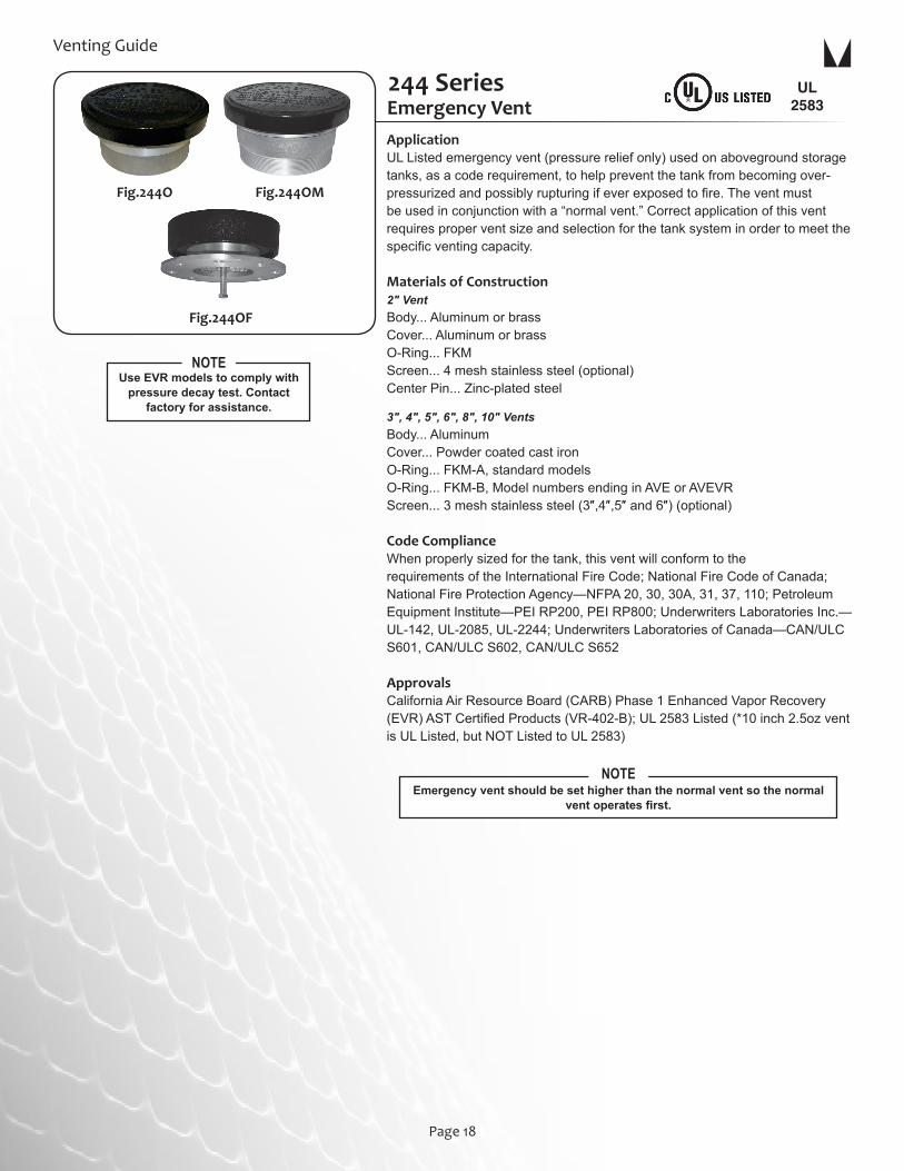
Emergency vent should be set higher than the normal vent so the normal vent operates first.
NOTE
Use EVR models to comply with pressure decay test. Contact
factory for assistance.
NOTE
Emergency VentApplicationULListedemergencyvent(pressurereliefonly)usedonabovegroundstoragetanks,asacoderequirement,tohelppreventthetankfrombecomingover-pressurizedandpossiblyrupturingifeverexposedtofire.Theventmustbeusedinconjunctionwitha“normalvent.”Correctapplicationofthisventrequiresproperventsizeandselectionforthetanksysteminordertomeetthespecificventingcapacity.
Materials of Construction2″ VentBody...AluminumorbrassCover...AluminumorbrassO-Ring...FKMScreen...4meshstainlesssteel(optional)CenterPin...Zinc-platedsteel
3″, 4″, 5″, 6″, 8″, 10″ VentsBody...AluminumCover...PowdercoatedcastironO-Ring...FKM-A,standardmodelsO-Ring...FKM-B,ModelnumbersendinginAVEorAVEVRScreen...3meshstainlesssteel(3″,4″,5″and6″)(optional)
Code ComplianceWhenproperlysizedforthetank,thisventwillconformtotherequirementsoftheInternationalFireCode;NationalFireCodeofCanada;NationalFireProtectionAgency—NFPA20,30,30A,31,37,110;PetroleumEquipmentInstitute—PEIRP200,PEIRP800;UnderwritersLaboratoriesInc.—UL-142,UL-2085,UL-2244;UnderwritersLaboratoriesofCanada—CAN/ULCS601,CAN/ULCS602,CAN/ULCS652
ApprovalsCaliforniaAirResourceBoard(CARB)Phase1EnhancedVaporRecovery(EVR)ASTCertifiedProducts(VR-402-B);UL2583Listed(*10inch2.5ozventisULListed,butNOTListedtoUL2583)
244 Series
Fig.244OF
Fig.244OMFig.244O
Page 18

Morrison Bros. Co.
Page 19
WARNING: The244emergencyventisfor"emergencypressurereliefonly"andmustbeusedinconjunctionwitha"normalvent"orpressurevacuumventsuchasaMorrisonFig.354,748,948A,749or922.The244emergencyventmustbeproperlysizedandselectedforeachspecifictankapplicationinordertomeettheproper"ventingcapacity"requirements.SeetheMorrisonVentGuideforfurtherinstructions.
WARNING: DO NOT FILL OR UNLOAD FUEL FROM A STORAGE TANK UNLESS IT IS CERTAIN THAT THE TANK VENTS WILL OPERATE PROPERLY.MorrisontankventsaredesignedonlyforuseonshopfabricatedatmospherictankswhichhavebeenbuiltandtestedinaccordancewithUL142,NFPA30&30A,andAPI650andinaccordancewithallapplicablelocal,stateandfederallaws.Innormaloperation,dustanddebriscanaccumulateinventopeningsandblockairpassages.Certainatmosphericconditionssuchasasuddendropintemperature,belowfreezingtemperatures,andfreezingraincancausemoisturetoentertheventandfreezewhichcanrestrictinternalmovementofventmechanismsandblockairpassages.Allstoragetankventairpassagesmustbecompletelyfreeofrestrictionandallventmechanismsmusthavefreemovementinordertoinsureproperoperation.Anyrestrictionofairflowcancauseexcessivepressureorvacuumtobuildupinthestoragetank,whichcanresultinstructuraldamagetothetank,fuelspillage,propertydamage,fire,injury,anddeath.Monthlyinspection,andimmediateinspectionduringfreezingconditions,bysomeonefamiliarwiththeproperoperationofstoragetankvents,isrequiredtoinsureventingdevicesarefunctioningproperlybeforefillingorunloadingatank.NormalventssuchaspressurevacuumandupdraftventsforabovegroundstoragetanksshouldbesizedaccordingtoNFPA30(2018)21.4.3
Item Number Size
Venting Capacity
(*Est. SCFH @ 2.5 PSI)
Mounting Connection
Opening Pressure Setting(oz/in2)
Weight(lbs)
244OM-0020 AV2"
31,917 Male NPT 8 1.0244OMA0030AVEVR 31,917 Male NPT 16 1.0
244O--0050 AV
3"
60,994 Female NPT 8 7.0244O--0060 AV 60,994 Female NPT 16 11.50244O--0060AVEVR 60,994 Female NPT 16 11.50244OM-0050 AV 60,994 Male NPT 8 6.40244OM-0060 AV 60,994 Male NPT 16 11.0244OM-0060AVEVR 60,994 Male NPT 16 11.0
244O--0100 AV
4"
131,700 Female NPT 8 10.0244O--0170 AV 131,700 Female NPT 16 18.0244O--0170AVEVR 131,700 Female NPT 16 18.0244OF-0170 AV 131,700 Flanged 16 20.0244OF-0170AVEVR 131,700 Flanged 16 20.0244OF-0600 AV 131,700 Flanged 8 11.0244OF-0600 AVE 131,700 Flanged 8 11.0244OM-0100 AV 131,700 Male NPT 8 10.0244OM-0170 AV 131,700 Male NPT 16 19.0244OM-0170AVEVR 131,700 Male NPT 16 19.0Flange = 9” OD; eight (8) .75” diameter holes on 7.5” diameter B.C.
244O--0800 AV
5"
190,087 Female NPT 8 14.0244O--0900 AV 190,087 Female NPT 16 27.0244O--0900AVEVR 190,087 Female NPT 16 27.0244OM-0800 AV 190,087 Male NPT 8 15.0244OM-0900 AV 190,087 Male NPT 16 28.0244OM-0900AVEVR 190,087 Male NPT 16 28.0
Item Number Size
Venting Capacity
(*Est. SCFH @ 2.5 PSI)
Mounting Connection
Opening Pressure Setting(oz/in2)
Weight(lbs)
244O--0200 AV
6"
299,684 Female NPT 8 20.0244O--0200AVEVR 299,684 Female NPT 8 20.0244O--0400 AV 299,684 Female NPT 16 36.0244O--0400AVEVR 299,684 Female NPT 16 36.0244OF-0050 AV 299,684 Flanged 8 22.0244OF-0050AVEVR 299,684 Flanged 8 22.0244OF-0075 AV 299,684 Flanged 16 38.0244OF-0075AVEVR 299,684 Flanged 16 38.0244OM-0200 AV 299,684 Male NPT 8 21.0244OM-0200AVEVR 299,684 Male NPT 8 21.0244OM-0400 AV 299,684 Male NPT 16 37.0244OM-0400AVEVR 299,684 Male NPT 16 37.0Flange = 11” OD ; eight (8) .88” Diameter holes on 9.5” diameter B.C.
244O--0600 AV
8"
503,517 Female NPT 8 33.0244O--0600 AVE 503,517 Female NPT 8 33.0244O--0700 AV 503,517 Female NPT 16 62.0244O--0700 AVEVR 503,517 Female NPT 16 62.0244OF-0100 AV 503,517 Flanged 8 33.0244OF-0100AVEVR 503,517 Flanged 8 33.0244OF-0200 AV 503,517 Flanged 16 67.0244OF-0200AVEVR 503,517 Flanged 16 67.0244OM-0600 AV 503,517 Male NPT 8 34.0244OM-0600 AVEVR 503,517 Male NPT 8 34.0244OM-0700 AV 503,517 Male NPT 16 63.0244OM-0700 AVEVR 503,517 Male NPT 16 63.0Flange = 14” OD ; eight (8) .88” Diameter holes on 11.75” diameter B.C.
244OF-0300 AV
10"
881,670 Flanged 2.5 25.0244OF-0400 AV 890,275 Flanged 8 57.0244OF-0400AVEVR 890,275 Flanged 8 57.0244OF-0500 AV 890,275 Flanged 16 103.0244OF-0500AVEVR 890,275 Flanged 16 103.0

Page 20
Venting Guide
Lightweight Emergency Vent245 Series
ApplicationThislightweight,spring-loadedemergencyvent(pressurereliefonly)isusedonabovegroundstoragetanks,asacoderequirement,tohelppreventthetankfrombecomingover-pressurizedandpossiblyrupturingifeverexposedtofire.Thisventmustbeusedinconjunctionwitha“normalvent.”Correctapplicationofthisventrequiresproperventsizeandselectionforthetanksysteminordertomeetthespecificventingcapacity.
Materials of ConstructionBody...AluminumCover...AluminumSeat...FKMBolt...ZincplatedsteelSpring...Stainlesssteel
Code ComplianceWhenproperlysizedforthetank,thisventwillconformtotherequirementsoftheInternationalFireCode;NationalFireCodeofCanada;NationalFireProtectionAgency—NFPA30,30A,31,37,110;PetroleumEquipmentInstitute—PEIRP200,PEIRP800;UnderwritersLaboratoriesInc.—UL-142,UL-2085,UL-2244;UnderwritersLaboratoriesofCanada—CAN/ULCS601,CAN/ULCS602,CAN/ULCS652
ApprovalsUL2583Listed
UL 2583
Emergency vent should be set higher than the normal vent so the normal
vent operates first.
NOTE
Item Number Size
Venting Capacity
(*Est. SCFH @ 2.5 PSI)
Mounting Connection
Opening Pressure Setting
(oz/in2) Height Bolt GapWeight
(lbs)245M--0200 AV 2” 31,917 Male NPT 8 1.50" 1.60" 0.50
245---0300 AV3”
67,162 Female NPT 8 2.80" 0.90" 2.80245M--0300 AV 67,162 Male NPT 8 3.60" < ¼" 2.50
245---0400 AV4”
129,369 Female NPT 8 3.10" 2.50" 3.30245M--0400 AV 129,369 Male NPT 8 5.40" < ¼" 4.50245F--0400 AV † 129,369 Flanged 8 2.50" 3.00" 6.00
245---0600 AV6”
331,750 Female NPT 8 3.40" 2.60" 5.50245M--0600 AV 331,750 Male NPT 8 5.40" 0.20" 6.20245F--0600 AV † 331,750 Flanged 8 2.90" 3.20" 9.10
245--0800 AV8”
527,441 Female NPT 8 4.50" 1.50" 9.20245M--0800 AV 527,441 Male NPT 8 5.70" 0.40" 10.10245F--0800 AV † 527,441 Flanged 8 3.30" 2.90" 14.50
245F--1000 AV † 10” 972,110 Flanged 8 2.80" 6.00" 20.00
245F
245M 245
WARNING: DO NOT FILL OR UNLOAD FUEL FROM A STORAGE TANK UNLESS IT IS CERTAIN THAT THE TANK VENTS WILL OPERATE PROPERLY.MorrisontankventsaredesignedonlyforuseonshopfabricatedatmospherictankswhichhavebeenbuiltandtestedinaccordancewithUL142,NFPA30&30A,andAPI650andinaccordancewithallapplicablelocal,stateandfederallaws.Innormaloperation,dustanddebriscanaccumulateinventopeningsandblockairpassages.Certainatmosphericconditionssuchasasuddendropintemperature,belowfreezingtemperatures,andfreezingraincancausemoisturetoentertheventandfreezewhichcanrestrictinternalmovementofventmechanismsandblockairpassages.Allstoragetankventairpassagesmustbecompletelyfreeofrestrictionandallventmechanismsmusthavefreemovementinordertoinsureproperoperation.Anyrestrictionofairflowcancauseexcessivepressureorvacuumtobuildupinthestoragetank,whichcanresultinstructuraldamagetothetank,fuelspillage,propertydamage,fire,injury,anddeath.Monthlyinspection,andimmediateinspectionduringfreezingconditions,bysomeonefamiliarwiththeproperoperationofstoragetankvents,isrequiredtoinsureventingdevicesarefunctioningproperlybeforefillingorunloadingatank.NormalventssuchaspressurevacuumandupdraftventsforabovegroundstoragetanksshouldbesizedaccordingtoNFPA30(2018)21.4.3
WARNING: The245lightweightemergencyventisfor"emergencypressurereliefonly"andmustbeusedinconjunctionwitha"normalvent"orpressurevacuumventsuchasaMorrisonFig.354,748,948A,749or922.The245lightweightemergencyventmustbeproperlysizedandselectedforeachspecifictankapplicationinordertomeettheproper"ventingcapacity"requirements.SeetheMorrisonVentGuideforfurtherinstructions.

Page 20 Page 21
Morrison Bros. Co.
Flanged Adaptor
ApplicationFlangeadaptorsareweldedtotanktopopeningsinabovegroundstoragetankscreatingaflangedemergencyventconnection.
Features• Pre-drilledforeasyinstallationofemergencyvent• Gaskets,nuts,andboltsareavailable
Materials of ConstructionBody...Carbonsteel
244A
244A
Item Number Size OAL Weight (lbs)244A--0400 1A 4” (eight ¾" holes on 7½" B.C.) 5" 10.0244A--0000 1A 6” (eight ⅞” holes on 9½” B.C.) 8" 12.0244A--0100 1A 8” (eight ⅞” holes on 11¾” B.C.) 8" 19.0244A--0200 1A 10” (twelve 1” holes on 14¼” B.C.) 10" 20.0
244NT.O.E. T.B.E.
Item Number Size Threads Weight (lbs)244N--0100 1N 4″ x 8″ T.O.E 7.0244N--0200 1N 6″ x 8″ T.O.E 13.0244N--0300 1N 8″ x 12″ T.O.E 28.0244N--0600 1N 4″ x 8″ T.B.E 7.0244N--0700 1N 6″ x 8″ T.B.E 13.0244N--0800 1N 8″ x 12″ T.B.E 28.0244N--1000 1N 8″ x 8″ T.O.E 20.0244N--1100 1N 8″ x 8″ T.B.E 20.0
Pipe Nipple
Femalethreadsdesignedtoconvertamalethreadedpipenippletoa150#raisedfaceflangeconnection.
Materials of ConstructionCastironwithfemaleNPT“centerport”I.D.
244N
Companion Flange
Thiscompanionflangehasfemalethreadsandisdesignedtoconvertamalethreadedpipenippletoa150#raisedfaceflangeconnection.
Materials of ConstructionBody...CastironwithfemaleNPT“centerport”I.D.
244C
244C
Item Number Size Weight (lbs)244C--0100 1F 8” (eight ⅞” holes on 11¾” B.C. w/8” NPT I.D.) 27.0244C--0200 1F 10” (twelve 1” holes on 14¼” B.C. w/10” NPT I.D.) 36.0

Page 22
Venting Guide
Normal vents such as pressure vacuum and updraft vents for aboveground storage tanks
should be sized according to NFPA 30 (2018) 21.4.3.3
NOTE
Item Number SizeVenting Capacity (SCFH) (@2.5 PSI)
Pressure Setting (oz/in2)
Vacuum Setting (oz/in2) Weight (lbs)
948A--0200 AV 2" 36,720 2.5" to 6" W.C. 6" to 10" W.C. 7.70Meets the requirements of EPA 40 CFR part 63 for Gasoline Dispensing Facilities.
Pressure/Vacuum Vent948A
ApplicationThe948Apressurevacuumventisdesignedforinstallationontopoftheventpipeofanabovegroundorundergroundstoragetank.Thepoppetssealvaporsinthetankwhenpressureisequalized.Theventallowsthetankto“breathe”duringfillinganddischargingoperations.
Features• Conservesvapors• Durableconstruction• Easilyreplaceablesealsextendlifeexpectancy• Outlastsotherbrandsduetoextendedservicelife• Operatingtemperature-40°Fto130°F• Full2″orificeformaximumflowrate• Compatiblewithgasoline,ethanol(toE-85),andbiodiesel(toB-20)
Leak Rates and Settings• Pressureleakrate:[email protected]”WC• Vacuumleakrate:[email protected]:WC• Openingpressure:2.5”to6.0”WC• Openingvacuum:6.0”to10.0”WC
Estimated Flow Rates• 36,[email protected]• 8,[email protected]
Materials of ConstructionBody...AnodizedaluminumSeals...FKMScreens...StainlesssteelHandle...StainlesssteelRainguard...Aluminum
Certifications and ListingsUL2583Listed;948APressureVacuumVentsmeettherequirementsofEPA40CFRpart63forGasolineDispensingFacilities;MissouriAirConservationCommissionApprovedforRule10CSR10.2.260and10.5.220
UL 2583
948A
WARNING: DO NOT FILL OR UNLOAD FUEL FROM A STORAGE TANK UNLESS IT IS CERTAIN THAT THE TANK VENTS WILL OPERATE PROPERLY.MorrisontankventsaredesignedonlyforuseonshopfabricatedatmospherictankswhichhavebeenbuiltandtestedinaccordancewithUL142,NFPA30&30A,andAPI650andinaccordancewithallapplicablelocal,stateandfederallaws.Innormaloperation,dustanddebriscanaccumulateinventopeningsandblockairpassages.Certainatmosphericconditionssuchasasuddendropintemperature,belowfreezingtemperatures,andfreezingraincancausemoisturetoentertheventandfreezewhichcanrestrictinternalmovementofventmechanismsandblockairpassages.Allstoragetankventairpassagesmustbecompletelyfreeofrestrictionandallventmechanismsmusthavefreemovementinordertoinsureproperoperation.Anyrestrictionofairflowcancauseexcessivepressureorvacuumtobuildupinthestoragetank,whichcanresultinstructuraldamagetothetank,fuelspillage,propertydamage,fire,injury,anddeath.Monthlyinspection,andimmediateinspectionduringfreezingconditions,bysomeonefamiliarwiththeproperoperationofstoragetankvents,isrequiredtoinsureventingdevicesarefunctioningproperlybeforefillingorunloadingatank.NormalventssuchaspressurevacuumandupdraftventsforabovegroundstoragetanksshouldbesizedaccordingtoNFPA30(2018)21.4.3

Page 22 Page 23
Morrison Bros. Co.
Normal vents such as pressure vacuum and updraft vents for aboveground storage tanks
should be sized according to NFPA 30 (2018) 21.4.3.3
NOTE
*Consult Price List for other options including male threaded dryer connection and female threaded pressure discharge hood.
Item Number Size
Venting Capacity (SCFH)
(@ 2.5 PSI)
Pressure Setting (oz./in2)
Vacuum Setting
(oz/in2)Weight
(lbs)748A--0100 AV
2″
20,200 2.0 1.0 6.50748A--0200 AV 20,200 4.0 1.0 7.15748A--0300 AV 20,200 6.0 1.0 7.55748A--0400 AV 20,200 8.0 1.0 8.15748A--0500 AV 18,600 12.0 1.0 9.30748A--0600 AV 18,600 16.0 1.0 10.35
748A--3100 AV
3″
43,000 2.0 1.0 9.75748A--3200 AV 43,000 4.0 1.0 11.15748A--3300 AV 43,000 6.0 1.0 12.15748A--3400 AV 43,000 8.0 1.0 13.10748A--3500 AV 40,000 12.0 1.0 15.30748A--3600 AV 40,000 16.0 1.0 17.75
WARNING: DO NOT FILL OR UNLOAD FUEL FROM A STORAGE TANK UNLESS IT IS CERTAIN THAT THE TANK VENTS WILL OPERATE PROPERLY.MorrisontankventsaredesignedonlyforuseonshopfabricatedatmospherictankswhichhavebeenbuiltandtestedinaccordancewithUL142,NFPA30&30A,andAPI650andinaccordancewithallapplicablelocal,stateandfederallaws.Innormaloperation,dustanddebriscanaccumulateinventopeningsandblockairpassages.Certainatmosphericconditionssuchasasuddendropintemperature,belowfreezingtemperatures,andfreezingraincancausemoisturetoentertheventandfreezewhichcanrestrictinternalmovementofventmechanismsandblockairpassages.Allstoragetankventairpassagesmustbecompletelyfreeofrestrictionandallventmechanismsmusthavefreemovementinordertoinsureproperoperation.Anyrestrictionofairflowcancauseexcessivepressureorvacuumtobuildupinthestoragetank,whichcanresultinstructuraldamagetothetank,fuelspillage,propertydamage,fire,injury,anddeath.Monthlyinspection,andimmediateinspectionduringfreezingconditions,bysomeonefamiliarwiththeproperoperationofstoragetankvents,isrequiredtoinsureventingdevicesarefunctioningproperlybeforefillingorunloadingatank.NormalventssuchaspressurevacuumandupdraftventsforabovegroundstoragetanksshouldbesizedaccordingtoNFPA30(2018)21.4.3
748A
Pressure/Vacuum Vent
ApplicationThispressurevacuumventisdesignedforinstallationontopoftheventpipeofanabovegroundorundergroundstoragetank.Poppetssealvaporsinthetankwhenpressureisequalized.Theventallowsthetankto"breathe"duringfillinganddispensingoperations.
Features• DirectsvaporsoutwardandupwardincompliancewithNFPA30• Tri-polardesignformountingexhausthoodinanyofthreepositions• Optionaldryerconnectionsaccommodatetheinstallationofdesiccantdryersonvacuumconnection
• Optionalpressuredischargehoodfacilitatespipingpressurerelieftodesireddischargepoint• Settingsareapproximate
Materials of ConstructionBodyandhood…AluminumSeats...PassivatedaluminumPoppets…BrassScreens…Stainlesssteel
748A Series

Page 24
Venting Guide
Item Number Size
Pressure Setting (oz./in2)
Vacuum Setting
(oz/in2)
Venting Capacity (SCFH)
(@ 2.5 PSI)Weight
(lbs)748ALT0100 AV 2" 8.0 1.0 20,200 5.50748ALT0200 AV 2" 16.0 1.0 18,000 5.50748ALT0300 AV 2" 32.0 1.0 -- 5.50
*Consult Price List for other options including male threaded dryer connection and female threaded pressure discharge hood.
748ALT
Pressure/Vacuum Vent748ALT
ApplicationThe748ALTpressurevacuumventvalveisusedwithaqua-ammoniaandag-chemicalproductsallowingthetankto"breathe"duringfillinganddispensingoperations.Pressureandvacuumpoppetssealvaporsinthetankwhenpressureisequalized.
Features• Settingsareapproximate• Conservesvapors• Tri-polardesignformountingexhausthoodinanyofthreepositions
Materials of ConstructionBodyandhood...AluminumSeatsandpoppets...PTFEcoatedaluminumScreens...Stainlesssteel
WARNING: DO NOT FILL OR UNLOAD FUEL FROM A STORAGE TANK UNLESS IT IS CERTAIN THAT THE TANK VENTS WILL OPERATE PROPERLY.MorrisontankventsaredesignedonlyforuseonshopfabricatedatmospherictankswhichhavebeenbuiltandtestedinaccordancewithUL142,NFPA30&30A,andAPI650andinaccordancewithallapplicablelocal,stateandfederallaws.Innormaloperation,dustanddebriscanaccumulateinventopeningsandblockairpassages.Certainatmosphericconditionssuchasasuddendropintemperature,belowfreezingtemperatures,andfreezingraincancausemoisturetoentertheventandfreezewhichcanrestrictinternalmovementofventmechanismsandblockairpassages.Allstoragetankventairpassagesmustbecompletelyfreeofrestrictionandallventmechanismsmusthavefreemovementinordertoinsureproperoperation.Anyrestrictionofairflowcancauseexcessivepressureorvacuumtobuildupinthestoragetank,whichcanresultinstructuraldamagetothetank,fuelspillage,propertydamage,fire,injury,anddeath.Monthlyinspection,andimmediateinspectionduringfreezingconditions,bysomeonefamiliarwiththeproperoperationofstoragetankvents,isrequiredtoinsureventingdevicesarefunctioningproperlybeforefillingorunloadingatank.NormalventssuchaspressurevacuumandupdraftventsforabovegroundstoragetanksshouldbesizedaccordingtoNFPA30(2018)21.4.3

Page 24 Page 25
Morrison Bros. Co.
749
Morrison 749 P/V vent must only be used in conjunction with motor fueling and/or low capacity flow.
Fluid handling in lines larger than that used for retail service stations
can cause tank to rupture or implode.
NOTE
WARNING: DO NOT FILL OR UNLOAD FUEL FROM A STORAGE TANK UNLESS IT IS CERTAIN THAT THE TANK VENTS WILL OPERATE PROPERLY.MorrisontankventsaredesignedonlyforuseonshopfabricatedatmospherictankswhichhavebeenbuiltandtestedinaccordancewithUL142,NFPA30&30A,andAPI650andinaccordancewithallapplicablelocal,stateandfederallaws.Innormaloperation,dustanddebriscanaccumulateinventopeningsandblockairpassages.Certainatmosphericconditionssuchasasuddendropintemperature,belowfreezingtemperatures,andfreezingraincancausemoisturetoentertheventandfreezewhichcanrestrictinternalmovementofventmechanismsandblockairpassages.Allstoragetankventairpassagesmustbecompletelyfreeofrestrictionandallventmechanismsmusthavefreemovementinordertoinsureproperoperation.Anyrestrictionofairflowcancauseexcessivepressureorvacuumtobuildupinthestoragetank,whichcanresultinstructuraldamagetothetank,fuelspillage,propertydamage,fire,injury,anddeath.Monthlyinspection,andimmediateinspectionduringfreezingconditions,bysomeonefamiliarwiththeproperoperationofstoragetankvents,isrequiredtoinsureventingdevicesarefunctioningproperlybeforefillingorunloadingatank.NormalventssuchaspressurevacuumandupdraftventsforabovegroundstoragetanksshouldbesizedaccordingtoNFPA30(2018)21.4.3
Pressure/Vacuum Vent
ApplicationPressurevacuumventsareinstalledonthetopofundergroundandlowvolumeabovegroundstoragetankventpipes.Ventallowstankto“breathe”duringfillinganddischargingoperations.Pressureandvacuumpoppetssealvaporsintankwhenpressureisequalized.Settingsareapproximate.
Features• Screenprotectsthetankfromdebrisandinsects• Integratedinternaldrainportchannelswaterawayfromthetank• VentvaporsupandoutwardperNFPA30• Conservesfuel• CertifiedSCFHratings
Materials of ConstructionBodyandhood...AnodizedaluminumPressurepoppet...AnodizedaluminumVacuumpoppet...BrassvacuumBodyseal...Buna-NScreen...40meshstainlesssteelSprings...StainlesssteelSetscrews...Zinc-platedsteel
Certifications and ListingsCARB95-14(749CRB0500model);CARB95-15(749CRB0600model);CARB96-19(749CRBS0600model);749CRBPressureVacuumVents(models749CRB0600AV,749CRB1600AV,749CRBS0600AV,and749CRBS1600AV)meettherequirementsofEPA40CFRpart63forGasolineDispensingFacilities
749 Series
Meet the requirements of EPA 40 CFR part 63 for Gasoline Dispensing Facilities.♦
Item Number Size ConnectionPressure Setting
(oz./in2)Vacuum Setting
(oz./in2)Venting Capacity (SCFH)
(@ 2.5 PSI) Weight (lbs)749---0100 AV 2″ Threaded 8.0 0.5 8,500 1.0749---0200 AV 2″ Threaded 12.0 0.5 8,500 1.0749---1100 AV 3″ Threaded 8.0 0.5 8,500 1.55749---1200 AV 3″ Threaded 12.0 0.5 8,500 1.55
749S--0100 AV 2″ Slip-on 8.0 0.5 8,500 1.0749S--0200 AV 2″ Slip-on 12.0 0.5 8,500 1.0749S--1100 AV 3″ Slip-on 8.0 0.5 8,500 1.55749S--1200 AV 3″ Slip-on 12.0 0.5 8,500 1.55
749CRB0500 AV 2″ Threaded 8.0 5.0 11,000 1.45749CRB0600 AV 2″ Threaded 3″ W.C. 8″ W.C. 11,000 1.95749CRB1500 AV 3″ Threaded 8.0 5.0 8,500 1.65749CRB1600 AV 3″ Threaded 3″ W.C. 8″ W.C. 11,000 1.65
749CRBS600 AV 2″ Slip-on 3″ W.C. 8″ W.C. 11,000 1.45749CRBS1600 AV 3″ Slip-on 3″ W.C. 8″ W.C. 11,000 1.95♦
♦
♦
♦

Page 26
Venting Guide
922
922 not for use on vapor recovery systems.
NOTE
Item Number SizePressure Setting
(oz/in2)Venting Capacity (SCFH) (@ 2.5 PSI)
dB Rating*
Weight (lbs)
922---0200 AA 2″ 8 oz 30,300 120 8.50922---0300 AA 3″ 8 oz 43,020 120 6.30922---0400 AA 2″ 6 oz 30,120 110 8.50922---0500 AA 3″ 6 oz 44,160 105 6.30
WARNING: DO NOT FILL OR UNLOAD FUEL FROM A STORAGE TANK UNLESS IT IS CERTAIN THAT THE TANK VENTS WILL OPERATE PROPERLY.MorrisontankventsaredesignedonlyforuseonshopfabricatedatmospherictankswhichhavebeenbuiltandtestedinaccordancewithUL142,NFPA30&30A,andAPI650andinaccordancewithallapplicablelocal,stateandfederallaws.Innormaloperation,dustanddebriscanaccumulateinventopeningsandblockairpassages.Certainatmosphericconditionssuchasasuddendropintemperature,belowfreezingtemperatures,andfreezingraincancausemoisturetoentertheventandfreezewhichcanrestrictinternalmovementofventmechanismsandblockairpassages.Allstoragetankventairpassagesmustbecompletelyfreeofrestrictionandallventmechanismsmusthavefreemovementinordertoinsureproperoperation.Anyrestrictionofairflowcancauseexcessivepressureorvacuumtobuildupinthestoragetank,whichcanresultinstructuraldamagetothetank,fuelspillage,propertydamage,fire,injury,anddeath.Monthlyinspection,andimmediateinspectionduringfreezingconditions,bysomeonefamiliarwiththeproperoperationofstoragetankvents,isrequiredtoinsureventingdevicesarefunctioningproperlybeforefillingorunloadingatank.NormalventssuchaspressurevacuumandupdraftventsforabovegroundstoragetanksshouldbesizedaccordingtoNFPA30(2018)21.4.3
Combination Vent/Overfill Alarm922
ApplicationTheaudiblealarmwhistleswhentheliquidlevelintheabovegroundstoragetankreachesthepresetlevel.Thepressurevacuumventallowsthetankto“breathe”duringfillinganddispensingoperations.
Features• Functionsasbothapressurevacuumventandaudiblealarmwhileutilizingasingle2″or3″tankopening.Installsonthetopoftheventpipe,generally12feetabovegrade
• 105to120decibelwhistlealarm(measuredatadistanceof1footwithafillrateof90GPM)• Fullymechanicalalarmdoesnotrequireelectricityorbatteries• Thealarmlevelcanbesettoactivateatanyliquidlevelbyadjustingthecablelengthtothefloatdevice
• Minimumfillrateof20GPMrequiredforalarmtooperate
Materials of ConstructionBody...AnodizedaluminumScreens...StainlesssteelRainguard...AluminumSeals...FKMBall...PTFEFloat...Stainlesssteel
Certifications and ListingsFloridaDEPEQ-227
WARNING: Allemergencyvents,fillconnections,tankopenings,andpipingconnectionsmustbeairtight.Alarm/ventairwaymustbefreeofanyobstructionsuchasdirtoricewhenfillingorunloadingtank.Emergencyventshouldbesetatleast2oz.higherthancombinationvent.

Page 26 Page 27
Morrison Bros. Co.
WARNING: DO NOT FILL OR UNLOAD FUEL FROM A STORAGE TANK UNLESS IT IS CERTAIN THAT THE TANK VENTS WILL OPERATE PROPERLY.MorrisontankventsaredesignedonlyforuseonshopfabricatedatmospherictankswhichhavebeenbuiltandtestedinaccordancewithUL142,NFPA30&30A,andAPI650andinaccordancewithallapplicablelocal,stateandfederallaws.Innormaloperation,dustanddebriscanaccumulateinventopeningsandblockairpassages.Certainatmosphericconditionssuchasasuddendropintemperature,belowfreezingtemperatures,andfreezingraincancausemoisturetoentertheventandfreezewhichcanrestrictinternalmovementofventmechanismsandblockairpassages.Allstoragetankventairpassagesmustbecompletelyfreeofrestrictionandallventmechanismsmusthavefreemovementinordertoinsureproperoperation.Anyrestrictionofairflowcancauseexcessivepressureorvacuumtobuildupinthestoragetank,whichcanresultinstructuraldamagetothetank,fuelspillage,propertydamage,fire,injury,anddeath.Monthlyinspection,andimmediateinspectionduringfreezingconditions,bysomeonefamiliarwiththeproperoperationofstoragetankvents,isrequiredtoinsureventingdevicesarefunctioningproperlybeforefillingorunloadingatank.NormalventssuchaspressurevacuumandupdraftventsforabovegroundstoragetanksshouldbesizedaccordingtoNFPA30(2018)21.4.3
351S with 748A
Flame Arrester
ApplicationFlamearrestersprovideapositivebarrierthatdetersflamesfrompassingthroughthepressurevacuumventlineintoastoragetank’svaporspace.
Features• DirectsvaporsoutwardandupwardinaccordancewithNFPA30• Protectstheventlinefromdebrisandinsects• Tri-polarmountingscrewsformountingexhausthoodinanyofthreepositions• Optionalpressuredischargehoodfacilitatespipingpressurerelieftodesireddischargepoint
Materials of Construction351SBodyandcover...CastironArrestergridhousing...BrassArresterplates...Stainlesssteel
748ABodyandhood...AluminumPoppetsandseats...BrassScreens...Stainlesssteel
351S & 748A
WARNING: Donotusewithacetylene,carbondisulfide,etheleneoxideorhydrogengases.Forusewithnormalhydrocarbonflamessuchasgasolineinair.Routineinspectionisrequiredtoensureairwaysareclearandfreeofdebris.Blockedairwayscancausestructuraldeformationofthetank.
Item Number SizePressure Setting
(oz./in2)Vacuum Setting
(oz./in2)Venting Capacity (SCFH)
(@2.5 PSI)Weight
(lbs)351S--0200 AV 2″ 2.0 1.0 15,500 42.0351S--0300 AV 2″ 4.0 1.0 15,500 42.50351S--0400 AV 2″ 6.0 1.0 15,500 42.75351S--0500 AV 2″ 8.0 1.0 15,500 43.50351S--0600 AV 2″ 12.0 1.0 13,000 44.50351S--0700 AV 2″ 16.0 1.0 13,000 45.75
*Consult Price List for other options including male threaded dryer connection and female threaded pressure discharge hood.

Page 28
Venting Guide
*NFPA 70, the National Electrical Code, lists or defines hazardous gases, vapors, and dusts
by “Groups.” Consult these resources for information on Group D fluids.
For petroleum storage tanks containing Group D* fluids.
NOTE
Item Number SizeVenting Capacity (SCFH) (@2.5 PSI)
Weight (lbs)
352---0200 AA 2" 57,000 8.30352---0300 AA 3" 117,000 16.20
End-of-Line, Open Air Deflagration Flame Arrester352
ApplicationEnd-of-Lineflamearrestersaredesignedtobeinstalledattheendconnectionofatankventline.Theflamearresterprovidesaprotectionbarrierthatdetersaflamegeneratedfromasourceoutsideofthetankfromflashingthroughtheventintothevaporspaceofthetank.
Features• 304stainlessarresterplatesprovidelongtermcorrosionresistanceanddurability• Easyaccessforvisualinspectionandperiodicmaintenance• Full2”and3”NPTventlineairflowcapacity• Water-resistantcovershedswaterawayfromtheventline
Materials of ConstructionBase….356temperedaluminumCover…AluminumArresterplates…304stainlesssteelThreadedhardware…18-8stainlesssteel
Certifications and ListingsUL525Listed–StandardforFlameArresters–Edition8
Fig. 352

Page 28 Page 29
Morrison Bros. Co.
Open vents will allow unrestricted evaporation of
product.
NOTE
Item Number Size (slip-on)Venting Capacity (SCFH)
(@ 2.5 PSI)Weight
(lbs)354---0100 AV 1½″ 27,650 0.75354---0200 AV 2″ 27,650 0.75354---0300 AV 3″ 59,000 1.50354---0400 AV 4″ 116,900 2.25
Item Number Size Weight (lbs)155---0100 AV ¾″ 0.25155---0200 AV 1″ 0.50155---0300 AV 1¼″ 0.50155---0400 AV 1½″ 0.75155---0500 AV 2″ 1.0155---0600 AV 3″ 2.50
155S--0100 AV ¾″ 0.25155S--0200 AV 1″ 0.50155S--0300 AV 1¼″ 0.50155S--0400 AV 1½″ 0.75155S--0500 AV 2″ 1.0155S--0600 AV 3″ 2.50
354
Updraft Vent
ApplicationAtmosphericupdraftventsareinstalledonthetopofstoragetankventpipesonundergroundandabovegroundfuelstoragetanks.
Features• DirectsvaporsoutwardandupwardinaccordancewithNFPA30• Protectstheventlinefromdebrisandinsects• Water-resistantraincapshedswaterawayfromtheventline• Slip-ondesignwithsetscrewsforeasyinstallation• Internaldrainchannelswaterpenetrationoutthroughweephole
Materials of ConstructionBodyandcap...AluminumdiecastScreen...40meshstainlesssteel
Certifications and ListingsCARB89-12(1½″and2″models)
354 Series
Open vents will allow unrestricted evaporation of
product.
NOTE
155S
Double Outlet Vent
ApplicationDoubleoutlet“T”styleventsareusedtocaptheventopeningonfueloilstoragetanks.
Features• Dualopeningsdirecteddownward• Screenkeepsdebrisoutofthetank• 155hasNPTfemalethreads• 155Sisslip-onwithsetscrew
Materials of ConstructionBody...AluminumScreens...20meshstainlesssteelSetscrew...Zincplatedsteel
155 Series

Page 30
Venting Guide
12 F
t.M
inim
um
Fig.
748
APr
essu
reVa
cuum
Ven
t
Fig.
244
Emer
genc
yVe
nt
Fig.
818
Cloc
kG
auge
(Ala
rm
Fig.
918
)
Fig.
516
or 5
18
Spill
Con
tain
er
Fig.
323
&
323C
Vap
or
Reco
very
Ad
apto
r w
ith C
ap
Fig.
305
CFi
ll Ca
pFi
g. 9
095A
A, 9
095C
, or
909
5X O
verfi
ll Pr
even
tion
Valv
e
Subm
ersi
ble
Pum
p
Fig.
235
or
535
Gat
e Va
lve
Fig.
285
Line
Stra
iner
Fig.
346
Ser
ies
Exte
rnal
Em
erge
ncy
Valv
e
Fig.
710
Sole
noid
Valv
eor
Fig.
912
An
ti-Si
phon
Va
lve
Fig.
78D
IEx
pans
ion
Relie
f Val
ve
Elec
trica
lLi
ne
Fig.
636
Emer
genc
ySh
ut-o
ff Va
lve
Fig.
419
Drop
Tub
e
orFi
g. 9
10
Anti-
Siph
on
Valv
e
Fig.
748A
Pres
sure
Va
cuum
Ven
t
Fig.
244
Emer
genc
y Ve
nt
Fig.
818
Cloc
k Ga
uge
(Alar
m
Fig.
918)
Fig.
323 &
32
3C V
apor
Re
cove
ry
Adap
tor
with
Cap
Fig.
516 o
r 518
Spill
Cont
ainer
Fig.
305C
Fi
ll Cap
Subm
ersib
le Pu
mp
Fig.
9095
AA,
9095
C, o
r 90
95X
Over
fill
Prev
entio
n Va
lveFi
g. 23
5 or
535 G
ate
Valve
Fig.
285
Line
St
rain
er
Fig.
346
Serie
s Ex
tern
al Em
erge
ncy
Valve
Fig.
710
Solen
oid
Valve
orFi
g. 91
2 An
ti-Si
phon
Va
lveor
Fig.
910
Anti-
Siph
on
Valve
Fig.
78DI
Expa
nsio
n Re
lief
Valve
Fig.
419
Drop
Tube
12 ft
.m
inim
um
Elec
trica
l Li
ne
Fig.
636
Emer
genc
y Sh
ut-o
ff Va
lve

Page 30 Page 31
Morrison Bros. Co.
12 F
t. M
inim
umto
Gra
de L
evel
Fig.
715
or 5
15Re
mot
e Sp
illCo
ntai
ner
Fig.
800
A &
800D
C Ad
apto
r w
ith D
ust C
ap
Fig.
691
B Lo
ckin
gBa
ll Va
lve
Fig.
246
Chec
kVa
lve
Fig.
323
& 3
23C
Vapo
r Rec
over
y Ad
apto
r with
Cap
Fig.
918
O
verfi
llAl
arm
Fig.
285
Line
Stra
iner
Fig.
909
5AA
or
9095
X O
verfi
ll Pr
even
tion
Valv
eFi
g. 9
18
Cloc
k G
auge
w
ith A
larm
Fig.
748
A Pr
essu
re
Vacu
um V
ent
Fig.
244
Em
erge
ncy
Vent
Fig.
244
Em
erge
ncy
Vent
(In
ters
titia
l)Su
bmer
sibl
e Pu
mp
Fig.
235
or
535
Gat
e Va
lve
Fig.
285
Li
ne
Stra
iner
Fig.
346
Ser
ies
Exte
rnal
Em
erge
ncy
Valv
eFi
g. 7
10
Sole
noid
Va
lve
orFi
g. 9
12
Anti-
Siph
on
Valv
e
Fig.
78D
I Exp
ansi
on
Relie
f Val
ve
Elec
trica
lLi
ne
Disp
ense
r
Fig.
636
Em
erge
ncy
Shut
-off
Valv
e
Fig.
748A
Pres
sure
Va
cuum
Ven
t
Fig.
244
Emer
genc
y Ve
nt
Fig.
918 C
lock
Ga
uge w
ith
Alar
mSu
bmer
sible
Pum
p
Fig.
9095
AA o
r 90
95X
Over
fill
Prev
entio
n Va
lve
Fig.
235 o
r 53
5 Gat
e Va
lveFi
g. 28
5 Li
ne
Stra
iner
Fig.
346
Serie
s Ex
tern
al Em
erge
ncy
Valve
Fig.
710
Solen
oid
Valve
orFi
g. 91
2 An
ti-Si
phon
Va
lve
Fig.
78DI
Expa
nsio
n Re
lief
Valve
Fig.
636
Emer
genc
y Sh
ut-o
ff Va
lve
Fig.
244
Emer
genc
y Ve
nt(In
ters
titial
)
12 ft
. min
imum
to
gra
de le
vel
Elec
trica
l Li
ne
Disp
ense
r
Fig.
285
Line
St
rain
er
Fig.
246
Chec
k Va
lve
Fig.
515 o
r 715
Re
mot
e Spi
ll Co
ntain
er
Fig.
691B
Lock
ing
Ball V
alve
Fig.
323 &
323C
Va
por R
ecov
ery
Adap
tor w
ith C
ap
Fig.
800A
&
800D
C Ad
apto
r wi
th D
ust C
ap

Page 32
Venting Guide
12 F
t.M
inim
um
Fig.
244
Emer
genc
y Ve
nt
Fig.
818
Cl
ock
Gau
ge
Fig.
922
Com
bina
tion
Pres
sure
Vac
uum
Ve
nt/O
verfi
ll Al
arm
Fig.
516
or
518
Spill
Co
ntai
ner
Fig.
305
C Fi
ll Ca
p
Fig.
909
5AA
or 9
095X
O
verfi
ll Pr
even
tion
Valv
e
Suct
ion
Pum
p
Fig.
419
Drop
Tub
e
Fig.
157
Suct
ion
Pipe
Stra
iner
Fig.
244
Emer
genc
y Ve
nt
Fig.
818
Cloc
k Ga
uge
(Alar
m
Fig.
918)
Fig.
516 o
r 518
Spill
Cont
ainer
Suct
ion
Pum
p
Fig.
9095
AA o
r 90
95X
Over
fill
Prev
entio
n Va
lve
Fig.
419
Drop
Tube
12 ft
.m
inim
um
Fig.
922 C
ombi
natio
nPr
essu
re V
acuu
mVe
nt/O
verfi
ll Alar
m
Fig.
157
Suct
ion
Pipe
Stra
iner
Fig.
539
Diffu
ser

Page 32 Page 33
Morrison Bros. Co.
Fig.
800
A &
800D
C Ad
apto
r with
Du
st C
ap
Fig.
691
B Lo
ckin
gBa
ll Va
lve
Fig.
246
Chec
kVa
lve
Fig.
515
or 7
15
Rem
ote
Spill
Co
ntai
ner
Fig.
419
Drop
Tub
e
Fig.
285
Line
Stra
iner
Fig.
909
5AA
or
9095
X O
verfi
ll Pr
even
tion
Valv
e
Fig.
818
Cloc
k G
auge
Fig.
244
Em
erge
ncy
Vent
(In
ters
titia
l)Fi
g. 2
44
Emer
genc
y Ve
nt
Fig.
922
Com
bina
tion
Pres
sure
Vac
uum
Ve
nt/O
verfi
ll Al
arm
Fig.
235
or
535
Gat
e Va
lve
Fig.
285
Line
Stra
iner
Fig.
346
Ser
ies
Exte
rnal
Em
erge
ncy
Valv
e
Fig.
710
Sole
noid
Va
lve
orFi
g. 9
12
Anti-
Siph
on
Valv
e
Fig.
78D
I Ex
pans
ion
Relie
f Val
ve
12 F
t. M
inim
um to
G
rade
Lev
el
Elec
trica
lLi
ne
Pres
sure
Re
gula
ting
Valv
e (T
okhe
im 5
2)
Fig.
157
Suc
tion
Pipe
Stra
iner
orFi
g. 9
10An
ti-Si
phon
Va
lve
Fig.
244
Emer
genc
y Ve
nt
Fig.
9095
AA o
r 90
95X
Over
fill
Prev
entio
n Va
lve
Fig.
235 o
r 53
5 Gat
e Va
lve
Fig.
285
Line
St
rain
er
Fig.
346
Serie
s Ex
tern
al Em
erge
ncy
Valve
Fig.
78DI
Expa
nsio
n Re
lief
Valve
12 ft
. min
imum
to
gra
de le
vel
Fig.
285
Line
St
rain
er
Fig.
710
Solen
oid
Valve
orFi
g. 91
2 An
ti-Si
phon
Va
lveor
Fig.
910
Anti-
Siph
on
Valve
Elec
trica
l Li
ne
Fig.
691/6
91B
Ball V
alve
Fig.
515 o
r 715
Re
mot
e Spi
ll Co
ntain
er
Fig.
800A
&
800D
C Ad
apto
r wi
th D
ust C
ap
Fig.
244
Emer
genc
y Ve
nt(In
ters
titial
)
Fig.
818
Cloc
k Ga
uge
Fig.
419
Drop
Tube
Fig.
922 C
ombi
natio
nPr
essu
re V
acuu
mVe
nt/O
verfi
ll Alar
m

Page 34
Venting Guide
Fig.
517
or 5
18
Spill
Con
tain
er
Fig.
305
&
305C
Mal
e Q
uick
Di
scon
nect
&
Cap
Fig.
909
5A
Ove
rfill
Prev
entio
n Va
lve
Fig.
818
or 9
18
Cloc
k G
auge
Fig.
244
Em
erge
ncy
Vent
Fig.
244
Em
erge
ncy
Vent
(In
ters
titia
l)12 F
t. M
inim
um
to G
rade
Lev
el
Fig.
354
, Fig
. 922
, or
948
A Co
mbi
natio
n Pr
essu
re
Vacu
umFi
g. 2
46A
Swin
g Ch
eck
Valv
e
Fig.
235
or
535
Gat
e Va
lve
Fig.
285
Li
ne
Stra
iner
Fig.
346
or 4
46 S
erie
s Ex
tern
al E
mer
genc
y Va
lve
Fig.
710
So
leno
id
Valv
e
Fig.
78D
I Ex
pans
ion
Relie
f Val
ve
(Sup
ply)
Fig.
539
Diffu
ser
Fig.
157
Su
ctio
nPi
pe
Stra
iner
or Fig.
334
/ 33
5 Fo
ot
Valv
e
(Gen
erat
or o
r Boi
ler)
(Ret
urn)
Fig.
419
Drop
Tub
e
Fig.
539
Diffu
ser
orFi
g. 9
10 o
r 912
An
ti-Si
phon
Va
lve
orFi
g. 9
58 In
-line
Ch
eck
Valv
e
Fig.
244
Emer
genc
y Ve
nt
Fig.
517 o
r 518
Spill
Cont
ainer
Fig.
9095
A Ov
erfil
l Pr
even
tion
Valve
Fig.
419
Drop
Tube
Fig.
539
Diffu
ser
Fig.
244
Emer
genc
y Ve
nt(In
ters
titial
)
Fig.
354,
Fig.
922 ,
or
948A
Com
bina
tion
Pres
sure
Vac
uum
Fig.
818
Cloc
k Ga
uge
(Alar
m
Fig.
918)
12 ft
. min
imum
to
gra
de le
vel
Fig.
235 o
r 53
5 Gat
e Va
lveFi
g. 28
5 Li
ne
Stra
iner
Fig.
246
Serie
s Swi
ng
Chec
k Valv
eor
Fig.
958
In-li
neCh
eck V
alve
Fig.
346 o
r Fi
g. 44
6 Ser
ies
Exte
rnal
Emer
genc
y Va
lve
Fig.
710
Solen
oid
Valve
orFi
g. 91
2 An
ti-Si
phon
Va
lveor
Fig.
910
Anti-
Siph
on
Valve
Fig.
157
Suct
ion
Pipe
Stra
iner
or Fig.
334/3
35
Foot
Valv
e
Fig.
539
Diffu
ser
Fig.
78DI
Expa
nsio
n Re
lief
Valve
(SUP
PLY)
(RET
URN)
(GEN
ERAT
OR O
R BO
ILER
)

Page 34 Page 35
Morrison Bros. Co.
Abo
vegr
ound
Sto
rage
Tan
k - B
ulk
Stor
age
Fig.
534B
DI
Gate
Valv
e with
Ex
pans
ion
Relie
f
Fig.
272D
I Inte
rnal
Emer
genc
y Valv
e
Fig.
244O
Ser
ies
Emer
genc
y Ven
ts
Fig.
922 C
ombi
natio
n Ve
nt/O
verfi
ll Alar
mor
351 F
lame A
rrest
er/
Pres
sure
Vac
uum
Ven
tor
748A
or 9
48A
Pres
sure
Va
cuum
Ven
t
Fig.
1218
S Ta
nk
Leve
l Sen
sor
Fig.
272D
I Inte
rnal
Emer
genc
y Valv
eFig.
534B
DI
Gate
Valv
e with
Ex
pans
ion
Relie
f
Fig.
246D
RF S
wing
Ch
eck V
alve
Fig.
285F
DI B
otto
m
Clea
n-Ou
t Lin
e St
rain
er
Fig.
515/S
D or
715
(w/ S
S co
mpo
nent
s)
or 71
5S R
emot
e Spi
ll Co
ntain
er

Venting Guide
570 E. 7th Street, P.O. Box 238 | Dubuque, IA 52004-0238t. 563.583.5701 | 800.553.4840 | f. 563.583.5028
[email protected] | www.morbros.com