Installation & Operation Manual 3 General venting - … Approval.pdf · Installation & Operation...
21
16 Two Pipe Sidewall See page 24 for more details IMG01060 PVC/CPVC Concentric Sidewall Models 400 - 600 Only See page 28 for more details Direct venting options - Sidewall Vent IMG01061 3 General venting IMG01062 Two Pipe Vertical See page 31 for more details IMG01064 Vertical Vent, Sidewall Air PVC/CPVC Concentric Vertical Models 400 - 600 Only See page 33 for more details IMG01063 Direct venting options - Vertical Vent Installation & Operation Manual
-
Upload
nguyenkhue -
Category
Documents
-
view
246 -
download
0
Transcript of Installation & Operation Manual 3 General venting - … Approval.pdf · Installation & Operation...
16
Two Pipe SidewallSee page 24 for more details
IMG01060
PVC/CPVC Concentric SidewallModels 400 - 600 Only
See page 28 for more details
Direct venting options - Sidewall Vent
IMG01061
3 General venting
IMG01062
Two Pipe VerticalSee page 31 for more details
IMG01064
Vertical Vent, Sidewall AirPVC/CPVC
Concentric VerticalModels 400 - 600 Only
See page 33 for more details
IMG01063
Direct venting options - Vertical Vent
Installation & Operation Manual
17
3 General venting (continued)
This appliance requires a special venting system. Use only approved stainless steel, PVC, CPVC or polypropylene pipe and fi ttings listed in Tables 3E, 3F, and 3H for vent pipe, and fi ttings. Failure to comply could result in severe personal injury, death, or substantial property damage.
Installation must comply with local requirements and with the National Fuel Gas Code, ANSI Z223.1 for U.S. installations or CSA B149.1 for Canadian installations.
Install vent and combustion air piping
� DANGERThe FTXL boiler must be vented and supplied with combustion and ventilation air as described in this section. Ensure the vent and air piping and the combustion air supply comply with these instructions regarding vent system, air system, and combustion air quality. See also Section 1 of this manual.Inspect fi nished vent and air piping thoroughly to ensure all are airtight and comply with the instructions provided and with all requirements of applicable codes.Failure to provide a properly installed vent and air system will cause severe personal injury or death.
� WARNING
NOTICE
� WARNINGFor closet and alcove installations, CPVC, polypropylene or stainless steel material MUST BE used in a closet/alcove structure. Failure to follow this warning could result in fi re, personal injury, or death.
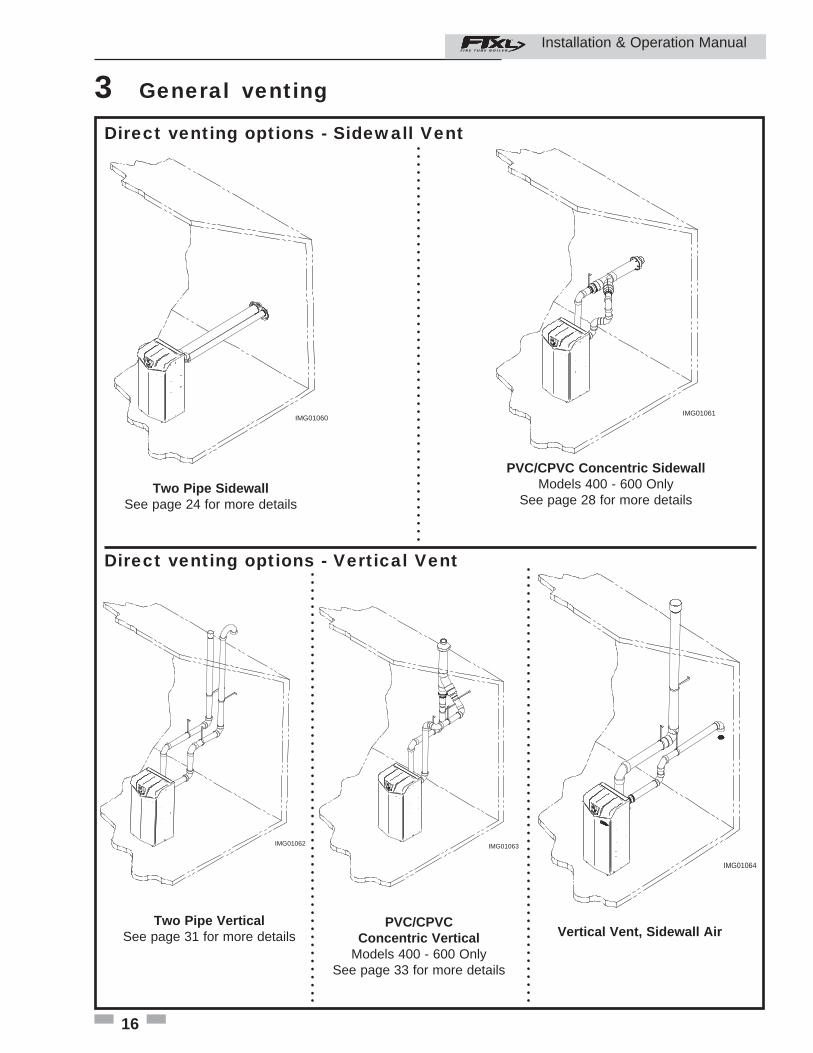
Air intake/vent connections1. Combustion Air Intake Connector (FIG. 3-1) - Used to provide combustion air directly to the unit from outdoors. A fi tting is provided on the unit for fi nal connection. Combustion air piping must be supported per guidelines listed in the National Mechanical Code, Section 305, Table 305.4 or as local codes dictate.
2. Vent Connector (FIG.'s 3-2 thru 3-7) - Used to provide a passageway for conveying combustion gases to the outside. A transition fi tting is provided on the unit for fi nal connection. Vent piping must be supported per the National Building Code, Section 305, Table 305.4 or as local codes dictate.
The FTXL boiler vent and air piping can be installed through the roof or through a sidewall. Follow the procedures in this manual for the method chosen. Refer to the information in this manual to determine acceptable vent and air piping length.
You may use any of the vent/air piping methods covered in this manual. Do not attempt to install the FTXL boiler using any other means.
You must also install air piping from outside to the boiler air intake adapter unless following the Optional Room Air instructions on page 19 of this manual. The resultant installation is direct vent (sealed combustion).
The FTXL is certifi ed as a Category II/IV boiler. All venting systems used with this boiler must be suitable for Category IV operation except for factory approved common vent systems operating as allowed in the Common Venting Section on page 20.
� WARNINGDO NOT mix components from different systems. The vent system could fail, causing leakage of fl ue products into the living space. Mixing of venting materials will void the warranty and certifi cation of the appliance.
� WARNING Do not connect any other appliance to the vent pipe or multiple boilers to a common vent pipe. Failure to comply could result in severe personal injury, death, or substantial property damage.
Improper installation of venting systems may result in injury or death.
� CAUTION
Follow the instructions in Section 1, page 11 of this manual when removing a boiler from an existing vent system.
NOTICE
IMG00986
AIR
Figure 3-1 Near Boiler Air Piping
Installation & Operation Manual
18
3 General venting
Air inlet pipe materials:
The air inlet pipe(s) must be sealed. Choose acceptable combustion air inlet pipe materials from the following list:
PVC, CPVC, Polypropylene or ABS Dryer Vent or Sealed Flexible Duct (not recommended for rooftop air inlet) Galvanized steel vent pipe with joints and seams sealed as specifi ed in this section. Type “B” double-wall vent with joints and seams sealed as specifi ed in this section. AL29-4C, stainless steel material to be sealed to specifi cation of its manufacturer.
*Plastic pipe may require an adapter (not provided) to transition between the air inlet connection on the appliance and the plastic air inlet pipe.
Requirements for installation in Canada1. Installations must be made with a vent pipe system certifi ed to ULC-S636.
2. The fi rst three (3) feet of plastic vent pipe from the appliance fl ue outlet must be readily accessible for visual inspection.
3. The components of the certifi ed vent system must not be interchanged with other vent systems or unlisted pipe/fi ttings. For concentric vent installations, the inner vent tube must be replaced with fi eld supplied certifi ed vent material to comply with this requirement.
4. The 4" Concentric Vent Kit available from Lochinvar (see Section 4 – Sidewall Termination – Optional Concentric Vent) and the 4" Concentric Vent Kit available from IPEX are both approved for use on the FTXL (400 - 600 models only) boiler. Both kits are listed to the ULC-S636 standard for use in Canada.
The appliance output rating will reduce by up to 1.5% for each 25 feet of vent length.
NOTICE
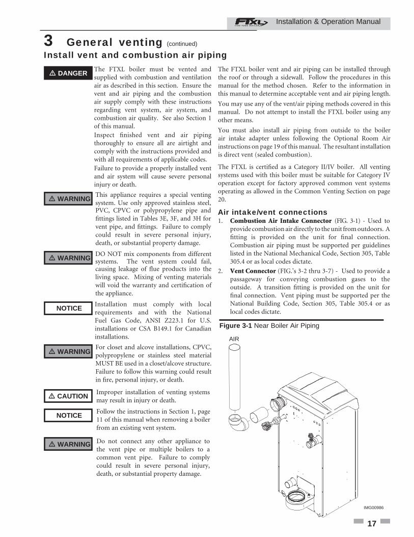
Sizing
Increasing or decreasing combustion air or vent piping sizes is not authorized.
NOTICE
Model Pipe Diameter De-rate per 25 feet of Vent
Air Intake Vent Direct Vent Room Air
400 4" (102 mm) 4" (102 mm) 0.00% 0.00%
500 4" (102 mm) 4" (102 mm) 0.40% 0.40%
600 4" (102 mm) 4" (102 mm) 1.20% 1.20%
725 4" (102 mm) 6" (152 mm) 1.20% 1.20%
850 4" (102 mm) 6" (152 mm) 1.40% 1.40%
The FTXL uses model specifi c combustion air intake and vent piping sizes as detailed in Table 3A below.
Table 3A Air Intake/Vent Piping Sizes
Model Kit NumberEquivalent
Vent Length 400 CVK3007 5' (1.5 m)
500 - 600 CVK3007 30' (9 m)
Table 3B Concentric Vent Kit Equivalent Vent Lengths
Minimum / Maximum allowable combustion air and vent piping lengths are as follows:Combustion Air = 12 equivalent feet (3.7 m) minimum / 100 equivalent feet (30.5 m) maximum
Vent = 12 equivalent feet (3.7 m) minimum / 100 equivalent feet (30.5 m) maximum
When determining equivalent combustion air and vent length, add 5 feet (1.5m) for each 90° elbow and 3 feet (.9 m) for each 45° elbow.
EXAMPLE: 20 feet (6 m) of PVC pipe + (3) 90° elbows + (3) 45° elbows + (1) concentric vent kit (CVK3007) = 49 equivalent feet (15 m) of piping.
� WARNINGUsing air intake materials other than those specifi ed can result in personal injury, death or property damage.
NOTICE The use of double-wall vent or insulated material for the combustion air inlet pipe is recommended in cold climates to prevent the condensation of airborne moisture in the incoming combustion air.
Sealing of Type “B” double-wall vent material or galvanized vent pipe material used for air inlet piping on a sidewall or vertical rooftop Combustion Air Supply System:
a. Seal all joints and seams of the air inlet pipe using either Aluminum Foil Duct Tape meeting UL Standard 723 or 181A-P or a high quality UL Listed silicone sealant such as those manufactured by Dow Corning or General Electric.
b. Do not install seams of vent pipe on the bottom of horizontal runs.
c. Secure all joints with a minimum of three (3) sheet metal screws or pop rivets. Apply Aluminum Foil Duct Tape or silicone sealant to all screws or rivets installed in the vent pipe.
d. Ensure that the air inlet pipes are properly supported.
Installation & Operation Manual
19
3 General venting (continued)
The PVC, CPVC, or ABS air inlet pipe should be cleaned and sealed with the pipe manufacturer’s recommended solvents and standard commercial pipe cement for the material used. The PVC, CPVC, ABS, Dryer Vent or Flex Duct air inlet pipe should use a silicone sealant to ensure a proper seal at the appliance connection and the air inlet cap connection. Dryer vent or fl ex duct should use a screw type clamp to seal the vent to the appliance air inlet and the air inlet cap. Proper sealing of the air inlet pipe ensures that combustion air will be free of contaminants and supplied in proper volume.
Follow the polypropylene manufacturer’s instructions when using polypropylene material as an inlet pipe.
When a sidewall or vertical rooftop combustion air supply system is disconnected for any reason, the air inlet pipe must be resealed to ensure that combustion air will be free of contaminants and supplied in proper volume.
� DANGERFailure to properly seal all joints and seams as required in the air inlet piping may result in fl ue gas recirculation, spillage of fl ue products and carbon monoxide emissions causing severe personal injury or death.
Installation & Operation Manual
Optional room air
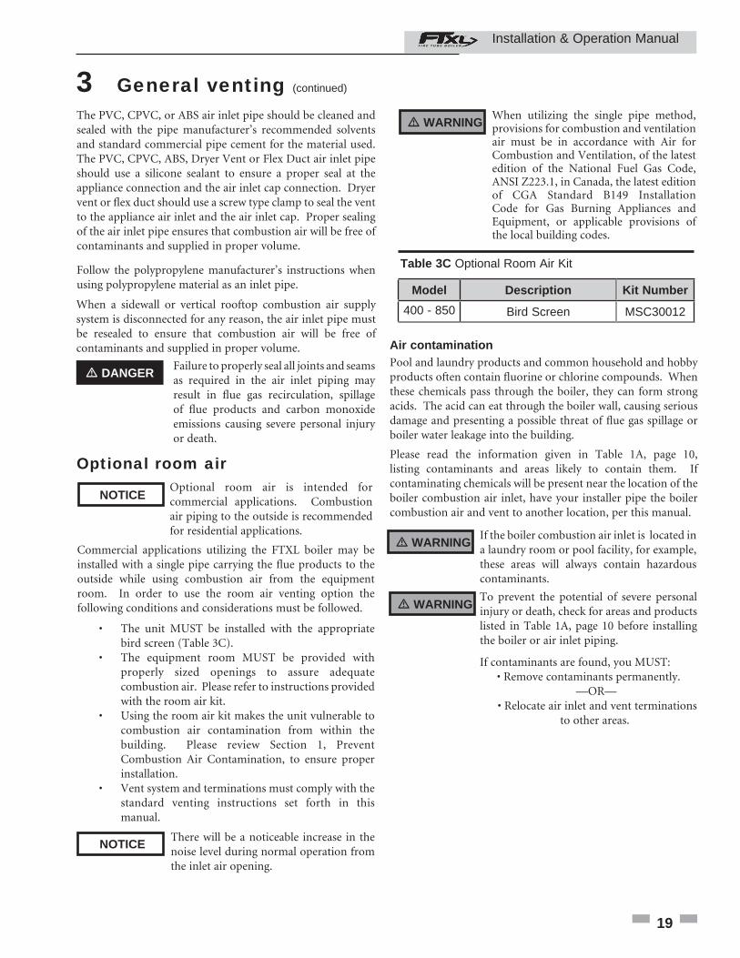
� WARNINGWhen utilizing the single pipe method, provisions for combustion and ventilation air must be in accordance with Air for Combustion and Ventilation, of the latest edition of the National Fuel Gas Code, ANSI Z223.1, in Canada, the latest edition of CGA Standard B149 Installation Code for Gas Burning Appliances and Equipment, or applicable provisions of the local building codes.
Table 3C Optional Room Air Kit
Commercial applications utilizing the FTXL boiler may be installed with a single pipe carrying the fl ue products to the outside while using combustion air from the equipment room. In order to use the room air venting option the following conditions and considerations must be followed.
• The unit MUST be installed with the appropriate bird screen (Table 3C). • The equipment room MUST be provided with properly sized openings to assure adequate combustion air. Please refer to instructions provided with the room air kit. • Using the room air kit makes the unit vulnerable to combustion air contamination from within the building. Please review Section 1, Prevent Combustion Air Contamination, to ensure proper installation. • Vent system and terminations must comply with the standard venting instructions set forth in this manual.
NOTICEOptional room air is intended for commercial applications. Combustion air piping to the outside is recommended for residential applications.
Model Description Kit Number
400 - 850 Bird Screen MSC30012
Air contamination Pool and laundry products and common household and hobby products often contain fl uorine or chlorine compounds. When these chemicals pass through the boiler, they can form strong acids. The acid can eat through the boiler wall, causing serious damage and presenting a possible threat of fl ue gas spillage or boiler water leakage into the building.
Please read the information given in Table 1A, page 10, listing contaminants and areas likely to contain them. If contaminating chemicals will be present near the location of the boiler combustion air inlet, have your installer pipe the boiler combustion air and vent to another location, per this manual.
If the boiler combustion air inlet is located in a laundry room or pool facility, for example, these areas will always contain hazardous contaminants.
To prevent the potential of severe personal injury or death, check for areas and products listed in Table 1A, page 10 before installing the boiler or air inlet piping.
If contaminants are found, you MUST: • Remove contaminants permanently.
—OR— • Relocate air inlet and vent terminations
to other areas.
� WARNING
� WARNING
NOTICEThere will be a noticeable increase in the noise level during normal operation from the inlet air opening.
20
3 General venting
Installing vent and air piping
Use only cleaners, primers, and solvents that are approved for the materials which are joined together.
NOTICE
PVC/CPVC
All PVC vent pipes must be glued, properly supported, and the exhaust must be pitched a minimum of a 1/4 inch per foot back to the boiler (to allow drainage of condensate).
NOTICE
� WARNING The vent connection to the appliance must be made with the starter CPVC pipe section provided with the appliance if PVC/CPVC vent is to be used. The fi eld provided vent fi ttings must be cemented to the CPVC pipe section using an “All Purpose Cement” suitable for PVC and CPVC pipe. Use only the vent materials, primer, and cement specifi ed in Table 3E to make the vent connections. Failure to follow this warning could result in fi re, personal injury, or death.
� WARNINGInsulation should not be used on PVC or CPVC venting materials. The use of insulation will cause increased vent wall temperatures, which could result in vent pipe failure.
This product has been approved for use with the PVC/CPVC vent materials listed in Table 3E on page 21.
Installation & Operation Manual
Common venting
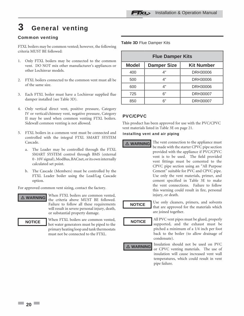
FTXL boilers may be common vented; however, the following criteria MUST BE followed:
1. Only FTXL boilers may be connected to the common vent. DO NOT mix other manufacturer’s appliances or other Lochinvar models.
2. FTXL boilers connected to the common vent must all be of the same size.
3. Each FTXL boiler must have a Lochinvar supplied fl ue damper installed (see Table 3D).
4. Only vertical direct vent, positive pressure, Category IV or vertical/chimney vent, negative pressure, Category II may be used when common venting FTXL boilers. Sidewall common venting is not allowed.
5. FTXL boilers in a common vent must be connected and controlled with the integral FTXL SMART SYSTEM Cascade. a. The Leader may be controlled through the FTXL SMART SYSTEM control through BMS (external 0 - 10V signal), ModBus, BACnet, or its own internally calculated set point.
b. The Cascade (Members) must be controlled by the FTXL Leader boiler using the Lead/Lag Cascade option. For approved common vent sizing, contact the factory.
� WARNINGWhen FTXL boilers are common vented, the criteria above MUST BE followed. Failure to follow all these requirements will result in severe personal injury, death, or substantial property damage.
NOTICEWhen FTXL boilers are common vented, hot water generators must be piped to the primary heating loop and tank thermostats must not be connected to the FTXL.
Table 3D Flue Damper Kits
Flue Damper Kits
Model Damper Size Kit Number400 4" DRH30006
500 4” DRH30006
600 4” DRH30006
725 6” DRH30007
850 6” DRH30007
21
3 General venting (continued)
5. Dry fi t vent or air piping to ensure proper fi t up before assembling any joint. The pipe should go a third to two-thirds into the fi tting to ensure proper sealing after cement is applied.
6. Priming and Cementing: a. Handle fi ttings and pipes carefully to prevent contamination of surfaces. b. Apply a liberal even coat of primer to the fi tting socket and to the pipe end to approximately 1/2" beyond the socket depth. c. Apply a second primer coat to the fi tting socket. d. While primer is still wet, apply an even coat of approved cement to the pipe equal to the depth of the fi tting socket along with an even coat of approved cement to the fi tting socket. e. Apply a second coat of cement to the pipe. f. While the cement is still wet, insert the pipe into the fi tting, if possible twist the pipe a 1/4 turn as you insert it. NOTE: If voids are present, suffi cient cement was not applied and joint could be defective. g. Wipe excess cement from the joint removing ring or beads as it will needlessly soften the pipe.
Table 3E PVC/CPVC Vent Pipe, and Fittings
Approved PVC/CPVC Vent Pipe and FittingsItem Material Standard
Vent pipe
PVC Schedule 40, 80 ANSI/ASTM D1785
PVC - DWV ANSI/ASTM D2665
CPVC Schedule 40, 80 ANSI/ASTM F441
Vent fi ttings
PVC Schedule 40 ANSI/ASTM D2466
PVC Schedule 80 ANSI/ASTM D2467
CPVC Schedule 80 ANSI/ASTM F439
Pipe Cement / Primer
PVC ANSI/ASTM D2564
CPVC ANSI/ASTM F493
NOTICE: DO NOT USE CELLULAR (FOAM) CORE PIPE
NOTE: In Canada, CPVC and PVC vent pipe, fi ttings and cement/primer must be ULC-S636 certifi ed.
1. Work from the boiler to vent or air termination. Do not exceed the lengths given in this manual for the air or vent piping.
2. Cut pipe to the required lengths and deburr the inside and outside of the pipe ends.
3. Chamfer outside of each pipe end to ensure even cement distribution when joining.
4. Clean all pipe ends and fi ttings using a clean dry rag. (Moisture will retard curing and dirt or grease will prevent adhesion.)
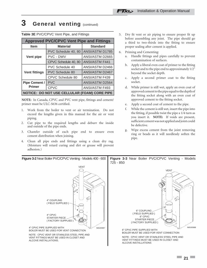
IMG00988
VENT
6" CPVC PIPE SUPPLIED WITHBOILER MUST BE USED FOR VENT CONNECTION
NOTE: CPVC VENT OR STAINLESS STEEL PIPE ANDVENT FITTINGS MUST BE USED IN CLOSET ANDALCOVE INSTALLATIONS
6" COUPLING( FIELD SUPPLIED )
6" CPVCSTARTER PIECE
( FACTORY SUPPLIED )
Figure 3-3 Near Boiler PVC/CPVC Venting - Models 725 - 850
IMG00987
VENT
4" CPVC PIPE SUPPLIED WITHBOILER MUST BE USED FOR VENT CONNECTION
NOTE: CPVC VENT OR STAINLESS STEEL PIPE ANDVENT FITTINGS MUST BE USED IN CLOSET ANDALCOVE INSTALLATIONS.
4" COUPLING( FIELD SUPPLIED )
4" CPVCSTARTER PIECE( FACTORY SUPPLIED )
Figure 3-2 Near Boiler PVC/CPVC Venting - Models 400 - 600
Installation & Operation Manual
22
3 General venting
Model Manufacturer Vent Model Vent Type Adapter Number Joint Connector Sidewall Kit* Retaining Bracket / Adapter*
400-600
CentrothermEco Systems
Innofl ueSingle-Wall
FlexISAAL0404 IANS04 --
IATP0404/ISTAGL0404
DuraVent(M & G)
PolyProSingle-Wall
Flex4PPS-AD 4PPS-LB 4PPS-HLK --
725-800
CentrothermEco Systems
Innofl ueSingle-Wall
FlexISAAL0606 -- --
IATP0606 / ISTAGL0606
DuraVent(M & G)
PolyProSingle-Wall
FlexFSA-6PVCM-
6PPS-- 6PPS-HLK --
* These parts are only needed if the sidewall termination assembly is used (see FIG. 4-5B on page 27).
Table 3G Approved Polypropylene Terminations
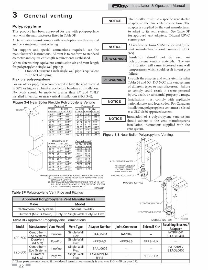
Polypropylene This product has been approved for use with polypropylene vent with the manufacturers listed in Table 3F.
All terminations must comply with listed options in this manual and be a single-wall vent offering.
For support and special connections required, see the manufacturer's instructions. All vent is to conform to standard diameter and equivalent length requirements established.
When determining equivalent combustion air and vent length for polypropylene single-wall piping: • 1 foot of Duravent 4 inch single-wall pipe is equivalent to 1.6 feet of pipingFlexible polypropyleneFor use of fl ex pipe, it is recommended to have the vent material in 32°F or higher ambient space before bending at installation. No bends should be made to greater than 45° and ONLY installed in vertical or near vertical installations (FIG. 3-4).
Use only the adapters and vent system listed in Tables 3F and 3G. DO NOT mix vent systems of different types or manufacturers. Failure to comply could result in severe personal injury, death, or substantial property damage.
� WARNING
Installations must comply with applicable national, state, and local codes. For Canadian installation, polypropylene vent must be listed as a ULC-S636 approved system.
NOTICE
Installation of a polypropylene vent system should adhere to the vent manufacturer’s installation instructions supplied with the vent system.
NOTICE
Approved Polypropylene Vent ManufacturersMake Model
Centrotherm Eco Systems InnoFlue SW/Flex
Duravent (M & G Group) PolyPro Single-Wall / PolyPro Flex
Table 3F Polypropylene Vent Pipe and Fittings
� WARNING Insulation should not be used on polypropylene venting materials. The use of insulation will cause increased vent wall temperatures, which could result in vent pipe failure.
The installer must use a specifi c vent starter adapter at the fl ue collar connection. The adapter is supplied by the vent manufacturer to adapt to its vent system. See Table 3F for approved vent adapters. Discard CPVC starter piece.
NOTICE
All vent connections MUST be secured by the vent manufacturer's joint connector (FIG. 3-5).
NOTICE
IMG00840
*NOTES: 1) FLEX PIPE MAY ONLY BE RUN IN A VERTICAL ORIENTATION 2) ALL VENT LENGTHS REPRESENTED IN ABOVE CHARTS ARE EQUIVALENT LENGTHS. 3) SECTION A IS EQUIVALENT FEET OF RIGID PIPE, WHICH MAY INCLUDE 45 AND 90° ELBOWS. PLEASE SEE SIZING SECTION FOR DETERMINING EQUIVALENT FEET.
“B” DIM3” RIGID 3” FLEX 4” FLEX
Duravent 3”
10 FT20 FT30 FT40 FT50 FT60 FT70 FT80 FT90 FT
60 FT53 FT47 FT40 FT33 FT27 FT20 FT13 FT7 FT
90 FT80 FT70 FT60 FT50 FT40 FT30 FT20 FT10 FT
10 FT20 FT30 FT40 FT50 FT60 FT70 FT80 FT90 FT
30 FT27 FT23 FT20 FT17 FT13 FT10 FT
7 FT3 FT
“A” DIM “B” DIMDuravent 4”
“A” DIM4” RIGID 4” FLEX
“B” DIM3” RIGID 3” FLEX 4” FLEX
Centrotherm 3”
10 FT20 FT30 FT40 FT50 FT60 FT70 FT80 FT90 FT
45 FT40 FT35 FT30 FT25 FT20 FT15 FT10 FT5 FT
90 FT80 FT70 FT60 FT50 FT40 FT30 FT20 FT10 FT
“A” DIM
10 FT20 FT30 FT40 FT50 FT60 FT70 FT80 FT90 FT
33 FT29 FT26 FT22 FT18 FT15 FT11 FT
7 FT4 FT
“B” DIMCentrotherm 4”“A” DIM4” RIGID 4” FLEX
CHIMNEYCAP
A
B
90 FT80 FT70 FT60 FT50 FT40 FT30 FT20 FT10 FT
5” FLEX
Figure 3-4 Near Boiler Flexible Polypropylene Venting
Figure 3-5 Near Boiler Polypropylene Venting
MODELS 400 - 600
MODELS 725 - 850
IMG00990
4” POLYPROPYLENE ADAPTER
4” POLYPROPYLENE JOINT CONNECTOR REQUIRED AT ALL THE COMPONENTS OF THE VENT SYSTEM
4” POLYPROPYLENE ADAPTER
IMG00989
6” POLYPROPYLENE ADAPTER
6” POLYPROPYLENE PIPE
Installation & Operation Manual
23
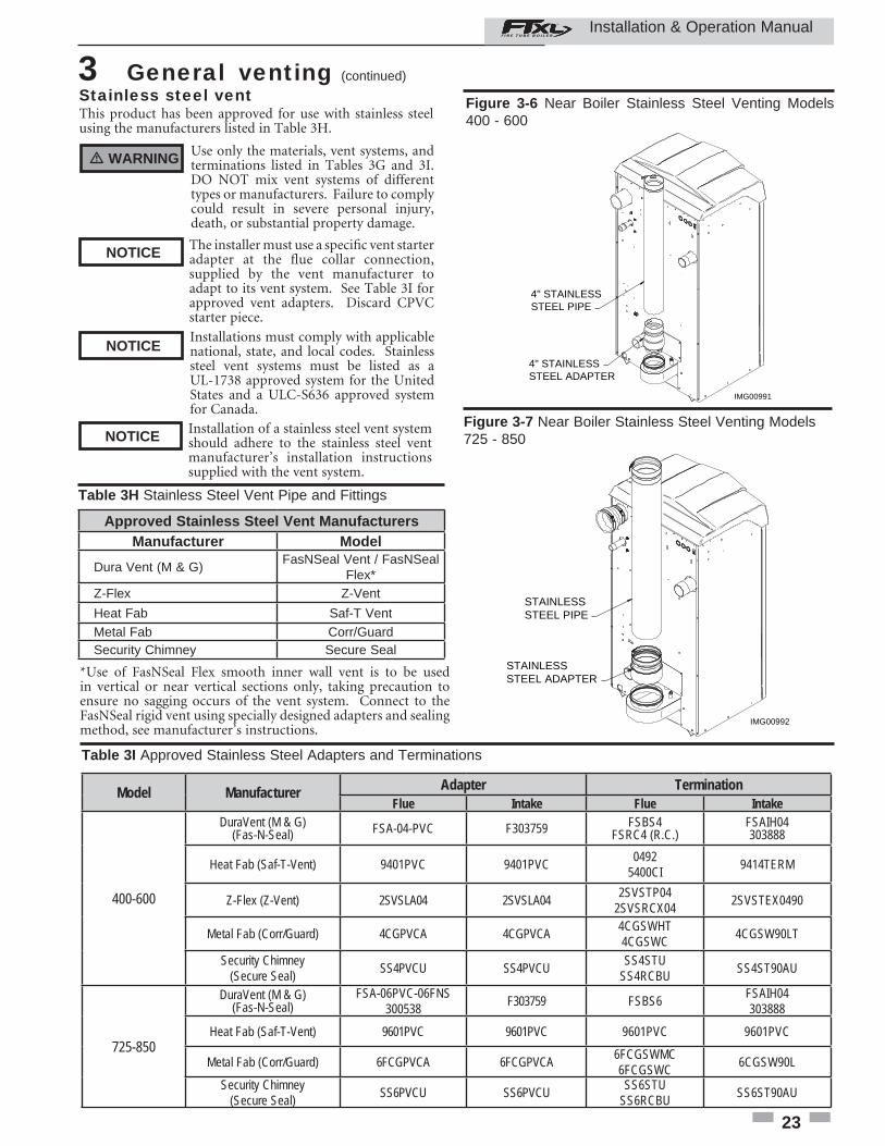
The installer must use a specifi c vent starter adapter at the fl ue collar connection, supplied by the vent manufacturer to adapt to its vent system. See Table 3I for approved vent adapters. Discard CPVC starter piece.
NOTICE
3 General venting (continued)
*Use of FasNSeal Flex smooth inner wall vent is to be used in vertical or near vertical sections only, taking precaution to ensure no sagging occurs of the vent system. Connect to the FasNSeal rigid vent using specially designed adapters and sealing method, see manufacturer’s instructions.
Stainless steel vent This product has been approved for use with stainless steel using the manufacturers listed in Table 3H.
Use only the materials, vent systems, and terminations listed in Tables 3G and 3I. DO NOT mix vent systems of different types or manufacturers. Failure to comply could result in severe personal injury, death, or substantial property damage.
� WARNING
Installations must comply with applicable national, state, and local codes. Stainless steel vent systems must be listed as a UL-1738 approved system for the United States and a ULC-S636 approved system for Canada.
NOTICE
Installation of a stainless steel vent system should adhere to the stainless steel vent manufacturer’s installation instructions supplied with the vent system.
NOTICE
Table 3I Approved Stainless Steel Adapters and Terminations
Model Manufacturer Adapter TerminationFlue Intake Flue Intake
400-600
DuraVent (M & G)(Fas-N-Seal) FSA-04-PVC F303759 FSBS4
FSRC4 (R.C.)FSAIH04303888
Heat Fab (Saf-T-Vent) 9401PVC 9401PVC 04925400CI 9414TERM
Z-Flex (Z-Vent) 2SVSLA04 2SVSLA04 2SVSTP042SVSRCX04 2SVSTEX0490
Metal Fab (Corr/Guard) 4CGPVCA 4CGPVCA 4CGSWHT4CGSWC 4CGSW90LT
Security Chimney (Secure Seal) SS4PVCU SS4PVCU SS4STU
SS4RCBU SS4ST90AU
725-850
DuraVent (M & G)(Fas-N-Seal)
FSA-06PVC-06FNS300538 F303759 FSBS6 FSAIH04
303888
Heat Fab (Saf-T-Vent) 9601PVC 9601PVC 9601PVC 9601PVC
Metal Fab (Corr/Guard) 6FCGPVCA 6FCGPVCA 6FCGSWMC6FCGSWC 6CGSW90L
Security Chimney (Secure Seal) SS6PVCU SS6PVCU SS6STU
SS6RCBU SS6ST90AU
IMG00992
STAINLESS STEEL ADAPTER
STAINLESS STEEL PIPE
Figure 3-7 Near Boiler Stainless Steel Venting Models 725 - 850
IMG00991
4" STAINLESS STEEL ADAPTER
4" STAINLESS STEEL PIPE
Figure 3-6 Near Boiler Stainless Steel Venting Models 400 - 600
Approved Stainless Steel Vent ManufacturersManufacturer Model
Dura Vent (M & G)FasNSeal Vent / FasNSeal
Flex*Z-Flex Z-Vent
Heat Fab Saf-T VentMetal Fab Corr/GuardSecurity Chimney Secure Seal
Table 3H Stainless Steel Vent Pipe and Fittings
Installation & Operation Manual
24
4 Sidewall direct ventingVent/air termination – sidewall
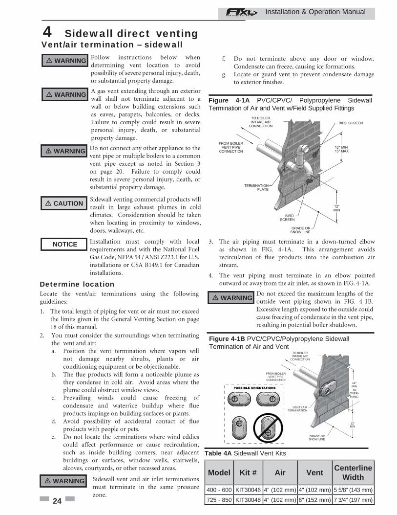
Follow instructions below when determining vent location to avoid possibility of severe personal injury, death, or substantial property damage.
A gas vent extending through an exterior wall shall not terminate adjacent to a wall or below building extensions such as eaves, parapets, balconies, or decks. Failure to comply could result in severe personal injury, death, or substantial property damage.
� WARNING
� WARNING
Determine locationLocate the vent/air terminations using the following guidelines:
1. The total length of piping for vent or air must not exceed the limits given in the General Venting Section on page 18 of this manual.
2. You must consider the surroundings when terminating the vent and air:
a. Position the vent termination where vapors will not damage nearby shrubs, plants or air conditioning equipment or be objectionable.b. The fl ue products will form a noticeable plume as they condense in cold air. Avoid areas where the plume could obstruct window views.c. Prevailing winds could cause freezing of condensate and water/ice buildup where fl ue products impinge on building surfaces or plants.d. Avoid possibility of accidental contact of fl ue products with people or pets.e. Do not locate the terminations where wind eddies could affect performance or cause recirculation, such as inside building corners, near adjacent buildings or surfaces, window wells, stairwells, alcoves, courtyards, or other recessed areas.
� WARNING Sidewall vent and air inlet terminations must terminate in the same pressure zone.
TO BOILERINTAKE AIR
CONNECTION
FROM BOILERVENT PIPE
CONNECTION
VENT / AIRTERMINATION
GRADE ORSNOW LINE
12"MIN
12"MINTO
OVER-HANG
POSSIBLE ORIENTATIONS
Figure 4-1B PVC/CPVC/Polypropylene Sidewall Termination of Air and Vent
Do not exceed the maximum lengths of the outside vent piping shown in FIG. 4-1B. Excessive length exposed to the outside could cause freezing of condensate in the vent pipe, resulting in potential boiler shutdown.
� WARNING
3. The air piping must terminate in a down-turned elbow as shown in FIG. 4-1A. This arrangement avoids recirculation of fl ue products into the combustion air stream.
4. The vent piping must terminate in an elbow pointed outward or away from the air inlet, as shown in FIG. 4-1A.
Figure 4-1A PVC/CPVC/ Polypropylene Sidewall Termination of Air and Vent w/Field Supplied Fittings
Model Kit # Air VentCenterline
Width
400 - 600 KIT30046 4" (102 mm) 4" (102 mm) 5 5/8" (143 mm)
725 - 850 KIT30048 4" (102 mm) 6" (152 mm) 7 3/4" (197 mm)
Table 4A Sidewall Vent Kits
Installation & Operation Manual
Installation must comply with local requirements and with the National Fuel Gas Code, NFPA 54 / ANSI Z223.1 for U.S. installations or CSA B149.1 for Canadian installations.
NOTICE
� WARNING Do not connect any other appliance to the vent pipe or multiple boilers to a common vent pipe except as noted in Section 3 on page 20. Failure to comply could result in severe personal injury, death, or substantial property damage.
� CAUTIONSidewall venting commercial products will result in large exhaust plumes in cold climates. Consideration should be taken when locating in proximity to windows, doors, walkways, etc.
f. Do not terminate above any door or window. Condensate can freeze, causing ice formations.g. Locate or guard vent to prevent condensate damage to exterior fi nishes.
4 Sidewall direct venting (continued)
TO BOILER INTAKEAIR CONNECTION
FROM BOILER VENTPIPE CONNECTION
12" (305 MM) MIN15" (381 MM) MAX
12" (305 MM) MIN
GRADE ORSNOW LINE
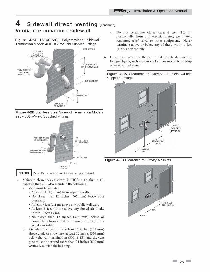
Figure 4-2B Stainless Steel Sidewall Termination Models 725 - 850 w/Field Supplied Fittings
12" (305 MM) MIN 15" (381 MM) MAX
12" (305 MM) MIN
FROM BOILERVENT PIPE
CONNECTION
TO BOILERINTAKE AIR
CONNECTION
BIRD SCREEN
BIRD SCREEN
GRADE ORSNOW LINE
Figure 4-2A PVC/CPVC/ Polypropylene Sidewall Termination Models 400 - 850 w/Field Supplied Fittings
PVC/CPVC or ABS is acceptable air inlet pipe material. NOTICE
Vent/air termination – sidewall
5. Maintain clearances as shown in FIG.’s 4-1A thru 4-4B, pages 24 thru 26. Also maintain the following:
a. Vent must terminate: • At least 6 feet (1.8 m) from adjacent walls.
• No closer than 12 inches (305 mm) below roof overhang. • At least 7 feet (2.1 m) above any public walkway. • At least 3 feet (.9 m) above any forced air intake within 10 feet (3 m). • No closer than 12 inches (305 mm) below or horizontally from any door or window or any other gravity air inlet.b. Air inlet must terminate at least 12 inches (305 mm) above grade or snow line; at least 12 inches (305 mm) below the vent termination (FIG. 4-1B); and the vent pipe must not extend more than 24 inches (610 mm) vertically outside the building.
12” (305 MM)MIN
BIRDSCREEN
(TYPICAL)
12” (305 MM)MIN
12” (305 MM)MIN
Figure 4-3A Clearance to Gravity Air Inlets w/Field Supplied Fittings
25
c. Do not terminate closer than 4 feet (1.2 m) horizontally from any electric meter, gas meter, regulator, relief valve, or other equipment. Never terminate above or below any of these within 4 feet (1.2 m) horizontally.
6. Locate terminations so they are not likely to be damaged by foreign objects, such as stones or balls, or subject to buildup of leaves or sediment.
VENT / AIRTERMINATION
12"MIN.
12"MIN.
12"MIN.
Figure 4-3B Clearance to Gravity Air Inlets
Installation & Operation Manual
26
4 Sidewall direct venting Vent/air termination – sidewall
FORCED AIRINLET
VENT / AIRTERMINATION
7' MIN. ABOVE ANYPUBLIC WALKWAY
IF LESSTHAN 10’
36"MIN.
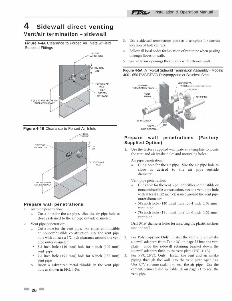
Figure 4-4B Clearance to Forced Air Inlets
Prepare wall penetrations (Factory Supplied Option)1. Use the factory supplied wall plate as a template to locate the vent and air intake holes and mounting holes.
Air pipe penetration:a. Cut a hole for the air pipe. Size the air pipe hole as close as desired to the air pipe outside diameter.
Vent pipe penetration:a. Cut a hole for the vent pipe. For either combustible or noncombustible construction, size the vent pipe hole with at least a 1/2 inch clearance around the vent pipe outer diameter:
• 5½ inch hole (140 mm) hole for 4 inch (102 mm) vent pipe
• 7½ inch hole (191 mm) hole for 6 inch (152 mm) vent pipe
Drill 3/16" diameter holes for inserting the plastic anchors into the wall.
2. For Polypropylene Only: Install the vent and air intake sidewall adapters from Table 3G on page 22 into the vent plate. Slide the sidewall retaining bracket down the sidewall adapters fl ush to the vent plate (FIG. 4-4A).3. For PVC/CPVC Only: Install the vent and air intake piping through the wall into the vent plate openings. Use RTV silicone sealant to seal the air pipe. Use the cement/primer listed in Table 3E on page 21 to seal the vent pipe.
3. Use a sidewall termination plate as a template for correct location of hole centers.
4. Follow all local codes for isolation of vent pipe when passing through fl oors or walls.
5. Seal exterior openings thoroughly with exterior caulk.
SIDEWALLTERMINATION PLATE
VENTPIPING
GALVANIZEDTHIMBLE (WHEN REQUIRED BY LOCAL CODES)
ELBOW
ELBOW
AIR PIPING
BIRD SCREEN
BIRD SCREEN
Figure 4-5A A Typical Sidewall Termination Assembly - Models 400 - 850 PVC/CPVC/ Polypropylene or Stainless Steel
Prepare wall penetrations 1. Air pipe penetration:
a. Cut a hole for the air pipe. Size the air pipe hole as close as desired to the air pipe outside diameter.
2. Vent pipe penetration:a. Cut a hole for the vent pipe. For either combustible or noncombustible construction, size the vent pipe hole with at least a 1/2 inch clearance around the vent pipe outer diameter: • 5½ inch hole (140 mm) hole for 4 inch (102 mm) vent pipe • 7½ inch hole (191 mm) hole for 6 inch (152 mm) vent pipeb. Insert a galvanized metal thimble in the vent pipe hole as shown in FIG. 4-5A.
36” (914 MM)MIN
7’ (2.1 M) MIN ABOVE ANYPUBLIC WALKWAY
IF LESSTHAN 10’ (3 M)
FORCED AIRINLET
BIRDSCREEN
(TYPICAL)
Figure 4-4A Clearance to Forced Air Inlets w/Field Supplied Fittings
Installation & Operation Manual
27
4 Sidewall direct venting (continued)
All vent pipes and air inlets must terminate at the same height to avoid possibility of severe personal injury, death, or substantial property damage.
Multiple vent/air terminations
1. When terminating multiple FTXL’s terminate each vent/air connection as described in this manual(FIG. 4-6A).
2. Place wall penetrations to obtain minimum clearance of 12 inches (305 mm) between vent pipe and adjacent air inlet elbow, as shown in FIG. 4-6B for U.S. installations. For Canadian installations, provide clearances required by CSA B149.1 Installation Code.
3. The air inlet of a FTXL is part of a direct vent connection. It is not classifi ed as a forced air intake with regard to spacing from adjacent boiler vents.
VENT
12” (305 MM) MIN15” (381 MM) MAX
12” (305 MM) MIN. BETWEEN EDGE OF AIR PIPE AND ADJACENT VENTPIPE
AIR
Figure 4-6A Multiple Vent Terminations w/Field Supplied Fittings (must also comply with Figure 4-1A)
� WARNING
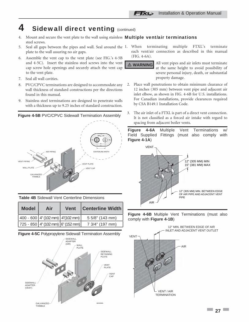
4. Mount and secure the vent plate to the wall using stainless steel screws. 5. Seal all gaps between the pipes and wall. Seal around the plate to the wall assuring no air gaps.
6. Assemble the vent cap to the vent plate (see FIG.’s 4-5B and 4-5C). Insert the stainless steel screws into the vent cap screw hole openings and securely attach the vent cap to the vent plate.
7. Seal all wall cavities.
8. PVC/CPVC terminations are designed to accommodate any wall thickness of standard constructions per the directions found in this manual.
9. Stainless steel terminations are designed to penetrate walls with a thickness up to 9.25 inches of standard construction.
Figure 4-5B PVC/CPVC Sidewall Termination Assembly
VENT PIPING
GALVANIZEDTHIMBLE
VENT CAP
AIR PIPING
WALL PLATE
VENT PLATE
VENT AIR
CENTERLINE WIDTH
Model Air Vent Centerline Width
400 - 600 4" (102 mm) 4"(102 mm) 5 5/8" (143 mm)
725 - 850 4" (102 mm) 6" (152 mm) 7 3/4" (197 mm)
Table 4B Sidewall Vent Centerline Dimensions
SIDEWALLADAPTER(AIR)
SIDEWALLADAPTER(VENT)
WALLPLATE
GALVANIZEDTHIMBLE
SIDEWALLRETAININGPLATE
VENTPLATE
VENTCAP
IMG00085
Figure 4-5C Polypropylene Sidewall Termination Assembly
12" MIN. BETWEEN EDGE OF AIR INLET AND ADJACENT VENT OUTLET
VENT / AIRTERMINATION
VENT
AIR
Figure 4-6B Multiple Vent Terminations (must also comply with Figure 4-1B)
Installation & Operation Manual
28
4 Sidewall direct venting
4" (102 MM) DIA.
6" (152 MM) DIA.
RAIN CAP
"Y" CONCENTRICFITTING
"FLEXIBLE" PIPECOUPLING
6" (152 MM) DIA.
6" (152 MM) DIA.
6" (152 MM) TO 4" (102 MM) REDUCER
Figure 4-8 Kit Contents_CVK3007 - Models 400 - 600
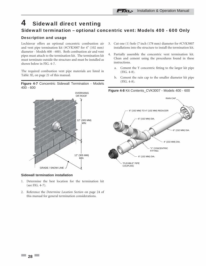
Sidewall termination installation
1. Determine the best location for the termination kit (see FIG. 4-7).
2. Reference the Determine Location Section on page 24 of this manual for general termination considerations.
3. Cut one (1) hole (7 inch (178 mm) diameter for #CVK3007 installations into the structure to install the termination kit.
4. Partially assemble the concentric vent termination kit. Clean and cement using the procedures found in these instructions.
a. Cement the Y concentric fi tting to the larger kit pipe (FIG. 4-8).
b. Cement the rain cap to the smaller diameter kit pipe (FIG. 4-8).
Sidewall termination – optional concentric vent: Models 400 - 600 OnlyDescription and usageLochinvar offers an optional concentric combustion air and vent pipe termination kit (#CVK3007 for 4" (102 mm) diameter - Models 400 - 600). Both combustion air and vent pipes must attach to the termination kit. The termination kit must terminate outside the structure and must be installed as shown below in FIG. 4-7.
The required combustion vent pipe materials are listed in Table 3E, on page 21 of this manual.
OVERHANG OR ROOF
12" (305 MM)MIN
12" (305 MM)MIN
GRADE / SNOW LINE
Figure 4-7 Concentric Sidewall Termination - Models 400 - 600
Installation & Operation Manual
29
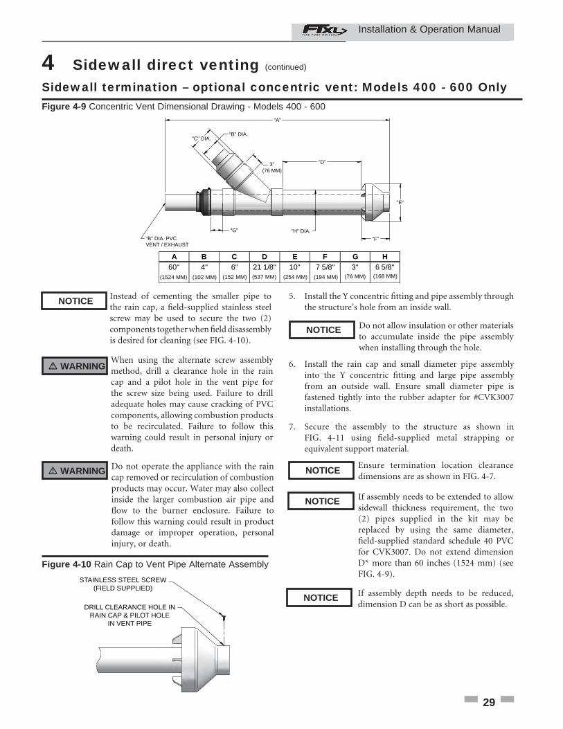
4 Sidewall direct venting (continued) Sidewall termination – optional concentric vent: Models 400 - 600 OnlyFigure 4-9 Concentric Vent Dimensional Drawing - Models 400 - 600
Instead of cementing the smaller pipe to the rain cap, a fi eld-supplied stainless steel screw may be used to secure the two (2) components together when fi eld disassembly is desired for cleaning (see FIG. 4-10).
When using the alternate screw assembly method, drill a clearance hole in the rain cap and a pilot hole in the vent pipe for the screw size being used. Failure to drill adequate holes may cause cracking of PVC components, allowing combustion products to be recirculated. Failure to follow this warning could result in personal injury or death.
Do not operate the appliance with the rain cap removed or recirculation of combustion products may occur. Water may also collect inside the larger combustion air pipe and fl ow to the burner enclosure. Failure to follow this warning could result in product damage or improper operation, personal injury, or death.
STAINLESS STEEL SCREW(FIELD SUPPLIED)
DRILL CLEARANCE HOLE INRAIN CAP & PILOT HOLE
IN VENT PIPE
Figure 4-10 Rain Cap to Vent Pipe Alternate Assembly
5. Install the Y concentric fi tting and pipe assembly through the structure’s hole from an inside wall.
Do not allow insulation or other materials to accumulate inside the pipe assembly when installing through the hole.
6. Install the rain cap and small diameter pipe assembly into the Y concentric fi tting and large pipe assembly from an outside wall. Ensure small diameter pipe is fastened tightly into the rubber adapter for #CVK3007 installations.
7. Secure the assembly to the structure as shown in FIG. 4-11 using fi eld-supplied metal strapping or equivalent support material.
Ensure termination location clearance dimensions are as shown in FIG. 4-7.
If assembly needs to be extended to allow sidewall thickness requirement, the two (2) pipes supplied in the kit may be replaced by using the same diameter, fi eld-supplied standard schedule 40 PVC for CVK3007. Do not extend dimension D* more than 60 inches (1524 mm) (see FIG. 4-9).
NOTICE
� WARNING
� WARNING
NOTICE
NOTICE
NOTICE
If assembly depth needs to be reduced, dimension D can be as short as possible.
NOTICE
"B" DIA. PVCVENT / EXHAUST
"A"
"H" DIA.
"D"
"E"
"F"
"G"
3"(76 MM)
A B C D E F G H60" 4" 6" 21 1/8" 10" 7 5/8" 3" 6 5/8"
"C" DIA."B" DIA.
(1524 MM) (102 MM) (152 MM) (537 MM) (254 MM) (194 MM) (76 MM) (168 MM)
Installation & Operation Manual
30
4 Sidewall direct venting Sidewall termination – optional concentric vent: Models 400 - 600 Only
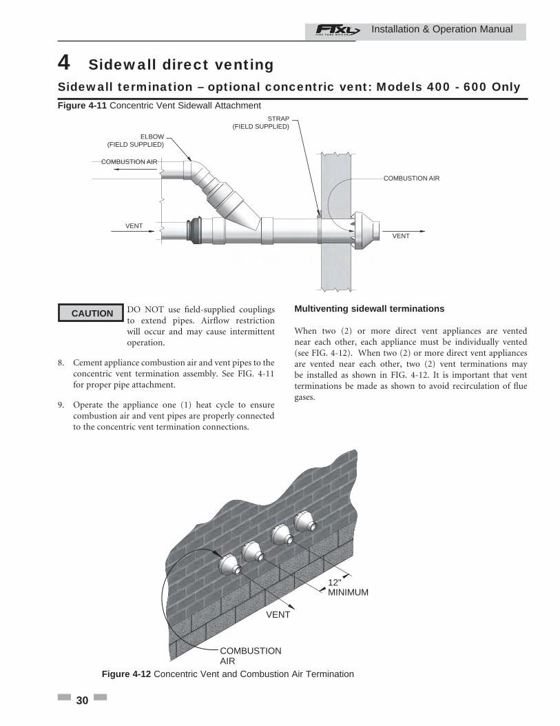
Multiventing sidewall terminations
When two (2) or more direct vent appliances are vented near each other, each appliance must be individually vented (see FIG. 4-12). When two (2) or more direct vent appliances are vented near each other, two (2) vent terminations may be installed as shown in FIG. 4-12. It is important that vent terminations be made as shown to avoid recirculation of fl ue gases.
VENT
COMBUSTIONAIR
12"MINIMUM
Figure 4-12 Concentric Vent and Combustion Air Termination
COMBUSTION AIR
VENT
VENT
COMBUSTION AIR
STRAP(FIELD SUPPLIED)
ELBOW(FIELD SUPPLIED)
Figure 4-11 Concentric Vent Sidewall Attachment
DO NOT use fi eld-supplied couplings to extend pipes. Airfl ow restriction will occur and may cause intermittent operation.
8. Cement appliance combustion air and vent pipes to the concentric vent termination assembly. See FIG. 4-11 for proper pipe attachment.
9. Operate the appliance one (1) heat cycle to ensure combustion air and vent pipes are properly connected to the concentric vent termination connections.
CAUTION
Installation & Operation Manual
31
5 Vertical direct ventingVent/air termination – vertical
Follow instructions below when determining vent location to avoid possibility of severe personal injury, death or substantial property damage.
Determine locationLocate the vent/air terminations using the following guidelines:
1. The total length of piping for vent or air must not exceed the limits given in the General Venting Section on page 18 of this manual.
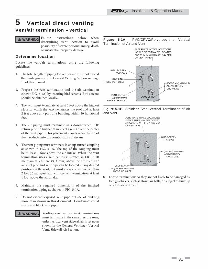
2. Prepare the vent termination and the air termination elbow (FIG. 5-1A) by inserting bird screens. Bird screens should be obtained locally.
3. The vent must terminate at least 3 feet above the highest place in which the vent penetrates the roof and at least 2 feet above any part of a building within 10 horizontal feet.
4. The air piping must terminate in a down-turned 180° return pipe no further than 2 feet (.6 m) from the center of the vent pipe. This placement avoids recirculation of fl ue products into the combustion air stream.
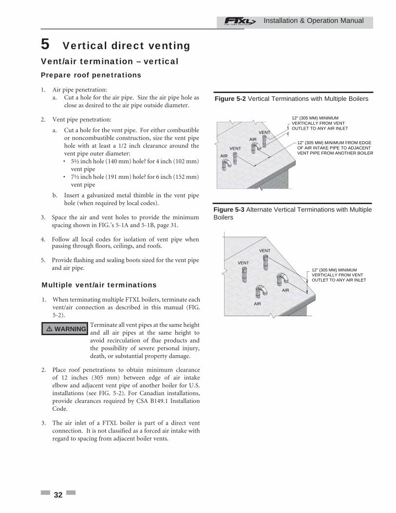
5. The vent piping must terminate in an up-turned coupling as shown in FIG. 5-1A. The top of the coupling must be at least 1 foot above the air intake. When the vent termination uses a rain cap as illustrated in FIG. 5-1B maintain at least 36" (914 mm) above the air inlet. The air inlet pipe and vent pipe can be located in any desired position on the roof, but must always be no further than 2 feet (.6 m) apart and with the vent termination at least 1 foot above the air intake.
6. Maintain the required dimensions of the fi nished termination piping as shown in FIG. 5-1A.
7. Do not extend exposed vent pipe outside of building more than shown in this document. Condensate could freeze and block vent pipe.
ALTERNATE INTAKE LOCATIONS:INTAKE PIPES MAY BE LOCATED ANYWHERE WITHIN 24" (610 MM) OF VENT PIPE
BIRD SCREEN (TYPICAL)
COUPLING(FIELD SUPPLIED)
VENT OUTLET 12" MINIMUMABOVE AIR INLET
6" (152 MM) MINIMUMABOVE ROOF /SNOW LINE
VENT
COMBUSTION AIR
Figure 5-1A PVC/CPVC/Polypropylene Vertical Termination of Air and Vent
8. Locate terminations so they are not likely to be damaged by foreign objects, such as stones or balls, or subject to buildup of leaves or sediment.
� WARNING
� WARNING Rooftop vent and air inlet terminations must terminate in the same pressure zone, unless vertical vent sidewall air is set up as shown in the General Venting - Vertical Vent, Sidewall Air Section.
6" (152 MM) MINIMUMABOVE ROOF /
SNOW LINE
VENT
COM,BUSTION AIR
ALTERNATE INTAKE LOCATIONS:INTAKE PIPES MAY BE LOCATEDANYWHERE WITHIN 24” (610 MM) OF VENT PIPE
VENT OUTLET36” (914 MM) MINIMUM
ABOVE AIR INLET
BIRD SCREEN(TYPICAL)
Figure 5-1B Stainless Steel Vertical Termination of Air and Vent
Installation & Operation Manual
32
5 Vertical direct venting Vent/air termination – vertical Prepare roof penetrations
1. Air pipe penetration:a. Cut a hole for the air pipe. Size the air pipe hole as close as desired to the air pipe outside diameter.
2. Vent pipe penetration:
a. Cut a hole for the vent pipe. For either combustible or noncombustible construction, size the vent pipe hole with at least a 1/2 inch clearance around the vent pipe outer diameter:
• 5½ inch hole (140 mm) hole? for 4 inch (102 mm) vent pipe • 7½ inch hole (191 mm) hole? for 6 inch (152 mm) vent pipe
b. Insert a galvanized metal thimble in the vent pipe hole (when required by local codes).
3. Space the air and vent holes to provide the minimum spacing shown in FIG.’s 5-1A and 5-1B, page 31.
4. Follow all local codes for isolation of vent pipe when passing through fl oors, ceilings, and roofs.
5. Provide fl ashing and sealing boots sized for the vent pipe and air pipe.
Multiple vent/air terminations
1. When terminating multiple FTXL boilers, terminate each vent/air connection as described in this manual (FIG. 5-2).
Terminate all vent pipes at the same height and all air pipes at the same height to avoid recirculation of fl ue products and the possibility of severe personal injury, death, or substantial property damage.
2. Place roof penetrations to obtain minimum clearance of 12 inches (305 mm) between edge of air intake elbow and adjacent vent pipe of another boiler for U.S. installations (see FIG. 5-2). For Canadian installations, provide clearances required by CSA B149.1 Installation Code.
3. The air inlet of a FTXL boiler is part of a direct vent connection. It is not classifi ed as a forced air intake with regard to spacing from adjacent boiler vents.
12" (305 MM) MINIMUM VERTICALLY FROM VENT OUTLET TO ANY AIR INLET
12" (305 MM) MINIMUM FROM EDGE OF AIR INTAKE PIPE TO ADJACENT VENT PIPE FROM ANOTHER BOILER
AIR
AIR
VENT
VENT
Figure 5-2 Vertical Terminations with Multiple Boilers
VENT
VENT
AIR
AIR
12" (305 MM) MINIMUM VERTICALLY FROM VENT OUTLET TO ANY AIR INLET
Figure 5-3 Alternate Vertical Terminations with Multiple Boilers
� WARNING
Installation & Operation Manual
33
5 Vertical direct venting (continued) Vertical termination – optional concentric vent: Models 400 - 600 Only Description and usage
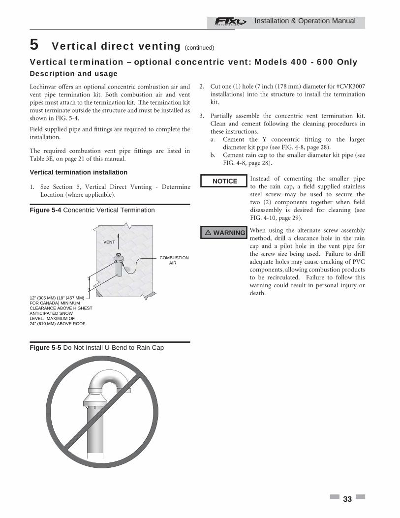
Lochinvar offers an optional concentric combustion air and vent pipe termination kit. Both combustion air and vent pipes must attach to the termination kit. The termination kit must terminate outside the structure and must be installed as shown in FIG. 5-4.
Field supplied pipe and fi ttings are required to complete the installation.
The required combustion vent pipe fi ttings are listed in Table 3E, on page 21 of this manual.
Vertical termination installation
1. See Section 5, Vertical Direct Venting - Determine Location (where applicable).
Instead of cementing the smaller pipe to the rain cap, a fi eld supplied stainless steel screw may be used to secure the two (2) components together when fi eld disassembly is desired for cleaning (see FIG. 4-10, page 29).
When using the alternate screw assembly method, drill a clearance hole in the rain cap and a pilot hole in the vent pipe for the screw size being used. Failure to drill adequate holes may cause cracking of PVC components, allowing combustion products to be recirculated. Failure to follow this warning could result in personal injury or death.
2. Cut one (1) hole (7 inch (178 mm) diameter for #CVK3007 installations) into the structure to install the termination kit.
3. Partially assemble the concentric vent termination kit. Clean and cement following the cleaning procedures in these instructions.
a. Cement the Y concentric fi tting to the larger diameter kit pipe (see FIG. 4-8, page 28).
b. Cement rain cap to the smaller diameter kit pipe (see FIG. 4-8, page 28).
VENT
COMBUSTION AIR
12" (305 MM) (18" (457 MM) FOR CANADA) MINIMUM CLEARANCE ABOVE HIGHESTANTICIPATED SNOWLEVEL. MAXIMUM OF24" (610 MM) ABOVE ROOF.
Figure 5-4 Concentric Vertical Termination
NOTICE
� WARNING
Figure 5-5 Do Not Install U-Bend to Rain Cap
Installation & Operation Manual
34
5 Vertical direct venting Vertical termination – optional concentric vent: Models 400 - 600 Only
ELBOW(FIELD SUPPLIED)
SUPPORT(FIELD SUPPLIED)
ROOF BOOT /FLASHING(FIELD SUPPLIED)
VENT
COMBUSTIONAIR
VENT
12" (305 MM) (18" (457 MM) FOR CANADA)MINIMUM CLEARANCE ABOVE HIGHESTANTICIPATED SNOW LEVEL. MAXIMUM OF24” (610 MM) ABOVE ROOF.
COMBUSTIONAIR
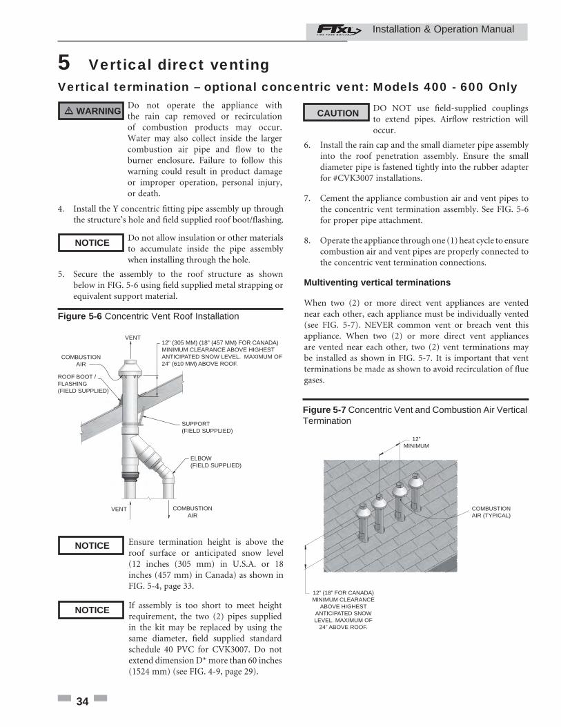
Figure 5-6 Concentric Vent Roof Installation
Ensure termination height is above the roof surface or anticipated snow level (12 inches (305 mm) in U.S.A. or 18 inches (457 mm) in Canada) as shown in FIG. 5-4, page 33.
If assembly is too short to meet height requirement, the two (2) pipes supplied in the kit may be replaced by using the same diameter, fi eld supplied standard schedule 40 PVC for CVK3007. Do not extend dimension D* more than 60 inches (1524 mm) (see FIG. 4-9, page 29).
CAUTION DO NOT use fi eld-supplied couplings to extend pipes. Airfl ow restriction will occur.
6. Install the rain cap and the small diameter pipe assembly into the roof penetration assembly. Ensure the small diameter pipe is fastened tightly into the rubber adapter for #CVK3007 installations.
7. Cement the appliance combustion air and vent pipes to the concentric vent termination assembly. See FIG. 5-6 for proper pipe attachment.
8. Operate the appliance through one (1) heat cycle to ensure combustion air and vent pipes are properly connected to the concentric vent termination connections.
Multiventing vertical terminations
When two (2) or more direct vent appliances are vented near each other, each appliance must be individually vented (see FIG. 5-7). NEVER common vent or breach vent this appliance. When two (2) or more direct vent appliances are vented near each other, two (2) vent terminations may be installed as shown in FIG. 5-7. It is important that vent terminations be made as shown to avoid recirculation of fl ue gases.
12”MINIMUM
12” (18” FOR CANADA)MINIMUM CLEARANCE
ABOVE HIGHESTANTICIPATED SNOWLEVEL. MAXIMUM OF
24” ABOVE ROOF.
COMBUSTIONAIR (TYPICAL)
Figure 5-7 Concentric Vent and Combustion Air Vertical Termination
Do not operate the appliance with the rain cap removed or recirculation of combustion products may occur. Water may also collect inside the larger combustion air pipe and fl ow to the burner enclosure. Failure to follow this warning could result in product damage or improper operation, personal injury, or death.
4. Install the Y concentric fi tting pipe assembly up through the structure’s hole and fi eld supplied roof boot/fl ashing.
Do not allow insulation or other materials to accumulate inside the pipe assembly when installing through the hole.
5. Secure the assembly to the roof structure as shown below in FIG. 5-6 using fi eld supplied metal strapping or equivalent support material.
� WARNING
NOTICE
NOTICE
NOTICE
Installation & Operation Manual
35
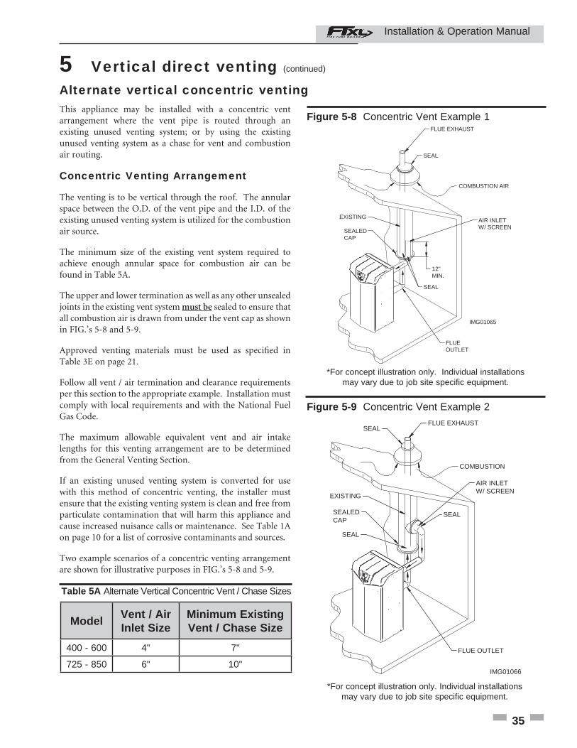
5 Vertical direct venting (continued) Alternate vertical concentric ventingThis appliance may be installed with a concentric vent arrangement where the vent pipe is routed through an existing unused venting system; or by using the existing unused venting system as a chase for vent and combustion air routing.
Concentric Venting Arrangement
The venting is to be vertical through the roof. The annular space between the O.D. of the vent pipe and the I.D. of the existing unused venting system is utilized for the combustion air source.
The minimum size of the existing vent system required to achieve enough annular space for combustion air can be found in Table 5A.
The upper and lower termination as well as any other unsealed joints in the existing vent system must be sealed to ensure that all combustion air is drawn from under the vent cap as shown in FIG.’s 5-8 and 5-9.
Approved venting materials must be used as specifi ed in Table 3E on page 21.
Follow all vent / air termination and clearance requirements per this section to the appropriate example. Installation must comply with local requirements and with the National Fuel Gas Code.
The maximum allowable equivalent vent and air intake lengths for this venting arrangement are to be determined from the General Venting Section.
If an existing unused venting system is converted for use with this method of concentric venting, the installer must ensure that the existing venting system is clean and free from particulate contamination that will harm this appliance and cause increased nuisance calls or maintenance. See Table 1A on page 10 for a list of corrosive contaminants and sources.
Two example scenarios of a concentric venting arrangement are shown for illustrative purposes in FIG.’s 5-8 and 5-9.
Figure 5-8 Concentric Vent Example 1
IMG01065
FLUE EXHAUST
SEAL
COMBUSTION AIR
AIR INLETW/ SCREEN
12"MIN.
SEALEDCAP
SEAL
FLUEOUTLET
EXISTING
*For concept illustration only. Individual installationsmay vary due to job site specifi c equipment.
Figure 5-9 Concentric Vent Example 2
IMG01066
FLUE EXHAUSTSEAL
SEAL
AIR INLETW/ SCREEN
EXISTING
FLUE OUTLET
SEALEDCAP
SEAL
COMBUSTION
*For concept illustration only. Individual installationsmay vary due to job site specifi c equipment.
ModelVent / Air Inlet Size
Minimum Existing Vent / Chase Size
400 - 600 4" 7"
725 - 850 6" 10"
Table 5A Alternate Vertical Concentric Vent / Chase Sizes
Installation & Operation Manual
36
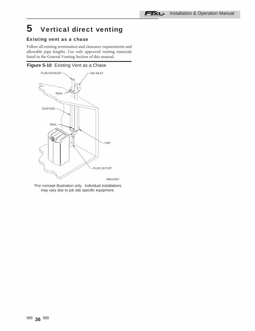
5 Vertical direct venting Existing vent as a chaseFollow all existing termination and clearance requirements and allowable pipe lengths. Use only approved venting materials listed in the General Venting Section of this manual.
Figure 5-10 Existing Vent as a Chase
IMG01067
FLUE EXHAUST AIR INLET
SEAL
EXISTING
CAP
SEAL
FLUE OUTLET
*For concept illustration only. Individual installationsmay vary due to job site specifi c equipment.
Installation & Operation Manual