Operator’s Manual Environmental Surveillance over the Internet

MHP
For technical assistance or the dealer nearest you, consult our web page at www.landa.com
8.913-925.0
OPERATOR’S MANUAL
LISTED ®
89139250-7
MHP4-3000 MHP4-3500

CONTENTS
2
Model Number ______________________________
Serial Number ______________________________
Date of Purchase ____________________________
The model and serial numbers will be found on a decal attached
to the pressure washer. You should record both serial number and
date of purchase and keep in a safe place for future reference.
LANDA MHP • 8.913-925.0 • Rev. 5/12
Introduction & Important Safety Information 4-5
Component Identification 6
Assembly Instructions 7
Operating Instructions 8
Detergents & General Washing Techniques 9
Shutdown & Cleanup 10
Troubleshooting 11-14
Preventative Maintenance 15-17
Maintenance Schedule & Oil Change Record 18
Exploded View, Control Panel and Parts List 19
Exploded View, Left Side, All Models 20
Exploded View, Right Side, All Models 21
Exploded View Parts List, All Models 22-23
Exploded View, Detergent/Float Combination 24
Detergent/Float Combination Parts List 25
Hose and Spray Gun Assembly 26
Downstream Injector Assembly 27
Pump Specifications 28-29
Landa Sure Fire Burner Replacement Parts 30-31
LT.1 Pump Exploded View and Parts List 32-33
VRT 3 Unloader Exploded View and Parts List 34
Warranty

LANDA MHP • 8.913-925.0 • Rev. 5/12
3
PR
ES
SU
RE
WA
SH
ER
OP
ER
ATO
R’S
MA
NU
AL
INTRODUCTION & IMPORTANT SAFETY INFORMATION
Thank you for purchasing this Pressure Washer.
We reserve the right to make changes at any time without incurring any obligation.
Owner/User Responsibility:The owner and/or user must have an understanding of the manufacturer’s operating instructions and warnings before using this pressure washer. Warning information should be emphasized and understood. If the operator is not fluent in English, the manufacturer’s instructions and warnings shall be read to and discussed with the operator in the operator’s native language by the purchaser/owner, making sure that the operator com-prehends its contents.
Owner and/or user must study and maintain for future reference the manufacturers’ instructions.
The operator must know how to stop the machine quickly and understand the operation of all controls. Never permit anyone to operate the engine without proper instructions.
This manual should be considered a permanent part of the machine and should remain with it if machine is resold.
When ordering parts, please specify model and serial number. Use only identical replacement parts.
This machine is to be used only by trained op-erators.
IMPORTANT SAFETY INFORMATION
READ OPERATOR’S MANUAL THOROUGHLY
PRIOR TO USE.
WARNING: To reduce the risk of injury, read operating instruc-tions carefully before using.
1. Read the owner's manual thoroughly. Failure to fol-low instructions could cause malfunction of the machine and result in death, serious bodily injury and/or property damage.
2. Know how to stop the machine and bleed pressure quickly. Be thoroughly familiar with the controls.
3. Stay alert — watch what you are doing.
WARNING
KEEP WATER SPRAY AWAY FROM
ELECTRICAL WIRING.
WARNING: Keep wand, hose, and water spray away from electric wiring or fatal electric shock may result.
4. All installations must comply with local codes. Contact your electrician, plumber, utility company or the selling distributor for specific details.
WARNING
EAR PROTECTION MUST BE WORN
WARNING: This machine exceeds 85 db appropriate ear protection must be worn.
WARNING
USE PROTECTIVE EYE WEAR
AND CLOTHING WHEN OPERATING THIS EQUIPMENT.
WARNING: High pressure spray can cause paint chips or other particles to become airborne and fly at high speeds. To avoid personal injury, eye, hand and foot safety devices must be worn.
5. Eye, hand, and foot protection must be worn when using this equipment.
6. Keep operating area clear of all persons.
RISK OF EXPLOSION: OPERATE ONLY WHERE OPEN FLAME OR TORCH
IS PERMITTED
WARNING WARNING: Flammable liquids can create fumes which can ig-nite, causing property damage or severe injury.
WARNING: Risk of explosion — Operate only where open flame or torch is permitted.
RISK OF FIRE. DO NOT ADD FUEL WHEN OPERATING
MACHINE.
WARNING WARNING: Risk of fire — Do not add fuel when the product is operating or still hot.
WARNING: Do not use gasoline crankcase draining or oil con-taining gasoline, solvents or alcohol. Doing so will result in fire and/or explosion.
WARNING: Risk of fire — Do not Spray flammable liquids.
7. Allow engine to cool for 1-2 minutes before refu-eling. If any fuel is spilled, make sure the area is dry before testing the spark plug or starting the engine. (Fire and/or explosion may occur if this is not done.)
Gasoline engines on mobile or portable equipment shall be refueled:
a. outdoors;
b. with the engine on the equipment stopped;
c. with no source of ignition within 10 feet of the dispensing point; and
d. with an allowance made for expansion of the fuel should the equipment be exposed to a higher ambient temperature.

LANDA MHP • 8.913-925.0 • Rev. 5/12
OP
ER
ATO
R’S
MA
NU
AL
PR
ES
SU
RE
WA
SH
ER
4
15. Be certain all quick coupler fittings are secured before using pressure washer.
RISK OF INJECTION OR SEVERE INJURY TO PERSONS. KEEP CLEAR OF NOZZLE.
WARNING WARNING: High pressure devel-oped by these machines will cause personal injury or equip-ment damage. Keep clear of nozzle. Use caution when oper-ating. Do not direct discharge stream at people, or severe in-jury or death will result.
WARNING
PROTECT FROM FREEZING
WARNING: Protect machine from freezing.
16. To keep machine in best operating conditions, it is important you protect machine from freezing. Failure to protect mach ine f rom f reez ing could cause malfunction of the machine and result in death,
serious bodily injury, and/or property damage. Fol-low storage instructions specified in this manual.
17. Inlet water must be clean fresh water and no hotter then 90°F.
WARNING
RISK OF ASPHYXIATION. USE THIS PRODUCT ONLY
IN A WELL VENTILATED AREA.
WARNING: Risk of asphyxiation. Use this product only in a well ventilated area.
18. Avoid installing machines in small areas or near exhaust fans. Adequate oxygen is needed for combustion or dangerous carbon monoxide will result.
19. Manufacturer will not be liable for any changes made to our standard machines or any components not purchased from us.
20. The best insurance against an accident is precau-tion and knowledge of the machine.
WARNING
RISK OF INJURY FROM FALLS WHEN
USING LADDER.
WARNING: Be extremely careful when using a ladder, scaffolding or any other relatively unstable location. The cleaning area should have adequate slopes and drainage to reduce the pos-sibility of a fall due to slippery surfaces.
IMPORTANT SAFETY INFORMATION
In an overfilling situation, additional precautions are necessary to ensure that the situation is handled in a safe manner.
WARNING: Risk of injury. Disconnect battery ground terminal before servicing.
8. When in use , do not place machine near flammable objects as the engine is hot.
9. Oil burning appliances shall be installed only in locations where combustible dusts and flammable gases or vapors are not present. Do not store or use gasoline near this machine.
10. Use No. 1 or No. 2 heating oil (ASTM D306) only. NEVER use gasoline in your fuel oil tank. Gasoline is more combustible than fuel oil and could result in a serious explosion. NEVER use crankcase or waste oil in your burner. Fuel unit malfunction could result from contamination.
11. Do not confuse gasoline and fuel oil tanks. Keep proper fuel in proper tank.
WARNING
RISK OF INJURY. HOT SURFACES
CAN CAUSE BURNS
WARNING: Risk of injury. Hot surfaces can cause burns. Use only designated gripping areas of spray gun and wand. Do not place hands or feet on non-insu-lated areas of the pressure washer.
12. Transport/Repair with fuel tank EMPTY or with fuel shut-off valve OFF.
HOT DISCHARGE FLUID: DO NOT TOUCH OR
DIRECT DISCHARGE STREAM AT PERSONS.
CAUTION: Hot discharge fluid. Do not touch or direct discharge stream at persons.
WARNING: This machine pro-duces hot water and must have insulated components attached to protect the operator.
13. To reduce the risk of injury, close supervision is necessary when a machine is used near children. Do not allow children to operate the pressure washer. This machine must be attended during operation.
TRIGGER GUN KICKS BACK - HOLD WITH
BOTH HANDS
WARNING WARNING: Grip cleaning wand securely with both hands before starting. Failure to do this could result in injury from a whipping wand.
14. Never make adjustments on machine while in operation.

LANDA MHP • 8.913-925.0 • Rev. 5/12
5
PR
ES
SU
RE
WA
SH
ER
OP
ER
ATO
R’S
MA
NU
AL
IMPORTANT SAFETY INFORMATION
21. Do not allow acids, caustic or abrasive fluids to pass through the pump.
22. Never run pump dry or leave spray gun closed longer than 1-2 minutes.
23. Machines with shut-off spray gun should not be operated with the spray gun in the off position for extensive periods of time as this may cause dam-age to the pump.
24. Protect discharge hose from vehicle traffic and sharp objects. Inspect condition of high pressure hose before using or bodily injury may result.
25. Before disconnecting discharge hose from water outlet, turn burner off and open spray gun to al-low water to cool below 100° before stopping the machine. Then open the spray gun to relieve pres-sure. Failure to properly cool down or maintain the heating coil may result in a steam explosion.
26. Do not overreach or stand on unstable support. Keep good footing and balance at all times.
27. Do not operate this machine when fatigued or under the influence of alcohol, prescription medications, or drugs.
28. In oil burning models, use only kerosene, No. 1 home heating fuel, or diesel. If diesel is used, add a soot remover to every tankful.
Follow the maintenance instructions speci-fied in the manual.

LANDA MHP • 8.913-925.0 • Rev. 5/12
OP
ER
ATO
R’S
MA
NU
AL
PR
ES
SU
RE
WA
SH
ER
6
COMPONENT IDENTIFICATION
89139250-4
Water Supply Hose (Not included)
Variable Pressure Control Wand
Brass Soap Nozzle
Pull Rope
High Pressure Hose
Swivel Connector
Battery Box
Quick Coupler Collar
Detergent Injector
Discharge Nipple
Detergent Bucket
(Not Included)
Spray Gun
Detergent Pick Up
Tube
Trigger
Control Wand
Handle
Wand Nozzle Quick
Coupler
Fuel Tank
Pump — Delivers a specific gpm to the high pressure nozzle which develops pressure.
Spray Gun — Controls the application of water and detergent onto cleaning surface with trigger device. Includes safety latch.
Detergent Valve — Allows you to siphon and mix detergents (Not Shown).
Wand — Must be connected to the spray gun.
High Pressure Hose — Connect one end to water pump high pressure discharge nipple and the other end to spray gun.
Rupture Disk — Secondary pressure release in the unlikely event the unloader valve fails.
Unloader Valve — Safety device which, when the spray gun closes, prevents over pressurization.
NOTE: If trigger on spray gun is released for more than 2 minutes, water will leak from the pump protector. Warm water will discharge from pump protector onto floor. This system prevents internal pump damage.
Rupture Disk
Detergent Valve
Temperature Valve

LANDA MHP • 8.913-925.0 • Rev. 5/12
7
PR
ES
SU
RE
WA
SH
ER
OP
ER
ATO
R’S
MA
NU
AL
89139250-5
ASSEMBLY INSTRUCTIONS
STEP 1: Attach a 5/8" water supply hose to inlet connector. Minimum flow should be 5 GPM.
STEP 3: Attach variable pressure control wand to spray gun and swivel connector on high pressure hose to spray gun using teflon tape on threads to prevent leakage.
CAUTION: Engage the safety latch on the spray gun trigger.
STEP 2: Attach high pressure hose to discharge nipple using quick coupler. Lock coupler securely into place by pulling back coupler col-lar and inserting it onto discharge nipple and then pushing coupler collar forward to lock in place.
STEP 5: Fill gasoline tank and check engine oil level. Fill fuel oil tank. Do not confuse gasoline and fuel oil (diesel) tanks. Keep proper fuel in proper tanks.
Trigger Gun
High Pressure Hose
Wand
Safety Latch
STEP 4: Check oil level on sight glass on side of pump. Oil should be visible one-half way up sight glass (SAE 30W non-detergent). The oil level can also be checked by using the dipstick on the top of the pump.
Oil Dipstick
STEP 6: Install proper battery mak-ing sure that the red cable is at-tached to the positive terminal. Use a U1 30 amp garden tractor style battery (battery not included).
Garden Hose
WaterInlet
Collar
High Pressure
Hose
Discharge Nipple
Red
Black

LANDA MHP • 8.913-925.0 • Rev. 5/12
OP
ER
ATO
R’S
MA
NU
AL
PR
ES
SU
RE
WA
SH
ER
8
89139250-10
89139250-11
OPERATING INSTRUCTIONS
STEP 1: Read operator’s manual before operating. Before installing nozzle, turn on water supply and run machine allowing water to flush through the system until clear. Pull wand coupler collar back, insert desired pressure nozzle into cou-pler, then secure by pushing collar forward. CAUTION: Never replace nozzles without engaging the safe-ty latch on the spray gun trigger.
STEP 4: With spray nozzle pointed away from you or anyone else, press trigger on spray gun to obtain pres-surized cold water spray.
STEP 2: Turn on water at faucet and pull trigger on spray gun al-lowing water to flow until all air has discharged from system. Check for water leaks; tighten as needed. NOTE: Variable pressure control wand handle must be turned clock-wise to enable water to flow out of the high pressure nozzle.
STEP 3: Read engine manual; turn engine gas shutoff valve (if equipped) and choke to run posi-tion. Turn the engine switch to the START position and hold it there until the engine starts. NOTE: Do not use the electric starter for more than five seconds at a time. If the engine fails to start, release the switch and wait ten seconds before operating the starter again. When the engine starts, allow the engine switch to re-turn to the ON position. If the engine is to be started without the battery, turn switch to start position and pull rope to start. Turn off choke.
CAUTION: Small engines may kick back. Do not hold pull rope tightly in hand.
The four color-coded quick connect nozzles provide a wide array of spray widths from 0° to 40° and are easily accessible when placed in the convenient rubber nozzle holder, which is provided on the front of the machine.
NOTE: For a more gentle rinse, select the white 40° or green 25° nozzle. To scour the surface, select the yellow 15° or red 0° nozzle.
Pressure Nozzle
STEP 5: For hot water, turn the burner switch ON when a steady stream of water flows out of the spray gun. Burner will light auto-matically. For steam, open temper-ature valve counterclockwise. This lowers the pressure and raises the temperature. NOTE: Do not start machine with burner switch on.
Selection of high or low pressure is accompanied by turning the handle. NOTE: High pressure nozzle must be inserted at end of wand to obtain high pressure. To apply soap, read washing techniques section.
Variable Pressure Control Handle
Trigger
Variable Pressure Wand (VP)
High Pressure
Nozzle
Brass Soap Nozzle
Burner SwitchTemperature
Valve
Engine Switch
Choke

LANDA MHP • 8.913-925.0 • Rev. 5/12
9
PR
ES
SU
RE
WA
SH
ER
OP
ER
ATO
R’S
MA
NU
AL
WARNING: Some detergents may be harmful if inhaled or ingested, causing severe nau-sea, fainting or poisoning. The harmful elements may cause property damage or severe injury.
STEP 1: Use detergent designed specifically for pressure washers. Household detergents could dam-age the pump. Prepare detergent solution as required by the manu-facturer. Fill a container with pressure washer detergent. Place the filter end of detergent suction tube into the detergent container.
STEP 2: Connect detergent injector to discharge nipple on machine. Connect high pressure hose to injector with quick coupler (check to make sure locking coupler sleeves are in proper position before applying water pressure).
STEP 3: Open wand control valve for low pressure allow-ing detergent to siphon. Close control valve for rinsing at high pressure.
OPTION: Open detergent valve located on control panel. The detergent valve controls detergent flow by the number of turns of this valve. Close detergent valve to rinse.
IMPORTANT: You must flush the detergent after each use by placing the suction tube into a bucket of clean water, follow step 3 or open detergent valves then run the pressure washer for 1-2 min-utes.
THERMAL PUMP PROTECTION
If you run your pressure washer for 3-5 minutes without pressing the trigger on the spray gun, circulating water in the pump can reach high temperatures. When the water reaches this temperature, the pump protector engages and cools the pump by discharging the warm water onto the ground. This thermal device prevents internal damage to the pump.
CLEANING TIPSPre-rinse cleaning surface with fresh water. Place de-tergent suction tube directly into cleaning solution and apply to surface at low pressure (for best results, limit your work area to sections approximately 6 feet square and always apply detergent from bottom to top). Allow detergent to remain on surface 1-3 minutes. Do not allow detergent to dry on surface. If surface appears to be drying, simply wet down surface with fresh water. If needed, use brush to remove stubborn dirt. Rinse at high pressure from top to bottom in an even sweep-ing motion keeping the spray nozzle approximately 1 foot from cleaning surface. Use overlapping strokes as you clean and rinse any surface. For best surface cleaning action spray at a slight angle.
Recommendations: • Before cleaning any surface, an inconspicuous
area should be cleaned to test spray pattern and distance for maximum cleaning results.
• If painted surfaces are peeling or chipping,use extreme caution as pressure washer may remove the loose paint from the surface.
• Keepthespraynozzleasafedistancefromthesurface you plan to clean. High pressure wash a small area, check the surface for damage and if no damage is found, continue pressure washing.
CAUTION - Never use: • Bleach,chlorineproductsandothercorrosive
chemicals • Liquidscontainingsolvents(i.e.,paintthinner,
gasoline, oils) • Tri-sodiumphosphateproducts • Ammoniaproducts • Acid-basedproductsThese chemicals will harm the machine and will damage the surface being cleaned.
RINSINGIt will take a few seconds for the detergent to clear. Apply safety latch to spray gun and close detergent valve. Select and install the desired high pressure nozzle.
WARNING
DETERGENTS AND GENERAL WASHING TECHNIQUES
89139250-6
Detergent Injector
Detergent Valve
Discharge Nipple
High Pressure
Hose

LANDA MHP • 8.913-925.0 • Rev. 5/12
OP
ER
ATO
R’S
MA
NU
AL
PR
ES
SU
RE
WA
SH
ER
10
89139250-8
SHUTTING DOWN AND CLEAN-UP
CAUTION: Always store your pressure washer in a location where the temperature will not fall below 32°F (0°C). The pump in this machine is susceptible to permanent damage if frozen. FREEZE DAMAGE IS NOT COVERED BY WARRANTY.
1. Stop the pressure washer, squeeze spray gun trigger to release pressure.
2. Detach water supply hose and high pressure hose.
3. Turn on the machine for a few seconds, until re-maining water exits. Turn engine off immediately.
4. Drain the gas and oil from the engine. 5. Do not allow high pressure hose to kink. 6. Store the machine and accessories in a room which
does not reach freezing temperatures.
CAUTION: Failure to follow the above directions will result in damage to your pressure washer.When the pressure washer is not being operated or is being stored for more than one month, follow these instructions:
1. Replenish engine oil to upper level. 2. Drain gasoline from fuel tank, fuel line, fuel valve
and carburetor. 3. Pour about one teaspoon of engine oil through
the spark plug hole, pull the starter grip several times and replace the plug. Then pull the starter
grip slowly until you feel increased pressure which indicates the piston is on its compression stroke and leave it in that position. This closes both the intake and exhaust valves to prevent rusting of cylinder.
4. Cover the pressure washer and store in a clean, dry place that is well ventilated away from open flame or sparks. NOTE: The use of a fuel additive, such as STA-BIL®, or an equivalent, will minimize the formulation of fuel deposits during storage. Such additives may be added to the gasoline in the fuel tank of the engine, or to the gasoline in a storage container.
After Extended StorageCAUTION: Prior to restarting, thaw out any possible ice from pressure washer hoses, spray gun or wand.
Engine MaintenanceDuring the winter months, rare atmospheric conditions may develop which will cause an icing condition in the carburetor. If this develops, the engine may run rough, lose power and may stall. This temporary condition can be overcome by deflecting some of the hot air from the engine over the carburetor area. NOTE: Refer to the engine manufacturer's manual for service and mainte-nance of the engine.
STORAGE
STEP 2: Turn burner switch off and continue spraying, allowing the water to cool below 100°F.
STEP 4: Turn off water supply.
STEP 1: Remove detergent suction tube from container and insert into one gallon of fresh water. Open detergent valve, pull trigger on spray gun and siphon water for one minute.
STEP 5: Open spray gun to relieve remaining pressure.
STEP 3: Turn engine off.
Burner Switch

LANDA MHP • 8.913-925.0 • Rev. 5/12
11
PR
ES
SU
RE
WA
SH
ER
Trou
blesh
oo
ting
Gu
ide
TROUBLESHOOTING
PROBLEM POSSIBLE CAUSE SOLUTION
LOW OPERATING PRESSURE
Faulty pressure gauge Install new gauge.
Insufficient water supply Use larger garden hose; clean filter washer at water inlet.
Old, worn or incorrect spray nozzle
Match nozzle number to machine and/or replace with new nozzle.
Plumbing or hose leak Check plumbing system for leaks. Retape leaks with teflon tape.
Faulty or misadjusted unloader valve (Where applicable)
Adjust unloader for proper pressure. Install repair kit when needed.
Worn packing in pump Install new packing kit.
Fouled or dirty inlet or discharge valves in pump
Clean inlet and discharge valves.
Worn inlet or discharge valves Replace with valve kit.
Leaking pressure control valve (Where applicable)
Rebuild or replace as needed.
Gasoline Engine Altitude The gasoline engine is preset for operation at altitudes below 1000 feet above sea level. If operated at higher altitudes, it may be necessary to install a high altitude main jet in the carburetor. Contact your local authorized engine sales and service center for details.
Slow engine RPM Set engine speed at proper specifications.(3400 - 3600 RPM.)
BURNER WILLNOT LIGHT
(Continued on next page)
Little or no fuel Fill tank with fuel.
Improper fuel or water in fuel Check and replace if necessary.
Clogged fuel line Clean or replace.
Plugged fuel filter Replace as needed.
Misadjusted burner air bands Replace air bands for clean burn.
Little or no fuel pressure from fuel pump
Increase fuel pressure to specification and/or replace fuel pump.
Faulty burner transformer
Test transformer for proper arc between contacts. Replace as needed.
Disconnected or short in electrical wiring
All wire contacts should be clean and tight. No breaks in wires.
Flex coupling slipping on fuel pump shaft or burner motor shaft
Replace if needed.
On-Off switch defective Check for electrical current reaching burner assembly with burner switch on.
Heavy sooting on coil and burner can cause interruption of air flow and shorting of electrodes
Clean as required.
Improper electrode setting Check and reset according to diagram in Operator’s Manual
Fuel not reaching combustion chamber
Check fuel pump for proper flow. Check solenoid flow switch on machines with spray gun control, for proper on-off fuel flow control.
LANDA MHP • 8.913-925.0 • Rev. 5/12
PR
ES
SU
RE
WA
SH
ER
Tro
ub
lesh
oo
tin
g G
uid
e
12
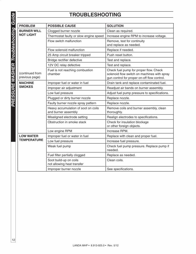
TROUBLESHOOTING
PROBLEM POSSIBLE CAUSE SOLUTION
BURNER WILL NOT LIGHT
(continued fromprevious page)
Clogged burner nozzle Clean as required.
Thermostat faulty or slow engine speed Increase engine RPM to increase voltage.
Flow switch malfunction Remove, test for continuity and replace as needed.
Flow solenoid malfunction Replace if needed.
25 Amp circuit breaker tripped Push reset button.
Bridge rectifier defective Test and replace.
12V DC relay defective Test and replace.
Fuel is not reaching combustion chamber
Check fuel pump for proper flow. Check solenoid flow switch on machines with spray gun control for proper on-off flow control.
MACHINE SMOKES
Improper fuel or water in fuel Drain tank and replace contaminated fuel.
Improper air adjustment Readjust air bands on burner assembly.
Low fuel pressure Adjust fuel pump pressure to specifications.
Plugged or dirty burner nozzle Replace nozzle.
Faulty burner nozzle spray pattern Replace nozzle.
Heavy accumulation of soot on coils and burner assembly
Remove coils and burner assembly, clean thoroughly.
Misaligned electrode setting Realign electrodes to specifications.
Obstruction in smoke stack Check for insulation blockage or other foreign objects.
Low engine RPM Increase RPM.
LOW WATERTEMPERATURE
Improper fuel or water in fuel Replace with clean and proper fuel.
Low fuel pressure Increase fuel pressure.
Weak fuel pump Check fuel pump pressure. Replace pump if needed.
Fuel filter partially clogged Replace as needed.
Soot build-up on coils not allowing heat transfer
Clean coils.
Improper burner nozzle See specifications.
LANDA MHP • 8.913-925.0 • Rev. 5/12
13
PR
ES
SU
RE
WA
SH
ER
Trou
blesh
oo
ting
Gu
ide
TROUBLESHOOTING
PROBLEM POSSIBLE CAUSE SOLUTION
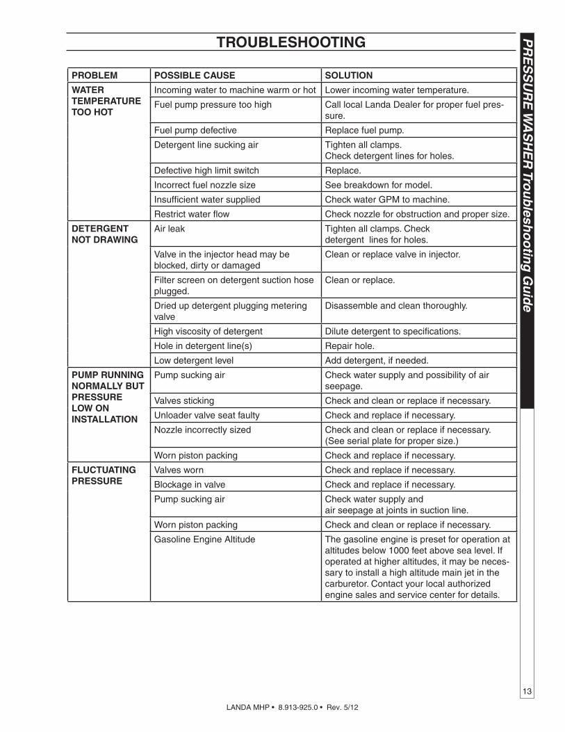
WATERTEMPERATURETOO HOT
Incoming water to machine warm or hot Lower incoming water temperature.
Fuel pump pressure too high Call local Landa Dealer for proper fuel pres-sure.
Fuel pump defective Replace fuel pump.
Detergent line sucking air Tighten all clamps. Check detergent lines for holes.
Defective high limit switch Replace.
Incorrect fuel nozzle size See breakdown for model.
Insufficient water supplied Check water GPM to machine.
Restrict water flow Check nozzle for obstruction and proper size.
DETERGENT NOT DRAWING
Air leak Tighten all clamps. Check detergent lines for holes.
Valve in the injector head may be blocked, dirty or damaged
Clean or replace valve in injector.
Filter screen on detergent suction hose plugged.
Clean or replace.
Dried up detergent plugging metering valve
Disassemble and clean thoroughly.
High viscosity of detergent Dilute detergent to specifications.
Hole in detergent line(s) Repair hole.
Low detergent level Add detergent, if needed.
PUMP RUNNING NORMALLY BUT PRESSURE LOW ON INSTALLATION
Pump sucking air Check water supply and possibility of air seepage.
Valves sticking Check and clean or replace if necessary.
Unloader valve seat faulty Check and replace if necessary.
Nozzle incorrectly sized Check and clean or replace if necessary. (See serial plate for proper size.)
Worn piston packing Check and replace if necessary.
FLUCTUATINGPRESSURE
Valves worn Check and replace if necessary.
Blockage in valve Check and replace if necessary.
Pump sucking air Check water supply and air seepage at joints in suction line.
Worn piston packing Check and clean or replace if necessary.
Gasoline Engine Altitude The gasoline engine is preset for operation at altitudes below 1000 feet above sea level. If operated at higher altitudes, it may be neces-sary to install a high altitude main jet in the carburetor. Contact your local authorized engine sales and service center for details.

LANDA MHP • 8.913-925.0 • Rev. 5/12
PR
ES
SU
RE
WA
SH
ER
Tro
ub
lesh
oo
tin
g G
uid
e
14
TROUBLESHOOTING
PROBLEM POSSIBLE CAUSE SOLUTION
PUMP NOISY
Air in suction line Check water supply and connections on suction line.
Broken or weak inlet or discharge valve springs
Check and replace if necessary.
Excessive matter in valves. Check and clean if necessary.
Worn bearings Check and replace if necessary.
PRESENCE OF WATER IN OIL
Oil seal worn Check and replace if necessary.
High humidity in air Check and change oil twice as often.
WATER DRIPPING FROM UNDER PUMP
Piston packing worn Check and replace if necessary.
O-Ring plunger retainer worn. Check and replace if necessary.
Cracked piston Check and replace if necessary.
Pump protector Lower water supply pressure. Do not run with spray gun closed longer than 5 minutes.
OIL DRIPPING Oil seal worn Check and replace if necessary.
EXCESSIVE VIBRATION IN DELIVERY LINE
Irregular functioning of valves Check and replace if necessary.
BURNER MOTOR WILL NOT RUN
Fuel pump seized Replace fuel pump.
Burner fan loose or misaligned Position correctly, tighten set screw.
Defective control switch Replace switch.
Loose wire Check and replace or tighten wiring.
Defective burner motor Replace motor
RELIEF VALVE LEAKS WATER
Relief valve defective Replace or repair.

LANDA MHP • 8.913-925.0 • Rev. 5/12
15
PR
ES
SU
RE
WA
SH
ER
OP
ER
ATO
R’S
MA
NU
AL
1. Check to see that water pump is properly lubricated.
2. Follow winterizing instructions to prevent freeze damage to pump and coils.
3. Always neutralize and flush detergent from system after use.
4. If water is known to be high in mineral content, use a water softener on your water system, or de-scale as needed.
5. Do not allow acidic, caustic or abrasive fluids to be pumped through system.
6. Always use high grade quality Landa cleaning products.
7. Never run pump dry for extended periods of time.
8. Use clean fuel — kerosene, No. 1 fuel oil, or diesel. Replace fuel filter every 100 hours of operation. Avoid water contaminated fuel as it will seize up the fuel pump.
9. If machine is operated with smoky or eye burning exhaust, coils will soot up, not letting water reach maximum operating temperature. (See section on Air Adjustments).
10. Never allow water to be sprayed on or near the engine, the burner assembly or any electrical components.
11. Periodically delime coils per instructions.
12. Check to see that engine is properly lubricated.
It is advisable, periodically, to visually inspect the burner. Check air inlet to make sure it is not clogged or blocked. Wipe off any oil spills and keep this equip-ment clean and dry.
The areas around the Landa washer should be kept clean and free of combustible materials, gasoline and other flammable vapors and liquids.
The flow of combustion and ventilating air to the burner must not be blocked or obstructed in any manner.
MAINTENANCE AND SERVICE
Unloader ValvesUnloader valves relieve pressure in the line when a spray gun is closed. Unloader valves are preset and tested at the factory before shipping. Tampering with the factory setting may cause personal injury and/or property damage, and will void the manufaturer's warranty.
Winterizing ProcedureDamage due to freezing is not covered by warranty. Adhere to the following cold weather procedures when-ever the washer must be stored or operated outdoors under freezing conditions.
PREVENTATIVE MAINTENANCE
During winter months, when temperatures drop below 32°F, protecting your machine against freezing is necessary. Store the machine in a heated room. If this is not possible then mix a 50/50 solution of antifreeze and water into a 5 gallon bucket. Place a short section of garden hose into the bucket and connect it to the machine. Elevate the bucket and turn the pump on to siphon the antifreeze through the machine. If com-pressed air is available an air fitting can be screwed into the inlet connector and, by injecting compressed air, all water will be blown out of the system.
High Limit Hot Water ThermostatFor safety, each machine is equipped with a high limit control switch. In the event the temperature of the water should exceed its operating temperature the high limit control will turn the burner off until the water cools.
PumpsUse only SAE 30 weight non-detergent oil. Change oil after first 50 hours of use. Thereafter, change oil every three months or at 500 hour intervals. Oil level should be checked through use of dipstick found on top of pump.
Cleaning Of CoilsIn alkaline water areas, lime deposits can accumulate rapidly inside the coil pipes. This growth is increased by the extreme heat build up in the coil. The best preventative for liming conditions is to use high quality cleaning detergents. In areas where alkaline water is an extreme problem, periodic use of Landa Deliming Powder (Landa Part #9-028008) will remove lime and other deposits before coil becomes plugged. (See Deliming Instructions for use of Landa Deliming Powder.)
Deliming CoilsPeriodic flushing of coils or optional float tank is rec-ommended.
Step 1 Fill a container with 4 gallons of water, then add 1 lb. of deliming powder. Mix thor-oughly.
Step 2 Remove wand assembly from spray gun and put spray gun into container or optional float tank. Secure the trigger on the spray gun into the open position.
Step 3 Attach a short section (3-5 ft.) of garden hose to machine to siphon solution from an elevated container. Turn engine on, al-lowing solution to be pumped through coils back into the container. Solution should be allowed to circulate 2-4 hours.

LANDA MHP • 8.913-925.0 • Rev. 5/12
OP
ER
ATO
R’S
MA
NU
AL
PR
ES
SU
RE
WA
SH
ER
16
Step 4 After circulating solution flush entire system with fresh water. Reinstall wand assembly to spray gun.
Removal of Soot and Heating CoilIn the heating process, fuel residue in the form of soot deposits may develop between the heating coil pipe and block air flow which will affect burner combustion. When soot has been detected on visual observation, the soot on the coil must be washed off after following the coil removal steps (See Coil Removal on page 17).
Rupture DiskIf pressure from pump or thermal expansion should exceed safe limits, the rupture disk will burst, allow-ing high pressure to be discharged through hose to ground. When the disk ruptures it will need to be replaced.
FuelUse clean fuel oil that is not contaminated with water and debris. Replace fuel filter and drain tank every 100 hours of operation. Use No. 1 or No. 2 Heating oil (ASTM D306) only. NEVER use gasoline in your burner tank. Gasoline is more combustible than fuel oil and could result in a serious explosion. NEVER use crankcase or waste oil in your burner. Fuel unit malfunction could result from contamination.
Fuel Control SystemThese machines utilize a fuel solenoid valve located on the fuel pump to control the flow of fuel to the combustion chamber. This solenoid valve, which is normally closed, is activated by a flow switch when water is flowing through it. When an operator releases the trigger on the spray gun, the flow of water through the flow switch stops, turning off the current to the fuel solenoid. The solenoid then closes, shutting off the supply of fuel to the combustion chamber. Controlling the flow of fuel in this way allows for an instantaneous burn or no burn situation, thereby eliminating high and low water temperatures, and combustion smoke normally associated with machines incorporating a spray gun.
CAUTION: Periodic inspection is recommended to insure that the fuel solenoid valve functions properly. This can be done by operating the ma-chine and checking to see that when the trigger on the spray gun is in the off position, the burner is not firing.
Fuel Pressure AdjustmentTo adjust fuel pressure, turn the adjusting screw clockwise to increase, counterclockwise to decrease. Do not exceed 200 PSI.
NOTE: When changing fuel pump, a bypass plug must be installed in return port or fuel pump will not prime.
Electrode Setting
Burner NozzleKeep the tip free of surface deposits by wiping it with a clean, solvent-saturated cloth, being careful not to plug or enlarge the nozzle. For maximum efficiency, replace the nozzle each season.
Beckett Burner Air AdjustmentThe oil burner on this machine is preset for operation at altitudes below 1000 feet. If operated at higher altitudes, it may be necessary to adjust the air band setting. Adjust air band for a #1 or #2 smoke spot on the Bacharach scale. A one-time initial correction for your location will pay off in economy, performance, and extended service life. If a smoky or eye-burning exhaust is being emitted from the stack, two things should be checked. First, check the fuel to be certain that kerosene or No. 1 home heating fuel is being used. Next, check the air adjustment on the burner.
PREVENTATIVE MAINTENANCE
5/32"
1/4"
Electrode
Nozzle5/32"
Air Band
Fuel Pump
Air Adjustment
Screw

LANDA MHP • 8.913-925.0 • Rev. 5/12
17
PR
ES
SU
RE
WA
SH
ER
OP
ER
ATO
R’S
MA
NU
AL
Initial Air Adjustments: Allow sufficient air to obtain a clean burning flame by loosening the lock screws and moving the air shutter and if necessary the bulk air band.
Reduce the air supply until the flame tips appear slightly smoky, then increase the air just enough to cause the flame tips to appear absolutely clean.
Landa Sure Fire Oil BurnerBurner Air Adjustment: The oil burner on this machine is preset for operation at altitudes below 1000 feet. If operated at higher altitudes, it may be neces-sary to adjust the air band for a #1 or #2 smoke spot on the Bacharach scale.
To adjust, start machine and turn burner ON. Loosen two locking screws found on the air band and close air band until black smoke appears from burner exhaust vent. Note air band position. Next, slowly open the air band until white smoke just starts to appear. Turn air band halfway back to the previously noted position. Tighten locking screws.
Burner Air Adjustment
Reference Numbers
Air Band Locking Screws
Air Band
CAUTION: If white smoke appears from burner exhaust vent during start-up or operation, discontinue use and readjust air bands.
NOTE: If a flue is installed, have a professional serviceman adjust your burner for a #1 or #2 smoke spot on the Bacharach scale.
PREVENTATIVE MAINTENANCE
Coil RemovalRemoval of coil because of freeze breakage, or to clean soot from it can be done quickly and easily.
Step 1 Disconnect hose from pump to inlet side of the coil.
Step 2 Disconnect electr ical connection to the thermostat.
Step 3 Remove quick coupler from discharge side of coil.
Step 4 Remove burner assembly f rom combustion chamber.
Step 5 Remove the 3-3/8" bolts from each side of coil and tank assembly (these bolts are used to fasten tank to chassis).
Step 6 Disconnect 1/2" pipe nipples from inlet and discharge side of coil.
Step 7 Remove top tank wrap exposing insulation and coil and fold back insulation.
Step 8 Remove bolts that hold down coil to bottom wrap.
Step 9 Remove coil.
Replace or repair any insulation found to be torn or broken.
Coil ReinstallationReinstal l new or cleaned coi l by reversing the steps above.
Final Note —The DC motors used on 12V DC burners can draw as much as 20 amps! For the burner to run properly, the battery and engine charging system must be kept in good condition, and the engine must run fast enough to adequately charge the battery. Do not throttle down the engines for any length of time.

LANDA MHP • 8.913-925.0 • Rev. 5/12
OP
ER
ATO
R’S
MA
NU
AL
PR
ES
SU
RE
WA
SH
ER
18
This pressure washer was produced with the best available materials and quality craftsmanship. However, you as the owner have certain responsibilities for the correct care of the equipment. Attention to regular preventa-tive maintenance procedures will assist in preserving the performance of your equipment. Contact your Landa dealer for maintenance. Regular preventative maintenance will add many hours to the life of your pressure washer. Perform maintenance more often under severe conditions.
OIL CHANGE RECORD
PREVENTATIVE MAINTENANCE
MAINTENANCE SCHEDULE
Engine Oil Inspect Daily
Change Every 25 hours
Filter Every 50 hours
Air CleanerInspect Every 50 hours or monthly
Clean Every 3 months
Battery Level Check monthly
Engine Fuel Filter 500 hours or 6 months
Spark Plug Maintenance 500 hours or 6 months
Clean Fuel Tank(s) Annually
Replace Fuel Lines Annually
Pump Oil (Non-detergent 10/40W)
Inspect Oil level daily
Change After first 50 hours, then every 500 hours or annually
Clean Burner Filter Monthly (More often if fuel quality is poor)
Remove Burner Soot Annually
Burner Adjustment/Cleaning Annually
Replace Burner Nozzle Annually
Descale Coil Annually (More often if required)
Replace High Pressure Nozzle Every 6 months
Replace Quick Connects Annually
Clean Water Screen/Filter Weekly
Replace HP Hose Annually
Date Oil Changed Month/Day/Year
Estimated Operating Hours Since Last
Oil ChangeDate Oil Changed Month/Day/Year
Estimated Operating Hours Since Last
Oil Change
LANDA MHP • 8.913-925.0 • Rev. 5/12
19
PR
ES
SU
RE
WA
SH
ER
OP
ER
ATO
R’S
MA
NU
AL
89139250-9
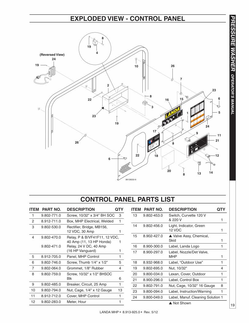
ITEM PART NO. DESCRIPTION QTY 1 9.802-771.0 Screw, 10/32" x 3/4" BH SOC 3
2 8.912-711.0 Box, MHP Electrical, Welded 1
3 9.802-530.0 Rectifier, Bridge, MB156, 12 VDC, 30 Amp 1
4 9.802-470.0 Relay, P & B/VF41F11, 12 VDC, 40 Amp (11, 13 HP Honda) 1 9.802-471.0 Relay, 24 V DC, 40 Amp (16 HP Vanguard) 1
5 8.912-705.0 Panel, MHP Control 1
6 9.802-746.0 Screw, Thumb 1/4" x 1/2" 5
7 9.802-064.0 Grommet, 1/8" Rubber 4
8 9.802-759.0 Screw, 10/32" x 1/2" BHSOC Blk 6
9 9.802-485.0 Breaker, Circuit, 25 Amp 1
10 9.802-794.0 Nut, Cage, 1/4" x 12 Gauge 13
11 8.912-712.0 Cover, MHP Control 1
12 9.802-283.0 Meter, Hour 1
ITEM PART NO. DESCRIPTION QTY 13 9.802-453.0 Switch, Curvette 120 V & 220 V 1
14 9.802-456.0 Light, Indicator, Green 12 VDC 1
15 8.902-427.0 Valve Assy, Chemical, Skid 1
16 8.900-300.0 Label, Landa Logo 1
17 8.900-297.0 Label, Nozzle/Det Valve, MHP 1
18 8.932-968.0 Label, “Outdoor Use” 1
19 9.802-695.0 Nut, 10/32" 4
20 9.800-034.0 Lexan, Cover, Outdoor 1
21 8.900-296.0 Label, Control Box 1
22 9.802-791.0 Nut, Cage, 10/32" 16 Gauge 8
23 9.800-094.0 Label, Instruction/Warning 1
24 9.800-049.0 Label, Manuf. Cleaning Solution 1
Not Shown
10
2
3
4
5
6
7
8
911
12
13 14
1516
17
21
8
22
8
22
18
24
1
19
23
19
(Reversed View)
19
8
6
26
26
EXPLODED VIEW - CONTROL PANEL
CONTROL PANEL PARTS LIST
23
24
20

LANDA MHP • 8.913-925.0 • Rev. 5/12
OP
ER
ATO
R’S
MA
NU
AL
PR
ES
SU
RE
WA
SH
ER
20
EXPLODED VIEW - LEFT SIDE
EXPOSED PULLEYS AND
BELTS CAN CAUSE IN
JURY
PRECAUCION/AVERTISSEMENT
WARNING
EXPOSED PULLEYS AND
BELTS CAN CAUSE INJURY
PRECAUCION/AVERTISSEMENT
WARNING
89139250-2
1
65
2
3
13
7
6
4
5
32
85
19
20
211815
16
17
28
76
33
73 70
74
7224
35
26
25
23
22
62
60
59
64
9
10
8
1211
115
91
116
71
77
90
94
90
91
17
35
92
15 111
113
113
21
114
11265

LANDA MHP • 8.913-925.0 • Rev. 5/12
21
PR
ES
SU
RE
WA
SH
ER
OP
ER
ATO
R’S
MA
NU
AL
EXPLODED VIEW - RIGHT SIDE
89139250-3
37
58
6588
56
50
36
24 49
66
44
83
89, 90,9463
63
48
47
100
9596
9798
55
57
107
24
39
46
45
5469
75 43
4267
68
4143
42
7880
53
52
828492
57
87,90,93
1410199
9089
34
79
51
Wheel Kit(Optional)
For Detail See
Control Panel Illus.
105
103
82
102
81
30
39
106
40
38
104
65
86
27
108
61
29
82
61
109
110
110
11036
36
31

LANDA MHP • 8.913-925.0 • Rev. 5/12
OP
ER
ATO
R’S
MA
NU
AL
PR
ES
SU
RE
WA
SH
ER
22
EXPLODED VIEW PARTS LIST
ITEM PART NO. DESCRIPTION QTY 1 8.912-186.0 Wrap, Top (All) Yellow 1
2 9.802-071.0 Trim, 1/16", Black, 750 - B2 3 ft.
3 9.802-766.0 Screw, 3/8" x 1" HX 6
4 8.717-424.0 Insulation, Gasket, Skid, Stackless Top 1
5 8.911-304.0 Exhaust, Plate 1
6 8.718-812.0 Screw, Cap, 10/32" x 3/4" SS 4
7 9.802-894.0 Insulation, Burner Head, w/Hole 1
8 9.802-896.0 Insulation, Blanket, No Foil, 24" x 57" 1
9 9.802-902.0 Insulation, Blanket Die Cut, 28" x 24" 1
10 8.912-239.0 Coil Replacement Schedule 80 w/Aluminum Steel Wrap 1
11 8.912-188.0 Wrap, Bottom Yellow 1
12 9.802-883.0 Insulation, Front Head, No Hole 1
13 9.802-653.0 Gasket, Mounting 2
14 9.803-136.0 Retainer, Pump Take Up 1
15 8.706-958.0 Hose Barb, 1/4" Barb x 1/4" ML Pipe 2
16 6.390-126.0 Clamp, Hose, .46-, .54 ST (11, 13 HP) 6 (16 HP) 8
17 9.802-254.0 Hose, 1/4", Push-On 7 ft.
18 8.709-152.0 Filter, Fuel, Disposable 1
19 8.933-009.0 Gasket, Burner Plate 2
20 9.803-132.0 Insulation Retainer Plate 2
21 9.802-015.0 Nipple, 1/2" x 4", Galvanized 2
22 8.918-432.0 Nipple, 3/8" x 3/8" NPT, St 1
23 9.184-030.0 Spacer, Rupture Disk 1
24 9.802-794.0 Nut, Cage, 1/4" x 12 Gauge 10
25 9.149-003.0 Manifold, Coil Outlet 1
26 8.712-185.0 Switch, Snap, 225 DR HI Limit 1
27 9.802-254.0 Hose, Push-On, (16 HP) 5.5 ft.
28 9.802-043.0 Elbow, 1/2" JIC x 1/2 Fem, 90° 1
29 8.706-168.0 Elbow, 3/8" Male 1
30 8.933-006.0 Switch, Flow MV60 1
31 9.800-080.0 Label, Danger, Cool Engine 1
32 9.802-791.0 Nut, Cage 10/32" x 16 Gauge 4
33 8.918-432.0 Hose, 18" x 3/8", Pressure Loop 1
34 8.912-705.0 Panel, MHP Control 1
35 9.802-754.0 Screw, 1/4" x 1/2" HH, NC, Whiz Loc 4
36 9.802-746.0 Screw, Thumb 1/4" x 1/2" 10
ITEM PART NO. DESCRIPTION QTY 37 9.802-753.0 Screw, 1/4" x 3/4" HH, NC, Whiz Loc 2
38 8.707-254.0 Pump Protector, 3/8" PTP 1
39 See Pump Specifications, Page 28-29 1
40 8.750-299.0 Unloader, VRT 3, 8 GPM @ 4500 PSI 1
41 8.706-652.0 Box, Battery 1 9.802-091.0 Plate, Battery Box, Small, Polypro 1
42 9.803-541.0 Bolt, 5/16" x 1/2", Button Head 4
43 9.803-542.0 Washer, 5/16", Star 4
44 9.800-001.0 Label Gasoline Only (16, 20HP) 1
45 8.706-611.0 Tank, Fuel, 5 Gal, Poly, Yellow 1
46 8.706-604.0 Tank, Fuel, 5 Gal, Red (16 HP) 1
47 9.802-193.0 Gasket, Fuel Tank, 7" (11,13 HP) 1 (16 HP) 2
48 9.802-054.0 Elbow, Fuel Tank 1
49 9.802-089.0 Cap, Fuel Tank, Plastic, H60-AR (11, 13 HP) 1 (16 HP) 2
50 See Engine Specifications, Page 28-29 1
51 9.802-714.0 Bolt, 5/16" x 1-3/4"", NC HH 4
52 8.912-704.0 Cage, MHP, Assembly 1
53 9.802-794.0 Nut, Cage, 1/4" x 12 Gauge 11
54 9.803-532.0 Isolator, 5/16", F x F, 1" 4
55 9.802-776.0 Nut, 5/16", ESNA, NC 4
56 8.912-707.0 Panel, MHP Rear 1
57 8.718-980.0 Washer, 5/16" Flat 8
58 8.719-968.0 Holder, Wand, Zinc 2
59 8.706-207.0 Elbow, 3/8" Street 1
60 8.707-019.0 Hose Barb, 1/2" Barb x 3/8" MPT, Push-On 1
61 9.802-039.0 Elbow, 1/2" JIC x 3/8", 90° 2
62 9.802-259.0 Hose, 1/2" Push-On 1.75 ft.
63 8.706-496.0 Diptube, Plastic (11, 13 HP) 1 (16 HP) 2 9.802-259.0 Bushing, Rubber, Nitrate (11, 13 HP) 2 (16 HP) 3
64 8.725-944.0 Rupture Disk Assy, 8000 PSI 1

LANDA MHP • 8.913-925.0 • Rev. 5/12
23
PR
ES
SU
RE
WA
SH
ER
OP
ER
ATO
R’S
MA
NU
AL
EXPLODED VIEW PARTS LIST
ITEM PART NO. DESCRIPTION QTY 65 9.800-006.0 Label, "Hot/Caliente" 4
66 9.800-002.0 Label, Use Only Kerosene/Diesel 1
67 9.802-146.0 Swivel, 1/2" MP x 3/4" GHF 1
68 8.707-055.0 Strainer, Inlet Garden Hose 1
69 8.718-618.0 Bolt, 5/16" x 3/4" 4
70 See Pump Pulley Specifications, Pages 28-29
71 See Engine Pulley Specifications, Pages 28-29
72 See Engine Bushing Specifications, Pages 28-29
73 See Pump Bushing Specifications, Pages 28-29
74 See Belt Specifications, Pages 28-29
75 8.912-714.0 Bracket, Battery 1
76 8.912-715.0 Belt Guard (11, 13, 16 HP) 1
77 8.912-719.0 Plate, Face (11, 13, 16 HP) 1
78 9.802-151.0 Swivel, 1/2" JIC, Push-On 2
79 8.912-722.0 Foot, MHP 4 9.802-767.0 Screw, 3/8" x 3/4" Whiz Loc 8 9.802-781.0 Nut, 3/8" Whiz Loc 8
80 9.802-259.0 Hose, 1/2", Push-on 1.5 ft.
81 8.706-829.0 Elbow, Street, Brass 1
82 9.802-128.0 Nipple, 1/2" JIC x 1/2" Pipe (Landa Pump) 3
83 8.912-699.0 Strap, MHP Fuel Tank (11, 13 HP) 2 (16 HP) 1 8.912-701.0 Strap, MHP Fuel Tank, Long (16 HP) 1
84 9.803-131.0 Rail, Pump Combo 1
85 9.802-559.0 Burner Assy, Beckett, 12 VDC 1 8.918-919.0 Burner, Landa Sure Fire 12VDC 1 9.802-668.0 Electrode, Pair Beckett 1
9.802-638.0 Motor, Burner Beckett 1 9.802-562.0 Pump, Fuel Beckett 1 9.802-639.0 Solenoid Coil, 12V 1 9.802-636.0 Blower Wheel Beckett 1 9.802-637.0 Coupling, Fuel Beckett 1 9.802-663.0 Ignitor, Assembly Beckett 1 8.717-273.0 Nozzle, Burner 2.00 x 90° B (4-3000, 4-3500) 1
86 8.718-980.0 Washer, 5/16", Flat 4
87 9.802-789.0 Nut, 3/8" Hex 2
ITEM PART NO. DESCRIPTION QTY 88 9.802-867.0 Guard, Muffler 16 HP (Vanguard) 1 9.802-868.0 Brace (Vanguard) Muffler 9.802-672.0 Muffler (Vanguard) 1
89 8.725-395.0 Nut, 3/8" ESNA 9
90 9.802-807.0 Washer, 3/8" Flat 30
91 9.802-781.0 Nut, 3/8", Whiz Loc 5
92 9.802-720.0 Bolt, 3/8" x 1" NC HH 8
93 9.802-733.0 Bolt, 3/8" x 3-1/2", Tap 2
94 9.802-727.0 Bolt, 3/8" x 1-3/4", Tap 3
95 9.802-154.0 Push-on, Male (11, 13 HP) 1 8.707-019.0 Push-on, 3/8" Male (16 HP) 1
96 9.802-259.0 Hose, 1/2" Push-on (16 HP) 5" 9.802-254.0 Hose, 1/4" Push-on (11, 13 HP) 5"
97 9.802-153.0 Swivel, 1/4" JIC FEM, Push-on (11, 13 HP) 1 9.802-151.0 Swivel, 1/2" JIC FEM, Push-on (16 HP) 1
98 9.802-126.0 Plug, 1/2" JIC, Flare (16 HP) 1 9.802-125.0 Plug, 1/4" JIC, Flare (11,13 HP) 1
99 9.802-776.0 Nut, 5/16", ESNA, NC 4
100 8.912-723.0 Shield, Heat, MHP 1
101 9.802-813.0 Washer, 5/8", Lock 4
102 8.706-797.0 Nipple, 1/2" Hex 1
103 8.706-844.0 Tee, 1/2" Female, Pipe 1
104 8.724-844.0 Switch, Reed Replacement, MV60 1
105 9.802-151.0 Swivel, 1/2" JIC Fem, Push-On 2
106 9.802-259.0 Hose, 1/2", Push-On 1.42 ft.
107 8.916-090.0 Label, Landa Logo 1
108 9.802-129.0 Elbow, 1/2" JIC x 3/8", 90° 1
109 9.801-252.0 Label, Maintain Engine Speed 1
110 8.718-976.0 Washer, 1/4" Retainer 10
111 8.706-216.0 Tee, 1/2 Female, Steel 1
112 8.706-248.0 Plug, 3/8" Allen 1
113 8.932-965.0 Label, Warning Exposed Pulley 2
114 9.196-012.0 Screw, 10-24 x 1/4 1
115 8.706-996.0 Adapter, 1/4" x 1/4" 1
116 9.801-265.0 Label, Landa Sure Fire 1
Not Shown

LANDA MHP • 8.913-925.0 • Rev. 5/12
OP
ER
ATO
R’S
MA
NU
AL
PR
ES
SU
RE
WA
SH
ER
24
89139250-1
22
17
20
2116
11
22 23
13
14
1519
18 10
5
4
3
1
2
2
26
25
12
30
30
29
24
9
Optional Wheel Kit Assembly
22
22
Float Tank Option
Landa Pump
With Float Tank
Option
Detergent Valve Option
7
8
6
27
EXPLODED VIEW - DETERGENT/FLOAT TANK
28

LANDA MHP • 8.913-925.0 • Rev. 5/12
25
PR
ES
SU
RE
WA
SH
ER
OP
ER
ATO
R’S
MA
NU
AL
ITEM PART NO. DESCRIPTION QTY 1 8.707-317.0 Valve/Control, Metering 1 9.802-810.0 Washer, 5/8" SAE Flat Zinc 1 8.719-011.0 Washer, 5/8" Interval Star Zinc 1
2 8.706-958.0 Hose Barb, 1/4" Barb x 1/4" Pipe, 90° 2
3 6.390-126.0 Clamp, Hose, .46-, .54 ST 2
4 9.802-132.0 Elbow, 3/4" JIC x 1/2" Male 90° 1
5 9.802-254.0 Hose, 1/4", Push-On 2.5 ft.
6 9.802-152.0 Swivel, 3/4" JIC Fem, Push-On 1
7 8.916-090.0 Label, Landa Logo 1
8 8.706-958.0 Hose Barb, 1/4" Barb x 1/4" ML Pipe, 90° 1
9 8.912-233.0 Lid & Hinges, Plastic Ft. Tank 1
10 9.802-185.0 Valve, Fluidmaster 400A Float 2
11 9.802-084.0 Tank, Plastic Universal Float 1
ITEM PART NO. DESCRIPTION QTY 12 8.707-058.0 Strainer, 1/4" Hose Barb 1
13 8.707-061.0 Strainer, 1/2" Basket 1
14 9.802-131.0 Elbow, 1/2" JIC x 1/2", 90° 1
15 8.707-000.0 Connector, 1/2" Anchor 1
16 8.719-039.0 Washer, 1-3/16" x 2-1/4", STL RBR 1
17 8.707-020.0 Push-On, 3/4" x 1/2" Male 1
18 9.802-822.0 Screw, 5/16" - 18 x 1-1/2" SS, Button Socket 1
19 9.802-106.0 Plug, Float Tank 1
20 9.802-824.0 Washer, 5/16" SS 1
21 9.802-823.0 Nut, 5/16" - 18, Wing SS 1
22 9.802-258.0 Inlet Hose, Supply Water, 45" 2
23 9.802-261.0 Hose, 3/4", Push-On 2.5 ft.
24 9.802-134.0 Tee, 1/2" x 1/2" JIC 51# 1
25 9.802-251.0 Tube, 1/4" x 1/2" Clear Vinyl 8 ft.
26 8.706-829.0 Elbow, 1/2" Street, Brass 1
27 9.802-119.0 Cross, 1/2" Female, Cast 1
28 8.706-915.0 Bushing, 1/2 x 1/4 Brass 1
29 8.706-965.0 Hose Barb 1/4" x Barb x 3/8" NPT 1
30 9.802-254.0 Hose, 1/4" Push-on 6'
Not Shown
DETERGENT/FLOAT TANK PARTS LIST

LANDA MHP • 8.913-925.0 • Rev. 5/12
OP
ER
ATO
R’S
MA
NU
AL
PR
ES
SU
RE
WA
SH
ER
26
ITEM PART NO. DESCRIPTION QTY 1 9.802-166.0 Coupler, 3/8" Female 1 9.802-100.0 Quick Coupler O-Ring Lg 1
2 8.739-213.0 Hose, 3/8" x 50', 2 Wire Tuff Skin 1
3 8.751-234.0 Gun, Landa, L1050 5000 PSI, 10.4 GPM 1
4 8.711-293.0 Wand, VP, Zinc (AL 344) w/Coupler, w/Soap Nozzle 1 83-SSVPKIT Repair Kit, Wand, AR, SS, Seat (AL344) 1
5 8.712-346.0 Nozzle, SAQC MEG, 1504, Yellow (4-3000, 4-3500) 1 8.712-347.0 Nozzle, SAQC MEG 2504, Green (4-3000, 4-3500) 1 8.712-348.0 Nozzle, SAQC MEG 4004 White (4-3000, 4-3500) 1 8.712-345.0 Nozzle, SAQC MEG 0004, Red (4-3000, 4-3500) 1
ITEM PART NO. DESCRIPTION QTY 5 8.712-350.0 Nozzle, SAQC MEG 1545 Yellow, General Pump (5-3500) 1 8.712-351.0 Nozzle, SAQC MEG 2545 Green, General Pump (5-3500) 1 8.712-352.0 Nozzle, SAQC MEG 4045 White, General Pump (5-3500) 1 8.712-349.0 Nozzle, SAQC MEG 0045 Red, General Pump (5-3500) 1
6 9.802-286.0 Brass Soap Nozzle Only, 1/8" 1
7 9.802-225.0 Detergent Injector (All Models) 1
8 9.802-165.0 Coupler, 1/4" Female 1 9.802-096.0 Quick Coupler O-Ring, Sm 1
Not Shown
6,8 5
7
34
1
2
EXPLODED VIEW - HOSE & SPRAY GUN
HOSE & SPRAY GUN PARTS LIST

LANDA MHP • 8.913-925.0 • Rev. 5/12
27
PR
ES
SU
RE
WA
SH
ER
OP
ER
ATO
R’S
MA
NU
AL
ITEM PART NO. DESCRIPTION QTY 1 9.802-216.0 Injector, Detergent, Non Adjust, #3 1
2 6.390-126.0 Clamp, Hose, .46-, .54 ST 2
3 9.802-251.0 Tube, 1/4" x 1/2", Clear Vinyl 6 ft.
4 8.707-057.0 Strainer, 1/4", Hose Barb 1
3
21
4
2
9.802-225.0
EXPLODED VIEW - DETERGENT INJECTOR
DETERGENT INJECTOR PARTS LIST

LANDA MHP • 8.913-925.0 • Rev. 5/12
PR
ES
SU
RE
WA
SH
ER
Sp
ecifi
cati
on
s
28
SPECIFICATIONS
Model Model Part # Pulley Pulley Part # Bushing Bushing Part # Belt Size/Qty Model Belt Part # Model Type Part # Pulley Pulley Part # Bushing Part#
MHP4-30324E LT4035 8.904-869.0 2AK84H 9.802-375.0 25mm 9.802-403.0 AX38 (2) 4-30324E 9.802-410.0 GX340 (389cc) HONDA 8.750-578.0 2AK30 9.803-298.0 HX1" 5-11100
MHP4-35224E LT4035 8.904-869.0 2BK90 8.715-593.0 25mm 9.802-403.0 BX44 (2) 4-35224E 8.715-705.0 Vanguard (479cc) BRIGGS 9.802-325.0 2BK32 8.715-576.0 HX1" 5-11100
MHP4-35324E LT4035 8.904-869.0 2BK90 8.715-593.0 25mm 9.802-403.0 BX39 (2) 4-35324E 5-604039 GX390 (389cc) HONDA 8.750-579.0 2BK32 8.715-576.0 HX1" 5-11100
PARTS SPECIFICATIONS: LANDA PUMP
PUMP ENGINE

LANDA MHP • 8.913-925.0 • Rev. 5/12
29
PR
ES
SU
RE
WA
SH
ER
Sp
ecificatio
ns
Model Model Part # Pulley Pulley Part # Bushing Bushing Part # Belt Size/Qty Model Belt Part # Model Type Part # Pulley Pulley Part # Bushing Part#
MHP4-30324E LT4035 8.904-869.0 2AK84H 9.802-375.0 25mm 9.802-403.0 AX38 (2) 4-30324E 9.802-410.0 GX340 (389cc) HONDA 8.750-578.0 2AK30 9.803-298.0 HX1" 5-11100
MHP4-35224E LT4035 8.904-869.0 2BK90 8.715-593.0 25mm 9.802-403.0 BX44 (2) 4-35224E 8.715-705.0 Vanguard (479cc) BRIGGS 9.802-325.0 2BK32 8.715-576.0 HX1" 5-11100
MHP4-35324E LT4035 8.904-869.0 2BK90 8.715-593.0 25mm 9.802-403.0 BX39 (2) 4-35324E 5-604039 GX390 (389cc) HONDA 8.750-579.0 2BK32 8.715-576.0 HX1" 5-11100
SPECIFICATIONS
CONTROLSENGINE (CON'T)
LANDA MHP • 8.913-925.0 • Rev. 5/12
OP
ER
ATO
R’S
MA
NU
AL
PR
ES
SU
RE
WA
SH
ER
30
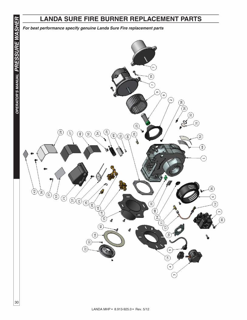
For best performance specify genuine Landa Sure Fire replacement parts
LANDA SURE FIRE BURNER REPLACEMENT PARTS

LANDA MHP • 8.913-925.0 • Rev. 5/12
31
PR
ES
SU
RE
WA
SH
ER
OP
ER
ATO
R’S
MA
NU
AL
For best performance specify genuine Landa Sure Fire replacement parts
LANDA SURE FIRE BURNER REPLACEMENT PARTS
Item
#P
art
#D
escr
ipti
on
Qty
Item
#P
art
#D
escr
ipti
on
Qty
18.
919-
050.
0B
UR
NE
R H
OU
SIN
G A
SS
EM
BLY
125
8.75
0-83
0.0
PLU
G, H
OLE
0.2
85 P
LAS
TIC
1
28.
751-
160.
0A
IR G
UID
E26
8.75
1-13
4.0
PLU
G, 1
/8"
NP
T x
HE
X S
HO
ULD
ER
1
38.
700-
758.
0F
UE
L P
UM
P, S
UN
TE
C A
2VA
-310
6 12
-24V
SO
L1
278.
918-
454.
0G
AS
KE
T, J
UN
CT
ION
BO
X1
38.
700-
759.
0F
UE
L P
UM
P, S
UN
TE
C A
2VA
-310
6 12
0V S
OL
128
8.75
0-54
2.0
CO
VE
R, J
UN
CT
ION
BO
X1
38.
700-
760.
0F
UE
L P
UM
P, S
UN
TE
C A
2VA
-310
6 23
0V S
OL
129
8.75
0-11
6.0
BLO
CK
, TE
RM
INA
L, 5
PO
LE1
38.
753-
000.
0F
UE
L P
UM
P, D
AN
FO
SS
071
N12
981
308.
750-
817.
0LI
GH
T, IN
DIC
ATO
R, G
RE
EN
14V
2
48.
750-
762.
0C
OIL
, SO
LEN
OID
DA
NF
OS
S 2
30V
130
8.75
0-81
8.0
LIG
HT,
IND
ICAT
OR
, GR
EE
N 2
8V1
48.
750-
763.
0C
OIL
, SO
LEN
OID
DA
NF
OS
S 1
15V
130
8.75
0-81
9.0
LIG
HT,
IND
ICAT
OR
, GR
EE
N 1
25V
1
48.
750-
764.
0C
OIL
, SO
LEN
OID
DA
NF
OS
S 1
2-24
V1
308.
750-
820.
0LI
GH
T, IN
DIC
ATO
R, G
RE
EN
250
V1
58.
750-
765.
0C
AB
LE, S
OLE
NO
ID C
OIL
, DA
NF
OS
S1
318.
750-
784.
0S
ITE
GLA
SS
1
5a8.
750-
783.
0M
OU
NT
ING
KIT
, FLA
NG
E/H
UB
, DA
NF
OS
S1
328.
750-
785.
0R
ING
, PU
SH
ON
INT
ER
NA
L, 1
305-
112
1
68.
750-
541.
0A
IR B
AN
D1
338.
733-
001.
0S
CR
EW
, 8 x
1/4
" H
I LO
W T
HR
EA
D C
UT,
PP
H2
78.
750-
517.
0M
OTO
R, 1
/6 H
P 1
15V
60H
z1
348.
718-
762.
0S
CR
EW
, 8-3
2 X
1/2
", M
PH
RD
H P
L2
78.
750-
518.
0M
OTO
R, 1
/6 H
P 2
30V
60H
z1
358.
752-
137.
0W
AS
HE
R, C
OP
PE
R1
78.
751-
074.
0M
OTO
R, 1
/7 H
P 1
2VD
C A
ME
TE
K1
368.
718-
810.
0S
CR
EW
, 10/
32 x
1/2
", W
HIZ
LO
C F
LAN
GE
6
88.
750-
543.
0C
OU
PLI
NG
, FLE
X, 1
/2"
x 5/
16"
137
8.75
0-77
0.0
SC
RE
W, 1
0/32
x 5
/8",
WH
IZ L
OC
FLA
NG
E3
88.
751-
073.
0C
OU
PLI
NG
, FLE
X, 5
/16"
x 5
/16"
138
8.75
0-81
6.0
SC
RE
W, 1
0/32
X 1
/4"
GR
OU
ND
ING
1
9 8
.750
-520
.0
FAN
, 4.5
3" X
2.4
2", 1
/2"
BO
RE
, F11
5-62
S1
398.
750-
768.
0S
CR
EW
, 1/4
-20
x 1"
, WH
IZ L
OC
FLA
NG
E4
98.
751-
072.
0FA
N, 4
.53"
x 2
.42"
x .3
13 B
OR
E, F
115-
625
140
8.75
0-77
1.0
SC
RE
W, 1
/4-2
0 X
1/2
", P
HIL
FH
MS
4
118.
750-
547.
0C
ON
NE
CTO
R, 3
7 D
EG
FLA
RE
X 1
/8"
NP
T, L
ON
G1
42—
LAB
EL,
BR
AN
D N
AM
E1
128.
750-
545.
0C
ON
NE
CTO
R, 3
7 D
EG
FLA
RE
X 1
/8"
NP
T1
439.
801-
268.
0LA
BE
L, D
ISC
ON
NE
CT
PO
WE
R S
UP
PLY
1
138.
749-
000.
0F
UE
L LI
NE
AS
SE
MB
LY1
44—
LAB
EL,
SE
RIA
L P
LAT
E1
148.
752-
034.
0F
LAN
GE
, KN
A B
UR
NE
R, 1
" T
UB
E A
SS
Y1
469.
807-
339.
0LA
BE
L, W
IRIN
G D
IAG
RA
M, B
UR
NE
R 1
15V
-115
V1
158.
752-
035.
0F
LAN
GE
, KN
A B
UR
NE
R, 3
" T
UB
E A
SS
Y1
469.
807-
340.
0LA
BE
L, W
IRIN
G D
IAG
RA
M, B
UR
NE
R 2
30V
-230
V4
168.
750-
539.
0G
AS
KE
T, F
LAN
GE
146
9.80
7-34
1.0
LAB
EL,
WIR
ING
DIA
GR
AM
, BU
RN
ER
230
V-1
15V
1
188.
750-
526.
0G
UN
, ELE
CT
RO
DE
/ N
OZ
ZLE
, 3"
146
9.80
7-34
2.0
LAB
EL,
WIR
ING
DIA
GR
AM
, BU
RN
ER
115
V-2
4V1
198.
750-
525.
0G
UN
, ELE
CT
RO
DE
/ N
OZ
ZLE
, 1"
146
9.80
7-34
3.0
LAB
EL,
WIR
ING
DIA
GR
AM
, BU
RN
ER
230
V-2
4V1
20V
arie
sN
OZ
ZLE
, FU
EL
146
9.80
7-34
4.0
LAB
EL,
WIR
ING
DIA
GR
AM
, BU
RN
ER
12V
DC
1
218.
750-
778.
0E
LEC
TR
OD
E, I
GN
ITIO
N, A
C1
489.
801-
274.
0LA
BE
L, B
UR
NE
R L
IGH
TS
1
218.
751-
342.
0E
LEC
TR
OD
E, I
GN
ITIO
N, D
C1
498.
919-
105.
0P
LAT
E, T
ER
MIN
AL
BLO
CK
NU
MB
ER
S1
228.
750-
779.
0C
ON
E, A
IR F
41
508.
716-
451.
0T
ER
MIN
AL,
JU
MP
ER
SPA
DE
1
228.
750-
782.
0C
ON
E, A
IR F
61
519.
802-
510.
0C
AB
LE, T
IE, 4
" B
LAC
K2
228.
750-
780.
0C
ON
E, A
IR F
121
529.
807-
348.
0LA
BE
L, C
LEA
R M
YLA
R1
228.
750-
781.
0C
ON
E, A
IR F
221
539.
807-
345.
0LA
BE
L, IG
NIT
ER
120
V1
238.
919-
114.
0IG
NIT
OR
, BU
RN
ER
120
V1
539.
807-
346.
0LA
BE
L, IG
NIT
ER
230
V1
23 8
.919
-115
.0
IGN
ITO
R, B
UR
NE
R 2
30V
153
9.80
7-34
7.0
LAB
EL,
IGN
ITO
R 1
2VD
C1
238.
919-
116.
0IG
NIT
OR
, BU
RN
ER
12V
DC
154
8.75
1-35
4.0
GA
SK
ET,
BU
RN
ER
TU
BE
1
248.
751-
165.
0P
LUG
, HO
LE 0
.875
PLA
ST
IC1

LANDA MHP • 8.913-925.0 • Rev. 5/12
OP
ER
ATO
R’S
MA
NU
AL
PR
ES
SU
RE
WA
SH
ER
32
TORQUE SPECS
Item # Ft.-Lbs.
17 75
18 45
27 18
37 10
48 30
53 7.6
LT.1 SERIES PUMP EXPLODED VIEW
LT.1 SERIES PUMP EXPLODED VIEW PARTS LIST
8.904-869.0 LT4035.1 Right8.904-870.0 LT4035.1 Left 8.904-871.0 LT4040.1 Right8.904-872.0 LT4040.1 Left8.904-874.0 LT5030.1 Right8.904-879.0 LT5030.1 Left8.904-881.0 LT6035.1 Right8.904-883.0 LT6035.1 Left
ITEM PART NO. DESCRIPTION QTY 19 9.802-890.0 Washer 8
20 9.803-198.0 Copper Washer 3/8" 1
21 9.802-925.0 Brass Plug 3/8" 1
26 9.802-884.0 Washer 8
27 9.802-944.0 Hexagonal Screw 8
28 9.803-182.0 Closed Bearing Housing 1
29 9.803-186.0 O-Ring Ø2.62 x 71.12 2
30 9.803-160.0 Roller Bearing, Tapered 2
31 9.803-148.0 Crankshaft (GT4040.1, 5030.1, 6035.1) 1 9.803-149.0 Crankshaft (GT 4035.1)
32 9.803-167.0 Crankshaft Key 1
33 9.802-923.0 Oil Dip Stick 1
34 9.803-139.0 Crankshaft Seal 1
35 9.803-177.0 Shim 2
36 9.803-181.0 Bearing Housing 1
37* See Kit Plunger Bolt 3
38* See Kit Copper Spacer 3
ITEM PART NO. DESCRIPTION QTY 1 9.803-163.0 Crankcase 1
2 9.803-195.0 Plunger Guide 3
3* See Kit Plunger Oil Seal 3
4* See Kit O-Ring Ø1.78 x 31. 47 3
5* See Kit "Pressure Ring, Brass 3
6* See Kit "U" Seal Low Pressure 3
7* See Kit Intermediate Ring, Brass 3
8* See Kit Support Ring, Teflon Bronze 3
9 * See Kit "U" Seal High Pressure 3
10* See Kit Support Ring 3
11 9.802-926.0 Brass Plug, 1/2" 1
12 9.803-199.0 Copper Washer 1/2" 1
13 9.802-933.0 Manifold Head 1
14* See Kit O-Ring Ø2.62 x 17.13 6
15* See Kit Valve Assembly 6
16* See Kit O-Ring Ø2.62 x 20.29 6
17 9.802-928.0 Valve Plug 6
18 9.802-943.0 Manifold Stud Bolt 8

LANDA MHP • 8.913-925.0 • Rev. 5/12
33
PR
ES
SU
RE
WA
SH
ER
OP
ER
ATO
R’S
MA
NU
AL
LT.1 SERIES PUMP PARTS LIST (CONT)
ITEM PART NO. DESCRIPTION QTY 39* See Kit O-Ring Ø1.78 x10.82 3
40* See Kit Teflon Ring 3
41* See Kit Plunger 3
42* See Kit Copper Spacer 3
43 9.803-143.0 Plunger Rod 3
44 9.803-157.0 Connecting Rod 3
45 9.802-912.0 Snap Ring 6
46 9.802-915.0 Connecting Rod Pin 3
47 9.802-889.0 Spring Washer 6
48 9.802-937.0 Connecting Rod Screw 6
49 9.803-194.0 O-Ring Ø2.62 x 152.07 1
50 9.803-166.0 Crankcase Cover 1
51 9.803-197.0 Gasket, G3/8 1
52 9.803-202.0 Sight Glass G3/4 1
53 9.802-939.0 Cover Screw 5
* Part available in kit (See below)
REPAIR KIT NUMBER
8.916-488.0 8.916-487.0 8.916-322.0 8.916-323.0 9.802-607.0 9.802-611.0
KIT DESCRIPTION
Plunger "U" Seal20mm
LT-4040.1, LT-6035.1 LT-4035.1
Plunger "U" Seal22mm
LT-5030.1
"U" Seal Packing Assy20mm
LT-4040.1LT-6035.1LT-4035.1
"U" Seal Packing Assy
22mm LT-5030.1
Plunger20mm
LT-4040.1LT-6035.1LT-4035.1
Plunger22mm
LT-5030.1
ITEM NUMBERS INCLUDED
4, 6, 8, 9, 104, 6, 8,
9, 104, 5, 6, 7, 8, 9,10
4, 5, 6, 7, 8,
9,10
37, 38, 39,
40, 41, 42
37, 38, 39,
40, 41, 42
NUMBER OF CYLINDERS KIT WILL SERVICE
3 3 1 1 1 1
REPAIR KIT NUMBER
9.802-603.0 9.802-606.0
KIT DESCRIPTIONComplete Valve
(all pumps)Plunger Oil Seals
(all pumps)
ITEM NUMBERS INCLUDED
14, 15, 16 3
NUMBER OF CYLINDERS KIT WILL SERVICE
6 3

LANDA MHP • 8.913-925.0 • Rev. 5/12
OP
ER
ATO
R’S
MA
NU
AL
PR
ES
SU
RE
WA
SH
ER
34
VRT3 UNLOADER EXPLODED VIEW AND PARTS LIST
Unloader Adjustment Procedures1. Remove lock nut (Item 19).2. Remove adjustment knob (Item 18).3. Loosen the two (2) nuts (Item 15), move them upward on stem (Item 8) until you see 4 or more threads below the nut.4. Re-attach adjusting knob (Item 18).5. Start machine. Open the trigger of the spray gun. Increase pressure by turning adjustment knob (Item 18) clockwise
until pressure is at the desired operating pressure.6. Remove the adjustment knob (Item 18), tighten the lower nut (Item 15) tightly against the upper nut (Item 15). Re-
attach adjustment knob (Item 18) and screw down until contact is made with the nuts (Items 15). Screw down lock nut (Item 19) onto the stem (Item 8) until the threads cut into the nylon insert of the lock nut (Item 19).
*If adjustment knob (Item 18) DOES NOT make contact with upper nut (Items 15), remove adjusting knob (Item 18), re-adjust (raise) nuts (Items 15) on stem (Item 8) and re-attach adjustment knob (Item 18), then repeat step #6.**If adjustment knob (Item 18) DOES make contact with upper nut; release the trigger of the spray gun and watch the pres-sure gauge for the pressure increase (“spike”). This “spike” SHOULD NOT exceed 500 psi above the operating pressure. If “spike” pressure exceeds the 500 psi limit, remove the adjusting knob (Item 18) and re-adjust (lower) the nuts (Items 15) on the stem (Item 8). Re-attach the adjusting knob (Item 18), then repeat step #6.
9
8
23
26
3
16
1
10
24
11
6
4
13
14
20
25
12
22
19
15
2
15
21
17
18
7
9
5
ITEM PART NO. DESCRIPTION QTY
25 8.750-712.0 Outlet Fitting 1 18 8.750-713.0 Knob, Unloader 1
8.750-709.0 Repair Kit, VRT3, 2320/3630 PSI
8.750-710.0 Repair Kit, VRT3, 4500 PSI
(Kit Items: 1, 4, 8-12, 16, 21-22)
8.750-297.0, 8 GPM, 2320 PSI8.750-298.0, 8 GPM, 3630 PSI8.750-299.0, 8 GPM, 4500 PSI
6

LANDA MHP • 8.913-925.0 • Rev. 5/12
PR
ES
SU
RE
WA
SH
ER
WA
RR
AN
TY
LANDA LIMITED NEW PRODUCT WARRANTYPRESSURE WASHERS
WHAT THIS WARRANTY COVERSAll LANDA pressure washers are warranted by LANDA to the original purchaser to be free from defects in materials and workmanship under normal use, for the periods specified below. This Limited Warranty is subject to the exclusions shown below, is calculated from the date of the original purchase, and applies to the original components only. Any parts replaced under this warranty will assume the remainder of the part’s warranty period.
SEVEN YEAR PARTS AND ONE YEAR LABOR WARRANTY:Components manufactured by LANDA, such as frames, handles, top and bottom wraps, float tanks, fuel tanks, belt guards, and internal components on the oil-end of Landa manufactured pumps. General, AR, Liberty, Comet and swash and wobble plate pumps have a one year warranty. Heating coils have a five year warranty from date of original machine purchase. ONE YEAR PARTS AND ONE YEAR LABOR WARRANTY:All other components, excluding normal wear items as described below, will be warranted for one year on parts and labor. Parts and labor warranty on these parts will be for one year regardless of the duration of the original component manufacturer’s part warranty.
WARRANTY PROVIDED BY OTHER MANUFACTURERS:Motors, generators, and engines, which are warranted by their respective manufacturers, are serviced through these manufacturers’ local authorized service centers. LANDA is not authorized and has no responsibility to provide warranty service for such components.
WHAT THIS WARRANTY DOES NOT COVERThis warranty does not cover the following items:
1. Normal wear items, such as nozzles, spray guns, discharge hoses, wands, quick couplers, seals, filters, gas-kets, O-rings, packings, pistons, pump valve assemblies, strainers, belts, brushes, rupture disks, fuses, pump protectors.
2. Damage or malfunctions resulting from accidents, abuse, modifications, alterations, incorrect installation, im-proper servicing, failure to follow manufacturer’s maintenance instructions, or use of the equipment beyond its stated usage specifications as contained in the operator’s manual.
3. Damage due to freezing, chemical deterioration, scale build up, rust, corrosion, or thermal expansion.4. Damage to components from fluctuations in electrical or water supply.5. Normal maintenance service, including adjustments, fuel system cleaning, and clearing of obstructions.6. Transportation to service center, field labor charges, or freight damage.
WHAT YOU MUST DO TO OBTAIN WARRANTY SERVICEWhile not required for warranty service, we request that you register your LANDA pressure washer by returning the com-pleted registration card. In order to obtain warranty service on items warranted by LANDA, you must return the product to your Authorized LANDA Dealer, freight prepaid, with proof of purchase, within the applicable warranty period. If the product is permanently installed, you must notify your Authorized LANDA Dealer of the defect. Your Authorized LANDA Dealer will file a claim with Landa, who must subsequently verify the defect. In most cases, the part must be returned to LANDA freight prepaid with the claim. For warranty service on components warranted by other manufacturer’s, your Authorized LANDA Dealer can help you obtain warranty service through these manufacturers’ local authorized service centers.
LIMITATION OF LIABILITYLANDA’S liability for special, incidental, or consequential damages is expressly disclaimed. In no event shall LANDA’S liability exceed the purchase price of the product in question. LANDA makes every effort to ensure that all illustrations and specifications are correct, however, these do not imply a warranty that the product is merchantable or fit for a particular purpose, or that the product will actually conform to the illustrations and specifications. Our obligation under this warranty is expressly limited at our option to the replacement or repair at a service facility or factory designated by us, of such part or parts as inspection shall disclose to have been defective. THE WARRANTY CONTAINED HEREIN IS IN LIEU OF ALL OTHER WARRANTIES, EXPRESS OR IMPLIED, INCLUDING ANY IMPLIED WARRANTY OF MERCANTABILITY OR FITNESS FOR A PARTICULAR PURPOSE ARE EXPRESSLY LIMITED TO THE DURATION OF THIS WRITTEN WARRANTY. LANDA does not authorize any other party, including authorized LANDA Dealers, to make any representation or promise on behalf of LANDA, or to modify the terms, conditions, or limitations in any way. It is the buyer’s responsibility to ensure that the installation and use of LANDA products conforms to local codes. While LANDA attempts to assure that its products meet national codes, it cannot be responsible for how the customer chooses to use or install the product. Some states do not allow limitations on how long an implied warranty lasts or the exclusion or limitation of incidental or consequential damages, so the above limitation or exclusion may not apply to you. This war-ranty gives you specific legal rights and you may also have other rights which vary from state to state.
LANDAwww.landa.com

Form#8.913-925.0••Revised5/12•PrintedinU.S.A.