Waters 432 Conductivity Detector Operator’s Guide
138
Waters 432 Conductivity Detector Operator’s Guide 71500043202/Revision B Copyright © Waters Corporation 2010 All rights reserved
Transcript of Waters 432 Conductivity Detector Operator’s Guide

Waters 432 Conductivity Detector
Operator’s Guide
71500043202/Revision B
Copyright © Waters Corporation 2010All rights reserved

Copyright notice
© 2010 WATERS CORPORATION. PRINTED IN THE UNITED STATES OF AMERICA AND IN IRELAND. ALL RIGHTS RESERVED. THIS DOCUMENT OR PARTS THEREOF MAY NOT BE REPRODUCED IN ANY FORM WITHOUT THE WRITTEN PERMISSION OF THE PUBLISHER.The information in this document is subject to change without notice and should not be construed as a commitment by Waters Corporation. Waters Corporation assumes no responsibility for any errors that may appear in this document. This document is believed to be complete and accurate at the time of publication. In no event shall Waters Corporation be liable for incidental or consequential damages in connection with, or arising from, its use.
Trademarks
Alliance, Millennium, and Waters are registered trademarks of Waters Corporation, and Empower, LAC/E, PowerLine, SAT/IN, Sep-Pak, UltraWISP, WISP and “THE SCIENCE OF WHAT’S POSSIBLE.” are trademarks of Waters Corporation.Other registered trademarks or trademarks are the sole property of their owners.
ii

Customer comments
Waters’ Technical Communications department invites you to tell us of any errors you encounter in this document or to suggest ideas for otherwise improving it. Please help us better understand what you expect from our documentation so that we can continuously improve its accuracy and usability.We seriously consider every customer comment we receive. You can reach us at [email protected].
Contacting Waters
Contact Waters® with enhancement requests or technical questions regarding the use, transportation, removal, or disposal of any Waters product. You can reach us via the Internet, telephone, or conventional mail.
Safety considerations
Some reagents and samples used with Waters instruments and devices can pose chemical, biological, and radiological hazards. You must know the potentially hazardous effects of all substances you work with. Always follow
Waters contact information
Contacting medium InformationInternet The Waters Web site includes contact
information for Waters locations worldwide. Visit www.waters.com.
Telephone and fax From the USA or Canada, phone 800 252-HPLC, or fax 508 872 1990.For other locations worldwide, phone and fax numbers appear in the Waters Web site.
Conventional mail Waters Corporation34 Maple StreetMilford, MA 01757USA
iii

Good Laboratory Practice, and consult your organization’s safety representative for guidance.
Safety advisoriesConsult Appendix A for a comprehensive list of warning and caution advisories.
Operating this instrument
When operating this instrument, follow standard quality-control (QC) procedures and the guidelines presented in this section.
Applicable symbols
Audience and purposeThis guide is intended for personnel who install, operate, and maintain the Waters 432 Conductivity Detector.
Symbol Definition
Manufacturer location
Authorized representative of the European Community
Confirms that a manufactured product complies with all applicable European Community directives
Australia C-Tick EMC Compliant
Confirms that a manufactured product complies with all applicable United States and Canadian safety requirements
Consult instructions for use
iv

Intended use of the Waters 432 Conductivity DetectorUse the Waters® 432 Conductivity Detector, as a standalone module or configured as part of an HPLC system, to determine changes in the thermal conductivity of column eluent as compared with that from a reference flow. The Waters 432 Conductivity Detector is for research use only.
CalibratingTo calibrate LC systems, follow acceptable calibration methods using at least five standards to generate a standard curve. The concentration range for standards should include the entire range of QC samples, typical specimens, and atypical specimens.When calibrating mass spectrometers, consult the calibration section of the operator’s guide for the instrument you are calibrating. In cases where an overview and maintenance guide, not operator’s guide, accompanies the instrument, consult the instrument’s online Help system for calibration instructions.
Quality-controlRoutinely run three QC samples that represent subnormal, normal, and above-normal levels of a compound. Ensure that QC sample results fall within an acceptable range, and evaluate precision from day to day and run to run. Data collected when QC samples are out of range might not be valid. Do not report these data until you are certain that the instrument performs satisfactorily.
ISM classification
ISM Classification: ISM Group 1 Class BThis classification has been assigned in accordance with CISPR 11 Industrial Scientific and Medical (ISM) instruments requirements. Group 1 products apply to intentionally generated and/or used conductively coupled radio-frequency energy that is necessary for the internal functioning of the equipment. Class B products are suitable for use in both commercial and residential locations and can be directly connected to a low voltage, power-supply network.
v

EC authorized representative
Waters Corporation (Micromass UK Ltd.)Floats RoadWythenshaweManchester M23 9LZUnited Kingdom
Telephone: +44-161-946-2400Fax: +44-161-946-2480Contact: Quality manager
vi

Table of Contents
Copyright notice ................................................................................................... ii
Trademarks ............................................................................................................ ii
Customer comments ............................................................................................ iii
Contacting Waters ............................................................................................... iii
Safety considerations .......................................................................................... iii Safety advisories ................................................................................................. iv
Operating this instrument ................................................................................. iv Applicable symbols ............................................................................................. iv Audience and purpose......................................................................................... iv Intended use of the Waters 432 Conductivity Detector..................................... v Calibrating ........................................................................................................... v Quality-control ..................................................................................................... v
ISM classification .................................................................................................. v ISM Classification: ISM Group 1 Class B .......................................................... v
EC authorized representative ........................................................................... vi
1 Introduction ............................................................................................ 1-1
Features .............................................................................................................. 1-2
Method of operation ......................................................................................... 1-3 Measurement technique .................................................................................. 1-3 Flow cell design................................................................................................ 1-3
Ion detection theory ......................................................................................... 1-4
2 Installing the Detector .......................................................................... 2-1
Selecting the installation site ........................................................................ 2-2 Operating environment ................................................................................... 2-2 Required space ................................................................................................. 2-2 Power requirements......................................................................................... 2-2
Table of Contents vii

Unpacking and inspection .............................................................................. 2-3 Unpacking ........................................................................................................ 2-3 Inspection ......................................................................................................... 2-3
AC power connection ....................................................................................... 2-4 Power cord ........................................................................................................ 2-4 Required material ............................................................................................ 2-6 Procedure.......................................................................................................... 2-6
I/O signal connections ...................................................................................... 2-7 I/O signal descriptions ..................................................................................... 2-8 PowerLine controller connections ................................................................. 2-10 Empower and Millennium32 connections ..................................................... 2-13 Data module connections............................................................................... 2-18 Chart recorder connections ........................................................................... 2-19 Chart marker input connections................................................................... 2-20 Auto Zero input connections.......................................................................... 2-21 Alliance Separations Module connections .................................................... 2-21
Making fluidic connections .......................................................................... 2-23 Cutting stainless steel tubing ....................................................................... 2-24 Cutting polymeric tubing .............................................................................. 2-25 Assembling compression fittings .................................................................. 2-26 Connecting to the 432 Detector..................................................................... 2-27 Installing the pulse dampener ...................................................................... 2-27
Passivating the system .................................................................................. 2-29
Verifying the detector .................................................................................... 2-30 Calibration procedure.................................................................................... 2-30
3 Operating the Detector ......................................................................... 3-1
Controls and indicators ................................................................................... 3-2 Power switch .................................................................................................... 3-2 Display.............................................................................................................. 3-2 Keypad.............................................................................................................. 3-3 Beep function ................................................................................................... 3-7
viii Table of Contents

Startup and shutdown ..................................................................................... 3-8 Startup procedure ............................................................................................ 3-8 Standby setup .................................................................................................. 3-9 Long-term storage............................................................................................ 3-9
Operating recommendations ......................................................................... 3-9 Temperature equilibration .............................................................................. 3-9 Base range...................................................................................................... 3-10 Integrator output ........................................................................................... 3-10 Recorder output ............................................................................................. 3-10 Polarity ........................................................................................................... 3-10 Eluent handling ............................................................................................. 3-10
4 Performing Ion Analysis ...................................................................... 4-1
Fundamental considerations ......................................................................... 4-2 Water ................................................................................................................ 4-2 Containers ........................................................................................................ 4-2 High-pH eluents............................................................................................... 4-3 Sample preparation ......................................................................................... 4-5
Configuring the system ................................................................................... 4-5 Pulse dampener ............................................................................................... 4-6
Eluents for ion analysis ................................................................................... 4-6 Preparing anion eluent.................................................................................... 4-7 Preparing cation eluent ................................................................................... 4-8
Standards for ion analysis .............................................................................. 4-8 Preparing anion standards.............................................................................. 4-9 Injecting anion standards.............................................................................. 4-10 Preparing cation standards........................................................................... 4-12 Injecting cation standards............................................................................. 4-14 Required materials ........................................................................................ 4-14 Injecting the standard ................................................................................... 4-15
5 Maintenance ............................................................................................ 5-1
Routine maintenance ....................................................................................... 5-2 Replacing the fuse............................................................................................ 5-2
Table of Contents ix

Maintaining the flow cell................................................................................. 5-3
Cleaning the detector exterior ...................................................................... 5-6
Troubleshooting ................................................................................................ 5-6 When you call Waters service ......................................................................... 5-6 Detector does not turn on ................................................................................ 5-6 Startup diagnostics.......................................................................................... 5-7 Power supply .................................................................................................... 5-7 Error messages ................................................................................................ 5-7 Troubleshooting procedure.............................................................................. 5-8 Removing bubbles ............................................................................................ 5-8
A Safety Advisories .................................................................................. A-1
Warning symbols ............................................................................................... A-2 Task-specific hazard warnings........................................................................ A-2 Specific warnings ............................................................................................. A-3
Caution symbol .................................................................................................. A-5
Warnings that apply to all Waters instruments ......................................... A-6
Electrical and handling symbols ................................................................. A-12 Electrical symbols .......................................................................................... A-12 Handling symbols .......................................................................................... A-13
B Specifications ........................................................................................ B-1
C Spare Parts ............................................................................................ C-1
D Ion Chromatography Methods .......................................................... D-1
General anion analysis using conductivity and UV detection .............. D-2 Preparing eluent .............................................................................................. D-3 Preparing standards ........................................................................................ D-3 Preparing a sample.......................................................................................... D-4 Empower data processing method .................................................................. D-5 Method validation ............................................................................................ D-5 Method linearity .............................................................................................. D-6 Quantitation precision..................................................................................... D-8
x Table of Contents

Method detection limits................................................................................... D-9 Quantitation accuracy ................................................................................... D-10 Analyte recovery ............................................................................................ D-10 Example of use ............................................................................................... D-11 Using direct UV detection ............................................................................. D-11 Preparing lithium borate/gluconate 50X stock concentrate ........................ D-13 Preparing lithium borate/gluconate eluent .................................................. D-14
Alkali and alkaline earth cations, ammonium, and amines ................ D-15 Preparing eluent ............................................................................................ D-16 Preparing standards ...................................................................................... D-16 Preparing a sample........................................................................................ D-17 Empower data processing method ................................................................ D-18 Method detection limits................................................................................. D-19 Examples of use ............................................................................................. D-20 Preparing stock reagent ................................................................................ D-21
E Validation Support ............................................................................... E-1
Validation regulation overview ..................................................................... E-2
Waters regulatory compliance support ....................................................... E-2 Basic operation................................................................................................. E-2 Instrument maintenance................................................................................. E-3 Additional Waters support .............................................................................. E-3
Index ..................................................................................................... Index-1
Table of Contents xi

xii Table of Contents

1 Introduction
Contents
Topic PageFeatures 1-2Method of operation 1-3Ion detection theory 1-4
1-1

Features
The Waters® 432 Conductivity Detector is specifically designed to be integrated into chromatographic systems. The following features contribute to its performance in measuring the conductivity of column eluents:
• Unique 5-electrode flow cell design• Heat exchanger and a built-in automatic temperature control system for
stable operation• Auto baseline/auto zero• External recorder/integrator and chart mark connections• Three time constant selections• “Leak-detected” alarm signal
Waters 432 conductivity detector
TP01268
IN OUT
Waters 432Conductivity Detector
1-2 Introduction

Method of operation
This section discusses the method of operation of the 432 Detector. Additional descriptive information appears in these sections:
• “I/O signal descriptions” on page 2-8• “Controls and indicators” on page 3-2• Appendix B
Measurement techniqueThe 432 Detector responds to all ions present in the flow cell, since all ions in solution conduct electricity. This allows the 432 Detector to detect a wide variety of sample ions.The 432 Detector eliminates the eluent’s contribution to conductivity with an electronic technique called baseline suppression. The detector measures the eluent conductivity and assigns it a value of zero. Thus, any sample ions appear as positive or negative measurements, relative to the baseline.The temperature of an ionic solution affects the conductivity of the ions. Generally, a solution’s conductivity rises about 2% for every degree Celsius of temperature increase. The special flow cell heater in the 432 Detector minimizes the effect of ambient temperature fluctuations on measurement accuracy.
Flow cell designThe flow cell in the 432 Detector contains five electrodes connected in a measuring circuit: two reference electrodes, two detection electrodes, and a guard electrode that provides a local electrical “ground”. Column eluent flows through the heater to attain the set temperature, and then flows through the cell, directly contacting the electrodes. The 5-electrode design permits measurement of conductivity to be made with a very low current at the detection electrodes. The low current employed eliminates impedance and other problems associated with simpler designs, and results in a stable baseline and an extended range of linearity.
Method of operation 1-3

Flow cell schematic
Ion detection theory
The conductance of a solution of known concentration can be calculated using the following equation:
G = measured conductance of the solution, in Siemens (1 S = ohm−1)
C = concentration in equivalents per 1000 cm3
K = length/area of cell (the cell constant)
λ = equivalent conductance in S cm2 equiv−1
1
3 2
Flow Cell Block (heated)
Fluid Outlet
1= Reference Electrodes2= Detection Electrodes3= Guard Electrode
1=Reference electrodes2=Detection electrodes3=Guard electrode
Flow cell block(heated)
Fluid outlet
G λC10 3–----------=
1-4 Introduction

The table below lists the equivalent conductances of some common ions.1 Concentrations above 10-5 to 10-3 N, generally exhibit decreased equivalent conductance due to interionic effects.
1. Henry H. Bauer et al., eds. “Instrumental Analysis,” Allyn and Bacon, Boston (1978), p. 115. Reprinted with permission from the publisher.
Limiting equivalent conductance of ions in water at 25 °C
Cations l + Anions λ —
H + 349.8 OH − 198.6
Li + 38.6 F − 55.4
Na + 50.1 Cl − 76.4
K + 73.5 Br − 78.1
Rb + 77.8 I − 76.8
Ag + 61.9 NO3 − 71.5
NH4 + 73.3 ClO3
− 64.6
(CH3)2NH2 + 51.8 ClO4
− 67.4
Hg 2+ 53.0 IO4 − 54.5
Mg 2+ 53.1 Formate 54.6Ca 2+ 59.5 Acetate 40.9Ba 2+ 63.6 Benzoate 32.4Cu 2+ 53.6 SO4
2− 80.0
Zn 2+ 52.8 CO3 2− 69.3
La 3+ 69.7 Fe(CN)6 4− 111.0
Ce 3+ 69.8
Ion detection theory 1-5

1-6 Introduction

2 Installing the Detector
This chapter guides you through the following steps in preparing the 432 Detector for operation in a chromatographic system:• Selecting an installation site that satisfies the detector’s power and
environmental requirements• Unpacking and inspecting the 432 Detector and accompanying
items• Connecting the detector to your AC power supply• Connecting the detector electrically to the other components of your
chromatographic system• Connecting the detector inlet to the column and the detector outlet
to a waste receptacle (and, if required, installing the pulse dampener)
• Passivating the detector and other post-column fluid path components
After you have successfully completed this chapter, familiarize yourself with the information in “Controls and indicators” on page 3-2. When you are ready to operate the detector, perform the startup procedure described in “Startup and shutdown” on page 3-8.Contents
Topic PageSelecting the installation site 2-2Unpacking and inspection 2-3AC power connection 2-4I/O signal connections 2-7Making fluidic connections 2-23Passivating the system 2-29Verifying the detector 2-30
2-1

Selecting the installation site
Operating environmentThe 432 Detector operates in any standard laboratory environment that provides suitable electrical power and remains within the following ranges:
• Temperature: 5 to 35 °C (40 to 95 °F)• Humidity: 20 to 80%, noncondensing
Install the instrument in a clean area that is free from exposure to:• Temperature or humidity extremes, which can be found near direct
sunlight, heat registers, and air conditioning vents• Strong electromagnetic radiation, such as from large motors or arcing
contacts• Appreciable shock or vibration
Required spaceThe 432 Detector requires bench space that measures approximately:
• 10 inches (25 cm) high• 14 inches (34 cm) wide• 24 inches (60 cm) deep
Power requirementsThe 432 Detector requires:
• One properly grounded AC voltage outlet.• Correct voltage and fuse selections as shown in the table titled “Nominal
operating voltage” on page 2-6.
Caution: Make sure that air can circulate freely through the ventilation slots on both side panels.
2-2 Installing the Detector

Unpacking and inspection
UnpackingThe 432 Detector is shipped in one carton that contains the following items:
• Waters 432 Conductivity Detector• Startup Kit• Validation certificate• Waters 432 Conductivity Detector Operator’s Guide• Packing list• Declaration of conformity
Tip: If you purchased the 432 Detector as part of an ion/liquid chromatograph system, a Waters representative will perform the installation and startup.
To unpack the 432 Detector:
1. Locate the packing list.
2. Unpack the contents of the shipping carton and check the contents against the packing list to make sure that you received all items.
3. Check the contents of the Startup Kit against the Waters 432 Conductivity Detector Startup Kit List.
4. Save the shipping carton for future transport or shipment.
InspectionInspect all items. If you find any damage or discrepancy, immediately contact the shipping agent and Waters. For more information about the instrument warranty, refer to Waters Licenses, Warranties, and Support.If the shipment is complete and undamaged, record the installation date and serial number of the 432 Detector in the spaces provided in Appendix C.
Unpacking and inspection 2-3

AC power connection
Power cordThe power connector is located on the lower-right corner of the rear panel. If a power plug other than the one supplied is needed for your location, consult the table titled “Power cord wire identification” on page 2-5 and observe the existing applicable regulations.
Warning: To avoid a potential fire hazard and damage to the 432 Detector, make sure that the voltage selector in the power connector is set correctly to match the available AC power source, and that the correct fuses are installed before you apply AC power.
2-4 Installing the Detector

Rear panel
The 432 Detector can be adapted to operate within two voltage ranges at 50 or 60 Hz. The table below describes these voltage ranges and the fuse value that is appropriate to each.
Power cord wire identification
Wire (USA) Wire (International) ConnectionBlack Brown HotWhite Blue NeutralGreen Green/Yellow Ground (Earth)
IEEE DIPswitch cover
AC power connection 2-5

Required materialYou need a flat-blade screwdriver to perform this procedure.
Procedure
To change the operating voltage setting:
1. Remove the power cord from its connector on the rear panel of the controller and pry open the power connector cover with a flat-blade screwdriver.
2. Remove the voltage selection barrel and locate the correct voltage setting.
3. Reinstall the voltage selection barrel so the desired voltage setting appears through the window when you close the power connector cover.
Nominal operating voltage
Nominal Voltage (VAC) Fuse100/120 T 2A220/240 T 1A
Warning: To avoid the possibility of electrical shock, turn off the front panel power switch and unplug the power cord.
2-6 Installing the Detector

Changing the voltage setting
4. Determine if you need to change the fuses (see the table titled “Nominal operating voltage” on page 2-6). All units are supplied with two 2-A fuses installed for 100/120 volt operation. If you operate the unit on 220/240 volt power, change the fuse as outlined in “Replacing the fuse” on page 5-2.
5. Reinstall the power connector cover and the power cord.
I/O signal connections
The 432 Detector is usually installed as an integral part of a data collection system. You can control the 432 Detector either locally from the keypad on the front panel or remotely from a PowerLine™ controller, such as the Waters 600S.This section describes the detector’s I/O signals and how they connect to the following devices:
• PowerLine controller
• Empower™ or Millennium®32 software• Data module• SAT/IN™ module• Chart recorder
TP01275
Voltage setting
I/O signal connections 2-7
• Device signalling the Chart Marker input• Device signalling the Auto Zero input
I/O signal descriptionsThe 432 Detector rear panel has an IEEE-488 connector for communication with a PowerLine controller, and a terminal strip for the input/output signals. These signals are described in the table titled “I/O signal descriptions” on page 2-9.
Caution: To meet the regulatory requirements of immunity from external electrical disturbances that may affect the performance of this instrument, do not use cables longer than 9.8 feet (3 meters) when connecting to the screw-type barrier terminal strips. In addition, ensure you always connect the shield of the cable to chassis ground at one instrument only.
2-8 Installing the Detector

I/O terminal strip
I/O signal descriptions
Terminal pairs FunctionRec (+ and –) Recorder output – A 10-mV full-scale analog output
signal appears on these terminals. The measurement range is determined by the product of the Base Range and Sensitivity settings: for example, 500 μS (base range) x 0.005 (sensitivity) = 2.5 μS full scale.
Int (+ and –) Integrator output – A 1-V full-scale analog output signal appears on these terminals. The measurement range is selectable:10, 50, or 100 μS full scale.
Marker Out Marker output – A 1-second contact closure signal appears on these terminals when either of the following events occurs:• The Chart Mark key on the keypad is pressed• A contact closure signal occurs between the
Marker In terminals
+
–
+
–
+
–
+
–
INT
REC
LEAK
MARKERIN
MARKEROUT
AUTO ZERO
Int
Rec
Leak
Marker in
Marker out
Auto zero
I/O signal connections 2-9

Required material
To connect cables to the I/O terminals, use a small flat-blade screwdriver.
Other rear panel connections and DIP switch
In addition to the I/O terminal strip, the rear panel also contains the following items:
• IEEE-488 connector – Communication bus for use with a Waters PowerLine system controller, such as the Waters 600S.
• DIP switch – Sets the IEEE-488 address seen by the system controller.• Ground lugs – Used to connect the 432 Detector to an earth ground
connection and also used as a chassis ground connection to other system instruments.
PowerLine controller connectionsThe 432 Detector can be programmed remotely by a PowerLine controller (such as the Waters 600S) via the IEEE-488 data communications bus.
Required material
You need a 2.5-mm Allen wrench to connect to the 432 Detector.
Leak Leak Alert output – A contact closure signal appears on these terminals if a leak is detected inside the detector.
Auto Zero (+ and –)
Auto Zero input – The voltage at the Recorder and Integrator output terminals is set to the user-selected balance offset level when a contact closure occurs between these terminals.
Marker In (+ and –)
Marker input – A chart mark (~0.5 mV for 3 seconds) is added to the Recorder output signal when a contact closure signal appears between these terminals.
I/O signal descriptions (Continued)
Terminal pairs Function
2-10 Installing the Detector
Procedure
To connect the 432 Detector to a PowerLine controller:
1. Turn off the PowerLine controller and the 432 Detector.
2. Plug one end of the IEEE-488 cable (included in the Startup Kit) into the bus connector on the rear panel of the 432 Detector (see the figure “Rear panel” on page 2-5) and the other end of the cable into the bus connector on the PowerLine controller.
3. Remove the DIP switch cover (see the figure “Rear panel” on page 2-5) using a 2.5-mm Allen wrench.
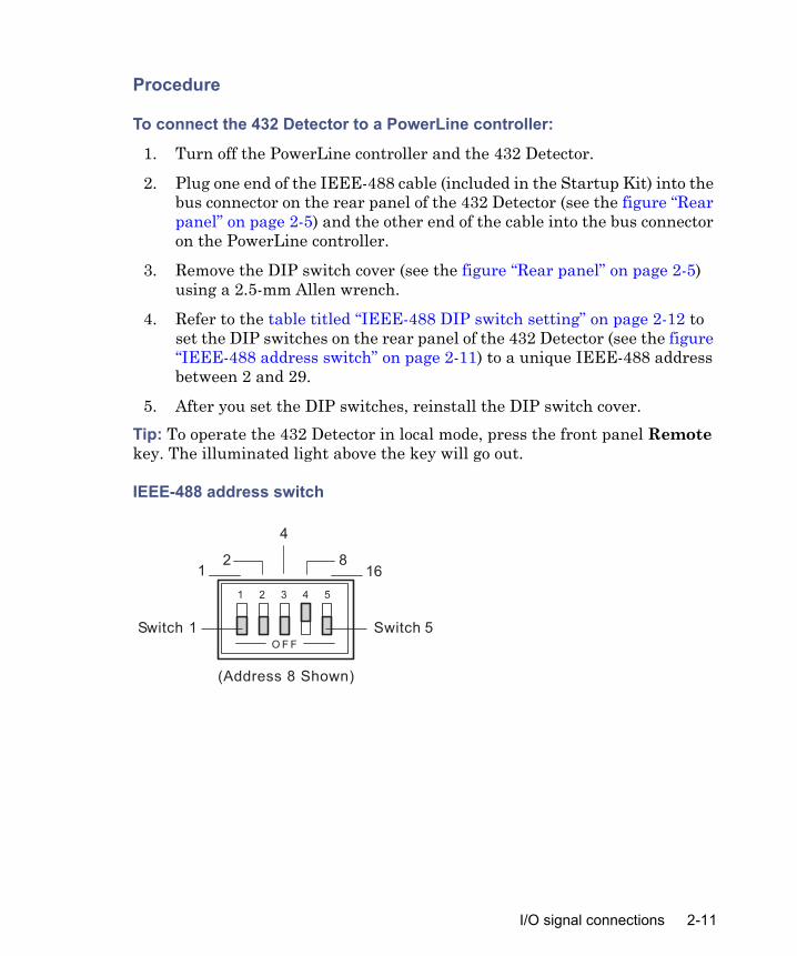
4. Refer to the table titled “IEEE-488 DIP switch setting” on page 2-12 to set the DIP switches on the rear panel of the 432 Detector (see the figure “IEEE-488 address switch” on page 2-11) to a unique IEEE-488 address between 2 and 29.
5. After you set the DIP switches, reinstall the DIP switch cover.Tip: To operate the 432 Detector in local mode, press the front panel Remote key. The illuminated light above the key will go out.
IEEE-488 address switch
1 2 3 4 5
O F F
12
4
816
Switch 5Switch 1
(Address 8 Shown)
I/O signal connections 2-11
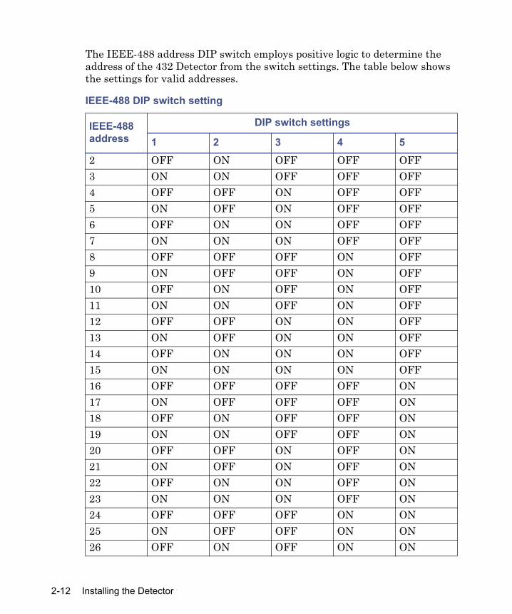
The IEEE-488 address DIP switch employs positive logic to determine the address of the 432 Detector from the switch settings. The table below shows the settings for valid addresses.
IEEE-488 DIP switch setting
IEEE-488 address
DIP switch settings
1 2 3 4 52 OFF ON OFF OFF OFF3 ON ON OFF OFF OFF4 OFF OFF ON OFF OFF5 ON OFF ON OFF OFF6 OFF ON ON OFF OFF7 ON ON ON OFF OFF8 OFF OFF OFF ON OFF9 ON OFF OFF ON OFF10 OFF ON OFF ON OFF11 ON ON OFF ON OFF12 OFF OFF ON ON OFF13 ON OFF ON ON OFF14 OFF ON ON ON OFF15 ON ON ON ON OFF16 OFF OFF OFF OFF ON17 ON OFF OFF OFF ON18 OFF ON OFF OFF ON19 ON ON OFF OFF ON20 OFF OFF ON OFF ON21 ON OFF ON OFF ON22 OFF ON ON OFF ON23 ON ON ON OFF ON24 OFF OFF OFF ON ON25 ON OFF OFF ON ON26 OFF ON OFF ON ON
2-12 Installing the Detector

PowerLine operation
Under PowerLine control, the 432 Detector is recognized as a 431 Detector and it retains the functionality of the 431 Detector with the following differences:
• The Balance field on the detector setup page of the PowerLine controller affects the Integrator Balance and the Integrator Output only.
• When you press the Setup key on the controller, the selected Balance value is sent to the 432 Detector from the PowerLine controller. However, the 432 Detector output does not change to the selected balance until the detector is autozeroed by a contact closure at the Auto Zero input terminals on the rear panel (remote or local mode) or when you press the Auto Zero key on the front panel (local mode only).
Under PowerLine control, the 432 Detector retains the full functionality of local mode operation, except for the following differences:
• The Recorder Sensitivity ranges of 0.0002 and 0.0001 are not accessible.• The Integrator Sensitivity ranges are not accessible.• The 432 Detector does not automatically perform an Auto Zero after an
Auto Base routine has occurred.
Empower and Millennium32 connectionsEmpower and Millennium32 software perform data acquisition, processing, and management of chromatographic information. This software requires the detector’s analog signal to be converted to a digital form.
27 ON ON OFF ON ON28 OFF OFF ON ON ON29 ON OFF ON ON ON
IEEE-488 DIP switch setting (Continued)
IEEE-488 address
DIP switch settings
1 2 3 4 5
I/O signal connections 2-13
Empower and Millennium32 are menu-driven applications specifically designed by Waters for chromatographers. Use the software to:
• Acquire data• Process data• Generate and print reports• Store information (or data) in a central area and share this information
with users who have proper security access
To connect the 432 Detector to an Empower or Millennium32 computer, be sure to:
• Connect the Bus Satellite Interface (SAT/IN) module to the Bus Laboratory Acquisition and Control/Environment (LAC/E™) card in the Empower computer, Millennium32 computer, acquisition client, or LAC/E32.
• Connect the 432 Detector to the Bus SAT/IN module (Channel 1 or 2).• Remove the IEEE-488 cable from the rear panel of the 432 Detector, if it
is connected.The 432 Detector is in local mode when it is connected to an Empower and Millennium32 computer.
Bus SAT/IN module
The Waters Bus SAT/IN module translates analog signals into digital form. It then transmits these digital signals to the Bus LAC/E card inside the workstation, acquisition client, or LAC/E32.
2-14 Installing the Detector
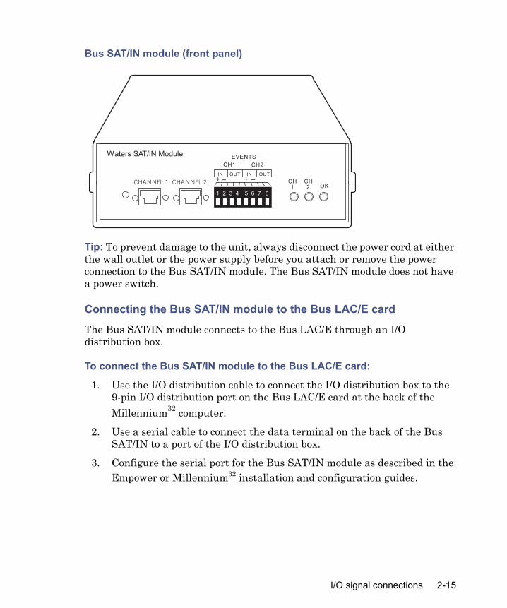
Bus SAT/IN module (front panel)
Tip: To prevent damage to the unit, always disconnect the power cord at either the wall outlet or the power supply before you attach or remove the power connection to the Bus SAT/IN module. The Bus SAT/IN module does not have a power switch.
Connecting the Bus SAT/IN module to the Bus LAC/E card
The Bus SAT/IN module connects to the Bus LAC/E through an I/O distribution box.
To connect the Bus SAT/IN module to the Bus LAC/E card:
1. Use the I/O distribution cable to connect the I/O distribution box to the 9-pin I/O distribution port on the Bus LAC/E card at the back of the Millennium32 computer.
2. Use a serial cable to connect the data terminal on the back of the Bus SAT/IN to a port of the I/O distribution box.
3. Configure the serial port for the Bus SAT/IN module as described in the Empower or Millennium32 installation and configuration guides.
1 2 3 4 5 6 7 8
CHANNEL 1 CHANNEL 2IN INOUT OUT
CH1
EVENTS
CH2
+ –
Waters SAT/IN Module
CH1
CH2 OK
+ –
I/O signal connections 2-15

Bus SAT/IN to Bus LAC/E connections
AC to DC Converter
I/O Distribution Por t (9-pin)of Bus LAC/E Card
I/O Distribution Box
Connect SAT/IN to Port 1 on theI/O Distribution Box
Modified ModularJack Connections
I/O Distribution Cable
PWRDATABCD
SAT/IN ModuleRear Panel
Serial Cable
2-16 Installing the Detector

Connecting the Bus SAT/IN module to the 432 Detector
The Bus SAT/IN module connects to the 432 Detector as shown below. Refer to the procedure following the figure and the table titled “Bus SAT/IN cable connections” on page 2-18 for complete details.
Bus SAT/IN to 432 Detector connections
To connect the 432 Detector to the Bus SAT/IN module:
1. Connect the white wire of the analog cable (included with the Bus SAT/IN module) to the Int + terminal on the rear panel of the 432 Detector. Connect the black wire to the Int – terminal.
Caution: To prevent damage to the unit, do not plug in the power cord of the Bus SAT/IN module until you perform all of the procedures described in the Waters Bus SAT/IN Module Installation Guide.
+
–
+
–
+
–
+
–
INT
REC
LEAK
MARKERIN
MARKEROUT
AUTO ZERO
TP01264
1 2 3 4 5 6 7 8
CHANNEL 1 CHANNEL 2
IN INOUT OUT
CH1
EVENTS
CH2
+ –
Waters SAT/IN Module
CH1
CH2 OK
Red
Black
Waters 432 Detector
+ –
I/O signal connections 2-17

2. Connect the other end of the cable to either the Channel 1 or Channel 2 connector on the front panel of the Bus SAT/IN module.
3. Connect the Event In terminals of the channel you chose in the previous step to the Inject Start output signal of the Waters Alliance® solvent delivery system or the Waters 717plus (or equivalent) Autosampler.
4. Remove the IEEE-488 cable from the rear panel of the 432 Detector, if it is connected.
The connections from the 432 Detector to the Bus SAT/IN are summarized below.
Data module connectionsThis section describes how to connect the analog output signal from the 432 Detector to the Waters 746 Data Module.
Bus SAT/IN cable connections
432 Detector I/Oconnector terminal Bus SAT/IN cable Bus SAT/IN connector
Int (+) White wireInt (–) Black wire Channel 1 or 2
Caution: Remember to meet the regulatory requirements of immunity from external electrical disturbances that may affect the performance of this instrument, do not use cables longer than 9.8 feet (3 meters) when connecting to the screw-type barrier terminal strips. In addition, ensure you always connect the shield of the cable to chassis ground.
2-18 Installing the Detector

Analog signal
To send the analog output signal from the 432 Detector to a Waters data module, connect the signal cable in the 432 Detector Startup Kit as described below.
Marker out signal
The Marker Out terminals of the 432 Detector provide a contact closure output signal when either of the following events occurs:
• Chart Mark key is pressed• Marker In terminals are shorted together
Use the signal to start a Waters 746 Data Module by connecting a signal cable to the module’s data cable.
Chart recorder connections
To connect the 432 Detector to a chart recorder:
1. Attach the Recorder cable (see Appendix C) to the 432 Detector REC output terminals, as indicated in the table titled “Chart recorder cable connections” on page 2-20.
Data module signal cable connections
Wire 432 Detector I/Oconnector terminal 746 terminal
Red Int (+) (+)Black Int (–) (–)Shield Ground lug None
Data module chart mark cable connection
Wire 432 Detector I/Oconnector terminal 746 cable
Either wire Marker Out Join to both Remote Start wires (white and red)
Other wire Marker Out Green wire
I/O signal connections 2-19

2. Connect the cable shield to the ground lug on the 432 Detector rear panel.
3. Connect the other end of the cable to the 10-mV input terminals on the chart recorder.
Chart marker input connectionsThe 432 Detector accepts a chart mark (start inject) signal from the following devices:
• Waters 717plus Autosampler• Any other device that provides a compatible switch closure
Waters 717plus Autosampler
To connect the 432 Detector to a Waters 717/717plus Autosampler, connect a signal cable as indicated in the table below.
Chart recorder cable connections
Wire 432 Detector I/Oconnector terminal
Chart recorder terminal
Red Rec (+) Pen (+)Black Rec (–) Pen (–)
Autosampler chart mark cable connections
432 Detector I/Oconnector terminal Autosampler terminal
Marker In (+) Either Inject Start terminal of a pairMarker In (–) Other Inject Start terminal of the same pair
2-20 Installing the Detector

Auto Zero input connectionsThe voltage at the Recorder and Integrator outputs is set to the user-selected balance offset level when a contact closure occurs between the Auto Zero terminals. This section describes how to connect the 432 Detector to the following devices (so that an auto zero occurs at the injection point):
• Waters 717plus Autosampler• Any other device that provides a compatible switch closure
Waters 717plus Autosampler
To connect the 432 Detector to a Waters 717plus Autosampler, connect a signal cable as indicated in the table below.
Alliance Separations Module connectionsConnect the detector to Waters Alliance Separations Modules, when it is not under the control of the Millennium32 software, to perform the following tasks:
• Auto-Zero on inject• Chart mark on inject• Method start
Generating Auto-Zero on inject
To generate the Auto-Zero function on the 432 Detector at the start of an injection, make the connections summarized in the table titled “Connections for generating Auto-Zero on inject” on page 2-22 and illustrated in the figure
Autosampler Auto Zero cable connections
432 Detector I/Oconnector terminal Autosampler terminal
Auto Zero (+) Either Inject Start terminal of a pairAuto Zero (–) Other Inject Start terminal of the same pair
I/O signal connections 2-21

“Alliance Separations Module connections to the 432 Detector Auto-Zero on inject” on page 2-22.
Before you can generate an Auto-Zero from an Alliance Separations Module, you must configure the Auto-Zero signal at the 432 Detector front panel. The default Auto-Zero signal is Low.
Alliance Separations Module connections to the 432 DetectorAuto-Zero on inject
Generating chart mark on inject
To generate the chart mark function at the start of an injection, make the connections summarized in the table below and illustrated in the figure
Connections for generating Auto-Zero on inject
Alliance Separations Modules (B inputs and outputs) 432 Detector (A inputs)
Pin 1 Inject Start Auto-Zero (+)Pin 2 Inject Start Auto-Zero (–)
Inject start +Inject start –GroundStop flow +Stop flow –Hold inject 1+Hold inject 1 –Hold inject 2 +Hold inject 2 –GroundChart out +Chart out –
Waters AllianceB (inputs and outputs)
10 Auto-Zero -9 Auto-Zero +8 Ground7 Chart Mark -6 Chart Mark +5 Lamp On/Off -4 Lamp On/Off +3 Ground2 Inject Start -1 Inject Start +
Waters 432 DetectorA (inputs)
+–+–
+–
+–
Int
Rec
Marker in
Auto Zero
Leak
Marker out
2-22 Installing the Detector

“Alliance Separations Module connections to the 432 Detector chart mark on inject” on page 2-23.
Before you can generate a chart mark from an Alliance Separations Module, you must configure the chart mark signal at the front panel. The default chart mark signal is Low.
Alliance Separations Module connections to the 432 Detectorchart mark on inject
Making fluidic connections
Fluid lines to a column and waste container connect to the front of the 432 Detector, as shown in the figure “Fluid connections” on page 2-24. To make these connections:
Connections for generating chart mark on inject
Alliance Separations Modules (B inputs and outputs) 432 Detector (A Inputs)
Pin 1 Inject Start Marker In (+)Pin 2 Inject Start Marker In (–)
Inject start +Inject start –GroundStop flow +Stop flow –Hold inject 1+Hold inject 1 –Hold inject 2 +Hold inject 2 –GroundChart out +Chart out –
Waters AllianceB (inputs and outputs)
10 Auto-Zero -9 Auto-Zero +8 Ground7 Chart Mark -6 Chart Mark +5 Lamp On/Off -4 Lamp On/Off +3 Ground2 Inject Start -1 Inject Start +
Waters 432 DetectorA (inputs)
+
–
+
–
+
–
+
–
INT
REC
LEAK
MARKERIN
MARKEROUT
AUTO ZERO
+–+–
+–
+–
Int
Rec
Marker in
Auto Zero
Leak
Marker out
Making fluidic connections 2-23

• Cut the tubing.• Assemble compression fittings and ferrules.• Connect the tubing to the detector.
This section will guide you through each of these procedures.
Fluid connections
Cutting stainless steel tubingYou need the following tools to cut stainless steel tubing:
• A file with cutting edge• Two cloth- or plastic-covered pliers
Caution: Conductivity detection is sensitive to flow rate fluctuations. If you use a non-Waters pump or a Waters pump without the SILK microflow compensation algorithm, you must install the pulse dampener kit supplied in the Startup Kit for optimum performance. Refer to the installation procedure in this section.
In From Column IN OUT
Out To Waste (18 inches.
0.009-inch I.D.)
Waters 432Conductivity Detector
Out to waste(18 inches, 0.000-inch ID)
In from column
2-24 Installing the Detector

To cut the tubing:
1. Measure the length of 1/16-inch OD, 0.009-inch ID, stainless steel tubing you need to make the following connections:• Column to the detector inlet• Detector outlet to a suitable waste container
2. Use a file with a cutting edge to scribe the circumference of the tubing at the desired length.
3. Grasp the tubing on both sides of the scribe mark with cloth-covered pliers. Gently work the tubing back and forth until it separates.
4. File the ends smooth.
Cutting polymeric tubingWaters chromatography systems are supplied with a tubing cutter (similar to the one in the figure “Cutting polymeric tubing” on page 2-26) to facilitate cutting polymeric tubing. This section presents the recommended procedure for using the tubing cutter.Tip: To avoid bandspreading caused by angled cuts, always use a tubing cutter. Angled cuts leave unswept dead volumes at the connection junction due to the poor fit of the tubing against the connector or port.
To cut a length of polymeric tubing:
1. Estimate the length of tubing required to connect the components. Allow slack so that the tubing is not pulled tightly around sharp corners.
2. Insert the tubing into the cutter so that the tubing extending from the metal side is the length required. Use the proper hole to have a snug enough fit so that the tubing is not flexed by the blade when you cut it.
Making fluidic connections 2-25
Cutting polymeric tubing
3. Press down on the razor blade to cut the tubing. Discard the excess tubing that extends from the clear side of the cutter.
4. Inspect the cut for burrs or scratches and for the perpendicularity of the cut.
Assembling compression fittings
To assemble each compression fitting:
1. Slide the compression screw over the tubing end, followed by the ferrule.
2. Mount the ferrule with its taper end facing the end of the tubing.
Ferrule and compression screw assembly
CompressionScrew
Ferrule
0.009-inch I.D. Tubing(0.23 mm)
Compression screwFerrule
0.0009-inch ID tubing(0.23 mm)
2-26 Installing the Detector
Connecting to the 432 Detector
To make connections at the column outlet and detector inlet, and at the detector outlet:
1. Install a compression screw and then a ferrule on the length of 0.009-inch tubing from the column outlet. Use stainless steel fittings on stainless steel tubing and PEEK fittings on PEEK tubing.Tip: If you are using a column with 1/4–28 end fittings and there is a length of tubing with 1/4–28 fittings on each end, use the 1/4–28 to Z-detail adapter (included in the Startup Kit) to connect this tubing to the tubing that leads to the detector inlet.The Waters IC-Pak C column comes supplied with a length of tubing that has a 1/4–28 fitting on one end (column outlet) and a Waters compression screw and ferrule on the other end (detector inlet).
2. Push the free end of the tubing as far as it will go into the IN fitting on the 432 Detector. While you hold it there, use a 5/16-inch open-end wrench to tighten the compression screw 3/4-turn past finger-tight.Tip: The 432 Detector and IC-Pak series of columns have very deep ferrules.
3. Remove the compression screw and tubing from the connection and verify that fluid can flow freely.
4. Reconnect the tubing to the IN fitting, making sure to push the tubing all the way into the fitting.
5. Install a ferrule on an 18-inch length of 0.009-inch tubing and connect it to the OUT connection on the 432 Detector. Use stainless steel fittings on stainless steel tubing and PEEK fittings on PEEK tubing.
6. Place the other end of the tube in a waste container. If you are using any Teflon tubing, attach it after the stainless steel or PEEK tubing.
Installing the pulse dampenerTo achieve the best performance from the 432 Detector in a chromatographic system with a non-Waters pump, Breeze™ software, or Waters HPLC 515 Pump, you must install the pulse dampener kit supplied in the Startup Kit. The pulse dampener is not required if you are using a Waters 2695 Separations Module.
Making fluidic connections 2-27

To install the pulse dampener between the pump and the injector:
1. Assemble the pulse dampener (see the figure “Pulse dampener” on page 2-28) using the instructions in the pulse dampener kit.
2. Connect the large-ID (0.020-inch) tubing to the pump outlet using a stainless steel compression screw and ferrule.
3. Connect the small-ID (0.009-inch) tubing to the injector inlet using a stainless steel compression screw and ferrule.
4. Disconnect the tubing from the injector inlet.
5. Pump ASTM Type I reagent water at £ 2 mL/min through the pulse dampener assembly until you see a constant stream exiting from the restrictor assembly outlet line.
6. Reconnect the tubing to the injector inlet.
Pulse dampener
Low Pressure FilterAssembly
Restrictor Assembly
0.020-inch I.D. Tubing
0.009 inch I.D. Tubing
To InjectorUnionFrom Pum p To injectorUnion
0.009-inch ID tubing0.020-inch ID tubing
From pump
Restrictorassembly
Low pressurefilter assembly
2-28 Installing the Detector
Passivating the system
Passivating the system removes potential contamination from the wetted surfaces of all system components. Perform passivation on a new system, and subsequently, whenever you suspect that contamination may have occurred. See “Troubleshooting” on page 5-6, for help diagnosing performance problems.Use this procedure for Waters hardware only. For other equipment, check with the manufacturer before you continue with this procedure.
To passivate the system:
1. Replace the column with a union fitting.
2. If the system is not new, flush it thoroughly with ASTM Type I reagent water to remove any residual solvents or salts.
3. Connect the power cord to the 432 Detector and plug the other end into an AC power outlet. Push the 432 Detector power switch to turn on the instrument.
4. Prime the pump with 6 N nitric acid (HNO3) and run it at a flow rate of 1.2 mL/min for 20 minutes to passivate all the wetted parts of the detector. Press the Clear key to stop the overrange alarm.
5. Stop the pump.
6. Remove the inlet line from the nitric acid and place it in ASTM Type I reagent water.
7. Flush the system using one of the following methods:• Prime and start the pump, then flush it with ASTM Type I reagent
water at 1.2 mL/min until you observe a consistent reading of less than 20 μS (base range set to 50 μS).
Caution: If you are installing the 432 Detector into an existing Waters system, replace the pump seals before you passivate. Use the new pump seals supplied in the Startup Kit and refer to the replacement procedure in the pump manual.
Warning: To avoid chemical hazards, always wear safety glasses and gloves when you are using solvents.
Passivating the system 2-29

• Flush the system overnight with 100% methanol at a reduced flow rate. By the next morning the system will be passivated and ready for use.
Tip: If you are using a pump with seal-wash capability, skip step 8.
8. Use a syringe to flush the back of the pump seals and pistons by slowly running about 5 mL of water into the top hole in the baseplate of the pump heads. Place a tissue under the baseplates to absorb the water.
9. Set the pump flow rate to 0.0 mL/min. It is not necessary to turn off the 432 Detector unless it will be idle for an extended period (14 days).
For best results, always leave the power on to maintain cell temperature; it takes a minimum of 2 to 3 hours once the detector is turned on to equilibrate the flow cell at the selected operating temperature.
Verifying the detector
This procedure is a guideline for verifying that the detector works correctly within its expected operational range. The detector is calibrated before shipping, and recalibration is not normally required.Verify the detector when any of these conditions apply:
• When you replace the flow cell• To verify accuracy• When you make adjustments
Calibration procedureTip: You need solution of 1 mM potassium chloride (KCl) to calibrate the detector.Tip: Waters suggests one of its Technical Service Representatives perform this procedure.
To perform the calibration procedure:
1. Turn on the 432 Detector and set the temperature control to 35 °C. Allow 2 to 3 hours for the temperature in the flow cell to equilibrate.
2. Set the base range to 200 μS.
3. Set the Filter Time Response to Fast.
2-30 Installing the Detector

4. Pump 1 mM KCl solution through the detector (without a column in place).
5. Verify that the front panel output is 147 μS ± 5 μS.
Verifying the detector 2-31

2-32 Installing the Detector

3 Operating the Detector
This chapter contains:• A description of front panel controls and displays• Procedures for starting up, shutting down, and long-term storage• Recommended operating practices
Contents
Topic PageControls and indicators 3-2Startup and shutdown 3-8Operating recommendations 3-9
3-1

Controls and indicators
The figure below illustrates the controls and indicators on the front panel of the 432 Detector.
Front panel
Power switchThe power switch (located in the lower-right corner of the front panel) controls power to the 432 Detector. Upon startup, an initialization routine verifies the data in ROM memory, tests RAM memory function, and checks for any internal leakage or an eluent conductivity over-range condition.
DisplayThe display shows instrument status and parameter values in two 20-character lines of text. Upon startup, Waters 432 Self Check appears
Remote Temp. Pol. ChartMark
7 8 9
4 5 6
1 2 3
0 . Clear
EnterShift
Resp. Bal.
BaseRange
Sens.Range
AutoBase
AutoZero
CONDUCT( S/cm)
BASE( S/cm/FS)
SENS
274 500 0.0005
ON
OFFIN OUT
Waters 432Conductivity Detector
3-2 Operating the Detector

briefly. If any error conditions are detected during startup or normal operation, the appropriate error message is displayed.The main screen shows the measured conductivity, as well as the base range and sensitivity settings. When you set an operating parameter, the display shows the selected or entered value.
Error messages
A corresponding error message is displayed if one of the following conditions occurs:
• ROM/RAM error (checked during startup only)Error: ROM/RAM
• Leakage detectedError: Leak
• Temperature control failureError: Temp
• Over-range (above base range setting)Error: Over Range
• Overflow (above 10,000 μS)Error: Over Flow
Press the Clear key to clear an error alarm and message. For a continuing error condition, the error message remains after the audio alarm is cleared.
KeypadUse the keypad to control the operation of the 432 Detector. The table titled “Key descriptions” on page 3-4 describes the function of each key.
Controls and indicators 3-3

Tip: Three keys (Balance, Sensitivity Range, and the numeral 1) perform an alternate function when they are preceded by the Shift key.
Key descriptions
Key FunctionRemote key: Toggles between local and remote operating modes. In remote mode, the light above the key is on and all other front panel controls are disabled.
Polarity key: Toggles the polarity of the signal to the external chart recorder and integrator. When positive polarity is selected, the light above the key is illuminated.
Base Range key: Sets the base sensitivity range of the 432 Detector to the appropriate value for the eluent being used. The base sensitivity is set to one of ten steps, from 10 μS (maximum gain) to 10,000 μS, using the Up and Down keys or the numeric keypad.Sensitivity Range key: Sets the sensitivity range multiplier of the 432 Detector. The sensitivity range has twelve steps, from 0.0001 (maximum sensitivity) to 1.0 (available only with 100 μS multiplier setting), and is set using the Up and Down keys or the numeric keypad. The 10-mV full-scale recorder response is calculated by multiplying the Base Range by the Sensitivity Range to obtain a value of “x” μS / 10 mV FS. The recorder range is 1 to 0.0001 for the 100 μS setting and 0.1 to 0.0001 for the two lower settings.
Shift key then Sensitivity Range key: Sets the sensitivity range multiplier of the integrator to 100, 50, or 10 μS using the Up and Down keys or the numeric keypad; the integrator output is 100, 50, or 10 μS/1 V, respectively.
Remote
Pol.
Base Range
Sens.Range
3-4 Operating the Detector

Balance key: Manually sets the offset (%) of the signal to the external chart recorder. (Use the numeric keypad or Up and Down keys.)
Shift key then Balance key: Manually sets the offset (%) of the signal to the integrator. (Use the numeric keypad or Up and Down keys.)
Shift key after Balance key: Changes the polarity of the offset. Allowable values are –100 to +100%.Temperature key: Sets the temperature of the detection cell. Use the Up and Down keys or the numeric keypad to turn temperature control off (Setting 0) or select one of the following eight settings: 30, 35, 40, 45, 50, 55, 60, or 65 °C. The light above the key is illuminated when the temperature control is on.Response key: Sets the response time constant of the 432 Detector to optimize signal-to-noise ratio. Use the Up and Down keys or the numeric keypad to choose Setting 1 (Fast, 0.25 sec) for very narrow peaks, Setting 2 (Standard, 0.5 sec), or Setting 3 (Slow, 1.0 sec) to detect wider peaks. Setting 2 is used for most applications.Auto Zero key: Automatically zeros the Recorder and Integrator signals to the specified Recorder Balance and Integrator Balance offsets, respectively.
Auto Base key: Automatically sets the base range of the 432 Detector to the appropriate value for the eluent being used. This is the next highest setting above the actual background conductivity of the eluent.
Key descriptions (Continued)
Key Function
Bal.
Temp.
Resp.
AutoZero
AutoBase
Controls and indicators 3-5

Shift key: Press the Shift key before, not along with, other keys to access additional functions and also to change polarity when you set balance offset values. When the Shift key is pressed, an asterisk (*) appears at the right side of the display; press Shift again to return to normal mode.Shift key then Balance key: Displays the integrator balance offset value. When setting the balance offset, press Shift to change polarity.
Shift key then Sensitivity Range key: Displays integrator range value.
Shift key then 1 key: Displays the current, actual value of the chart recorder balance offset. Press Enter to return to the main screen.Chart Mark key: When this key is pressed, a 1-second, 1-mV signal is sent to the Recorder terminals and a 1-second contact closure is sent to the Marker Out terminals.
Enter key: When you manually set offsets, sensitivity range, or base range, pressing Enter records the displayed value and returns the display to the main screen. The Enter key is also used to access the beep setting function.Clear key: Erases a value input from the keypad. The Clear key is also used to clear an error alarm and message. For a continuing error condition, the error message remains after the audio alarm is cleared.
Up key: Increments the current parameter setting.
Key descriptions (Continued)
Key Function
Shift
ChartMark
Enter
Clear
3-6 Operating the Detector

Beep functionYou can set the 432 Detector to beep when a key is pressed and/or an error condition is detected.Use the Clear key to stop an error alarm. For a continuing error condition, the error message remains after the beep is cleared.To set the beep function, follow the procedure in the table below.
Tip: Since the void volume in many separations contains highly conductive counter-ions, the error alarm sounds upon each injection. See the table titled “Setting the beep function” on page 3-7 to silence the beep-on-error alarm.
Down key: Decrements the current parameter setting.
Setting the beep function
Keystroke Key Function1 Enter Accesses the beep function parameters.2 . (decimal point)3 Enter4 1 Turns on the beep-on-error function.
0 Turns off the beep-on-error function.5 1 Turns on the beep-on-keystroke function.
0 Turns off the beep-on-keystroke function.6 Enter Saves settings and returns to the main
screen.
Key descriptions (Continued)
Key Function
Controls and indicators 3-7

Startup and shutdown
Startup procedurePerform the following procedure to start the 432 Detector. Typically, this procedure is done at the beginning of each workday.Tip: This procedure assumes that the flow cell has stabilized at the selected temperature (minimum 2 to 3 hours). Standard practice is to leave the detector powered and with the temperature control on unless the instrument will be unused for several days.Set the temperature at least 5 °C above the highest ambient temperature expected for the duration of the application.
1. Prime the pump with properly degassed eluent and set the flow rate to 1.2 mL/min or to the flow rate recommended for your particular column or application. Do not sparge eluents, since sparge gasses may contain ionic contaminants.
2. Set the response (time constant) to the desired setting by pressing the Response key. A standard setting (0.5 seconds) is preferred for most applications.
3. Set the base value by pressing the Auto Base key or by manually entering the base range that is the next highest setting above the eluent’s background conductivity.
4. Turn on the recorder/integrator and run the system until the baseline stabilizes.
5. Depending on whether you are using a recorder or an integrator, do one of the following actions:• If you are using a 10-mV recorder connected to the Recorder
terminals on the rear panel, select the desired sensitivity by pressing the Sensitivity Range key, then the appropriate Up or Down arrow key.
• If you are using an integrator connected to the Integrator terminals on the rear panel, select the desired sensitivity by pressing the Shift and Sensitivity Range keys, then the appropriate Up or Down arrow key.
3-8 Operating the Detector

6. Zero the recorder/integrator by pressing the Auto Zero key or have the Auto Zero terminals of the rear panel I/O terminal strip connected to your manual injector or autosampler.
The 432 Detector is now ready for operation.
Standby setupTo eliminate the need to allow time for the flow cell temperature to equilibrate, leave the 432 Detector turned on at the end of the workday or workweek. Set the temperature control to the operating temperature and the pump flow rate to 0.01 to 0.1 mL/min (depending on the pump).
Long-term storageIf the 432 Detector is to be removed from a system for storage or if the system itself is to be stored for a long time, flush the detector/system with 100% water, then 100% HPLC-grade methanol. Leave the methanol in the system after shutdown. If you are removing the 432 Detector from the system, seal the inlet and outlet bulkheads with dead-end fittings or a loop of tubing.
Operating recommendations
Observe the following recommendations for best detector performance.
Temperature equilibrationThe 432 Detector should be powered up and set at the desired operating temperature for two to three hours before use. Select a temperature at least 5 °C above the highest ambient temperature expected during the duration of the application. The detector is usually set at 35 °C, but it should be set higher if the ambient temperature will exceed 30 °C.You may choose to leave the 432 Detector powered up overnight at a flow rate of 0.01– 0.1 mL/min (depending on the pump) to minimize the daily reequilibration time.A drifting baseline is one indication that the temperature of the flow cell is not uniform across the flow cell or stable over time.
Operating recommendations 3-9
Base rangeThe Base Range is normally set at the next setting above the background conductivity of the eluent. For example, if the conductivity of borate/gluconate eluent is 270 μS, set the Base Range to 500 μS.
Integrator outputThe Integrator output is not attenuated; signals should be below 1 V. Set the Integrator output to 10 μS/V for small signals or to 50 μS/V when you expect a signal greater than 10 μS. If you are using the 432 Detector with chemical suppression, set the integrator output to 100 μS/V.
Recorder outputThe Recorder output is attenuated and the Sensitivity Range should be adjusted to provide the appropriate output level.
PolaritySignal polarity depends on eluent conductivity. If necessary, press the Polarity key to obtain peaks rather than dips.
Eluent handlingReplace your eluent reservoir filter regularly. When you analyze cations, use an all-plastic eluent reservoir filter. Filter and degas eluents to prolong column life, reduce pressure fluctuations, and decrease baseline noise. When you change eluents, flush the flow cell and associated tubing thoroughly with the new eluent.
3-10 Operating the Detector

4 Performing Ion Analysis
This chapter provides essential information about ion analysis techniques. Two representative columns serve as typical examples: the Waters IC-Pak A for anions and the IC Pak C M/D for cations. The following topics are discussed:• Fundamental considerations• Configuring the system• Selecting and preparing eluents• Preparing and injecting standardsAlso refer to the manufacturer’s manual for the particular column you are using. A recommended source for more information about ion analysis in general is Ion Chromatography: Principles and Applications by Paul R. Haddad and Peter E. Jackson, Elsevier Science Publishing, New York, 1990.Contents
Topic PageFundamental considerations 4-2Configuring the system 4-5Eluents for ion analysis 4-6Standards for ion analysis 4-8
4-1

Fundamental considerations
To obtain full performance from the 432 Detector in chromatographic applications, observe the guidelines presented in this section regarding:
• Water• Containers• High-pH eluents• Sample preparation
WaterWater purity (the absence of conductivity) is the most important consideration in ion analysis.Tip: Using water other than ASTM Type I reagent water will compromise the accuracy of your results.Freshly drawn ASTM Type I reagent water, conforming to ASTM specification D1193, with total organic carbon <100 ppb is recommended. Sophisticated laboratory water systems that use a combination of reverse osmosis, mixed bed ion exchange, and carbon adsorption cartridges produce ASTM Type I reagent water, and are recommended for ion chromatography applications. Do not use HPLC-grade water or distilled water.
ContainersUse plastic to contain all anion and cation samples, cation standards, and cation eluents. When you analyze trace level ions in water, polystyrene containers such as tissue culture flasks are recommended; polypropylene or polymethylpentene containers suit most other applications. Use polystyrene tissue culture flasks for long-term storage.If your system operates on Breeze software or contains a 2695 Separations Module, use 4-mL polycarbonate vials to hold your samples and standards.
Caution: To avoid damage to the detector flow cell, do not allow the flow cell to dry out.
Caution: Avoid glass containers (which tend to leach sodium cations) when you are analyzing for cations.
4-2 Performing Ion Analysis

Preparing containers for low-level analysis
To prepare plastic containers for low-level analysis:
1. Soak all containers for 5 hours with a 1:1 solution of nitric acid (HNO3) and ASTM Type I reagent water.
2. Rinse with plenty of ASTM Type I reagent water. The containers are ready for analysis in the ppm range.
3. For analysis in the ppb range, fill each container completely with ASTM Type I reagent water and let soak overnight.
Certain applications that involve ppb level analysis may require container considerations beyond the scope of this manual. For further instructions on trace metal cleaning of plasticware, see “Selection and Cleaning of Plastic Containers for Storage of Trace Element Samples,” JR Moody and RM Lindstrom, Analytical Chemistry, v. 49, Dec 1977, pp. 2264-67, or contact the Waters Technical Services Department.
Cleaning syringes
To avoid contamination, always rinse a syringe two to three times with ASTM Type I reagent water before you draw standards or samples for injection.
High-pH eluentsHigh-pH eluents (such as hydroxide eluent) absorb atmospheric CO2, which slowly acidifies the eluent causing baseline drift and retention time changes.
To minimize carbonate absorption, connect a soda lime (Ascarite®) tube to the eluent bottle as follows:
1. Insert a 3/4-inch (2-cm) piece of glass wool in one end of a polyethylene tube with end fittings. Attach the end fitting.
2. Fill the tube with soda lime (Ascarite) until it reaches 3/4 inches (2 cm) from the top.
3. Add another piece of glass wool to the other end of the tube and attach the end fitting.
Warning: To avoid chemical burns, wear gloves, lab coat, and eye glasses when you are handling soda lime.
Fundamental considerations 4-3

4. Drill a hole in the cap of the reagent bottle. The hole should be large enough to accommodate the end fitting. Drill a second hole for the pump inlet line.
5. Pass the pump inlet line through the hole. Seal the hole with paraffin film.
6. Change the soda lime in the tube when it is exhausted.
Soda lime tube
End Fittings
Glass Wool
Soda Lime
Polypropylene Tube
Reagent Bottle
Pump Inlet Line
Glass wool
Soda lime
Polypropylene tube
Pump inlet line
Reagent bottle
End fittings
4-4 Performing Ion Analysis
Sample preparationSample preparation is very important in ion analysis. Contact the Waters Technical Services Department, if you need assistance.As a general rule, to analyze a sample of completely unknown ionic concentration, initially prepare at least a 1:100 dilution and inject 100 μL. For best results, injections should contain a total anion concentration of no more than 300 ppm for the IC-Pak A column or a total cation concentration of no more than 10 ppm per ion for the IC-Pak C M/D column.The sample volume (usually 100 μL) generally equilibrates to the pH of the eluent upon injection. However, for samples with pH values that differ greatly from that of the eluent (for example, strong acids and bases), bring the sample pH close to that of the eluent before you inject the sample, if possible.Do not inject concentrated samples directly into the mobile phase. Direct injection may cause precipitation of the salts in the sample. Dissolve (or dilute) samples in an appropriate volume of the mobile phase first. If you must use other solvents, watch for precipitation upon injection into the eluent. Always filter samples before you use them.Cationic samples that contain organic amines may exhibit hydrophobic interaction between the mobile phase and packing. You may use a water-miscible organic mobile phase, such as acetonitrile, as a modifier to reduce this. Pretreat the sample with a Sep-Pak® C18 cartridge to remove hydrophobic compounds.
Configuring the system
The figure “System configuration for ion analysis” on page 4-6 shows a typical system configuration. Refer to “Making fluidic connections” on page 2-23, for the procedures to cut tubing and assemble fittings.
Configuring the system 4-5

System configuration for ion analysis
Pulse dampenerIf your system uses a non-Waters pump or a Waters pump with Breeze software, such as the HPLC 515, use a pulse dampener (supplied in the Startup Kit) to achieve the best performance from the 432 Detector.Install the pulse dampener between the pump and the injector, as described in “Installing the pulse dampener” on page 2-27.
Eluents for ion analysis
This section describes how to select, prepare, and use eluents for ion analysis.
General guidelines
Observe the following guidelines when you prepare eluents for ion analysis:• Use only ASTM Type I reagent water with total organic carbon
<100 ppb.• Use the highest purity salts and reagents available.
Caution: Never recirculate eluents. Ions from sample and standard injections progressively contaminate a recirculating eluent.
TP01269
EluentReservoir
Pulse Dampener†
Pump
Injector
† Required for Waters pumps without SILK or non-W aters pumps
Guard Column Holder*
Column
Waters 432
Detector ToWaste
*Optional
Waters In-Line Degasser*Waters in-line degasser*
Eluentreservoir
*Optional
Towaste
Waters432
DetectorColumn
Injector
Pump
Guard columnholder*
Pulsedampener
t
tRequired for non-Waters pumps or Waters pumps with Breeze software, such as the HPLC 515
4-6 Performing Ion Analysis
• A pH meter is recommended for checking the pH of eluents; care should be taken to avoid cross contamination. Adjust the pH with potassium hydroxide (KOH) or lithium hydroxide (LiOH). For eluents such as octane sulfonate, test an aliquot of the eluent with pH paper. Never immerse pH paper directly into a batch of eluent.
• Use the following formula to prepare eluents:Formula Wt of Salt x Molarity = g/L Salt
Eluent filtering and degassing
The Waters Solvent Clarification Kit is recommended for eluent filtration and preliminary degassing. Durapore® 0.22-mm filters can be used for all ion chromatography eluents. Millipore 0.45-mm HATF filters may be used for aqueous eluents containing no organic modifier. For eluents containing organic modifier, use the Durapore filters.
After you install a new filter, pass 20 to 30 mL of eluent through the filter under vacuum. Turn off the vacuum, swirl the eluent throughout the flask and discard. Reattach the flask to the filter apparatus and filter the remaining eluent. As soon as filtration is complete, transfer the eluent to a precleaned plastic container, introducing the least possible amount of bubbles in the process.The Waters In-line Degasser is recommended for continuous online degassing.
Preparing anion eluentThis section presents the procedure for the preparation of sodium borate/gluconate concentrate and eluent.Consult the manufacturer’s manual for your column (IC-Pak Column and Guard Column Care and Use Manual included with Waters columns) for additional instructions on the selection and preparation of eluents.A recommended source for more information about ion analysis in general is “Ion Chromatography: Principles and Applications,” by Paul R. Haddad and Peter E. Jackson, Elsevier Science Publishing, New York, 1990.
Caution: To avoid contamination when you analyze for cations, minimize the time that the eluent is in contact with the glass filtration apparatus and transfer the eluent to a suitable pre-cleaned plastic container as soon as possible.
Eluents for ion analysis 4-7

Preparing lithium borate/gluconate concentrate
To prepare sodium borate/gluconate concentrate, refer to “Preparing lithium borate/gluconate 50X stock concentrate” on page D-13 and “Preparing lithium borate/gluconate eluent” on page D-14.
Preparing cation eluentTo prepare 1 L of cation eluent, refer to “Preparing eluent” on page D-3.
Standards for ion analysis
This section describes how to prepare and inject ion standards.Tip: It is recommended to purchase certified 1000-ppm anion standards instead of preparing them manually. Certify all manual standards against National Institute of Science and Technology traceable standards.Standard concentrations in this manual are defined in terms of mass. For example, 1 mg of sample per liter of water equals a 1 ppm concentration, since 1 L of water has a nominal mass of 1 kg (0.997 kg at 25 °C).1 part per thousand = 1 mg/mL = 1 g/L = 1000 ppm1 part per million (ppm) = 1 μg/mL = 1 mg/L = 1000 ppb1 part per billion (ppb) = 1 ng/mL = 1 μg/L = 1000 ppt1 part per trillion (ppt) = 1 pg/mL = 1 ng/L
Storing standards
For accurate quantitative results, do not store standards beyond the approximate periods listed in the table below. Be aware that shelf-life depends on many factors and may be significantly shorter than shown here.
Shelf-life of standards
Standard Shelf-lifeCarbonate, ppm 1 dayChloride, ppm 3 weeksAll, ppb 1 dayNitrite and carbonate concentrates 1 week
4-8 Performing Ion Analysis

Cation standards must be stored in properly prepared plasticware. See “Containers” on page 4-2.
Preparing anion standardsThis section presents the procedure for preparing a 7-anion standard. If a simpler standard suffices, follow the procedure, but select only three or four salts, such as sodium chloride, sodium nitrate, and sodium sulfate.Always use salts of at least reagent-grade purity. If you require quantitative results or you use hygroscopic salts, dry the salts overnight at 80 °C before you make solutions. Store the dried salts in a desiccator.
Preparing a 7-anion standard
To prepare a 7-anion standard:
1. Weigh out the amounts of dry salts shown in the table below or use the following formula to calculate the amount for a salt not listed:(Mol. Wt. Salt / Mol. Wt. Cation) x 0.1 = g Salt
All other anion concentrates 1 to 2 monthsCation standards 1 monthCation concentrates 6 months
Salts for anion standard concentrates
Salt (anion) Weight (mg)
Sodium fluoride (F–) 221.0 Sodium chloride (Cl–) 164.9 Sodium nitrite (NO2
–) 150.0 Potassium bromide (Br–) 148.9 Sodium nitrate (NO3
–) 137.1 Potassium phosphate, monobasic (HPO4
2–)141.8
Sodium sulfate (SO42–) 147.9
Shelf-life of standards (Continued)
Standard Shelf-life
Standards for ion analysis 4-9

2. Place each salt in a separate plastic100-mL volumetric flask and dilute to the mark with ASTM Type I reagent water. Each concentrate contains 1000 ppm of the anion.
3. Combine the amounts listed in the table below in a 100-mL volumetric flask with ASTM Type I reagent water.
Injecting anion standards
Required materials
To inject a standard, obtain the following materials:• Borate/gluconate eluent – Refer to “Preparing lithium
borate/gluconate 50X stock concentrate” on page D-13 and “Preparing lithium borate/gluconate eluent” on page D-14.
• 1-cc disposable plastic syringe – Pharmaseal® Stylex® disposable syringe with a Luer Slip® tip, or equivalent.
• Autoinjector or manual injector with 100-μL loop – Ion chromatography commonly uses a 100-μL injection volume. When you use a fixed loop, overfill a minimum of three times.
Anion concentrate dilutions
Anion Amount (μL) Final Concentration (ppm)
Fluoride 100 μL 1 ppmChloride 200 μL 2 ppmNitrite 400 μL 4 ppmBromide 400 μL 4 ppmNitrate 400 μL 4 ppmPhosphate 600 μL 6 ppmSulfate 400 μL 4 ppm
4-10 Performing Ion Analysis

Injecting the standard
To inject the standard:
1. Set up the 432 Detector as follows:• Base Sensitivity = 500 μS• Integrator Sensitivity = 10 μS/V• Recorder Sensitivity = 0.01 (strip chart)• Response = STD (0.5 seconds)• Temperature = 35 °C• Polarity = +
2. Equilibrate the 432 Detector as described in “Startup procedure” on page 3-8.
3. Rinse a 1-cc disposable plastic syringe two or three times with ASTM Type I reagent water, then load the standard.
4. Place the syringe tip into the sample loading port and overfill the 100 μL loop at least three times (that is, 300 μL).
5. Inject the sample.The figure “Chromatogram of a 7-anion standard” on page 4-12 shows a representative chromatogram of the 7-anion standard run on an IC-Pak A (4.6 mm x 5.0 cm) column with borate/gluconate eluent at 1.2 mL/min flow rate. The separation of the standard typically takes 12 to 15 minutes with this setup.
Standards for ion analysis 4-11

Chromatogram of a 7-anion standard
Preparing cation standardsThis section presents the procedure for preparing an 8-cation standard. If a simpler standard suffices, follow this procedure selecting only those salts that you want in the standard. For accurate quantitative results, use only properly prepared plasticware and do not store standards beyond the recommended shelf-lives listed in the table titled “Shelf-life of standards” on page 4-8.
Preparing cation standard concentrates
Tip: It is recommended that you use certified 1000-ppm cation standards not prepared in acid with this method.
4-12 Performing Ion Analysis

To prepare concentrated stock solutions for an 8-cation standard (prepare fewer types of cations, if a simpler standard suffices):
1. Weigh out the amounts of dry salts shown in the table titled “Salts for cation standard concentrates” on page 4-13 or use the following formula to calculate the amount for a salt not listed.(Mol. Wt. Salt / Mol. Wt. Cation) = g SaltIf you choose to use other salts, be sure to avoid any combinations that will form a precipitate.
2. Place each salt in a separate plastic1-L volumetric flask and dilute to the mark with reagent-grade water. Each concentrate contains 1000 ppm of the cation.
Salts for cation standard concentrates
Salt (cation) Weight (g)
Lithium hydroxide monohydrate (Li+) 6.0476
Sodium chloride (Na+) 2.5421
Ammonium chloride (NH4+) 2.9640
Potassium chloride (K+) 1.9067
Magnesium nitrate hexahydrate (Mg2+) 10.5466Calcium nitrate tetrahydrate (Ca2+) 5.8919Strontium nitrate tetrahydrate (Sr2+) 3.2377Barium chloride dihydrate (Ba2+) 1.7786
Standards for ion analysis 4-13

Preparing an 8-cation standard
To prepare 1 liter of 8-cation standard:
1. Add the volume of stock (concentrate) standard listed in the table below to a plastic 1-L volumetric flask.
2. Fill the flask to the mark with ASTM Type I reagent water.
Injecting cation standards
Required materialsTo inject the standard, obtain the following materials:
• 0.1 mM EDTA/ 3 mM HNO3 cation eluent – Refer to “Preparing cation eluent” on page 4-8.
• 1-cc disposable plastic syringe – Pharmaseal® Stylex® disposable syringe with a Luer Slip® tip, or equivalent.
• Injector or autosampler with a 100-μL loop – Ion chromatography commonly uses a 100-μL injection volume. When you use a fixed loop, overfill a minimum of three times.
Cation concentrate dilutions
Cation Amount (mL) Final concentration (ppm)Lithium 0.25 0.25Sodium 1.00 1.00Ammonium 1.00 1.00Potassium 3.00 3.00Magnesium 2.00 2.00Calcium 3.00 3.00Strontium 5.00 5.00Barium 5.00 5.00
4-14 Performing Ion Analysis

Injecting the standardTip: You can substitute the method described in “Alkali and alkaline earth cations, ammonium, and amines” on page D-15, for the following procedure.
To inject the standard.
1. Set up the 432 Detector as follows:• Base Sensitivity = 2000 μS• Integrator Sensitivity = 50 μS/V• Recorder Sensitivity = 0.01 (strip chart)• Response = STD (0.5 seconds)• Temperature = 35 °C• Polarity = – (negative)
2. Equilibrate the 432 Detector as described in “Startup procedure” on page 3-8.
3. Rinse a 1-cc disposable plastic syringe two or three times with ASTM Type I reagent water, then load the standard.
4. Place the syringe tip into the sample loading port and overfill the 100-μL loop at least three times (that is, 300 μL).
5. Inject the sample.The figure “Chromatogram of an 8-cation standard” on page 4-16 shows a representative chromatogram of an 8-cation standard run on an IC-Pak C M/D column with 0.1 mM EDTA/3 mM HNO3 eluent at 1.0 mL/min flow rate. The separation of the standard typically takes 20 to 25 minutes with this setup.
Standards for ion analysis 4-15

Chromatogram of an 8-cation standard
4-16 Performing Ion Analysis

5 Maintenance
This chapter contains information about maintaining the 432 Detector and troubleshooting charts to help you isolate and correct problems..
Warning: To avoid the possibility of electric shock, power off the detector and disconnect the power cord before you service the instrument.
Contents
Topic PageRoutine maintenance 5-2Cleaning the detector exterior 5-6Troubleshooting 5-6
5-1
Routine maintenance
This section contains information designed to help you maintain the 432 Detector. Routine maintenance for the 432 Detector includes:
• Replacing the fuse• Calibrating the detector• Maintaining the flow cell
Waters service specialists provide maintenance for the 432 Detector on a corrective, as required, basis. Contact the Waters Technical Services Department if you have questions regarding the repair or performance of your instrument.Follow these suggestions to help you maintain the 432 Detector:
• Stock the recommended spare parts listed in Appendix B to reduce downtime. Contact the Waters Service Department for assistance.
• Record the initial installation date and serial number of your instrument in Appendix C for easy reference.
• Keep a file of typical chromatograms for comparison when you suspect problems.
Replacing the fuse
To change the operating voltage fuse:
1. Turn off the front panel power switch and remove the power cord from its connector on the rear panel of the detector.
2. Pry open the power connector cover with a screwdriver.
3. To change the AC power fuses, pull out each fuse holder as though opening a drawer. Spare fuses are included in the System Startup Kit. For ordering information, see Appendix C.
4. The table titled “Nominal operating voltage” on page 2-6 lists the operating voltage fuses (for use in either North America or Europe).
Warning: To avoid the possibility of electric shock, turn off the front panel power switch, and unplug the power cord from the rear panel.
5-2 Maintenance

5. Install the correct fuse in the holder and slide it back into place. The arrow on each fuse holder points up when in the correct position.
Installing operating voltage fuses
6. Close the power connector cover. Then plug the power cord into its connector on the rear panel of the detector.
Maintaining the flow cellMaintenance for the 432 Detector consists of ensuring the flow cell is free of foreign material. Foreign material in the flow cell may cause baseline drift, cycling, or noise.
To clean the cell:
1. Flush the system with ASTM Type I reagent water.
2. Flush the system with 20 mL of 6 N nitric acid (HNO3).
3. Flush the system again with ASTM Type I reagent water. Do not reconnect the column until the eluent has returned to about pH 7.
Caution: To avoid damaging the column, remove it before you flush the system. Do not reconnect the column until the eluent has returned to approximately pH 7.
Routine maintenance 5-3

Refer to Appendix C, to order a replacement flow cell. The following tools are required to replace the flow cell:
• Phillips-head screwdriver• 5/16-inch open-end wrench• Knife or flat-blade screwdriver
To replace the flow cell:
1. Unplug the 432 Detector from the power source, and completely disconnect all electrical cables and fluid connections.
2. Remove the 432 Detector cover (four Phillips-head screws, two on each side).
3. Remove the two pins and pin holders that hold the cell block cover in place (see figure “Flow cell assembly” on page 5-5). Use a knife or flat-blade screwdriver to gently pry the pins and holders out.
4. Pull off the cover of the flow cell unit and remove the top layer of insulation.
5. Remove the four Phillips-head screws from the upper plate of the cell block, and remove the plate. Note the orientation of the plate: a notch is cut into the underside to clear one of the components within the cell block.
6. Carefully disconnect the inlet and outlet fittings from the flow cell.
7. Remove the two Phillips-head screws from the flow cell mounting bracket.
8. Unplug the flow cell cable connector from its socket in the cell block.
9. Remove the flow cell assembly.
10. Install the new flow cell by following steps 2 through 9 in reverse order. Be sure to orient the upper plate of the cell block properly before you install the four screws.
Warning: To avoid electrical hazards, always unplug the power cord before you perform any of the following replacement procedures.
5-4 Maintenance

Flow cell assembly
Pin
Upper plate screws
Upper plate cell block
Insulation
Cell block cover
Pin
ConnectorFlow cell
Cell mounting bracket screws
Cell mountingbracket
Cell block
Pin holder
Pin holder
Cell block cover
Pin
Pin holder
Pin holder
Pin
Insulation
Upper platescrews
Upper plateof cell block
Cell mountingbracket screws
Cell mountingbracket
Flow cellConnector
Cell block
Routine maintenance 5-5
Cleaning the detector exterior
To clean the outside of the 432 Detector, use only a soft lint-free paper or cloth dampened with mild soap and water.
Troubleshooting
This section contains troubleshooting charts to help you isolate and correct problems with the 432 Detector.Keep in mind that the source of apparent detector problems may lie within the chromatography or hardware of your system. The Waters Guide to Successful Operation of Your LC System contains detailed chromatographic troubleshooting tables. (Contact your nearest Waters office for information on how to get a copy.) If you cannot correct a problem, contact the Waters Technical Services Department for assistance.
When you call Waters serviceTo expedite your request for service, have the following information available when you call Waters regarding a 432 Detector problem:
• Symptom• Type of column• Eluent(s)• Flow rate• Operating pressure• Base Range setting• Integrator Sensitivity setting• Recorder Sensitivity setting• Type of injector (automatic or manual)• Type of data integrator
Detector does not turn onIf your detector is completely inoperative (for example, the lights do not illuminate and the display remains completely blank when the unit is turned
5-6 Maintenance

on), the fuse may require replacement. Refer to “Replacing the fuse” on page 5-2.
Startup diagnosticsThe 432 Detector performs startup diagnostics that check the internal memory (both RAM and ROM), and the associated processing circuitry.
Power supplyThe following factors can adversely affect the operation of the 432 Detector:
• Power surges• Line spikes• Transient energy sources
Be sure that the electrical supply used for the 432 Detector is properly grounded and free from any of these conditions.
Error messagesThe error messages displayed by the 432 Detector are listed below along with the recommended action for each:
• Error: ROM/RAMROM/RAM error (checked during startup only)Call Waters service.
• Error: LeakLeakage detectedCheck flow cell and associated plumbing connections.
• Error: TempTemperature control failureCall Waters service.
• Error: Over RangeBase over-range conditionSet Base Range to the next setting above the background conductivity of the eluent.
• Error: Over FlowConductivity overflow (above 10,000 μS)Dilute eluent to remain within measurable range.
Troubleshooting 5-7
Press the Clear key to clear an error alarm and message. For a continuing error condition, the error message remains after the audio alarm is cleared.
Troubleshooting procedure
To troubleshoot a problem:
1. Visually examine the integrity of the electrical and fluid connections as you verify proper system configuration and installation.
2. If the results of previous runs are available, compare the current system operation with the system operation before you identified the problem.For example, if your system usually runs at a certain pressure with a certain method:• Is the system pressure in the same range, or is it drastically higher
(possibly caused by a blocked line) or lower (possibly caused by a leak)?
• Are pressure fluctuations in the same range as during normal operation?
3. Isolate the parameter that varies from normal operation. The parameters to observe include:• Baseline noise• Peak retention time• Peak resolution• Qualitative/quantitative chromatographic results• System pressureEvaluate the parameters in the order presented above to rule out simple causes of the problem.
4. Refer to the table titled “Troubleshooting guide” on page 5-9 to determine corrective actions for the problems that you identify.
Removing bubblesBubbles in the flow cell are evident when the noise is equal to or greater than 2 μS. Use this method to remove bubbles.
5-8 Maintenance

To remove bubbles:
1. Disconnect the tubing from the inlet and outlet of the 432 Detector.
2. Attach a 1-mL tuberculin syringe to a priming syringe cannula which is screwed into the inlet of the detector.
3. Flush four times with 1-mL portions of ASTM Type I reagent water.
4. Flush four times with 1-mL portions of HPLC-grade methanol.
5. Flush four times with 1-mL portions of ASTM Type I reagent water.
6. Reattach the tubing from the 432 Detector outlet to a waste receptacle (18-inch length of 0.009-inch ID stainless steel).
7. Start eluent flowing through the system at a flow rate of at least 1 mL/min.
8. With the eluent flowing, reattach the detector inlet tubing to the column.
9. Allow a few minutes for temperature reequilibration, then check the noise level. If it is not reduced, repeat steps 1 through 4, then proceed to steps 10 through 13.
10. Attach a dead-end fitting to the 432 Detector outlet.
11. Remove the priming syringe cannula and attach a dead-end fitting to the 432 Detector inlet.
12. Allow the detector to stand overnight (>12 hours) with temperature on and with methanol in the flow cell.
13. Repeat steps 5 through 9.
Troubleshooting guide
Symptom Possible cause SolutionNoisy baseline Pulse dampener not
installedSee “Installing the pulse dampener” on page 2-27.
Pulsing pump Check the pump; see the pump manual.
Bubbles in flow cell Remove bubbles and degas the solvent.
Troubleshooting 5-9

Noisy baseline (Continued)
Voltage fluctuation Use the voltage regulator.
Spikes on baseline Dirty flow cell Clean the cell.Flow cell leak Check flow cell fittings
and tighten. If leak continues, replace the flow cell.
Bubbles in flow cell Remove bubbles and degas the solvent.
Irregular noise on baseline
Temperature changes in room
Control ambient temperature, locate drafts, and insulate tubing and column, if necessary.
Cell temperature set lower than ambient
Set the cell temperature to a minimum of 5 °C above ambient.
Defective column Replace the column.Excessive baseline drift Unstable temperature
controlMake sure the temperature control is turned on.
Defective cell heater Call Waters service.Temperature changes in room
Control ambient temperature, locate drafts, and insulate tubing and column, if necessary.
Cell temperature set lower than ambient
Set the cell temperature to a minimum of 5 °C above ambient.
Bubbles in flow cell Remove bubbles and degas the solvent.
Troubleshooting guide (Continued)
Symptom Possible cause Solution
5-10 Maintenance

Excessive baseline drift (Continued)
Solvent changeover Wait until baseline stabilizes (purge autosampler a few times).
Flow cell leak Check flow cell fittings and tighten. If leak continues, replace the flow cell.
Detector cannot be zeroed
Solvent changeover Wait until the baseline stabilizes.
Bubbles in flow cell Remove bubbles and degas the solvent.
Continuous noise at high sensitivity (<1μS)
Pump crossover noise Install a high-sensitivity noise filter on the pump.
Troubleshooting guide (Continued)
Symptom Possible cause Solution
Troubleshooting 5-11

5-12 Maintenance

A Safety Advisories
Waters instruments display hazard symbols designed to alert you to the hidden dangers of operating and maintaining the instruments. Their corresponding user guides also include the hazard symbols, with accompanying text statements describing the hazards and telling you how to avoid them. This appendix presents all the safety symbols and statements that apply to the entire line of Waters products.
Contents
Topic PageWarning symbols A-2Caution symbol A-5Warnings that apply to all Waters instruments A-6Electrical and handling symbols A-12
A-1
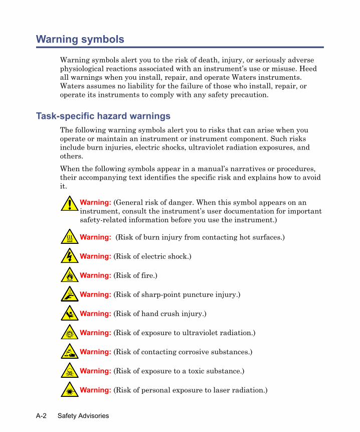
Warning symbols
Warning symbols alert you to the risk of death, injury, or seriously adverse physiological reactions associated with an instrument’s use or misuse. Heed all warnings when you install, repair, and operate Waters instruments. Waters assumes no liability for the failure of those who install, repair, or operate its instruments to comply with any safety precaution.
Task-specific hazard warningsThe following warning symbols alert you to risks that can arise when you operate or maintain an instrument or instrument component. Such risks include burn injuries, electric shocks, ultraviolet radiation exposures, and others. When the following symbols appear in a manual’s narratives or procedures, their accompanying text identifies the specific risk and explains how to avoid it.
Warning: (General risk of danger. When this symbol appears on an instrument, consult the instrument’s user documentation for important safety-related information before you use the instrument.)
Warning: (Risk of burn injury from contacting hot surfaces.)
Warning: (Risk of electric shock.)
Warning: (Risk of fire.)
Warning: (Risk of sharp-point puncture injury.)
Warning: (Risk of hand crush injury.)
Warning: (Risk of exposure to ultraviolet radiation.)
Warning: (Risk of contacting corrosive substances.)
Warning: (Risk of exposure to a toxic substance.)
Warning: (Risk of personal exposure to laser radiation.)
A-2 Safety Advisories

Specific warningsThe following warnings can appear in the user manuals of particular instruments and on labels affixed to them or their component parts.
Burst warning
This warning applies to Waters instruments fitted with nonmetallic tubing.
Warning: (Risk of exposure to biological agents that can pose a serious health threat.)
Warning: (Risk of tipping.)
Warning: (Risk of explosion.)
Warning: (Risk of eye injury.)
Warning: Pressurized nonmetallic, or polymer, tubing can burst. Observe these precautions when working around such tubing:• Wear eye protection.• Extinguish all nearby flames.• Do not use tubing that is, or has been, stressed or kinked.• Do not expose nonmetallic tubing to incompatible compounds like
tetrahydrofuran (THF) and nitric or sulfuric acids.• Be aware that some compounds, like methylene chloride and
dimethyl sulfoxide, can cause nonmetallic tubing to swell, which significantly reduces the pressure at which the tubing can rupture.
Warning symbols A-3
Mass spectrometer flammable solvents warning
This warning applies to instruments operated with flammable solvents.
Mass spectrometer shock hazard
This warning applies to all Waters mass spectrometers.
This warning applies to certain instruments when they are in Operate mode.
Warning: Where significant quantities of flammable solvents are involved, a continuous flow of nitrogen into the ion source is required to prevent possible ignition in that enclosed space. Ensure that the nitrogen supply pressure never falls below 690 kPa (6.9 bar, 100 psi) during an analysis in which flammable solvents are used. Also ensure a gas-fail connection is connected to the LC system so that the LC solvent flow stops if the nitrogen supply fails.
Warning: To avoid electric shock, do not remove the mass spectrometer’s protective panels. The components they cover are not user-serviceable.
Warning: High voltages can be present at certain external surfaces of the mass spectrometer when the instrument is in Operate mode. To avoid non-lethal electric shock, make sure the instrument is in Standby mode before touching areas marked with this high voltage warning symbol.
A-4 Safety Advisories

Biohazard warning
This warning applies to Waters instruments that can be used to process material that might contain biohazards: substances that contain biological agents capable of producing harmful effects in humans.
Chemical hazard warning
This warning applies to Waters instruments that can process corrosive, toxic, flammable, or other types of hazardous material.
Caution symbol
The caution symbol signifies that an instrument’s use or misuse can damage the instrument or compromise a sample’s integrity. The following symbol and its associated statement are typical of the kind that alert you to the risk of damaging the instrument or sample.
Warning: Waters instruments and software can be used to analyze or process potentially infectious human-sourced products, inactivated microorganisms, and other biological materials. To avoid infection with these agents, assume that all biological fluids are infectious, observe Good Laboratory Practices, and consult your organization’s biohazard safety representative regarding their proper use and handling. Specific precautions appear in the latest edition of the US National Institutes of Health (NIH) publication, Biosafety in Microbiological and Biomedical Laboratories (BMBL).
Warning: Waters instruments can be used to analyze or process potentially hazardous substances. To avoid injury with any of these materials, familiarize yourself with the materials and their hazards, observe Good Laboratory Practices (GLP), and consult your organization’s safety representative regarding proper use and handling. Guidelines are provided in the latest edition of the National Research Council's publication, Prudent Practices in the Laboratory: Handling and Disposal of Chemicals.
Caution: To avoid damage, do not use abrasives or solvents to clean the instrument’s case.
Caution symbol A-5

Warnings that apply to all Waters instruments
When operating this device, follow standard quality control procedures and the equipment guidelines in this section.
Attention: Changes or modifications to this unit not expressly approved by the party responsible for compliance could void the user’s authority to operate the equipment.
Important: Toute modification sur cette unité n’ayant pas été expressément approuvée par l’autorité responsable de la conformité à la réglementation peut annuler le droit de l’utilisateur à exploiter l’équipement.
Achtung: Jedwede Änderungen oder Modifikationen an dem Gerät ohne die ausdrückliche Genehmigung der für die ordnungsgemäße Funktionstüchtigkeit verantwortlichen Personen kann zum Entzug der Bedienungsbefugnis des Systems führen.
Avvertenza: qualsiasi modifica o alterazione apportata a questa unità e non espressamente autorizzata dai responsabili per la conformità fa decadere il diritto all'utilizzo dell'apparecchiatura da parte dell'utente.
Atencion: cualquier cambio o modificación efectuado en esta unidad que no haya sido expresamente aprobado por la parte responsable del cumplimiento puede anular la autorización del usuario para utilizar el equipo.
注意:未經有關法規認證部門允許對本設備進行的改變或修改,可能會使使用者喪失操作該設
備的權利。
注意:未经有关法规认证部门明确允许对本设备进行的改变或改装,可能会使使用者丧失操作该设备的合法性。
주의: 규정 준수를 책임지는 당사자의 명백한 승인 없이 이 장치를 개조 또는 변경할 경우, 이 장치를 운용할 수 있는 사용자 권한의 효력을 상실할 수 있습니다.
注意:規制機関から明確な承認を受けずに本装置の変更や改造を行うと、本装置のユーザーとしての承認が無効になる可能性があります。
A-6 Safety Advisories

Warning: Use caution when working with any polymer tubing under pressure:• Always wear eye protection when near pressurized polymer tubing.• Extinguish all nearby flames.• Do not use tubing that has been severely stressed or kinked.• Do not use nonmetallic tubing with tetrahydrofuran (THF) or concentrated
nitric or sulfuric acids.• Be aware that methylene chloride and dimethyl sulfoxide cause nonmetallic
tubing to swell, which greatly reduces the rupture pressure of the tubing.Attention: Manipulez les tubes en polymère sous pression avec precaution:• Portez systématiquement des lunettes de protection lorsque vous vous
trouvez à proximité de tubes en polymère pressurisés.• Eteignez toute flamme se trouvant à proximité de l’instrument.• Evitez d'utiliser des tubes sévèrement déformés ou endommagés.• Evitez d'utiliser des tubes non métalliques avec du tétrahydrofurane (THF)
ou de l'acide sulfurique ou nitrique concentré.• Sachez que le chlorure de méthylène et le diméthylesulfoxyde entraînent le
gonflement des tuyaux non métalliques, ce qui réduit considérablement leur pression de rupture.
Vorsicht: Bei der Arbeit mit Polymerschläuchen unter Druck ist besondere Vorsicht angebracht:• In der Nähe von unter Druck stehenden Polymerschläuchen stets
Schutzbrille tragen.• Alle offenen Flammen in der Nähe löschen.• Keine Schläuche verwenden, die stark geknickt oder überbeansprucht sind.• Nichtmetallische Schläuche nicht für Tetrahydrofuran (THF) oder
konzentrierte Salpeter- oder Schwefelsäure verwenden.• Durch Methylenchlorid und Dimethylsulfoxid können nichtmetallische
Schläuche quellen; dadurch wird der Berstdruck des Schlauches erheblich reduziert.
Warnings that apply to all Waters instruments A-7

Attenzione: fare attenzione quando si utilizzano tubi in materiale polimerico sotto pressione:• Indossare sempre occhiali da lavoro protettivi nei pressi di tubi di polimero
pressurizzati.• Spegnere tutte le fiamme vive nell'ambiente circostante.• Non utilizzare tubi eccessivamente logorati o piegati.• Non utilizzare tubi non metallici con tetraidrofurano (THF) o acido solforico
o nitrico concentrati.• Tenere presente che il cloruro di metilene e il dimetilsolfossido provocano
rigonfiamenti nei tubi non metallici, riducendo notevolmente la pressione di rottura dei tubi stessi.
Advertencia: se recomienda precaución cuando se trabaje con tubos de polímero sometidos a presión:• El usuario deberá protegerse siempre los ojos cuando trabaje cerca de tubos
de polímero sometidos a presión.• Si hubiera alguna llama las proximidades.• No se debe trabajar con tubos que se hayan doblado o sometido a altas
presiones.• Es necesario utilizar tubos de metal cuando se trabaje con tetrahidrofurano
(THF) o ácidos nítrico o sulfúrico concentrados.• Hay que tener en cuenta que el cloruro de metileno y el sulfóxido de dimetilo
dilatan los tubos no metálicos, lo que reduce la presión de ruptura de los tubos.
警告:當在有壓力的情況下使用聚合物管線時,小心注意以下幾點。
• 當接近有壓力的聚合物管線時一定要戴防護眼鏡。
• 熄滅附近所有的火焰。
• 不要使用已經被壓癟或嚴重彎曲管線。
• 不要在非金屬管線中使用四氫呋喃或濃硝酸或濃硫酸。
• 要了解使用二氯甲烷及二甲基亞楓會導致非金屬管線膨脹,大大降低管線的耐壓能力。
A-8 Safety Advisories

警告:当有压力的情况下使用管线时,小心注意以下几点:
• 当接近有压力的聚合物管线时一定要戴防护眼镜。
• 熄灭附近所有的火焰。
• 不要使用已经被压瘪或严重弯曲的管线。
• 不要在非金属管线中使用四氢呋喃或浓硝酸或浓硫酸。
• 要了解使用二氯甲烷及二甲基亚枫会导致非金属管线膨胀,大大降低管线的耐压能力。
경고: 가압 폴리머 튜브로 작업할 경우에는 주의하십시오.• 가압 폴리머 튜브 근처에서는 항상 보호 안경을 착용하십시오.• 근처의 화기를 모두 끄십시오.• 심하게 변형되거나 꼬인 튜브는 사용하지 마십시오.• 비금속(Nonmetallic) 튜브를 테트라히드로푸란(Tetrahydrofuran: THF) 또는 농축 질산 또는 황산과 함께 사용하지 마십시오.
• 염화 메틸렌(Methylene chloride) 및 디메틸술폭시드(Dimethyl sulfoxide)는 비금속 튜브를 부풀려 튜브의 파열 압력을 크게 감소시킬 수 있으므로 유의하십시오.
警告:圧力のかかったポリマーチューブを扱うときは、注意してください。
• 加圧されたポリマーチューブの付近では、必ず保護メガネを着用してください。
• 近くにある火を消してください。
• 著しく変形した、または折れ曲がったチューブは使用しないでください。
• 非金属チューブには、テトラヒドロフラン(THF)や高濃度の硝酸または硫酸などを流
さないでください。
• 塩化メチレンやジメチルスルホキシドは、非金属チューブの膨張を引き起こす場合があり、その場合、チューブは極めて低い圧力で破裂します。
Warnings that apply to all Waters instruments A-9

Warning: The user shall be made aware that if the equipment is used in a manner not specified by the manufacturer, the protection provided by the equipment may be impaired.
Attention: L’utilisateur doit être informé que si le matériel est utilisé d’une façon non spécifiée par le fabricant, la protection assurée par le matériel risque d’être défectueuses.
Vorsicht: Der Benutzer wird darauf aufmerksam gemacht, dass bei unsachgemäßer Verwenddung des Gerätes die eingebauten Sicherheitseinrichtungen unter Umständen nicht ordnungsgemäß funktionieren.
Attenzione: si rende noto all'utente che l'eventuale utilizzo dell'apparecchiatura secondo modalità non previste dal produttore può compromettere la protezione offerta dall'apparecchiatura.
Advertencia: el usuario deberá saber que si el equipo se utiliza de forma distinta a la especificada por el fabricante, las medidas de protección del equipo podrían ser insuficientes.
警告:使用者必須非常清楚如果設備不是按照製造廠商指定的方式使用,那麼該設備所提供的保護將被消弱。
警告:使用者必须非常清楚如果设备不是按照制造厂商指定的方式使用,那么该设备所提供的保护将被削弱。
경고: 제조업체가 명시하지 않은 방식으로 장비를 사용할 경우 장비가 제공하는 보호 수단이 제대로 작동하지 않을 수 있다는 점을 사용자에게 반드시 인식시켜야 합니다.
警告: ユーザーは、製造元により指定されていない方法で機器を使用すると、機器が提供している保証が無効になる可能性があることに注意して下さい。
A-10 Safety Advisories

Warning: To protect against fire, replace fuses with those of the type and rating printed on panels adjacent to instrument fuse covers.Attention: pour éviter tout risque d'incendie, remplacez toujours les fusibles par d'autres du type et de la puissance indiqués sur le panneau à proximité du couvercle de la boite à fusible de l'instrument.Vorsicht: Zum Schutz gegen Feuer die Sicherungen nur mit Sicherungen ersetzen, deren Typ und Nennwert auf den Tafeln neben den Sicherungsabdeckungen des Geräts gedruckt sind.Attenzione: per garantire protezione contro gli incendi, sostituire i fusibili con altri dello stesso tipo aventi le caratteristiche indicate sui pannelli adiacenti alla copertura fusibili dello strumento.Advertencia: Para evitar incendios, sustituir los fusibles por aquellos del tipo y características impresos en los paneles adyacentes a las cubiertas de los fusibles del instrumento.
警告 : 為了避免火災,更換保險絲時,請使用與儀器保險絲蓋旁面板上所印刷之相同類型與規格的保險絲。
警告 : 为了避免火灾,应更换与仪器保险丝盖旁边面板上印刷的类型和规格相同的保险丝。
경고: 화재의 위험을 막으려면 기기 퓨즈 커버에 가까운 패널에 인쇄된 것과 동일한 타입 및 정격의 제품으로 퓨즈를 교체하십시오.
警告 : 火災予防のために、ヒューズ交換では機器ヒューズカバー脇のパネルに記載されているタイプおよび定格のヒューズをご使用ください。
Warnings that apply to all Waters instruments A-11

Electrical and handling symbols
Electrical symbolsThese can appear in instrument user manuals and on the instrument’s front or rear panels.
Electrical power on
Electrical power off
Standby
Direct current
Alternating current
Protective conductor terminal
Frame, or chassis, terminal
Fuse
Recycle symbol: Do not dispose in municipal waste.
A-12 Safety Advisories
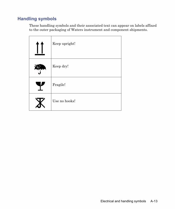
Handling symbolsThese handling symbols and their associated text can appear on labels affixed to the outer packaging of Waters instrument and component shipments.
Keep upright!
Keep dry!
Fragile!
Use no hooks!
Electrical and handling symbols A-13

A-14 Safety Advisories

B Specifications
This appendix includes information on:• Operational specifications• Mechanical specifications• Environmental specifications• Electrical specifications• Communications
Operational specifications
Condition SpecificationDrift Less than 0.05 μS/hr/°C (ambient)
Base: 200 μSSensitivity: 0.005Eluent: 1 mM KCI
Noise Less than 0.005 μS/cmBase: 200 μSSensitivity: 0.005Eluent: 1 mM KCI
Temperature control Front-panel selectable: OFF, 30, 35, 40, 45, 50, 55, 60, 65 °CPerformance: 0.5 °C/hr
Response times Fast: 0.25 secStandard: 0.5 secSlow: 1.0 sec
Mechanical specifications
Condition SpecificationCell volume 0.6 μL
B-1

Wetted materials 316 stainless steel, PTFE, and PCTFEOperating pressure 70 psi maximumHeight 9.4 inches (23.8 cm)Length 21 inches (53.3 cm)Width 11.5 inches (29.2 cm)Weight 17.7 pounds (8 kg)
Environmental specifications
Condition SpecificationOperating temperature range 4 to 35 °C
(40 to 95 °F)Operating humidity 20 to 80% RH, noncondensing
Electrical specifications
Condition SpecificationProtection classa Class I
Over-voltage categoryb II
Pollution degreec 2
Moisture protectiond Normal (IPXO)
Line voltages (grounded AC), nominal 100/120 VAC220/240 VAC
Line frequency ranges 50 Hz: ±2 Hz60 Hz: ±2 Hz
100/120 VAC fuse rating T2 A (20 mm)220/240 VAC fuse rating T1 A (20 mm)Current (Max) 0.6 A
a. Protection Class I – The insulating scheme used in the instrument to protect you from electrical shock. Class I identifies a single level of insulation between live parts (wires) and exposed conductive parts (metal panels), in which the exposed conductive parts are connected to a grounding system. In turn, this grounding system is connected to the third pin (ground pin) on the electrical power cord plug.
Mechanical specifications (Continued)
Condition Specification
B-2 Specifications

b. Over Voltage Category II – Pertains to instruments that receive their elec-trical power from a local level such as an electrical wall outlet.
c. Pollution Degree 2 – A measure of pollution on electrical circuits, which may produce a reduction of dielectric strength or surface resistivity. Degree 2 refers to normally only nonconductive pollution. Occasionally, however, a temporary conductivity caused by condensation must be expected.
d. Moisture Protection – Normal (IPXO) – IPXO means that there is NO Ingress Protection against any type of dripping or sprayed water. The X is a placeholder to identify protection against dust, if applicable.
Communications
Signal SpecificationRecorder output 0 to 10 mVIntegrator output 10, 50, 100 μS/1V FSMarker output Isolated contact outputController bus IEEE-488, PowerLine™
B-3

B-4 Specifications

C Spare Parts
The parts listed in the table below are spare parts recommended for installation by you, the customer. Any parts that are not listed may require installation by a trained service representative. Order a supply of the parts listed below to keep in stock for use as needed.
Tip: The flow cell (part number 043069) is considered a replacement part. Order the flow cell only when it is needed for replacement in the Waters 432 Detector.Fill in the information below for easy reference when you order parts or request service.
Installation Date: _____________
Serial Number: ____________
Spare parts
Item Quantity Part numberFuse, Time Delay, 1A, 250V, IEC 2 WAT165-11Fuse, Time Delay, 2A, 5x20 mm T 2 WAT165-14Fitting kit 1 WAT025604Pump Seal Replacement kit 2 WAT022934Union 1 WAT097332
C-1

C-2 Spare Parts

D Ion Chromatography Methods
Contents
Topic PageGeneral anion analysis using conductivity and UV detection D-2Alkali and alkaline earth cations, ammonium, and amines D-15
D-1

General anion analysis using conductivity and UV detection
Common anion standards
Required instrumentation
Instrument Part numberAlliance, 2695 Separations Module or Breeze (with column heater, seal wash, and degasser)
N/A
432 Conductivity Detector 043061busSAT/IN Module 200415Empower/Breeze data processing Contact Waters
Analysis conditions
Condition ValueColumn IC-Pak A/HR (part number 026765)Eluent Borate/gluconate containing 12% AcCNBack conductivity 240 ±20 μS
D-2 Ion Chromatography Methods

Preparing eluent
To prepare eluent:
1. Add 20 mL of lithium borate/gluconate concentrate and 120 mL of HPLC-grade acetonitrile (AcCN) into a 1-liter volumetric flask (see “Preparing lithium borate/gluconate 50X stock concentrate” on page D-13, for concentrate preparation).
2. Dilute to volume with DI water.
3. Ensure the natural pH is 8.2 ±0.1.
4. Vacuum degas through a 0.45-μm aqueous and solvent-compatible membrane filter.
5. Store in a glass or plastic container at ambient temperature. Discard after 1 month.
Preparing standardsIt is recommended that you use certified 1000-ppm anion standards with this method. If unavailable, see “Preparing stock reagent” on page D-21, for uncertified standard preparation.Prepare at least three mixed analyte standards within the expected range of sample analyte concentration. This method is linear from 0.1 to 100 ppm.
Degas ContinuousFlow rate 1 mL/min.Backpressure 1200 ±200 psiTemperature 30 °C for column heater, 35 °C for detectorInjection 100 μLNeedle wash 12% AcCN in DI waterDetection Direct conductivityBase range 500Attenuation 50 μS/Volt unattenuatedPolarity Positive
Analysis conditions (Continued)
Condition Value
General anion analysis using conductivity and UV detection D-3

After you validate the multi-point calibration curve, a single-point calibration curve within the expected analyte concentration range is appropriate for recalibration.
Preparing a sample
To prepare a sample:
1. Determine the expected range of analyte concentration and other anionic component in the sample matrix. The major analyte should be less than 100 ppm for best results.
2. Dilute the sample with DI water, if necessary.
3. If the sample contains high amounts of neutral organics or is highly colored, pass the diluted sample through a C18 Sep-Pak cartridge. Anions pass through unretained, but there can be a loss of fluoride recovery.
4. Filter samples containing suspended solids through a 0.45-μm aqueous-compatible disk before injection. Failure to filter solids can increase column backpressure.Tip: For best results, ensure sample pH is between 3 and 11.
Samples treated with a sample preparation disk in the H+ form, used to remove cations and neutralize high pH, will yield chromatograms similar to suppressed conductivity chromatograms.
D-4 Ion Chromatography Methods

Empower data processing method
Method validationThis validation design is abstracted from ASTM/EPA validation. It has been used to validate all anion analysis methods. Many of the methods using this
IC processing method using peak apex for retention time
Process ValuesIntegration Peak Width = 30.0
Minimum Area = 3000Inhibit Intg. = 0 to 2 min.Threshold = 10 to 25Minimum Height = 150
Calibration Averaging = NoneUpdate RT = NeverPeak Match = ClosestQuant By = Peak AreaFit Type = Linear for multi-point calibration, Linear Through Zero for single-point calibration
Report Analyte NameAnalyte Retention TimePeak AreaAmounts
General anion analysis using conductivity and UV detection D-5

validation design are linear above 50 ppm.
Method linearity
Calibration curves for chloride, fluoride, and bromide
Method validation
Individual youden pair standard, in ppmA
naly
te a
nion
1 2 3 4 5 6 7 8Cl 0.7 2.0 3.0 15.0 40.0 20.0 50.0 0.5Br 2.0 3.0 15.0 40.0 20.0 50.0 0.7 0.5NO2 3.0 40.0 20.0 15.0 50.0 0.5 2.0 0.7SO4 40.0 50.0 0.5 0.7 2.0 3.0 15.0 20.0NO3 15.0 20.0 40.0 50.0 0.5 0.7 2.0 3.0F 2.0 0.7 0.5 3.0 10.0 7.0 20.0 25.0PO4 50.0 40.0 20.0 0.5 3.0 2.0 0.7 15.0
Cl r2 = 0.9999
F r2 = 0.9986
Br r2 = 0.9999
D-6 Ion Chromatography Methods

Calibration curves for nitrite and nitrate
Calibration curves for sulfate and phosphate
NO2 r2 = 0.9999
NO3 r2 = 0.9992
SO4 r2 = 0.9999
PO4 r2 = 0.9992
General anion analysis using conductivity and UV detection D-7

Quantitation precisionQuantitation Precision is the percent RSD of analyte peak area at each concentration. Data is based on seven replicate injections of the validation standards.
Quantitation precision
Analyte F CI NO2 Br NO3 PO4 SO4
ppm
Con
cent
ratio
n
0.5 0.95 1.11 3.44 5.17 0.32 12.98 7.620.7 0.67 1.64 0.78 1.73 0.75 9.29 3.902 0.17 0.18 0.56 1.14 0.91 2.91 1.073 0.43 0.17 0.20 0.67 0.19 3.49 0.6415 0.44 0.05 0.28 0.11 0.16 0.50 0.3220 0.45 0.04 0.05 0.30 0.06 0.52 0.2540 0.05 0.04 0.03 0.08 0.37 0.2650 0.13 0.02 0.26 0.03 1.56 0.16
D-8 Ion Chromatography Methods

Method detection limits
100-μL injection
Based on this representative chromatogram using a 100-μL injection, the estimated detection limits, as ppb, at three times signal to noise (S/N) are as follows:
• Fluoride = 50• Chloride = 25• Nitrite = 50• Bromide = 75• Nitrate = 75• Phosphate = 125• Sulfate = 75
Quantitation below these detection limits is not advised. You can obtain lower detection limits using a 250-μL injection.
General anion analysis using conductivity and UV detection D-9

Quantitation accuracyThe Certified Performance Evaluation Standards were diluted 1:100 with DI water. Amounts are based on a multi-point calibration curve prepared from certified standards.
Analyte recoveryThe Certified Performance Evaluation Standards were diluted 1:100 with typical drinking water. Amounts are based on a multi-point calibration.
Quantitation accuracy
Analyte F CI NO2 NO3 PO4 SO4
Performance Evaluation Standard
True Value in ppm
2.69 43.00 1.77 15.37 6.29 37.20
Official Anion Methods Wet Chem & IC
Measured Mean
2.75 43.30 1.77 15.42 6.38 37.00
Measured Std Dev
0.26 3.09 0.07 1.15 0.21 2.24
IC UsingAlliance IC Pak A/HR and B/G Eluent
Ave IC n=3 2.63±0.05
43.87±0.09
1.93±0.01
15.04±0.06
6.47±0.09
37.03±0.12
IC/Mean 0.956 1.013 1.090 0.975 1.014 1.001IC/True Value
0.978 1.020 1.090 0.979 1.029 0.995
Analyte recovery
Analyte F CI NO2 NO3 PO4 SO4
Milford Drinking Water n=3, as ppm
Not detected
25.82±0.04
Not detected
0.23±0.002
Not detected
8.300.02
%RSD 0.16 0.92 0.27
Performance Evaluation Std
2.69 43.00 1.77 15.37 6.29 37.20
D-10 Ion Chromatography Methods

Example of use
Typical drinking water, no dilution required
Using direct UV detectionMany anions are UV active in the range of 205 to 214 nm, such as NO2, Br, and NO3, and the use of direct UV detection provides a degree of detector selectivity. The figure “Direct UV detection” on page D-12 shows the chromatogram of the anion standard that demonstrates this selectivity. Generally, the lower the wavelength of detection, the greater is the response, as seen with the difference between 205- and 214-nm chromatograms. However, the borate/gluconate eluent has some UV absorption which causes
MDW + PES n=3; as ppm
2.46±0.04
69.64±0.08
1.82±0.004
15.52±0.02
5.35±0.05
46.46±0.17
%RSD 1.51% 0.11% 0.21% 0.10% 0.92% 0.37%
% Recovery 91.4% 102.5% 102.8% 99.5% 85.1% 102.8%
Analyte recovery (Continued)
Analyte F CI NO2 NO3 PO4 SO4
General anion analysis using conductivity and UV detection D-11

negatives peaks at the retention time of the UV transparent anion, such as F, Cl, PO4, and SO4, if present.
Direct UV detection
Direct UV detection is five times more responsive for nitrite and nitrate than is conductivity detection and therefore provides lower detection limits. The chromatogram in figure “100-ppb anion standard” on page D-13 of a 100-ppb anion standard demonstrates the improved sensitivity.
D-12 Ion Chromatography Methods

100-ppb anion standard
The borate/gluconate eluent has some UV absorption. Use of eluents that are UV transparent, such as hydroxide and carbonate/bicarbonate, provide lower detection limits.
Preparing lithium borate/gluconate 50X stock concentrate
To prepare lithium borate/gluconate 50X stock concentrate:
1. Using a 60-mL plastic syringe, add approximately 25 g of BioRad AG-50W-X12 strong cation exchange resin in the hydrogen form, or equivalent. Wash the resin with five 20-mL portions of DI water to remove any ionic impurities from the resin. Discard the washings.
2. Dissolve 9.06 g of sodium gluconate in approximately 20-mL of DI water. After dissolution, transfer this solution into the 60-mL syringe with resin. Slowly pass this solution into a 1-liter volumetric flask. Wash the resin with five 20-mL portions of DI water, then add the washing to the volumetric flask. Discard the syringe and resin.An alternative is to use commercially available 50% gluconic acid. However, it comes as a brown solution that, when diluted, gives a yellow tint to the eluent that can affect long-term performance. You can remove the brown color by passing 5 mL of 50% gluconic acid through a C18
Waters 996 photodiode array detector
General anion analysis using conductivity and UV detection D-13

Sep-Pak cartridge. This requires three Sep-Pak cartridges. Use 13.2 mL of 50% gluconic acid for the eluent concentrate.
3. Adjust the volume in the flask to approximately 500 mL with DI water and use a stirring bar. Add 7.2 g of lithium hydroxide monohydrate and 25.5 g of boric acid. With the aid of a magnetic stirrer, mix until all reagents are dissolved.
4. Add 94 mL of 95% glycerol and mix. Remove the stirring bar and fill to the mark with DI water.
5. Store this lithium borate/gluconate concentrate in a plastic container at ambient temperature for up to 6 months. You can store it at 4 °C for up to 1 year, but warm it to ambient temperature before use.
6. A white “string-like” material observed at the bottom of the container indicates significant microbiological growth. If present, discard and prepare again.
Preparing lithium borate/gluconate eluent
To prepare lithium borate/gluconate eluent:
1. In a 1-liter volumetric flask, add 20 mL of the 50X lithium borate/gluconate concentrate and dissolve in 500 mL of DI water. Add 120 mL of HPLC-grade acetonitrile. Mix and fill to the mark with DI water.
2. Vacuum degas through a 0.45-μm aqueous / organic membrane.The background conductivity of the lithium borate/gluconate eluent is between 220 and 270 μS.
D-14 Ion Chromatography Methods

Alkali and alkaline earth cations, ammonium, and amines
1-ppm standard
Required instrumentation
Instrument Part numberAlliance, 2695 Separations Module or Breeze (with column heater, seal wash, and degasser)
N/A
432 Conductivity Detector 043061busSAT/IN Module 200415Empower/Breeze data processing Contact Waters
Analysis conditions
Condition ValueColumn IC-Pak C/MDEluent 3 mM HNO3/0.1 mM EDTABack conductivity 1250 ±50 μS
Alkali and alkaline earth cations, ammonium, and amines D-15

Preparing eluent
To prepare eluent:
1. Add 0.029 g of EDTA as the free acid into a 1-liter plastic volumetric flask.
2. Dissolve in 500 mL of DI water with a stirring bar for 30 min.
3. Add 30 mL of 100 mM HNO3 (or 189 μL of concentrated HNO3).
4. Dilute to volume with DI water.
5. Vacuum degas through a 0.45-μm aqueous-compatible membrane to remove excess EDTA crystals.
6. Store in a plastic container at ambient temperature. Discard after 1 month.
Preparing standardsIt is recommended that you use certified 1000-ppm anion standards with this method. If unavailable, see “Preparing stock reagent” on page D-21, for uncertified standard preparation.Prepare at least three mixed analyte standards, using plastic volumetric flasks, within the expected range of the sample analyte concentration. This
Degas ContinuousFlow rate 1 mL/min.Backpressure 2100 psiTemperature 30 °C for column heater, 35 °C for detectorInjection 100 μLNeedle wash 12% AcCN in DI waterDetection Indirect conductivityBase range 2000Attenuation 100 μS/Volt unattenuatedPolarity Negative
Analysis conditions (Continued)
Condition Value
D-16 Ion Chromatography Methods

method is linear from 0.05 to 20 ppm for lithium, sodium, and ammonium, and 0.05 to 50 ppm for potassium, magnesium, and calcium. Above these concentrations, the response is off scale. After the multi-point calibration curve is validated, a single-point calibration curve within the expected analyte concentration is appropriate for future calibrations.You can use this method for the analysis of Rb, Cs, Sr, and Ba.
Preparing a sample
To prepare a sample:
1. Determine the expected range of analyte concentration and other anionic component in the sample matrix. Sodium should be less than 20-ppm for best results.
2. Dilute the sample with DI water, if necessary.
3. If the sample contains high amounts of neutral organics or is highly colored, pass the diluted sample through a C18 Sep-Pak cartridge. Cations pass through unretained. There can be residual Na contamination from the cartridge.
4. Filter samples containing suspended solids through a 0.45-μm aqueous-compatible disk before injection. Failure to filter solids can increase column backpressure.Tip: For best results, ensure sample pH is between 2 and 7 (especially the alkaline earth cations). Samples with pH less than 10 are appropriate for the alkali cations, ammonium, and amines.
5. For samples with pH less than 2, dilute the sample 1:10 with DI water or treat the sample with an Alltech IC-OH cartridge to remove anions and neutralize pH.
Alkali and alkaline earth cations, ammonium, and amines D-17

Empower data processing methodIC processing method using peak apex for retention time
Process ValuesIntegration Peak Width = 30.0
Minimum Area = 3000Inhibit Intg. = 0 to 2 min.Threshold = 25 to 40Minimum Height = 500
Calibration Averaging = NoneUpdate RT = NeverPeak Match = ClosestQuant By = Peak AreaFit Type = Linear for multi-point calibration, Linear Through Zero for single-point calibration
Report Analyte NameAnalyte Retention TimePeak AreaAmounts
D-18 Ion Chromatography Methods

Method detection limits
25-ppb cation standard
Based on this representative chromatogram using a 100-μL injection in a 2695 Separations Module, the estimated detection limits, as ppb, at three times signal to noise (S/N) are as follows:
• Lithium = 1• Potassium = 15• Sodium = 5• Magnesium = 10• Ammonium = 5• Calcium = 15
You can achieve lower detection limits by using a 250-μL injection.
Alkali and alkaline earth cations, ammonium, and amines D-19

Examples of use
Typical drinking water, no dilution required
Typical municipal wastewater, diluted 1:50, overlay of duplicate injections
Tip: Alkyl and alkanol amine analysis standards are between 1 and 5 ppm, 3 mM HNO3/0.1 mM EDTA/3% AcCN.
D-20 Ion Chromatography Methods

Preparing stock reagentBecause it is difficult to prepare a stock eluent for this column, it is recommended to prepare fresh working eluent.
To prepare stock reagent:
1. In a 1-liter plastic volumetric flask, add 0.029 g of EDTA (as the free acid, not its salts) in 800 mL of DI water. Place on a magnetic stir plate and stir for 10 minutes.
2. While stirring, add 189 μL of concentrated nitric acid and mix for 5 minutes.
3. Remove the stirring bar and fill to the mark with DI water.
4. Filter through a 0.45-μm aqueous-compatible membrane filter before use. There can be some remaining white crystals on the filter (EDTA). This does not affect the performance of the eluent. Discard the filter.
Alkali and alkaline earth cations, ammonium, and amines D-21

D-22 Ion Chromatography Methods

E Validation Support
Contents
Topic PageValidation regulation overview E-2Waters regulatory compliance support E-2
E-1

Validation regulation overview
Federal regulatory codes require that instrumentation and automated systems used for generation, measurement, and assessment of data undergo:
• Operational qualification (performance verification) following repairs, maintenance, and substantial periods of operation
• Routine maintenanceFederal regulatory codes also require that laboratories maintain:
• Written Standard Operating Procedures (SOPs) that indicate dates of operational qualification and maintenance
• Logs of resultsTip: Designate a person to be responsible for maintaining federally required records.
Waters regulatory compliance support
Waters provides a wide range of documentation and services to assist customers in complying with the following areas of Standard Operating Procedure regulatory requirements:
• Basic operation• Instrument maintenance• Error messages, diagnostics, and tests• Instrument performance qualification (calibration)
Basic operationRegulatory requirements regarding proper instruction for preparing, programming, and operating the 432 Detector are satisfied by the Waters 432 Conductivity Detector Operator’s Guide.
E-2 Validation Support

Instrument maintenanceChapter 5 satisfies regulatory requirements for routine instrument maintenance. Chapter 5 includes:
• Maintenance considerations• Calibration adjustment• Replacing the flow cell• Replacing fuses• Summary of 432 Detector error messages• Troubleshooting tables
Additional Waters supportFor more information about compliance support products and services, contact Waters Technical Service Department.
Waters regulatory compliance support E-3

E-4 Validation Support

Index
Aaudience and purpose ivAuto Base 3-5Auto Zero 2-10, 2-13, 2-21, 3-5
BBalance 2-13Balance key 3-5Base Range 3-10Base Range key 3-4Baseline
drift 5-10, 5-11noise 5-9
Beep-on-error 3-7Beep-on-keystroke 3-7biohazard warning A-5Bubbles, removing 5-8burst warning A-3Bus LAC/E connections 2-15Bus SAT/IN connections 2-14
CCarbonate absorption, minimizing 4-3caution symbol A-5Chart Mark key 3-6Chart recorder connections 2-19Chart recorder offset 3-5chemical hazard warning A-5Clear key 3-6Compression screw 2-26Configuration, system 4-5Connections
auto zero input 2-21Bus SAT/IN to Bus LAC/E 2-15chart recorder 2-19marker input 2-20Millennium32 2-13
PowerLine controller 2-11Containers, selecting and preparing
4-2Contamination, removal. See
passivation
DDisplay 3-2
EEC Authorized Representative vielectrical symbols A-12Eluent
anion, preparing 4-7cation, preparing 4-8general guidelines 4-6high-pH 4-3nitric acid, preparing 4-8
Eluent handling 3-10equipment guidelines iv, A-6Error messages 3-3, 5-7
Fflammable solvents A-4Flow cell
removing bubbles 5-8theory 1-3
Fluid connectionsassembling fittings 2-26making connections 2-27
Hhandling symbols A-13
IIEEE-488
address 2-12connector 2-10
Index-1
Initialization self-test 3-2Integrator
offset 3-5output 2-9, 3-10sensitivity 2-13sensitivity range multiplier 3-4
intended use vISM classification v
KKey descriptions 3-7
LLAC/E connections. See Bus LAC/E
connectionsLeak Alert output 2-10
MMarker input 2-10, 2-20Marker output 2-9, 2-19, 3-6mass spectrometer shock hazard A-4Millennium32 connections 2-13
NNitric acid eluent, preparing 4-8Noisy baseline, troubleshooting 5-9
OOffset
chart recorder 3-5integrator 3-5polarity 3-5
PPassivation 2-29Polarity key 3-4, 3-10Power requirements 2-2Power switch 3-2PowerLine operation 2-13Pulse dampener 2-27, 4-6purpose and audience iv
RRecorder
output 2-9, 2-19, 3-10sensitivity 2-13
Remote key 3-4Response key 3-5
Ssafety advisories A-1Sample preparation 4-5Sensitivity Range key 3-4Shift key 3-6Soda lime tube, using 4-4Specifications B-1Standards
anion, injecting 4-10anion, preparing 4-9cation, injecting 4-14cation, preparing 4-12concentration 4-8shelf-life 4-8
Standby setup 3-9Storage, long-term 3-9symbols
caution A-5electrical A-12handling A-13warning A-2
System configuration 4-5
TTemperature equilibration 3-9Temperature key 3-5Time constant, detector 3-5Troubleshooting 5-6Tubing
cutting polymeric 2-25cutting steel 2-24
Index-2

UUnpacking the 432 Detector 2-3
VVoltage, operating 2-6–2-7
ranges 2-6
Wwarning symbols A-2, A-6Water purity 4-2
I
Index-3

Index-4