Operator’s Manual Environmental Surveillance over the Internet
80
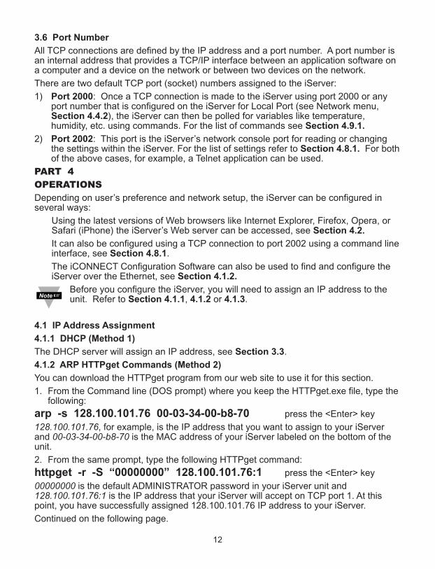
http://192.168.1.200 Address Chart 1 Hour/Div 20.0 C/Div 10.0 %/Div Temperature Humidity Max. 130.1 / Min. 95.9 Max. 69.9 / Min. 30.1 High 150.0 / Low 78.0 High 78.0 / Low 25.0 100 0 200 0 Save Chart Print Chart 108.2 F 50.8 % Thu Sep 17 12:05:07 PDT 2009 Thu Sep 16 08:00:00 PDT 2009 Data Source: Alarm Relay Set Points: Y-axis (right): Live Bold Humidity Style: Bold Y-axis (left): Temperature Style: Bold X-axis: 1 Day Readings Chart Web Link Setup Recording: ON Help[? ] Temperature + Humidity Operator’s Manual Environmental Surveillance over the Internet http://www.newportUS.com/manuals ® NEWPORT Electronics, Inc.
Transcript of Operator’s Manual Environmental Surveillance over the Internet

http://192.168.1.200Address
Chart
1 Hour/Div
20.0C/Div
10.0%/Div
Temperature Humidity
Max. 130.1 / Min. 95.9 Max. 69.9 / Min. 30.1High 150.0 / Low 78.0 High 78.0 / Low 25.0
100
0
200
0
Save Chart
Print Chart
108.2 F 50.8 %
Thu Sep 17 12:05:07 PDT 2009Thu Sep 16 08:00:00 PDT 2009
Data Source:
Alarm Relay Set Points:
Y-axis (right):
Live
Bold
Humidity Style: Bold
Y-axis (left): Temperature Style: Bold
X-axis: 1 Day
Readings Chart Web Link Setup
Recording: ON
Help[?]
Temperature + HumidityOperator’s Manual
Environmental Surveillance over the Internet
http://www.newportUS.com/manuals
® NEWPORT Electronics,Inc.

CountersFrequency Meters
PID ControllersClock/Timers
PrintersProcess Meters
On/OffControllersRecordersRelativeHumidity
TransmittersThermocouples
ThermistorsWire
Wireless
Rate MetersTimers
TotalizersStrain Gauge
MetersVoltmetersMultimeters
Soldering IronTesterspH pens
pH ControllerspH Electrodes
RTDsThermowellsFlow Sensors
For Immediate AssistanceIn the U.S.A. and Canada: 1-800-NEWPORT®
In Mexico: (95) 800-NEWPORTSM
Or call your local NEWPORT Office.
Internet [email protected]
Additional products from
NEWPORTnetSM On-Line Servicewww.newportUS.com
® NEWPORT Electronics,Inc.
It is the policy of NEWPORT to comply with all worldwide safety and EMC/EMI regulations that apply. NEWPORT is constantlypursuing certification of its products to the European New Approach Directives. NEWPORT will add the CE mark to everyappropriate device upon certification.
The information contained in this document is believed to be correct but NEWPORT Electronics, Inc. accepts no liability for anyerrors it contains, and reserves the right to alter specifications without notice.
WARNING: These products are not designed for use in, and should not be used for, patient connected applications.
TRADEMARK NOTICE: , NEWPORT®, NEWPORT® and newportUS.com are trademarks of NEWPORT Electronics, Inc.PATENT NOTICE: This product is covered by one or more of the following patents: U.S. Pat. No. Des. 336,895; 5,274,577/CANADA 2052599; 2052600/ ITALY 1249456; 1250938 / FRANCE BREVET No. 91 12756 / SPAIN 2039150; 2048066 / UKPATENT No. GB2 249 837; GB2 248 954 / GERMANY DE 41 34398 C2. The ® is a Trademark of OMEGA Engineering, Inc.Used Under License. Other US and International Patents pending or applied for.
This device is marked with the international caution symbol. It is important to read the Setup Guide before installing orcommissioning this device as it contains important information relating to safety and EMC.
®
TABLE OF CONTENTSPart 1: INTRODUCTION
1.1 Safety and EMC Considerations .....................................................................2
1.2 Before You Begin .............................................................................................21.3 Description .......................................................................................................2
Part 2: HARDWARE2.1 Dimensions .....................................................................................................42.2 Wall Mounting ..................................................................................................52.3 Parts of the iServer Unit ..............................................................................62.4 Disassembly Instruction..............................................................................7
2.4.1 Battery Installation .........................................................................82.5 Network Communication Interfaces...........................................................8
2.5.1 10/100 BASE-T RJ-45 Pinout ..........................................................82.5.2 Connecting iServer to PC/Hub/Switch/Router ..............................8
2.6 Relay Wiring Connections...........................................................................9
PART 3 NETWORK CONFIGURATION3.1 Network Protocols......................................................................................103.2 Ethernet (MAC) Address............................................................................103.3 DHCP ...........................................................................................................113.4 DNS ...........................................................................................................113.5 IP Address...................................................................................................113.6 Port Number................................................................................................12
PART 4 OPERATIONS ...................................................................................................124.1 IP Address Assignment .............................................................................12
4.1.1 DHCP (Method 1)............................................................................124.1.2 ARP HTTPget Commands (Method 2) ..........................................124.1.3 Direct Connection (Method 3).......................................................134.1.4 iConnect Software (Method 4) ......................................................17
4.2 Access and Configuration Using a Web Browser ...................................194.3 LOGIN and ADMINISTRATOR Passwords................................................194.4 Setup ..........................................................................................................20
4.4.1 Overview.........................................................................................204.4.2 Network...........................................................................................21
4.4.2.1 IP Configuration ......................................................................214.4.2.2 Ethernet Port............................................................................23
4.4.3 Configuration .................................................................................234.4.3.1 Data and Time..........................................................................234.4.3.2 Server .......................................................................................254.4.3.3 Sensors ....................................................................................264.4.3.4 Contact Closures.....................................................................284.4.3.5 Alarm Relays............................................................................29
4.4.4 Management...................................................................................314.4.4.1 Setup .......................................................................................31SNMP Simple Network Management Protocol ................................31SMTP Simple Mail Transfer Protocol................................................32
4.4.4.1.1 Sending Text Messages to a Cell Phone........................324.4.4.2 Alarms ......................................................................................33
i

TABLE OF CONTENTS (continued)4.4.5 Security...........................................................................................344.4.6 Recording .......................................................................................36
4.4.6.1 Start Recording ..................................................................364.4.6.2 Status ..................................................................................384.4.6.3 Data Retrieval .....................................................................394.4.6.4 Format SD Card ..................................................................40
4.4.7 System ............................................................................................404.4.7.1 Reboot ......................................................................................404.4.7.2 Defaults ....................................................................................414.4.7.3 Upgrade....................................................................................414.4.7.4 Download Configuration.........................................................424.4.7.5 Upload Configuration..............................................................42
4.4.8 Diagnostics ....................................................................................434.4.9 Log Out ...........................................................................................43
4.5 Readings .....................................................................................................444.5.1 HTML...............................................................................................444.5.2 Java.................................................................................................45
4.6 Chart ..........................................................................................................464.7 Web Link .....................................................................................................474.8 Telnet Setup ................................................................................................48
4.8.1 Telnet Connection..........................................................................484.9 HTTPget Program.......................................................................................49
4.9.1 HTTPget using Port 2000 ..............................................................504.10 Flash Card Reader....................................................................................51
4.10.1 Opening .txt Data Files................................................................524.11 iLog Software............................................................................................53
PART 5 SPECIFICATIONS............................................................................................55
APPENDIX A GLOSSARY ............................................................................................57
APPENDIX B IP Address..............................................................................................58
APPENDIX C ARP Commands ....................................................................................59
APPENDIX D IP Netmask.............................................................................................60
APPENDIX E ASCII Chart.............................................................................................61
APPENDIX E ASCII Control Codes .............................................................................62
APPENDIX F iLog Error Messages .............................................................................63
APPENDIX G Java Runtime Environment Setup........................................................64
APPENDIX H Sensor Information ...............................................................................66
APPENDIX J SNMP ......................................................................................................68
LIST OF FIGURES:Figure 1.1 iServer and iLD Big Display on the Ethernet Network...............................3Figure 2.1 Dimensions....................................................................................................4Figure 2.2 Wall Mounting................................................................................................5Figure 2.3 Parts of the iServer Unit ...............................................................................6
ii

LIST OF FIGURES (continued)Figure 2.4 Opening the Unit ...........................................................................................7Figure 2.5 Battery Installation........................................................................................8Figure 2.6 RJ45 Pinout ...................................................................................................8Figure 2.7 Relay and I/O Contact Connections ............................................................9Figure 3.1 Labeling ..................................................................................................10Figure 4.1 ARP and httpget Commands on a DOS Window......................................13Figure 4.2 Connecting Computer Directly to iServer.................................................14Figure 4.3 Network Connections .................................................................................14Figure 4.4 Local Area Connection ...............................................................................14Figure 4.5 Changing TCP/IP Properties on Your Computer ......................................15Figure 4.6 iServer Welcome Page................................................................................15Figure 4.7 Pinging the iServer from MS-DOS Prompt ...............................................16Figure 4.8 Assigning an IP Address using iConnect .................................................17Figure 4.9 Accessing the iServer’s using iConnect...................................................18Figure 4.10 iServer Welcome Page..............................................................................19Figure 4.11 LOGIN and ADMINISTRATOR Passwords...............................................19Figure 4.12 Overview ..................................................................................................20Figure 4.13 Network: IP Configuration .......................................................................21Figure 4.14 Network: Ethernet Configuration.............................................................23Figure 4.15 Configuration Menu: Date and Time.......................................................24Figure 4.16 Configuration Menu: Server.....................................................................25Figure 4.17 Configuration Menu: Sensors..................................................................26Figure 4.18 Configuration Menu: Contact Closures ..................................................28Figure 4.19 Configuration Menu: Alarm Relays .........................................................29Figure 4.20 Management Menu: Setup........................................................................31Figure 4.21 Management Menu: Alarms......................................................................33Figure 4.22 Security Menu............................................................................................34Figure 4.23 Recording Menu: Start Recording...........................................................36Figure 4.24 Recording Menu: Status...........................................................................38Figure 4.25 Recording Menu: Data Retrieval ..............................................................39Figure 4.26 Recording Menu: Format SD Card ..........................................................40Figure 4.27 System: Reboot.........................................................................................40Figure 4.28 System: Defaults .......................................................................................41Figure 4.29 System: Upgrade.......................................................................................41Figure 4.30 System: Download Configuration ...........................................................42Figure 4.31 System: Upload Configuration ................................................................42Figure 4.32 Diagnostics................................................................................................43Figure 4.33 Readings: HTML........................................................................................44Figure 4.34 Readings: Java..........................................................................................45Figure 4.35 Adjustable Chart........................................................................................46Figure 4.36 Web Link ..................................................................................................47Figure 4.37 Tera Term Telnet Connection Screen ......................................................48Figure 4.38 Telnet to Port 2002 – p command ............................................................49Figure 4.39 Telnet to Port 2002 – ? command ............................................................49Figure 4.40 Recorded Data File Directory...................................................................52Figure 4.41 Example of data recorded on the SD card, standard text (.txt) file format .52Figure 4.42 iLog Software Logging Data ....................................................................53Figure C.1 ARP Commands and Responses ..............................................................59Figure G.1 Java 1.7.x Screen Shot ..............................................................................64
iii

LIST OF FIGURES (continued)Figure H.1 RH Accuracy Chart .....................................................................................66Figure H.2 Temperature Accuracy Chart.....................................................................66Figure H.3 Normal Range .............................................................................................66
LIST OF TABLESTable 2.1 Parts of iServer Unit........................................................................................6Table 4.1 iLog Excel Applications................................................................................54Table F-1 iLog Error Messages ....................................................................................63Table J-1 SNMP MIB-2 71Table J-2 SNMP Trap ..................................................................................................68
iv
NOTES, WARNINGS and CAUTIONS
Information that is especially important to note is identified by the following labels:
• NOTE • WARNING or CAUTION• IMPORTANT• TIP
NOTE: Provides you with information that is important to successfullysetup and use the iServer.
CAUTION: Tells you about the risk of electrical shock.
CAUTION: Risk of danger. Tells you of circumstances or practicesthat can affect the instrument’s functionality and must refer toaccompanying documents.
TIP: Provides you helpful hints.
FEATURES
• Temperature
• Relative Humidity
• Web Server
• Virtual Chart Recorder
• Two Relay Alarms
• Two Contact Closures
• 2GB SD Flash Memory Card
• Password Protection
• Email Alarms
• Data Logging
• Real Time Clock
• Accurate Readings
• SNMP Trap
• LCD Display
• Back-up Battery 9Vdc
1

PART 1 INTRODUCTION1.1 Safety and EMC Considerations
Refer to the CE Approvals Section.
EMC Considerations• Whenever EMC is an issue, always use shielded cables.• Never run signal and power wires in the same conduit.• Use twisted-pair wires for signal connections.• Install Ferrite Bead(s) on signal wires close to the instrument if EMC problems persist.
Failure to follow all instructions and warnings may result in injury!
1.2 Before You Begin
Inspecting Your Shipment: Remove the packing slip and verify that you have receivedeverything listed. Inspect the container and equipment for signs of damage as soon asyou receive the shipment. Note any evidence of rough handling in transit. Immediatelyreport any damage to the shipping agent. The carrier will not honor damage claimsunless all shipping material is saved for inspection. After examining and removing thecontents, save the packing material and carton in the event reshipment is necessary.
Customer Service: If you need assistance, please contact the Customer ServiceDepartment nearest you.
Manuals, Software: The latest Operation Manual as well as free configuration software(iConnect) and datalogging software (iLog) are available at the website listed on thecover page of this manual or on the CD-ROM enclosed with your shipment.
1.3 Description
View Temperature + Humidity with a Web Browser. The iServer let’s you monitor andrecord Temperature, Relative Humidity and Dew Point over an Ethernet network or theInternet with no special software -- just a Web browser. The iServer serves Active WebPages to display real time readings and display charts of temperature, humidity and dewpoint, or log data in standard data formats for use in a spreadsheet or data acquisitionprogram such as Excel or Visual Basic.
Adjustable Charts. The Java™ Applet chart scales are fully adjustable on the fly. Forexample, the chart can display one day, one week, one month or one year. Temperatureand humidity can be charted across the full span (-40 to 124ºC, and 0 to 100% RH) orwithin any narrow range (such as 20 to 30ºC).
SD Flash Memory Card. The iServer comes complete with a removable 2 GB SD FlashMemory card that can store up to seven years of readings taken at ten second intervals.The data is recorded on widely available SD (Secure Digital) flash cards. The format is asimple text file that is easily imported to spreadsheets and other programs. It can be readon a PC or MAC with a USB card reader. You can also download the data remotely overan Ethernet network or the Internet.
Installation and operation of the iServer requires no special training, tools, or software.The device connects to any Ethernet network with standard cable and is powered by auniversal 100 to 240 Vac adapter which is supplied with the product.
Back-up Battery. The iSD comes with a universal 100 to 240 Vac power adapter. Astandard 9 Volt Alkaline battery (also included) allows the device to continue recordingdata for 60 hours (at one minute interval setting) without external ac power (such as apower outage).
2

Email Alarms. The device can trigger an alarm if temperature goes above or below aset point that you determine. Your alarm can be sent by email to a single user or to agroup distribution list, including text messages to cell phones and PDA’s.
Alarm Relays. The iServer features two 1.5 Amp relays. With the easy Web-based setuppage, the two relays can be programmed for any combination of temperature or humidity,and high or low set points. The relays can also be programmed to remain latched andrequire a manual reset if a limit is exceeded.
Link to Web CAM or IP Camera. The Web page includes a link to a “Web Cam” or “IPcamera” (not included). If you get a message about an alarm condition, you can quicklyclick on the link to view the actual scene over the Internet.Award-winning Technology. The iServer is simple to install and use. It features awardwinning technology that requires no special software except a Web browser. The iServerconnects to an Ethernet Network with a standard RJ45 connector and sends data instandard TCP/IP packets. It is easily configured with a simple menu using a Web browserand can be password protected. From within an Ethernet LAN or over the Internet, theuser simply types its IP address or an easy to remember name such as "Cleanroom5" or"ServerRoom" in any Web Browser, and the iServer serves a Web Page with the currentreadings. The iServer comes complete with one temperature/humidity wand probe,universal ac power adapter, 9V battery, SD card, and full documentation.
Example:
A standard web browser can be used to monitor and chart temperature and humidity. Thebrowser can also be used to configure the device’s IP address, passwords for accessand all configuration parameters. An iLD Big Display can display temperature andhumidity received from an iServer over the Ethernet or the Internet.
The following example illustrates how you can hookup an iServer and iLD to yournetwork:
Figure 1.1 iServer and iLD Big Display on the Ethernet Network
COLONTXRX
COMPUTER withStandard Web Browser
and
SMTP SNMP Server
3

4
PART 2 HARDWARE
2.1 Dimensions
Figure 2.1 Dimensions
If unit is to be mounted on a flat surface, you may take the bottom rubber feet offthe unit.
82.6
[3.2
5]
64.
8 [2
.55]
88.1
[3.4
7]
33.3 [1.31]
2.54 [0.10]
25.4 [1.00] 130.2 [5.13]
RECORDINGDHCPLINK/ACT100 BASE-T
C/ F TIME/IP BKLT
ST
BY
Dimensions are in mmwith inches in [ ].
5
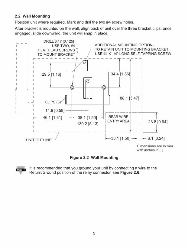
2.2 Wall Mounting
Position unit where required. Mark and drill the two #4 screw holes.
After bracket is mounted on the wall, align back of unit over the three bracket clips, onceengaged, slide downward, the unit will snap in place.
Figure 2.2 Wall Mounting
It is recommended that you ground your unit by connecting a wire to theReturn/Ground position of the relay connector, see Figure 2.6.
14.9 [0.59]
46.1 [1.81] 38.1 [1.50]
130.2 [5.13]
38.1 [1.50] 6.1 [0.24]
23.8 [0.94]
88.1 [3.47]
34.4 [1.36]
REAR WIREENTRY AREA
ADDITIONAL MOUNTING OPTION-TO RETAIN UNIT TO MOUNTING BRACKETUSE #4 X 1/4" LONG SELF-TAPPING SCREW
DRILL 3.17 [0.125] USE TWO, #4
FLAT HEAD SCREWSTO MOUNT BRACKET
UNIT OUTLINE
CLIPS (3)
29.5 [1.16]
Dimensions are in mmwith inches in [ ].

6
2.3 Parts of the iServer Unit
Figure 2.3 Parts of the iServer Unit
Table 2.1 Parts of iServer Unit
ETHERNET RJ45 interface for 10/100BASE-T connection.
RESET Button: Momentary (Push and Release) resets power on unit; Push and Hold for10 seconds to reset unit to factory defaults and reset power.
100 BASE-T LED (Green) On: Indicates 100 Mbps; LED Off: Indicates 10 Mbps.
LINK/ACT LED (Green) On/Blinking: Indicates good network link and network activities (receiving or sending packets).
DHCP LED (Yellow): When DHCP is enabled, once the iServer receives the IP parameters from the DHCP server this LED will turn Solid yellow.
RECORDING LED (Green) Blinking Fast: Indicates that the unit is recording. LED Blinking: during back-up battery operation according to sampling rate, or recording intervalif recording is ON.
°C/°F Button: Press to change LCD display units of measurement between °C and °F. Press and Hold along with TIME/IP button during power-on, this will enable DHCP mode.
TIME/IP Button: Press repeatedly to change LCD display from: 1) Date and Time;2) iServer’s IP address; 3) Temperature and Humidity. Press and Hold along with °C/°F button during power up, this will enable DHCP mode.
C/ F TIME/IP BKLT
RS
T
ETHERNET9-12 Vdc
dc Power Input
SD FlashMemoryCardStandbyButton
CoverScrew(2 plcs)
SD FlashMemoryCard
32 Digit LCD Display
Buttons
iServer RJ45 interface
1 8
iServer Reset Button
DetachableTemp + RH
Probe
9Vdc Battery(under cover)
iServer LEDs
Bottom Wire EntryI/O Connectors
Removable PlugConnector for
Input and Outputs(under cover)
1 6 1 4
TOP VIEW
+-
100 BASE-TLINK/ACTDHCPRECORDING
ST
BY
The 9V battery is theback-up power for therecording function only.
Warning:
The standardright angle
probe is ESDSensitive

7
2.3 Parts of the iServer Unit (continued)
BKLT Button: Push and Hold to display Backlight on LCD when it is running on the back-up battery (backlight is always on while running on the ac adapter).
STBY Button: 1) Stops the recording; 2) Press before ejecting Flash Card.NOTE: display will show “Safe to Eject SD” after button has been pressed.
2.4 Disassembly Instruction
You may need to open the unit for one of the following reasons: • To wire relay and I/O connector. (Refer to Figure 2.6)• To connect or replace the battery.
Disconnect the power supply before proceeding.
• Make sure the flash memory card is fully inserted (or removed), before removing the cover.• Remove probe from handle clip (if needed).
Remove cover, by removing 2 mounting screws on each side.
Figure 2.4 Opening the Unit
MOUNTINGSCREWS (2)
SD FLASHCARD
COVER
RELAYCONNECTOR
TRAY
I/O CONTACTCONNECTOR ETHERNET &
DC POWERCONNECTORS
BATTERYLOCATION
TEMP/HUMIDITY
PROBE
Press STBYbefore ejectingFlash Card.NOTE: display willshow “Safe toEject SD” afterbutton has beenpressed.

8
2.4.1 Battery Installation
Figure 2.5 Battery Installation
2.5 Network Communication Interfaces
2.5.1 10/100 BASE-T RJ-45 Pinout
The 10/100BASE-T Ethernet networksystem is used in the iServer fornetwork connectivity. The 10 Mbps or100 Mbps twisted-pair Ethernet systemoperates over two pairs of wires. Onepair is used for receiving data signalsand the other pair is used fortransmitting data signals. This meansthat four pins of the eight-pin connectorare used.
For CE compliance at 100 Mbps: use shielded cable, opposite end of cable mustbe grounded.
2.5.2 Connecting iServer to PC/Hub/Switch/Router
The iServer’s Ethernet interface can automatically detect the Rx and Tx lines on atwisted pair Ethernet cable (MDI/MDIX Auto Cross). Therefore, to connect an iServer to aPC/Hub/Switch/Router, either a straight-through or a cross-over cable can be used.
On certain devices (like iServer), it is possible for the hardware to automaticallycorrect errors in cable selection, making the distinction between a “straight-through” cable and a “cross-over” cable unimportant. This capability is known as“Auto MDI/MDIX”.
KEEP INSULATOR COVER ON BATTERY CLIPWHEN BATTERY IS NOTBEING USED
TRAY REMOVE BATTERY CLIPINSULATOR COVER ANDSTORE AGAINST BATTERYWHEN BATTERY IS BEING USED.
INSULATOR COVER
9 VDC BATTERY
Pin Name Description1 +Tx + Transmit Data2 -Tx - Transmit Data3 +RX + Receive Data4 N/C Not Connected5 N/C Not Connected6 -Rx - Receive Data7 N/C Not Connected8 N/C Not Connected
Figure 2.6 RJ45 Pinout
9
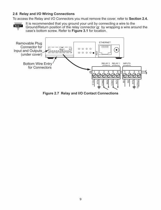
2.6 Relay and I/O Wiring Connections
To access the Relay and I/O Connectors you must remove the cover, refer to Section 2.4.
It is recommended that you ground your unit by connecting a wire to theGround/Return position of the relay connector or by wrapping a wire around thecase’s bottom screw. Refer to Figure 3.1 for location.
Figure 2.7 Relay and I/O Contact Connections

PART 3NETWORK CONFIGURATION3.1 Network Protocols
The iServer can be connected to an Ethernet network communicating through standardIP protocols including TCP, UDP, SNMP, SMTP, ARP, HTTP (WEB access), DNS, DHCP,ICMP, SNTP, and Telnet.
3.2 Ethernet (MAC) Address
MAC (Media Access Control) address is a unique hardware number for Ethernet deviceslike computers, network switches, print servers, etc. When you're connected to anEthernet LAN using a computer you can see a table of IP addresses called “ARP table”stored on that computer. The ARP table relates IP addresses of devices on a network totheir corresponding MAC addresses. The MAC address can be found on a labelattached to your Ethernet device and it contains 6 bytes (12 characters) of hexadecimalnumbers XX:XX:XX:XX:XX:XX hex
For example: 0A:0C:3D:0B:0A:0B
Remove the small label with the default IP address of 192.168.1.200 and therewill be room to put your IP address. See Figure 3.1
Figure 3.1 Labeling
FIRMWAREVERSION #
MAC ADDRESS LABELIN HEX CODE
REMOVE DEFAULT IP ADDRESS LABELAND PUT NEW CUSTOMER'S IP ADDRESS
1
SCREW FORGROUNDING UNIT
1010

11
3.3 DHCP
DHCP, Dynamic Host Configuration Protocol, enables computers and network devices toreceive their IP configurations from a DHCP server.
If DHCP is enabled on your iServer, as soon as the iServer that is connected to thenetwork is powered on, there will be an exchange of information between the iServer andthe DHCP server. As a result, the DHCP server will assign an IP address, a Gatewayaddress, a Subnet Mask, and a DNS address to the iServer. Note that the DHCP servermust be correctly configured to make such assignments.
If fixed or static IP address is desired, the DHCP function must be disabled.
The iServer is shipped with DHCP disabled (factory default).
The DHCP can be enabled by accessing the iServer’s web server and selecting Networkmenu (refer to Section 4.4.2) or by pressing and holding the two front buttons °C/°F andTIME/IP during power-on (refer to Section 2.3).
It’s very important to communicate with the network administrator in order tounderstand DHCP and its existing configurations on the host server beforeenabling DHCP on the iServer.
The iServer is shipped with a default static IP address of 192.168.1.200 andSubnet Mask of 255.255.255.0.
3.4 DNS
DNS, Domain Name System, enables computers and devices to be recognized over anetwork based on a specific name instead of IP addresses.
For example, instead of having to use http://192.168.1.200 (IP address), you would usehttp://isdb870 or any name up to sixteen alphanumeric characters defined as a HostName in the iServer’s web server.
The default Host Name for an iServer is "isd" followed by the last four digits of the MACaddress of that iServer unit.
On Windows servers where DHCP and DNS are separate functions it is veryimportant to configure the DHCP server to communicate with DNS in order forthe iServer’s Host Name to correctly respond. If you cannot access the iServerusing its Host Name, please contact your network administrator to make sureDHCP and DNS servers are linked together.
If DNS server address is setup, all Host Names reported during weblink configuration(i.e. SMTP server IP, SNTP server IP, SNMP trap server IP, etc.) will be translated into IPaddresses.
3.5 IP Address
Every active device connected to the TCP/IP network must have a unique IP address.This IP address is used to build a connection to the iServer.
All network devices like computers that use TCP/IP protocol to communicate with eachother should have a unique 32-bit address called IP address. The IP address is dividedinto two portions, the network ID and the host ID. For instance, every computer on thesame network uses the same network ID. At the same time, all of them have differenthost IDs. For more details about the IP address see Appendix B.
12
3.6 Port Number
All TCP connections are defined by the IP address and a port number. A port number isan internal address that provides a TCP/IP interface between an application software ona computer and a device on the network or between two devices on the network.
There are two default TCP port (socket) numbers assigned to the iServer:
1) Port 2000: Once a TCP connection is made to the iServer using port 2000 or anyport number that is configured on the iServer for Local Port (see Network menu,Section 4.4.2), the iServer can then be polled for variables like temperature,humidity, etc. using commands. For the list of commands see Section 4.9.1.
2) Port 2002: This port is the iServer’s network console port for reading or changingthe settings within the iServer. For the list of settings refer to Section 4.8.1. For bothof the above cases, for example, a Telnet application can be used.
PART 4OPERATIONSDepending on user’s preference and network setup, the iServer can be configured inseveral ways:
Using the latest versions of Web browsers like Internet Explorer, Firefox, Opera, orSafari (iPhone) the iServer’s Web server can be accessed, see Section 4.2.
It can also be configured using a TCP connection to port 2002 using a command lineinterface, see Section 4.8.1.
The iCONNECT Configuration Software can also be used to find and configure theiServer over the Ethernet, see Section 4.1.2.
Before you configure the iServer, you will need to assign an IP address to theunit. Refer to Section 4.1.1, 4.1.2 or 4.1.3.
4.1 IP Address Assignment
4.1.1 DHCP (Method 1)
The DHCP server will assign an IP address, see Section 3.3.
4.1.2 ARP HTTPget Commands (Method 2)
You can download the HTTPget program from our web site to use it for this section.
1. From the Command line (DOS prompt) where you keep the HTTPget.exe file, type thefollowing:
arp -s 128.100.101.76 00-03-34-00-b8-70 press the <Enter> key
128.100.101.76, for example, is the IP address that you want to assign to your iServerand 00-03-34-00-b8-70 is the MAC address of your iServer labeled on the bottom of theunit.
2. From the same prompt, type the following HTTPget command:
httpget -r -S “00000000” 128.100.101.76:1 press the <Enter> key
00000000 is the default ADMINISTRATOR password in your iServer unit and128.100.101.76:1 is the IP address that your iServer will accept on TCP port 1. At thispoint, you have successfully assigned 128.100.101.76 IP address to your iServer.
Continued on the following page.
13
4.1.2 ARP HTTPget Commands (Method 2) (continued)
The above IP address of 128.100.101.76 is an example to show how thesecommands work. To get a valid IP address on your network you need to consultwith your IT department.
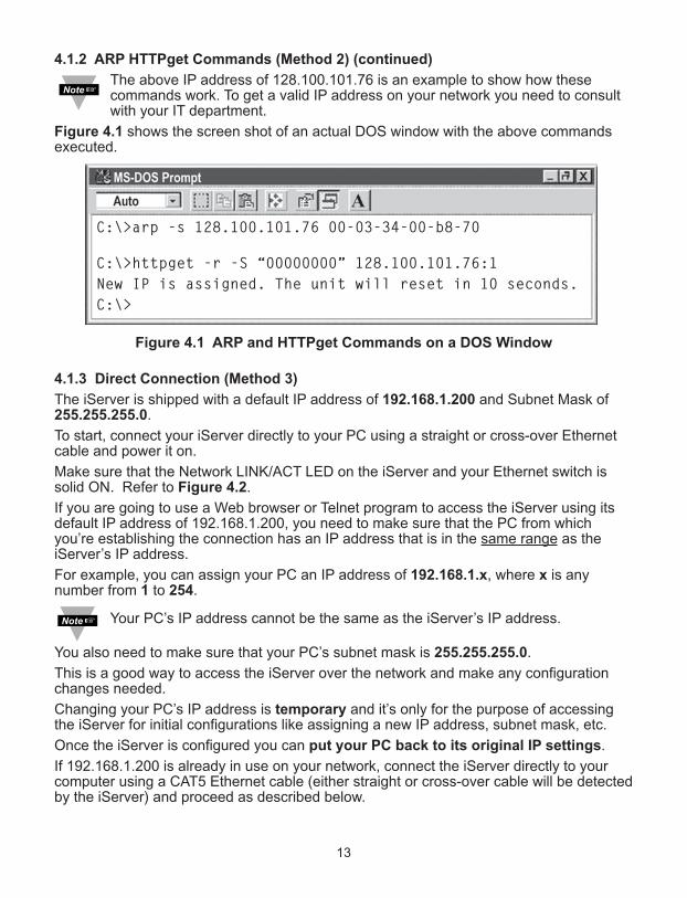
Figure 4.1 shows the screen shot of an actual DOS window with the above commandsexecuted.
Figure 4.1 ARP and HTTPget Commands on a DOS Window
4.1.3 Direct Connection (Method 3)
The iServer is shipped with a default IP address of 192.168.1.200 and Subnet Mask of255.255.255.0.
To start, connect your iServer directly to your PC using a straight or cross-over Ethernetcable and power it on.
Make sure that the Network LINK/ACT LED on the iServer and your Ethernet switch issolid ON. Refer to Figure 4.2.
If you are going to use a Web browser or Telnet program to access the iServer using itsdefault IP address of 192.168.1.200, you need to make sure that the PC from whichyou’re establishing the connection has an IP address that is in the same range as theiServer’s IP address.
For example, you can assign your PC an IP address of 192.168.1.x, where x is anynumber from 1 to 254.
Your PC’s IP address cannot be the same as the iServer’s IP address.
You also need to make sure that your PC’s subnet mask is 255.255.255.0.
This is a good way to access the iServer over the network and make any configurationchanges needed.
Changing your PC’s IP address is temporary and it’s only for the purpose of accessingthe iServer for initial configurations like assigning a new IP address, subnet mask, etc.
Once the iServer is configured you can put your PC back to its original IP settings.
If 192.168.1.200 is already in use on your network, connect the iServer directly to yourcomputer using a CAT5 Ethernet cable (either straight or cross-over cable will be detectedby the iServer) and proceed as described below.
C:\>arp -s 128.100.101.76 00-03-34-00-b8-70
C:\>httpget -r -S “00000000” 128.100.101.76:1
New IP is assigned. The unit will reset in 10 seconds.
C:\>

14
4.1.3 Direct Connection (Method 3) (continued)
Figure 4.2 Connecting Computer Directly to iServer
Figure 4.3 Network Connections
Figure 4.4 Local Area Connection
100 BASE-TLINK / ACTDHCPRECORDING
Ethernet Cable
After connecting the iServer to computer, power it on.LINK/ACT LED should be SOLID green
Computer’s Ethernet Port (RJ45 connection)
Plug in thePower Adapter
iServer with default IP address
of 192.168.1.200
1) Click on your Windows “Start” menu and select“Control Panel” from the list options.
Double click on the “Network Connections” icon
2) You now have “Network Connections”window opened.
The “Local Area Connection” icon hasall the settings for your ethernetconnection.
Double click on this icon.
4.1.3 Direct Connection (Method 3) (continued)
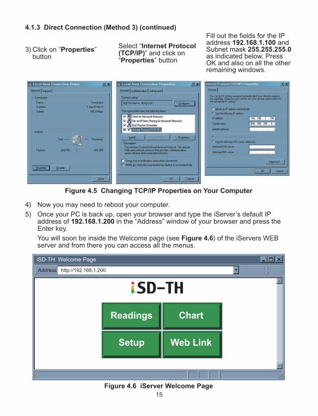
Figure 4.5 Changing TCP/IP Properties on Your Computer
4) Now you may need to reboot your computer.
5) Once your PC is back up, open your browser and type the iServer’s default IPaddress of 192.168.1.200 in the “Address” window of your browser and press theEnter key.
You will soon be inside the Welcome page (see Figure 4.6) of the iServers WEBserver and from there you can access all the menus.
Figure 4.6 iServer Welcome Page
http://192.168.1.200Address
iSD-TH Welcome Page
Readings Chart
Setup Web Link
15
3) Click on “Properties”button
Select “Internet Protocol(TCP/IP)” and click on“Properties” button
Fill out the fields for the IPaddress 192.168.1.100 andSubnet mask 255.255.255.0as indicated below. PressOK and also on all the otherremaining windows.
16
4.1.3 Direct Connection (Method 3) (continued)
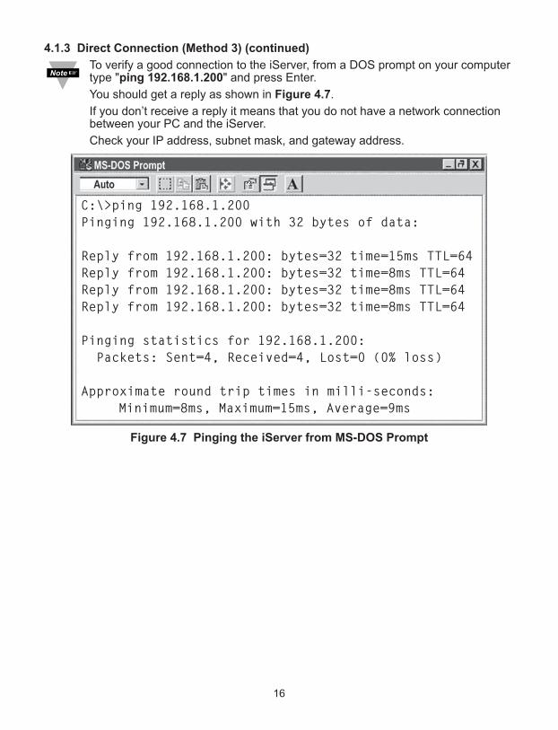
To verify a good connection to the iServer, from a DOS prompt on your computertype "ping 192.168.1.200" and press Enter.
You should get a reply as shown in Figure 4.7.
If you don’t receive a reply it means that you do not have a network connectionbetween your PC and the iServer.
Check your IP address, subnet mask, and gateway address.
Figure 4.7 Pinging the iServer from MS-DOS Prompt
C:\>ping 192.168.1.200
Pinging 192.168.1.200 with 32 bytes of data:
Reply from 192.168.1.200: bytes=32 time=15ms TTL=64
Reply from 192.168.1.200: bytes=32 time=8ms TTL=64
Reply from 192.168.1.200: bytes=32 time=8ms TTL=64
Reply from 192.168.1.200: bytes=32 time=8ms TTL=64
Pinging statistics for 192.168.1.200:
Packets: Sent=4, Received=4, Lost=0 (0% loss)
Approximate round trip times in milli-seconds:
Minimum=8ms, Maximum=15ms, Average=9ms
17
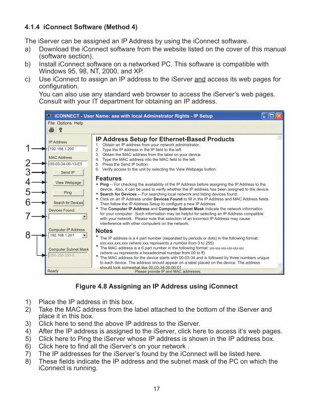
4.1.4 iConnect Software (Method 4)
The iServer can be assigned an IP Address by using the iConnect software.a) Download the iConnect software from the website listed on the cover of this manual
(software section).b) Install iConnect software on a networked PC. This software is compatible with
Windows 95, 98, NT, 2000, and XP. c) Use iConnect to assign an IP address to the iServer and access its web pages for
configuration. You can also use any standard web browser to access the iServer’s web pages.Consult with your IT department for obtaining an IP address.
Figure 4.8 Assigning an IP Address using iConnect
1) Place the IP address in this box.2) Take the MAC address from the label attached to the bottom of the iServer and
place it in this box.3) Click here to send the above IP address to the iServer.4) After the IP address is assigned to the iServer, click here to access it’s web pages.5) Click here to Ping the iServer whose IP address is shown in the IP address box.6) Click here to find all the iServer’s on your network .7) The IP addresses for the iServer’s found by the iConnect will be listed here.8) These fields indicate the IP address and the subnet mask of the PC on which the
iConnect is running.

4.1.4 iConnect Software (Method 4) (continued)
d) To access the iServer for Configuration:
Click on the “View Webpage” button, you will access the iServer’s welcome page.
To take advantage of the iServer’s full capability use any standard web browser toaccess the iServer’s web pages as described in Section 4.2.
Figure 4.9 Accessing the iServer’s using iConnect
18

19
4.2 Access and Configuration Using a Web Browser• Start your web browser.• In the URL field, type http://192.168.1.200 (iServer’s default IP address).• The Welcome Page, will be displayed.
Figure 4.10 iServer Welcome Page
In order to access the iServer’s web pages, users may be prompted for apassword, as shown below.
4.3 LOGIN and ADMINISTRATOR Passwords
Figure 4.11 LOGIN and ADMINISTRATOR Passwords
There are 2 different access levels:
1. LOGIN Password is required to access the iServer’s Readings, Chart, and Web Linkpages unless it’s disabled. The default password is 12345678.
2. ADMINISTRATOR Password is required to access the iServer’s Setup menu unlessit’s disabled. The default password is 00000000.
Refer to Section 4.4.5 for Password setup.
http://192.168.1.200Address
iSD-TH Welcome Page
Readings Chart
Setup Web Link
http://192.168.1.200Address
Login
Readings Chart Web Link Setup
Password: OK
LOGIN
http://192.168.1.200Address
Administrator Login
Readings Chart Web Link Setup
Password: OK
ADMINISTRATOR

4.4 Setup
Clicking the Setup button on the Welcome page (see Figure 4.10) will provide access tothe Menu Panel (see Figure 4.12).
Using this Panel you can configure the iServer entirely.
4.4.1 Overview
Once the Administrator password is entered, the Overview page will appear whichprovides a summary of important parameters within the iServer.
All the fields are read-only.
Figure 4.12 Overview
http://192.168.1.200Address
Overview
Readings Chart Web Link Setup
Overview
NetworkConfigurationManagementSecurityRecordingSystemDiagnosticsLog Out
ModelFirmware VersionDHCPMAC AddressIP AddressSubnet MaskGateway AddressHostnameEthernet PortWeb Server PortRecordingUptime
x.xDisabled00:03:34:00:b8:70192.168.1.200255.255.255.00.0.0.0 isdb870Auto80OFF
1 day, 00:00:00 hh:mm:ss
Men
u B
arM
enu
Pan
el
iSD-TH
20

4.4.2 Network
This menu provides network configurations including IP parameters and Ethernetinterface options. Fields are described below.
4.4.2.1 IP Configuration
Figure 4.13 Network: IP Configuration
DHCP – If the box is checked the iServer will dynamically request an IP address, asubnet mask, a gateway address, and a DNS address from the DHCP server. By defaultthe DHCP option is disabled. For more information about DHCP, see Section 3.3.
DHCP can be enabled by pressing and holding the two front buttons ºC/ºF andTIME/IP during power-on (refer to Section 2.3).
MAC Address – This Indicates the hardware address of the iServer and it is non-configurable. For more information about MAC Address, see Section 3.2.
IP Address – This indicates the IP address of the iServer. The iServer’s default IPaddress is 192.168.1.200. When DHCP is enabled this field will be dimmed. Consult withyour IT department for obtaining an IP address.
Subnet Mask – It’s a 32-bit number that is used to determine which part of the IPaddress is the network portion and which part is the host portion. When DHCP is enabledthis field will be dimmed. The iServer’s default Subnet Mask is 255.255.255.0. Consultwith your IT department for obtaining a subnet mask.
http://192.168.1.200Address
Network
Readings Chart Web Link Setup
OverviewNetwork
ConfigurationManagementSecurityRecordingSystemDiagnosticsLog Out
Save Changes Reset
DHCP
MAC Address
IP Address
Subnet Mask
Gateway Address
DNS Address
Host Name
Protocol
Local Port
Web Server Port
Web Link Title
Web Link Address
192.168.1.200
255.255.255.0
0.0.0.0
0.0.0.0
isdb870
TCP
2000
80
WebLink
www.123abc.com
IP Configuration Ethernet Port
00:03:34:00:b8:70
21

4.4.2.1 IP Configuration (continued)
Gateway Address – This points to the router that forwards traffic to a destinationaddress outside of the subnet on which the iServer resides. This is the IP address of therouter which functions as a gateway. When DHCP is enabled this field will be dimmed.The iServer’s default Gateway address is 0.0.0.0. Consult with your IT department forobtaining a gateway address.
DNS Address – In order to use the hostname to access the iServer, the DNS server onyour network must be configured, refer to Section 3.4. iServer plays the role of a DNSclient, in the sense that the iServer will actively query the DNS server for the IP addressassociated with a particular domain name. When DHCP is enabled this field will bedimmed. The iServer’s default DNS address is 0.0.0.0. Consult with your IT departmentfor obtaining a DNS address.
Host Name – If DHCP is enabled, the iServer will send this name to the DHCP server.This name is used so that the iServer can be accessed based on a specific nameinstead of an IP address. For example, instead of using http://192.168.1.200 (IPaddress), you would use http://isdb870 or any name up to sixteen (16) alphanumericcharacters. The default Host Name for an iServer is "isd" followed by the last four digitsof the MAC address of that particular iServer.
On Windows servers where the DHCP and DNS are separate functions it’s veryimportant to configure the DHCP server to communicate with the DNS in orderfor the iServer’s Host Name to correctly respond. If you cannot access theiServer using its Host Name, please contact your network administrator to makesure the DHCP and DNS servers are linked together.
Protocol – It’s the network protocol the iServer communicates with the EthernetNetwork. Options are TCP and UDP. The default is TCP.
Local Port – The default port is 2000. Refer to Section 3.6.
Web Server Port – The default port is 80. This is the primary port number for the HTTPprotocol used for communication between internet browsers and web sites/web servers.Web servers open this port then listen for incoming connections from web browsers.Similarly, when a web browser is given an IP address (like the iServer’s IP address), itassumes that the iServer’s web server is listening for connections on port 80. If this portis changed to anything but 80 then on the browser the new port number must beindicated with a colon (:) after the IP address. For example, if the Web Server Port ischanged to 500, you will then need to type http://192.168.1.200:500 on the browser toaccess the iServer’s web server.
One of the applications where the Web Server Port number may need to changeis when users want to access the iServer’s web server from outside the localarea network (i.e. Internet). By setting up “Port Forwarding” inside a router thatis the gateway to that local area network this task can be accomplished. “PortForwarding” technique uses the Web Server Port number to forward the Internetconnection to the iServer on the LAN.
Web Link Title – This is a text field that appears on the button on the iServer’s Web LinkPage, refer to Section 4.7. This can describe the Web Link Address assigned below.
Web Link Address – This provides a link to any TCP/IP node on the network or anyWeb link on the Internet. Examples would be www.123abc.com or if you have a devicewith an embedded Web server (just like the iServer) once you enter its IP address in thisfield and click on the Web Link button on the iServer’s Welcome page you'll be able toaccess your device using the same browser interface.
22

4.4.2.2 Ethernet Port
Figure 4.14 Network: Ethernet Configuration
Auto-Negotiation – It is the link, in terms of speed and duplex, between the iServer andanother Ethernet device like an Ethernet switch.
If Auto-Negotiation box is checked, the iServer will auto-negotiate the speed and duplexwith the attached Ethernet device. If any of the other options are selected, the speed andduplex will be fixed.
It’s important to have the same Ethernet port configuration on the iServer and theattached Ethernet device. If iServer cannot auto-negotiate with the attached Ethernetnode it will default to 10 Mbps and Half-Duplex. Once Auto-Negotiation is checked, otherfields under this category will be dimmed. By default the Auto-Negotiation is checked.
If the iServer detects the link to be 100 Mbps the 100 BASE-T LED will be solidgreen.
4.4.3 Configuration
This menu provides configurations for the real-time clock, server parameters, sensors,and alarm relays settings. Fields are described below.
4.4.3.1 Date and Time
Current Date – This field indicates the iServer’s real time clock date. The format isyyyy/mm/dd. When there is no date defined, the iServer will be defaulted to 2099/01/01and be shown in red to alert you that it has not yet been set..
Current Time – This field indicates the iServer’s real time clock time. The format ismilitary time (24-hour) and it is entered as hh:mm:ss.
Change Date and Time – By clicking on this option the real data and time can be entered.
http://192.168.1.200Address
Ethernet Port
Readings Chart Web Link Setup
OverviewNetwork
ConfigurationManagementSecurityRecordingSystemDiagnosticsLog Out
Save Changes Reset
IP Configuration Ethernet Port
Auto-Negotiation
Speed
Duplex
100 Mbps
Full
10 Mbps
Half
23
4.4.3.1 Data and Time (continued)
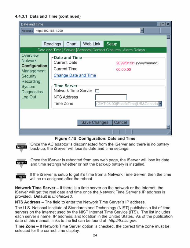
Figure 4.15 Configuration: Date and Time
Once the AC adaptor is disconnected from the iServer and there is no batteryback-up, the iServer will lose its date and time settings.
Once the iServer is rebooted from any web page, the iServer will lose its dateand time settings whether or not the back-up battery is installed.
If the iServer is setup to get it’s time from a Network Time Server, then the timewill be re-assigned after the reboot.
Network Time Server – If there is a time server on the network or the Internet, theiServer will get the real date and time once the Network Time Server’s IP address isprovided. Default is unchecked.
NTS Address – The field to enter the Network Time Server’s IP address.
The U.S. National Institute of Standards and Technology (NIST) publishes a list of timeservers on the Internet used by the NIST Internet Time Service (ITS). The list includeseach server’s name, IP address, and location in the United States. As of the publicationdate of this manual, links to the list can be found at http://tf.nist.gov.Time Zone – If Network Time Server option is checked, the correct time zone must beselected for the correct time display.
http://192.168.1.200Address
Date and Time
Readings Chart Web Link Setup
Save Changes Cancel
Current Date
Current Time
Change Date and Time
Date and Time
Network Time Server
NTS Address
Time Zone (GMT-08:00)Pacific Time(US&Canada)
Time Server
SensorsServer Alarm RelaysContact ClosuresDate and Time
OverviewNetworkConfiguration
ManagementSecurityRecordingSystemDiagnosticsLog Out
2099/01/01 (yyyy/mm/dd)
00:00:00
24

4.4.3.2 Server
Figure 4.16 Configuration Menu: Server
Server Type – Options are Command and Continuous. If Command is selected the iServer will respond to commands sent from a network host(for the list of commands refer to Section 4.9.1). If Continuous is selected the iServer will send temperature, humidity, and dewpointvalues once every time amount selected in the Interval box. The Command and Continuous modes operate when a network host opens a TCPconnection to the iServer’s IP address with port 2000.In UDP Command mode, iServer will respond back with a UDP packet (to the _ address andport) if a host application sends a UDP command to iServer’s IP address with port 2000.
In UDP Continuous mode, iServer starts sending continuous data if a host applicationsends a trigger or UDP packet to iServer’s IP address with port 2000.
Interval – This is the time interval (in seconds) between each data transmission whenthe iServer is in Continuous mode. The default value is set to 5 seconds and theminimum is 2 seconds.Time Stamp – If checked, the iServer will stamp the data with date and time beforesending it out to a network host. This will apply to Command and Continuous modes.Default is unchecked.Disconnect After Data Sent – If checked, once the iServer responds back with data, theiServer will close the TCP connection that had been made from the network host.This feature should be used if data acquisition software expects data to be ended byclosing TCP connection from the client.
http://192.168.1.200Address
Server
Readings Chart Web Link Setup
Save Changes Reset
Server Type
Interval
Disconnect After Data Sent
Time Stamp
Command
5 secs
Server
SensorsServer Alarm RelaysContact ClosuresDate and Time
OverviewNetworkConfiguration
ManagementSecurityRecordingSystemDiagnosticsLog Out
25

26
4.4.3.3 Sensors
This page is where the Sensor Parameters are defined. Reading 1 is for Temperature,Reading 2 is for Humidity, and Reading 3 is for Dewpoint.
Figure 4.17 Configuration Menu: Sensors
Description – This can be a name for the sensor or where the sensor is located. Thisfield is text only and can have up to 16 alphanumeric characters. This description willappear wherever Reading 1, 2 or 3 is displayed on the web server.Unit – This is the unit of measurement for temperature. It can be either C for Celsius or Ffor Fahrenheit.
Once the unit is selected, either C or F, it will be a global change throughout theweb server, as well as on the LCD display. If you use the front C/F buttons tochange the unit of temperature it will have no affect on the web pages.
Display – If checked the variable (i.e. Temperature1) will be displayed on the Readingsand Chart applets as well as data transmission in Continuous mode (see Server TypeSection 4.4.3.2). The default is checked.
http://192.168.1.200Address
Sensors
Readings Chart Web Link Setup
OverviewNetworkConfiguration
ManagementSecurityRecordingSystemDiagnosticsLog Out
Save Changes Reset
SensorsServer Alarm RelaysContact ClosuresDate and Time
Description
End Character 0x
CTemperature 1Reading 1
Unit Display
Data Format
OffsetOffset Adjust by
Offset Adjust by
0D
Description
End Character 0x
HumidityReading 2
0D
Description
End Character 0x
DewpointReading 3
0D
T000.0C
%Unit
Data Format H00.0%
CUnit
Data Format D000.0C
Samplng Rate
One Sample per 10 seconds
0.0
Reading Low 0.0
Reading High 100.0
Ref. Low 0.0
Ref. High 100.0
Display
Offset
Display
0.0
Reading Low 0.0
Reading High 100.0
Ref. Low 0.0
Ref. High 100.0

27
4.4.3.3 Sensors (continued)
End Character – The iServer can attach a character (in Hex) to the end of temperaturedata packet. This will apply to either Continuous or Command mode. If 00 is enteredthere will be no character attached. The default is 0D (Hex representation of <CR>).
Data Format – This indicates the format of the temperature reading being displayed on anetwork host when Continuous transmission is used (see Server Type Section 4.4.3.2).
Adjust by – If it’s determined that the reading is slightly off this field can be used toadjust the reading. The options are Offset and Scale & Offset. Using the Offset method you can manually assign a numerical value to adjust thereading. For example if the actual reading is 55 where it should be 54 you can enter -1 inthe Offset field.
The Scale & Offset method uses two points to adjust the reading within the entiretemperature range. For example, if at the lower point the actual reading is 10 where itshould be 12 and at the higher point the actual reading is 200 where it should 195, hereis how the numbers are entered.
The adjusting numbers can be positive or negative with one decimal point.
The adjusting values must be assigned after the unit of temperature (C or F) isselected. If the unit of temperature is changed, you must re-adjust the values fora correct result.
Sampling Rate – This determines the rate in which the iServer polls the probe fortemperature and humidity values.
The options are 1, 10, and 60 seconds. The default is set for 10 seconds.
The higher the sampling rate, the more accurate data is transmitted by the probe.
Reading Low 10.0
Reading High 200.0
Ref. Low 12.0
Ref. High 195.0

28
4.4.3.4 Contact Closure
Figure 4.18 Configuration Menu: Contact Closures
Contact 1 & 2 – This configures the first and second Contact Closures on the iServer.For wiring and pin-outs see Section 2.6. The options for Contact 1 & 2 are Disable,Normally Open, and Normally Close. Default is Disable.
Normally Open and Normally Close are the initial states of the Contact Closure. Forexample, if it’s set for Normally Open, the iServer will display NORMAL status as long asthe contact is open. Once the contact is closed the iServer will change the status toACTIVE.
If Disable option is selected the Contact Closures will be inoperable.
Description – This is a text-only field and can take up to 16 alphanumeric characters.This can be the name of a device connected to the Contact (i.e. Alarm) or the location.This name is displayed on the Readings webpage and responded to Command andContinuous mode connections. Defaults are Contact In1 and Contact In2.
End Character – This means that the iServer will send a character (in Hex) aftersending the state of the Contact Closure in Continuous or Command mode. Default is 0D(Hex representation of <CR>).
Display – If checked the status of Contacts will be displayed on the Readings webpageand responded to Command and Continuous mode connections. Default is unchecked.
Output – The options are Active High and Active Low. The Output will be High or Low ifthe Contact 1 or Contact 2 status is changed. Default is Active Low.
http://192.168.1.200Address
Contact Closures
Readings Chart Web Link Setup
Save Changes Reset
Contact 1
Description
End Character 0x
Display
Disable
Contact In1
0D
Contact 2
Description
End Character 0x
Display
Disable
Contact In2
0D
Type Unlatch
Clear Latch
Record all alarm events on the flash memory Retrieve
SensorsServer Alarm RelaysContact ClosuresDate and Time
OverviewNetworkConfiguration
ManagementSecurityRecordingSystemDiagnosticsLog Out
Contacts
Output
End Character 0x
Display
Active Low
0D
Output

29
4.4.3.4 Contact Closure (continued)
End Character – This means that the iServer will send a character (in Hex) after sendingthe state of the Output in Continuous or Command mode. Default is 0D (Hexrepresentation of <CR>).
Type – The options are Unlatch and Latch. Default is Unlatch.
If it’s set to Unlatch, once the Contact is back to NORMAL the Output will automaticallychange to its original state.
If it’s set to Latch, once the Contact is back to NORMAL the Output will remainunchanged until the user clicks on the Clear Latch button.
Display – If checked the status of the Output will be displayed on the Readings webpageand responded to Command and Continuous mode connections. Default is unchecked.
Record contact events on the flash memory – If checked the Output status withstamped date and time will be recorded into an ASCII file on the flash memory card. Byclicking the Retrieve button the file will be open. Default is unchecked.
4.4.3.5 Alarm Relays
This section would allow the two relays on the iServer to be configured as needed. Forphysical connections and pin-outs refer to Section 2.6.
Figure 4.19 Configuration Menu: Alarm Relays
Relay 1 and Relay 2 – This configures the first and second relays on the iServer. Theoptions for each are temperature, humidity, and dew point.This means that both Relays can be set for temperature or both Relays can be set forhumidity, or one can be set for humidity and one for temperature.
http://192.168.1.200Address
Alarm Relays
Readings Chart Web Link Setup
Save Changes Reset
Relay 1
Description
Status
Type
Set Point High
Set Point Low
End Character 0x
Display
Temperature
Alarm Relay 1
Disable
Unlatch
Clear Latch
0.0
0.0
0D
Relay 2
Description
Status
Type
Set Point High
Set Point Low
End Character 0x
Display
Humidity
Alarm Relay 2
Disable
Unlatch
Clear Latch
0.0
0.0
0D
Record all alarm events on the flash memory Retrieve
SensorsServer Alarm RelaysContact ClosuresDate and Time
OverviewNetworkConfiguration
ManagementSecurityRecordingSystemDiagnosticsLog Out
30
4.4.3.5 Alarm Relays (continued)
Description – This is a text field for naming the device connected to the relay or it couldbe the location where the device is installed. This field can take up to 16 alphanumericcharacters. This name will be displayed anywhere on the web pages associated withalarm relays; for example the Readings applet.
Defaults are Alarm Relay1 and Alarm Relay2.
Status – The options are Disable, Low, High, and Low or High. The default is Disable.
If Low is selected Set Point Low must be given a value and once the sensor reading fallsbelow that value the relay will change status.
If High is selected Set Point High must be given a value and once the sensor readingrises above that value the relay will change status.
If Low or High is selected Set Point Low and High must be given values and relay statuswill change once the sensor reading is outside that range.
If Disable is selected relays will be deactivated.
Alarm status with the associated set point will be shown on the chart applet as well.
Type – The options are Unlatch and Latch. The default is Unlatch.
If Unlatch is selected and the relay is activated, once the sensor reading goes backwithin the Set Point range, the alarm will be deactivated automatically.
If Latch is selected, once the sensor reading goes back within the Set Point range, therelay will remain active until the user clears it by clicking on the Clear Latch button.
Set Point High – This is the field for the upper Set Point.
Set Point Low – This is the field for the lower Set Point.
End Character – This is the character (in Hex) that the iServer will send along with thealarm status.
This applies to either Continuous or Command mode described on the Server page,under the Configuration menu (Section 4.4.3.2).
The default is 0D meaning a Carriage Return character will be sent after the value.
Display – This would indicate whether to display the status of the alarm relays on theReadings applet as well as the TCP Command and Continuous modes, and any otherrelated fields.
The default is unchecked.
Record all alarm events on the flash memory – If checked, all the alarm events withstamped date and time will be recorded on the flash memory card.
By pressing the Retrieve button the ASCII log file will be opened.
The default is unchecked.
Using the web server, the log file can be retrieved if the file size is 32 KB orsmaller. For a larger file size you must use a flash card reader to open the logfile. Refer to Section 4.10.

4.4.4 Management
This page provides the iServer’s email, SNMP and alarm settings. SNMP (SimpleNetwork Management Protocol) is the protocol used by network management systems tocommunicate with network devices that respond to SNMP connections for the purpose ofproblem detections and corrections. If SNMP and/or SMTP features are desired, please make sure iServer’s network settingas well as SNMP trap server and SMTP mail server are setup properly. Failure to do somay cause iServer to be unresponsive while waiting for these servers to reply back.Fields are described below.4.4.4.1 Setup
Figure 4.20 Management Menu: Setup
Simple Network Management ProtocolSNMP Response Enabled – If this option is checked the iServer will respond to networknodes broadcasting SNMP requests. The default is unchecked.Make sure your network is setup properly (gateway, etc) before using SNMP featureSNMP Community – Every SNMP communication takes place using a communitystring. The default is Public.Contact – This text field specifies the contact person for this node, together with informationon how to contact this person. This field takes up to 16 alphanumeric characters.Location – This text field specifies the location of the iServer. For example it can be“control station”, which is the place where the iServer is located. This field takes up to 16alphanumeric characters.SNMP Trap Server – This field contains the IP address of the SNMP trap server locatedsomewhere on the network. The trap server listens for SNMP traps coming from theiServer when there is an alarm condition (refer to Alarms Section 4.4.4.2 under theManagement page).
http://192.168.1.200Address
Setup
Readings Chart Web Link Setup
OverviewNetworkConfigurationManagement
SecurityRecordingSystemDiagnosticsLog Out
Save Changes Reset
SNMP Response Enabled
SNMP Community
Contact
Location
SNMP Trap Server
Simple Network Management Protocol
SMTP Server
SMTP Server Port
From:
To:
Subject:
Reminder Interval
Transmission Delay
Simple Mail Transfer Protocol
AlarmsSetup
None
0.0.0.0
public
None
0.0.0.0
25
60
1
mins
mins
31

4.4.4.1 Setup (continued)Simple Mail Transfer Protocol
SMTP Server – This field specifies the IP Address of the SMTP server.1) You must have an email server (SMTP server) on your network in order to
receive emails generated by the iServer.2) iServer does not support SMTP server authentication.
SMTP Server Port – This specifies the TCP port used by the SMTP Server. The default is 25.From – This field specifies the name of the person who sends the email. It can also bean email address.To – This field specifies the email address of the recipient. This field can take up to 200alphanumeric characters; limited to 4 addresses of 50 characters each. Each addressshould be separated by a comma, without spaces. Ex: [email protected],[email protected]
You can create a “distribution group address” if you need to have more emailaddresses.
Subject – This field specifies the subject of the email. Emails for all the alarms will havethis common subject line. Example of a subject can be “Alarm from iServer”.Reminder Interval – This field sets a reminder interval for email and/or trap to be sentagain. The allowed minimum value is 1 minute. If it’s set to 0 the iServer will not send areminder email. The default is 60 minutes.Power Reset alarm is only sent once, regardless of reminder interval.Transmission Delay – Once the iServer alarm condition is met, this is the amount oftime the alarm condition is met before iServer sends any email or trap. If it’s set to 0,email and/or trap will be sent immediately. The default is 1 minute.
4.4.4.1.1 Sending Text Messages to a Cell Phone
In the SMTP To field, you can use the following format to have the iServer send a textmessage to your cell phone. Since most cell phones are capable of receiving textmessages you just need to find the correct email format for your cell phone provider.
T-Mobile [email protected] Mobile [email protected]&T [email protected] Sprint [email protected] Verizon [email protected] [email protected]“phone_number” is your 10 digit cell phone number.
32
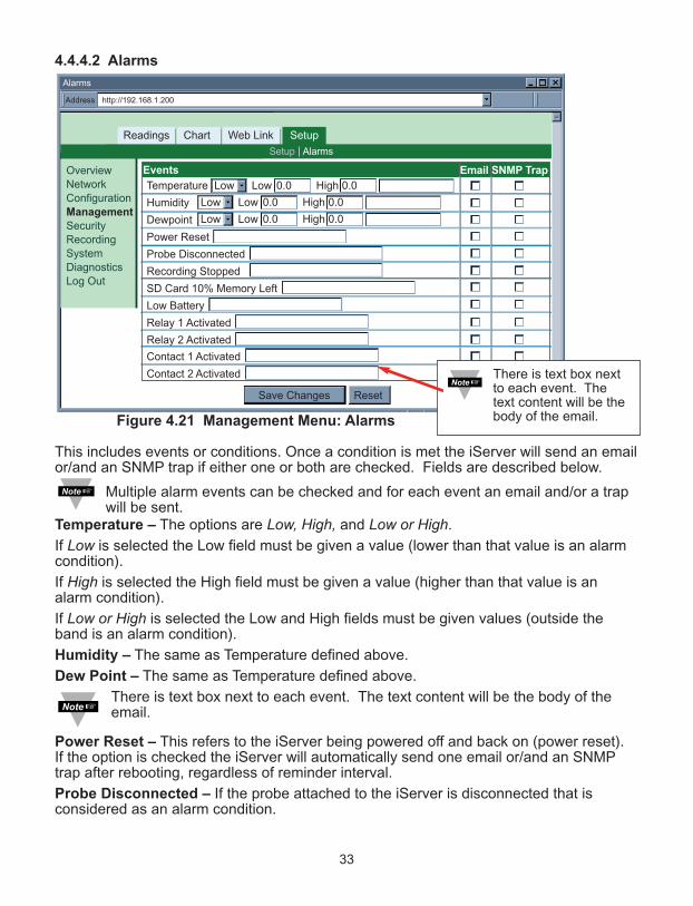
4.4.4.2 Alarms
Figure 4.21 Management Menu: Alarms
This includes events or conditions. Once a condition is met the iServer will send an emailor/and an SNMP trap if either one or both are checked. Fields are described below.
Multiple alarm events can be checked and for each event an email and/or a trapwill be sent.
Temperature – The options are Low, High, and Low or High.
If Low is selected the Low field must be given a value (lower than that value is an alarmcondition).
If High is selected the High field must be given a value (higher than that value is analarm condition).
If Low or High is selected the Low and High fields must be given values (outside theband is an alarm condition).
Humidity – The same as Temperature defined above.
Dew Point – The same as Temperature defined above.
There is text box next to each event. The text content will be the body of theemail.
Power Reset – This refers to the iServer being powered off and back on (power reset).If the option is checked the iServer will automatically send one email or/and an SNMPtrap after rebooting, regardless of reminder interval.
Probe Disconnected – If the probe attached to the iServer is disconnected that isconsidered as an alarm condition.
http://192.168.1.200Address
Alarms
Readings Chart Web Link Setup
OverviewNetworkConfigurationManagement
SecurityRecordingSystemDiagnosticsLog Out
Save Changes Reset
Temperature Low Low 0.0 High 0.0Low 0.0 0.0
Low HighLow 0.0 0.0
Low HighLow 0.0 0.0
Humidity
Dewpoint
Power Reset
Probe Disconnected
Recording Stopped
SD Card 10% Memory Left
Low Battery
Relay 1 Activated
Relay 2 Activated
Events Email SNMP Trap
AlarmsSetup
Contact 1 Activated
Contact 2 Activated
33
There is text box nextto each event. Thetext content will be thebody of the email.
34
4.4.4.2 Alarms (continued)
Recording Stopped – If the iServer is recording, once the recording is stopped (nomatter what the cause was) an email or/and a trap will be sent.
SD Card 10% Memory Left – An alarm will be triggered if 10% or less memory left onthe flash card.
Low Battery – If the 9V battery lowers to about 7V, the iServer will prompt an alarm.
Relay 1 Activated – If relay 1 is activated the iServer will prompt an alarm. See AlarmRelays section under the Configuration page (Section 4.4.3.5).
Relay 2 Activated – If relay 2 is activated the iServer will prompt an alarm. See AlarmRelays section under the Configuration page (Section 4.4.3.5).
Contact 1 Activated – If contact 1 is activated the iServer will prompt an alarm. SeeContact Closures section under the Configuration page (Section 4.4.3.4).
Contact 2 Activated – If contact 2 is activated the iServer will prompt an alarm. SeeContact Closures section under the Configuration page (Section 4.4.3.4).
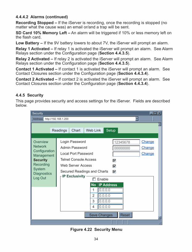
4.4.5 Security
This page provides security and access settings for the iServer. Fields are describedbelow.
Figure 4.22 Security Menu
http://192.168.1.200Address
Security
Readings Chart Web Link Setup
OverviewNetworkConfigurationManagementSecurity
RecordingSystemDiagnosticsLog Out
Save Changes Reset
Login Password
Admin Password
Local Port Password
Telnet Console Access
Web Server Access
Secured Readings and Charts
Change
Change
Change
IP Exclusivity
12345678
00000000
1
2
3
4
0.0.0.0
0.0.0.0
0.0.0.0
0.0.0.0
Enable
No IP Address

4.4.5 Security (continued)
Login Password – To access Readings, Chart, and Web Link menus this password isrequired. The password length can be up to 16 alphanumeric case-sensitive characters.To change the password click on Change.
Empty box means no password is required. The default Login Password is 12345678.
Administrator Password – To access Setup menu this password is required. Thepassword length can be up to 16 alphanumeric case-sensitive characters. To change thepassword click on Change.
Empty box means no password is required. The default Administrator Password is00000000.
This password will also be prompted when Telnet connection to port 2002 ismade. Port 2002 is the Telnet console port that allows users to configure someof the parameters that can be configured through the web server.
Local Port Password – To access the iServer (via TCP or UDP socket connection toport 2000) this password is required. The maximum length can be up to 16alphanumeric case-sensitive characters.
Empty box means no password is required. The default is none.
Telnet Console Access – If it is unchecked, Telnet console connection to port 2002 willbe blocked. The iServer must be rebooted for the change to take place. The default ischecked.
Web Server Access – If it is unchecked, the iServer’s Web server will not be accessed.The iServer must be rebooted for the change to take place. The default is checked.
When the Web Server Access is not enabled, the iServer needs to beconfigured using Telnet console.
If someone needs to access the Web Server again, use the Telnet console toenable it.
Secured Readings and Charts – If it is checked the Login password will be required todisplay Readings and Chart applets. The default is checked.
IP Exclusivity – This table contains the IP addresses that are allowed to communicatewith the iServer over TCP or UDP connection. This means if the table is emptyconnections from all IP nodes are allowed to the iServer. If enabled, all packets from IPaddresses not on this list are ignored and thrown away.
35
36
4.4.6 Recording
This section includes all the parameters and settings for data recording, SD flash cardand recording status, data retrieval, and formatting the SD card. Fields are describedbelow.
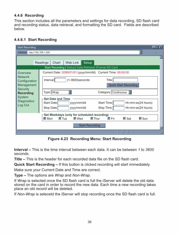
4.4.6.1 Start Recording
Figure 4.23 Recording Menu: Start Recording
Interval – This is the time interval between each data. It can be between 1 to 3600seconds.
Title – This is the header for each recorded data file on the SD flash card.
Quick Start Recording – If this button is clicked recording will start immediately.
Make sure your Current Date and Time are correct.
Type – The options are Wrap and Non-Wrap.
If Wrap is selected once the SD flash card is full the iServer will delete the old datastored on the card in order to record the new data. Each time a new recording takesplace an old record will be deleted.
If Non-Wrap is selecetd the iServer will stop recording once the SD flash card is full.
http://192.168.1.200Address
Start Recording
Readings Chart Web Link Setup
OverviewNetworkConfigurationManagementSecurityRecording
SystemDiagnosticsLog Out
Format SD CardStart Recording Status Data Retrieval
Interval (1-3600)seconds
yyyy/mm/dd
yyyy/mm/dd
Start Time
Stop Time
Start Date
Stop Date
hh:mm:ss(24 hours)
hh:mm:ss(24 hours)
Set Date and Time
Mon Tue Wed Thur Fri Sat SunSet Weekdays (only for scheduled recording)
Current Date: 2099/01/01 (yyyy/mm/dd) Current Time: 00:00:00
ContinuousCategoryWrapType
Quick Start Recording
Title
Start Recording
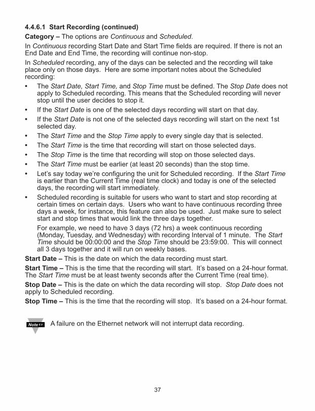
37
4.4.6.1 Start Recording (continued)
Category – The options are Continuous and Scheduled.
In Continuous recording Start Date and Start Time fields are required. If there is not anEnd Date and End Time, the recording will continue non-stop.
In Scheduled recording, any of the days can be selected and the recording will takeplace only on those days. Here are some important notes about the Scheduledrecording:
• The Start Date, Start Time, and Stop Time must be defined. The Stop Date does notapply to Scheduled recording. This means that the Scheduled recording will neverstop until the user decides to stop it.
• If the Start Date is one of the selected days recording will start on that day.
• If the Start Date is not one of the selected days recording will start on the next 1stselected day.
• The Start Time and the Stop Time apply to every single day that is selected.
• The Start Time is the time that recording will start on those selected days.
• The Stop Time is the time that recording will stop on those selected days.
• The Start Time must be earlier (at least 20 seconds) than the stop time.
• Let’s say today we’re configuring the unit for Scheduled recording. If the Start Timeis earlier than the Current Time (real time clock) and today is one of the selecteddays, the recording will start immediately.
• Scheduled recording is suitable for users who want to start and stop recording atcertain times on certain days. Users who want to have continuous recording threedays a week, for instance, this feature can also be used. Just make sure to selectstart and stop times that would link the three days together.
For example, we need to have 3 days (72 hrs) a week continuous recording(Monday, Tuesday, and Wednesday) with recording Interval of 1 minute. The StartTime should be 00:00:00 and the Stop Time should be 23:59:00. This will connectall 3 days together and it will run on weekly bases.
Start Date – This is the date on which the data recording must start.
Start Time – This is the time that the recording will start. It’s based on a 24-hour format.The Start Time must be at least twenty seconds after the Current Time (real time).
Stop Date – This is the date on which the data recording will stop. Stop Date does notapply to Scheduled recording.
Stop Time – This is the time that the recording will stop. It’s based on a 24-hour format.
A failure on the Ethernet network will not interrupt data recording.

38
4.4.6.2 Status
This page describes the Recording and SD flash card status. All the fields on this pageare read-only.
Figure 4.24 Recording Menu: Status
http://192.168.1.200Address
Status
Readings Chart Web Link Setup
Recording
StartDate
StopDate
Category
Interval
OFF
(yyyy/mm/dd)
(yyyy/mm/dd)
StartTime
StopTime
Type
Title
(hh:mm:ss)(24 hours)
(hh:mm:ss)(24 hours)
Recording Status
SD Card Detected
SD Card Write Protected
Total Flash Size
Available Flash Size
YES
NO
1925456(KB)
1925452(KB)
SD Card Status
Check BatteryBattery Status
Current Date: 2099/01/01 Current Time: 00:00:00
Uptime 0 days,00:00:00 hh:mm:ss
Format SD CardStart Recording Status Data Retrieval
OverviewNetworkConfigurationManagementSecurityRecording
SystemDiagnosticsLog Out
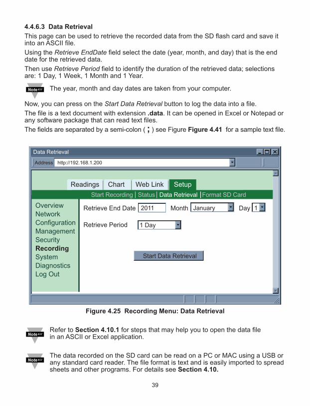
39
4.4.6.3 Data Retrieval
This page can be used to retrieve the recorded data from the SD flash card and save itinto an ASCII file.
Using the Retrieve EndDate field select the date (year, month, and day) that is the enddate for the retrieved data.
Then use Retrieve Period field to identify the duration of the retrieved data; selectionsare: 1 Day, 1 Week, 1 Month and 1 Year.
The year, month and day dates are taken from your computer.
Now, you can press on the Start Data Retrieval button to log the data into a file.
The file is a text document with extension .data. It can be opened in Excel or Notepad orany software package that can read text files.
The fields are separated by a semi-colon ( ; ) see Figure Figure 4.41 for a sample text file.
Figure 4.25 Recording Menu: Data Retrieval
Refer to Section 4.10.1 for steps that may help you to open the data file in an ASCII or Excel application.
The data recorded on the SD card can be read on a PC or MAC using a USB orany standard card reader. The file format is text and is easily imported to spreadsheets and other programs. For details see Section 4.10.
http://192.168.1.200Address
Data Retrieval
Readings Chart Web Link Setup
Start Data Retrieval
Format SD CardStart Recording Status Data Retrieval
1 DayRetrieve Period
Retrieve End Date Month Day OverviewNetworkConfigurationManagementSecurityRecording
SystemDiagnosticsLog Out
2011 January 1
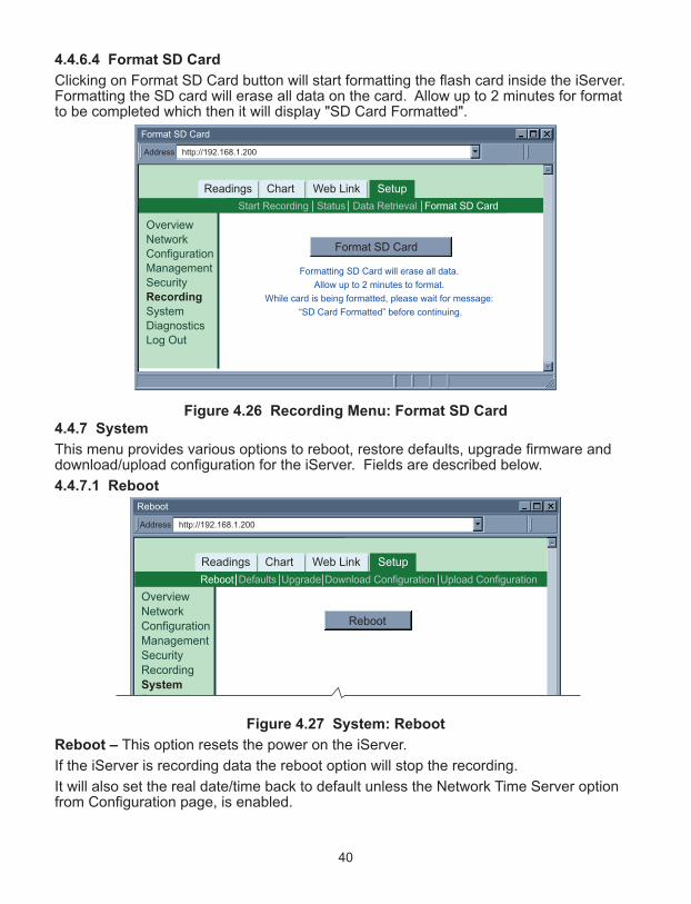
40
4.4.6.4 Format SD Card
Clicking on Format SD Card button will start formatting the flash card inside the iServer.Formatting the SD card will erase all data on the card. Allow up to 2 minutes for formatto be completed which then it will display "SD Card Formatted".
Figure 4.26 Recording Menu: Format SD Card
4.4.7 System
This menu provides various options to reboot, restore defaults, upgrade firmware anddownload/upload configuration for the iServer. Fields are described below.
4.4.7.1 Reboot
Figure 4.27 System: Reboot
Reboot – This option resets the power on the iServer.
If the iServer is recording data the reboot option will stop the recording.
It will also set the real date/time back to default unless the Network Time Server optionfrom Configuration page, is enabled.
http://192.168.1.200Address
Format SD Card
Readings Chart Web Link Setup
Format SD Card
Formatting SD Card will erase all data.
Allow up to 2 minutes to format.
While card is being formatted, please wait for message:
“SD Card Formatted” before continuing.
Format SD CardStart Recording Status Data Retrieval
OverviewNetworkConfigurationManagementSecurityRecording
SystemDiagnosticsLog Out
http://192.168.1.200Address
Reboot
Readings Chart Web Link Setup
Reboot
DefaultsReboot Download ConfigurationUpgrade Upload Configuration
OverviewNetworkConfigurationManagementSecurityRecordingSystem
Di ti

41
4.4.7.2 DefaultsClicking on this button will put the iServer back to its default settings.
Figure 4.28 System: Defaults
4.4.7.3 Upgrade
Figure 4.29 System: Upgrade
Upgrade – This option loads a new firmware into the iServer over the network. Thefirmware is a binary file with .bin extension. This file must be kept on the same PC fromwhich the iServer is accessed. Once the firmware upload is completed the iServer will power reset itself. This typicallytakes about 30 seconds.
When doing firmware upgrade on the iServer, there should be NO other on-going or new Web server (HTTP) connections made to the device; otherwise,the iServer will not upgrade the firmware. You can do either of the following toprevent this from happening:
1. Connect the iServer directly to the PC using a straight or crossed Ethernet cable. Thiswill also help to have a faster firmware upload.
2. From the “Network” menu, change the Web Server Port, for example, to 500 (defaultis 80), save the change, and reset the power on your iServer. The next time you willaccess the iServer’s Web server, you must type http://192.168.1.200:500 where192.168.1.200 is the IP address of the iServer and 500 is the new Web server port(HTTP port).
Either one of the above options will make you the only user on that iServer.
http://192.168.1.200Address
Defaults
Readings Chart Web Link Setup
Restore Factory Defaults
DefaultsReboot Download ConfigurationUpgrade Upload Configuration
OverviewNetworkConfigurationManagementSecurityRecordingSystem
http://192.168.1.200Address
Upgrade Firmware
Readings Chart Web Link Setup
Upgrade
Filename: iSD-TH*.bin
DefaultsReboot Download ConfigurationUpgrade Upload Configuration
Browse...
OverviewNetworkConfigurationManagementSecurityRecordingSystem
Diagnostics
Please make sure no other clients are connected to the device.Consult manual for complete instructions.
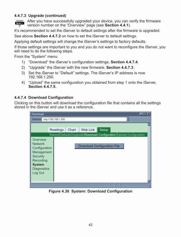
42
4.4.7.3 Upgrade (continued)
After you have successfully upgraded your device, you can verify the firmwareversion number on the “Overview” page (see Section 4.4.1).
It’s recommended to set the iServer to default settings after the firmware is upgraded.
See above Section 4.4.7.2 on how to set the iServer to default settings.
Applying default settings will change the iServer’s settings to factory defaults.
If those settings are important to you and you do not want to reconfigure the iServer, youwill need to do the following steps.
From the “System” menu:
1) “Download” the iServer’s configuration settings, Section 4.4.7.4.
2) “Upgrade” the iServer with the new firmware, Section 4.4.7.3.
3) Set the iServer to “Default” settings. The iServer’s IP address is now192.168.1.200.
4) “Upload” the same configuration you obtained from step 1 onto the iServer,Section 4.4.7.5.
4.4.7.4 Download Configuration
Clicking on this button will download the configuration file that contains all the settingsstored in the iServer and use it as a reference.
Figure 4.30 System: Download Configuration
http://192.168.1.200Address
Download
Readings Chart Web Link Setup
Download Configuration File
DefaultsReboot Download ConfigurationUpgrade Upload Configuration
OverviewNetworkConfigurationManagementSecurityRecordingSystem
DiagnosticsLog Out

43
4.4.7.5 Upload Configuration
Figure 4.31 System: Upload Configuration
Upload Configuration – Using this option to upload the configuration file into theiServer. It is recommended to download and store a working copy of this configurationfile in case the device is configured improperly.
You can set the iServer to its default settings and upload the configuration fileback into the iServer.
4.4.8 DiagnosticsThis page provides the number of Ethernet packets received or transmitted. Pressing theReset Counter button will set the counts to zero.
Figure 4.32 Diagnostics4.4.9 Log OutOnce you click on Log Out, you will be logged out, and taken back to the Welcome page.
http://192.168.1.200Address
Upload Configuration
Readings Chart Web Link Setup
Upload Configuration File *.cfg
DefaultsReboot Download ConfigurationUpgrade Upload Configuration
Browse...
OverviewNetworkConfigurationManagementSecurityRecordingSystem
DiagnosticsLog Out
Please make sure no other clients are connected to the device.Consult manual for complete instructions.
http://192.168.1.200Address
Diagnostics
Readings Chart Web Link Setup
Ethernet Received Transmitted
Packets 4437 6073 Reset Counter
OverviewNetworkConfigurationManagementSecurityRecordingSystemDiagnostics
Log Out

44
4.5 Readings
This page displays temperature, humidity, dew point, and the status of the alarm relaysand recording.
It can be displayed either as an HTML page or a Java applet.
4.5.1 HTML
Figure 4.33 Readings: HTML
Refresh – Adding a time value in seconds will automatically update the HTML page withfresh readings.
http://192.168.1.200Address
Readings
Temperature
Humidity
Dewpoint
23.0 C
47.3%
11.0 C
ACTIVE LOW
Contact2 ACTIVE
Recording ON
Output
Contact1 NORMAL
Readings Chart Web Link Setup
JavaHTML
Auto UpdateSeconds2Refresh

45
4.5.2 Java
If Java option is chosen installation of Java Runtime is required (refer to Appendix G).
Figure 4.34 Readings: Java
Data Logging – This option will require the Java Policy file to be setup.
Press on Help[?] for details.
An alternate way to set up the Java Policy can be found in Appendix G.
Once the Java Policy file is completed, click on Data Logging button to log the datadisplayed on this page into a file. The file is in comma separated values (.csv) format,which can be opened in Excel or as ASCII. The fields are separated by a comma ( , ).
When the button is ACTIVE it means that the data is currently being logged into a file.The value in seconds in the Refresh box determines how often the data is being logged.The default is 2 seconds.
If you want to access the “Chart” and/or the “Readings” applet from outside yourlocal network on which the iServer is connected, you must allow ports 1001(Readings) and 2003 (Chart) on your Router.
If a blank screen appears without any “java application running” or image of a“Java logo”, please verify you have the latest Java Runtime Environment installedand configured according to the instructions (refer to Appendix G). If you do nothave Java Runtime Environment installed, you may download it from our website(in the software section) or contact the Customer Service Department nearest you.
“Java and the Java Coffee Cup Logo are trademarks or registered trademarks of Sun Microsystems, Inc. in the U.S. and other countries."
Help[?]
http://192.168.1.200Address
Readings
Temperature
Humidity
Dewpoint
23.0 C
47.3%
11.0 C
ACTIVE LOW
Contact2 ACTIVE
Recording ON
Output
Contact1 NORMAL
Readings Chart Web Link Setup
JavaHTML
Auto UpdateSeconds2Refresh
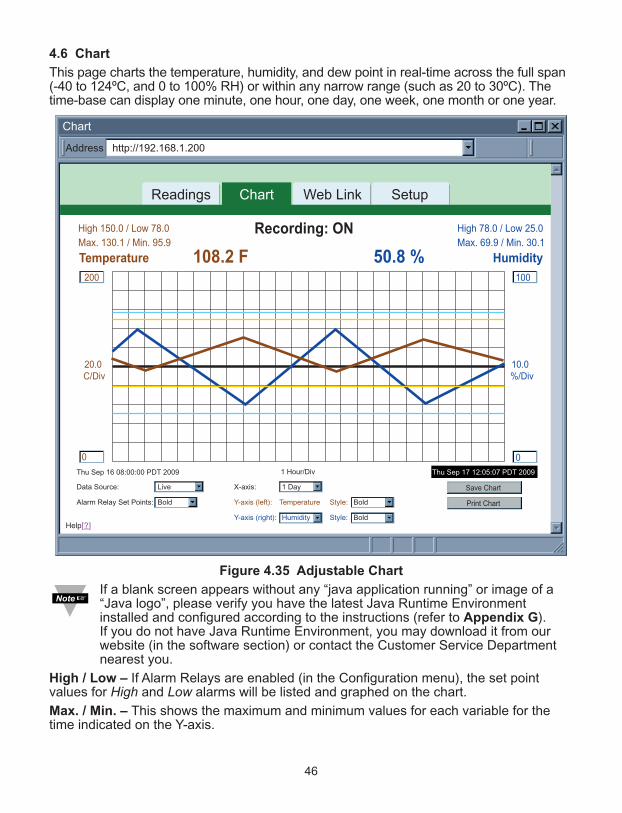
46
4.6 Chart
This page charts the temperature, humidity, and dew point in real-time across the full span(-40 to 124ºC, and 0 to 100% RH) or within any narrow range (such as 20 to 30ºC). Thetime-base can display one minute, one hour, one day, one week, one month or one year.
Figure 4.35 Adjustable Chart
If a blank screen appears without any “java application running” or image of a“Java logo”, please verify you have the latest Java Runtime Environmentinstalled and configured according to the instructions (refer to Appendix G). If you do not have Java Runtime Environment, you may download it from ourwebsite (in the software section) or contact the Customer Service Departmentnearest you.
High / Low – If Alarm Relays are enabled (in the Configuration menu), the set pointvalues for High and Low alarms will be listed and graphed on the chart.
Max. / Min. – This shows the maximum and minimum values for each variable for thetime indicated on the Y-axis.
http://192.168.1.200Address
Chart
1 Hour/Div
20.0C/Div
10.0%/Div
Temperature Humidity
Max. 130.1 / Min. 95.9 Max. 69.9 / Min. 30.1High 150.0 / Low 78.0 High 78.0 / Low 25.0
100
0
200
0
Save Chart
Print Chart
108.2 F 50.8 %
Thu Sep 17 12:05:07 PDT 2009Thu Sep 16 08:00:00 PDT 2009
Data Source:
Alarm Relay Set Points:
Y-axis (right):
Live
Bold
Humidity Style: Bold
Y-axis (left): Temperature Style: Bold
X-axis: 1 Day
Readings Chart Web Link Setup
Recording: ON
Help[?]
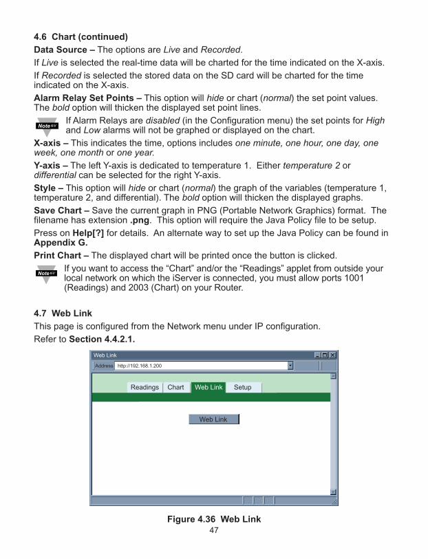
47
4.6 Chart (continued)
Data Source – The options are Live and Recorded.
If Live is selected the real-time data will be charted for the time indicated on the X-axis.
If Recorded is selected the stored data on the SD card will be charted for the timeindicated on the X-axis.
Alarm Relay Set Points – This option will hide or chart (normal) the set point values.The bold option will thicken the displayed set point lines.
If Alarm Relays are disabled (in the Configuration menu) the set points for Highand Low alarms will not be graphed or displayed on the chart.
X-axis – This indicates the time, options includes one minute, one hour, one day, oneweek, one month or one year.Y-axis – The left Y-axis is dedicated to temperature 1. Either temperature 2 ordifferential can be selected for the right Y-axis.
Style – This option will hide or chart (normal) the graph of the variables (temperature 1,temperature 2, and differential). The bold option will thicken the displayed graphs.
Save Chart – Save the current graph in PNG (Portable Network Graphics) format. Thefilename has extension .png. This option will require the Java Policy file to be setup.
Press on Help[?] for details. An alternate way to set up the Java Policy can be found inAppendix G.
Print Chart – The displayed chart will be printed once the button is clicked.
If you want to access the “Chart” and/or the “Readings” applet from outside yourlocal network on which the iServer is connected, you must allow ports 1001(Readings) and 2003 (Chart) on your Router.
4.7 Web Link
This page is configured from the Network menu under IP configuration.
Refer to Section 4.4.2.1.
Figure 4.36 Web Link
http://192.168.1.200Address
Web Link
Readings Chart Web Link Setup
Web Link
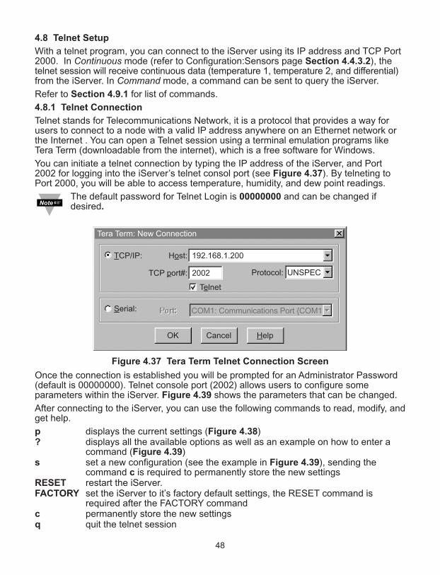
4.8 Telnet Setup
With a telnet program, you can connect to the iServer using its IP address and TCP Port2000. In Continuous mode (refer to Configuration:Sensors page Section 4.4.3.2), thetelnet session will receive continuous data (temperature 1, temperature 2, and differential)from the iServer. In Command mode, a command can be sent to query the iServer.
Refer to Section 4.9.1 for list of commands.
4.8.1 Telnet Connection
Telnet stands for Telecommunications Network, it is a protocol that provides a way forusers to connect to a node with a valid IP address anywhere on an Ethernet network orthe Internet . You can open a Telnet session using a terminal emulation programs likeTera Term (downloadable from the internet), which is a free software for Windows.
You can initiate a telnet connection by typing the IP address of the iServer, and Port2002 for logging into the iServer’s telnet consol port (see Figure 4.37). By telneting toPort 2000, you will be able to access temperature, humidity, and dew point readings.
The default password for Telnet Login is 00000000 and can be changed ifdesired.
Figure 4.37 Tera Term Telnet Connection Screen
Once the connection is established you will be prompted for an Administrator Password(default is 00000000). Telnet console port (2002) allows users to configure someparameters within the iServer. Figure 4.39 shows the parameters that can be changed.
After connecting to the iServer, you can use the following commands to read, modify, andget help.
p displays the current settings (Figure 4.38)? displays all the available options as well as an example on how to enter a
command (Figure 4.39)s set a new configuration (see the example in Figure 4.39), sending the
command c is required to permanently store the new settingsRESET restart the iServer.FACTORY set the iServer to it’s factory default settings, the RESET command is
required after the FACTORY commandc permanently store the new settingsq quit the telnet session
192.168.1.200
UNSPEC
Host:TCP/IP:
Serial:
2002TCP port#: Protocol:
COM1: Communications Port {COM1
Telnet
Tera Term: New Connection
Cancel HelpOK
48

49
4.8.1 Telnet Connection (continued)
Figure 4.38 Figure 4.39
Telnet to Port 2002 – p command Telnet to Port 2002 – ? command
4.9 HTTPget Program
The HTTPget software is used to send a single HTTP or TCP request to an iServerproduct. In contrast, the telnet or Hyperterminal programs allow a continuousconnection with multiple requests to be sent to the iServer product.
Generally HTTPget is used for simply programming an IP address to the iServer or forquickly obtaining a reading of from a device.
The iServer product must be configured from the configuration web page so that the"Server Type" value is set to "Command", refer to Section 4.4.3.2.
1.0Administrator Password?00000000iSD-TH>iSD-TH>pModel: iSD-THFirmware Ver: 1.0.1
DP: Disabled (0)MC: 00:03:34:00:B9:B6IP: 192.168.1.200SM: 255.255.255.0GW: 0.0.0.0LP: 12345678SP: 00000000CP:
TC: Enabled (1)WS: Enabled (1)SR: Enabled (1)iSD-TH>
iSD-TH>
1.0.1Administrator Password?00000000iSD-TH>iSD-TH>Configuration Commands:

50
4.9.1 HTTPget using Port 2000
You can setup and read the information from the iServer by using the HTTPget program.The following program can be used to read data from the iServer by using TCP port2000. The command string is sent to this TCP port, then the response can be read backfrom the same socket.
The HTTPget.exe file is used to setup and read information from the iServer. This file canbe downloaded from the website listed on the cover of this manual (software section).
Notes on using HTTPget :
The HTTPget.exe program should be installed to the windows directory (usually c:\winntor c:\windows)
1. Open up a command window (or have a DOS window)
a) Click on start menu
b) Click on "Run"
c) In the dialog box that appears, type "cmd" or "command" and click on "OK" button.
d) A command window should now appear.
2. If you now type "httpget" and press the "enter" key, the program options should bedisplayed.
3. Next run HTTPget with the options displayed below
httpget -r -S “*SRTC\r” 192.168.1.200:2000
where:
-r –S are parameters needed for the command string*SRTC is the command as the following:
*SRTC Read the temperature in C, celcius*SRTF Read the temperature in F, fahrenheit *SRH Read humidity*SRD Read the dew point in C*SRDF Read the dew point in F*SRA1 Read alarm set points for relay 1*SRA2 Read alarm set points for relay 2*SRB Read the temperature in C and humidity*SRBF Read the temperature in F and humidity*SRYS Indicate AC or DC power and battery status*SRYRST Reset Power on*SR_XD1 Disable alarm condition check for relay 1*SR_XD2 Disable alarm condition check for relay 2

4.9.1 HTTPget using Port 2000 (continued)
*SR_XC1 Reset relay 1 latch condition*SR_XC2 Reset relay 2 latch condition*SR_XE1 Re-enable alarm condition check for relay 1 (must be
executed after *SR_XD1)*SR_XE2 Re-enable alarm condition check for relay 2 (must be
executed after *SR_XD2)*SR_XP1 Close relay 1 for < 200 mSec*SR_XP2 Close relay 2 for < 200 mSec*SR_XH1 Close relay 1*SR_XH2 Close relay 2*SR_XL1 Open relay 1*SR_XL2 Open relay 2*SR_XR1 Read current state of relay 1*SR_XR2 Read current state of relay 2*SRT2 Status of Contact 1 (Disable, Normal, Active)*SRH2 Status of Contact 2 (Disable, Normal, Active)*SRD2 Status of the Output associated with the Contacts
(Active High, Active Low)\r is the carriage return termination character
192.168.1.200 is an IP address 2000 is a socket port number
Response:
076.6 (in Deg.F format)
4.10 Flash Card Reader
The data recorded on the SD card can be read on a PC or MAC with a USB or anystandard card reader.
The format is a simple “.txt” text file that is easily imported in MS Excel or MS WordPador any software package that can read text files (see Figure 4.41).
The entire recording session is saved into a file kept in the root directory.
The name of this file is S followed by the date the recording was started , so for example:S20100401.txt is April 1st, 2010.
The same recording data is also saved into daily files located in a series of month andyear directories in which the recording took place (see Figure 4.40).
51

4.10 Flash Card Reader (continued)
Figure 4.40 Recorded Data File Directory
Figure 4.41
Example of data recorded on the
SD card, standard text (.txt) file format
4.10.1 Opening .txt Data Files
1. Right-click on the data file and select Open with Wordpad. This will display the ASCIIdata in WordPad.
2. From the Edit menu select the Replace option to replace all the ; (semicolons) with , (commas).
3. From the File menu select Save As and save the file with an extension .csv (CommaSeparated Value).
4. This .csv file can now be opened in Excel with the correct format.Alternatively, you can do the following--
1 Open Excel. Go to File, Open, select Files of Type: Choose Text files (*.prn, *.txt,*.csv), and then select the data file you wish to open.
2. A Text Import Wizard should pop-up. Select Delimited type of file, then Next. Click on semicolon as the Delimiter type, then Next. The screen should show how the file is being divided into columns, click on Finish.
3 From the File menu select Save As and save the file with an extension .csv.
The next time you open this file it will open in Excel automatically.You may remove the letters C or F and D from the recorded values (using theReplace option of Excel or Wordpad). This will enable you to create charts of the data.
E:\
2010EventsS20100401.txt 15,598KB
File FolderFile FolderText Document
4/01/2010 8:08AM4/01/2010 8:08AM5/02/2010 1:08PM
Name
File Edit View Favorites Tools Help
Type Date ModifiedSize
E:\2010
0405
File FolderFile Folder
4/01/2010 8:08AM5/02/2010 1:08PM
Name
File Edit View Favorites Tools Help
Type Date ModifiedSize
E:\2010\04
20100401.txt20100402.txt20100403.txt20100404.txt20100405.txt20100406.txt20100407.txt
598 KB598 KB598 KB598 KB598 KB598 KB598 KB
Text DocumentText DocumentText DocumentText DocumentText DocumentText DocumentText Document
4/02/2010 12:00AM4/03/2010 12:00AM4/04/2010 12:00AM4/05/2010 12:00AM4/06/2010 12:00AM4/07/2010 12:00AM4/08/2010 12:00AM
Name
File Edit View Favorites Tools Help
Type Date ModifiedSize
#2010/04/02;09:00:00;23.3C;35.6%;D6.7C;#2010/04/02;09:00:10;23.3C;35.6%;D6.7C;#2010/04/02;09:00:20;23.3C;35.6%;D6.7C;#2010/04/02;09:00:30;23.3C;35.7%;D6.7C;#2010/04/02;09:00:40;23.3C;35.7%;D6.7C;
52

4.11 iLog Software
This is an Excel application software that can log temperature, humidity and dewpointfrom the iServer over the local network (Ethernet) or the internet.
a) Download the iLog software from the website listed in this manual.
b) Install iLog software on a networked PC. This software is compatible with Windows95, 98, NT, 2000, XP, Windows Vista and Windows 7 (32 and 64-bit).
c) If you have Excel 2007 or higher, when installing iLog choose “Custom” installation option and on the next window check the box for “Excel 2007 Apps” and continue the installation to the end.
d) For complete information of how to use the iLog software, click on the HELP button.
e) There is a list of Error Messages in Appendix E.
Figure 4.42 iLog Software Logging Data
The Options button will let you select the product model. Choose iSD-TH from the Model Selection pull-down menu (from General tab).
53

iLog Software (continued)
Table 4.1 iLog Excel Applications
The iLog application actually consists of several Excel files, though most supporteddevices can be accessed by the main iLog program. The main program is listed as"iLog", plus a version number, under the Start Menu program links (those links availableby clicking the Start button on the Windows taskbar).In the following table, the iLog File column shows how many sensors are logged by themain iLog file. If more than 3 sensors are available, then the Alternate column showshow many sensors the device can support. Devices with more than 3 sensors will havetheir own Excel file. For these files, click on the model device found in the Start Menu.
Networked Product iLog File AlternateiTHX-W, iTHX-2 3 columniTHX-M, iTHX-SD 3 columniTHX-W Dual Probe 1st probe / 3 column 6 columniSE-TC, iSD-TC 3 column 5 columniSE-TH, iSD-TH 3 column 5 columniBTHX-W, iBTHX-D 3 column 4 columniBTX-W/-D, iBTX-M, iBTX-SD 2 columniPTX-W 2 columniTCX 3 columniTH Controller 3 columniVI 3 column 4 columniSeries 1 columniDRX/iDRN 1 columnINF-B 1 column
Wireless Devices
The "Auto" column shows number of columns per remote device that are possiblydisplayed. The Full column shows number of columns allocated per device for the "Full"spreadsheet, which will be able to display all data for all active devices.
Networked Product Auto FullzSeries Receiver and Remotes 1 to 4 column / device 4 column / 32 devicewiSeries with zED Remotes 1 to 2 column / device 2 column / 32 deviceUWTC REC-3 and Remotes 1 or 2 column / device 2 column / 32 devicewiSeries with UWTC Remotes 1 to 2 column / device 2 column / 32 device
The active wireless devices, when shown in the Excel application, will be shown withthe device number and the units returned.
54

PART 5SPECIFICATIONS
SENSOR SPECIFICATIONSRelative Humidity (RH)
Accuracy/Range: ±2% for 10 to 90%; ±3% for 5 to 10% and 90 to 95%±4% for 0 to 5% and 95 to 100%Refer to chart in Appendix H
Hysteresis: ±1% RHNon-linearity: ±3%Response Time: 8 seconds, tau 63% (time for reaching 63% of a step
function, valid at 25C and 1m/s airflow)Repeatability: ±0.1%Resolution: 0.1%, 12bit
NOTE: Reconditioning of the probe may be necessary ifthe probe is stored for a period of time in a harshenvironment (temperatures below 0°C or above 70°C orexposure to chemical vapors, condensation, etc).To recondition the probe refer to Appendix H.4
Temperature (T)
Accuracy/Range*:
Wand Probe: ±0.5°C for 5° to 45°C (±1°F for 41° to 113°F);Up to ±1°C for 0° to 5°C and 45° to 60°C Up to ±2°F for 32° to 41°F and 113° to 140°F)Refer to chart in Appendix H
Industrial Probe: ±0.5°C for 5° to 45°C ( ±1°F for 41 to 113°F); Up to ±1.5°C for -40° to 5°C and 45° to 124°C Up to ±2.7°F for -40° to 41°F and 113° to 255°F)Refer to chart in Appendix H
*Note: extended temperature range is for Industrial Probeonly, the iServer’s operating temperature is 0 to 60°C
Response Time: 5 to 30 seconds, tau 63% (response time depends on heatcapacity of and thermal resistance to sensor substrate)
Repeatability: ±0.1°CResolution: 0.1°C, 14 bit
PROBE SPECIFICATIONSStandard Probe: 83.8 mm long x 13 mm diameter (3.3" x 0.5")
Industrial Probe: 137mm long x 16mm diameter (5" x 0.63")Cable with mini DIN connector: 3m long (10’)Cable operating temperature: -40 to 125°C (-40 to 257°F)
55

iSERVER SPECIFICATIONSInterfaces
Ethernet (RJ45): Fixed or auto-negotiating 10/100Base-T; Auto MDI/MDIXSupported Protocols: TCP, UDP, SNMP, SMTP, SNTP, ARP, ICMP, DNS, DHCP,
HTTP, and TelnetLED Indicators: 100 BASE-T, Network Link and Activity, DHCP, RecordingLCD Display: 32 digits, 4.8 x 9.7mm (0.19 x 0.38”)Memory Data Flash Card: 2 GB SD Flash Card for 8 months of data storage at
1 second recording intervals, or 7 years at 10 seconds Relay Outputs: Two relays 1.5A @ 30VdcAlarm I/Os Two contact inputs, one open collector output
150mA @ 30VdcManagement: Device configuration and monitoring through embedded
WEB serverEmbedded WEB Server: Serves WEB pages containing real-time data and live
updated charts within definable time intervals.POWER
Power Input: 9 to 12 VdcConsumption: 4W Safety Qualified
ac Power Adapter (included) Nominal Output: 9 Vdc @ 0.5 AInput: 100 to 240 Vac, 50/60Hz
Back-up Battery: 9 Vdc, alkaline. 30 hours at 10 second recording intervals,or 60 hours at 1 minute intervals
ENVIRONMENTAL
Operating Temperatures
iServer Unit: 0 to 60°C (32 to 140°F)Battery: -18 to 55°C (-0.4 to 131°F)ac Power Adapter: 0 to 40°C (32 to 104°F)Industrial Cable: -40 to 125°C (-40 to 257°F)Storage Temperature: -40 to 85°C (-40 to 185°F)Material: SS 304 case with wall mount bracketiServer Housing Dimensions: 119.1H x 155.7W x 33.3D mm (4.69 x 6.13 x 1.31”)
includes probeWeight: 490 g (1.08 lbs.), including batteryGENERAL
Agency Approvals: FCC-B, CE Software: Compatible with Windows operating systems
Firmware upgrade from EthernetOPC Server
iConnect: Configuration software for the Ethernet interfaceiLog: Macro for automatic data logging in MS Excel
56

APPENDIX A GLOSSARY
User of this manual should be familiar with following definitions:
ARP (Address Resolution Protocol) is a protocol for mapping an Internet Protocol address(IP address) to a physical machine address that is recognized in the local network. For example,the IP address in use today is an address that is 32-bits long. In an Ethernet local area network,however, addresses for attached devices are 48-bits long. (The physical machine address isalso known as a Media Access Control or MAC address.) A table, usually called the ARP cache,is used to maintain a correlation between each MAC address and its corresponding IP address.ARP provides the protocol rules for making this correlation and providing address conversion inboth directions.
Ethernet is a network protocol defined by the IEEE 802.3 standard. Ethernet-based networks use MAC Address rather then IP Address to exchange data between computers. Byusing ARP and adding TCP/IP support, Ethernet devices may be connected as part of theInternet. An Ethernet LAN typically uses coaxial cable or special grades of twisted pair wires.The most commonly installed Ethernet systems are called 10BASE-T and provide transmissionspeeds up to 10 Mbps. Devices are connected to the cable and compete for access using aCarrier Sense Multiple Access with Collision Detection (CSMA/CD) protocol.
IP (Internet Protocol) is the method or protocol by which data is sent from one computer toanother on the Internet.
IP address (Internet Protocol address) is a 32-bit number that identifies each sender orreceiver of information that is sent in packets across the Internet.
IP Netmask is a 32-bit pattern of bits used to determine which part of the IP address is thenetwork portion and which part is the host portion.
MAC (Media Access Control) Address is your computer's unique hardware number. Whenyou're connected to the Internet from your computer, a correspondence table relates your IPaddress to your computer's physical (MAC) address on the LAN.
Ping is a utility that tests the network connectivity. It is used to determine if the host is capableof exchanging information with another host.
Port number/Socket number is a way to identify a specific process to which an Internet orother network message is to be forwarded when it arrives at a server. It is a predefined addressthat serves as a route from the application to the Transport layer or from the Transport layer tothe application of the TCP/IP system.
Sockets are a method for communication between a client program and a server program in anetwork and defined as "the endpoint in a connection." Information transferred across theInternet primarily occurs between sockets.
SMTP Simple Mail Transfer Protocol is an Internet standard for electronic mail (email) transferacross the Internet. SMTP clients usually use SMTP to send email messages by specifying theSMTP server. The email server uses SMTP to both send and receive email messages.
SNMP Simple Network Management Protocol is a network monitoring protocol to monitordevices connected to an Ethernet Network.
TCP/IP (Transmission Control Protocol/Internet Protocol) is the basic communicationlanguage or protocol of the Internet. When you are set up with direct access to the Internet, yourcomputer is provided with a copy of the TCP/IP program just as every other computer that youmay send messages to or get information from also has a copy of TCP/IP. TCP/IP often is usedas a general term to indicate generic access to the Internet.
UDP/IP (User Datagram Protocol/Internet Protocol) is the TCP/IP standard protocol thatallows an application program on one machine to send a datagram to an application program onanother. The UDP can be either in Broadcast or Directed form. The Broadcast UDP transmitsdata to every node on the same network. The Directed UDP transmits data to one node only.
57
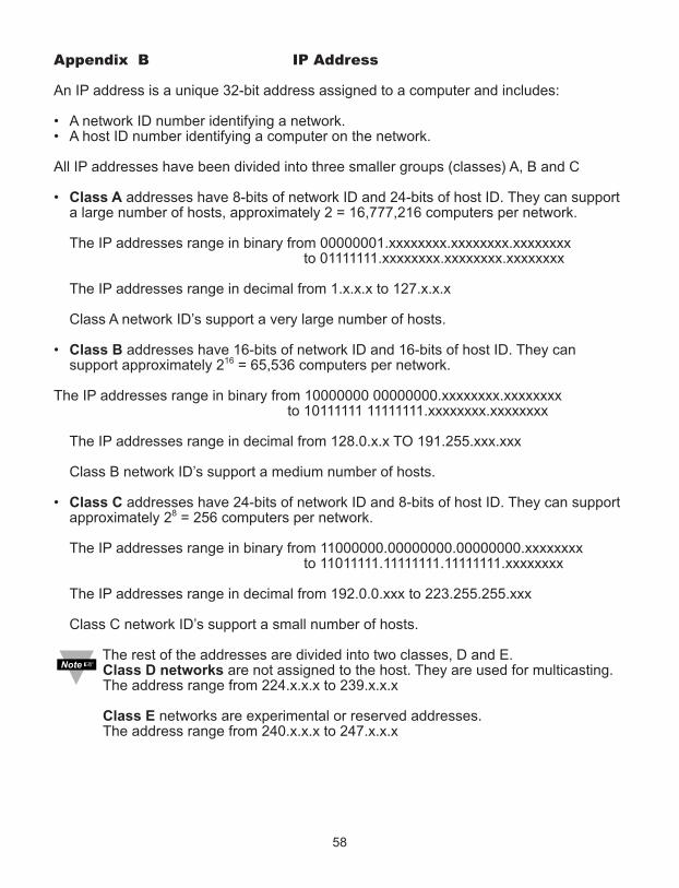
Appendix B IP Address
An IP address is a unique 32-bit address assigned to a computer and includes:
• A network ID number identifying a network.• A host ID number identifying a computer on the network.
All IP addresses have been divided into three smaller groups (classes) A, B and C
• Class A addresses have 8-bits of network ID and 24-bits of host ID. They can support a large number of hosts, approximately 2 = 16,777,216 computers per network.
The IP addresses range in binary from 00000001.xxxxxxxx.xxxxxxxx.xxxxxxxxto 01111111.xxxxxxxx.xxxxxxxx.xxxxxxxx
The IP addresses range in decimal from 1.x.x.x to 127.x.x.x
Class A network ID’s support a very large number of hosts.
• Class B addresses have 16-bits of network ID and 16-bits of host ID. They can support approximately 216 = 65,536 computers per network.
The IP addresses range in binary from 10000000 00000000.xxxxxxxx.xxxxxxxxto 10111111 11111111.xxxxxxxx.xxxxxxxx
The IP addresses range in decimal from 128.0.x.x TO 191.255.xxx.xxx
Class B network ID’s support a medium number of hosts.
• Class C addresses have 24-bits of network ID and 8-bits of host ID. They can support approximately 28 = 256 computers per network.
The IP addresses range in binary from 11000000.00000000.00000000.xxxxxxxx to 11011111.11111111.11111111.xxxxxxxx
The IP addresses range in decimal from 192.0.0.xxx to 223.255.255.xxx
Class C network ID’s support a small number of hosts.
The rest of the addresses are divided into two classes, D and E.Class D networks are not assigned to the host. They are used for multicasting. The address range from 224.x.x.x to 239.x.x.x
Class E networks are experimental or reserved addresses.The address range from 240.x.x.x to 247.x.x.x
58

Appendix C ARP Commands
ARP is the Internet layer protocol responsible for matching or obtaining the MAC(hardware) address that corresponds to a particular IP address. The ARP commandallows the user to view the current contents of the ARP cache of the local computer(residing on the same network). Microsoft includes the ARP.EXE utility for viewing andmodifying the ARP cache with its Windows products. The following ARP commands canbe used to view cache entries:• arp –a fi Use this command to view all ARP cache entries.• arp –a plus IP address fi Use this command to view ARP cache entries associated
with one particular interface on a network with multiple adapters.• arp –g fi Same as arp –a.• arp –N fi Use this command to display ARP entries for specific network interface.• arp – s plus IP address plus Physical address fi Use this command to manually
add a permanent static entry to the ARP cache.• arp –d fi Use this command to manually delete a static entry.
Ping the destination computer using IP address first before using the arp -acommand.
The following window shows examples of arp commands and responses.• Your computer has an IP address of 192.168.1.118
• The destination computer has an IP address of 192.168.1.96
Figure C.1 ARP Commands and Responses
59
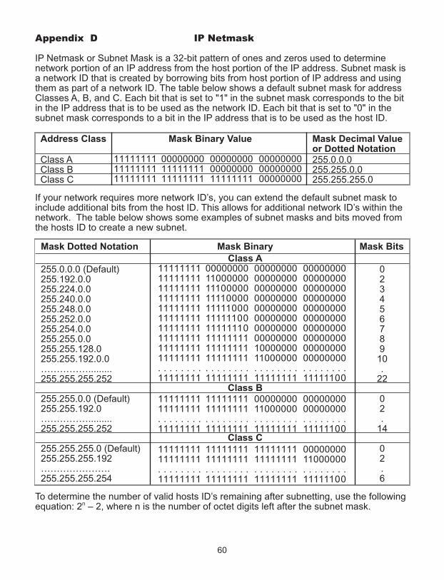
Appendix D IP Netmask
IP Netmask or Subnet Mask is a 32-bit pattern of ones and zeros used to determinenetwork portion of an IP address from the host portion of the IP address. Subnet mask isa network ID that is created by borrowing bits from host portion of IP address and usingthem as part of a network ID. The table below shows a default subnet mask for addressClasses A, B, and C. Each bit that is set to "1" in the subnet mask corresponds to the bitin the IP address that is to be used as the network ID. Each bit that is set to "0" in thesubnet mask corresponds to a bit in the IP address that is to be used as the host ID.
Address Class Mask Binary Value Mask Decimal Valueor Dotted Notation
Class A 255.0.0.0Class B 255.255.0.0Class C 255.255.255.0
If your network requires more network ID’s, you can extend the default subnet mask toinclude additional bits from the host ID. This allows for additional network ID’s within thenetwork. The table below shows some examples of subnet masks and bits moved fromthe hosts ID to create a new subnet.
Mask Dotted Notation Mask Binary Mask Bits
Class A255.0.0.0 (Default) 0255.192.0.0 2255.224.0.0 3255.240.0.0 4255.248.0.0 5255.252.0.0 6255.254.0.0 7255.255.0.0 8255.255.128.0 9255.255.192.0.0 10……………......... .255.255.255.252 22
Class B255.255.0.0 (Default) 0255.255.192.0 2……………......... .255.255.255.252 14
Class C255.255.255.0 (Default) 0255.255.255.192 2…………………. .255.255.255.254 6
To determine the number of valid hosts ID’s remaining after subnetting, use the followingequation: 2n – 2, where n is the number of octet digits left after the subnet mask.
60
111111111111111111111111
000000001111111111111111
000000000000000011111111
000000000000000000000000
11111111111111111111111111111111111111111111111111111111111111111111111111111111. . . . . . . .11111111
00000000110000001110000011110000111110001111110011111110111111111111111111111111. . . . . . . .11111111
00000000000000000000000000000000000000000000000000000000000000001000000011000000. . . . . . . .11111111
00000000000000000000000000000000000000000000000000000000000000000000000000000000. . . . . . . .11111100
1111111111111111. . . . . . . .11111111
1111111111111111. . . . . . . .11111111
0000000011000000. . . . . . . .11111111
0000000000000000. . . . . . . .11111100
1111111111111111. . . . . . . .11111111
1111111111111111. . . . . . . .11111111
1111111111111111. . . . . . . .11111111
0000000011000000. . . . . . . .11111100

Appendix E ASCII Chart
ASCII Dec Hex Binary ASCII Dec Hex BinaryChar No Parity Char No parityNUL 00 00 00000000 @ 64 40 01000000SOH 01 01 00000001 A 65 41 01000000STX 02 02 00000010 B 66 42 01000010ETX 03 03 00000011 C 67 43 01000011EOT 04 04 00000100 D 68 44 01000100ENQ 05 05 00000101 E 69 45 01000101ACK 06 06 00000110 F 70 46 01000110BEL 07 07 00000111 G 71 47 01000111BS 08 08 00001000 H 72 48 01001000HT 09 09 00001001 I 73 49 01001001LF 10 0A 00001010 J 74 4A 01001010VT 11 0B 00001011 K 75 4B 01001011FF 12 0C 00001100 L 76 4C 01001100CR 13 0D 00001101 M 77 4D 01001101SO 14 0E 00001110 N 78 4E 01001110SI 15 0F 00001111 O 79 4F 01001111
DLE 16 10 00010000 P 80 50 01010000DC1 17 11 00010001 Q 81 51 01010001DC2 18 12 00010010 R 82 52 01010010DC3 19 13 00010011 S 83 53 01010011DC4 20 14 00010100 T 84 54 01010100NAK 21 15 00010101 U 85 55 01010101SYN 22 16 00010110 V 86 56 01010110ETB 23 17 00010111 W 87 57 01010111CAN 24 18 00011000 X 88 58 01011000EM 25 19 00011001 Y 89 59 01011001
SUB 26 1A 00011010 Z 90 5A 01011010ESC 27 1B 00011011 [ 91 5B 01011011FS 28 1C 00011100 \ 92 5C 01011100GS 29 1D 00011101 ] 93 5D 01011101RS 30 1E 00011110 ^ 94 5E 01011110US 31 1F 00011111 _ 95 5F 01011111SP 32 20 00100000 ` 96 60 01100000! 33 21 00100001 a 97 61 01100001" 34 22 00100010 b 98 62 01100010# 35 23 00100011 c 99 63 01100011$ 36 24 00100100 d 100 64 01100100% 37 25 00100101 e 101 65 01100101& 38 26 00100110 f 102 66 01100110‘ 39 27 00100111 g 103 67 01100111( 40 28 00101000 h 104 68 01101000) 41 29 00101001 I 105 69 01101001* 42 2A 00101010 j 106 6A 01101010+ 43 2B 00101011 k 107 6B 01101011, 44 2C 00101100 l 108 6C 01101100- 45 2D 00101101 m 109 6D 01101101. 46 2E 00101110 n 110 6E 01101110
61

Appendix E ASCII Chart Continuation/ 47 2F 00101111 o 111 6F 011011110 48 30 00110000 p 112 70 011100001 49 31 00110001 q 113 71 011100012 50 32 00110010 r 114 72 011100103 51 33 00110011 s 115 73 011100114 52 34 00110100 t 116 74 011101005 53 35 00110101 u 117 75 011101016 54 36 00110110 v 118 76 011101107 55 37 00110111 w 119 77 011101118 56 38 00111000 x 120 78 011110009 57 39 00111001 y 121 79 01111001: 58 3A 00111010 z 122 7A 01111010; 59 3B 00111011 { 123 7B 01111011< 60 3C 00111100 | 124 7C 01111100= 61 3D 00111101 } 125 7D 01111101> 62 3E 00111110 ~ 126 7E 01111110? 63 3F 00111111 DEL 127 7F 01111111
ASCII Control CodesASCII Dec Hex Ctrl Key Definition ASCII Dec Hex Ctrl Key DefinitionChar Equiv. Char Equiv.NUL 00 00 Crtl @ Null Character DC1 17 11 Crtl Q Data Control 1
- XONSOH 01 01 Crtl A Start of DC2 18 12 Crtl R Data Control 2
HeaderSTX 02 02 Crtl B Start of Text DC3 19 13 Crtl S Data Control 3
- XOFFETX 03 03 Crtl C End of Text DC4 20 14 Crtl T Data Control 4EOT 04 04 Crtl D End of NAK 21 15 Crtl U Negative
Transmission AcknowledgeENQ 05 05 Crtl E Inquiry SYN 22 16 Crtl V Synchronous
IdleACK 06 06 Crtl F Acknowledge ETB 23 17 Crtl W End of Trans
BlockBEL 07 07 Crtl G Bell CAN 24 18 Crtl X CancelBS 08 08 Crtl H Back Space EM 25 19 Crtl Y End of MediumHT 09 09 Crtl I Horizontal SUB 26 1A Crtl Z Substitute
TabulationLF 10 0A Crtl J Line Feed ESC 27 1B Crtl [ EscapeVT 11 0B Crtl K Vertical FS 28 1C Crtl \ File Separator
TabulationFF 12 0C Crtl L Form Feed GS 29 1D Crtl ] Group
SeparatorCR 13 0D Crtl M Carriage RS 30 1E Crtl | Record
Return SeparatorSO 14 0E Crtl N Shift Out US 31 1F Crtl _ Unit SeparatorSI 15 0F Crtl O Shift In SP 32 20 Space
DLE 16 10 Crtl P Data LinkEscape
62

Appendix F iLog Error Messages
Table F-1 iLog Error Messages
Error # Description Note
-8003 User stopped logging readings.
-10005 Failed to find the iServer. Ethernet cable is disconnected, iServer is powered off, connections across the firewall require longer “connection to socket time out” setting.
-10006 Windows socket was closed.
-10007 Windows socket error. Wrong IP or wrong Port number was used.
-10008 The iServer failed to respond to a request. Wrong IP or wrong Port number was used.
-10011 Response came empty. No data was sent.
-10012 Device responded with Possibly the iLog is configured for"Serial Time Out" string. wrong product model.
-10014 Terminal Server Mode when the Port is 1000. Try Port 2000 in iLog configuration.
-15100 Error on obtaining the temperature reading. Possibly the iLog is configured for wrong product model.
-15105 Error on obtaining the humidity reading. Possibly the iLog is configured for wrong product model.
-15110 Error on obtaining the dew point reading. Possibly the iLog is configured for wrong product model.
63

Appendix G Java Runtime Environment Setup
G.1 Java Runtime Environment Setup
If your computer does not have Java installed, please download from java.sun.com. Youcan change the Java setting by clicking its icon in Control Panel. To load the applet, youhave to enable the web browser and disable cache.
G.1.1 Java Runtime Environment 1.7 Setup instructions
1. Go to your computer's Control Panel. Open the Java Plug-in.
Figure G.1 Java 1.7 Screen Shot
The "Data Logging" button on the "Readings" page, "Save Chart" button on the"Chart" page, and the "Retrieve" button on the "Recording Data Retrieval" pagewill not be active if the instructions explained in the above are not followed.
64
Verify thatthe path iscorrect.
G.2 Browser Proxy Selection
Accessing iServer within your internal network
• Usually when the computer and iServers are on an internal network, you will not useProxy server access.
• You should un-check the "Use Browser Settings" option on the "Proxy" tab.
Accessing iServers units using the internet
• Often the web browser will use Proxy server access to the internet. In such cases,the default Java runtime settings on the "Proxy" tab should suffice. The defaultsetting is the "Use Browser Settings" option.
• If the default proxy setting doesn't work, then you may have a situation where theproxy settings of the web browser are incorrect.
Diagnostics:
If the web page of the iServer appears, then the HTTP Proxy is working fine. If the data isn't updated on the iServer upon selecting the "Readings" or "Chart" webpage, there may be a problem with access through a winsock proxy server. In suchcases your network administrator will need to provide the winsock proxy server and port #s. These values should be entered into the Socks line on the "Proxy" tab (of the JavaPlugin control panel) or into the "connections" tab on the View,Internet Options dialogand make sure that the Proxy tab shows that the "Use Browser Settings" option is notselected (i.e. when you specify proxy connections in the Java Plugin control panel).
Accessing iServer units over Peer-to-Peer network
A simple peer-to-peer network is setup by disconnecting from the main network (as userswill often do when trying to do initial setup of the iServer) and then connecting theiServer to another computer using an ethernet hub, an ethernet switch, or a Cross-overcable connection. Often when using a peer-to-peer network, the Java plugin and the web browser (such asInternet Explorer) have internet connections configured to connect through proxyservers. In such case, you will need to simply assign the final IP address on this peer topeer network and then view the iServer charts after connecting the iServer into theregular network. Otherwise you can disable the Java plug-in's "Use Browser Settings"temporarily and then reconfigure the Java plug-in settings for regular network accessafter testing the iServer chart access on your peer-to-peer network.
The "Use Browser Settings" should not be selected. And the HTTP and Socks proxyentries should be blank. Also, setup the internet browser so that proxy servers are disabled.
65

Appendix H Sensor Information
H.1 Accuracy
Figure H.1 Figure H.2RH Accuracy Chart Temperature Accuracy Chart
Accuracies are tested at Manufacture’s Outgoing Quality Control at 25°C (77°F) and 3.3V.Values exclude hysteresis and non-linearity, and is only applicable to noncondensingenvironments.H.2 Operating Conditions
Sensor works stable withinrecommended normal range – seeFigure. Long term exposures toconditions outside normal range,especially at humidity >80%RH,may temporarily offset the RHsignal (+3 %RH after 60h). Afterreturn to normal range it will slowlyreturn towards calibration state byitself. See Section H.4“Reconditioning Procedure” toaccelerate eliminating the offset.Prolonged exposure to extremeconditions may accelerate ageing.
Figure H.3 Normal Range
H.3 Storage Conditions and Handling Instructions
It is of great importance to understand that a humidity sensor is not a normal electroniccomponent and needs to be handled with care. Chemical vapors at high concentration in combination with long exposure times may offsetthe sensor reading. For these reasons it is recommended to store the sensors in originalpackaging including the sealed ESD bag at following conditions: Temperature shall be in therange of 10°C – 50°C (0 – 80°C for limited time) and humidity at 20 – 60%RH (sensors thatare not stored in ESD bags). For sensors that have been removed from the originalpackaging we recommend to store them in ESD bags made of PE-HD8. In manufacturing and transport the sensors shall be prevented of high concentration ofchemical solvents and long exposure times. Out-gassing of glues, adhesive tapes andstickers or out-gassing packaging material such as bubble foils, foams, etc. shall be avoided.Manufacturing area shall be well ventilated.
66

Appendix H Sensor Information (continued)
H.4 Reconditioning Procedure
As stated above extreme conditions or exposure to solvent vapors may offset the sensor. Thefollowing reconditioning procedure may bring the sensor back to calibration state:
Baking: 100 – 105°C at < 5%RH for 10h
Re-Hydration: 20 – 30°C at ~ 75%RH for 12h.
(75%RH can conveniently be generated with saturated NaCl solution. 100 – 105°Ccorrespond to 212 – 221°F, 20 – 30°C correspond to 68 – 86°F)
H.5 Temperature Effects
Relative humidity reading strongly depends on temperature. Therefore, it is essential to keephumidity sensors at the same temperature as the air of which the relative humidity is to bemeasured. In case of testing or qualification the reference sensor and test sensor must showequal temperature to allow for comparing humidity readings. The packaging of sensor is designed for minimal heat transfer from the pins to the sensor.Still, if the sensor shares a PCB with electronic components that produce heat it should bemounted in a way that prevents heat transfer or keeps it as low as possible. Furthermore,there are self-heating effects in case the measurement frequency is too high.
H.6 Light
The sensor is not light sensitive. Prolonged direct exposure to sunshine or strong UVradiation may age the housing.
H.7 Materials Used for Sealing / Mounting
Many materials absorb humidity and will act as a buffer increasing response times andhysteresis. Materials in the vicinity of the sensor must therefore be carefully chosen.Recommended materials are: Any metals, LCP, POM (Delrin), PTFE (Teflon), PE, PEEK, PP,PB, PPS, PSU, PVDF, PVF. For sealing and gluing (use sparingly): Use high filled epoxy forelectronic packaging (e.g. glob top, underfill), and Silicone. Out-gassing of these materials may also contaminate the sensor (see Section H.3).Therefore try to add the sensor as a last manufacturing step to the assembly, store theassembly well ventilated after manufacturing or bake at 50°C for 24h to outgas contaminantsbefore packing.
67
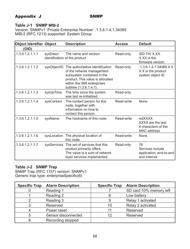
Appendix J SNMP
Table J-1 SNMP MIB-2 Version: SNMPv1 Private Enterprise Number: .1.3.6.1.4.1.34089MIB-2 (RFC 1213) supported: System Group
Object Identifier Object Description Access Default
(OID)
.1.3.6.1.2.1.1.1 sysDescr The name and version Read-only iSD-TH/ X.XXidentification of the product X.XX is the
firmware version
.1.3.6.1.2.1.1.2 sysObjectID The authoritative identification Read-only .1.3.6.1.4.1.34089.X.Xof the network management X.X is the product subsystem contained in the system object IDproduct. This value is allocated within the SMI enterprises subtree (1.3.6.1.4.1).
.1.3.6.1.2.1.1.3 sysUpTime The time since the system Read-onlywas last re-initialized.
.1.3.6.1.2.1.1.4 sysContact The contact person for this Read-write Nonenode, together with information on how to contact this person.
.1.3.6.1.2.1.1.5 sysName The hostname of this node. Read-write isdXXXXXXXX are the last 4 characters of theMAC address
.1.3.6.1.2.1.1.6 sysLocation The physical location of Read-write Nonethis node.
.1.3.6.1.2.1.1.7 sysServices The set of services that this Read-only 76product primarily offers. Services include The value is a sum of network application, end-to-end layer services implemented. and internet
Table J-2 SNMP TrapSNMP Trap (RFC 1157) version: SNMPv1Generic trap type: enterpriseSpecific(6)
Specific Trap Alarm Description Specific Trap Alarm Description
0 Reading 1 7 SD card 10% memory left1 Reading 2 8 Low battery2 Reading 3 9 Relay 1 activated3 Reserved 10 Relay 2 activated4 Power reset 11 Reserved5 Sensor disconnected 12 Reserved6 Recording stopped
68

PART 6APPROVALS INFORMATION6.1 CE APPROVAL
This product conforms to the EMC directive 89/336/EEC amended by 93/68/EEC,and with the European Low Voltage Directive 72/23/EEC.
Electrical Safety EN61010-1:2001
Safety requirements for electrical equipment for measurement, control and laboratory.Basic Insulation
Pollution Degree 2
Dielectric withstand Test per 1 min
• Input Power to Sensor Metal Body: none• Input Power to Ethernet Output: 1500Vac• Input Power to Relays: 1500Vac• Ethernet Output to Relays: 1500Vac
Measurement Category I
Category I are measurements performed on circuits not directly connected to the MainsSupply (power). Unit measures Air Temperature and Humidity.Transients Overvoltage Surge (1.2/50uS Pulse)
• Input Power: 500V Transients Overvoltage• Ethernet: 1500V Transients Overvoltage
Note: The ac/dc power adapter must have Safety Qualified Agency Approvals for CE with Double Insulation rating. The ac/dc power adapter is 9Vdc.The minimum output current rating is 500mA.
EMC EN61000-6-1:2001 (Immunity) and EN61000-6-3:2001 (Emissions)
Immunity requirements for residential, commercial and light-industrial environments • EMC Emissions Table 1, Class B • EMC Immunity Table 1: Enclosure
Table 2: Signal Lines PortsTable 3: Dc input/Dc output Ports
EMC EN61326:1997 + and A1:1998 + A2:2001
Immunity and Emissions requirements for electrical equipment for measurement, controland laboratory.
• EMC Emissions Table 4, Class B of EN61326• EMC Immunity Table 1 of EN61326
Note: I/O lines / sensor cables require shielded cables and these cables must be locatedon conductive cable trays or in conduits.
Refer to the EMC and Safety installation considerations (Guidelines) of this manual foradditional information.
6.2 FCCThis device complies with Part 15, Subpart B, Class B of the FCC rules.
69

NOTES
______________________________________________________________________________
______________________________________________________________________________
______________________________________________________________________________
______________________________________________________________________________
______________________________________________________________________________
______________________________________________________________________________
______________________________________________________________________________
______________________________________________________________________________
______________________________________________________________________________
______________________________________________________________________________
______________________________________________________________________________
______________________________________________________________________________
______________________________________________________________________________
______________________________________________________________________________
______________________________________________________________________________
______________________________________________________________________________
______________________________________________________________________________
______________________________________________________________________________
______________________________________________________________________________
______________________________________________________________________________
______________________________________________________________________________
______________________________________________________________________________
______________________________________________________________________________
______________________________________________________________________________
______________________________________________________________________________
______________________________________________________________________________

Warranty/DisclaimerNEWPORT Electronics, Inc. warrants this unit to be free of defects in materials and workmanship for a period of one(1) year from the date of purchase. In addition to NEWPORT’s standard warranty period, NEWPORT Electronics willextend the warranty period for one (1) additional year if the warranty card enclosed with each instrument is returnedto NEWPORT.
If the unit should malfunction, it must be returned to the factory for evaluation. NEWPORT’s Customer ServiceDepartment will issue an Authorized Return (AR) number immediately upon phone or written request. Uponexamination by NEWPORT, if the unit is found to be defective it will be repaired or replaced at no charge.NEWPORT’s WARRANTY does not apply to defects resulting from any action of the purchaser, including but notlimited to mishandling, improper interfacing, operation outside of design limits, improper repair, or unauthorizedmodification. This WARRANTY is VOID if the unit shows evidence of having been tampered with or shows evidenceof being damaged as a result of excessive corrosion; or current, heat, moisture or vibration; improper specification;misapplication; misuse or other operating conditions outside of NEWPORT’s control. Components which wear are notwarranted, including but not limited to contact points, fuses, and triacs.
NEWPORT is pleased to offer suggestions on the use of its various products. However, NEWPORT neitherassumes responsibility for any omissions or errors nor assumes liability for any damages that result fromthe use of its products in accordance with information provided by NEWPORT, either verbal or written.NEWPORT warrants only that the parts manufactured by it will be as specified and free of defects.NEWPORT MAKES NO OTHER WARRANTIES OR REPRESENTATIONS OF ANY KIND WHATSOEVER,EXPRESSED OR IMPLIED, EXCEPT THAT OF TITLE, AND ALL IMPLIED WARRANTIES INCLUDING ANYWARRANTY OF MERCHANTABILITY AND FITNESS FOR A PARTICULAR PURPOSE ARE HEREBYDISCLAIMED. LIMITATION OF LIABILITY: The remedies of purchaser set forth herein are exclusive and thetotal liability of NEWPORT with respect to this order, whether based on contract, warranty, negligence,indemnification, strict liability or otherwise, shall not exceed the purchase price of the component uponwhich liability is based. In no event shall NEWPORT be liable for consequential, incidental or specialdamages.
CONDITIONS: Equipment sold by NEWPORT is not intended to be used, nor shall it be used: (1) as a “BasicComponent” under 10 CFR 21 (NRC), used in or with any nuclear installation or activity; or (2) in medical applicationsor used on humans. Should any Product(s) be used in or with any nuclear installation or activity, medical application,or used on humans, or misused in any way, NEWPORT assumes no responsibility as set forth in our basicWARRANTY / DISCLAIMER language, and additionally purchaser will indemnify NEWPORT and hold NEWPORTharmless from any liability or damage whatsoever arising out of the use of the Product(s) in such a manner.
Direct all warranty and repair requests/inquiries to the NEWPORT Customer Service Department.BEFORE RETURNING ANY PRODUCT(S) TO NEWPORT, PURCHASER MUST OBTAIN ANAUTHORIZED RETURN (AR) NUMBER FROM NEWPORT’S CUSTOMER SERVICE DEPARTMENT (INORDER TO AVOID PROCESSING DELAYS). The assigned AR number should then be marked on theoutside of the return package and on any correspondence.
The purchaser is responsible for shipping charges, freight, insurance and proper packaging to preventbreakage in transit.
FOR WARRANTY RETURNS, please have thefollowing information available BEFORE contacting NEWPORT:
1. P.O. number under which the product wasPURCHASED,
2. Model and serial number of the productunder warranty, and
3. Repair instructions and/or specificproblems relative to the product.
FOR NON-WARRANTY REPAIRS, consultNEWPORT for current repair charges. Have thefollowing information available BEFORE contactingNEWPORT:
1. P.O. number to cover the COST of the repair,
2. Model and serial number of product, and3. Repair instructions and/or specific problems
relative to the product.
NEWPORT’s policy is to make running changes, not model changes, whenever an improvement is possible.This affords our customers the latest in technology and engineering.NEWPORT is a registered trademark of NEWPORT Electronics, Inc.© Copyright 2013 NEWPORT Electronics, Inc. All rights reserved. This document may not be copied,photocopied, reproduced, translated, or reduced to any electronic medium or machine-readable form, inwhole or in part, without prior written consent of NEWPORT Electronics, Inc.
Return Requests/Inquiries

M4822/N/0113