Operations Manual Contents - steamcdn-a.akamaihd.net
122
Operations Manual Flight Simulator X: Steam Edition must be correctly installed on your PC prior to the installation and use of this PA-28R Arrow III simulation. Contents INTRODUCTION ........................................................................................................ 5 Aircraft specifications .............................................................................................. 5 Paint schemes ........................................................................................................ 6 INSTALLATION .......................................................................................................... 7 SYSTEMS GUIDE ...................................................................................................... 8 Airframe .................................................................................................................. 8 Fuel system ............................................................................................................ 8 Electrical system ..................................................................................................... 9 Vacuum system .................................................................................................... 10 Pitot-static system................................................................................................. 10 Lighting system ..................................................................................................... 10 Instrument markings ............................................................................................. 11 Airspeed indicator markings .............................................................................. 11 Engine indicator markings ................................................................................. 12 Limits .................................................................................................................... 12 Weight limits ...................................................................................................... 12 Centre of gravity limits....................................................................................... 13 Manoeuvre limits ............................................................................................... 13 Flight load factor limits ...................................................................................... 13 Types of operation ............................................................................................ 13 Fuel limitations .................................................................................................. 14 Landing gear ......................................................................................................... 14 Doors and exits ..................................................................................................... 16 Flight controls ....................................................................................................... 16 Engine .................................................................................................................. 17 Engine controls ................................................................................................. 17 Engine instruments ........................................................................................... 18 Ignition and starter system ................................................................................ 18 Induction system ............................................................................................... 18 Stall warning system ............................................................................................. 18
Transcript of Operations Manual Contents - steamcdn-a.akamaihd.net
Operations Manual
Flight Simulator X: Steam Edition must be correctly installed on your PC prior to the installation and use of this PA-28R Arrow III simulation.
Contents INTRODUCTION ........................................................................................................ 5
Aircraft specifications .............................................................................................. 5
Paint schemes ........................................................................................................ 6 INSTALLATION .......................................................................................................... 7 SYSTEMS GUIDE ...................................................................................................... 8
Airframe .................................................................................................................. 8 Fuel system ............................................................................................................ 8
Electrical system ..................................................................................................... 9 Vacuum system .................................................................................................... 10
Pitot-static system ................................................................................................. 10 Lighting system ..................................................................................................... 10
Instrument markings ............................................................................................. 11 Airspeed indicator markings .............................................................................. 11 Engine indicator markings ................................................................................. 12
Limits .................................................................................................................... 12 Weight limits ...................................................................................................... 12
Centre of gravity limits ....................................................................................... 13 Manoeuvre limits ............................................................................................... 13 Flight load factor limits ...................................................................................... 13
Types of operation ............................................................................................ 13 Fuel limitations .................................................................................................. 14
Landing gear ......................................................................................................... 14
Doors and exits ..................................................................................................... 16
Flight controls ....................................................................................................... 16 Engine .................................................................................................................. 17
Engine controls ................................................................................................. 17 Engine instruments ........................................................................................... 18 Ignition and starter system ................................................................................ 18 Induction system ............................................................................................... 18
Stall warning system ............................................................................................. 18

Propeller ............................................................................................................... 19
PANEL GUIDE ......................................................................................................... 19 Panel selector ....................................................................................................... 20 Checklist panel ..................................................................................................... 21
Left main panel ..................................................................................................... 23 Left mid panel ....................................................................................................... 25 Left lower panel .................................................................................................... 26 Left sidewall .......................................................................................................... 27 Throttle quadrant .................................................................................................. 28
Right panel ........................................................................................................... 29 Centre panel ......................................................................................................... 31 Upper cockpit ........................................................................................................ 33 Lower cockpit ........................................................................................................ 34 Yoke timer ............................................................................................................ 36
KMA 20 – audio selector ....................................................................................... 37
KX 170B – COM 1 / NAV 1 radio .......................................................................... 38 COM controls .................................................................................................... 38
NAV controls ..................................................................................................... 39 KX 175B – COM 2 / NAV 2 radio .......................................................................... 39 KT 76A – transponder ........................................................................................... 39
Operating the KT 76A ....................................................................................... 39 Important codes ................................................................................................ 40 Squawk ident..................................................................................................... 40
Reply light ......................................................................................................... 40 GPS 100 – GPS unit ............................................................................................. 41
Self-test page .................................................................................................... 42 Initialisation page .............................................................................................. 42 Satellite status page .......................................................................................... 42
Active route page .............................................................................................. 43
Go-to page ........................................................................................................ 44 Nearest intersection page ................................................................................. 44 CDI page ........................................................................................................... 45 Present position page ....................................................................................... 45
Density altitude and TAS page .......................................................................... 46 Wind aloft page ................................................................................................. 46 Fuel planning page ............................................................................................ 47 Message page................................................................................................... 47
KN 62A – DME ..................................................................................................... 48
Frequency mode ............................................................................................... 49 Groundspeed/Time-to-Station mode ................................................................. 49 Remote mode.................................................................................................... 49
KR 85 – ADF ........................................................................................................ 50
Frequency selection .......................................................................................... 50 Operating modes ............................................................................................... 50 ADF test ............................................................................................................ 51
Towbar panel ........................................................................................................ 51 Flight computer ..................................................................................................... 52 Logbook ................................................................................................................ 53
AUTOPILOT ............................................................................................................. 54 Controls ................................................................................................................ 55

Navigation/approach coupler ............................................................................ 55
Coupler radio selector switch ............................................................................ 55 Heading bug ...................................................................................................... 56
Operation .............................................................................................................. 56
Pre-flight ground check ..................................................................................... 56 Preselect ........................................................................................................... 56 Coupler ............................................................................................................. 57 Engaging in flight ............................................................................................... 57 Use of heading hold and preselect .................................................................... 57
Use of roll command function ............................................................................ 57 Override ............................................................................................................ 57
Operation of coupler ............................................................................................. 58 Intercepting VOR radials ................................................................................... 58 VOR navigation ................................................................................................. 58
VOR approach .................................................................................................. 59
ILS approach ..................................................................................................... 60 ILS back course approach ................................................................................ 60
Checklist ............................................................................................................... 61 Engaging roll command .................................................................................... 61 Engaging heading preselect .............................................................................. 61
Engaging radio coupling .................................................................................... 61 GROUND EQUIPMENT ........................................................................................... 62 REFILL MENU ......................................................................................................... 63
FAILURES ................................................................................................................ 64 MENU BAR OPTIONS ............................................................................................. 65
Automatic fuel selector ......................................................................................... 66 Fuel pump / gyro sounds ...................................................................................... 66 Engine management ............................................................................................. 66
Panel selector ....................................................................................................... 67
FLYING THE ARROW ............................................................................................. 67 Getting started ...................................................................................................... 69 Starting the engine................................................................................................ 78 Configuring the avionics ....................................................................................... 85
Taxi ....................................................................................................................... 88 Take-off ................................................................................................................ 92 Climb .................................................................................................................... 93 Cruise ................................................................................................................... 96 Descent .............................................................................................................. 103
Approach and landing ......................................................................................... 104 Shutdown ............................................................................................................ 107
NORMAL PROCEDURES ...................................................................................... 108 Airspeed (IAS) for safe operations ...................................................................... 108
Pre-flight ............................................................................................................. 109 Cockpit ............................................................................................................ 109 Left/right wing .................................................................................................. 109
Nose section ................................................................................................... 109 Tail section ...................................................................................................... 109
Before starting engine ......................................................................................... 110 Engine starting .................................................................................................... 110
Cold engine ..................................................................................................... 110

Hot engine ....................................................................................................... 111
Taxiing ................................................................................................................ 111 Ground check ..................................................................................................... 111 Before take-off .................................................................................................... 112
Take-off .............................................................................................................. 112 Normal technique ............................................................................................ 112 Short field/obstacle clearance technique ......................................................... 113
Cruise ................................................................................................................. 113 Descent .............................................................................................................. 114
Approach and landing ......................................................................................... 114 Shutdown ............................................................................................................ 114 Stalls ................................................................................................................... 115
EMERGENCY PROCEDURES .............................................................................. 115 Airspeed (IAS) for safe operations ...................................................................... 115
Engine failures .................................................................................................... 116
Engine failure during start ............................................................................... 116 Engine failure in flight ...................................................................................... 116
Power off landing ................................................................................................ 117 Gear up emergency landing ............................................................................ 118
Fires .................................................................................................................... 118
Engine fire in flight ........................................................................................... 118 Electrical fire.................................................................................................... 118
Low oil pressure.................................................................................................. 119
Low fuel flow/pressure ........................................................................................ 119 Propeller governor failure ................................................................................... 119
Electrical failures................................................................................................. 119 Icing .................................................................................................................... 120 Emergency landing gear extension..................................................................... 120
Spin recovery ...................................................................................................... 121
Airspeed indicating system failure ...................................................................... 121 CREDITS ............................................................................................................... 121 COPYRIGHT .......................................................................................................... 122

INTRODUCTION The PA-28R Arrow III is a four-seat, piston-engine aircraft equipped with retractable tricycle landing gear and a constant-speed propeller – an ideal aircraft for touring and instrument training. The origins of the Arrow start with the Piper Cherokee, which began production in 1961. The Cherokee was introduced as a more affordable alternative to Piper’s Comanche and to compete with the popular Cessna 172. Piper introduced the original Cherokee Arrow in 1967 and it was the first of the Cherokee family to feature retractable landing gear. The Arrow II followed in 1972 with a stretched fuselage to provide increased leg room for the rear passengers, and the Arrow III arrived in 1977 with larger fuel tanks for improved range and a semi-tapered wing and longer stabilator for improved low-speed handling. Over 6,000 PA-28Rs have been built and the Arrow III continues to be flown all around the world.
Aircraft specifications Dimensions Length 7.5 m (24.7 ft) Wingspan 10.8 m (35.4 ft) Height (to top of tail) 2.4 m (7.9 ft) Wing area 15.8 m2 (170 ft2)
Engine Type Lycoming IO-360 four cylinder, horizontally opposed piston Power 200 horsepower Propeller Three-blade, constant-speed, hydraulically actuated
Weights Empty weight 1,612 lb (731 kg) Maximum take-off/landing weight 2,750 lb (1,247 kg) Maximum baggage weight 200 lb (91 kg) Maximum useful load 1,148 lb (521 kg)

Fuel and oil Fuel capacity 77 US gallons Usable fuel 72 US gallons Oil capacity 8 US quarts
Performance
VNE (never exceed speed) 183 KIAS VNO (max. cruising speed) 146 KIAS VA (manoeuvring speed) 118 KIAS (at 2,750 lb) 96 KIAS (at 1,865 lb) VFE (max. flap speeds) 103 KIAS VLE (max. gear extension speed) 129 KIAS VSO (stall speed) 55 KIAS (landing configuration) Service ceiling 15,000 ft Range (max. payload) 697 nautical miles
Paint schemes The Arrow III is supplied in the following 11 paint schemes:
G-BGKU (UK)
C-GQYI (Canada)
N4131C (USA)
G-BNSG (UK)
F-GJCB (France)
HB-PJA (Switzerland)
VH-SGE (Australia)
D-ERIN (Germany)
G-TEBZ (UK)
G-TSGA (UK)
N751LU (USA)

INSTALLATION Installation is handled by Steam after purchase of the product. After purchasing the product the files will be downloaded and installation into the Scenery Library will be automatic.
Accessing the aircraft
1. Click on ‘Free Flight’. 2. Select ‘Just Flight’ from the ‘Publisher’ drop-down menu. 3. Select ‘Piper’ from the Manufacturer drop-down and choose one of
the schemes. Tick the ‘Show all variations’ box to see all the available paint schemes.
Updates
Updates to the product will automatically be deployed, downloaded and installed via Steam to all users who own the product.
Technical Support To obtain technical support (in English) please visit the Support pages at justflight.com. As a Just Flight customer you can obtain free technical support for any Just Flight or Just Trains product. For support specifically on the Steam version of the add-on please contact Dovetail Games. https://dovetailgames.kayako.com
Regular News To get the latest news about Just Flight products, sign up for our Newsletter.

SYSTEMS GUIDE
Airframe The PA-28R-201 Arrow III is a single-engine, all-metal aircraft with retractable landing gear. It has seating for up to four occupants, a 200-pound luggage compartment and a 200 HP engine. The basic airframe is constructed out of aluminium alloy. Aerobatics are prohibited in this aircraft since the structure is not designed for aerobatic loads. The fuselage is a semi-monocoque structure. There is a front door on the right side and a cargo door is installed aft of the rear seat. The wing is of conventional semi-tapered design and employs a laminar flow NACA 652-415 airfoil section. The main spar is located at approximately 40% of the chord aft of the leading edge. The rear spar, in addition to taking torque and drag loads, provides a mount for flaps and ailerons. The four-position wing flaps are mechanically controlled by a handle located between the front seats. When fully retracted, the right flap locks into place to provide a step for cabin entry. Each wing contains one fuel tank. A vertical stabiliser, an all-movable horizontal stabilator and a rudder make up the empennage. The stabilator incorporates an anti-servo tab which improves longitudinal stability and provides longitudinal trim. This tab moves in the same direction as the stabilator but with increased travel.
Fuel system The fuel system was designed with simplicity in mind. Fuel is contained in two 38.5 US gallon tanks, one in each wing. Of the total 77-gallon capacity, only 72 gallons are usable. The tanks are attached to the leading edge of the wing with screws and are an integral part of the wing structure. A fuel tank selector allows the pilot to control the flow of fuel to the engine and is located on the left sidewall below the instrument panel. It has three positions: OFF, LEFT TANK and RIGHT TANK. The arrow on the handle of the selector points to the tank which is supplying fuel to the engine. Normally fuel is supplied to the engine through an engine-driven fuel pump. An electric fuel pump serves as a back-up feature. The electric fuel pump is controlled by a rocker switch on the switch panel above the engine control quadrant. The

electric fuel pump should be ON when switching fuel tanks and during take-offs and landings. Fuel quantity and flow/pressure are indicated on gauges on the instrument panel. There is a separate fuel quantity gauge for each tank.
Electrical system All switches are grouped in a switch panel above the throttle quadrant. The circuit breaker panel is located on the lower right side of the instrument panel. Each breaker is clearly marked to show which circuit it protects. Standard electrical accessories include alternator, starter, electric fuel pump, stall warning horn, ammeter and annunciator panel. The annunciator panel includes alternator, low oil pressure and low vacuum indicator lights. The annunciator panel lights are provided only as a warning to the pilot that a system may not be operating properly, and that they should check and monitor the applicable system gauge to determine when or if action is required. The primary electrical power source is a 14-volt, 60-amp alternator which is protected by an alternator control unit that incorporates a voltage regulator and an over-voltage relay. The alternator provides full electrical power output even at low engine RPM. This provides improved radio and electrical equipment operation and increases battery life by reducing battery load. Secondary power is provided by a 12-volt, 35-ampere-hour battery. The ammeter as installed does not show battery discharge; rather it shows the electrical load placed on the system. With all the electrical equipment off, and the battery master (BATT MASTR) and alternator (ALT.R) switches on, the ammeter will indicate the charging rate of the battery. As each electrical unit is switched on, the ammeter will indicate the total ampere draw of all the units, including the battery. For example, the average continuous load for night flying with radios on is about 30 amperes. The 30 ampere value plus 2 amperes for charging the battery will then show on the ammeter, indicating the alternator is functioning properly.

Vacuum system The vacuum system is designed to operate the air-driven gyro instruments. This includes the directional and attitude gyros when installed. The system consists of an engine vacuum pump, a vacuum regulator, a filter and the necessary plumbing. The vacuum gauge, mounted on the right instrument panel, provides valuable information to the pilot about the operation of the vacuum system. A decrease in pressure, or zero pressure, over an extended period may indicate a problem with the vacuum system. A vacuum regulator is provided in the system to protect the gyros. The valve is set so the normal vacuum reads 4.8 to 5.1 inches of mercury, a setting which provides sufficient vacuum to operate all the gyros at their rated RPM.
Pitot-static system The system supplies both pitot and static pressure for the airspeed indicator, altimeter and vertical speed indicator. Pitot pressure is picked up by the pitot head on the bottom of the left wing. The switch for pitot heat is located on the switch panel. Static pressure is sensed by button-type vents on each side of the aft fuselage. Push-button-type pitot and static drains are located on the lower left sidewall of the cockpit.
Lighting system Lights fitted to the aircraft include navigation, anti-collision, landing, instrument panel and cabin dome lights. The navigation lights are controlled by a rocker switch on the main switch panel. Radio, panel and switch lights are controlled by rheostat switches located below and to the right of the pilot’s yoke, adjacent to the engine instruments. A light mounted in the overhead panel provides instrument and cockpit lighting for night flying. The light is controlled by a rheostat switch located adjacent to the light. The anti-collision and landing lights are controlled by rocker switches on the main switch panel.

Instrument markings
Airspeed indicator markings
MARKING KIAS
VALUE OR RANGE SIGNIFICANCE
White arc 55-103
Full flap operating range.
Lower limit is maximum
weight VSO in landing
configuration. Upper limit
is maximum speed
permissible with flaps
extended.
Green arc 60-146
Normal operating range.
Lower limit is maximum
weight VS1 with flaps
retracted. Upper limit is
maximum structural
cruising speed.
Yellow arc 146-183
Operations must be
conducted with caution
and only in smooth air.
Red line 183 Maximum speed for all
operations.

Engine indicator markings
INSTRUMENT Red line or arc
Minimum limit
Yellow arc
Caution range
Green arc
Normal
operating
Red line
Maximum
limit
Tachometer ---------- ---------- 500-2,700
RPM 2,700 RPM
Oil temperature ---------- ---------- 75-245°F
(24-118°C)
245°F
(118°C)
Fuel pressure
Fuel flow ---------- ----------
0.05-12
PSI
2-21.4
gal/hr
12 PSI
21.4 gal/hr
Oil pressure 25 PSI
25-60 PSI (idle)
and
90-100 PSI
(start/warm-up)
60-90 PSI 100 PSI
Vacuum gauge ---------- ---------- 4.8-5.1
inHG 6.0 inHG
Limits
Weight limits Maximum weight: 2,750 lb (1,247 kg) Maximum weight in baggage compartment: 200 lb (91 kg)

Centre of gravity limits
Weight
(lb)
Forward limit
Inches aft of
datum
Rearward limit
Inches aft of
datum
2,750 88.9 91.5
2,375 and below 82.0 91.5
The datum used is 78.4 inches ahead of the wing leading edge at the intersection of the straight and tapered section.
Manoeuvre limits This aircraft is certificated in the normal category. The normal category is applicable to aircraft intended for non-aerobatic operations. These include any manoeuvres incidental to normal flying, stalls (except whip stalls), lazy eights, chandelles and steep turns in which the angle of bank is no more than 60° and pitch is no more than 30°. Aerobatic manoeuvres, including spins, are not approved.
Flight load factor limits Positive load factor (maximum): + 3.8 G Negative load factor (maximum): No inverted manoeuvres approved
Types of operation The aircraft is approved for the following operations:
Day VFR
Night VFR
Day IFR
Night IFR
Non-icing
Fuel limitations Total capacity: 77 US gallons Unusable fuel: 5 US gallons (2.5 gallons per wing tank) Usable fuel: 72 US gallons (36 gallons per wing tank)
Landing gear The Arrow is equipped with retractable tricycle landing gear which is hydraulically actuated by an electrically powered reversible pump. The pump is controlled by a selector switch on the instrument panel, to the left of the control quadrant. The landing gear is retracted or extended in about seven seconds. For emergency gear extension, the emergency gear lever, located between the front seats to the left of the flap handle, must be in the down position to manually release hydraulic pressure and permit the gear to freefall. The nose gear is spring-assisted. The aircraft is fitted with an automatic gear extension system. The system automatically extends the landing gear when engine power is reduced with the airspeed at or below approximately 87 KIAS. The system is triggered by differential air pressure sensed by a static source mast on the left side of the fuselage. The emergency gear lever can also be used to override the automatic gear extension system. The lever has three positions:
UP – automatic extension system overridden. Used for situations such as take-off, practising stalls and low speed handling, and for maximising glide ratio. AUTO EXT OFF light flashes.
MID – automatic extension system enabled. Landing gear will automatically extend when power is reduced below 14 inches of manifold pressure and airspeed drops below 87 KIAS.
DOWN – push down for manual emergency gear extension when below 87 KIAS.
Gear down and locked positions are indicated by three green lights located to the left of the selector. A red WARNING GEAR UNSAFE light, located at the top of the panel, illuminates while the gear is in transit, or not in the fully up or locked down position. An all lights out condition indicates that the gear is up. The landing gear should not be retracted above a speed of 107 KIAS and should not be extended above a speed of 129 KIAS. A microswitch in the throttle quadrant activates a warning horn and red WARNING GEAR UNSAFE light under the following conditions:
a. Gear up and power reduced below approximately 14 inches of manifold pressure, or automatic extension triggered and gear handle in UP position.
b. Gear selector switch UP while on the ground and throttle in retarded position. c. Whenever the flaps are extended beyond the approach position (10°) and the
landing gear is not down and locked.
The gear warning horn emits a 90Hz beeping sound, in contrast to the stall warning horn which emits a continuous sound. The nose gear is steerable through a 30-degree arc each side of centre by use of the rudder pedals. As the nose wheel retracts, the steering linkage disengages to reduce rudder pedal loads in flight. The nose wheel is equipped with a hydraulic shimmy damper to reduce nose wheel shimmy. A bungee assembly is also included to reduce ground steering effort and to dampen shocks and bumps during taxiing. The standard brake system includes toe brakes on the left and right set of rudder pedals and a hand brake located below and near the centre of the instrument panel. The toe brakes and the hand brake have individual brake cylinders, but all cylinders use a common reservoir. The parking brake is incorporated in the lever brake and is operated by pulling back on the lever and depressing the knob attached to the top of the handle. To release the parking brake, pull back on the brake lever and then allow the handle to swing forward.

Doors and exits The aircraft is fitted with a passenger door and a baggage door. To open the passenger door, press [Shift]+[E]. To open the baggage door, press [Shift]+[E] then [2]. The passenger door can be opened from within the virtual cockpit by clicking on the two door latches to rotate them to the OPEN position and then clicking on the door frame to push it open. It can be closed by clicking on the door frame to pull it closed and then clicking on the two door latches to rotate them to the LATCH position. Note: If both latches are not rotated to the LATCH position, the passenger door will not shut fully and significant wind noise will enter the cabin at higher airspeeds. The engine inspection door can be opened by moving the ELT switch on the left sidewall to the ON (up) position. The door can be shut by moving the switch to the AUTO/ARM or OFF/RESET position.
Flight controls Dual flight controls are provided as standard equipment. A cable system provides actuation of the control surfaces when the flight controls are moved. The horizontal surface (stabilator) features a trim tab/servo mounted on the trailing edge. This tab serves the dual function of providing trim control and pitch control forces. The trim function is controlled by a trim control wheel located on the control console between the two front seats. Rotating the wheel forward gives nose-down trim and rotation aft gives nose-up trim. The rudder is conventional in design and incorporates a rudder trim. The trim mechanism is a spring-loaded recentring device. The trim control is located on the right side of the pedestal below the throttle quadrant. Turning the trim control clockwise results in nose-right trim and anti-clockwise rotation results in nose-left trim. Manually controlled flaps are provided. They are extended by a control cable and are spring-loaded to the retracted (up) position. The control is located between the two front seats on the control console. To extend the flaps, pull the handle up to the desired flap setting of 10, 25 or 40 degrees. To retract, depress the button on the end of the handle and lower the control. The aircraft will experience a pitch change during flap extension or retraction. This pitch change can be corrected by either stabilator trim or increased control wheel force. When the flaps are in the retracted position the right flap, provided with an over-centre lock mechanism, acts as a step.

Engine The Arrow is powered by a Lycoming I0-360 four-cylinder, direct drive, horizontally opposed fuel-injected engine, rated at 200 horsepower at 2,700 RPM. It is fitted with a starter, 60-ampere 14-volt alternator, ignition, vacuum pump drive, fuel pump, propeller governor and an induction air filter. The aircraft is equipped with a constant speed, controllable-pitch propeller. The propeller control is located on the throttle quadrant between the throttle and mixture controls. A mixture control lock is provided to prevent activation of the mixture control instead of the pitch control. Left-click on the lock to disengage or engage it. With the lock engaged, the mixture lever cannot be moved below approximately 40%. An oil cooler is located on the forward lower right side of the firewall, with the air inlet for the cooler located on the right side of the bottom cowling.
Engine controls The engine controls consist of a throttle control, a propeller control and a mixture control lever. These controls are located on the control quadrant on the lower centre of the instrument panel, where they are accessible to both the pilot and the co-pilot. The throttle lever is used to adjust the manifold pressure. It incorporates a gear-up warning horn switch which is activated during the last portion of travel of the throttle lever to the low power position. If the landing gear is not locked down, the horn will sound until the gear is down and locked or until the power setting is increased. This is a safety feature to warn of an inadvertent gear-up landing. The propeller control lever is used to adjust the propeller speed from high RPM to low RPM. The mixture control lever is used to adjust the air-to-fuel ratio. The engine is shut down by placing the mixture control lever in the fully lean position. In addition, the mixture control has a lock to prevent activation of mixture control instead of pitch control. The alternate air control is located to the right of the control quadrant. When the alternate air lever is in the up (closed) position, the engine is operating on filtered air. When the lever is in the down (open) position, the engine is operating on unfiltered, heated air.

Engine instruments Indicators enable the pilot to check oil pressure, oil temperature, tachometer, manifold pressure, fuel flow and EGT. The engine instruments are located on the mid and lower portions of the left panel and the lower portion of the right panel.
Ignition and starter system Engine ignition is provided by a dual magneto on two spark plugs per cylinder. Ignition is controlled by a key-operated rotating selector on the lower left portion of the left panel. The selector operates clockwise, with right, left, left/right and start positions.
Induction system The induction system incorporates a fuel injector. The injector is based on the principle of differential pressure, which balances air pressure against fuel pressure. The regulated fuel pressure established by the servo valve when applied across a fuel control makes the fuel flow proportional to air flow. The fuel flow portion of the manifold pressure/fuel flow gauge is connected to a flow divider and monitors fuel pressure. This instrument converts fuel pressure to an indication of fuel flow in gallons per hour and percentage of rated horsepower. The alternate air source of the induction system contains a door that functions automatically or manually. If the primary source is obstructed, the door will open automatically. It may be opened manually by moving the selector on the right side of the quadrant. The primary source should always be used for take-off.
Stall warning system An approaching stall is indicated by a stall warning horn which is activated between five and ten knots above stall speed. Mild airframe buffeting and gentle pitching may also precede the stall. Stall speeds are shown on graphs in the OPERATING DATA MANUAL. The stall warning horn emits a continuous sound, in contrast to the gear warning horn which emits a 90Hz beeping sound. The stall warning horn is activated by a lift detector installed on the leading edge of the left wing. The battery master (BATT MASTR) switch must be ON for the stall warning system to function.

Propeller The aircraft is fitted with an all-metal, three-blade, constant-speed, governor-regulated propeller. The propeller control actuates on the governor. According to the control position, the governor determines propeller rotation speed and thus the engine speed to be maintained. The governor controls the flow of engine oil, boosted to high pressure by the governing pump, onto a piston located in the propeller hub. Oil pressure twists the blades toward high pitch (low RPM). When oil pressure to the piston is relieved, the blades twist to low pitch (high RPM).
PANEL GUIDE
The instrument panel is designed to accommodate the customary advanced flight instruments and the normally required power plant instruments. The altitude and directional gyros, located in the centre of the left-hand instrument panel, are vacuum-operated. The vacuum gauge is located on the right-hand instrument panel. The turn indicator on the left side is electrically operated. The radios are located in the centre section of the panel and the circuit breakers are in the lower right corner of the panel. An annunciator panel is mounted in the upper instrument panel to warn the pilot of a possible malfunction in the alternator, oil pressure or vacuum systems. Additional features include a pilot storm window and two sun visors. The cabin door is double-locked. To close the cabin door, hold the door closed with the armrest while moving the side door latch to the LATCHED position, then engage the top latch. Both latches must be secured before flight. A large baggage area, located behind the rear seats, is accessible either from the cabin or through a large outside baggage door on the right side of the aircraft. It is the pilot’s responsibility when baggage is loaded to be sure that the aircraft’s centre of gravity falls within the allowable CG range.

Panel selector The panel selector arrow appears in the top left corner of the screen every time you
load the Arrow III:
Left-click on this arrow to open the panel selector:
You can use the panel selector to open the 2D panels:
Checklist
Flight computer
Logbook
Towbar control
Simply place your mouse cursor over the panel that you want to open (the panel will
turn a darker shade of grey to make it easier to see which one you are about to
select) and then left-click on it. It will turn red to indicate that it’s open and the
relevant 2D panel will appear. A tooltip will appear to indicate which panel/function
the icon corresponds to.
The cross in the top left corner closes the panel selector and reverts to the arrow.

Checklist panel In addition to the checklists in this manual, an interactive checklist is included in the
aircraft as a 2D pop-up panel which can be accessed by clicking on the appropriate
symbol on the panel selector.

1. Checklist name – in the top left corner of the panel is the name of the currently
selected checklist, for example ‘Before Take-off’.
2. Checklist items – the checklist items are displayed in the centre of the panel.
When the panel is first opened, or when a new checklist is selected, the items will
appear in red text. Click on the checklist item when you have completed the
relevant action/check and the item text will turn green to indicate that the item is
complete. Hover over longer checklist items to see all of the text.
3. Checklist navigation buttons – at the bottom of the panel are four buttons. These
allow you to cycle through the available checklists and select the previous/next
page of the selected checklist. The button will be greyed out if it is not active.
4. Current page number – the checklist page number is displayed in the bottom right
corner if there are multiple pages.
An interactive engine start checklist can be accessed by clicking on the icon in the
lower left corner of the Checklist panel when either the 'Before Start' or 'Engine Start'
checklist is selected.
The checklist items will automatically turn from red to green when you have
completed the associated check. The failures section displays the status of possible
failures that will prevent engine starting. The failure items will automatically change
from green to red if the associated failure occurs.

Left main panel
Vacuum gauge
1. Airspeed indicator (ASI) – a true airspeed indicator is incorporated into the
airspeed indicator. The true airspeed indicator consists of a rotatable ring which
is controlled using the knob located below the ASI. To set the indicator, rotate the
ring until the pressure altitude is aligned with the outside air temperature (OAT).
To obtain the pressure altitude, set the barometric scale of the altimeter to 29.92
inHG / 1013.2 hPa and then read the pressure altitude. With the ring set, the true
airspeed can be read along the bottom scale.
2. Attitude indicator (AI) – a pitch reference knob allows for the pitch bars (aircraft
symbol) position to be adjusted nose-up or nose-down.
3. Gear unsafe warning light – illuminates while the gear is in transit, or not in the
fully up or locked down position. Refer to the Landing gear section of this manual
for more information.
4. Starter engaged light
5. Altimeter – a barometric pressure scale is provided for hPa/mb. The pressure
setting knob tooltip displays the currently selected pressure in hPa/mb or inHG,
depending on which unit of measurement is currently active in the simulator
settings.
6. Annunciator press-to-test button – press to test annunciator lights
7. Annunciator lights
8. VOR 1 / ILS indicator – driven by KX 170B (or Flight1 GTN if installed)
9. Low voltage warning light

10. ADF indicator – driven by KR 85 ADF system. HDG knob controls rotation of the
compass card.
11. Turn and bank indicator
12. Direction indicator – caging knob (bottom left) controls rotation of the compass
card. HDG knob (bottom right) controls the heading bug.
13. Vertical speed indicator (VSI)
14. VOR 2 indicator – driven by KX 175B

Left mid panel
1. Oil pressure indicator
2. Oil temperature indicator
3. Ammeter
4. Yoke toggle click-spot (same location on right yoke)
5. Left fuel tank quantity indicator
6. Fuel pressure indicator
7. Right fuel tank quantity indicator

Left lower panel
1. Autopilot controls – refer to the AUTOPILOT section for more information.
2. Electric pitch trim push-button – push in to enable the electric pitch trim (rocker
switch located on yoke).
3. Magneto/start selector
4. Manifold pressure (inHG) and fuel flow / fuel pressure (gallons per hour / PSI)
5. Tachometer (RPM)
6. Landing gear lever
7. Automatic gear extension warning light
8. Gear position lights

Left sidewall
1. Fuel tank selector
2. Emergency locator transmitter switch
3. Storm window (note that the latch must be moved prior to opening/closing the
window)

Throttle quadrant
1. Throttle lever
2. Propeller control lever
3. Mixture lever – the mixture lever is fitted with a lock. Left-click on the lock to
disengage or engage it. The lock must be disengaged before the lever can be
moved below 40%.
4. Friction control

Right panel
1. Intercom switch
2. DME selector switch – selects whether the KX 170B (or Flight1 GTN if installed)
or KX 175B is used as the input to the KN 62.
3. GPS 100
4. KN 62A DME
5. KR 85 ADF

6. Standby altimeter – a barometric pressure scale is provided for hPa/mb. The pressure setting knob tooltip displays the currently selected pressure in hPa/mb or inHG, depending on which unit of measurement is currently active in the simulator settings.
7. DATCON hour meter
8. Heating control levers
9. Fan control switch
10. Circuit breaker panel

Centre panel

1. KMA 20 audio selector
2. KX 170B COM 1 / NAV 1 radio
3. KX 175B COM 2 / NAV 2 radio
4. KT 76A transponder
5. Navigation and radio light switch
6. Battery master and alternator switches
7. Fuel pump switch
8. Landing light switch
9. Rotating beacon and anti-collision lights switches
10. Pitot heat switch
11. Panel lights switch
12. Exhaust gas temperature (EGT) indicator – rotate screw to control the position of
the red (maximum value) needle.
13. Alternate air control lever
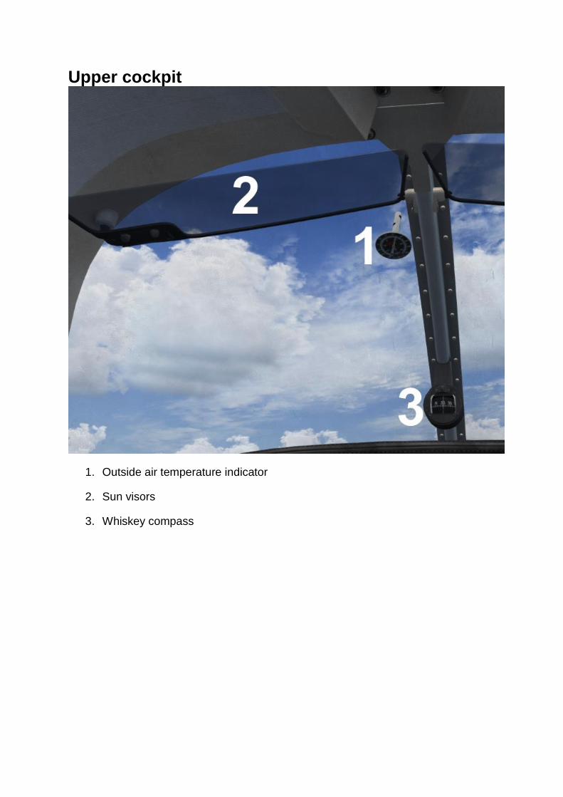
Upper cockpit
1. Outside air temperature indicator
2. Sun visors
3. Whiskey compass

Lower cockpit
1. Parking brake handle
2. Rudder trim knob and indicator – turning the trim control clockwise results in
nose-right trim and anti-clockwise rotation results in nose-left trim.

3. Flap lever
4. Emergency gear lever – refer to the Landing gear section for more
information.
5. Elevator trim wheel and indicator – rotating the wheel forward gives nose-
down trim and rotation aft gives nose-up trim.

Yoke timer
1. Timer display
2. Reset button
3. Mode button
4. Start/Stop button
The yoke is fitted with a digital chronometer. The mode button allows you to toggle
between either clock mode or timer mode.
With timer mode selected, the start/stop and reset buttons can be used to control the
timer. Press the reset (RST) button so that the time reads zero and then press the
start/stop (ST-SP) button to start and stop the timer. The timer will count in minutes
and seconds until 59 minutes and 59 seconds, at which point the timer will change to
count in hours and minutes.
With clock mode selected, the current local time will be shown in hours and minutes.

KMA 20 – audio selector
1. Microphone selector switch
2. AUTO switch
3. Receiver selector switches
4. Marker beacon sensitivity and lamp test switch
5. Marker beacon lights
The KMA 20 is an audio control system which provides control over transceiver and receiver outputs through the use of selector switches. The simulator doesn’t allow for separate speaker and headphone outputs so both buttons perform the same function. The COM 1 and COM 2 switches are used to toggle the COM 1 and COM 2 transceiver audio, allowing you to select COM 1 and/or COM 2 as the audio sources to monitor. The NAV, DME, MKR and ADF switches are used to toggle the associated audio sources. When the AUTO switch is placed in either the SPEAKER or PHONE position, the unit will automatically match the corresponding receiver audio with the selected transmitter. For example, with COM 1 selected on the microphone selector knob, the COM 1 audio source will be automatically enabled. The microphone selector knob connects the microphone to the selected output. Due to simulator limitations, transmissions can only be made on COM 1.
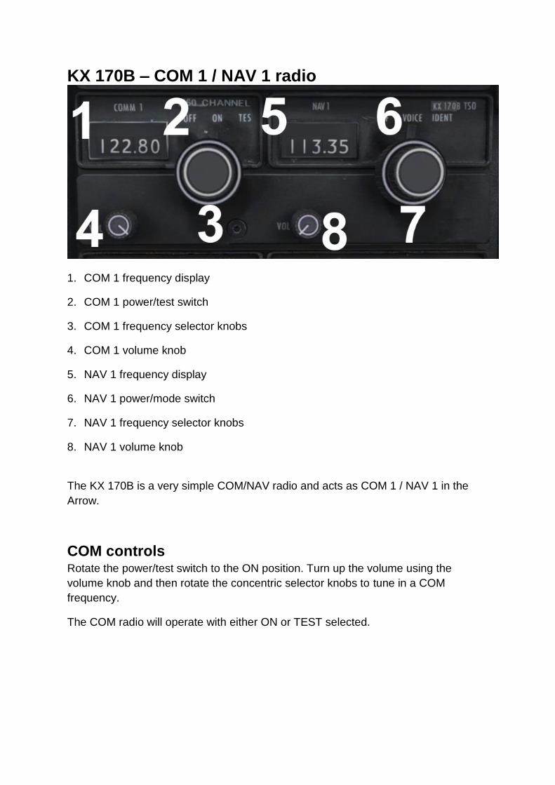
KX 170B – COM 1 / NAV 1 radio
1. COM 1 frequency display
2. COM 1 power/test switch
3. COM 1 frequency selector knobs
4. COM 1 volume knob
5. NAV 1 frequency display
6. NAV 1 power/mode switch
7. NAV 1 frequency selector knobs
8. NAV 1 volume knob
The KX 170B is a very simple COM/NAV radio and acts as COM 1 / NAV 1 in the
Arrow.
COM controls Rotate the power/test switch to the ON position. Turn up the volume using the
volume knob and then rotate the concentric selector knobs to tune in a COM
frequency.
The COM radio will operate with either ON or TEST selected.

NAV controls Rotate the power/mode switch to the VOICE position. Turn up the volume using the
volume knob and then rotate the concentric selector knobs to tune in a NAV
frequency.
Rotate the power/mode switch to the IDENT position to hear the audio identifier.
KX 175B – COM 2 / NAV 2 radio The KX 175B is identical in operation to the KX 170B and acts as COM 2 / NAV 2 in
the Arrow.
KT 76A – transponder
1. Function selector knob
2. Reply light
3. Identification push-button
4. Code windows
5. Code knobs
Operating the KT 76A The function selector knob should be in the OFF position before starting the aircraft’s
engine. Select the required reply code by rotating the four code knobs (one per code
digit). The code will be displayed in the four code windows.
After starting the engine, turn the function selector to standby (SBY). The
transponder will take approximately 45-50 seconds to become operational. Once
airborne, turn the function selector to ON, enabling normal Mode A operation.
Turn the function selector to the altitude (ALT) position for altitude reporting (Mode
C) to ATC.

Important codes 7700: Emergency
7600: Communications failure
7500: Hijacking
0000: Reserved for military aircraft
Squawk ident When you are asked to ident by ATC, press and release the ident push-button. Your
aircraft will be positively identified to the air traffic controller.
Reply light During normal operation, the reply light will flash to indicate that the KT 76A is
functioning properly and replying to interrogations from ground radar. Interrogations
occur at 10-15 second intervals, corresponding to each radar sweep.
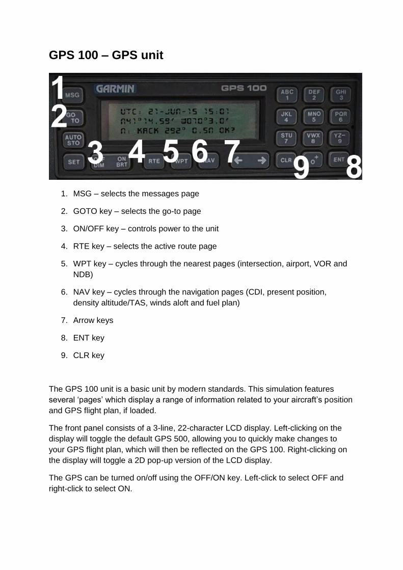
GPS 100 – GPS unit
1. MSG – selects the messages page
2. GOTO key – selects the go-to page
3. ON/OFF key – controls power to the unit
4. RTE key – selects the active route page
5. WPT key – cycles through the nearest pages (intersection, airport, VOR and
NDB)
6. NAV key – cycles through the navigation pages (CDI, present position,
density altitude/TAS, winds aloft and fuel plan)
7. Arrow keys
8. ENT key
9. CLR key
The GPS 100 unit is a basic unit by modern standards. This simulation features
several ‘pages’ which display a range of information related to your aircraft’s position
and GPS flight plan, if loaded.
The front panel consists of a 3-line, 22-character LCD display. Left-clicking on the
display will toggle the default GPS 500, allowing you to quickly make changes to
your GPS flight plan, which will then be reflected on the GPS 100. Right-clicking on
the display will toggle a 2D pop-up version of the LCD display.
The GPS can be turned on/off using the OFF/ON key. Left-click to select OFF and
right-click to select ON.

Self-test page
The first page to be displayed is the self-test page. The unit will carry out a self-test
which should take a couple of seconds.
The initialisation page will then be displayed.
Initialisation page
The initialisation page shows the current UTC time and date, latitude and longitude, nearest airport, and the bearing and distance (in nautical miles) to that airport.
Satellite status page Press the ENT (enter) key to bring up the satellite status page. The GPS will go through the process of acquiring satellites.
The receiver status is shown in the top left of the page:

SEARCH SKY – the GPS 100 is in the process of searching the sky for visible satellites. ACQUIRING – the GPS 100 is in the process of acquiring visible satellites. 3D NAV – the GPS 100 is acquiring enough satellites to begin navigation. Note: The GPS 100 will only display navigation information when the status is 3D NAV. The estimated position error (in feet) is shown in the top right of the page and this will decrease as more satellites are acquired. The unique ID character for each of the satellites is shown on the second line and the signal strength (from 0 to 9) is shown on the third line.
Active route page
The active route page shows information regarding the GPS flight plan (if one is loaded):
Flight plan origin and destination ICAO
Waypoint name, distance (nautical miles) and estimated time en route The arrow keys can be used to scroll through the list of waypoints in the flight plan.

Go-to page
The go-to page shows you information related to the next waypoint in your flight plan:
Previous waypoint and next waypoint name
Groundspeed (knots)
Range to next waypoint (nautical miles)
Desired track to next waypoint
Cross-track distance (nautical miles)
Estimated time en route (hours/minutes)
Nearest intersection page
The nearest intersection page shows the nine closest waypoints – intersections, airports, VORs and NDBs. The name, bearing and distance (in nautical miles) to each waypoint is shown. Use the arrow keys to scroll through the list of nine waypoints and press the WPT key to cycle through the waypoint types (intersections, airports etc.). Note: Only waypoints within 100 nautical miles of the aircraft will be shown.

CDI page
The CDI page shows you information related to the current leg of your flight plan:
Previous waypoint and next waypoint name
Groundspeed (knots)
Range to next waypoint (nautical miles)
Desired track to next waypoint
Cross-track distance (nautical miles)
Estimated time en route (hours/minutes)
Present position page
The present position page shows you information related to your current position:
Current altitude (feet)
Estimated position error (in feet)
Current latitude/longitude
Groundspeed (knots)
Current track (magnetic)

Density altitude and TAS page
The density altitude and TAS page displays critical aircraft performance data:
Indicated altitude (feet)
Calibrated airspeed (knots)
Barometric pressure setting (inHG)
Total air temperature (Celsius)
Density altitude (feet)
True airspeed (knots)
Wind aloft page
The wind aloft page displays information related to the current wind conditions:
Current aircraft heading
True airspeed (knots)
Wind direction
Wind speed
Head or tail wind component

Fuel planning page
The fuel planning page calculates fuel requirements for the GPS flight plan:
Selected flight plan leg (change your selection using the arrow buttons)
Current airspeed
Estimated time en route for current leg
Current fuel flow (US galllons per hour)
Fuel required for the leg (US gallons)
Message page
The message page will display the current GPS message:
Airspace in less than two nautical miles
Airspace in less than 10 minutes
Airspace near and ahead
Inside airspace If there are no active messages, “NO MESSAGES” will be shown. The CLR key can be used to clear the active message.
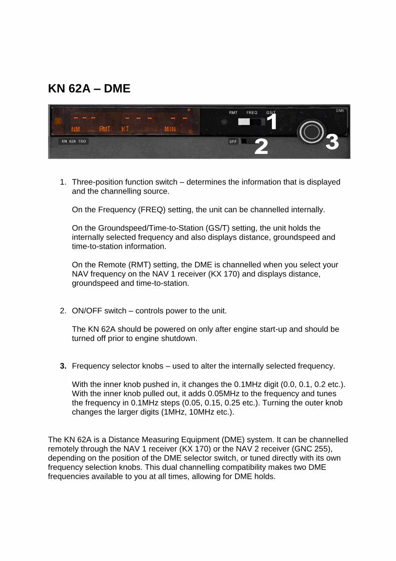
KN 62A – DME
1. Three-position function switch – determines the information that is displayed and the channelling source. On the Frequency (FREQ) setting, the unit can be channelled internally. On the Groundspeed/Time-to-Station (GS/T) setting, the unit holds the internally selected frequency and also displays distance, groundspeed and time-to-station information. On the Remote (RMT) setting, the DME is channelled when you select your NAV frequency on the NAV 1 receiver (KX 170) and displays distance, groundspeed and time-to-station.
2. ON/OFF switch – controls power to the unit. The KN 62A should be powered on only after engine start-up and should be turned off prior to engine shutdown.
3. Frequency selector knobs – used to alter the internally selected frequency. With the inner knob pushed in, it changes the 0.1MHz digit (0.0, 0.1, 0.2 etc.). With the inner knob pulled out, it adds 0.05MHz to the frequency and tunes the frequency in 0.1MHz steps (0.05, 0.15, 0.25 etc.). Turning the outer knob changes the larger digits (1MHz, 10MHz etc.).
The KN 62A is a Distance Measuring Equipment (DME) system. It can be channelled remotely through the NAV 1 receiver (KX 170) or the NAV 2 receiver (GNC 255), depending on the position of the DME selector switch, or tuned directly with its own frequency selection knobs. This dual channelling compatibility makes two DME frequencies available to you at all times, allowing for DME holds.

Frequency mode
In this mode the DME displays distance and the internally selected frequency. You can alter the frequency using the frequency knobs.
Groundspeed/Time-to-Station mode
In this position the DME holds the internally selected frequency while displaying distance, groundspeed and time-to-station. A ‘frequency hold’ feature prevents you from accidentally altering the frequency when it isn’t displayed.
Remote mode
With remote mode selected, the DME uses the frequency that is selected on the
NAV 1 receiver (KX 170) or the NAV 2 receiver (GNC 255), depending on the
position of the DME selector switch. Distance, groundspeed and time-to-station is
shown. Dashes will be displayed when there is no valid signal.

KR 85 – ADF
1. Power/mode selector knob – selects ADF, ANT or BFO mode.
2. Volume knob
3. Frequency display
4. Frequency select knobs – tune the ADF frequency.
Frequency selection The ADF frequency is displayed on three counters. The frequency is selected using the frequency select knobs which are rotated either clockwise or anti-clockwise. The right inner knob tunes the 1s. The right outer knob tunes the 10s. The left knob tunes the 100s and the 1,000s.
Operating modes ANT mode provides improved audio reception from the station tuned and is usually used for identification. The bearing pointer on the ADF indicator will be deactivated and immediately turn to the 90° relative position and remain there during ANT reception. ADF mode activates the bearing pointer on the ADF indicator, causing it to point in the direction of the station relative to the aircraft heading. BFO mode permits the carrier wave and the associated Morse code identifier broadcast on the carrier wave to be heard.
ADF test Select ANT mode and confirm that the bearing pointer moves directly to the parked
90° position. Make sure that the unit is tuned to a usable frequency and then select
ADF mode. Confirm that the needle moves to the station bearing.
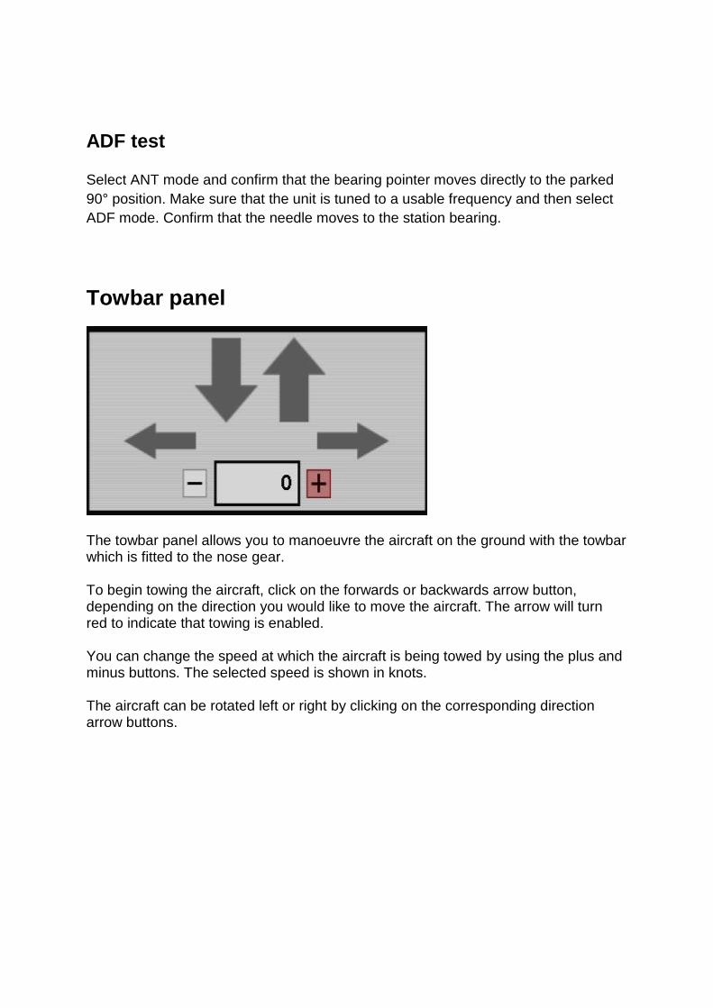
Towbar panel
The towbar panel allows you to manoeuvre the aircraft on the ground with the towbar which is fitted to the nose gear. To begin towing the aircraft, click on the forwards or backwards arrow button, depending on the direction you would like to move the aircraft. The arrow will turn red to indicate that towing is enabled. You can change the speed at which the aircraft is being towed by using the plus and minus buttons. The selected speed is shown in knots. The aircraft can be rotated left or right by clicking on the corresponding direction arrow buttons.

Flight computer

The flight computer provides a variety of information:
Outside air temperature (OAT) – Celsius and Fahrenheit
Groundspeed (GS) – nautical miles per hour, statute miles per hour and kilometres per hour
Endurance – hours and minutes
Range – nautical miles, statute miles, kilometres
Nautical miles per gallon and statute miles per gallon
Density altitude and pressure altitude (feet)
True airspeed (knots), track (degrees) and drift (degrees)
Fuel flow – gallons and litres
Fuel used – total fuel burn (gallons)
Crosswind component (knots)
Headwind/tailwind component (knots) The total fuel burn can be reset by clicking on the RESET FUEL BURN button.
Logbook
The Arrow III comes equipped with a logbook for recording and tracking the hours flown in the aircraft. To make an entry, click on the area into which you wish to type and hold down the [Tab] key. Any subsequent keypresses will be accepted by your flight simulator and entered into the log. Release the [Tab] key when you have finished typing. To remove an entry, or to correct a mistake, press the [Delete] or [Backspace] key (whilst holding the [Tab] key). Entries to the logbook will only be saved when you change page or press the SAVE button in the bottom right corner of the logbook.

The logbook has 50 pages available. To flip through the pages, click on the arrows to either side of the PAGE text in the bottom left corner of the logbook. The PAGE TOTAL count will be updated whenever data is entered into the FLIGHT TIME field. The LOG TOTAL value, which keeps a record of the flight time across all pages in the log, will only be updated when you click SAVE or change pages.
AUTOPILOT
1. Autopilot engage switch
2. Roll command knob
3. Heading switch
4. Navigation/approach coupler knob – middle-button-click on the switch to
toggle altitude hold mode. The tooltip text indicates whether altitude hold
mode is engaged.
5. Coupler radio selector switch – middle-button-click on the switch to control the
NAV/GPS toggle function. The tooltip text indicates whether NAV or GPS
mode is selected.
By modern standards the AutoControl III B is quite a primitive autopilot. It controls
the roll axis of the aircraft but is not equipped to control the pitch axis.
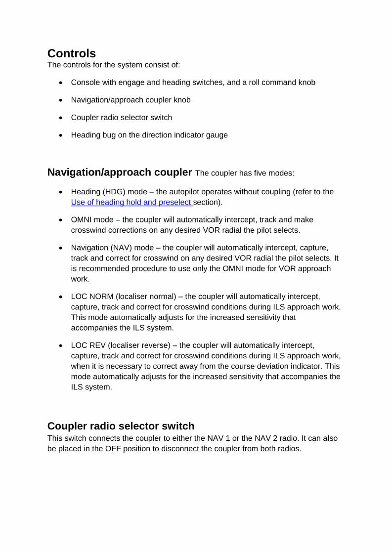
Controls The controls for the system consist of:
Console with engage and heading switches, and a roll command knob
Navigation/approach coupler knob
Coupler radio selector switch
Heading bug on the direction indicator gauge
Navigation/approach coupler The coupler has five modes:
Heading (HDG) mode – the autopilot operates without coupling (refer to the
Use of heading hold and preselect section).
OMNI mode – the coupler will automatically intercept, track and make
crosswind corrections on any desired VOR radial the pilot selects.
Navigation (NAV) mode – the coupler will automatically intercept, capture,
track and correct for crosswind on any desired VOR radial the pilot selects. It
is recommended procedure to use only the OMNI mode for VOR approach
work.
LOC NORM (localiser normal) – the coupler will automatically intercept,
capture, track and correct for crosswind conditions during ILS approach work.
This mode automatically adjusts for the increased sensitivity that
accompanies the ILS system.
LOC REV (localiser reverse) – the coupler will automatically intercept,
capture, track and correct for crosswind conditions during ILS approach work,
when it is necessary to correct away from the course deviation indicator. This
mode automatically adjusts for the increased sensitivity that accompanies the
ILS system.
Coupler radio selector switch This switch connects the coupler to either the NAV 1 or the NAV 2 radio. It can also
be placed in the OFF position to disconnect the coupler from both radios.

Heading bug When the autopilot is engaged, the heading bug becomes the primary control of the
aircraft around the roll axis. When the heading of the aircraft matches the heading
bug, the autopilot will maintain the heading. To turn to a new heading, rotate the
heading bug to the desired heading and the aircraft will turn to the newly selected
heading.
Operation
Pre-flight ground check To ground check the autopilot:
1. Move heading switch to OFF. 2. Centre roll command knob. 3. Engage ON/OFF switch. 4. Rotate the bank command knob right and left – observe that the yoke moves
in the same direction. 5. Return the bank command knob to the centre position.
Preselect 1. Set the heading bug to align with the current heading. 2. Rotate the coupler knob to the heading (HDG) position. 3. Engage the heading switch. 4. Rotate the heading bug to the right – observe that the yoke moves right. 5. Rotate the heading bug to the left – observe that the yoke moves left. 6. Centre the heading bug until the yoke ceases to turn to either side.

Coupler 1. Tune in an available VOR station on the NAV 1 radio. 2. Centre the VOR 1 CDI needle with a ‘TO’ flag using the OBS knob. 3. Set the heading bug to match the selected OBS value. 4. Place the coupler selector switch in the NAV 1 position. 5. Rotate the coupler knob to the OMNI position. 6. Rotate the OBS knob to swing the CDI needle to full right deflection – observe
that the yoke moves right. 7. Rotate the OBS knob to swing the CDI needle to full left deflection – observe
that the yoke moves left. 8. Disengage the autopilot – this completes the ground check.
Engaging in flight Before engaging the autopilot, make certain the aircraft is trimmed for hands-off level flight with the slip-ball centred.
Use of heading hold and preselect 1. Rotate the coupler knob to the heading (HDG) position. 2. Set the heading bug to align with the current heading. 3. Engage the ON/OFF switch. 4. Centre the bank command knob. 5. Engage heading switch.
Heading changes are now made by setting the heading bug to the desired heading. With the heading switch engaged, the roll command knob is inoperative.
Use of roll command function To employ this function the heading switch must be OFF. Bank angles of approximately 30 degrees can be achieved with the roll command knob in the maximum left or right position.
Override Applying a large control input will override the autopilot when engaged. The override should be checked prior to each flight:
1. Rotate the coupler knob to the heading (HDG) position. 2. While the heading bug is set for a left turn, apply a large right input to the
yoke. 3. While the heading bug is set for a right turn, apply a large left input to the
yoke.

Operation of coupler
Intercepting VOR radials 1. While flying with the autopilot engaged and operating in the heading (HDG)
mode, tune in a VOR and set the OBS to the desired radial.
2. Rotate the heading bug to align with the selected OBS.
3. Rotate the coupler from heading (HDG) mode to either navigation (NAV) or
OMNI mode.
4. The aircraft will turn to intercept the desired radial at an angle not exceeding
45°.
5. The coupler will roll the aircraft onto the selected radial and will establish a
crosswind corrected heading.
Note: When flying with a crosswind, the heading bug will not align with the course
flown by the autopilot. The difference between the two is the wind correction (crab)
angle.
VOR navigation 1. The aircraft is inbound and coupled to the 045° radial to VOR ‘A’.
2. When flying over VOR ‘A’, the autopilot will bank the aircraft left and right to
indicate passage over the station. At this point, select the desired outbound
radial (140° in this example) using the OBS knob and align the heading bug to
the same course.
3. The autopilot will bank the aircraft left to intercept the 140° radial of VOR ‘A’,
compensating for any crosswind.
4. As the aircraft moves out of range of VOR ‘A’, tune VOR ‘B’ into the KX-175B
(NAV 2) radio and rotate the OBS knob to select the desired inbound radial.
5. Move the coupler radio selector switch to the NAV 2 position.
6. The autopilot will continue to bank the aircraft to maintain the radial to VOR
‘B’.
7. This procedure is repeated, as described, from VOR to VOR as the aircraft
progresses along its route.
Note: If you wish to use the same VOR receiver for navigating to VOR ‘B’, the
coupler should be placed in heading (HDG) mode while VOR ‘B’ is tuned in.

VOR approach
1. The aircraft is inbound on the 032° radial with compass, direction indictor, heading bug and OBS reading 212°. The coupler is tracking the radial with navigation (NAV) mode selected.
2. When passing overhead the VOR, select the 140° radial in the OBS, set the heading bug to 140° and rotate the coupler mode selector to the OMNI position.
3. The coupler will automatically intercept the 140° radial outbound.
4. When reaching the time for the procedure turn, select the heading (HDG) mode on the coupler and rotate the heading bug to the left to agree with the published outbound heading of the procedure turn (095°).
Note: You must compensate for winds while in HDG mode.
5. At the end of the first leg of the procedure turn, rotate the heading bug to the
right to the reciprocal heading (275°).
6. It is recommended that the OBS be set to the inbound course (320°) while flying the outbound leg of the procedure turn.
7. With the aircraft turning right, set the heading bug further right to the inbound radial of 320° to match the OBS. Rotate the coupler mode selector to the OMNI position.
8. The coupler will now intercept the 140° radial inbound.

ILS approach
1. When receiving vectors to the localiser, set the coupler to heading (HDG) mode and use the heading bug to maintain the provided headings.
2. When the aircraft is in a position for the localiser intercept, select the inbound heading of the localiser using the heading bug before rotating the coupler mode selector to the LOC NORM position.
3. The coupler will intercept the localiser and correct for crosswinds.
4. It is important to note that the coupler only controls the heading of the aircraft and cannot adjust the rate of descent for the glideslope. You must make pitch changes to maintain the glideslope.
5. When passing over the middle marker, disengage the autopilot and take over control of the aircraft. Select heading (HDG) mode on the coupler in case of a go-around.
Note: The heading bug must be set to the inbound heading of the localiser.
ILS back course approach
1. When receiving vectors to the back course of the localiser, set the coupler to heading (HDG) mode and use the heading bug to maintain the provided headings.
2. Set the inbound heading of the back course using the heading bug and switch to LOC REV mode on the coupler.
3. The coupler will intercept the back course and track inbound on the localiser, correcting for crosswinds.

Checklist
Engaging roll command All switches OFF Direction indicator and compass ALIGNED Coupler HDG Engage switch ON Roll command knob Rotate left/right for up to 30° bank
Engaging heading preselect Heading bug Aligned with current heading Heading switch ENGAGED Heading bug Rotate to select heading
Engaging radio coupling NAV 1 / NAV 2 Valid VOR tuned in Coupler radio selector switch NAV 1 or NAV 2 Roll command knob CENTRED Heading switch DISENGAGED OBS Centre CDI needle Heading bug Rotate to selected OBS Coupler NAV Heading switch ENGAGED

GROUND EQUIPMENT The aircraft can be fitted with chocks and tie-downs whilst on the ground.
The chocks and tie-downs will appear whenever the aircraft is on the ground with the engine off, electrical power off and the parking brake applied.

REFILL MENU To simulate the operation of the real aircraft, the engine oil and aircraft battery voltage are recorded whenever you stop flying the Arrow and these quantities will then be restored when the aircraft is next loaded. The engine oil and fuel can be refilled, and the aircraft battery recharged, from the Refill Menu. This menu can be accessed whilst the aircraft is parked with the engine off by moving the ELT switch, located on the left sidewall, to the ON (up) position. It can also be accessed from the menu bar. The engine inspection door will open and the Refill Menu will appear on screen:
Selecting the 'Refill fuel' option will bring up the Fuel Menu, allowing you to set the fuel level from empty (0%) to full (100%):
The Refill Menu also allows you to check the current oil quantity. To close the Refill Menu, select the ‘Close menu’ option or move the ELT switch to AUTO/ARM or OFF/RESET.

FAILURES In addition to supporting the simulator’s own failures system, this Arrow simulation includes a few of the more common failures found on these aircraft:
Spark plug fouling – this can occur if the engine is kept at low RPM for prolonged periods and symptoms include rough running with a subsequent increase in cockpit vibration. If fouling occurs, increase engine RPM.
Vapour lock – this can occur for up to approximately 30 minutes after the engine has been shut down. After shutdown, fuel vapour can remain within the fuel lines as the result of high temperatures. This vapour disrupts the operation of the fuel system and creates an incompatible mix of air and fuel, so you might need a few attempts at starting the engine before ignition occurs. This problem is more likely to occur when operating in high temperatures.
Engine failure caused by low oil quantity – over time the engine will consume oil. The current oil quantity can be checked and refilled using the Refill Menu. If the engine consumes all the oil, the engine will eventually fail.
Battery failure – the battery can be quickly drained either by leaving electrical systems switched on without the engine (and therefore alternator) running, or by repeated attempts to start the engine. The battery can be recharged using the Refill Menu.
These failures are disabled by default and can be enabled/disabled from the menu bar. On-screen messages will appear to warn you in the event of low oil quantity or battery voltage. If you are unable to start the engine, please check the following items: Fuel flow – to ensure sufficient fuel flow for ignition, confirm that the fuel pump is switched on and the mixture lever is set to rich (forward). Confirm fuel flow using the flow gauge prior to attempting an engine start. Refer to the NORMAL PROCEDURES section in the manual for more information. Vapour lock – this can occur for up to approximately 30 minutes after the engine has been shut down. After shutdown, fuel vapour can remain within the fuel lines as the result of high temperatures. This vapour disrupts the operation of the fuel system and creates an incompatible mix of air and fuel, so you might need a few attempts at starting the engine before ignition occurs.
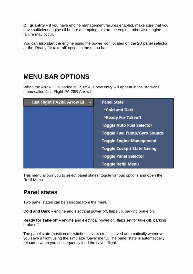
Oil quantity – if you have engine management/failures enabled, make sure that you have sufficient engine oil before attempting to start the engine, otherwise engine failure may occur. You can also start the engine using the power icon located on the 2D panel selector or the 'Ready for take-off' option in the menu bar.
MENU BAR OPTIONS When the Arrow III is loaded in FSX:SE a new entry will appear in the ‘Add-ons’ menu called Just Flight PA-28R Arrow III.
This menu allows you to select panel states, toggle various options and open the Refill Menu. Panel states Two panel states can be selected from the menu: Cold and Dark – engine and electrical power off, flaps up, parking brake on. Ready for Take-off – engine and electrical power on, flaps set for take-off, parking brake off. The panel state (position of switches, levers etc.) is saved automatically whenever you save a flight using the simulator ‘Save’ menu. The panel state is automatically reloaded when you subsequently load the saved flight.

The panel state can also be saved/reloaded automatically between non-saved flights, allowing you to always return to your cockpit in the same state that you last left it. Cockpit state saving can be enabled/disabled using the ‘Toggle Cockpit State Saving’ option. A message will appear on screen to indicate whether the automatic fuel selector is on or off.
Automatic fuel selector The Arrow III is capable of long range flight so we have included an automatic fuel selector switcher, allowing you to leave the PC for prolonged periods without risking a fuel imbalance. This system will automatically switch selected fuel tanks every twenty minutes or if the fuel imbalance is greater than 10 gallons. The automatic fuel selector can be enabled/disabled using the ‘Toggle Auto Fuel Selector’ option. A message will appear on screen to indicate whether the automatic fuel selector is on or off.
Fuel pump / gyro sounds The fuel pump and turn coordinator gyro sounds were recorded from the real aircraft, but we have included an option to disable these sounds if you wish. To toggle these sounds on/off, select ‘Toggle Fuel Pump/Gyro Sounds’. A notification will appear on screen to indicate whether they are on or off.
Engine management You can enable or disable the following engine failure/management features:
Spark plug fouling
Vapour lock
Oil usage and engine failure caused by low oil quantity
Battery usage To enable or disable these features, select the ‘Toggle Engine Management’ option. A notification will appear on screen to indicate whether they are on or off.
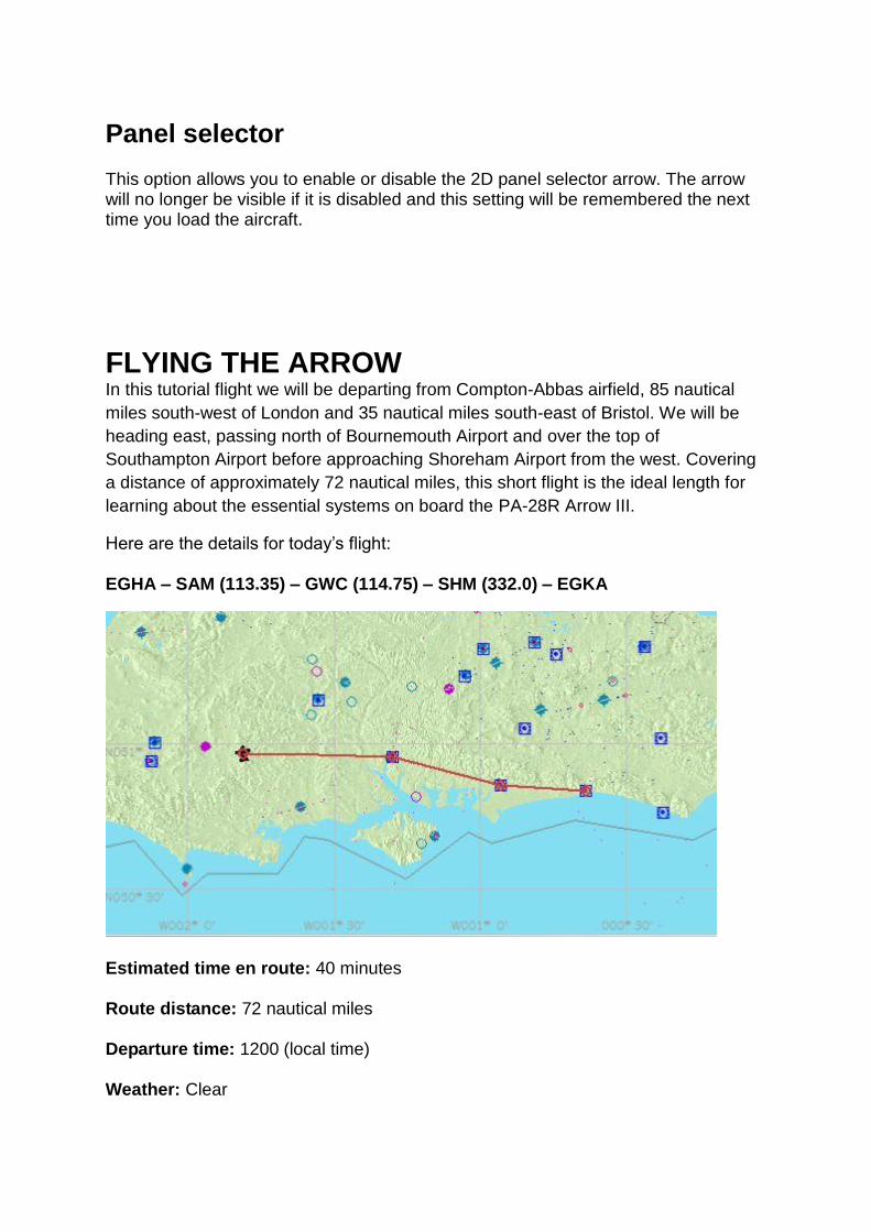
Panel selector This option allows you to enable or disable the 2D panel selector arrow. The arrow will no longer be visible if it is disabled and this setting will be remembered the next time you load the aircraft.
FLYING THE ARROW In this tutorial flight we will be departing from Compton-Abbas airfield, 85 nautical
miles south-west of London and 35 nautical miles south-east of Bristol. We will be
heading east, passing north of Bournemouth Airport and over the top of
Southampton Airport before approaching Shoreham Airport from the west. Covering
a distance of approximately 72 nautical miles, this short flight is the ideal length for
learning about the essential systems on board the PA-28R Arrow III.
Here are the details for today’s flight: EGHA – SAM (113.35) – GWC (114.75) – SHM (332.0) – EGKA
Estimated time en route: 40 minutes Route distance: 72 nautical miles Departure time: 1200 (local time) Weather: Clear

Now that we are prepared for the flight we can proceed to the cockpit to begin our pre-flight checks. To load up the PA-28R Arrow III tutorial flight, follow these steps: 1. Start FSX: Steam Edition.
2. Select the Free Flight menu.
3. Choose Load.
4. Select Just Flight PA-28R Arrow tutorial flight from the list of saved flights.
5. Click on Fly Now!
You should now find yourself sitting in the cockpit at Compton-Abbas airfield. Before we continue, we need to configure the aircraft in a ‘cold and dark’ state, with all the cockpit systems switched off, as you would find the aircraft prior to the first flight of the day. By beginning in this configuration we will need to spend some additional time setting up the cockpit, but doing so will allow you to learn a considerable amount about the features and functions on board this light aircraft. To configure the aircraft in a cold and dark state, open the 2D panel selector and then click on the ‘Toggle Power’ icon (the lightning bolt). The engine will shut down and the electrical power will be switched off.
This tutorial will cover the necessary steps for you to get from point A to point B, but it will not explore each system in depth. Please refer to the rest of this manual for details of each system.

Getting started The first step is to open the door to allow entry into the cockpit. In the virtual cockpit, click on the upper and lower door latches to rotate them to the OPEN position and then click on the door to push it open.
Switch to the exterior (spot) view and then press [Shift]+[E]+[2]. Confirm that the baggage door has opened and then return to the cockpit.
We can now start working through the pre-flight inspections.

To enable easier access to the controls, you may want to hide the yoke using the clickspot at the base of the yoke, where it is mounted to the panel.
Check that the magneto selector is set to OFF (rotated fully anti-clockwise).

Confirm that the landing gear lever is in the DOWN position and that the parking brake handle is set ON.

Check that all avionics are OFF and the mixture lever is set to IDLE CUT-OFF and then switch ON the battery master.
Check the left and right fuel quantity gauges to confirm that we have full tanks (36 gallons per tank).
Confirm that the three green landing gear lights are illuminated.

Switch ON the navigation, rotating beacon, anti-collision and landing lights.
Switch to the exterior (spot) view and confirm that all of the lights are illuminated before returning to the cockpit and switching them all OFF.
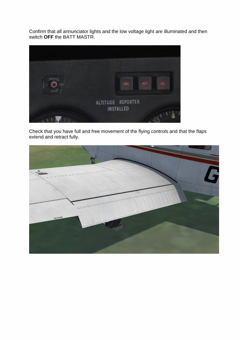
Confirm that all annunciator lights and the low voltage light are illuminated and then switch OFF the BATT MASTR.
Check that you have full and free movement of the flying controls and that the flaps extend and retract fully.

Move the elevator and rudder trims to the centre/neutral position.

Switch to the external (spot) view and carry out a visual inspection of the aircraft. The wheel chocks and tie-downs should be visible. Confirm that the towbar is not connected/visible.
Returning to the cockpit, left-click on the ELT switch located on the left sidewall to move it to the ON position.

The ‘Refill Menu’ window will appear. This menu allows you to refill the engine oil and fuel, recharge the aircraft battery and check the oil quantity.
Use the menu to recharge the battery in case it has discharged while you’ve been finding your way around the cockpit, and then check the oil quantity, which will be displayed in the top left corner of the screen. If the oil quantity displayed is less than 8 quarts, use the ‘Refill Oil’ option to top up the engine oil.
We are now finished with the Refill Menu, so select the ‘Close menu’ option. Once the menu has closed, right-click on the ELT switch to move it back to the AUTO/ARM position.

Starting the engine To avoid battery draining we will start the engine before configuring the avionics for our departure. Close the baggage door by pressing [Shift]+[E]+[2] and then close the passenger door by first clicking on the door to pull it shut and then clicking on the door latches to rotate them to the LATCH position.

Check that the parking brake is set and that all circuit breakers are pushed in.
On the left sidewall, right-click on the fuel selector to rotate it to the LEFT position.

On the throttle quadrant, move the propellor lever to the FULL FORWARD position and advance the throttle lever to approximately 1/4 open.

Confirm that the alternate air is set to CLOSE and that all avionics are still OFF.
Switch ON the battery master to provide electrical power to the aircraft.
Turn ON the navigation and rotating beacon lights, warning anyone in the area that we are about to start the engine.

Switch ON the fuel pump and then move the mixture lever to the FULL RICH (forward) position until fuel flow is displayed.
Check that the area surrounding the aircraft is clear of obstructions and then rotate the magneto/start selector to the START (fully clockwise) position.

When the engine starts, release the magneto/start selector and it will return to the BOTH position. Check that the oil pressure and temperature are rising.
Switch ON the ALT (alternator) switch breaker and confirm that the associated warning light on the annunciator panel extinguishes.
Adjust the throttle to maintain 1,400-1,500 RPM and check that the vacuum gauge shows suction within the given limits.

With the engine running and the alternator charging the battery, we can now switch on the avionics. Starting at the top of the centre panel and working down, switch on the KX 170B, KX 175B, KT 76A, GPS 100, KN 62A and KR 85 units. We will leave the autopilot unit switched off for now.
Finally, rotate the fuel selector switch to the RIGHT and then the LEFT position, checking that the engine operates correctly on both tanks before selecting the fullest tank.

Configuring the avionics We now need to configure the avionics for our departure. For the initial climb we are going to maintain the runway heading, so rotate the heading bug on the direction indicator to 080 degrees.
Once we are settled into our climb to the east we will make a turn to fly towards the first waypoint on the route, Southampton (SAM) VOR. In preparation, tune the VOR frequency (113.35) into the KX 170B (NAV 1) unit.

Tune the second waypoint on our route, Goodwood VOR (114.75), into the KX 170B (NAV 2) unit.

Check that the function switch on the KN 62A is set to the RMT (remote) position and that the DME selector switch, located above the GPS 100 unit, is set to NAV 1. Selecting the remote function allows the KN 62A to display DME information from either NAV1 (the KX 170B) or NAV 2 (the KX 175B), rather than its own internal NAV receiver. The DME selector switch controls which of the two radio units the KN 62A receives its DME information from – in this case the KX 170B, which we have just tuned to the Southampton VOR.

Taxi We can now taxi to the runway. Check that the area around the aircraft is clear of obstacles and then release the parking brake. Apply power slowly to get the aircraft rolling and then start your taxi to the threshold of runway 08. Steering the aircraft with the rudder pedals only is generally sufficient. The combined use of the rudder pedals and the brakes permits, if necessary, tight turns. Check the operation of gyroscopic instruments (horizontal attitude, heading and turn and bank indicators) by means of alternate turns. Stop at the holding point just short of runway 08. We can carry out the power (ground) check here. Set the parking brake and confirm that the propeller lever is in the FULL FORWARD position. To carry out a magneto check, advance the throttle lever to obtain 2,000 RPM and then rotate the magneto selector to the LEFT position, note the RPM drop and then rotate it back to the BOTH position. Repeat the process for the right magneto. Check that the vacuum, oil temperature, oil pressure and ammeter readings are within limits.

Use the PRESS-TO-TEST button to confirm that all the annunciator lights illuminate.
Make sure that the mixture lever is set to FULL RICH (fully forward) and the fuel selector is set to the fullest tank.

To carry out a propeller check, advance the throttle lever to obtain 2,000 RPM and then cycle the propeller lever twice, moving it aft towards the high pitch/low RPM position and then forwards towards the low pitch/high RPM position. Note the RPM drop on the tachometer. Reset the lever to the FULL FORWARD position.
To carry out an alternate air check, pull the alternate air knob and check that the manifold pressure doesn’t drop, then push the alternate air knob in again.
Check the operation of the fuel system by switching the fuel pump OFF and confirming that the fuel pressure is still within the green sector. Finally, reduce the throttle to idle and check for rough running. We can now run through the before take-off checks.

Confirm that the battery master and alternator switches are both set to ON. Rotate the fuel selector to the fullest tank and switch ON the fuel pump. Check that the alternate air lever is set to CLOSE, and that the mixture and propeller levers are in the FULL FORWARD position. Lower the flaps to the 10° (first stage) position.
Confirm the magneto selector is in the BOTH position and switch ON the landing and anti-collision lights.

Rotate the pitch trim wheel until the indicator sits in the neutral/centre position.
Confirm that both doors are LOCKED and that you have full and free movement of the flying controls. Finally, switch ON the PITOT HEAT switch. With the before take-off checks complete, have a look left and right, verify that nothing is on approach and that the runway is clear, and then taxi onto the runway.
Take-off Line up with the runway centre line and then come to a stop. Smoothly apply full power, and as the aircraft starts to gather speed, keep it running down the centre line with rudder inputs. As you approach 65 knots start to raise the nose of the aircraft. The aircraft will begin to climb away from the runway and once you are safely airborne, tap the brakes and then raise the landing gear using the [G] key. Make elevator inputs as required to maintain a climb speed of approximately 90 knots, holding the runway heading (080 degrees) and retracting the flaps as you pass through 300ft AGL.

Climb Once stable in the climb, adjust your pitch to maintain the 90 knots climb speed and maintain your heading. Switch OFF the fuel pump and landing light on reaching 1,000 feet. As you climb through 2,000 feet, the Southampton VOR should be within range of the aircraft. The NAV flag on the VOR 1 indicator will disappear to indicate that a valid signal is being received and the KN 62A will display the DME distance (nautical miles), groundspeed (knots) and time-to-station (minutes).

Rotate the OBS knob on the VOR 1 indicator until the CDI needle centres with a TO flag visible – approximately 095 degrees.
Bank the aircraft to the right to bring it onto the OBS course, so that you are tracking inbound to the VOR. To reduce your workload we will now engage the autopilot and command it to maintain the course to the VOR.

Move the autopilot engage switch to the A/P ON position to engage the autopilot, and move the heading switch to the HDG ON position to enable the autopilot to take control of the aircraft’s heading.
Check that the coupler radio selector switch is set to NAV 1. This switch connects the coupler to either the NAV 1 or the NAV 2 radio and, as we’ve tuned the Southampton VOR into the NAV radio, we need to couple the autopilot to that same radio.

Finally, make sure that the navigation/approach coupler knob is set to NAV. This selects navigation hold mode.
The autopilot will now control the heading and maintain our course to the VOR. Note that the autopilot is not controlling the aircraft’s pitch, so continue to adjust your pitch to maintain the climb.
Cruise As you approach 4,000ft, place your mouse cursor over the navigation/approach coupler knob and press the middle button on your mouse (this is often integrated into the mouse-wheel). Alternatively, you can use the default key assignment – [Ctrl]+[Z]. This toggles altitude hold mode. The autopilot will capture and hold the current altitude (rounded to the nearest hundred feet). A tooltip indicates whether altitude hold mode is engaged.
The real-life Piper AutoControl IIIB doesn’t feature altitude hold mode but it has been included for convenience.

As the aircraft levels out and begins to accelerate, reduce the throttle to obtain 23 IN.HG. on the manifold pressure gauge and then reduce the propeller lever to obtain 2,200 RPM on the tachometer. This is a typical cruise power setting.
It is important to remember that the engine is only being fed with fuel from a single tank at any given time, and therefore the quantity of each tank should be carefully monitored. It is recommended that you change fuel tanks every half hour and do not exceed a fuel imbalance of 10 US gallons. If you want to avoid worrying about switching fuel tanks, enable the automatic fuel selector from the ‘Add-Ons’ menu. You can now relax for a while as the autopilot takes care of controlling the aircraft. The leg to the Southampton VOR should take approximately 10 minutes, as displayed on the KN 62A. This is the ideal opportunity to take a closer look at some of the features of the aircraft. The Arrow III has a very capable IFR-capable avionics fit. We’ll take a quick look at some of the features of those avionics. Make sure you keep an eye on the distance remaining to the Southampton VOR, as we’ll need to return to navigating the aircraft once we are five miles from the VOR. Sliding over to the KN 62A unit, move the function switch to the FREQ (frequency) position. With this function selected we can tune the KN 62A’s internal receiver (NAV 3). Rotate the frequency selector knobs to tune in 114.35, the frequency for the Compton VOR/DME which is commonly used by airliners transiting the London airspace. The DME distance (nautical miles) to the VOR will be shown on the left of the display. Move the function switch to the GS/T (groundspeed/time) position to show the DME distance (nautical miles), groundspeed (knots) and time-to-station (minutes) to the London VOR. Note that the display is identical to that shown with RMT (remote) selected, but this display shows the information for the internally tuned frequency rather than the remote frequency (NAV 1 – KX 170 or NAV 2 – KX 175).
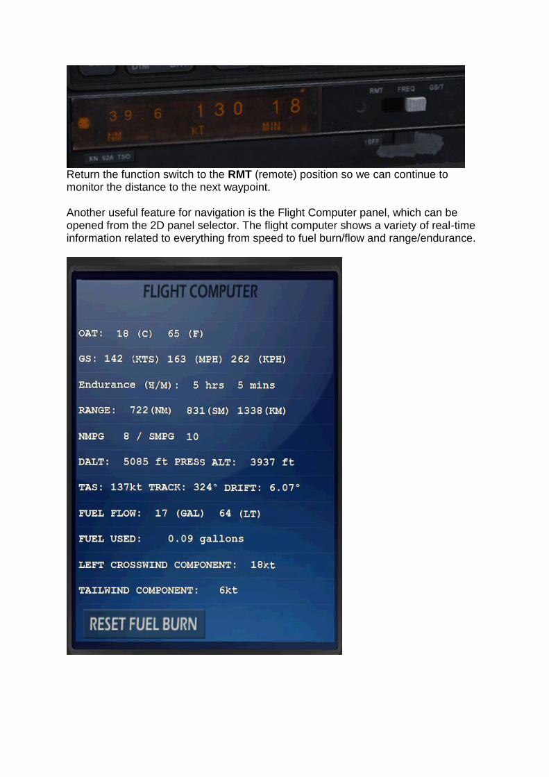
Return the function switch to the RMT (remote) position so we can continue to monitor the distance to the next waypoint. Another useful feature for navigation is the Flight Computer panel, which can be opened from the 2D panel selector. The flight computer shows a variety of real-time information related to everything from speed to fuel burn/flow and range/endurance.

With five miles to run to the Southampton VOR, rotate the OBS knob on the VOR 2 indicator until the CDI needle centres with a TO flag visible – approximately 105 degrees – and then move the coupler radio selector switch to NAV 2.
The autopilot will now bank the aircraft to maintain the selected course to the VOR tuned into the KX 175 (NAV 2) – Goodwood VOR.

Set the DME selector switch to NAV 2 so that we can monitor the distance to the Goodwood VOR on the KN 62.
We can now tune in the Shoreham (SHM) NDB, which is situated on the airfield. Using the selector knobs on the KR 85, tune in 0332 (332 kHz) and make sure that the mode knob is set to ADF.

The needle on the ADF indicator will point towards the Shoreham NDB when it comes within range (approximately 20 miles out from the Goodwood VOR), which should be ahead of the aircraft and on a similar heading to the VOR which is located close by.
When the KN 62 shows that we are three miles from the Goodwood VOR, rotate the heading bug on the direction indicator to match up with your current heading and then rotate the navigation/approach coupler knob to the HDG position. The autopilot will now maintain our current heading.

Now use the heading bug to track towards the NDB, using the ADF indicator to estimate what heading is required for a direct routing to the NDB.

Descent We need to begin our descent when we are approximately seven miles past the Goodwood VOR. The distance from the VOR is still available on the KN 62 although we are now using the ADF indicator for nagivation. Move the propeller lever forwards to the fully forward (high RPM) position and then reduce the throttle to obtain 15 inHG on the manifold pressure gauge. The airspeed will start to decrease.
Once the airspeed has reduced to 110 knots, start the descent by disengaging altitude hold mode and then pitching down to obtain a -500ft/min descent rate. As the aircraft stabilises in its descent, adjust the throttle to maintain 110 knots.

Approach and landing As Shoreham Airport comes into view, position the aircraft to join the base leg for runway 02, using the heading bug to turn the aircraft right, towards the coastline. Continue to follow the coastline east towards the airport.
As you approach 1,000ft, reduce your vertical speed to enter level flight and increase the throttle as the aircraft levels out to maintain your airspeed. Disengage the autopilot by moving the heading switch to HDG OFF and the engage switch to A/P OFF.

Switch ON the landing light and fuel pump.
Confirm that the propeller and mixture levers are fully forward and that the fuel selector is set to the fullest tank. Once established on the base leg for runway 02, reduce your airspeed to 100 knots and extend the flaps to the 10° position.
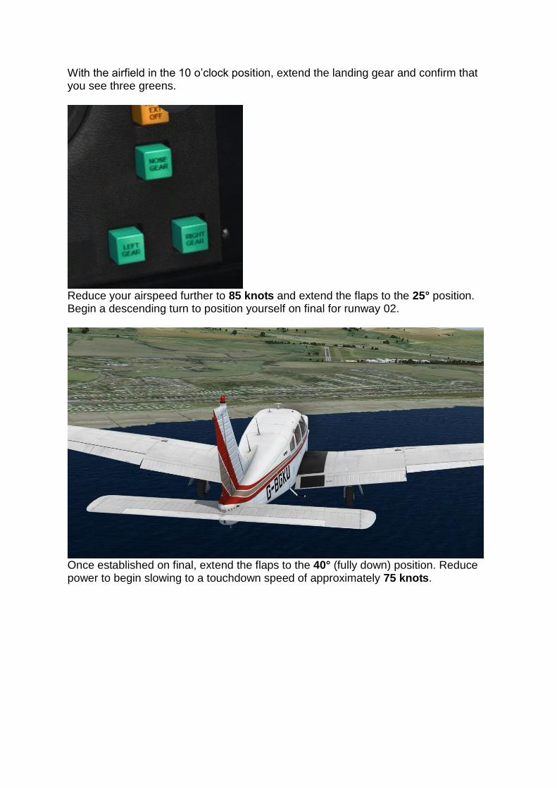
With the airfield in the 10 o’clock position, extend the landing gear and confirm that you see three greens.
Reduce your airspeed further to 85 knots and extend the flaps to the 25° position. Begin a descending turn to position yourself on final for runway 02.
Once established on final, extend the flaps to the 40° (fully down) position. Reduce power to begin slowing to a touchdown speed of approximately 75 knots.

As the aircraft arrives over the runway, start to bring the aircraft into a flare, gently raising the nose just above the horizon. Reduce the throttles to idle and the aircraft should touch down smoothly.
Apply gentle braking and once the aircraft has slowed to a fast walking pace, turn right off the runway. When you are safely off the runway, raise the flaps and switch OFF the landing and anti-collision lights. You can also switch OFF the fuel pump and pitot heat.
Shutdown Begin your taxi to the nearest available parking spot. Once you have come to a stop at your chosen parking spot, engage the parking brake and switch OFF the avionics. Bring the throttle lever back to IDLE and then bring the mixture lever back to IDLE CUT-OFF to shut down the engine (remember to disengage the mixture lock!). Once the engine comes to a stop, rotate the magneto selector to the OFF position. Switch OFF the navigation and rotating beacon lights, and then switch OFF the alternator and battery to disconnect the electrical power. Rotate the fuel selector to the FUEL OFF position and and open the passenger and baggage doors. Congratulations – you have completed the Arrow III tutorial flight!

NORMAL PROCEDURES
Airspeed (IAS) for safe operations Best rate of climb (gear up, flaps up) 90 KIAS Best rate of climb (gear down, flaps up) 78 KIAS Best angle of climb (gear up, flaps up) 78 KIAS Best angle of climb (gear down, flaps up) 72 KIAS Operating speed in turbulent air 118 KIAS Maximum flap speed 103 KIAS Final approach speed (flaps 40) 75 KIAS Maximum demonstrated crosswind 17 KIAS

Pre-flight
Cockpit Landing gear lever DOWN Parking brake SET Avionics OFF Mixture IDLE CUT-OFF Magneto switch OFF BATT MASTR switch ON Fuel gauges CHECK QUANTITY Annunciator panel CHECK BATT MASTR switch OFF Primary flight controls CHECK OPERATION Flaps CHECK OPERATION Trim NEUTRAL Baggage door CLOSED
Left/right wing Flap and aileron CHECK Wing tip and lights UNDAMAGED Tie-down REMOVED Fuel tank CHECK LEVEL
Nose section Chocks REMOVED Towbar REMOVED (NOSE GEAR) Engine inspection door CLOSED Oil CHECK LEVEL Propeller GOOD CONDITION Air inlets CLEAR Landing light CHECK
Tail section Fin CHECK CONDITION Rudder CHECK CONTROLS Stabilator and trim tab CHECK CONTROLS Tail cone CHECK CONDITION

Before starting engine Brakes SET Circuit breakers IN Alternate air OFF Propeller FULL FORWARD Avionics OFF Fuel selector DESIRED TANK
Engine starting Caution: If a positive oil pressure is not indicated within 30 seconds after an engine start, stop the engine and determine the trouble. In cold weather it will take a few seconds longer to get a positive oil pressure indication.
Cold engine Throttle ½ INCH OPEN ALTR switch ON BATT MASTR switch ON Fuel pump ON Mixture RICH then IDLE CUT-OFF Propeller CLEAR Starter ENGAGE Mixture FULL RICH When the engine starts: Magneto selector BOTH Throttle ADJUST Oil pressure CHECK Throttle 1,400-1,500 RPM

Hot engine Throttle ½ INCH OPEN ALTR switch ON BATT MASTR switch ON Fuel pump ON Mixture IDLE CUT-OFF Propeller CLEAR Starter ENGAGE Mixture ADVANCE When the engine starts: Magneto selector BOTH Throttle ADJUST Oil pressure CHECK Throttle 1,400-1,500 RPM
Taxiing Taxi area CLEAR Parking brake RELEASE Throttle APPLY SLOWLY Brakes CHECK Steering CHECK Steering the aircraft with the rudder pedals only is generally sufficient. The combined use of the rudder pedals and the brakes permits, if necessary, tight turns. Check the operation of gyroscopic instruments (horizontal attitude, heading and turn and bank indicators) by means of alternate turns.
Ground check Parking brake SET Propeller FULL FORWARD Throttle 2,000 RPM Magnetos CHECK (max. drop 175 RPM) Vacuum 4.8-5.1 inHG Oil temperature CHECK Oil pressure CHECK

Ammeter CHECK Annunciator panel PRESS-TO-TEST Propeller EXERCISE then FULL FORWARD Alternate air CHECK Fuel pump OFF Fuel pressure CHECK Throttle RETARD
Before take-off BATT MASTR switch ON ALTR switch ON Flight instruments CHECK Fuel selector AS REQUIRED Fuel pump ON Engine checks CHECK Alternate air CLOSED Mixture SET Propeller SET Flaps SET Trim SET Controls FREE Doors LATCHED
Take-off Lined up on runway CHECK COMPASS
Normal technique Flaps SET Trim SET Accelerate to 65-75 KIAS. Yoke Back pressure to rotate smoothly to climb attitude
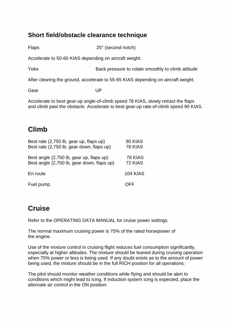
Short field/obstacle clearance technique Flaps 25° (second notch) Accelerate to 50-60 KIAS depending on aircraft weight. Yoke Back pressure to rotate smoothly to climb attitude After clearing the ground, accelerate to 55-65 KIAS depending on aircraft weight. Gear UP Accelerate to best gear-up angle-of-climb speed 78 KIAS, slowly retract the flaps and climb past the obstacle. Accelerate to best gear-up rate-of-climb speed 90 KIAS.
Climb Best rate (2,750 lb, gear up, flaps up) 90 KIAS Best rate (2,750 lb, gear down, flaps up) 78 KIAS Best angle (2,750 lb, gear up, flaps up) 78 KIAS Best angle (2,750 lb, gear down, flaps up) 72 KIAS En route 104 KIAS Fuel pump OFF
Cruise Refer to the OPERATING DATA MANUAL for cruise power settings. The normal maximum cruising power is 75% of the rated horsepower of the engine. Use of the mixture control in cruising flight reduces fuel consumption significantly, especially at higher altitudes. The mixture should be leaned during cruising operation when 75% power or less is being used. If any doubt exists as to the amount of power being used, the mixture should be in the full RICH position for all operations. The pilot should monitor weather conditions while flying and should be alert to conditions which might lead to icing. If induction system icing is expected, place the alternate air control in the ON position.

To keep the aircraft in best lateral trim during cruise flight, fuel should be used alternately from each tank at 15-minute intervals. Always remember that the electric fuel pump should be turned ON before switching tanks and should be left on for a short period thereafter.
Descent Set the required power for descent. Apply engine power every 1,500ft to prevent excess engine cooling and spark plug fouling. Avoid prolonged descents with a manifold pressure lower than 14 inHG.
Approach and landing Fuel selector FULLEST TANK Fuel pump ON Mixture SET Propeller FULL FORWARD Gear DOWN (129 KIAS max.) Flaps SET (103 KIAS max.) Trim to 75 KIAS.
Shutdown Flaps RETRACT Fuel pump OFF Avionics OFF Electrical switches OFF Propeller FULL FORWARD Throttle CLOSED Mixture IDLE CUT-OFF Magnetos OFF ALTR switch OFF BATT MASTR switch OFF

Stalls The stall characteristics of the Arrow are conventional. An approaching stall is indicated by a stall warning horn which is activated between five and ten knots above stall speed. Mild airframe buffeting and gentle pitching may also precede the stall. The gross weight stalling speed of the Arrow with power off and full flaps is 55 KIAS. With the flaps up, this speed is increased by 5 knots. Loss of altitude during stalls can be as great as 400 feet, depending on configuration and power. Note: The stall warning system is inoperative with the battery master switch OFF.
EMERGENCY PROCEDURES
Airspeed (IAS) for safe operations Stall speed (2,750 lb, gear up, flaps 0) 60 KIAS Stall speed (2,750 lb, gear down, flaps 40) 55 KIAS Manoeuvring speed (2,750 lb) 118 KIAS Manoeuvring speed (1,865 lb) 96 KIAS Never exceed speed 183 KIAS Power off glide speed (2,750 lb, gear up, flaps 0) 79 KIAS

Engine failures
Engine failure during start Starter CRANK ENGINE Mixture IDLE CUT-OFF Throttle OPEN Fuel pump OFF Fuel selector OFF
Engine failure during take-off If sufficient runway remains for a normal landing, leave gear down and land straight ahead. If area ahead is rough or if it is necessary to clear obstructions: Landing gear lever UP If sufficient attitude has been gained to attempt a restart: Fuel selector SET TO FULLEST TANK Fuel pump CHECK ON Mixture CHECK RICH Alternate air OPEN If power is not regained, proceed with power off landing.
Engine failure in flight If at low altitude: Airspeed 79 KIAS minimum Prepare for power off landing. If altitude permits: Fuel selector SWITCH TO FULLEST TANK Fuel pump ON

Mixture RICH Alternate air OPEN Engine gauges Check for indication of cause If no fuel flow/pressure is indicated, check tank selector position to be sure it is on a tank containing fuel. When power is restored: Alternate air CLOSE Fuel pump OFF If power is not restored, prepare for power off landing. Trim for 79 KIAS.
Power off landing Trim for 79 KIAS. Locate suitable field and establish spiral pattern 1,000ft above field at downwind position for normal landing approach. When field can be easily reached, slow to 72 KIAS for shortest landing.
Gear down emergency landing Touchdowns should normally be made at the lowest possible airspeed with full flaps. When committed to landing: Landing gear lever AS REQUIRED Flaps AS DESIRED Throttle CLOSE Mixture IDLE CUT-OFF Ignition OFF BATT MASTR switch OFF ALTR switch OFF Fuel selector OFF Note: If battery master switch is OFF, the landing gear cannot be retracted.

Gear up emergency landing If a gear up landing is required, proceed as follows: Flaps AS DESIRED Throttle CLOSE Mixture IDLE CUT-OFF Ignition OFF BATT MASTR switch OFF ALTR switch OFF Fuel selector OFF Contact surface at minimum possible airspeed.
Fires
Engine fire in flight Fuel selector OFF Throttle CLOSED Mixture IDLE CUT-OFF Fuel pump OFF Cabin heat OFF Proceed with power off landing procedure.
Electrical fire BATT MASTR switch OFF ALTR switch OFF Cabin heat OFF Land as soon as possible.

Low oil pressure Oil annunciator light ON Pressure indicator IN LOW SECTOR Throttle REDUCE AS FAR AS POSSIBLE Oil temperature CHECKED If oil temperature in red sector REDUCE THROTTLE Prepare for a forced landing and land as soon as possible.
Low fuel flow/pressure Fuel pump ON Fuel quantity CHECKED Fuel selector SWITCH TANKS
Propeller governor failure In case of oil pressure drop in the governor system or pitch control failure, the propeller moves to low pitch. Oil pressure CHECKED Oil temperature CHECKED Throttle AS REQUIRED Airspeed REDUCED Avoid rapid application of power – maximum RPM is 2,700.
Electrical failures Check the circuit breakers panel. If the circuit breaker is open, close it only once. If it opens again do not try to close the circuit breaker as the equipment has failed. ALT annunciator light illuminated: Ammeter Check to verify inoperative alternator If ammeter shows zero:

ALTR switch OFF Reduce electrical loads to minimum: ALNTR. FIELD circuit breaker Check and reset as required ALTR switch ON If power is not restored: ALTR switch OFF If alternator output cannot be restored, reduce electrical loads and land as soon as practical. The battery is the only remaining source of electrical power.
Icing IMPORTANT! Flight into known icing conditions is prohibited. Alternate air OPEN Cabin heat FULL HOT Pitot heat ON Engine MAX. POWER/RPM Adjust course and/or altitude to obtain best outside air conditions. Divert to nearest airport.
Emergency landing gear extension Prior to emergency extension procedure: BATT MASTR switch ON ALTR switch ON Circuit breakers Check NAV LIGHT switch OFF If landing gear fails to extend: Airspeed Reduce below 87 KIAS Landing gear lever DOWN

If gear has still failed to lock down, move and hold the emergency lever down to the Emergency Down position. If gear has still failed to lock down, yaw the aircraft abruptly from side to side with the rudder.
Spin recovery Intentional spins are prohibited, but if an inadvertent spin does occur, the following recovery procedure is recommended: Rudder HOLD OPPOSITE DIRECTION OF ROTATION Yoke FULL FORWARD, AILERONS NEUTRAL Throttle IDLE When spinning stops, centralise rudder, level the wings and ease out of the dive.
Airspeed indicating system failure In case of erroneous indications in flight: Pitot heat ON If erroneous indications persist, carry out a precautionary approach, maintaining an adequate airspeed margin above stall warning activation speed.
CREDITS Project management Martyn Northall Aircraft modelling and design Mark Griffiths Aircraft systems and cockpit programming Martyn Northall Flight dynamics Paul Frimston Sounds Turbine Sound Studios Manual Martyn Northall Installer Martin Wright Design Fink Creative Special thanks to all the testers

COPYRIGHT ©2017 Just Flight. All rights reserved. Just Flight and the Just Flight logo are trademarks of JustFlight London Limited, St. George’s House, George Street, Huntingdon, PE29 3GH, UK. All trademarks and brand names are trademarks or registered trademarks of the respective owners and their use herein does not imply any association or endorsement by any third party.