Operation & Service Manual - Hipotgo.hipot.com/rs/414-IRJ-976/images/290-Manual.pdf · tester for...
62
Operation & Service Manual Model 294, 295, 296, 297, 298 • V1.05 Model 294 (DC Hipot Tester) Model 295 (AC Hipot Tester) Model 296 (AC/DC Hipot Tester) Model 297 (AC/DC Hipot With IR Tester) Model 298 (500VA AC Hipot Tester) Item 99-10813-01 Printed May 21, 2020 RoHS 2 COMPLIANT 2011/65/EU
Transcript of Operation & Service Manual - Hipotgo.hipot.com/rs/414-IRJ-976/images/290-Manual.pdf · tester for...
Operation & Service Manual
Model 294, 295, 296, 297, 298 • V1.05
Model 294 (DC Hipot Tester)Model 295 (AC Hipot Tester)
Model 296 (AC/DC Hipot Tester)Model 297 (AC/DC Hipot With IR Tester)
Model 298 (500VA AC Hipot Tester)
Item 99-10813-01
Printed May 21, 2020
RoHS 2COMPLIANT2011/65/EU

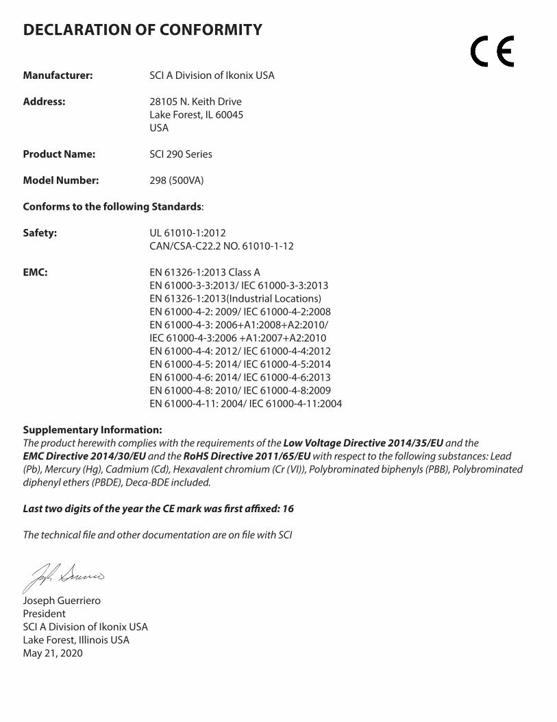
DECLARATION OF CONFORMITY
Manufacturer: SCI A Division of Ikonix USA
Address: 28105 N. Keith Drive Lake Forest, IL 60045 USA
Product Name: SCI 290 Series
Model Number: 294, 295, 296, 297
Conforms to the following Standards:
Safety: UL 61010-1:2012 CAN/CSA-C22.2 NO. 61010-1-12
EMC: EN 61326-1:2013 Class A EN 55011:2009+A1:2010 Group 1, Class A, EN 61000-3-2:2014/IEC 61000-3-2 :2014, EN 61000-3-3:2013/ IEC 61000-3-3 :2013, EN 61326-1 :2013(Industrial Locations) EN 61000-4-2:2009/IEC 61000-4-2 :2008 EN 61000-4-3:2006+A1 :2008+A2 :2010, IEC 61000-4-3:2006+A1 :2007+A2 :2010, EN 61000-4-4:2012/IEC 61000-4-4:2012, EN 61000-4-5:2006 /IEC 61000-4-5 :2005 EN 61000-4-6:2014/IEC 61000-4-6:2013, EN 61000-4-8:2010/IEC 61000-4-8 :2009, EN 61000-4-11 :2004/IEC 61000-4-11 :2004
Supplementary Information:The product herewith complies with the requirements of the Low Voltage Directive 2014/35/EU and the EMC Directive 2014/30/EU and the RoHS Directive 2011/65/EU with respect to the following substances: Lead (Pb), Mercury (Hg), Cadmium (Cd), Hexavalent chromium (Cr (VI)), Polybrominated biphenyls (PBB), Polybrominated diphenyl ethers (PBDE), Deca-BDE included.
Last two digits of the year the CE mark was first affixed: 16
The technical file and other documentation are on file with SCI
Joseph GuerrieroPresidentSCI A Division of Ikonix USALake Forest, Illinois USA May 21, 2020
DECLARATION OF CONFORMITY
Manufacturer: SCI A Division of Ikonix USA
Address: 28105 N. Keith Drive Lake Forest, IL 60045 USA
Product Name: SCI 290 Series
Model Number: 298 (500VA)
Conforms to the following Standards:
Safety: UL 61010-1:2012 CAN/CSA-C22.2 NO. 61010-1-12
EMC: EN 61326-1:2013 Class A EN 61000-3-3:2013/ IEC 61000-3-3:2013 EN 61326-1:2013(Industrial Locations) EN 61000-4-2: 2009/ IEC 61000-4-2:2008 EN 61000-4-3: 2006+A1:2008+A2:2010/ IEC 61000-4-3:2006 +A1:2007+A2:2010 EN 61000-4-4: 2012/ IEC 61000-4-4:2012 EN 61000-4-5: 2014/ IEC 61000-4-5:2014 EN 61000-4-6: 2014/ IEC 61000-4-6:2013 EN 61000-4-8: 2010/ IEC 61000-4-8:2009 EN 61000-4-11: 2004/ IEC 61000-4-11:2004
Supplementary Information:The product herewith complies with the requirements of the Low Voltage Directive 2014/35/EU and the EMC Directive 2014/30/EU and the RoHS Directive 2011/65/EU with respect to the following substances: Lead (Pb), Mercury (Hg), Cadmium (Cd), Hexavalent chromium (Cr (VI)), Polybrominated biphenyls (PBB), Polybrominated diphenyl ethers (PBDE), Deca-BDE included.
Last two digits of the year the CE mark was first affixed: 16
The technical file and other documentation are on file with SCI
Joseph GuerrieroPresidentSCI A Division of Ikonix USALake Forest, Illinois USA May 21, 2020

Warranty Policy
SCI certifies that the tester listed in this manual meets or exceeds published manufacturing specifications. This tester was calibrated using standards that are traceable to the National Institute of Standards and Technology (NIST).
Your new tester is warranted to be free from defects in workmanship and material for a period of (1) year from date of shipment.
SCI recommends that your tester be calibrated on a twelve-month cycle. A return material authorization (RMA) must be obtained from SCI. Please contact our Customer Support Center at 1-847-932-3662 to obtain an RMA number. Damages sustained as a result of improper packaging will not be honored. Transportation costs for the return of the tester for warranty service must be prepaid by the customer. SCI will assume the return freight costs when returning the tester to the customer. The return method will be at the discretion of SCI.
Except as provided herein, SCI makes no warranties to the purchaser of this tester and all other warranties, express or implied (including, without limitation, merchantability or fitness for a particular purpose) are hereby excluded, disclaimed and waived.
Any non-authorized modifications, tampering or physical damage will void your warranty. Elimination of any connections in the earth grounding system or bypassing any safety systems will void this warranty. This warranty does not cover accessories not of SCI manufacture. Parts used must be parts that are recommended by SCI as an acceptable specified part. Use of non-authorized parts in the repair of this tester will void the warranty.

TABLE OF CONTENTS
SAFETY PRECAUTIONS REQUIRED FOR HIGH VOLTAGE TESTING! ........................................................................................6Front Panel Controls ........................................................................................................................................................................7Rear Panel Controls .........................................................................................................................................................................8Setup Instructions .........................................................................................................................................................................11Power-Up Sequence ......................................................................................................................................................................11 Getting To Know Your Tester ..............................................................................................................................................................................................12 1. Working With Memories ..............................................................................................................................................................................................12 2. Perform Test Screen .......................................................................................................................................................................................................12 3. Selecting Memory ..........................................................................................................................................................................................................13 4. Setting an AC Hipot Test ..............................................................................................................................................................................................14 5. Setting a DC Hipot Test ................................................................................................................................................................................................19 6. Setting an IR Test .............................................................................................................................................................................................................23 System Parameter Descriptions ........................................................................................................................................................................................27 Setting System Parameters .................................................................................................................................................................................................28 Using The Display ....................................................................................................................................................................................................................30 1. Test Mode Displays .........................................................................................................................................................................................................30 2. Failure Mode Displays ...................................................................................................................................................................................................30 3. Error Messages .................................................................................................................................................................................................................31 Reviewing Test Results For Multistep Sequences ......................................................................................................................................................32Using The Remote I/O ................................................................................................................................................................... 32 Signals On Remote I/O ..........................................................................................................................................................................................................33Using The Tester Accessories ...................................................................................................................................................... 34 Using The Test Leads ..............................................................................................................................................................................................................34 Using The Adapter Box..........................................................................................................................................................................................................35Appendix A - Installation And Test Operator Information .......................................................................................................36 Installation ..................................................................................................................................................................................................................................36 1. Unpacking And Inspection .........................................................................................................................................................................................36 2. Safe Lifting And Carrying Instructions ...................................................................................................................................................................36 3. Contents Of The Carton ...............................................................................................................................................................................................36 4. Preparation For Use .......................................................................................................................................................................................................37 5. Power Cable ......................................................................................................................................................................................................................37 Operating Environment ........................................................................................................................................................................................................37 Storage And Shipment ..........................................................................................................................................................................................................38 Packaging ...................................................................................................................................................................................................................................38Test Operator And Safety Considerations ..................................................................................................................................39 1. Qualifications ....................................................................................................................................................................................................................39 2. Safety Procedures ...........................................................................................................................................................................................................39 3. Dress .....................................................................................................................................................................................................................................39 4. Medical Restrictions.......................................................................................................................................................................................................39 5. Test Procedures ...............................................................................................................................................................................................................39 6. Test Station ........................................................................................................................................................................................................................40Appendix B - 290 Series Tester Specifications ...........................................................................................................................41Appendix C - 290 Series Options ................................................................................................................................................ 44Appendix D - Remote Bus Interface: USB .................................................................................................................................. 49Appendix E - Replacement Parts List - 290 Series ..................................................................................................................... 56Appendix F - Service And Maintenance ..................................................................................................................................... 57Appendix G – Calibration Procedure ......................................................................................................................................... 58

hipot.com 6
Safety Precautions
GENERAL
This product and its related documentation must be reviewed for familiarization with safety markings and instructions before operation. This product is a Safety Class I tester (provided with a protective earth terminal).
Before applying power verify that the tester is set to the correct line voltage (115 or 230) and the correct fuse is installed.
INSTRUCTION MANUAL SYMBOL. PLEASE REFER TO THE INSTRUCTION MANUAL FOR SPECIFIC WARNING OR CAUTION INFORMATION TO AVOID PERSONAL INJURY OR DAMAGE TO THE PRODUCT.
INDICATES HAZARDOUS VOLTAGES MAY BE PRESENT.
CHASSIS GROUND SYMBOL.
WARNING CALLS ATTENTION TO A PROCEDURE, PRACTICE, OR CONDITION, THAT COULD POSSIBLY CAUSE BODILY INJURY OR DEATH.
WARNINGA HIPOT PRODUCES VOLTAGES AND CURRENTS WHICH CAN CAUSE HARMFUL OR FATAL ELECTRIC SHOCK. TO PREVENT ACCIDENTAL INJURY OR DEATH, THESE SAFETY PROCEDURES MUST BE STRICTLY OBSERVED WHEN HANDLING AND USING HTE TESTER.
CAUTION Calls attention to a procedure, practice, or condition that could case damage to equipment or permanent loss of data.

1
6 7 8 9
2 3 4
5
Front Panel Controls
RESET BUTTON - This is a momentary contact switch used to reset the tester. If an out-of-range reading is detected during a test, the red failure lamp within the button will light. To reset the system for the next test, press and release this button. This button may also be used to abort a test in progress.
TEST BUTTON - This is a momentary contact switch used to start a test. Press the green button to turn on the high voltage output when in test mode. The indicator lamp within the button will light when there is continuity between Cont. Check and Return ports..
LCD DISPLAY - The Liquid Crystal Display is the main readout for the operator and programmer of the test settings and test results.
HIGH VOLTAGE OUTPUT JACK - Use this jack for the connection of the detachable high voltage test lead or the adapter box high voltage connector.
POWER SWITCH - Rocker-style switch with international ON ( | ) and OFF (0) markings.
ROTARY KNOB - Use this knob to advance forward/backward through the setup menus and to setup system and test parameters.
RETURN JACK - Provides the return connection for the leakage current.
CONT CHECK - Provides the connection for checking ground continuity.
HIGH VOLTAGE LED INDICATOR - This indicator flashes to warn the operator that high voltage is present at the high voltage output terminal.
hipot.com 7
1
6
7
8
2
3
4
5
9
hipot.com 8
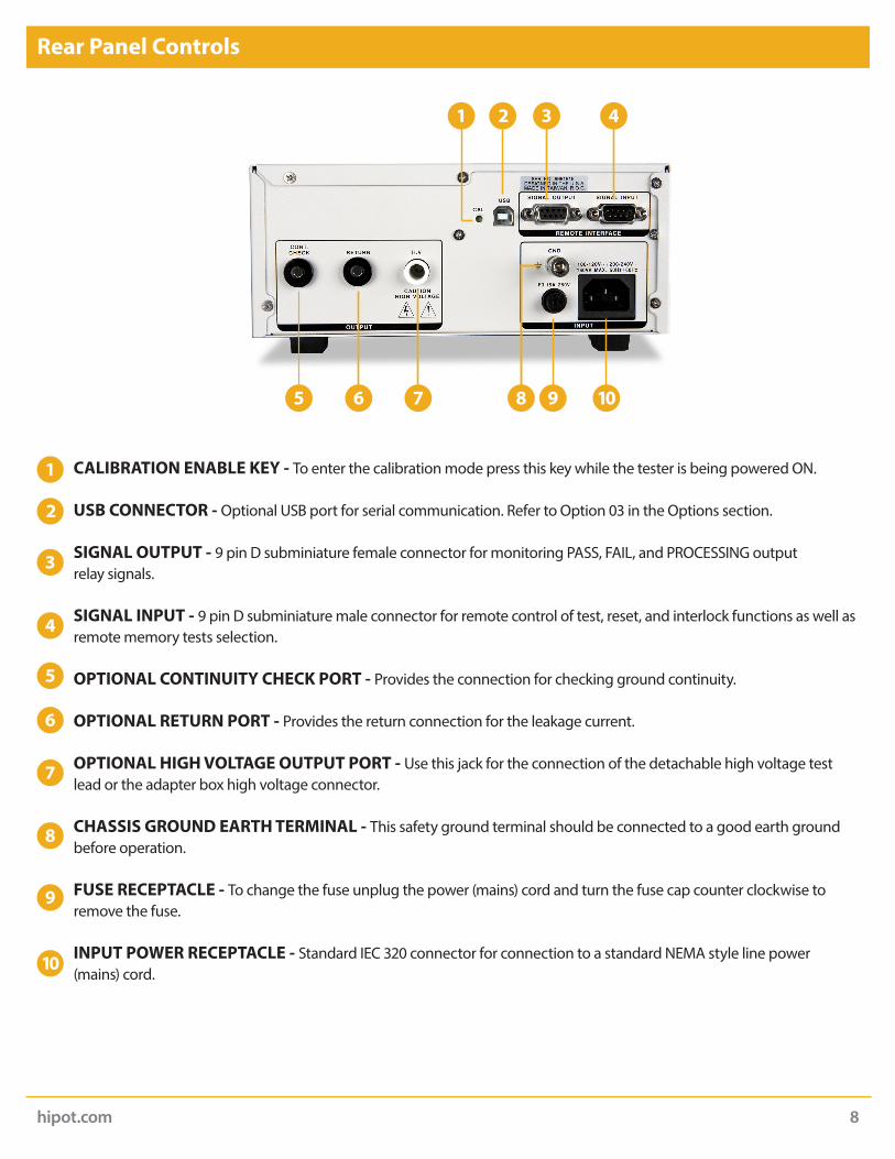
Rear Panel Controls
CALIBRATION ENABLE KEY - To enter the calibration mode press this key while the tester is being powered ON.
USB CONNECTOR - Optional USB port for serial communication. Refer to Option 03 in the Options section. SIGNAL OUTPUT - 9 pin D subminiature female connector for monitoring PASS, FAIL, and PROCESSING output
relay signals.
SIGNAL INPUT - 9 pin D subminiature male connector for remote control of test, reset, and interlock functions as well as remote memory tests selection.
OPTIONAL CONTINUITY CHECK PORT - Provides the connection for checking ground continuity.
OPTIONAL RETURN PORT - Provides the return connection for the leakage current.
OPTIONAL HIGH VOLTAGE OUTPUT PORT - Use this jack for the connection of the detachable high voltage test lead or the adapter box high voltage connector.
CHASSIS GROUND EARTH TERMINAL - This safety ground terminal should be connected to a good earth ground before operation.
FUSE RECEPTACLE - To change the fuse unplug the power (mains) cord and turn the fuse cap counter clockwise to remove the fuse.
INPUT POWER RECEPTACLE - Standard IEC 320 connector for connection to a standard NEMA style line power (mains) cord.
7 8
1
5 6 9 10
2 3 4
1
6
7
8
2
3
4
5
9
hipot.com 9
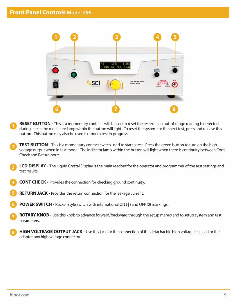
Front Panel Controls Model 298
RESET BUTTON - This is a momentary contact switch used to reset the tester. If an out-of-range reading is detected
during a test, the red failure lamp within the button will light. To reset the system for the next test, press and release this button. This button may also be used to abort a test in progress.
TEST BUTTON - This is a momentary contact switch used to start a test. Press the green button to turn on the high voltage output when in test mode. The indicator lamp within the button will light when there is continuity between Cont. Check and Return ports.
LCD DISPLAY - The Liquid Crystal Display is the main readout for the operator and programmer of the test settings and test results.
CONT CHECK - Provides the connection for checking ground continuity.
RETURN JACK - Provides the return connection for the leakage current.
POWER SWITCH - Rocker-style switch with international ON ( | ) and OFF (0) markings.
ROTARY KNOB - Use this knob to advance forward/backward through the setup menus and to setup system and test parameters.
HIGH VOLTEAGE OUTPUT JACK - Use this jack for the connection of the detachacble high voltage test lead or the adapter box high voltage connector.
1 2 3 4 5
7 86
1
6
7
8
2
3
4
5

hipot.com 10
Rear Panel Controls Model 298
OPTIONAL CONTINUITY CHECK PORT - Provides the connection for checking ground continuity. OPTIONAL RETURN PORT - Provides the return connection for the leakage current.
OPTIONAL HIGH VOLTAGE OUTPUT PORT - Use this jack for the connection of the detachable high voltage test lead or the adapter box high voltage connector.
CALIBRATION ENABLE KEY - Use this jack for the connection of the detachable high voltage test lead or the adapter box high voltage connector.
USB CONNECTOR - Optional USB port for serial communication. Refer to Option 03 in the Options section.
SIGNAL OUTPUT - 9 pin D subminiature female connector for monitoring PASS, FAIL, and PROCESSING output relay signals.
SIGNAL INPUT - 9 pin D subminiature male connector for remote control of test, reset, and interlock functions as well as remote memory tests selection.
CHASSIS GROUND EARTH TERMINAL - This safety ground terminal should be connected to a good earth ground before operation.
INPUT POWER RECEPTACLE - Standard IEC 320 connector for connection to a standard NEMA style line power (mains) cord.
FUSE RECEPTACLE - To change the fuse unplug the power (mains) cord and turn the fuse cap counter clockwise to remove the fuse.
THERMAL FAN - To cool the tester.
1 32 5 7
4 6
8 9 1110
1
6
7
8
2
3
4
5
9

hipot.com 11
Setup Instructions
Power-Up Sequence:
1. Check to be sure the correct input line cord is used.
2. Connect the power input plug into its socket on the rear panel of the tester. The SCI 290 series of testers has an automatic input voltage range selection.
3. Connect the male end of the plug to the grounded AC outlet.
4. Connect the Interlock Disable key to the Signal Input connector on the back panel of the tester. This is required in order to run a test.
5. Turn on the POWER switch located on the lower left hand side of the front panel. Upon powering the tester up, a POWER ON SELF TEST (POST) will automatically be performed. This test will check for the condition of the RAM chips, PCB’s and other critical components. In addition the display will show the following message, with the actual model number and software version number.
6. The tester will recall the last memory program that was active and the display will show the parameters that were programmed into that memory. The tester is now ready for operation.
WARNINGPLEASE BE SURE THAT THE SAFETY GROUND ON THE POWER LINE CORD IS NOT DEFEATED AND THAT YOU ARE CONNECTING TO A GROUNDED POWER SOURCE. ALSO, CONNECT THE REAR PANEL CHASSIS GROUND FOR ADDITIONAL SAFETY.
GroundedPowerSource

hipot.com 12
Getting to Know Your Tester
1. Working with Memories The SCI 290 series of testers are equipped with 5 memory programs numbered 1 through 5. Each memory can be
connected sequentially to the next consecutive memory. Only one test type can be selected for each memory location. However, all 5 memory locations can be programmed and the parameters will be saved in each memory. The tests loaded in each memory location can be executed one at a time or as a sequence.
2. Perform Test Screen The Perform Test Screen displays the
following parameters:
Follow the setup procedures to set the desired parameters. The display will show the either the Hipot test settings or the Insulation Resistance test settings:
*The underscore character may be displayed after the memory number, i.e. M1_. This indicates that another configured test will execute after the displayed setup has completed.
Display* Description
AC Hipot test display
DC Hipot test display
Insulation Resistance test display
hipot.com 13
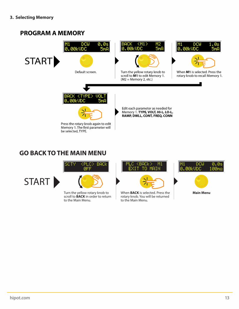
3. Selecting Memory
START
GO BACK TO THE MAIN MENU
Turn the yellow rotary knob to scroll to BACK in order to return to the Main Menu.
Main MenuWhen BACK is selected. Press the rotary knob. You will be returned to the Main Menu.
hipot.com 14
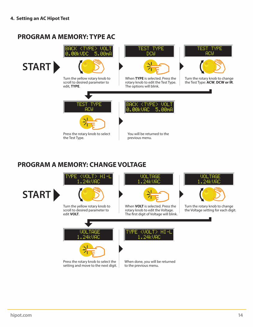
4. Setting an AC Hipot Test
START
PROGRAM A MEMORY: TYPE AC
When TYPE is selected. Press the rotary knob to edit the Test Type. The options will blink.
Turn the yellow rotary knob to scroll to desired parameter to edit, TYPE.
Turn the rotary knob to change the Test Type: ACW, DCW or IR.
Press the rotary knob to select the Test Type.
You will be returned to the previous menu.
START
PROGRAM A MEMORY: CHANGE VOLTAGE
When VOLT is selected. Press the rotary knob to edit the Voltage. The �rst digit of Voltage will blink.
Turn the yellow rotary knob to scroll to desired parameter to edit VOLT.
Turn the rotary knob to change the Voltage setting for each digit.
Press the rotary knob to select the setting and move to the next digit.
When done, you will be returned to the previous menu.

hipot.com 15
START
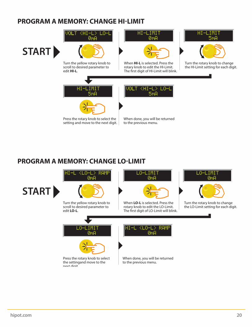
PROGRAM A MEMORY: CHANGE HI-LIMIT
When HI-L is selected. Press the rotary knob to edit the HI-Limit. The �rst digit of HI-Limit will blink.
Turn the yellow rotary knob to scroll to desired parameter to edit HI-L.
Turn the rotary knob to change the HI-Limit setting for each digit.
Press the rotary knob to select the setting and move to the next digit.
When done, you will be returned to the previous menu.
START
PROGRAM A MEMORY: CHANGE LO-LIMIT
When LO-L is selected. Press the rotary knob to edit the LO-Limit. The �rst digit of LO-Limit will blink.
Turn the yellow rotary knob to scroll to desired parameter to edit LO-L.
Turn the rotary knob to change the LO-Limit setting for each digit.
Press the rotary knob to select the settingand move to the next digit.
When done, you will be returned to the previous menu.

hipot.com 16
START
PROGRAM A MEMORY: CHANGE RAMP
When RAMP is selected. Press the rotary knob to edit the Ramp Time.The �rst digit of Ramp Time will blink.
Turn the yellow rotary knob to scroll to desired parameter to edit RAMP.
Turn the rotary knob to change the Ramp Time for each digit.
Press the rotary knob to select thesetting and move to the next digit.
When done, you will be returned to the previous menu.
START
PROGRAM A MEMORY: CHANGE DWELL
When DWLL is selected. Press the rotary knob to edit the Dwell Time. The �rst digit of Dwell Time will blink.
Turn the yellow rotary knob to scroll to desired parameter to edit DWLL.
Turn the rotary knob to change the Ramp Time for each digit.
Press the rotary knob to select the setting and move to the next digit.
When done, you will be returned to the previous menu.

hipot.com 17
PROGRAM A MEMORY: CHANGE CONTINUITY
STARTWhen CONT is selected. Press the rotary knob to edit the Continuity. The options will blink.
Turn the yellow rotary knob to scroll to desired parameter to edit CONT.
Turn the rotary knob to change the Continuity setting: ON or OFF.
Press the rotary knob to select the setting.
When done, you will be promtedto enter a value for HI-Limit.
Then enter a value for LO-Limit. Then enter a value for O�set.
Then enter an o�set valuemanually.
Then press the test button.
Short the Cont. Check lead with the Black Return Lead as shown above
RETURN
POWER
RESET
TEST
H.V.
5KVAC MAX.6KVAC MAX.
CAUTIONHIGH VOLTAGE
CONT.CHECK
AC/DC/IR HIPOT TESTER
MANUAL
AUTO
Press the rotary knob to con�rm.
RETURN
POWER
RESET
TEST
H.V.
5KVAC MAX.6KVAC MAX.
CAUTIONHIGH VOLTAGE
CONT.CHECK
AC/DC/IR HIPOT TESTER
When done, select BACK to returnto the previous menu.
You will be returned to theprevious menu.

hipot.com 18
START
PROGRAM A MEMORY: CHANGE CONNECT
When CONN is selected. Press the rotary knob to edit the Connect Setting. The options will blink.
Turn the yellow rotary knob to scroll to desired parameter to edit CONN.
Turn the rotary knob to change the Connect setting: ON or OFF.
Press the rotary knob to select the setting.
You will be returned to the previous menu.
START
PROGRAM A MEMORY: CHANGE FREQUENCY
When FREQ is selected. Press the rotary knob to edit the Frequency. The options will blink.
Turn the yellow rotary knob to scroll to desired parameter to edit FREQ.
Turn the rotary knob to change the Frequency setting: 50Hz or 60Hz.
Press the rotary knob to select the setting.
You will be returned to the previous menu.
hipot.com 19
START
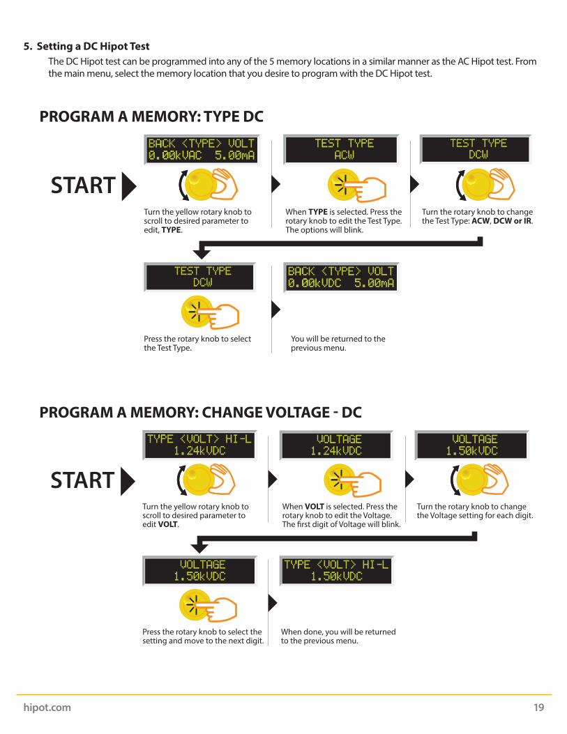
PROGRAM A MEMORY: CHANGE VOLTAGE - DC
When VOLT is selected. Press the rotary knob to edit the Voltage. The �rst digit of Voltage will blink.
Turn the yellow rotary knob to scroll to desired parameter to edit VOLT.
Turn the rotary knob to change the Voltage setting for each digit.
Press the rotary knob to select the setting and move to the next digit.
When done, you will be returned to the previous menu.
START
PROGRAM A MEMORY: TYPE DC
When TYPE is selected. Press the rotary knob to edit the Test Type. The options will blink.
Turn the yellow rotary knob to scroll to desired parameter to edit, TYPE.
Turn the rotary knob to change the Test Type: ACW, DCW or IR.
Press the rotary knob to select the Test Type.
You will be returned to the previous menu.
5. Setting a DC Hipot Test The DC Hipot test can be programmed into any of the 5 memory locations in a similar manner as the AC Hipot test. From
the main menu, select the memory location that you desire to program with the DC Hipot test.
hipot.com 20
START
PROGRAM A MEMORY: CHANGE LO-LIMIT
When LO-L is selected. Press the rotary knob to edit the LO-Limit. The �rst digit of LO-Limit will blink.
Turn the yellow rotary knob to scroll to desired parameter to edit LO-L.
Turn the rotary knob to change the LO-Limit setting for each digit.
Press the rotary knob to select the settingand move to the next digit.
When done, you will be returned to the previous menu.
START
PROGRAM A MEMORY: CHANGE HI-LIMIT
When HI-L is selected. Press the rotary knob to edit the HI-Limit. The �rst digit of HI-Limit will blink.
Turn the yellow rotary knob to scroll to desired parameter to edit HI-L.
Turn the rotary knob to change the HI-Limit setting for each digit.
Press the rotary knob to select the setting and move to the next digit.
When done, you will be returned to the previous menu.

hipot.com 21
START
PROGRAM A MEMORY: CHANGE DWELL
When DWLL is selected. Press the rotary knob to edit the Dwell Time. The �rst digit of Dwell Time will blink.
Turn the yellow rotary knob to scroll to desired parameter to edit DWLL.
Turn the rotary knob to change the Ramp Time for each digit.
Press the rotary knob to select the setting and move to the next digit.
When done, you will be returned to the previous menu.
START
PROGRAM A MEMORY: CHANGE RAMP
When RAMP is selected. Press the rotary knob to edit the Ramp Time.The �rst digit of Ramp Time will blink.
Turn the yellow rotary knob to scroll to desired parameter to edit RAMP.
Turn the rotary knob to change the Ramp Time for each digit.
Press the rotary knob to select thesetting and move to the next digit.
When done, you will be returned to the previous menu.

hipot.com 22
START
PROGRAM A MEMORY: CHANGE CONTINUITY
When CONT is selected. Press the rotary knob to edit the Continuity. The options will blink.
Turn the yellow rotary knob to scroll to desired parameter to edit CONT.
Turn the rotary knob to change the Continuity setting: ON or OFF.
Press the rotary knob to select the setting.
When done, you will be promtedto enter a value for HI-Limit.
Then enter a value for LO-Limit. Then enter a value for O�set.
Then enter an o�set valuemanually.
Then press the test button.
Short the Cont. Check lead with the Black Return Lead as shown above
RETURN
POWER
RESET
TEST
H.V.
5KVAC MAX.6KVAC MAX.
CAUTIONHIGH VOLTAGE
CONT.CHECK
AC/DC/IR HIPOT TESTER
MANUAL
AUTO
Press the rotary knob to con�rm.
RETURN
POWER
RESET
TEST
H.V.
5KVAC MAX.6KVAC MAX.
CAUTIONHIGH VOLTAGE
CONT.CHECK
AC/DC/IR HIPOT TESTER
When done, select BACK to returnto the previous menu.
You will be returned to the previous menu.

hipot.com 23
START
PROGRAM A MEMORY: CHANGE CONNECT
When CONN is selected. Press the rotary knob to edit the Connect Setting. The options will blink.
Turn the yellow rotary knob to scroll to desired parameter to edit CONN.
Turn the rotary knob to change the Connect setting: ON or OFF.
Press the rotary knob to select the setting.
You will be returned to the previous menu.
START
PROGRAM A MEMORY: TYPE IR
When TYPE is selected. Press the rotary knob to edit the Test Type. The options will blink.
Turn the yellow rotary knob to scroll to desired parameter to edit, TYPE.
Turn the rotary knob to change the Test Type: ACW, DCW or IR.
Press the rotary knob to select the Test Type.
You will be returned to the previous menu.
6. Setting an IR Test The IR test can be programmed into any of the 5 memory locations in a similar manner as the AC or DC Hipot test. From
the main menu select the memory location that you desire to program with the IR test.
hipot.com 24
START
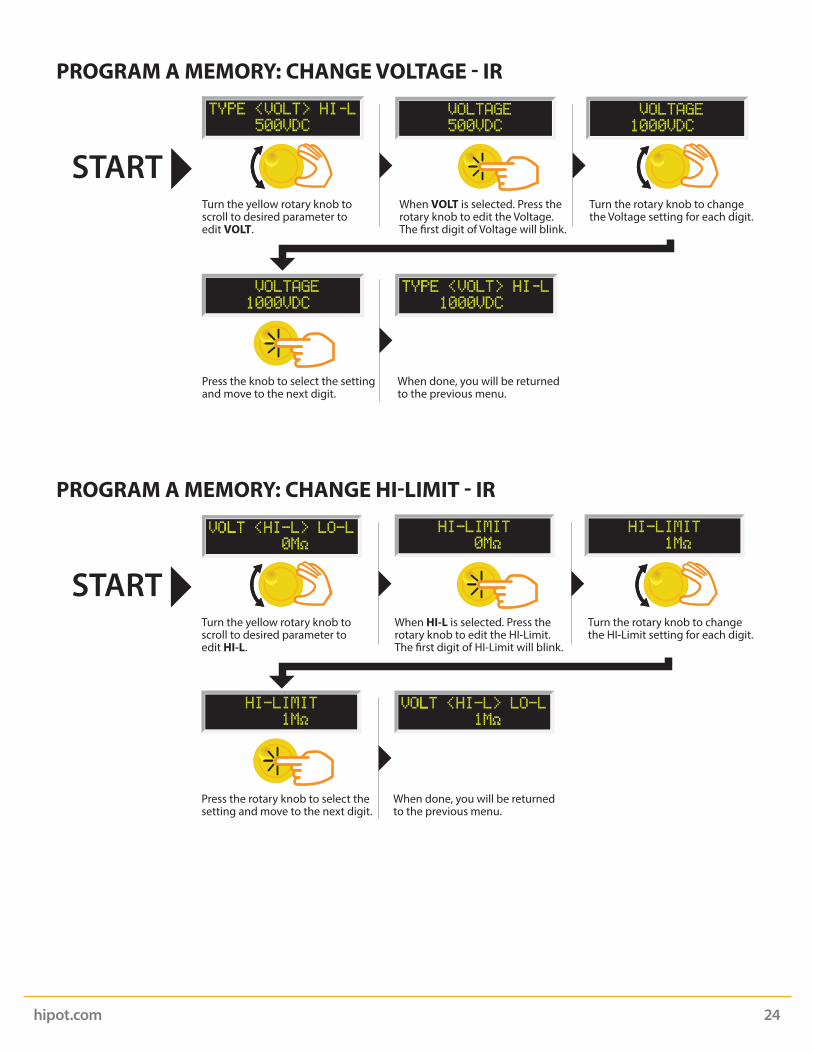
PROGRAM A MEMORY: CHANGE VOLTAGE - IR
When VOLT is selected. Press the rotary knob to edit the Voltage. The �rst digit of Voltage will blink.
Turn the yellow rotary knob to scroll to desired parameter to edit VOLT.
Turn the rotary knob to change the Voltage setting for each digit.
Press the knob to select the settingand move to the next digit.
When done, you will be returned to the previous menu.
START
PROGRAM A MEMORY: CHANGE HI-LIMIT - IR
When HI-L is selected. Press the rotary knob to edit the HI-Limit. The �rst digit of HI-Limit will blink.
Turn the yellow rotary knob to scroll to desired parameter to edit HI-L.
Turn the rotary knob to change the HI-Limit setting for each digit.
Press the rotary knob to select the setting and move to the next digit.
When done, you will be returned to the previous menu.
hipot.com 25
START
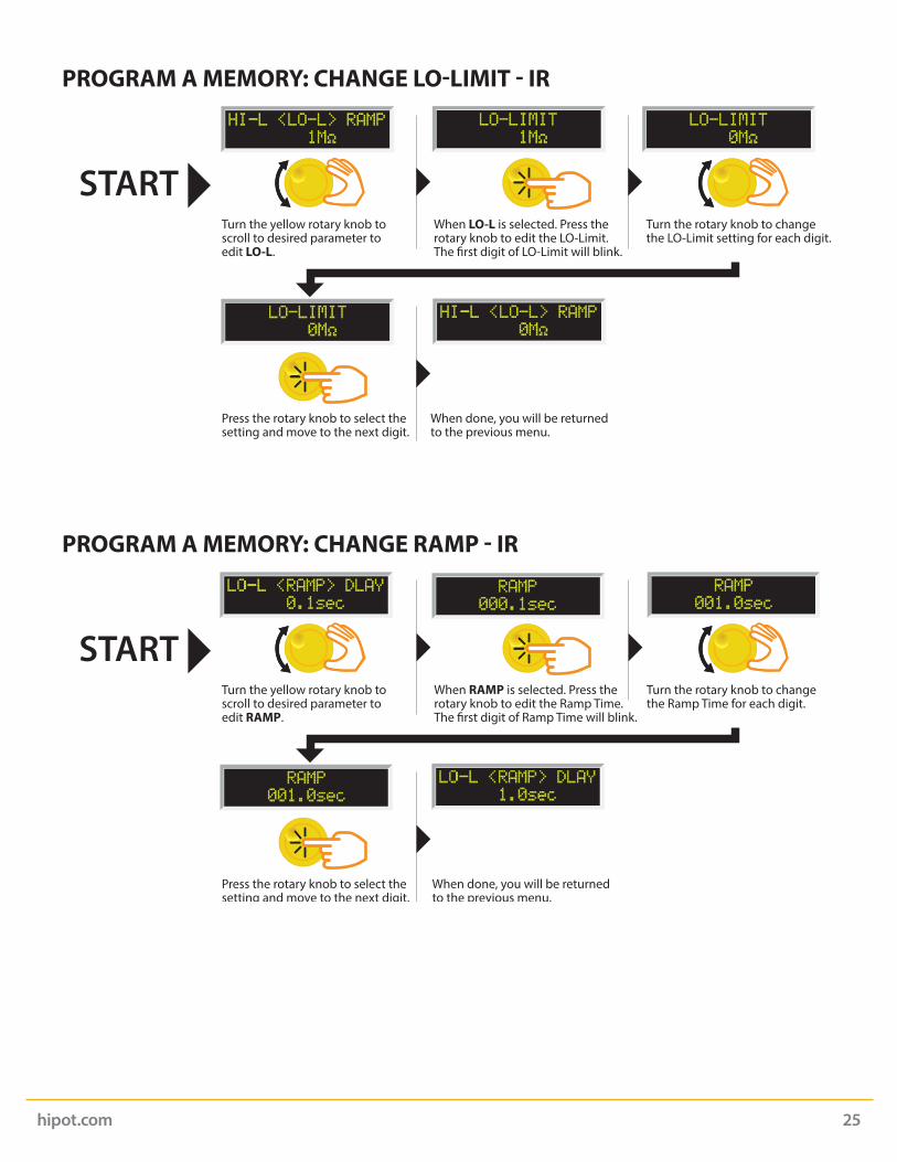
PROGRAM A MEMORY: CHANGE LO-LIMIT - IR
When LO-L is selected. Press the rotary knob to edit the LO-Limit. The �rst digit of LO-Limit will blink.
Turn the yellow rotary knob to scroll to desired parameter to edit LO-L.
Turn the rotary knob to change the LO-Limit setting for each digit.
Press the rotary knob to select the setting and move to the next digit.
When done, you will be returned to the previous menu.
START
PROGRAM A MEMORY: CHANGE RAMP - IR
When RAMP is selected. Press the rotary knob to edit the Ramp Time.The �rst digit of Ramp Time will blink.
Turn the yellow rotary knob to scroll to desired parameter to edit RAMP.
Turn the rotary knob to change the Ramp Time for each digit.
Press the rotary knob to select the setting and move to the next digit.
When done, you will be returned to the previous menu.
hipot.com 26
START
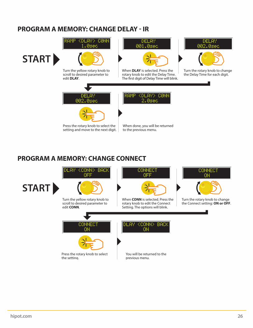
PROGRAM A MEMORY: CHANGE DELAY - IR
When DLAY is selected. Press the rotary knob to edit the Delay Time.The �rst digit of Delay Time will blink.
Turn the yellow rotary knob to scroll to desired parameter to edit DLAY.
Turn the rotary knob to change the Delay Time for each digit.
Press the rotary knob to select the setting and move to the next digit.
When done, you will be returned to the previous menu.
START
PROGRAM A MEMORY: CHANGE CONNECT
When CONN is selected. Press the rotary knob to edit the Connect Setting. The options will blink.
Turn the yellow rotary knob to scroll to desired parameter to edit CONN.
Turn the rotary knob to change the Connect setting: ON or OFF.
Press the rotary knob to select the setting.
You will be returned to the previous menu.
hipot.com 27
System Parameter Descriptions
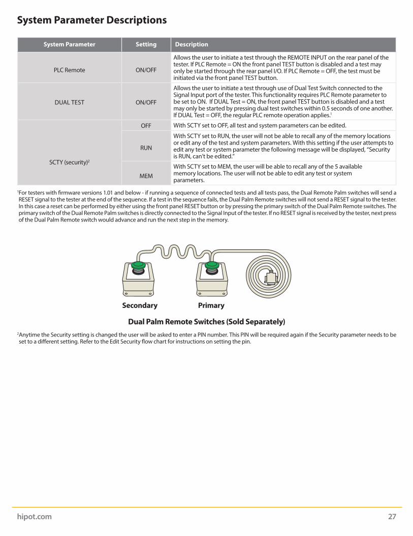
System Parameter Setting Description
PLC Remote ON/OFF
Allows the user to initiate a test through the REMOTE INPUT on the rear panel of the tester. If PLC Remote = ON the front panel TEST button is disabled and a test may only be started through the rear panel I/O. If PLC Remote = OFF, the test must be initiated via the front panel TEST button.
DUAL TEST ON/OFF
Allows the user to initiate a test through use of Dual Test Switch connected to the Signal Input port of the tester. This functionality requires PLC Remote parameter to be set to ON. If DUAL Test = ON, the front panel TEST button is disabled and a test may only be started by pressing dual test switches within 0.5 seconds of one another. If DUAL Test = OFF, the regular PLC remote operation applies.1
SCTY (security)2
OFF With SCTY set to OFF, all test and system parameters can be edited.
RUN
With SCTY set to RUN, the user will not be able to recall any of the memory locations or edit any of the test and system parameters. With this setting if the user attempts to edit any test or system parameter the following message will be displayed, “Security is RUN, can’t be edited.”
MEMWith SCTY set to MEM, the user will be able to recall any of the 5 available memory locations. The user will not be able to edit any test or system parameters.
1 For testers with firmware versions 1.01 and below - if running a sequence of connected tests and all tests pass, the Dual Remote Palm switches will send a RESET signal to the tester at the end of the sequence. If a test in the sequence fails, the Dual Palm Remote switches will not send a RESET signal to the tester. In this case a reset can be performed by either using the front panel RESET button or by pressing the primary switch of the Dual Palm Remote switches. The primary switch of the Dual Remote Palm switches is directly connected to the Signal Input of the tester. If no RESET signal is received by the tester, next press of the Dual Palm Remote switch would advance and run the next step in the memory.
2 Anytime the Security setting is changed the user will be asked to enter a PIN number. This PIN will be required again if the Security parameter needs to be set to a different setting. Refer to the Edit Security flow chart for instructions on setting the pin.
Dual Palm Remote Switches (Sold Separately)
Secondary Primary

hipot.com 28
START
EDIT SECURITY SETTINGS
Turn the yellow rotary knob to scroll to SCTY to edit Security settings.
Default screen. When SCTY is selected. Press the rotary knob to enter the Security settings. The options will blink.
Turn rotary knob to change the Security settings: OFF, RUN or MEM.
Press the rotary knob to select the Security setting option.
Enter a PIN number for the Security setting. Turn rotary knob to enter the PIN.
Press the rotary knob to save thePIN. This PIN will be required whenthe Security setting is edited.
You will be returned to the previous menu.
Setting System Parameters

START
EDIT PLC REMOTE SETTINGS
Turn the yellow rotary knob to scroll to PLC to edit the PLC settings.
Home screen. When PLC is selected. Press the rotary knob to enter the PLC settings. The options will blink.
Turn rotary knob to change the PLC settings: ON or OFF.
Press the rotary knob to select the PLC setting.
You will be returned to the previous menu.
START
PROGRAM A MEMORY: CHANGE DUAL
When DUAL is selected. Press the rotary knob to edit the Connect Setting. The options will blink.
Turn the yellow rotary knob to scroll to desired parameter to edit DUAL.
Turn the rotary knob to change the Dual setting: ON or OFF.
Press the rotary knob to select the setting.
You will be returned to the previous menu.
hipot.com 29

hipot.com 30
Failure Mode Displays
Failure Mode Display* Test Type Description
AC Hipot Displayed if the leakage current exceeds the high limit setting, but does not exceed the metering range.
AC Hipot Displayed if the leakage current does not exceed the low limit setting.
AC Hipot Displayed if there is a short in the DUT during the first 300 mS of test.
AC Hipot Displayed if the leakage current exceeds the metering range and either a short or flashover has occurred during the test.
AC/DC Hipot Displayed if the Continuity test within the hipot test fails.
DC Hipot Displayed if the leakage current exceeds the high limit setting, but does not exceed the metering range.
Using the DisplayTest Mode Displays
Test Mode Display Test Type Description
AC/DC Hipot & IR Displayed when the test voltage is ramping up from 0.0 VAC/VDC to full test voltage.
AC/DC Hipot Displayed when the test voltage has reached full potential. Dwell is the amount of time the potential is held at the set value.
AC/DC Hipot & IR Displayed when a test sequence has passed.
AC/DC Hipot & IR Displayed if the operator elects to stop a test in process. This can be accomplished by pressing the RESET button during the test.
IR Displayed while the test is in process. If the IR value exceeds the set limits, the test will fail after the DELAY time has expired.

hipot.com 31
Failure Mode Display* Test Type Description
DC Hipot Displayed if the leakage current does not exceed the low limit setting.
DC Hipot Displayed if there is a short circuit in the DUT during the test.
DC Hipot Displayed if the leakage current exceeds the metering range and either a short or flashover has occurred during the test.
IR Displayed if the insulation resistance exceeds the high limit setting, but does not exceed the metering range.
IR Displayed if the insulation resistance exceeds the high limit setting, and exceeds the metering range.
IR Displayed if the leakage current does not exceed the low limit setting and is within the metering range.
*For all failures, the red RESET button will illuminate and an alarm will be activated. To stop the alarm, please press the RESET button once. The alarm will stop and the display will retain the failure information. The tester is now ready for the next test. If the RESET button is pressed again, the failure information will be cleared and the display will indicate the setting data of the executed test.
Error Messages
Display Description
This message appears on the display, if the tester’s output reading does not match the setting. When the tester has an output problem and the TEST button is pressed, the Output Error screen will appear. The failure light will illuminate and an alarm will be heard.
Pressing the RESET key will allow you to return to the test mode. The failure light and alarm can be cleared by pressing the RESET button. If Output Error occurs please call the Slaughter Company Customer Support Center at 1-800-504-0055 for assistance.
All of the buttons and keys are not active in this situation. This type of failure permanently locks the tester in the Fatal Error mode and required that the tester be serviced by a SCI authorized service center. Contact the SCI Customer Support Center at 1-800-504-0055 to receive further instruction.
FATAL ERROR 9002 will appear on the display, if the tester’s System data or the Model/Option data are corrupted and do not match the setting.
FATAL ERROR 9003 will appear on the display, if the tester’s Calibration data is corrupted.
This message appears on the screen if the tester detects an over-temperature condition on the power amplifier. The fail light will illuminate and the alarm will be heard. The Reset key can be used to clear this failure condition.

hipot.com 32
Using the Remote I/O
Two 9-pin “D” type connectors are mounted on the rear panel that provides REMOTE-INPUT-OUTPUT control and information.
• These connectors mate with standard 9 pin D-sub-miniature connector provided by the user. • The output mates to a male (plug) connector while the input mates to a female (receptacle) connector. • For best performance, a shielded cable should be used. To avoid ground loops, the shield should not be grounded at both
ends of the cable.
REMOTE I/O Pinouts
Suggested AMP part numbers for interconnecting to the Remote I/O
Part Number Description
205204-4 Plug Shell with Ground Indents
205203-3 Receptacle Shell
745254-7 Crimp Snap-In Pin Contact (for Plug)
745253-7 Crimp Snap-In Socket Contact (for Receptacle)
745171-1 Shielded Cable Clamp (for either Plug or Receptacle)
747784-3 Jackscrew Set (2)
Reviewing Test Results for Multi-step SequencesAfter the test is performed, the test results will be indicated on the front panel display.
Pass: If the DUT passes the test, you will hear a short audible beep and the display will indicate the test result. Fail: If a failure occurs, you will hear a long audible alarm and the red flashing indicator will light up. To stop the alarm, press the RESET button.
The test results from the memories that are executed can be reviewing by turning the rotary knob left or right. Successive rotation of the knob will continue advancing to the next result. The results of the last step in the process will be followed by the first step when scrolling through the results. Results can be reviewed at any time before the next test is executed. All results are cleared at the start of the next test cycle.
SIGNAL OUTPUT SIGNAL INPUT
hipot.com 33
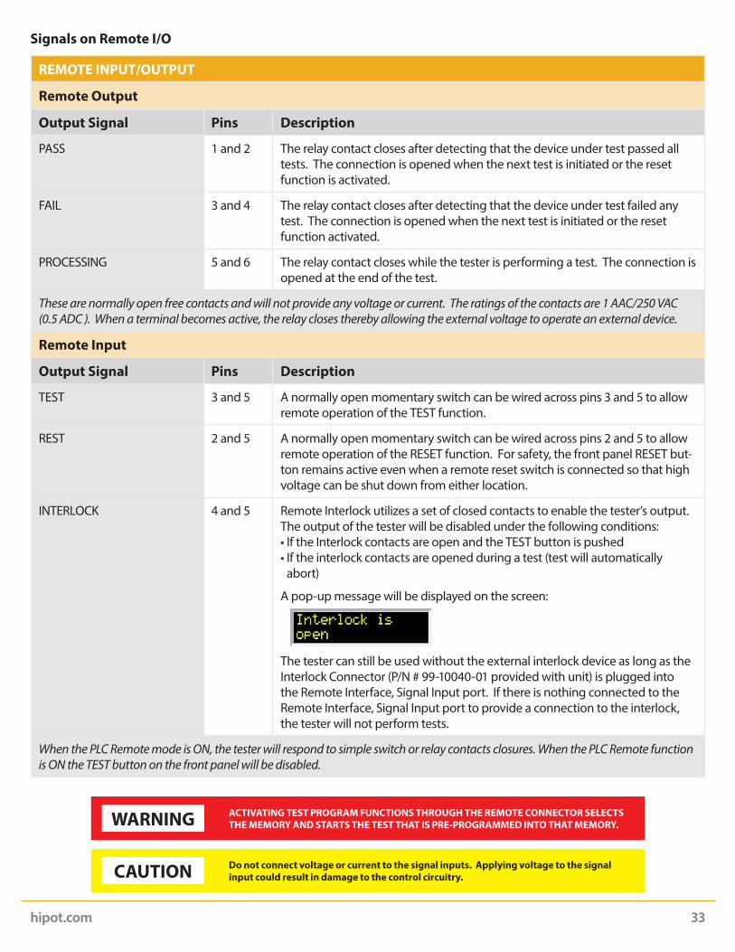
Signals on Remote I/O
REMOTE INPUT/OUTPUT
Remote Output
Output Signal Pins Description
PASS 1 and 2 The relay contact closes after detecting that the device under test passed all tests. The connection is opened when the next test is initiated or the reset function is activated.
FAIL 3 and 4 The relay contact closes after detecting that the device under test failed any test. The connection is opened when the next test is initiated or the reset function activated.
PROCESSING 5 and 6 The relay contact closes while the tester is performing a test. The connection is opened at the end of the test.
These are normally open free contacts and will not provide any voltage or current. The ratings of the contacts are 1 AAC/250 VAC (0.5 ADC ). When a terminal becomes active, the relay closes thereby allowing the external voltage to operate an external device.
Remote Input
Output Signal Pins Description
TEST 3 and 5 A normally open momentary switch can be wired across pins 3 and 5 to allow remote operation of the TEST function.
REST 2 and 5 A normally open momentary switch can be wired across pins 2 and 5 to allow remote operation of the RESET function. For safety, the front panel RESET but-ton remains active even when a remote reset switch is connected so that high voltage can be shut down from either location.
INTERLOCK 4 and 5 Remote Interlock utilizes a set of closed contacts to enable the tester’s output. The output of the tester will be disabled under the following conditions: • If the Interlock contacts are open and the TEST button is pushed• If the interlock contacts are opened during a test (test will automatically
abort)
A pop-up message will be displayed on the screen:
The tester can still be used without the external interlock device as long as the Interlock Connector (P/N # 99-10040-01 provided with unit) is plugged into the Remote Interface, Signal Input port. If there is nothing connected to the Remote Interface, Signal Input port to provide a connection to the interlock, the tester will not perform tests.
When the PLC Remote mode is ON, the tester will respond to simple switch or relay contacts closures. When the PLC Remote function is ON the TEST button on the front panel will be disabled.
WARNING ACTIVATING TEST PROGRAM FUNCTIONS THROUGH THE REMOTE CONNECTOR SELECTS THE MEMORY AND STARTS THE TEST THAT IS PRE-PROGRAMMED INTO THAT MEMORY.
CAUTION Do not connect voltage or current to the signal inputs. Applying voltage to the signal input could result in damage to the control circuitry.
RESET
POWER
TEST RETURN
CAUTIONHIGH VOLTAGE
5KVAC MAX.6KVDC MAX.
H.V.
CONT.CHECK
297AC/DC/IR HIPOT TESTER
FOIL
hipot.com 34
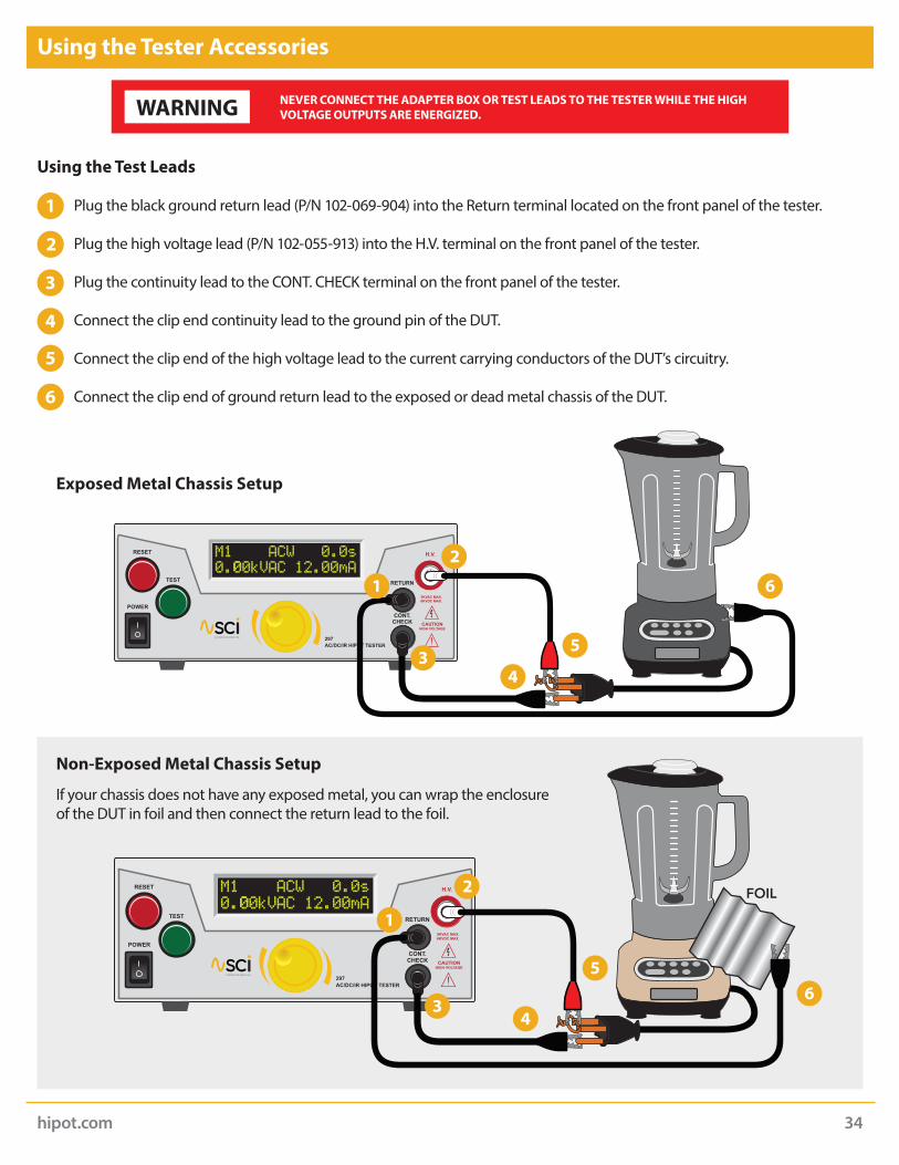
Using the Tester Accessories
WARNING NEVER CONNECT THE ADAPTER BOX OR TEST LEADS TO THE TESTER WHILE THE HIGH VOLTAGE OUTPUTS ARE ENERGIZED.
Using the Test Leads
Plug the black ground return lead (P/N 102-069-904) into the Return terminal located on the front panel of the tester.
Plug the high voltage lead (P/N 102-055-913) into the H.V. terminal on the front panel of the tester.
Plug the continuity lead to the CONT. CHECK terminal on the front panel of the tester.
Connect the clip end continuity lead to the ground pin of the DUT.
Connect the clip end of the high voltage lead to the current carrying conductors of the DUT’s circuitry.
Connect the clip end of ground return lead to the exposed or dead metal chassis of the DUT.
Exposed Metal Chassis Setup
1
2
3
4
6
5
RESET
POWER
TEST RETURN
CAUTIONHIGH VOLTAGE
5KVAC MAX.6KVDC MAX.
H.V.
CONT.CHECK
297AC/DC/IR HIPOT TESTER
2
2
3
3
4
4
6
6
5
5
1
1
Non-Exposed Metal Chassis Setup
If your chassis does not have any exposed metal, you can wrap the enclosure of the DUT in foil and then connect the return lead to the foil.
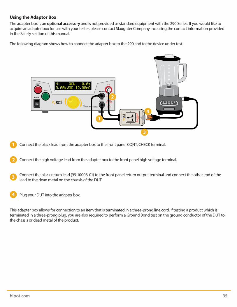
Using the Adaptor BoxThe adapter box is an optional accessory and is not provided as standard equipment with the 290 Series. If you would like to acquire an adapter box for use with your tester, please contact Slaughter Company Inc. using the contact information provided in the Safety section of this manual.
The following diagram shows how to connect the adapter box to the 290 and to the device under test.
Connect the black lead from the adapter box to the front panel CONT. CHECK terminal.
Connect the high voltage lead from the adapter box to the front panel high voltage terminal.
Connect the black return lead (99-10008-01) to the front panel return output terminal and connect the other end of the lead to the dead metal on the chassis of the DUT.
Plug your DUT into the adapter box.
This adapter box allows for connection to an item that is terminated in a three-prong line cord. If testing a product which is terminated in a three-prong plug, you are also required to perform a Ground Bond test on the ground conductor of the DUT to the chassis or dead metal of the product.
hipot.com 35
1
2
3
4
hipot.com 36
Appendix A - Installation and Test Operator Information
Installation
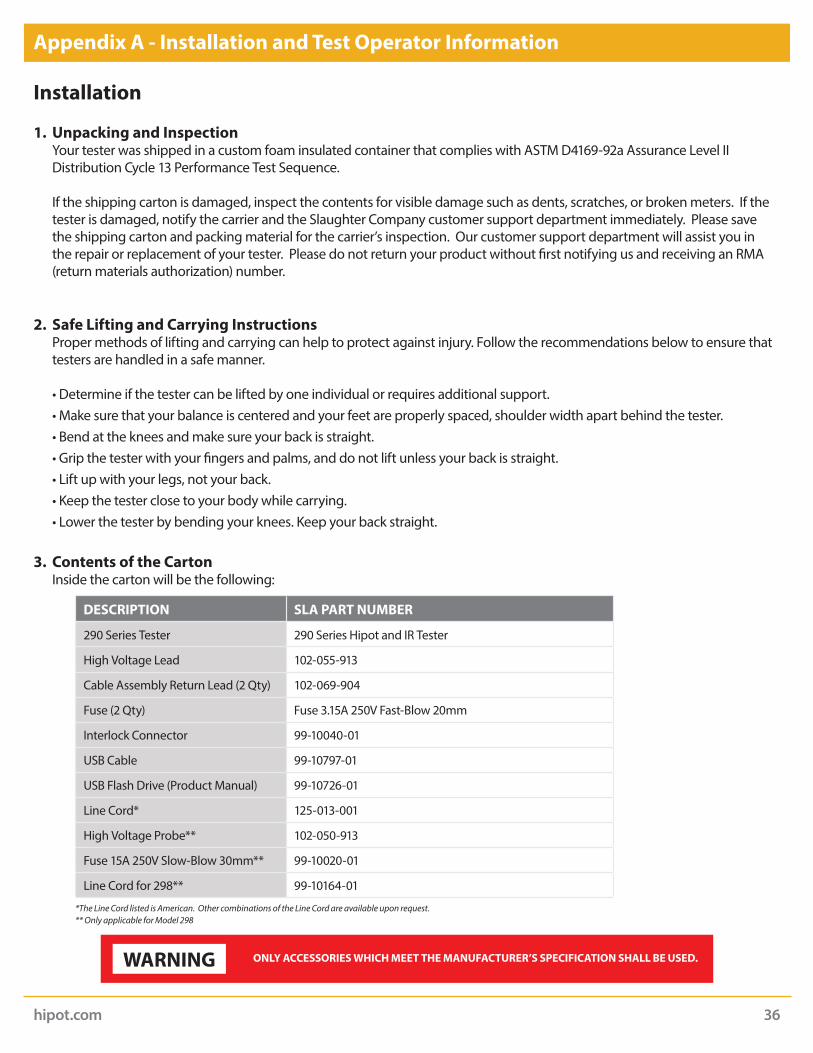
1. Unpacking and Inspection Your tester was shipped in a custom foam insulated container that complies with ASTM D4169-92a Assurance Level II
Distribution Cycle 13 Performance Test Sequence.
If the shipping carton is damaged, inspect the contents for visible damage such as dents, scratches, or broken meters. If the tester is damaged, notify the carrier and the Slaughter Company customer support department immediately. Please save the shipping carton and packing material for the carrier’s inspection. Our customer support department will assist you in the repair or replacement of your tester. Please do not return your product without first notifying us and receiving an RMA (return materials authorization) number.
2. Safe Lifting and Carrying Instructions Proper methods of lifting and carrying can help to protect against injury. Follow the recommendations below to ensure that
testers are handled in a safe manner.
• Determine if the tester can be lifted by one individual or requires additional support. • Make sure that your balance is centered and your feet are properly spaced, shoulder width apart behind the tester. • Bend at the knees and make sure your back is straight. • Grip the tester with your fingers and palms, and do not lift unless your back is straight. • Lift up with your legs, not your back. • Keep the tester close to your body while carrying. • Lower the tester by bending your knees. Keep your back straight.
3. Contents of the Carton Inside the carton will be the following:
DESCRIPTION SLA PART NUMBER
290 Series Tester 290 Series Hipot and IR Tester
High Voltage Lead 102-055-913
Cable Assembly Return Lead (2 Qty) 102-069-904
Fuse (2 Qty) Fuse 3.15A 250V Fast-Blow 20mm
Interlock Connector 99-10040-01
USB Cable 99-10797-01
USB Flash Drive (Product Manual) 99-10726-01
Line Cord* 125-013-001
High Voltage Probe** 102-050-913
Fuse 15A 250V Slow-Blow 30mm** 99-10020-01
Line Cord for 298** 99-10164-01
*The Line Cord listed is American. Other combinations of the Line Cord are available upon request.** Only applicable for Model 298
WARNING ONLY ACCESSORIES WHICH MEET THE MANUFACTURER’S SPECIFICATION SHALL BE USED.

4. Preparation for Use Power Requirements and Line Voltage Selection
5. Power Cable
This tester is shipped with a three-wire power cable. When this cable is connected to an appropriate AC power source, this cable connects the chassis to earth ground. The type of power cable shipped with each tester depends on the country of destination.
Operating Environment
This equipment is intended for indoor use only. The equipment has been evaluated according to Installation Category II and Pollution Degree 2 as specified in IEC 664.
This tester may be operated within the following environmental conditions:
Temperature ....................................................................................41° - 104° F (5° - 40° C)Relative humidity .....................................................................................................20 - 80%Altitude ........................................................................................6,560 feet (2,000 meters)
If the tester is used in a matter not specified by the manufacturer, the protection provided by the tester may be impaired.
WARNING BEFORE CONNECTING POWER TO THIS TESTER, THE PROTECTIVE GROUND (EARTH) TERMINALS OF THIS TESTER MUST BE CONNECTED TO THE PROTECTIVE CONDUCTOR OF THE LINE (MAINS) POWER CORD. THE MAIN PLUG SHALL ONLY BE INSERTED IN A SOCKET OUTLET (RECEPTACLE)
PROVIDED WITH A PROTECTIVE GROUND (EARTH) CONTACT. THIS PROTECTIVE GROUND (EARTH) MUST NOT BE DEFEATED BY THE USE OF AN EXTENSION CORD (POWER CABLE) WITHOUT A PROTECTIVE CONDUCTOR (GROUNDING).
WARNINGDO NOT BLOCK ANY VENTILATION OPENINGS TO PREVENT OVER HEATING OF THE EQUIPMENT. KEEP THE VENTILATION SLITS UNCOVERED DURING OPERATION. FAILURE TO DO SO COULD CAUSE THE TESTER TO OVERHEAT AND MAY DAMAGE INTERNAL COMPONENTS.
CAUTIONThis tester requires a power source of either 115 volts AC ± 10%, 47-63 Hz single phase or 230 volts AC ±10%, 47-63 Hz single phase. In addition, please be sure the correct fuse is selected and installed while the tester is in the off position.
hipot.com 37

Storage and Shipment
Environment
This tester may be stored or shipped in environments with the following limits:
Temperature ...............................................................................-40° - 167° F (-40° - 75°C)Altitude .................................................................................. 50,000 feet (15,240 meters)
The tester should also be protected against temperature extremes which may cause condensation within the tester.
Packaging
Contact our customer support department (1-847-932-3662) for an RMA (return materials authorization) number. Please enclose the tester with all options, accessories, and test leads. Indicate the nature of the problem or type of service needed. Also, please mark the container “FRAGILE” to insure proper handling. Please refer to the RMA number for all correspondence.
Packaging Instructions:
1. Be sure to REMOVE ALL ACCESSORIES and the INTERLOCK DISABLE from the tester.
2. Wrap the tester in a bubble pack or similar foam. Enclose the same information as above.
3. Use a strong double-wall container that is made for shipping instrumentation. 350 lb. test material is adequate.
4. Use a layer of shock-absorbing material 70 to 100 mm (3 to 4 inch) thick around all sides of the tester. Protect the control panel with cardboard.
5. Seal the container securely.
6. Mark the container “FRAGILE” to insure proper handling.
7. Please ship models via Federal Express or UPS air.
8. Please refer in all correspondence to your RMA number.
hipot.com 38

hipot.com 39
Test Operator Safety Considerations
1. Qualifications This tester generates voltages and currents which can cause harmful or fatal electric shock and must only be operated
by a skilled worker trained in its use.
The operator should understand the electrical fundamentals of voltage, current, and resistance.
2. Safety Procedures Operators should be thoroughly trained to follow these and all other applicable safety rules and procedures before they
begin a test. Defeating any safety system should be treated as a serious offense and should result in severe penalties, such as removal from the Hipot testing job. Allowing unauthorized personnel in the area during a test should also be dealt with as a serious offense.
3. Dress Operators should not wear jewelry which could accidentally complete a circuit.
4. Medical Restrictions This tester should not be operated by personnel with heart ailments or devices such as pacemakers.
5. Test Procedures
If the tester has an external safety-ground connection, be sure that this is connected. Then connect the return lead first for any test regardless of whether the device under test is a sample of insulating material tested with electrodes, a component tested with the high voltage test lead, or a cord-connected device with a two or three-prong plug.
Plug in the high voltage test lead only when it is being used. Handle its clip only by the insulator---never touch the clip directly. Be certain that the operator has control over any remote test switches connected to the Hipot. Double-check the return and high voltage connections to be certain that they are proper and secure.
When testing with DC, always discharge the capacitance of the item under test and anything the high voltage may have contacted--such as test fixtures--before handling it or disconnecting the test leads.
Hot stick probes can be used to discharge any capacitance in the item under test as a further safety precaution. A hot stick is a non-conducting rod about two feet long with a metal probe at the end which is connected to a wire. To discharge the device under test, two hot sticks are required. First connect both probe wires to a good earth ground. Then touch one probe tip to the same place the return lead was connected. While holding the first probe in place, touch the second probe tip to the same place where the high voltage lead was connected.
WARNING NEVER PERFORM A HIPOT TEST ON ENERGIZED CIRCUITRY OR EQUIPMENT!
WARNING NEVER TOUCH THE ITEM UNDER TEST OR ANYTHING CONNECTED TO IT WHILE HIGH VOLTAGE IS PRESENT DURING THE HIPOT TEST.

hipot.com 40
6. Test Station
Location Select an area away from the main stream of activity which employees do not walk through in performing their normal
duties. If this is not practical because of production line flow, then the area should be roped off and marked for HIGH VOLTAGE TESTING. No employees other than the test operators should be allowed inside. If benches are placed back-to-back, be especially careful about the use of the bench opposite the test station. Signs should be posted: “DANGER - HIGH VOLTAGE TEST IN PROGRESS - UNAUTHORIZED PERSONNEL KEEP AWAY”.
Power Voltage-Hipot Test Equipment must be connected to a good ground. Be certain that the power wiring to the test bench
is properly polarized and that the proper low resistance bonding to ground is in place.
Power to the test station should be arranged so that it can be shut off by one prominently marked switch located at the entrance to the test area. In the event of an emergency, anyone can cut off the power before entering the test area to offer assistance.
Work Area Perform the tests on a non-conducting table or workbench, if possible. There should not be any metal in the work area
between the operator and the location where products being tested will be positioned.
Position the tester so the operator does not have to reach over the product under test to activate or adjust the tester. If the product or component being tested is small, it may be possible to construct guards or an enclosure, made of a non-conducting material such as clear acrylic, such that the item being tested is within the guards or enclosure during the test, and fit them with switches so that the tester will not operate unless the guards are in place or the enclosure closed. The outlet which is used to provide power to the tester should be easily accessible.
Keep the area clean and uncluttered. All test equipment and test leads not absolutely necessary for the test should be removed from the test bench and put away. It should be clear to both the operator and to any observers which product is being tested, and which ones are waiting to be tested or have already been tested. If the tester is used in a matter not specified by Slaughter Company, Inc. the protection provided by the tester may be impaired.
Do not perform Hipot tests in a combustible atmosphere or in any area where combustible materials are present.
WARNINGTHE MAINS PLUG IS USED AS THE DISCONNECTING DEVICE AND SHALL REMAIN READILY OPERABLE. THE SOCKET-OUTLET SHALL BE INSTALLED NEAR THE EQUIPMENT AND SHALL BE EASILY ACCESSIBLE.
CAUTIONDo not replace the power supply cord with an improperly rated cord. For North American: A UL listed and CSA labeled power cord must be used with the tester in the United States and Canada. The power cord must include a NEMA5-15 style male plug, SVT or SJT cord sets, and be rated for at least 125VAC, 10A, number 16 gauge (or 125VAC, 15A, number 14 gauge) wire
or larger, and the length of the cord does not exceed 2 m must be used. For European: A certified power supply cord not lighter than light PVC sheathed flexible cord according to IEC 60227, designation H03 VV-F or H03 VVH2-F (for equipment mass not exceeding 3 kg), or H05 VV-F or H05 VVH2-F2 (for equipment mass exceeding 3 kg), and be rated for at least 3G 0.75 mm² (for rated current up to 10 A) or 3G 1.0mm² (for rated current over 10 A up to 16 A) wire or larger, and the length of the cord does not exceed 2 m must be used.
KEY SAFETY POINTS TO REMEMBER• Keep unqualified and unauthorized personnel away from the test area.• Arrange the test station in a safe and orderly manner.• Never touch the product or connections during a test.• In case of any problem, turn off the high voltage first.• Properly discharge any item tested with DC before touching connections.

hipot.com 41
Appendix B - 290 Series Tester Specifications
Unless otherwise stated, accuracies are relative to a laboratory standard measurement.
INPUT
Voltage 100 - 120 / 220 - 240V Auto Range, ± 10% variation
Frequency 50 / 60 Hz ± 5%
Fuse 3.15 A / 250V AC Fast Blow15A/250V AC Slow-Blow (Model 298)
HIPOT TEST MODE
Output Rating 5 kV @ 12 mA AC (Models 295, 296 & 297)6 kV @ 5 mA DC (Models 294, 296 & 297)5 kVAC @ 99.9 mA (Model 298)
Voltage Setting Range:
Resolution:Accuracy:
0.00 – 5.00 kV AC 0.00 – 6.00 kV DC0.01 kV± (1.5% of setting + 5 V)
Voltage Display Range:
Resolution: Accuracy:
0.00 – 5.00 kV AC0.00 – 6.00 kV DC0.01 kV± (1.5% of reading + 10 V) < 500 V± (1.5% of reading) ≥ 500 V
Current Display Range:
Resolution: Accuracy:
0.10 – 12.00 mA AC0.02 – 5.00 mA DC0.01 mA± (2% of reading + 2 counts)
Model 298Range:Resolution: Accuracy:
0.10 – 100 mA AC0.01 mA± 2% of setting + 6 counts
HI-Limit Range:Resolution: Accuracy:
Range:Resolution: Accuracy:
0.10 – 12.00 mA AC0.01 mA± (2% of setting + 2 counts)
0.02 – 5.00 mA DC0.01 mA± (2% of setting + 2 counts
Model 298 Range:Resolution: Accuracy:
0.10 – 100 mA AC (Model 298)0.01 mA± 2% of setting + 6 counts
Why use the term “Counts”?Slaughter publishes some specifications using COUNTS which allows us to provide a better indication of the tester’s capabilities across measurement ranges. A COUNT refers to the lowest resolution of the display for a given measurement range. For example, if the resolution for voltage is 1V then 2 counts = 2V.

hipot.com 42
LO-Limit Range:Resolution: Accuracy:
Range:Resolution: Accuracy:
0.00 – 12.00 mA AC0.01 mA± (2% of setting + 2 counts)
0.00 – 5.00 mA DC0.01 mA± (2% of setting + 2 counts)
Model 298 Range:Resolution: Accuracy:
0.00 – 100 mA AC (Model 298)0.01 mA± 2% of setting + 6 counts
Failure Detector Audible and Visual
DC Output Ripple < 5 % at 6 KV / 5 mA Resistive Load
Maximum Capacitive Load in DC Mode
1 uF < 1 kV 0.08 uF < 4 kV0.75 uF < 2 kV 0.04 uF < 5 kV 0.5 uF < 3 kV 0.015 uF < 6 kV
AC Output Waveform Sine Wave, Crest Factor = 1.3 – 1.5
AC Output Frequency Range:Accuracy:
60 or 50 Hz, User Selectable± 0.1%
Output Regulation ± (1% of setting + 5 V) from no load to full load
Dwell Timer Range:Resolution:Accuracy:
0, 0.2 – 60.0 sec (0 = Continuous)0.1 sec± (0.1% + 0.05 sec)
Ramp Timer Range:Resolution:Accuracy:
0.2 – 180.0 sec0.1 sec± (0.1% + 0.05 sec)
GROUND CONTINUITY CHECK
Output Current Range:Accuracy:
0.1 A, Fixed± 0.01 A
HI and LO Limit Range:Resolution:Accuracy:
0.00 – 1.50Ω0.01Ω± (2% of setting + 2 counts)
Offset Range:Resolution:Accuracy:
0.00 – 0.50Ω0.01Ω± (2% of setting + 2 counts)
INSULATION RESISTANCE TEST MODE (Model 297 Only)
Output Voltage Range:Resolution:Accuracy:
100 – 1000 V DC10 V± (1.5% of setting + 3 V)
Voltage Display Range:Resolution:Accuracy:
100 – 1000 V10 V± (1.5% of reading + 5 V)
hipot.com 43
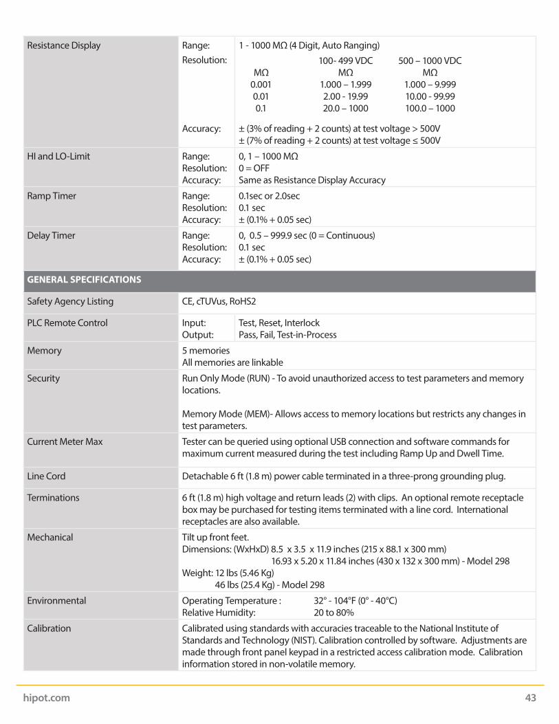
Resistance Display Range:Resolution:
Accuracy:
1 - 1000 MΩ (4 Digit, Auto Ranging)
± (3% of reading + 2 counts) at test voltage > 500V± (7% of reading + 2 counts) at test voltage ≤ 500V
HI and LO-Limit Range:Resolution:Accuracy:
0, 1 – 1000 MΩ0 = OFFSame as Resistance Display Accuracy
Ramp Timer Range:Resolution:Accuracy:
0.1sec or 2.0sec0.1 sec± (0.1% + 0.05 sec)
Delay Timer Range:Resolution:Accuracy:
0, 0.5 – 999.9 sec (0 = Continuous)0.1 sec± (0.1% + 0.05 sec)
GENERAL SPECIFICATIONS
Safety Agency Listing CE, cTUVus, RoHS2
PLC Remote Control Input:Output:
Test, Reset, InterlockPass, Fail, Test-in-Process
Memory 5 memoriesAll memories are linkable
Security Run Only Mode (RUN) - To avoid unauthorized access to test parameters and memory locations.
Memory Mode (MEM)- Allows access to memory locations but restricts any changes in test parameters.
Current Meter Max Tester can be queried using optional USB connection and software commands for maximum current measured during the test including Ramp Up and Dwell Time.
Line Cord Detachable 6 ft (1.8 m) power cable terminated in a three-prong grounding plug.
Terminations 6 ft (1.8 m) high voltage and return leads (2) with clips. An optional remote receptacle box may be purchased for testing items terminated with a line cord. International receptacles are also available.
Mechanical Tilt up front feet.Dimensions: (WxHxD) 8.5 x 3.5 x 11.9 inches (215 x 88.1 x 300 mm)
16.93 x 5.20 x 11.84 inches (430 x 132 x 300 mm) - Model 298Weight: 12 lbs (5.46 Kg)
46 lbs (25.4 Kg) - Model 298
Environmental Operating Temperature : 32° - 104°F (0° - 40°C) Relative Humidity: 20 to 80%
Calibration Calibrated using standards with accuracies traceable to the National Institute of Standards and Technology (NIST). Calibration controlled by software. Adjustments are made through front panel keypad in a restricted access calibration mode. Calibration information stored in non-volatile memory.
MΩ0.0010.010.1
100- 499 VDCMΩ
1.000 – 1.9992.00 - 19.9920.0 – 1000
500 – 1000 VDCMΩ
1.000 – 9.99910.00 - 99.99100.0 – 1000

hipot.com 44
Appendix C - 290 Options
IntroductionThis section contains a list and descriptions of available factory installed options at the time of this printing. The list of options contains an option code number which can be referenced on the model option label on the rear panel of the unit when options are present.
Model Option LabelOn the rear panel of the tester, you will find a label that contains the option code. For example, your options code will appear as follows:fitted with option 01...OPT: 01fitted with option 01 and 02...OPT: 0102
290 Options
Option List
Code Description
01 Rear Output Kit
03 USB Port
04 10 Memory Option
06 3mA AC/DC Current Limit (excludes Model 298)
07 Pulse Mode (Model 295 only)
08 Push to Test Mode (Model 295 only)

hipot.com 45
Option 01- Rear Output KitThis option provides three output connections on the rear panel of the tester. These are the same as the front panel HV, RETURN and CONT. CHECK connections.
Continuity Jack Provides the connection for checking ground continuity.
Return Jack For the connection of the black return test lead or three-prong receptacle adapter box. This jack is always active when performing a test.
High Voltage Jack For the connection of the red high voltage test lead or three-prong receptacle adapter box. The jack is recessed for safety when this lead is not being used. This jack is always active when performing a test.
Option 03 – USB interfaceThis option may be added as a serial type communication protocol. This option provides all of the function control of the USB interface. The Type B USB connector labeled “USB” is for connection of the SCI 290 Series Testers to any compatible PC. When selecting USB Interface, the protocol for interfacing and communicating with a PC can be found in Appendix D: Remote Bus Interface: USB of this manual.
Option 04 – 10 Memory OptionThis option increases the total number of memory locations on the tester from 5 memories to 10 memories. With this option, the tester will display memories M0 to M9 for a total of 10 memory locations.
1
2
3
hipot.com 46
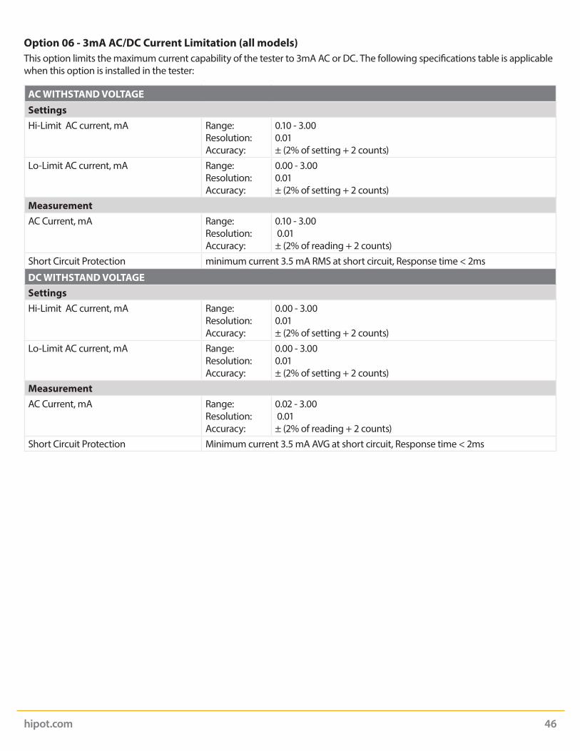
Option 06 - 3mA AC/DC Current Limitation (all models)This option limits the maximum current capability of the tester to 3mA AC or DC. The following specifications table is applicable when this option is installed in the tester:
AC WITHSTAND VOLTAGESettingsHi-Limit AC current, mA Range:
Resolution:Accuracy:
0.10 - 3.000.01± (2% of setting + 2 counts)
Lo-Limit AC current, mA Range:Resolution:Accuracy:
0.00 - 3.000.01± (2% of setting + 2 counts)
MeasurementAC Current, mA Range:
Resolution:Accuracy:
0.10 - 3.00 0.01± (2% of reading + 2 counts)
Short Circuit Protection minimum current 3.5 mA RMS at short circuit, Response time < 2ms
DC WITHSTAND VOLTAGESettingsHi-Limit AC current, mA Range:
Resolution:Accuracy:
0.00 - 3.000.01± (2% of setting + 2 counts)
Lo-Limit AC current, mA Range:Resolution:Accuracy:
0.00 - 3.000.01± (2% of setting + 2 counts)
MeasurementAC Current, mA Range:
Resolution:Accuracy:
0.02 - 3.00 0.01± (2% of reading + 2 counts)
Short Circuit Protection Minimum current 3.5 mA AVG at short circuit, Response time < 2ms

hipot.com 47
PROGRAM A MEMORY: CHANGE PULSE
STA
RT
When the parameter is selected, Press the rotary knob to edit the parameter. The options will blink.
From the home screen, begin by pressing the yellow rotary knob.
Turn the rotary knob to scroll to PULS.
Turn the rotary knob to change the options for the parameter,ON or OFF.
You will then be returned to theprevious menu.
Con�rm by pressing the rotary knob.
Option 07 – Pulse Mode (Model 295 only)This option allows the tester to perform repeated testing upon a failure. The tester will automatically reset after failure for continuous testing. The testing time will not be restarted when automatic reset for continuous testing. With this option installed on the tester an additional test parameter PULS will be available in the menu. To use this option the PULS parameter must be enabled:
The following test specifications will apply if the Pulse Mode option is used:
AC WITHSTAND VOLTAGESettingsHi-Limit AC current, mA Range:
Resolution:Accuracy:
0.10 - 3.000.01± (2% of setting + 2 counts)
Lo-Limit AC current, mA Range:Resolution:Accuracy:
0.00 - 3.000.01± (2% of setting + 2 counts)
Dwell Time, second Range:
Resolution:Accuracy:
Pulse, 0.2-60.0Pulse: automatic reset after failure for continuous testing. 0.1± (0.1% of setting + 0.05 sec)
MeasurementAC Current, mA Range:
Resolution:Accuracy:
0.10 - 3.00 0.01± (2% of reading + 2 counts)

hipot.com 48
PROGRAM A MEMORY: CHANGE HOLDST
ART
When the parameter is selected, press the rotary knob to edit the parameter, the options will blink.
From the home screen, begin by pressing the yellow rotary knob.
Turn the rotary knob to scroll to HOLD.
Turn the rotary knob to change the options for the parameter,ON or OFF.
You will then be returned to theprevious menu.
Con�rm by pressing the rotary knob.
Option 08 – Push to Test ModeWith this option installed an extra parameter called HOLD appears in the ACW test setup. When HOLD is set to ON, the DWELL parameter in the test setup disappears. This allows the user to press and hold the TEST button to execute the test and run it continuously or for any desired time. Once the TEST button is released the test will abort.

hipot.com 49
Appendix D - Remote BUS Interface: USB
This section provides information on the proper use and configuration of bus remote interface. The USB remote interface is optional on all 290 Series models. Please see the OPTIONS section of the manual for details.
USB InterfaceThis interface provides all of the control commands and parameter setting commands. All commands can be found in the command list of this manual. The USB interface card requires you to download a driver in order for the instrument to recognize the USB interface. The driver can be found on the Slaughter Company, Inc. website:
www.hipot.com/products/290.aspx
Click on “USB Driver” to download the driver. This link contains an automatic extract and install program. Follow the instructions of the installation program to initialize the driver install. NOTE: The USB port acts as a USB to RS-232 converter. As a result, the PC will recognize the USB port as a virtual COM port.
The COM port should have the following configuration. 9600 baud, 8 data bits, 1 stop bit, no parity. This interface does not support XON/XOFF protocol or any hardware handshaking.
When sending command over the USB bus, the tester will send a response string of 06 hex or 6 decimal, the Acknowledge (ACK) ASCII control code if the transfer was recognized and completed by the tester. If there is an error with the command string that is sent, the tester will respond with 15 hex or 21 decimal, the Not Acknowledge (NAK) ASCII control code. The ACK or NAK response allows for software handshaking, to monitor and control data flow. When requesting data from the tester, it will automatically send the data back to the controller input buffer. The controller input buffer will accumulate data being sent from the tester including the ACK and NAK response strings, until it has been read by the controller.
USB Interface Command ListThe USB bus will automatically send any response back to the controller’s input buffer. Note that the commands are case sensitive and must be typed in capital letters. Each command string should be terminated by the ASCII control code, New Line <NL>, or OAh.
The following conventions are used to describe the commands syntax for the 290 Series testers. Braces ({ }) enclose each parameter for a command string. Triangle brackets (< >) indicate that you must substitute a value for the enclosed parameter. The Pipe ( | ) is used to separate different parameter options for a command. The command and the parameter data must be separated with a space. All commands that end with a question mark (?) are query commands and require an IEEE-488 read command to retrieve the data from the device’s output buffer.
Test Execution CommandsThe following commands are used to control actual output voltage and current from the tester. Please observe all safety precautions.
TEST - Starts the test sequence at the selected step loaded into memory (RAM).
RESET - Stop or abort a test. Also used to reset a latched failure condition.
SACO - Set the offset for the Continuity test. The cables and any test fixture should be connected before executing the command. This command will perform an actual test and all safety precautions should be observed when using this command.
Command Description
TEST Execute a Test
RESET Abort a Test in Process or Reset Failures
SACO Set Continuity Auto Offset

hipot.com 50
Memory Location Edits and Companion QueriesThe following commands are used to create or modify Test Setup at each Memory Locations.
FL <memory location number> - Load a memory location from non-volatile memory into random access memory RAM.
The parameter values should use complete text and not use the coded values that are associated with the individual parameter setting commands. Such as “ON” and “OFF” and any toggle field that use words or phrases like “OPEN”, “CLOSE”. The LS? companion command will also list all parameters in complete text as they appear on the setting screen.
FL? - Query the memory location of the current selection.
Command Description Value
FL <memory location number> Load Test Located at Memory Location
Memory location number = 1-5
FL? Query Memory Location
1-5
SAA Add ACW Test
SAD Add DCW Test
SAI Add IR Test
ADD <ACW,p,p,p,p,p,p,p,p,p,p,p> Add all parameters for ACW Test
ACW, Voltage(kV), HI-Limit(mA), LO-Limit(mA), Ramp(s), Dwell(s), Continuity(ON/OFF), Cont. HI-Limit(Ω), Cont. LO-Limit(Ω), Cont. Offset(Ω), Frequency, Connect(ON/OFF)
ADD <DCW,p,p,p,p,p,p,p,p,p,p> Add all parameters for DCW Test
DCW, Voltage(kV), HI-Limit(mA), LO-Limit(mA), Ramp(s), Dwell(s), Continuity(ON/OFF), Cont. HI-Limit(Ω), Cont. LO-Limit(Ω), Cont. Offset(Ω), Connect(ON/OFF)
ADD <IR,p,p,p,p,p,p> Add all parameters for IR Test
IR, Voltage(V), HI-Limit(Ω), LO-Limit(Ω), Ramp(s), Delay(s), Connect (ON/OFF)
ACW DCW IR
1 Voltage Voltage Voltage
2 HI-Limit HI-Limit HI-Limit
3 LO-Limit LO-Limit LO-Limit
4 Ramp Up Ramp Up Ramp Up
5 Dwell Dwell Delay
6 Continuity (ON/OFF) Continuity (ON/OFF) Connect (ON/OFF)
7 Continuity HI-Limit Continuity HI-Limit
8 Continuity LO-Limit Continuity LO-Limit
9 Continuity Offset Continuity Offset
10 Frequency Connect (ON/OFF)
11 Connect (ON/OFF)

hipot.com 51
Test Parameter Editing CommandsThese commands are used to modify the test parameter within each memory. These commands require a parameter value to be included with the command. The companion query command will read the parameter. The writing of the parameter requires that the unit not be included with the value, only the numeric value should be included with the command. Also when the query commands are used the response will not include the units characters. Many of the commands will function the same way for multiple test types however the input range may be different and therefore used a different possible set of values.
Command Name Test Types Values
EV <value>EV?
Edit Voltage ACWDCWIR
0.00 – 5.00 (kV)0.00 – 6.00 (kV)100 – 1000 (V)
EH < value >EH?
Edit HI-Limit ACWDCWIR
0.10 – 12.00 (mA)0.02 – 5.00 (mA)0, 1- 1000 (MΩ)0 = Off
EL < value >EL?
Edit LO-Limit ACWDCWIR
0.10 – 12.00 (mA)0.02 – 5.00 (mA)0, 1- 1000 (MΩ) 0 = Off
ERU < value >ERU ?
Edit Ramp ACWDCWIR
0.2 – 180.0 (sec)0.2 – 180.0 (sec).1, 2.0 (sec)
EDW < value >EDW?
Edit Dwell ACWDCW
0.0, 0.2 – 60.0s0.0, 0.2 – 60.0s
0.0 = Continuous
EDE < value >EDE?
Edit Delay IR 0.0, 0.5 - 999.9s
0.0 = Continuous
ECT {1|0}ECT?
Edit Continuity ACWDCW
1=On, 0=Off
ECH < value >ECH?
Edit Continuity HI-Limit ACWDCW
0.00 – 1.50 (Ω)
ECL < value >ECL?
Edit Continuity LO-Limit ACWDCW
0.00 – 1.50 (Ω)
ECO < value >ECO?
Edit Continuity Offset ACWDCW
0.00 – 0.50 (Ω)
EF {1|0}EF?
Edit Frequency ACW 1=60 Hz, 0=50 Hz
ECC {1|0}ECC?
Edit Connect ACWDCWIR
1=On, 0=Off

hipot.com 52
System Parameter Editing Commands and Companion QueriesThese commands are used to modify the system parameters for the tester. These commands require a parameter value to be included with the command.
Query CommandsThese query commands will retrieve data from the tester. These commands include functions for retrieving test data, test results and remote hardware.
TD? - Read the active data being displayed on the LCD display while the test is in process. It will also read the last data taken when the test sequence has completed. Each parameter is separated by commas and includes memory location, test type, test status, and metering. The syntax for this command response is {memory - step, test type, status, meter 1, meter 2, meter 3}. {Memory, GND, Status, Current(A), Resistance(mΩ), Time(s)}
RD <step number>? - Read the results for an individual memory location. Each parameter is separated by commas and includes memory location, test type, test status, and metering. The syntax for this command response is {memory - step, test type, status, meter 1, meter 2, meter 3}. {Memory, GND, Status, Current(A), Resistance(mΩ), Time(s)} RR? - Read the remote Reset input signal. When the remote reset has to be activated by closing the contacts the query will return a value of 0 to indicate the tester is being Reset.
Command Name Value
SPR {1|0}SPR?
PLC Remote ON/OFF 1=On, 0=Off
SEC < 0 > Edit Security OFF 0=Off
SEC < value, mmm>SEC?
Edit Security ON, Passcode
1=RUN, 2=MEM, mmm = 000 – 999 (Passcode)
Command Name Value
TD? List Testing Data Data from test in Process
RD <memory location>? Result Data Query by memory locaiton
1-5
RR? Read Reset Query 1=Open, 0=Closed
RI? Read Interlock Query 1=Open, 0=Closed
RDM Read Current Max Maximum current measured during the test including Ramp Up and Dwell Time
LS? List Step Parameters Memory, GND, Current(A), HI-Limit(mΩ), LO-Limit(mΩ), Dwell(s), Frequency(Hz), Offset(mΩ), Connect
LS <memory location>? List Step Parameters by memory location
Memory Location = 1-5
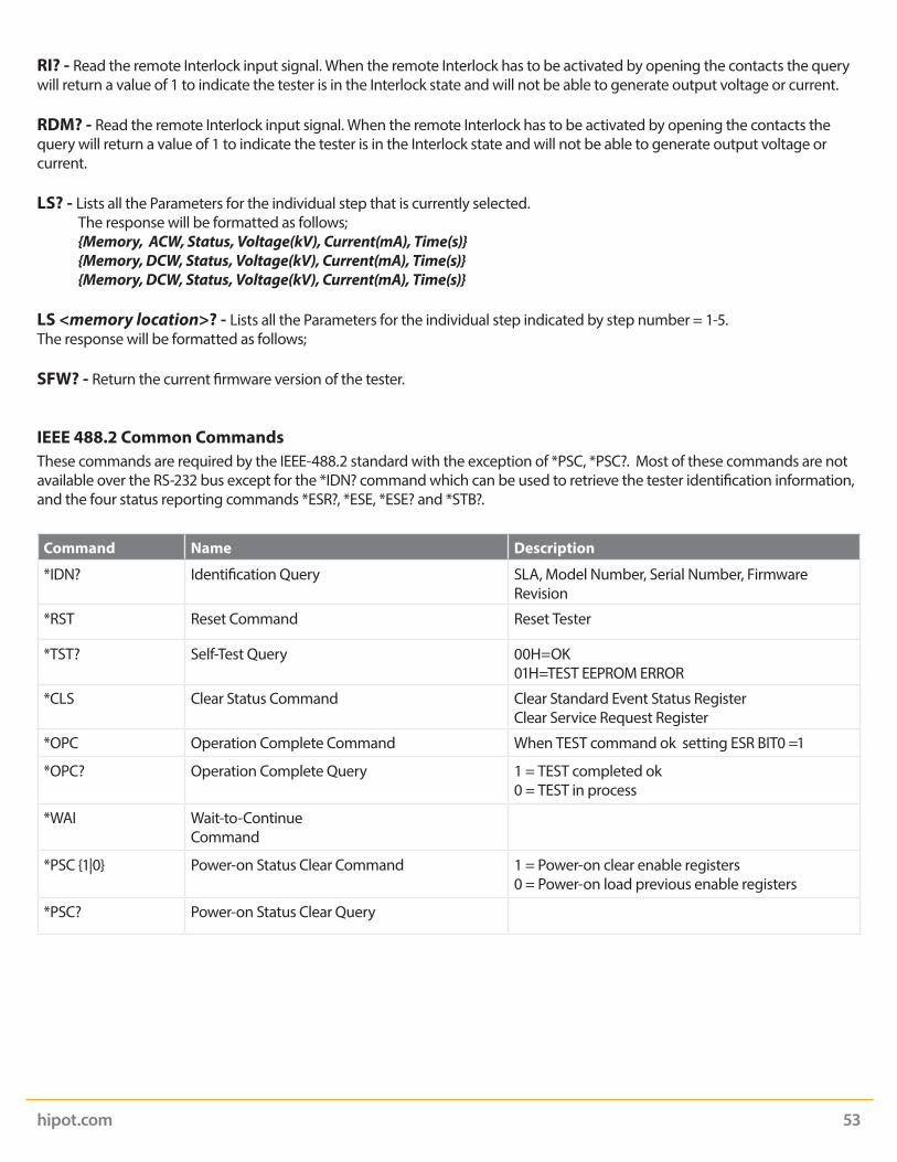
hipot.com 53
RI? - Read the remote Interlock input signal. When the remote Interlock has to be activated by opening the contacts the query will return a value of 1 to indicate the tester is in the Interlock state and will not be able to generate output voltage or current.
RDM? - Read the remote Interlock input signal. When the remote Interlock has to be activated by opening the contacts the query will return a value of 1 to indicate the tester is in the Interlock state and will not be able to generate output voltage or current.
LS? - Lists all the Parameters for the individual step that is currently selected. The response will be formatted as follows; {Memory, ACW, Status, Voltage(kV), Current(mA), Time(s)} {Memory, DCW, Status, Voltage(kV), Current(mA), Time(s)} {Memory, DCW, Status, Voltage(kV), Current(mA), Time(s)}
LS <memory location>? - Lists all the Parameters for the individual step indicated by step number = 1-5.The response will be formatted as follows; SFW? - Return the current firmware version of the tester.
IEEE 488.2 Common CommandsThese commands are required by the IEEE-488.2 standard with the exception of *PSC, *PSC?. Most of these commands are not available over the RS-232 bus except for the *IDN? command which can be used to retrieve the tester identification information, and the four status reporting commands *ESR?, *ESE, *ESE? and *STB?.
Command Name Description
*IDN? Identification Query SLA, Model Number, Serial Number, Firmware Revision
*RST Reset Command Reset Tester
*TST? Self-Test Query 00H=OK01H=TEST EEPROM ERROR
*CLS Clear Status Command Clear Standard Event Status RegisterClear Service Request Register
*OPC Operation Complete Command When TEST command ok setting ESR BIT0 =1
*OPC? Operation Complete Query 1 = TEST completed ok 0 = TEST in process
*WAI Wait-to-Continue Command
*PSC {1|0} Power-on Status Clear Command 1 = Power-on clear enable registers 0 = Power-on load previous enable registers
*PSC? Power-on Status Clear Query
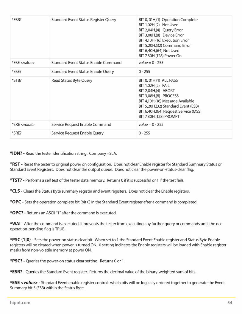
hipot.com 54
*ESR? Standard Event Status Register Query BIT 0, 01H,(1) Operation CompleteBIT 1,02H,(2) Not UsedBIT 2,04H,(4) Query ErrorBIT 3,08H,(8) Device ErrorBIT 4,10H,(16) Execution ErrorBIT 5,20H,(32) Command ErrorBIT 6,40H,(64) Not UsedBIT 7,80H,(128) Power On
*ESE <value> Standard Event Status Enable Command value = 0 - 255
*ESE? Standard Event Status Enable Query 0 - 255
*STB? Read Status Byte Query BIT 0, 01H,(1) ALL PASSBIT 1,02H,(2) FAILBIT 2,04H,(4) ABORTBIT 3,08H,(8) PROCESSBIT 4,10H,(16) Message AvailableBIT 5,20H,(32) Standard Event (ESB)BIT 6,40H,(64) Request Service (MSS)BIT 7,80H,(128) PROMPT
*SRE <value> Service Request Enable Command value = 0 - 255
*SRE? Service Request Enable Query 0 - 255
*IDN? - Read the tester identification string. Company =SLA.
*RST - Reset the tester to original power on configuration. Does not clear Enable register for Standard Summary Status or Standard Event Registers. Does not clear the output queue. Does not clear the power-on-status-clear flag.
*TST? - Performs a self test of the tester data memory. Returns 0 if it is successful or 1 if the test fails.
*CLS - Clears the Status Byte summary register and event registers. Does not clear the Enable registers.
*OPC - Sets the operation complete bit (bit 0) in the Standard Event register after a command is completed.
*OPC? - Returns an ASCII “1” after the command is executed.
*WAI - After the command is executed, it prevents the tester from executing any further query or commands until the no-operation-pending flag is TRUE.
*PSC {1|0} - Sets the power-on status clear bit. When set to 1 the Standard Event Enable register and Status Byte Enable registers will be cleared when power is turned ON. 0 setting indicates the Enable registers will be loaded with Enable register masks from non-volatile memory at power ON.
*PSC? - Queries the power-on status clear setting. Returns 0 or 1.
*ESR? - Queries the Standard Event register. Returns the decimal value of the binary-weighted sum of bits.
*ESE <value> - Standard Event enable register controls which bits will be logically ordered together to generate the Event Summary bit 5 (ESB) within the Status Byte.

hipot.com 55
*ESE? - Queries the Standard Event enable register. Returns the decimal value of the binary-weighted sum of bits.
*STB? - Read the Status Byte. Returns the decimal value of the binary-weighted sum of bits.
*SRE <value> - Service Request enable register controls which bits from the Status Byte should be use to generate a service request when the bit value = 1.
*SRE? - Queries the Service Request enable register. Returns the decimal value of binary-weighted sum of bits.

hipot.com 56
Appendix E - Replacement Parts List - Model 290
Part Number QTY Reference Designator
Description
Supplied Accessories
99-10020-01 2 Fuse 3.15A 250V Fast-Blow 20mm
99-10040-01 1 Interlock Connector
102-069-904 2 Cable Assembly Return Lead
102-055-913 1 High Voltage Lead
125-013-001 1 Cable Input Cordset USA
99-10164-01* 1 Cable Input Cordset USA
99-10797-01 1 USB Cable
99-10726-01 1 USB Flash Drive (Product Manual)
99-10656-01* 2 Fuse 15A 250V Slow-Blow 30mm
102-050-913* 1 High Voltage Probe
Panel Components
99-10297-01 1 Fuse Holder 20mm
99-10727-01 1 High Voltage Connector
99-10017-01 2 Return Connector
99-10312-01 1 Power Switch 2P/15A
99-10016-01 1 Earth Connector
99-10735-01 1 Rotary Knob
330-113-001 1 TEST Test Switch Green Lighted
330-113-002 1 RESET Reset Switch Red Lighted
99-10763-01 1 Feet Kit w/o Rubber Inserts
175-974-002 2 Rubber Insert for Front Feet
99-10762-01 2 Rubber Insert for Rear Feet
99-10736-01 1 16x2 OLED LCD
175-936-002 1 Case Handle
99-10650-01* 1 Fuse Holder 30mm
99-10850-01* 1 16x2 OLED LCD
PCB Assemblies
99-10745-01 1 AMGSP7100 Amplifier Board
99-10746-01 1 CNTSG7100 Continuity Board
99-10747-01 1 CONSG7100 Main Control Board
99-10748-01 1 EVRSG7100 Encoder Board
99-10749-01 1 HRYSG7100 High Voltage Relay Board
99-10750-01 1 LEDM001B LED Assembly
Internal Components
99-10751-01 1 T2 High Voltage Output Transformer*Only applicable for Model 298

hipot.com 57
Appendix F - Service and Maintenance
User ServiceTo prevent electric shock do not remove the tester cover. There are no user serviceable parts inside. Routine maintenance or cleaning of internal parts is not necessary. Any external cleaning should be done with a clean dry or slightly damp cloth. Avoid the use of cleaning agents or chemicals to prevent any foreign liquid from entering the cabinet through ventilation holes or damaging controls and switches. Also some chemicals may damage plastic parts or lettering. Schematics, when provided, are for reference only. Any replacement cables and high voltage components should be acquired directly from Slaughter Company, Inc. Refer servicing to a SCI. authorized service center.
Service IntervalThe tester and its power cord, test leads, and accessories must be returned at least once a year to a SCI authorized service center for calibration and inspection of safety related components. SCI will not be held liable for injuries suffered if the tester is not returned for its annual safety check and maintained properly.
User ModificationsUnauthorized user modifications will void your warranty. SCI will not be responsible for any injuries sustained due to unauthorized equipment modifications or use of parts not specified by SCI Testers returned to SCI with unsafe modifications will be returned to their original operating condition at your expense.
SCI28105 N. Keith DriveLake Forest, IL 60045-4546 USA
Phone 1 (847) 932-3662 or 1 (800) 504-0055 Fax 1 (847) 932-3665Email [email protected] hipot.com
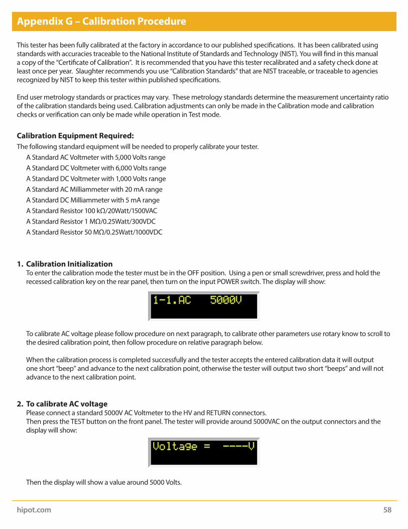
hipot.com 58
Appendix G – Calibration Procedure
This tester has been fully calibrated at the factory in accordance to our published specifications. It has been calibrated using standards with accuracies traceable to the National Institute of Standards and Technology (NIST). You will find in this manual a copy of the “Certificate of Calibration”. It is recommended that you have this tester recalibrated and a safety check done at least once per year. Slaughter recommends you use “Calibration Standards” that are NIST traceable, or traceable to agencies recognized by NIST to keep this tester within published specifications.
End user metrology standards or practices may vary. These metrology standards determine the measurement uncertainty ratio of the calibration standards being used. Calibration adjustments can only be made in the Calibration mode and calibration checks or verification can only be made while operation in Test mode.
Calibration Equipment Required:The following standard equipment will be needed to properly calibrate your tester. A Standard AC Voltmeter with 5,000 Volts range A Standard DC Voltmeter with 6,000 Volts range A Standard DC Voltmeter with 1,000 Volts range A Standard AC Milliammeter with 20 mA range A Standard DC Milliammeter with 5 mA range A Standard Resistor 100 kΩ/20Watt/1500VAC A Standard Resistor 1 MΩ/0.25Watt/300VDC A Standard Resistor 50 MΩ/0.25Watt/1000VDC
1. Calibration Initialization To enter the calibration mode the tester must be in the OFF position. Using a pen or small screwdriver, press and hold the
recessed calibration key on the rear panel, then turn on the input POWER switch. The display will show:
To calibrate AC voltage please follow procedure on next paragraph, to calibrate other parameters use rotary know to scroll to the desired calibration point, then follow procedure on relative paragraph below.
When the calibration process is completed successfully and the tester accepts the entered calibration data it will output one short “beep” and advance to the next calibration point, otherwise the tester will output two short “beeps” and will not advance to the next calibration point.
2. To calibrate AC voltage Please connect a standard 5000V AC Voltmeter to the HV and RETURN connectors. Then press the TEST button on the front panel. The tester will provide around 5000VAC on the output connectors and the
display will show:
Then the display will show a value around 5000 Volts.
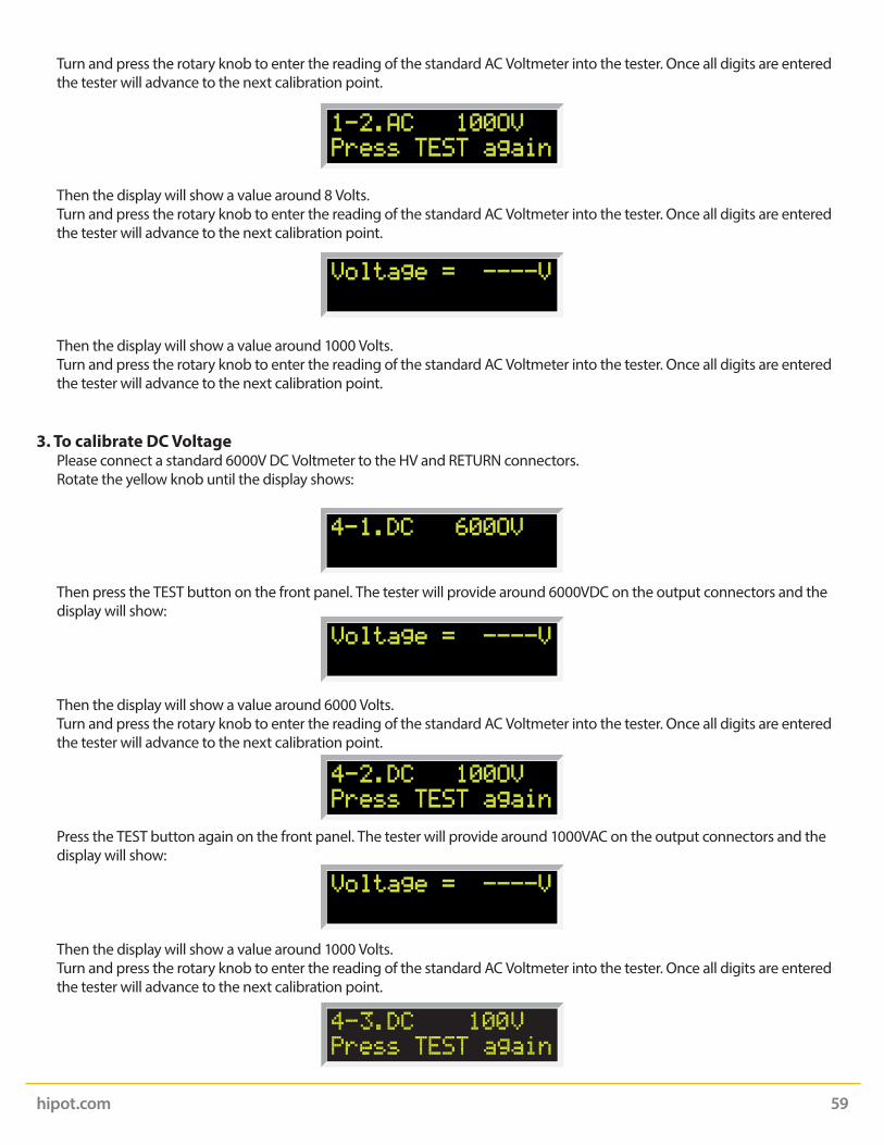
hipot.com 59
Turn and press the rotary knob to enter the reading of the standard AC Voltmeter into the tester. Once all digits are entered the tester will advance to the next calibration point.
Then the display will show a value around 8 Volts. Turn and press the rotary knob to enter the reading of the standard AC Voltmeter into the tester. Once all digits are entered
the tester will advance to the next calibration point.
Then the display will show a value around 1000 Volts. Turn and press the rotary knob to enter the reading of the standard AC Voltmeter into the tester. Once all digits are entered
the tester will advance to the next calibration point.
3. To calibrate DC Voltage Please connect a standard 6000V DC Voltmeter to the HV and RETURN connectors. Rotate the yellow knob until the display shows:
Then press the TEST button on the front panel. The tester will provide around 6000VDC on the output connectors and the display will show:
Then the display will show a value around 6000 Volts. Turn and press the rotary knob to enter the reading of the standard AC Voltmeter into the tester. Once all digits are entered
the tester will advance to the next calibration point.
Press the TEST button again on the front panel. The tester will provide around 1000VAC on the output connectors and the display will show:
Then the display will show a value around 1000 Volts. Turn and press the rotary knob to enter the reading of the standard AC Voltmeter into the tester. Once all digits are entered
the tester will advance to the next calibration point.

hipot.com 60
4. To calibrate AC Current Please connect a 100 kΩ resistor in series with the standard 20mA AC Milliammeter and connect these across the HV and
RETURN connectors of the tester. Rotate the yellow knob until the display shows:
Then press the TEST button on the front panel. Then press the TEST button on the front panel. The tester will begin outputting High Voltage on the connectors.
Then the display will show a value similar to that of the standard. Turn and press the rotary knob to enter the reading of the standard AC Ammeter into the tester. Once all digits are entered
the tester will advance to the next calibration point.
Then press the Test button on the front panel. The tester will begin outputting high voltage on the output connectors.
Then the display will show a value similar to that of the standard. Turn and press the rotary knob to enter the reading of the standard AC Ammeter into the tester. Once all digits are entered
the tester will advance to the next calibration point.
5. To calibrate DC Current Please connect a 100 kΩ resistor in series with the standard 5mA DC Milliammeter and connect these across the HV and
RETURN connectors of the tester. Rotate the yellow knob until the display shows:
Press the TEST button again on the front panel. The tester will provide around 100VAC on the output connectors and the display will show:
Then the display will show a value around 100 Volts. Turn and press the rotary knob to enter the reading of the standard AC Voltmeter into the tester. Once all digits are entered
the tester will advance to the next calibration point.
(Model 298)

hipot.com 61
Then the display will show a value similar to that of the standard. Turn and press the rotary knob to enter the reading of the standard AC Ammeter into the tester. Once all digits are entered
the tester will advance to the next calibration point.
Then press the Test button on the front panel. The tester will begin outputting high voltage on the output connectors.
Then the display will show a value similar to that of the standard. Turn and press the rotary knob to enter the reading of the standard AC Ammeter into the tester. Once all digits are entered
the tester will advance to the next calibration point.
Then press the Test button on the front panel. The tester will begin outputting high voltage on the output connectors.
Then press the Test button on the front panel. The tester will begin outputting high voltage on the output connectors.
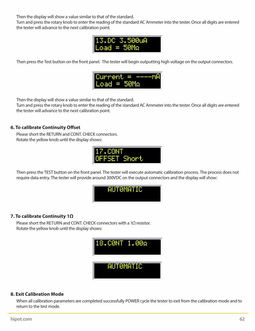
hipot.com 62
Then press the Test button on the front panel. The tester will begin outputting high voltage on the output connectors.
Then the display will show a value similar to that of the standard. Turn and press the rotary knob to enter the reading of the standard AC Ammeter into the tester. Once all digits are entered
the tester will advance to the next calibration point.
6. To calibrate Continuity Offset Please short the RETURN and CONT. CHECK connectors. Rotate the yellow knob until the display shows:
Then press the TEST button on the front panel. The tester will execute automatic calibration process. The process does not require data entry. The tester will provide around 300VDC on the output connectors and the display will show:
7. To calibrate Continuity 1Ω Please short the RETURN and CONT. CHECK connectors with a 1Ω resistor. Rotate the yellow knob until the display shows:
8. Exit Calibration Mode When all calibration parameters are completed successfully POWER cycle the tester to exit from the calibration mode and to
return to the test mode.
Then the display will show a value similar to that of the standard. Turn and press the rotary knob to enter the reading of the standard AC Ammeter into the tester. Once all digits are entered
the tester will advance to the next calibration point.