
OPERATING MANUAL - Dimplex Thermal · The P030 Chiller described in this manual is designed for...
44
Original 454522.68.07-01-E 12.02.0032 OPERATING MANUAL P030 Chiller Glen Dimplex Deutschland GmbH Geschäftsbereich RIEDEL Kältetechnik Am Goldenen Feld 18 D-95326 Kulmbach Phone: +49 (0) 9221 / 709 555 Fax: +49 (0) 9221 / 709 549 HEADQUARTERS GERMANY Phone: +49 (0) 9221 / 709 545 Fax: +49 (0) 9221 / 709 529 e-mail: [email protected] http://www.Riedel-Cooling.com PARTS & SERVICE HOTLINE NORTH AMERICA Phone: ++1-877 RIEDEL1 Phone: ++1-877 -743 -3351 Fax: ++1-734 -595 -9829 e-mail: [email protected] http://www.riedel-usa.com
Transcript of OPERATING MANUAL - Dimplex Thermal · The P030 Chiller described in this manual is designed for...

Original
454522.68.07-01-E
12.02.0032
OPERATING MANUAL
P030 Chiller
Glen Dimplex Deutschland GmbH
Geschäftsbereich RIEDEL Kältetechnik Am Goldenen Feld 18
D-95326 Kulmbach
Phone: +49 (0) 9221 / 709 555 Fax: +49 (0) 9221 / 709 549
HEADQUARTERS GERMANY Phone: +49 (0) 9221 / 709 545 Fax: +49 (0) 9221 / 709 529
e-mail: [email protected] http://www.Riedel-Cooling.com
PARTS & SERVICE
HOTLINE
NORTH AMERICA Phone: ++1-877 RIEDEL1
Phone: ++1-877 -743 -3351 Fax: ++1-734 -595 -9829
e-mail: [email protected] http://www.riedel-usa.com

ENGLISH Translation of the Original
2 454522.68.07-01-E
27.06.2012
This document was drawn up by the Technical Documentation Dept. of Glen Dimplex Deutschland GmbH. Glen Dimplex reserves all rights to this documentation, especially the right to reproduce, distribute and translate this document. This also applies with respect to application for patents and industrial rights. No part of this document may be reproduced, processed, copied or distributed by either conventional or electronic means without the prior written consent of Glen Dimplex. Subject to errors and technical changes. Glen Dimplex assumes no responsibility for any errors in this documentation. To the extent permissibly by law, Glen Dimplex will not be liable for any warranty claims for direct or indirect damages arising in connection with the supply or non-use of this documentation.
Ordering information:
Documentation order number
To be entered by the user:
Inventory number:
Installation site:

Translation of the Original ENGLISH
454522.68.07-01-E 3
27.06.2012
TABLE OF CONTENTS1 FOR YOUR SAFETY .......................................................................................................... 5
1.1 REGULATIONS...................................................................................................................................................5 1.2 SIGNS AND SYMBOLS ........................................................................................................................................6 1.3 SAFETY NOTICES ..............................................................................................................................................7 1.4 HANDLING OF REFRIGERANTS............................................................................................................................8 1.5 SAFETY REQUIREMENTS....................................................................................................................................9 1.6 PURPOSE OF THE P030 CHILLER .....................................................................................................................10 1.7 DECLARATION OF CONFORMITY .......................................................................................................................11
2 DESCRIPTION OF THE P030 CHILLER.................. ........................................................ 12
2.1 OVERVIEW P030 CHILLER ...............................................................................................................................12 2.2 REFRIGERATION CIRCUIT.................................................................................................................................12 2.3 WATER CIRCUIT..............................................................................................................................................14 2.4 COOLING AIR SUPPLY .....................................................................................................................................14 2.5 SAFETY DEVICES ............................................................................................................................................15 2.6 MONITORING DEVICES.....................................................................................................................................15 2.7 ELECTRICAL/CONTROL EQUIPMENT .................................................................................................................16
3 TECHNICAL DATA................................... ........................................................................ 17
3.1 HYDRAULIC DATA............................................................................................................................................17 3.2 ELECTRICAL DATA...........................................................................................................................................17 3.3 GENERAL DATA...............................................................................................................................................17 3.4 NAME PLATE...................................................................................................................................................18
4 TRANSPORT AND STORAGE............................ ............................................................. 19
4.1 TRANSPORT SPECIFICATION ............................................................................................................................19 4.2 TRANSPORT USING A FORKLIFT .......................................................................................................................20 4.3 TRANSPORT USING A LIFT TRUCK ....................................................................................................................21 4.4 TRANSPORT USING A CRANE ...........................................................................................................................22 4.5 STORAGE OF THE P030 CHILLER .....................................................................................................................23
5 INSTALLATION..................................... ........................................................................... 24
6 MOUNTING....................................................................................................................... 25
6.1 CONNECTION OF WATER PIPING ......................................................................................................................25 6.2 ELECTRO-TECHNICAL CONNECTION .................................................................................................................26 6.3 OPTICAL FIBRE CONNECTION ..........................................................................................................................26
7 COMMISSIONING ............................................................................................................ 28
7.1 WATER CIRCUIT..............................................................................................................................................28 7.2 INITIAL START-UP OF THE PUMP ......................................................................................................................30 7.3 REFRIGERATION CIRCUIT.................................................................................................................................30
8 DECOMMISSIONING ....................................................................................................... 31
9 SHUTDOWN IN EMERGENCIES ..................................................................................... 32
10 ENVIRONMENTAL REQUIREMENTS ...................... ....................................................... 33
11 OPERATION OF CONTROL AND OPERATING UNIT ......... ........................................... 34
11.1 CONTROL AND OPERATING UNIT ST 181..........................................................................................................34
12 MAINTENANCE..................................... ........................................................................... 36

ENGLISH Translation of the Original
4 454522.68.07-01-E
27.06.2012
12.1 REPLACING FILTER ELEMENT .......................................................................................................................... 37
13 PERIODICAL INSPECTIONS AND TESTS................ ...................................................... 38
14 MALFUNCTIONS / TROUBLESHOOTING .................. .................................................... 40
14.1 MALFUNCTIONS / TROUBLESHOOTING OF CONTROL AND OPERATING UNIT ST 181 ............................................ 40
15 OPTIONS .......................................................................................................................... 44
15.1 WATER CIRCUIT.............................................................................................................................................. 44 15.2 ELECTRICAL SYSTEM ...................................................................................................................................... 44 15.3 COOLING AIR SUPPLY ..................................................................................................................................... 44

Translation of the Original ENGLISH FOR YOUR SAFETY
454522.68.07-01-E 5
27.06.2012
1 FOR YOUR SAFETY
1.1 Regulations
Design, construction and development of the P030 Chiller are in compliance with the following national and international regulations.
EC Directives / Standards EC Machinery Directive 2006/42/EC EC EMC Directive 2004/108/EC EC Pressure Equipment Directive 97/23/EC EN 378-1:2008 + A1:2010 Refrigerating systems and heat pumps. Safety and environmental
requirements – Part 1, Basic requirements, definitions, classification and selection
EN 378-2:2008 + A1:2009 Refrigerating systems and heat pumps. Safety and environmental requirements – Part 2, Design, construction, testing, marking and documentation
EN 378-3:2008 Refrigerating systems and heat pumps. Safety and environmental requirements – Part 3, Installation site and personal protection
EN 378-4:2008 Refrigerating systems and heat pumps. Safety and environmental requirements – Part 4, Operation, maintenance, repair and recovery
EN 60529:1991 + A1:2000 Degrees of protection provided by enclosures (IP) EN 12100:2004, Parts 1 + 2 Safety of machinery – Basic concepts, general principles for design EN 13857:2008 Safety of machinery – Safety distances to prevent hazard zones
being reached by upper and lower limbs EN 349:1993 + A1:2008 Safety of machinery – Minimum gaps to avoid crushing of parts of
the human body EN 60204-1: Electrical equipment of machines – Part 1: General 2006 + A1:2009 requirements EN 61000-6-2:2005 Electromagnetic compatibility/generic immunity standard EN 61000-6-4: Electromagnetic compatibility/generic emission standard 2007 + A1:2011 EN ISO 14121-1:2007 Safety of machinery. Risk assessment – Part 1
National Directives BGR 500, Chapt. 2.35 Accident prevention regulations concerning refrigeration plants
and heat pumps
FOR YOUR SAFETY ENGLISH Translation of the Original
6 454522.68.07-01-E
27.06.2012
1.2 Signs and Symbols
Throughout this operating manual, the information and notices below are identified by the following graphical symbols:
Danger!
Safety note pointing out an imminent danger. Failure to heed the warning may result in serious bodily injury and even death.
Caution!
Safety note to indicate the presence of a potential hazard. Failure to heed the safety notice may result in minor bodily injury.
Notice!
This symbol identifies important information or a useful tip concerning the application of the equipment.

Translation of the Original ENGLISH FOR YOUR SAFETY
454522.68.07-01-E 7
27.06.2012
1.3 Safety Notices
For the installation, operation and maintenance of the P030 Chiller the following regulations and safety notices have to be observed:
Danger!
• Any work on the P030 Chiller may only be performed by qualified personnel.
• All relevant accident prevention regulations have t o be observed.
• Do not allow anybody to stand or pass underneath th e forks when lifting and setting down the P030 Chiller, stay clear of the da nger area.
• The P030 Chiller must be properly secured in order to prevent it from tipping over.
• The safety devices must not be deactivated.
• The electrotechnical connections of the P030 Chiller must be performed according to and conforming to all relevant VDE, EN and. IEC standards. Beyond that, the technical connection requirements of the local electrical utility company have to be complied with.
• Always disconnect the power supply before working o n the P030 Chiller.
Caution!
• Specific regional or national provisions applicable in the country where the unit will be installed must be adhered to.
• The closed refrigeration circuit contains refrigera nts and refrigeration oil. These must be properly disposed of when performing servic e work or placing the unit out of service (environment).
• The cooling water additives have a caustic effect o n skin and eyes. When working with cooling water additives, protective safety gog gles and gloves must be worn. Follow the directions on the product labels.
• Anyone working on the refrigeration circuit must be protected by personal protective equipment.
• The P030 Chiller is to be used exclusively for the cooling of water and water-glycol mixtures in accordance with predefined speci fications.
Notice!
• Watch out for any incompatibilities of materials in the entire water circuit.
• The water must be free of all substances that could result in mineral deposits and corrosion.

FOR YOUR SAFETY ENGLISH Translation of the Original
8 454522.68.07-01-E
27.06.2012
The water used in the cooling circuit must comply, at a minimum, with the values specified by the Ordinance on Drinking Water. In the case of de-ionised water, additional constructional features are necessary.
Based on the drinking water ordinance the following limit values are recommended:
Drinking Water Properties Appearance: clear, no sediments Colour: transparent
Ingredients Unit Value
Electric conductivity at 25 °C: µS/cm 80 -750 Hydrogen concentration at 20 °C pH value 6.5 –9.5 Chloride (max.) mg/l 250 Total hardness (min.) °dH 6 Total colony count at 22°C (max.) CFU s/ml 100
1.4 Handling of Refrigerants
Notice!
• When handling refrigerants, all legal provisions an d guidelines must be complied with. Only qualified personnel may perform these ac tivities.
The operator of the P030 Chiller is responsible for the proper disposal of used refrigerants and system parts.

Translation of the Original ENGLISH FOR YOUR SAFETY
454522.68.07-01-E 9
27.06.2012
1.5 Safety Requirements
Operation of P030 Chillers within the European Union:
The following information applies to P030 Chillers with closed refrigeration cycles that are used within the European Union. In some member states additional requirements may apply, e.g. due to environmental considerations.
The P030 Chillers contain components whose working pressures are subject to the regulations laid down in the Pressure Equipment Directive 97/23/EC and European standard EN 378 (Parts 1 − 4, most recent version).
Apart from the requirements relating to the design, equipment and testing of the P030 Chiller prior to delivery to the customer, also the operator of such systems has to comply with requirements in accordance with European standard EN 378 and possibly additional national regulations. These concern the installation, the operation and periodical inspections/tests of P030 Chillers.
1.5.1 Installation
The P030 Chiller is designed for outdoor operation. The installation altitude must not exceed 2000m above sea level. The height difference between the installation site of the P030 Chiller and the COO system separator (Siemens Magnetic Resonance Tomograph) must not exceed −30 to +10 meters.
1.5.2 Operation
The owner or operator of the P030 Chiller has the obligation to establish emergency practices (in the case of accidents and malfunctions). Based on this Operating Manual, the operator must draw up a short version of the operating instructions (quick reference guide) and make it available to the employees.
Notice!
• The quick reference guide must be clearly legible a nd affixed in the immediate vicinity of the P030 Chiller.
(See Sample Quick Reference Guide)
• The owner or operator has the obligation to keep a logbook for the P030 Chiller.
he system logbook must either be available on site near the P030 Chiller, or in the event that the data are stored in a computer of the owner or operator, a printout of the log must be kept in the vicinity of the P030 Chiller. It must be ensured that these data are accessible to qualified persons for the performance of repairs and periodical inspections/tests.
1.5.3 Periodical Inspections/Tests
To ensure compliance with minimum safety and health requirements as set forth in standard EN 378, regular tests and inspections of the P030 Chiller are to be carried out by competent persons.
Notice!
• The operator of the unit is responsible for the per formance of periodical inspections and tests.
(See Chapter Periodical Inspections/Tests).

FOR YOUR SAFETY ENGLISH Translation of the Original
10 454522.68.07-01-E
27.06.2012
1.6 Purpose of the P030 Chiller
The P030 Chiller described in this manual is designed for outdoor use and is intended exclusively for the cooling of water, or a water-glycol mixture (ratio 60: 40%), for the system separator (COO of the P030 Chiller).
The system separator supplies the connected components (equipment to be cooled) with cooling water maintaining its temperature at a constant level. It may only be operated in conjunction with the specified devices.
Notice!
• No changes are allowed to be made to the P030 Chill er.
• The P030 Chiller must not be operated or used in co njunction with other than the specified components and devices.

Translation of the Original ENGLISH FOR YOUR SAFETY
454522.68.07-01-E 11
27.06.2012
1.7 Declaration of Conformity

DESCRIPTION OF THE P030 CHILLER ENGLISH Translation of the Original
12 454522.68.07-01-E
27.06.2012
2 DESCRIPTION OF THE P030 CHILLER The P030 Chiller is a unit ready for plug-in and is equipped with a refrigeration and water circuit including all fittings and regulating/control devices required for automatic operation. The heat extracted from the water is given off to the ambient air by means of the refrigeration circuit via the condenser and the fans.
2.1 Overview P030 Chiller
View of an open chiller
1. Pressure vessel 2. Fan 3. Condenser 4. Expansion tank 5. Evaporator 6. Compressor 7. Control cabinet 8. Control switch 9. Main switch
10. Vent
11. Pump
2.2 Refrigeration Circuit
The refrigeration circuit is a closed-loop system in which the refrigerant R134 circulates as the heat transfer medium.
The water heated by the system separator is recooled in the evaporator (4). The liquid refrigerant is thereby passed through the piping in a counter-flow arrangement with respect to the water. The refrigerant evaporates as it takes up the waste heat from the cooling water of the system separator.

Translation of the Original ENGLISH DESCRIPTION OF THE P030 CHILLER
454522.68.07-01-E 13
27.06.2012
The vaporised refrigerant is drawn in by the three compressors (1) and is then compressed (rise in pressure and temperature). The refrigerant also absorbs the heat of the compressor motor, and this heat is given off to the surrounding air by the condenser (2) – in the form of waste heat – by means of the two fans (3).
The refrigerant is thus liquefied and passed to the inlet of the expansion valve (5) via the liquid receiver (pipe expansion), the filter drier (7) and the sight glass (6). The expansion valve permits liquid refrigerant to enter the evaporator as a function of the temperature.
Block flow diagram, Refrigeration Circuit
1. Compressor 2. Condenser 3. Fan 4. Evaporator 5. Expansion valve 6. Sight glass 7. Filter drier 8. Pipe expansion (receiver) 9. Hot gas bypass valve

DESCRIPTION OF THE P030 CHILLER ENGLISH Translation of the Original
14 454522.68.07-01-E
27.06.2012
2.3 Water Circuit
The water circuit of the P030 Chiller together with the connecting hoses constitutes the transport system of the cooling water between the P030 Chiller and the primary circuit of the system separator (COO). This closed water circuit is designed in accordance with requirements and is equipped with all fittings and components required for safety and monitoring purposes. The water circuit is provided with its own pump.
2.4 Cooling Air Supply
The heat transferred to the evaporator upon cooling the water as well as the heat generated by the compressor motors are absorbed by the refrigerant and given off to the cooling air in the condenser. As cooling air the ambient air is used which is drawn through the condenser by the fans; the air is warmed in the process and then discharged in upward direction.
Caution!
• It must be ensured that the cooling air can be draw n in and discharged without any obstruction and adequate air changes for heat d issipation away from the installation site of the chiller can take place.

Translation of the Original ENGLISH DESCRIPTION OF THE P030 CHILLER
454522.68.07-01-E 15
27.06.2012
2.5 Safety Devices
The P030 Chiller is equipped with the following safety devices:
High-pressure control (HP)
The high-pressure control is designed to protect the P030 Chiller against extremely high operating pressure in the refrigeration circuit. In the event of a malfunction, the HP control switches the P030 Chiller off and the malfunction is indicated on the control panel of the control and operating unit. The P030 Chillers cannot be restarted until the pressure has dropped to the preset pressure difference and the Reset button on the high-pressure pressostat has been pressed. The pressostat is accessible from the service side.
Power disconnect switch (main switch)
In an emergency, the P030 Chiller must be switched off by means of the main switch.
2.6 Monitoring Devices
Low-pressure control (LP)
The low-pressure control protects the P030 Chiller against extremely low operating pressure in the refrigeration circuit. In the event of a malfunction, the control switches off the P030 Chiller, and the malfunction is indicated on the control and operating unit. Restarting of the P030 Chiller is effected automatically as soon as the pressure has risen by the preset pressure difference.
Compressor overheat protection
Each compressor is equipped with an overheat protection (thermal contact, Klixon). In the event of an increase in motor current in conjunction with a rise in the winding temperature, the overheat protection trips, and the compressor is switched off. The overheat protection resets itself automatically after the windings have cooled down. This malfunction is not indicated on the control and operating unit.
Thermal contact – fan motor
In the event of an increase in motor current in conjunction with an increase in winding temperature, cooling operation is switched off by the thermal contact. This malfunction is indicated on the control and operating unit.
Circuit breakers (compressor, fan, pump)
In the event of an increase in motor current or in the case of short circuits, the circuit breaker trips and interrupts the power supply. Such malfunctions are indicated on the control panel. The circuit breakers are located in the control cabinet.
Flow and pressure switches in the water circuit
The flow switch shuts off the pump when the preset volume flow limit value is fallen short off and sends a corresponding signal to the control and operating unit.
The pressure switch does not signal the malfunction to the control and operating unit if a pressure increase in the water circuit exceeds the preset value.
Fan control
The condensation pressure is controlled by cycling the individual fans on and off. This type of control permits an adaptation to different operating conditions at relatively constant condensation temperatures.

DESCRIPTION OF THE P030 CHILLER ENGLISH Translation of the Original
16 454522.68.07-01-E
27.06.2012
Control and operating unit
The control and operating unit controls the water circuits and the refrigeration circuit. The control and operating unit with display of the water temperature as well as the error codes in the case of a general fault alarm is integrated in the control cabinet door.
2.7 Electrical/Control Equipment
The electro-technical equipment of the P030 Chiller is installed in the control cabinet. All required components for the automatic switching, controlling and regulating operation are contained in the control cabinet.
The main electric circuits are of a non-fused design featuring motor protecting switches.
The water outlet temperature is kept constant by the control and operating unit at a given setpoint value by activation of power stages in the refrigeration circuit. The current water outlet temperature is displayed on the control and operating unit.
The connection of the P030 Chiller to the equipment to be cooled is effected via a potential-free interface. To achieve a galvanic isolation of the equipment to be cooled and the P030 Chiller, the connection is accomplished by means of optical-fibre cables.

Translation of the Original ENGLISH TECHNICAL DATA
454522.68.07-01-E 17
27.06.2012
3 TECHNICAL DATA
3.1 Hydraulic Data Description Unit Values
Designation: P030 Chiller Type 2NK6 772 C Cooling capacity kW 37 Cooling medium, primary circuit
water/glycol mixture 60 %/40 %
Cooling medium outlet temperature
°C 9 ± 3 K
Operation volume flow, cooling medium
m3/h 3
Max. operating pressure (against closed valve) bar
3.8 at 50 Hz 5.4 at 60 Hz
Max. allowable pressure (cooling medium circuit)
bar 10
3.2 Electrical Data Values
Description Unit 50 Hz 60 Hz
Operating voltage V/Ph/Hz 400/3/50 460/3/60 Power input, overall system
kW 28 34
Max. current draw A 50 54 Fuse protection at site A max. 63 max. 63
3.3 General Data Description Unit Values
Connections mm M36 x 2 / DN 25 Dimensions W x H x D mm 1640 x 1953 x 841 Weight kg 606

TECHNICAL DATA ENGLISH Translation of the Original
18 454522.68.07-01-E
27.06.2012
3.4 Name Plate
Name Plate
3.4.1 Installation Location of the Type Plate
The name plate is attached to the front of the control cabinet, at the bottom on the right.
Location of the name plate and the barcode identification label
Barcode identification label
Name plate
Translation of the Original ENGLISH TRANSPORT AND STORAGE
454522.68.07-01-E 19
27.06.2012
4 TRANSPORT AND STORAGE
Caution!
• The safety notices contained in Chapter 1 must be c omplied with! As a rule, the P030 Chiller must be transported in upright positio n without water charge!
• Stacking the units may result in serious accidents and damage to the units and is, on principle, not permitted!
• Damaged units must be sorted out immediately!
The in-house transport is carried out by a forklift, lift truck or crane. The P030 Chiller must be deposited on a level surface to prevent any distortion of the base-frame.
4.1 Transport Specification − Weight (see Chapter Technical Data) − Main dimensions (see Chapter Technical Data) − Ambient temperature range: –20°C to +60°C at a rel ative humidity of 10 to 90 %.
In ambient temperatures <0°C the water circuits mus t be completely drained, including pumps and pressure vessel. (See Chapter Decommissioning)

TRANSPORT AND STORAGE ENGLISH Translation of the Original
20 454522.68.07-01-E
27.06.2012
4.2 Transport Using a Forklift
To move the P030 Chiller with a fork lift, the recesses provided at the broadside of the base-frame of the unit should exclusively be used. Do not lift the unit until the forks have been inserted horizontally all the way beneath the unit, symmetrically to the centre of gravity of the P030 Chiller.
Recesses, Transport with Forklift
Caution!
• The lifting rate should be kept to a minimum!
Translation of the Original ENGLISH TRANSPORT AND STORAGE
454522.68.07-01-E 21
27.06.2012
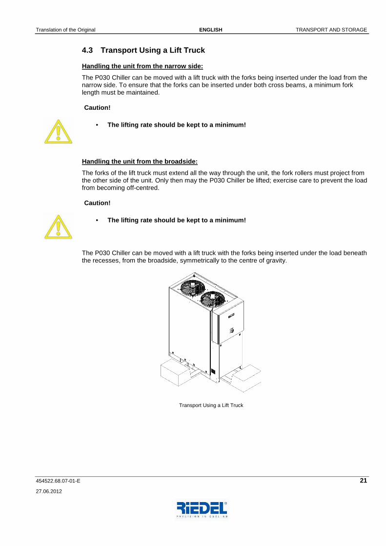
4.3 Transport Using a Lift Truck
Handling the unit from the narrow side:
The P030 Chiller can be moved with a lift truck with the forks being inserted under the load from the narrow side. To ensure that the forks can be inserted under both cross beams, a minimum fork length must be maintained.
Caution!
• The lifting rate should be kept to a minimum!
Handling the unit from the broadside:
The forks of the lift truck must extend all the way through the unit, the fork rollers must project from the other side of the unit. Only then may the P030 Chiller be lifted; exercise care to prevent the load from becoming off-centred.
Caution!
• The lifting rate should be kept to a minimum!
The P030 Chiller can be moved with a lift truck with the forks being inserted under the load beneath the recesses, from the broadside, symmetrically to the centre of gravity.
Transport Using a Lift Truck

TRANSPORT AND STORAGE ENGLISH Translation of the Original
22 454522.68.07-01-E
27.06.2012
4.4 Transport Using a Crane
For the transport of the P030 Chiller, lifting eyes are provided in the upper frame enabling a 4-leg sling load arrangement.
Load suspension devices
Wire rope slings (lifting rope assemblies) according to DIN 3088, or sling chains (lifting chain assemblies) according to DIN 5687/ 5688. Both load suspending devices comply with the requirement of a sling with equal rope or chain lengths to be used.
Rope inclination angle
Ensure that the rope inclination angle as shown in the illustration is complied with.
Lifting rate
Keep lifting rate to a minimum (VLift <10m/min – precision lifting, jerk-free lifting operation)
Depositing the P030 Chiller
To prevent any distortions of the lower frame from occurring, the P030 Chiller must be lowered onto a level surface.
Transport Using a Crane

Translation of the Original ENGLISH TRANSPORT AND STORAGE
454522.68.07-01-E 23
27.06.2012
4.5 Storage of the P030 Chiller
The P030 Chiller must be stored on a level surface, or supported on additional square beams, in a dry room, protected from frost. Permissible storage temperature range: −20°C to 60°C.
For storage in ambient temperatures below 0°C, it i s imperative that decommissioning measures be taken. (See Chapter Decommissioning)
Caution!
• It is, on principle, not allowed to stack the appli ances. Stacking may lead to serious accidents and damage to the units.

INSTALLATION ENGLISH Translation of the Original
24 454522.68.07-01-E
27.06.2012
5 INSTALLATION
Caution!
• The safety notices contained in Chapter 1 must be c omplied with!
• In low storage temperatures (< 10 °C) allow for an appropriate acclimatisation period before turning the unit on!
• Transport packaging to be removed before turning th e unit on!
Installation of the P030 Chiller
The P030 Chiller is to be installed outdoors on a level, horizontal surface with adequate load bearing capability. Any attachments to the floor, intermediate spacers or anti-vibration mountings are not required. Any national or local installation and mounting regulations must be complied with!
For different installation conditions, consult the manufacturer.
Notice!
• To ensure trouble-free operation of the P030 Chille r as well as to provide adequate access for the performance of maintenance and repair work, minimum clearances must be maintained when installing the u nit. (See also Dimensions)
• These installation requirements ensure that the coo ling air can be drawn in and discharged without obstructions. It can thus be lar gely prevented that the air discharged in upward direction is reintroduced into the chiller (air short-circuiting).
• Moreover, adequate air changes for heat dissipation at the installation site must be ensured.

Translation of the Original ENGLISH MOUNTING
454522.68.07-01-E 25
27.06.2012
6 MOUNTING Caution!
• The safety notices contained in Chapter 1 must be c omplied with!
6.1 Connection of Water Piping
The hydraulic connections are located at the bottom on the left side of the unit The nominal pipe widths and fitting connections are intended for use of the original hose set and/or the "Active hose set".
In the case of differing connection conditions, all applicable technical data have to be submitted to Glen Dimplex Deutschland GmbH in order to obtain from them a written special approval prior to commissioning. To avoid any damage, the corrosion behaviour of the materials (used in the equipment to be cooled) with respect to the water must be taken into consideration (see also the Chapter Commissioning).
Connection of Water Piping
Notice!
• Where the piping system is installed at the install ation site by the customer, care must be taken that the pipe system is free from con tamination (lines may have to be flushed prior to connecting the P030 Chiller).
MOUNTING ENGLISH Translation of the Original
26 454522.68.07-01-E
27.06.2012
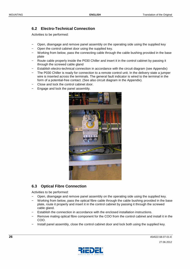
6.2 Electro-Technical Connection
Activities to be performed:
− Open, disengage and remove panel assembly on the operating side using the supplied key − Open the control cabinet door using the supplied key. − Working from below, pass the connecting cable through the cable bushing provided in the base
plate − Route cable properly inside the P030 Chiller and insert it in the control cabinet by passing it
through the screwed cable gland − Establish electro-technical connection in accordance with the circuit diagram (see Appendix) − The P030 Chiller is ready for connection to a remote control unit. In the delivery state a jumper
wire is inserted across the terminals. The general fault indicator is wired to the terminal in the form of a potential-free contact. (See also circuit diagram in the Appendix).
− Close and lock the control cabinet door. − Engage and lock the panel assembly.
6.3 Optical Fibre Connection
Activities to be performed: − Open, disengage and remove panel assembly on the operating side using the supplied key. − Working from below, pass the optical fibre cable through the cable bushing provided in the base
plate, route it properly and insert it in the control cabinet by passing it through the screwed cable gland.
− Establish the connection in accordance with the enclosed installation instructions. − Remove mating optical fibre component for the COO from the control cabinet and install it in the
COO. − Install panel assembly, close the control cabinet door and lock both using the supplied key.

Translation of the Original ENGLISH MOUNTING
454522.68.07-01-E 27
27.06.2012
Installation instructions for optical fibre cable

COMMISSIONING ENGLISH Translation of the Original
28 454522.68.07-01-E
27.06.2012
7 COMMISSIONING
Caution!
• The safety notices contained in Chapter 1 must be c omplied with!
• The P030 Chiller is designed exclusively for the co oling of water. Only liquids complying with the specification may be used for fi lling the water circuits!
7.1 Water Circuit
7.1.1 Water Requirements
Only water of drinking water quality, at a minimum, see drinking water properties (page 8) – or a water-glycol mixture in a ratio of 60:40% may be used.
The following materials may be installed in the water circuit of the P030 Chiller: − Copper − Stainless steel − Brass − Red bronze − Plastic
Depending on the materials used in the chiller-remote water circuit (installation to be provided by the customer) material incompatibilities could result in a corrosion hazard. This must especially be taken into account where galvanised and aluminium materials are used. If in doubt, consult competent specialist contractors.
7.1.2 Flushing, Filling and Venting
Notice!
• Due to the fact that the P030 Chiller and its downs tream equipment to be cooled can be installed at different levels, it must be en sured that the system is properly filled and vented.

Translation of the Original ENGLISH COMMISSIONING
454522.68.07-01-E 29
27.06.2012
Step Action
01 Connect the Filler device to the K-F-E valve [3] at the pump. Use a transparent hose for connecting it to the K-F-E valve [4]. Put the open end of that hose into a pan or canister.
ATTENTION: Do not drain Glycol or Glycol mixtures into the sewage drain!
02 Open only the K-F-E valve [3] at the pump, all others have to be closed.
03 Close the ballvalves in the main branch [1 & 2].
04 Switch on the Filler device air bleeder [6] on the tank [5] is venting.
05 After finishing the venting process, open valve [2] and also K-F-E valve [4].
06 After escaping only pure cooling medium (without air bubbles) out of K-F-E valve [4], close this valve and open ball valve [1].
07 Fill the cooling circuit up to a pressure of about 1.7 to 2bar (see pressure gauge [8]). While you´re doing this, air bleeder [7] is venting.
08
After venting is finished, close K-F-E valve [3] at the pump. The pressure shown at the pressure gauge [8] should stay stable for at least 10 minutes. If the pressure reduces, start again at step 05 and repeat as long as the pressure is stable.
ATTENTION: Check the system for leakage at this step!
6
5
1
2
4
3 7
8

COMMISSIONING ENGLISH Translation of the Original
30 454522.68.07-01-E
27.06.2012
7.2 Initial Start-Up of the Pump
Danger!
• Always disconnect the power supply before working o n the P030 Chiller.
• All control switches, motor protecting switches and automatic circuit breakers must be placed to the "0" position!
The pump motor is equipped with a rotation direction sensor whose position can be changed.
Notice!
• A functional check of the rotation direction sensor should be carried out
before the initial start-up of the pump motor
whenever the position of the rotation direction sen sor has been changed.
The functional check can be carried out by moving the rotation direction sensor, e.g. with your finger.
To determine the direction of rotation of the pump motor, proceed as follows: − Complete the procedure "flushing, filling and venting" as described in Chapter 7.1.2. − Establish the electrical connections in accordance with Chapters 6.2 and 6.3. − Switch on the pump. − Observe the small display window in the rotation direction sensor.
The rotation direction is correct if a black area appears in the window, no further activities are required.
In the event that a white area appears in the window, the following steps must be performed: − Disconnect the P030 Chiller from the power supply, place all switches and automatic circuit
breakers to the "0" position. − Reverse any two of the three electrical leads (phases). − Re-check the rotation direction of the pump motor, as described above.
7.3 Refrigeration Circuit
After the activities on the water circuit and the pump have been completed, place the motor protecting switches of the compressors to the -1- position (see circuit diagram in the Appendix). Clear all pending fault messages at the control and operating unit. The P030 Chiller is ready for operation and the control and operating unit takes over the control of the water outlet temperature.
Notice!
• Check the setpoint adjustment and change the settin g, if necessary.

Translation of the Original ENGLISH DECOMMISSIONING
454522.68.07-01-E 31
27.06.2012
8 DECOMMISSIONING
Caution!
• The safety notices contained in Chapter 1 must be c omplied with!
If the P030 Chiller is not used for an extended period or if it is to be disassembled, the unit has to be taken out of service.
The following procedure should be followed: − Control switch (at the front of the unit) in position "0" − Main switch (at the front of the unit) in position "0" − Switch off the power to the chiller − Completely drain the water circuit, including tank, pump, pipes and filters (see flow diagram in
the Appendix).
Notice!
• Take freeze protection measures (consult manufactur er)

SHUTDOWN IN EMERGENCIES ENGLISH Translation of the Original
32 454522.68.07-01-E
27.06.2012
9 SHUTDOWN IN EMERGENCIES Danger!
• The safety notices contained in Chapter 1 must be c omplied with!
− Turn power disconnect switch (main switch) on the control cabinet of the P030 Chiller to the "OFF" position − „0“ −.
Main switch in "0" position

Translation of the Original ENGLISH ENVIRONMENTAL REQUIREMENTS
454522.68.07-01-E 33
27.06.2012
10 ENVIRONMENTAL REQUIREMENTS When repairing or placing the P030 Chiller out of service (decommissioning), the environment-relevant requirements regarding recovery, reuse and disposal of fuels/oils and components according to DIN EN 378 are to be complied with.
Notice!
• The operator of the P030 Chiller is responsible for the proper disposal of used fuels, oils and system components.
The disposal of the water containing additives is to be effected in agreement with the competent local authorities.

OPERATION OF CONTROL AND OPERATING UNIT ENGLISH Translation of the Original
34 454522.68.07-01-E
27.06.2012
11 OPERATION OF CONTROL AND OPERATING UNIT The P030 Chiller is switched on by means of power disconnect switch (main switch) which also doubles as an EMERGENCY STOP switch. The P030 Chiller is now ready for operation, and control and operating unit takes over the control of the water outlet temperature. It is not possible to start up the unit for as long as there is an active low water level or dry run protection signal.
11.1 Control and Operating Unit ST 181
No. Function No. Function
1 Display 7 SET call-up of setpoint S1 (compressor control) S2 (not used)
2 Alarm status displays General fault alarm Temperature alarm Low water level Pump Refrigeration fault High pressure HP Low pressure LP
9 HP/LP button Reading of HP sensor -> HP/LP button pressed Reading of LP sensor -> HP/LP + DOWN button pressed 3 Control modes
1 Control setting 1 On 2 Control setting 2 On 3 Control setting 3 On
4 UP button to increase setpoint or parameter value
5 DOWN button to decrease setpoint or parameter value
10 No function
6 Buzzer button Press 1x: buzzer off Press 2x: alarm reset
11 No function
Control and Operating Unit ST 181
Actual values

Translation of the Original ENGLISH OPERATION OF CONTROL AND OPERATING UNIT
454522.68.07-01-E 35
27.06.2012
In the normal state, the flow temperature of the water circuit is indicated on the display.
Setpoint adjustment
The setpoint is adjusted by simultaneously pressing the SET button and the UP or DOWN button.

MAINTENANCE ENGLISH Translation of the Original
36 454522.68.07-01-E
27.06.2012
12 MAINTENANCE
Caution!
• The safety notices contained in Chapter 1 must be c omplied with!
• Always disconnect the the P030 Chiller from the pow er supply before attempting to open the cabinet!
No specific refrigeration technology knowledge is required for the performance of maintenance activities. This work can be carried out by a properly trained person with appropriate know-how.
Component to be serviced
Interval Activity
P030 Chiller in general
2 weeks - Visual inspection of the air filter element for contamina-tion - Visual inspection of refrigeration circuit for leaks - In the case of oil leaks call customer service: Phone:+49 (0) 9221 / 709-545 Fax: +49 (0) 9221 / 709-529
Water circuit cooling water
2 weeks - Visual inspection of the water circuit for leaks - Check water level, top up - Observe filling pressure (pressure gauge and diaphragm expansion vessel) - Check water quality
Cooling air circuit Filter element Condenser
1 week Replace or clean filter element Clean condenser with com-pressed air, do not damage fins

Translation of the Original ENGLISH MAINTENANCE
454522.68.07-01-E 37
27.06.2012
12.1 Replacing Filter Element
The filter element can be replaced without any tools. Proceed as follows: − Pull at the lower edge of the protective grille until it can be removed from the magnetic fixing
points. − Disengage the protective grille at the top. − Remove the filter element fixed in place by velcro fastener. − The installation of a new filter element is performed in the reverse order of sequence.
View of the chiller from the left as well as a detailed view with protective grille and filter element removed.

PERIODICAL INSPECTIONS AND TESTS ENGLISH Translation of the Original
38 454522.68.07-01-E
27.06.2012
13 PERIODICAL INSPECTIONS AND TESTS
Caution
• The safety notices contained in Chapter 1 must be c omplied with!
• Always disconnect the P030 Chiller from the power s upply before attempting to open the cabinet!
During the lifetime of the P030 Chiller, inspections and tests (not included in the scope of the warranty) must be carried out in accordance with national regulations! If there are no local regulations relating to periodical inspections, regular device-specific tests have to be performed based on EN 378-2.
Scope of tests
Monitoring Test Test designation
Visual inspection
Pressure test Refrigerant leak detection
Function HP pressostat
M1 X X X X
M2 X X X
M3 X X
M4 X X1) X
Monitoring and testing must be carried out by competent personnel (in accordance with EN13313) or a specialist enterprise in compliance with environmental requirements with respect to the reuse and disposal of fuels/oils and component parts.
Definition of Test Designations
M1 Inspections/tests must be carried out following any intervention in the refrigeration
circuit due to required repair or service activities (replacement of components, elimination of leaks, replacement of filter-drier cartridges).
M2 Inspections/tests must be carried out prior to recommissioning a P030 Chiller following an extended shutdown period.
M3 Inspections/tests must be carried out whenever – after the initial startup of the P030 Chiller at the end user's site – the unit is moved to a new location. Due to special transport safety measures, any relocation of the P030 Chiller from the manufacturer's plant to the end user does not statistically result in any increased failure rate and therefore requires no re-inspection to be carried.
M4 A refrigerant charge of 11 kg requires a periodical check to be carried out once a year.

Translation of the Original ENGLISH PERIODICAL INSPECTIONS AND TESTS
454522.68.07-01-E 39
27.06.2012
The visual inspection comprises the following: − Inspection of the air filter elements on the condenser for cleanliness − Inspection of the seal of the expansion valve − Visual inspection of the refrigeration circuit for oil leaks in the area of the compressor and
condenser connecting lines (suction line, pressure line) − Inspection of the condenser heat exchanger surface and the refrigerant piping for corrosion
damage − Inspection of the mounting and attachment of all piping and components for security − Visual inspection of the water circuits under operating conditions for leaks − Check that the operating manual is available at the P030 Chiller
Notice!
• All periodical inspections and tests must be docume nted in the system logbook.

MALFUNCTIONS / TROUBLESHOOTING ENGLISH Translation of the Original
40 454522.68.07-01-E
27.06.2012
14 MALFUNCTIONS / TROUBLESHOOTING
Caution!
• The safety notices contained in Chapter 1 must be c omplied with!
The basis for troubleshooting are the circuit diagram, the flow diagram and the messages displayed on the control panel. The controlled variable is the main setpoint.
Displays on the Control and Operating Unit
See Chapter Operation of the Control and Operating Unit.
14.1 Malfunctions / Troubleshooting of Control and Operating Unit ST 181
Fault display in the event of a malfunction:
F1 -F23 will flash in alternation with the display of the actual value.
Acknowledging/resetting alarm messages on the contr ol panel
After the fault has been eliminated, reset this alarm message by pressing the (buzzer) button: − Press 1x (buzzer off) − Press 2x (buzzer and fault RESET)
Fault Display Malfunction / Cause Remedy
F1
Motor fault, pump Motor protecting switch has tripped - Pump motor overloading due to mechanical sluggishness
Check pump, replace if necessary Place motor protecting switch in position-1-
Motor fault, compressor Motor protecting switch has tripped - Compressor motor overloading due to mechanical sluggishness
Check compressor, replace if necessary. Place motor protecting switch in position -1-
F2
- Motor overloading due to phase failure
Correct phase failure. Place motor protecting switch in position -1-
Motor fault, condenser fan Motor protecting switch or thermal contact has tripped - Fan motor overloading due to mechanical sluggishness
Check fan, replace if necessary. Place motor protecting switch in position -1-
- Motor overloading due to phase failure Correct phase failure. Place motor protecting switch in position -1-
F3
- Thermal contact of a fan has tripped, motor winding overheated
Check thermal contact for continuity, allow motor to cool, replace if necessary; move motor protecting switch in position -1-
Fault Display Malfunction / Cause Remedy

Translation of the Original ENGLISH MALFUNCTIONS / TROUBLESHOOTING
454522.68.07-01-E 41
27.06.2012
Fault due to high pressure - High-pressure pressostat has tripped - Cooling air temperature too high
Ensure proper heat dissipation by increased air changes at the installation site
- Fans fail to rotate - Check fans for proper operation - Condenser or filter element dirty Clean condenser with compressed
air (do not damage fins) or replace filter element
- Water temperature too high Drain water and replace with fresh water
- Load consumption too high Reduce load consumption or shut off
F4
After a malfunction due to excessively high pressure, the pressostat must be reset manually so that the P030 Chiller can be restarted. The compressors and fans will be enabled after a delay of 180 seconds.
Fault due to high-pressure limiter - Sensor has tripped - Cooling air temperature too high
Ensure proper heat dissipation by increased air changes at the installation site
- Fans fail to rotate Check fans for proper operation - Condenser or filter element dirty Clean condenser with compressed
air (do not damage fins) or replace filter element
- Water temperature too high Drain water and replace with fresh water
- Load consumption too high Reduce load consumption or shut off - Panel assemblies not mounted on unit
Mount panel assemblies
F5
After a malfunction due to excessively high pressure, the pressure limiter must be reset manually so that the P030 Chiller can be restarted. The compressors and fans will be enabled after a delay of 180 seconds.
MALFUNCTIONS / TROUBLESHOOTING ENGLISH Translation of the Original
42 454522.68.07-01-E
27.06.2012
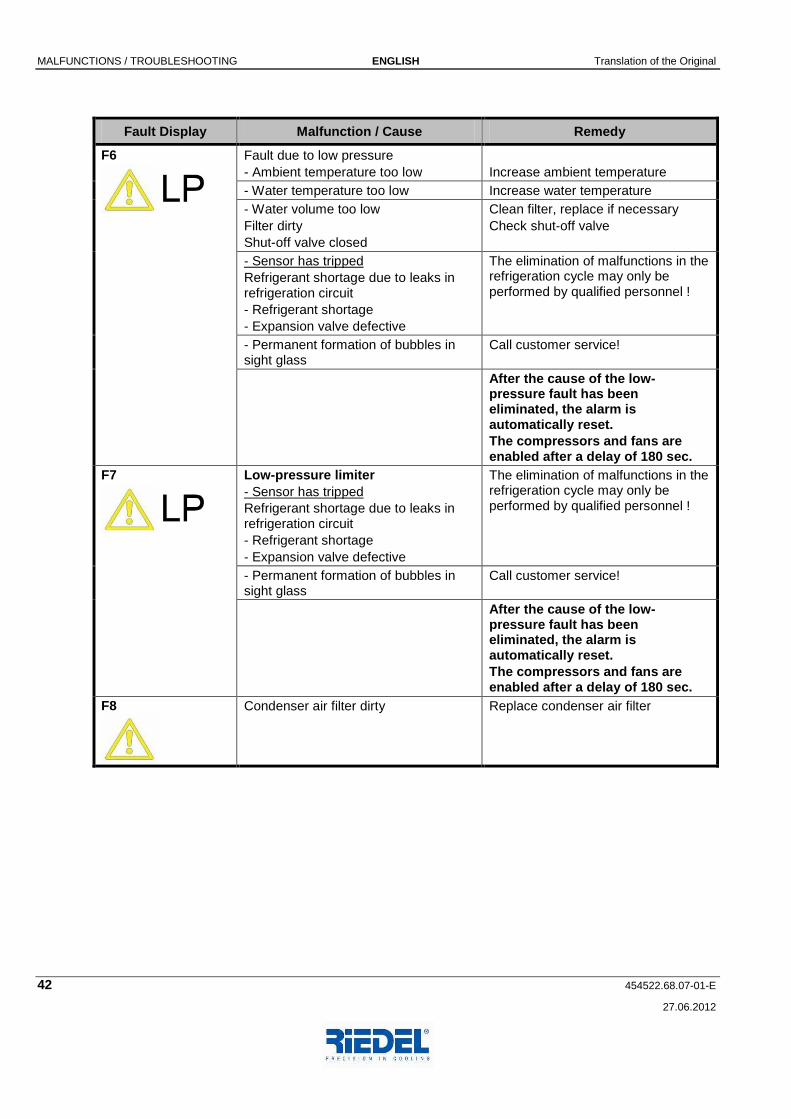
Fault Display Malfunction / Cause Remedy
Fault due to low pressure - Ambient temperature too low
Increase ambient temperature
- Water temperature too low Increase water temperature - Water volume too low Filter dirty Shut-off valve closed
Clean filter, replace if necessary Check shut-off valve
- Sensor has tripped Refrigerant shortage due to leaks in refrigeration circuit - Refrigerant shortage - Expansion valve defective
The elimination of malfunctions in the refrigeration cycle may only be performed by qualified personnel !
- Permanent formation of bubbles in sight glass
Call customer service!
F6
After the cause of the low-pressure fault has been eliminated, the alarm is automatically reset. The compressors and fans are enabled after a delay of 180 sec.
Low-pressure limiter - Sensor has tripped Refrigerant shortage due to leaks in refrigeration circuit - Refrigerant shortage - Expansion valve defective
The elimination of malfunctions in the refrigeration cycle may only be performed by qualified personnel !
- Permanent formation of bubbles in sight glass
Call customer service!
F7
After the cause of the low-pressure fault has been eliminated, the alarm is automatically reset. The compressors and fans are enabled after a delay of 180 sec.
F8
Condenser air filter dirty
Replace condenser air filter

Translation of the Original ENGLISH MALFUNCTIONS / TROUBLESHOOTING
454522.68.07-01-E 43
27.06.2012
Fault Display Malfunction / Cause Remedy
F10
Fault message Digital Fault input E7
Check filling pressure
Flow control switch has tripped - Leaks in water circuit
Check water circuit for leaks, top up water up to the MAX. mark
- Pump defective Check pump, replace if necessary Move motor protecting switch to position 1-
- Flow control switch defective Check flow control switch, replace if necessary
- Shut-off valve closed Check all shut-off valves
F11
- Water pressure too low Increase water pressure F12 Sensor F4
Temperature alarm Temperature limit values exceeded - Water temperature too high
Allow water to cool. or replace sensor, correct/reset any additional malfunctions that may be signalled
F13 Sensor F4
Temperature alarm Temperature limit values exceeded - Water temperature too low
Increase water temperature, correct/reset any additional malfunctions that may be signalled
F19 Sensor F2
Broken sensor or short circuit - Defective sensor
Check sensor, replace if necessary
F20 Sensor F3
Broken sensor or short circuit - Defective sensor
Check sensor, replace if necessary
F21 Fühler F4
Broken sensor or short circuit - Defective sensor
Check sensor, replace if necessary
F23
Eeprom error During operation, parameters are permanently checked in the controller for consistency.
Any error in this memory is indicated by a general fault alarm. Although the controller continues to operate, it must be replaced without delay.

OPTIONS ENGLISH Translation of the Original
44 454522.68.07-01-E
27.06.2012
15 OPTIONS
15.1 Water Circuit
Strainer
The strainer is included in the hose set and fitted outside the chiller in the water inlet line.
Temperature sensor
The temperature sensor detects the water inlet temperature which is displayed at the control and operating unit.
Temperature limit values
The water temperatures in the water circuit are monitored by limit values. If the preset limit values are exceeded or not reached, a general fault alarm is issued on the control panel.
Flow control switch
The flow control switch is fitted in the water inlet pipe and is designed to monitor the flow rate in the water circuit. If the minimum flow rate is fallen short of, the pump is switched off.
15.2 Electrical System
Glass fibre cable
A 100m long glass fibre cable is available as an option. As standard the P030 Chiller communicates with the COO via a glass fibre cable up to 50m in length.
Control cabinet heater
The control cabinet heater is installed for temperature stabilisation of the control cabinet inside temperature versus the ambient temperature (condensation water formation) and for the purpose of ensuring minimum temperatures for the switchgear and controlgear inside the control cabinet.
Outdoor installation and pump shutdown upon a gener al fault alarm
In the event of a general fault alarm, the pump is shut down by the controller. After the fault has been eliminated and a Reset carried out at the controller, the pump is restarted. If the general fault alarm was triggered by the preset temperature limit value causing the pump to be shut down it is necessary to carry out a restart. The restart is effected after the „fault reset“ has been carried out by means of the ON/OFF control switch. The limit value alarm will be suppressed for 30 min. The pump starts operating and the water temperature can drop below the preset limit value.
15.3 Cooling Air Supply
Protective condenser grille with air filter element monitoring
The max. permissible degree of contamination of the air filter element is monitored by the condensation pressure.. If the max. permissible pressure is exceeded, a warning message "Filter contaminated" is displayed on the control and operating unit.