Operating Instructions “GT2+1 EVO” remote control 2.4 GHz
28
Operating Instructions “GT2+1 EVO” remote control 2.4 GHz Item No. 1897778
Transcript of Operating Instructions “GT2+1 EVO” remote control 2.4 GHz

Operating Instructions
“GT2+1 EVO” remote control 2.4 GHzItem No. 1897778

2
Table of contents Page
1. Introduction ..........................................................................................................................................................32. Explanation of symbols ........................................................................................................................................33. Intended use ........................................................................................................................................................44. Product description ..............................................................................................................................................45. Delivery content ...................................................................................................................................................46. Safety instructions ...............................................................................................................................................5
a) General information .......................................................................................................................................5b) Operation .......................................................................................................................................................6
7. Battery information ...............................................................................................................................................78. Receiver power supply ........................................................................................................................................79. Remote control buttons ........................................................................................................................................810. Using the transmitter ..........................................................................................................................................10
a) Inserting the batteries ..................................................................................................................................10b) Switching on the transmitter ........................................................................................................................ 11
11. Setting up the receiver .......................................................................................................................................12a) Connecting the receiver ...............................................................................................................................12b) Installing the receiver ...................................................................................................................................13
12. Installing the servos ...........................................................................................................................................1413. Trimming the controls ........................................................................................................................................15
a) Trimming the steering wheel........................................................................................................................15b) Setting the driving trim .................................................................................................................................15
14. Checking the steering and driving functions ......................................................................................................16a) Checking and setting the steering function ..................................................................................................16b) Checking and setting the driving function ....................................................................................................18
15. Checking the switching function ........................................................................................................................1916. Fail-safe function ...............................................................................................................................................2017. Switching the digital coding ...............................................................................................................................2118. Pairing function ..................................................................................................................................................2219. Simulator function ..............................................................................................................................................2320. Maintenance and cleaning .................................................................................................................................2321. Declaration of Conformity (DOC) .......................................................................................................................2322. Troubleshooting .................................................................................................................................................2423. Disposal .............................................................................................................................................................25
a) Product ........................................................................................................................................................25b) (Rechargeable) batteries .............................................................................................................................25
24. Technical Data ...................................................................................................................................................26a) Transmitter...................................................................................................................................................26b) Receiver ......................................................................................................................................................26

3
1. IntroductionDear customer,Thank you for purchasing this product.This product complies with statutory national and European regulations.To ensure that the product remains in this state and to guarantee safe operation, always follow the instructions in this manual.
These operating instructions are part of this product. They contain important information on setting up and using the product. Do not give this product to a third party without the operating instructions.
Therefore, retain these operating instructions for reference!All company and product names included herein are trademarks of their respective owners. All rights reserved.
If there are any technical questions, please contact:International: www.conrad.com/contactUnited Kingdom: www.conrad-electronic.co.uk/contact
2. Explanation of symbols The symbol with an exclamation mark in a triangle is used to highlight important information in these
operating instructions. Always read this information carefully.
The arrow symbol indicates special information and tips on how to use the product.

4
3. Intended useThe "GT2+1 EVO" 3-channel remote control is designed exclusively for private use in the model building area with the associated operating times. This system is not suitable for industrial use, such as controlling machines or equipment. Any use other than the one described above damages the product. Moreover, this involves dangers such as short-cir-cuiting, fire, electric shock, etc. Do not alter or modify the product. Please observe the safety instructions at all times!
Always follow the safety information in these operating instructions. It contains important information on how to use the product safely.
You are solely responsible for the safe operation of the model and the remote control!
4. Product descriptionWith the "GT2+1 EVO" 3-channel remote control, you have a wireless remote control system that is ideal for model vehicles or model ships. The driving and steering functions can be operated remotely independent of each other via the two proportional control channels 1 and 2. In addition, the remote control has a third control channel that can be used for switching tasks or additional control functions.The ergonomically shaped casing fits comfortably in your hand and thus allows convenient operation of the transmitter and secure control of the model. For operation, the transmitter requires four AA/Mignon batteries. Unless a speed controller with a BEC circuit is used, the receiver requires either four AA/Mignon batteries or four AA/Mignon rechargeable batteries with the corresponding battery holder. Alternatively, a 4- or 5-cell NiMH receiver battery pack can be used.
5. Delivery content• Remote control transmitter• Remote control receiver• Pairing connector• Antenna tube• Operating instructions (on CD)
Up-to-date operating instructions Download the up-to-date operating instructions at www.conrad.com/downloads or scan the QR code shown. Follow the instructions on the website.

5
6. Safety instructionsDamage caused due to failure to observe these instructions will void the warranty. We shall not be liable for any consequential damage.We shall not be liable for damage to property or personal injury caused by incorrect handling or failure to observe the safety information! Such cases will void the warranty/guarantee.Normal wear and tear in operation and damages due to accidents (like the receiver antenna tearing off, or the receiver case breaking etc.) are excluded from the warranty.Dear customer, these safety instructions serve to protect not only the product, but also your own safety and that of other persons. Read this section very carefully before using the product.
a) General information• The unauthorised conversion and/or modification of the product is prohibited for safety and approval
reasons.• This product is not a toy and is not suitable for children under 14 years of age. • The product must not get damp or wet. • Operation of a model (such as a car model) may result in property damage and/or personal injury. There-
fore, make sure that you are adequately insured for the operation of the model by liability insurance. If you already have purchased such a policy, contact your provider to check that the remote controlled model is covered by the policy.
• Do not connect the drive motor to electric models before the receiver system has been completely installed. This stops the drive motor from starting before you are ready.
• Check the functional safety of your model and the remote control system before each use. Inspect the parts for any signs of damage, such as broken connectors or damaged cables. All moving parts on the model must operate smoothly, but must not have any play in the storage.
• Operation and handling of RC models must be learned! If you have never used such a model, start very carefully and get used to the model's reactions to the remote control commands first. Be patient!
• Do not leave packaging material carelessly lying around, because it could become a dangerous toy for children.
• If you have any questions that are not answered by these operating instructions, contact us (see chapter 1 for contact information) or an experienced technician.

6
b) Operation• If you do not have sufficient knowledge of how to operate remote-controlled models, contact an experi-
enced model user or a model club. • When putting the device into operation always turn on the transmitter first. Only then turn on the voltage/
power supply for the receiver in the model. Otherwise, the model car can have unpredictable reactions. • Before using the model, check whether it responds properly to the remote control commands.• For a car model, a surface should be selected that allows the wheels to rotate freely. Do not hold the car
model by the wheels. • For a ship model, make sure that the ship’s propeller can rotate freely. Always keep clear of the rotating
area of the ship’s propeller. There is a risk of injury!• Ensure that people and objects are kept at a safe distance from engines and any other rotating parts. • Improper use can cause serious injury and damage to property! Always keep the model in your line of
sight and never operate it at night. • Do not use the model if your responsiveness is impaired. Fatigue, alcohol and certain medications can
affect your responsiveness.• Never use the model in an area that may endanger other people, animals or objects. Only operate it on
private sites or places which are specifically designated for remote-controlled models.• In the event of a malfunction, discontinue use immediately and establish the cause of the problem before
using the model again.• Do not use the remote control during thunderstorms, under high-voltage power lines or in the proximity
of radio masts.• Always leave the remote control (transmitter) turned on when the model is in use. To turn off the model,
always switch off the motor first, and then switch off the receiver system. Only then can the remote control transmitter be turned off.
• Protect your model and the remote control system from dampness and dirt.• Do not expose the remote control to direct sunlight or excessive heat for prolonged periods.• The weaker the batteries, the lower the range of the remote control. If the receiver batteries or the receiv-
er rechargeable batteries become weak, the model will no longer respond correctly to the remote control.If this is the case, stop operation immediately. Then replace the batteries with new ones or recharge the receiver rechargeable battery.
• Do not take any risks when using the product! Always use the model responsibly, otherwise you may endanger yourself and your surroundings.
7
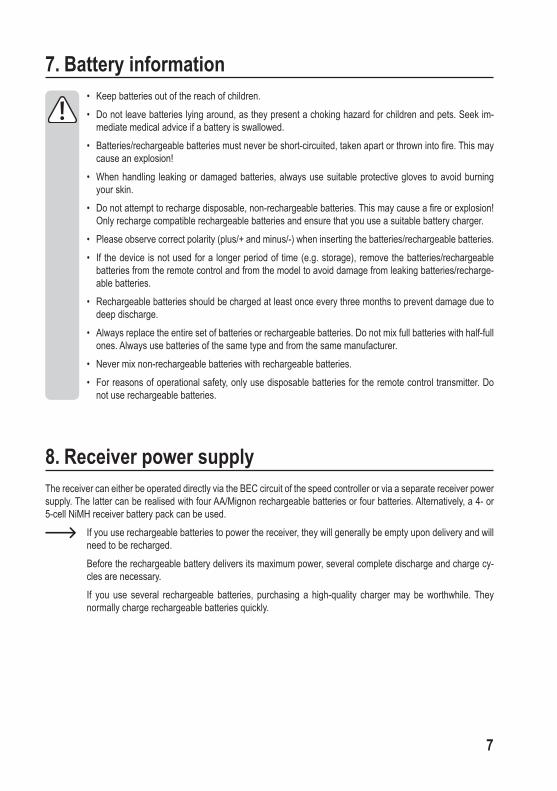
7. Battery information• Keep batteries out of the reach of children.• Do not leave batteries lying around, as they present a choking hazard for children and pets. Seek im-
mediate medical advice if a battery is swallowed.• Batteries/rechargeable batteries must never be short-circuited, taken apart or thrown into fire. This may
cause an explosion!• When handling leaking or damaged batteries, always use suitable protective gloves to avoid burning
your skin. • Do not attempt to recharge disposable, non-rechargeable batteries. This may cause a fire or explosion!
Only recharge compatible rechargeable batteries and ensure that you use a suitable battery charger.• Please observe correct polarity (plus/+ and minus/-) when inserting the batteries/rechargeable batteries. • If the device is not used for a longer period of time (e.g. storage), remove the batteries/rechargeable
batteries from the remote control and from the model to avoid damage from leaking batteries/recharge-able batteries.
• Rechargeable batteries should be charged at least once every three months to prevent damage due to deep discharge.
• Always replace the entire set of batteries or rechargeable batteries. Do not mix full batteries with half-full ones. Always use batteries of the same type and from the same manufacturer.
• Never mix non-rechargeable batteries with rechargeable batteries. • For reasons of operational safety, only use disposable batteries for the remote control transmitter. Do
not use rechargeable batteries.
8. Receiver power supplyThe receiver can either be operated directly via the BEC circuit of the speed controller or via a separate receiver power supply. The latter can be realised with four AA/Mignon rechargeable batteries or four batteries. Alternatively, a 4- or 5-cell NiMH receiver battery pack can be used.
If you use rechargeable batteries to power the receiver, they will generally be empty upon delivery and will need to be recharged.
Before the rechargeable battery delivers its maximum power, several complete discharge and charge cy-cles are necessary.
If you use several rechargeable batteries, purchasing a high-quality charger may be worthwhile. They normally charge rechargeable batteries quickly.
8
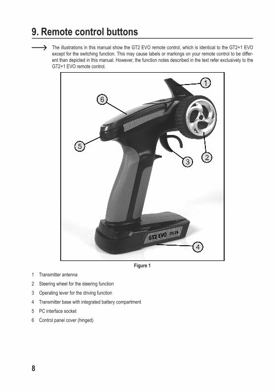
9. Remote control buttons The illustrations in this manual show the GT2 EVO remote control, which is identical to the GT2+1 EVO
except for the switching function. This may cause labels or markings on your remote control to be differ-ent than depicted in this manual. However, the function notes described in the text refer exclusively to the GT2+1 EVO remote control.
Figure 11 Transmitter antenna 2 Steering wheel for the steering function3 Operating lever for the driving function4 Transmitter base with integrated battery compartment5 PC interface socket6 Control panel cover (hinged)

9
If you open the control panel cover upwards, you have access to the other control elements of the transmitter.
Figure 2
7 Reverse switch for the driving function8 Green LED for the display of low voltage and special functions9 Dual rate button for the steering function10 Power ON / OFF switch11 Trim button for the driving function12 Trim button for the steering function13 Red LED for the operational control 14 Operating button for the pairing function/switching function of channel 315 Reverse switch for the steering function

10
10. Using the transmitter The numbers used in these instructions refer to the illustration alongside the text or the illustrations within
the respective section. Cross-references to other figures are indicated with the corresponding figure num-ber.
a) Inserting the batteriesTo power the transmitter, you need four alkaline batteries, size AA/Mignon. Proceed as follows to insert the batteries:The battery compartment lid (1) is located on the bottom of the transmitter. Press the corrugated surface (2) and slide the cover off in the direction of the arrow.Now insert four batteries into the battery compartment. Ensure the correct polarity of each of the cells. The nega-tive pole (housing) of the battery (3) must be in contact with the spiral spring (4). A corresponding note (5) can also be found on the bottom of the battery compartment. Slide the lid back on and ensure that it clicks into place.
Figure 3

11
b) Switching on the transmitterWhen the new batteries have been inserted, switch on the transmitter for testing purposes using the on/off switch (see also Figure 2, Pos. 10). To do this, move the control knob from the left (OFF) to the right (ON). The red LED for the operation control (see also Figure 2, Pos. 13) lights up and shows you the switched-on status of the transmitter. The green LED for the low voltage indicator (see also Figure 2, Pos. 8) lights up permanently and signals the adequate power supply of the transmitter.If the power supply drops below 4.3 V, the green low volt-age indicator will start flashing. In this case, you should stop operating your model as quickly as possible. To continue operation of the transmit-ter, new batteries must be inserted. After checking the correct function of the transmitter, switch it off again.
Figure 4
12
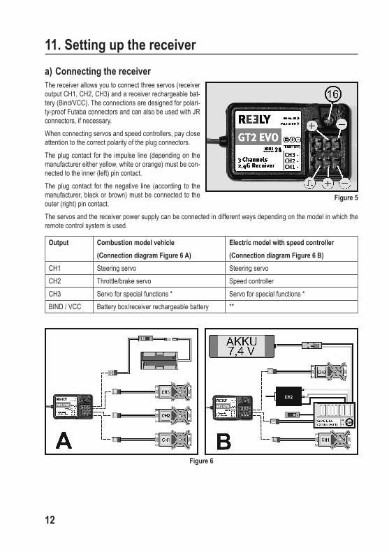
11. Setting up the receivera) Connecting the receiverThe receiver allows you to connect three servos (receiver output CH1, CH2, CH3) and a receiver rechargeable bat-tery (Bind/VCC). The connections are designed for polari-ty-proof Futaba connectors and can also be used with JR connectors, if necessary.When connecting servos and speed controllers, pay close attention to the correct polarity of the plug connectors. The plug contact for the impulse line (depending on the manufacturer either yellow, white or orange) must be con-nected to the inner (left) pin contact. The plug contact for the negative line (according to the manufacturer, black or brown) must be connected to the outer (right) pin contact. The servos and the receiver power supply can be connected in different ways depending on the model in which the remote control system is used.
Output Combustion model vehicle (Connection diagram Figure 6 A)
Electric model with speed controller(Connection diagram Figure 6 B)
CH1 Steering servo Steering servoCH2 Throttle/brake servo Speed controllerCH3 Servo for special functions * Servo for special functions *BIND / VCC Battery box/receiver rechargeable battery **
Figure 6
Figure 5

13
* The servo for special functions at receiver output 3 is operated with the operating button for channel 3 (see Figure 2, Pos. 14). A switching module can also be connected instead of a servo.
** For an electronic model with an electronic speed controller, a separate receiver battery at the Bind/VCC connec-tor is only required if the speed controller used does not have a BEC circuit. For further information, refer to the technical documents of the controller.
Warning! If you still use an old mechanical speed controller that has a BEC plug, do not use it to power the receiver.
The voltage applied to this connector is too high. Instead, use a separate power supply with four AA/Mignon rechargeable batteries or a 4- to 5-cell NiMH receiver battery.
Turn on the transmitter and then put the receiver into operation. If the transmitter and receiver are correctly connected (normally set at the factory), the red control LED in the receiver lights up (see Figure 5, Pos. 16). Check the correct function of the receiver and the connected servos and then switch it off again.
b) Installing the receiverThe installation of the receiver depends on the model. For this reason, you should always follow the recommendations of the model manufacturer regarding receiver installation. Independent of this, you should always try to mount the receiver so that it is optimally protected from dust, dirt, mois-ture, heat and vibrations. Two-sided adhesive foam (servo tape) or even rubber rings that hold the foam-wrapped receiver securely in place are suitable for fastening.
Warning! The aerial wire (1) has a precisely determined
length. So do not wind up, wrap or cut the aerial wire.
This would severely limit the range and thus present a significant security risk when operat-ing a model.
Guide the antenna wire up through an opening in the model. It is best to use the antenna tubes enclosed with the remote control.
Figure 7
14
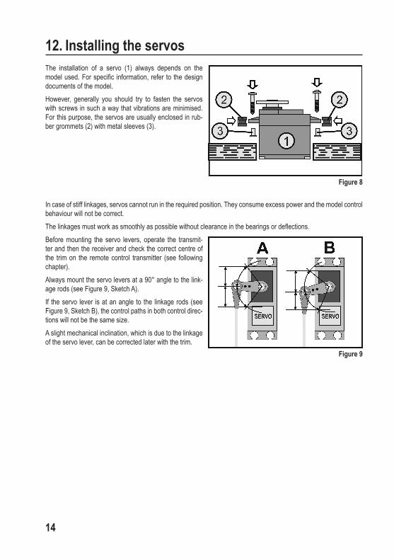
12. Installing the servosThe installation of a servo (1) always depends on the model used. For specific information, refer to the design documents of the model. However, generally you should try to fasten the servos with screws in such a way that vibrations are minimised. For this purpose, the servos are usually enclosed in rub-ber grommets (2) with metal sleeves (3).
In case of stiff linkages, servos cannot run in the required position. They consume excess power and the model control behaviour will not be correct. The linkages must work as smoothly as possible without clearance in the bearings or deflections.Before mounting the servo levers, operate the transmit-ter and then the receiver and check the correct centre of the trim on the remote control transmitter (see following chapter).Always mount the servo levers at a 90° angle to the link-age rods (see Figure 9, Sketch A).If the servo lever is at an angle to the linkage rods (see Figure 9, Sketch B), the control paths in both control direc-tions will not be the same size.A slight mechanical inclination, which is due to the linkage of the servo lever, can be corrected later with the trim.
Figure 8
Figure 9

15
13. Trimming the controlsThe trim serves primarily to correct a slight skew of the servo levers due to the linkage and the associated uneven control movements. In addition, you still have the opportunity to slightly adjust the model during operation, for exam-ple, when the drive is not straight although the steering wheel is in the central position.The steering arms should be adjusted so that there is a 90° angle between the servo lever and the steering arms. This will ensure that the model travels in a straight line. The GT2+1 EVO remote control has a sensitive digital trim, with which the steering (CH1) and the driving functions (CH2) can be set individually with two buttons, respectively.
a) Trimming the steering wheelPress and hold the lower of the two trim buttons (-) for the steering trim (see also Figure 2, Pos. 12). The green LED display (see also Figure 2, Pos. 8) starts to flicker after some time. When the receiving system is switched on, the servo lever of the steering servo will gradually turn from the centre position to the end of the trim area. When the green LED stops flickering and stays lit again, the end of the trim range is reached and the servo lever stops.Now press and hold the upper of the two trim buttons (+) for the steering trim (12). The green LED indicator (8) starts to flicker again after some time and the servo lever returns to the centre position. If the green LED flashes twice briefly, release the trim button immediately. The centre position has been reached and the set value is saved automatically. Even after switching off and on, the last set value is retained.If the centre position of the digital trim for the steering has been set on the transmitter, the position of the servo lever on the steering servo can be checked and, if necessary, the lever can be mounted in the correct position. Slight inclina-tions due to the servo lever interlock can then be corrected using the trim.
Practical tips: The trim for the steering function is exactly in the centre when the lever of the steering servo at the test does
not move by pressing the reverse switch (see Figure 2, Pos. 15). The steering wheel must be in the centre position.
b) Setting the driving trimWhen using a gas-powered model with throttle/brake servo, the trim setting is the same as for the steering servo. However, to set the trim value, the two trim buttons for the drive trim are used (see Figure 10, Pos. 11).When using an electric model with the speed controller, the trim must also be set to the average value. If the speed controller does not have the ability to program the forward, stop and reverse positions, the centre position of the trim must be set so that the drive motor is off when the drive control lever (see Figure 1. Pos. 3) is not engaged.
Figure 10

16
14. Checking the steering and driving functionsNow connect the servos or speed controllers used in your model and the power supply to the receiver.
For a better understanding, the steering function is demonstrated using the example of a model car. To prevent the model from unintentionally starting when checking the control and driving functions, place the model with the chassis on a suitable base (wooden block or similar). The wheels should be able to turn freely.
a) Checking and setting the steering functionTurn on the transmitter and, if you have not already done so, set the trim in the centre position for the drive and steer-ing functions according to the instructions in Chapter 13. Then switch on the receiver. If you have connected and mounted everything correctly, the steering of the model should react to the rotary movements of the steering wheel (see Figure 1, Pos. 2). When the steering wheel is in the centre position, the wheels should be straight. If the wheels are at an angle even though the steering wheel is in the centre position, check the correct position of the lever on the steering servo. The steering linkage rods can be readjusted, if necessary.If you steer the steering wheel to the left on the transmitter, the wheels on the vehicle should turn to the left (see Figure 11, Sketch A). If you turn to the right, the wheels should turn to the right (see Figure 11, Sketch B).
Figure 11
Warning! The operation of the steering wheel on the transmitter requires only slight force. Therefore, it is absolutely
sufficient if you operate the steering wheel only with your fingertips. Attempting to turn the steering wheel with increased force when reaching the end stop can lead to the destruction of the steering mechanism in the transmitter.

17
If the wheels turn in exactly the opposite direction as shown in Figure 11, you can use the reverse switch for the steering function (15) to switch the effective direction of the steering wheel and thus the direction of rotation of the steering servo.
It may then be necessary to set the steering trim again.
Important! Set the linkage rods on your model so that the full steering deflection to the left and right is achieved without
any mechanical impact or limitation on the steering. If the steering deflection is too large when operating the model, it can be reduced by means of the dual rate
buttons for the steering function (see Figure 12, Pos. 9). If you press and hold the lower button (-), the green LED will flicker and the maximum possible steering deflection will be reduced. If the upper button is pressed and held, the steering deflection increases again. If you turn the control wheel on the transmitter fully to the side during setting, the setting change can be easily observed.The setting of the maximum steering deflection affects both steering directions simultaneously. The set value is stored automatically and remains even after switching the remote control off and on again.
Figure 12

18
b) Checking and setting the driving functionIf you pull the operating lever for the driving function (see Figure 1, Pos. 3) as far as it will go in the direction of the handle, the model should accelerate (see Figure 13, Sketch A). If the lever is pushed forwards, the model should brake or switch to reverse drive (see Figure 13, Sketch B).
Figure 13
If the drive of your model behaves exactly the opposite to the illustration shown in Figure 13, you can use the reverse switch for the driving function (see Figure 12, Pos. 7) to switch the operating direction of the operating lever.
Important! For a model with an internal combustion engine, adjust the carburettor and brake linkage rods so that the
throttle/brake servo is not mechanically limited. The trim setting for the driving function must be in the mid-dle position.
For a model with an electronic speed controller, different positions of the operating lever for the driving function (for-ward, stop, reverse) may have to be programmed in the speed controller. Further related information can be found in the documents for the speed controller. If the speed controller is not programmable, set the trim so that the vehicle is stationary when the operating lever for the driving function is in the middle position.

19
15. Checking the switching functionIn addition to driving and steering functions, the GT 2+1 EVO remote control also offers the option of connecting and controlling a third servo on the receiver.If the operating button for channel 3 (also see Figure 2, Pos. 14) is pressed on the remote control, the output lever of the servo connected to the receiver output 3 runs from one end position to the other end position (see Figure 14 below). The function can be used, for example, to control a special mechanical function in a model.
Important! Because the two end positions cannot be set
electronically, any linkage rods must be ad-justed so that the servo on channel 3 is not mechanically limited in its rotational movement.
As an alternative to a servo, a switching module can also be connected to receiver output 3. Thus it is possible, for example, to turn the light functions on and off on the model by remote control as well.After you have checked or set the correct driving, steer-ing and switching function, first switch off the receiver and then the transmitter.The model is now ready for the first test drive.
Figure 14

20
16. Fail-safe functionYour remote control receiver gives you the ability to put the throttle servo or electronic speed controller in a specific position or in the stop function if a correct remote control signal is no longer received in the event of a fault. If the neutral position (centre position of the driving function control lever) is set to the fail-safe position, the vehicle will automatically coast if the radio transmission is disturbed or the model moves out of the transmitter range of the remote control. But you can also choose any brake position (for example, 50% braking effect in a combustion model vehicle) as a fail-safe position. In this case, when setting the fail-safe function, you should fix the control lever for the driving function in the desired position with a rubber ring.To set the fail-safe setting, proceed as follows:• Move the operating lever to the desired position.• Turn the transmitter and then the receiver.• Then press and hold the fail-safe button (17) on the
receiver.• The LED (16) in the receiver flashes twice and then
lights up again solidly.• Release the button in the receiver.• The fail-safe position is now saved.• The stored fail-safe position remains stored even after
the receiver has been switched off and on again.
Then carry out a function test, proceeding as follows:When using a throttle servo, you can give a little gas while the engine is stopped and then switch off the transmitter. The throttle servo must then run into the stored fail safe position after a short time. For an electric model with an electronic speed controller, the vehicle should be jacked up so that the wheels can rotate freely for the test. Then start the vehicle as usual. Move the operating lever for the driving function toward the handle so that the electric motor starts at low speed and the wheels spin.If you switch off the transmitter now, the electric motor should stop if previously stored as the fail-safe position for the centre position of the operating lever for the driving function.
Figure 15

21
17. Switching the digital codingYour remote control transmitter provides the option of controlling receivers with AFHDS and AFHDS2A digital coding. The transmitter is factory-set to the enclosed AFHDS2A-coded receiver. If you want to operate a REELY receiver with AFHDS digital coding, the transmitter must first be changed over and then the receiver must be connected to the transmitter (see following chapter).To switch the digital coding on the transmitter, proceed as follows.• Switch off the transmitter.• Move the steering wheel for the steering function (see Figure 1, Pos. 2) to one side until it stops and hold it in place.• Press and hold the pairing button (see Figure 2, Pos. 14).• With the steering wheel in the steering position and the pairing button pressed, switch on the transmitter with the
on/off switch.• Release the steering wheel and the pairing button.• If the green LED for the low voltage indicator is flashing continuously, the transmitter has switched to the AFHDS
digital coding. If the green LED flashes intermittently, the transmitter has switched to AFHDS2A digital coding.
• Pressing the pairing button again will save the currently set digital coding.• Turn the transmitter off and then on again to have the remote control transmit in the set digital coding.
Important: The receiver supplied with the "GT2+1 EVO" remote control system works with AFHDS2A digital coding.
Therefore, always make sure to program the correct coding on the transmitter!

22
18. Pairing functionFor the sender and receiver to work together, they must be paired together with the same digital coding. When deliv-ered, the transmitter and receiver are paired and can be used immediately. Renewing the pairing setting is required primarily after a change of transmitter or receiver or to correct for interference.Before pairing the receiver with the transmitter, check whether the transmitter works in the correct digital coding (see the previous chapter).To perform the pairing function, proceed as follows:• Transmitter and receiver must be in the immediate vicinity (about 50 cm distance).• Switch off the transmitter.• Disconnect any connected servos from the receiver.• Connect the enclosed programming plug (18) to the
BIND/VCC connector of the receiver. • The power supply of the receiver (receiver battery or
speed controller with BEC) is connected to output CH3 of the receiver.
• Turn on the receiver. The LED in the receiver (16) starts flashing quickly.
• Press the pairing button on the transmitter (see Figure 2, Pos. 14) and hold it down.
• Turn on the transmitter while holding the button. The low voltage indicator on the transmitter flashes.
• When the LED in the receiver (2) flashes slowly after a few seconds, the pairing process is completed.
• Release the pairing button on the transmitter.• Turn off the receiver and the transmitter and remove the programming connector.• Reconnect the servos/controllers to the receiver.• Check the function of the system. If the system does not work properly, perform the procedure again or check the
digital coding of the transmitter. If you have switched the transmitter to AFHDS digital coding and pair with an AFHDS receiver, the LED in
the receiver will not flash slowly after pairing, but will light up solidly.
Figure 16

23
19. Simulator functionIf required, you can also use the transmitter on the PC for simulation purposes or games. In this case, you will need a USB interface cable and appropriate software for the computer (e.g., car racing games, etc.).The USB interface cable is connected to the PC interface socket on the left side of the transmitter (see Figure 1, Pos. 5). When properly connected, installed and turned on, the transmitter is recognised by the operating system (for example, at least Windows XP or higher) and can be used as a standard joystick. For all other information, refer to the user manual of the USB interface cable.
20. Maintenance and cleaningThis product does not require maintenance. Never attempt to disassemble the product (except for inserting or replac-ing the batteries as described in these instructions).Clean the exterior of the remote control with a soft, dry cloth or brush. Never use abrasive cleaning agents or chemical solutions, as these may damage the surface of the case.
21. Declaration of Conformity (DOC)Conrad Electronic SE, Klaus-Conrad-Straße 1, D-92240 Hirschau, hereby declares that this product conforms to the 2014/53/EU directive.
Click on the following link to read the full text of the EU Declaration of Conformity: www.conrad.com/downloads Select a language by clicking on the corresponding flag symbol, and then enter the product order number
in the search box. The EU Declaration of Conformity is available for download in PDF format.

24
22. TroubleshootingEven though the remote control system was built to the latest available technology, malfunctions or faults might still occur. The following section shows you how to troubleshoot potential problems.
Problem SolutionThe transmitter does not respond.
• Check the transmitter batteries.• Check the polarity of the batteries.• Check the function switch.
The servos do not react. • Check the receiver batteries or rechargeable batteries.• Test the switchgear cable.• Test the BEC function of the controller.• Check the polarity of the servo connector.• Check the digital coding.• Carry out the pairing function.
Servos do not respond and the LED in the receiver flashes slowly.
• Check the function of the remote control transmitter.• Carry out the pairing function.• Switch the coding on the transmitter and pair the receiver again.
The servos shake. • Check batteries or rechargeable batteries of the transmitter and model.• Dry any humidity in the receiver with a hair dryer.
A servo is humming. • Check the receiver batteries or rechargeable batteries.• Check that the linkage rods are running smoothly.• Operate servo without servo lever for test purposes.
The system has a low range. • Check batteries or rechargeable batteries of the transmitter and model.• Check the receiver antenna for damages and electrical continuity.• Re-install the receiver antenna in the model for test purposes.
The transmitter turns off straight away or after a short while.
• Check or replace the transmitter batteries.
Vehicle does not steer. • Check that the linkage rods are running smoothly.• Check the steering servo.• Check the steering servo connection on the receiver.• Increase the dual rate value on the transmitter.

25
23. Disposala) Product
Electronic devices are recyclable waste and must not be disposed of in the household waste. At the end of its service life, dispose of the product according to the relevant statutory regulations.
Remove any inserted batteries and dispose of them separately from the product.
b) (Rechargeable) batteriesYou as the end user are required by law (Battery Ordinance) to return all used batteries/rechargeable batteries. Dis-posing of them in the household waste is prohibited.
Contaminated (rechargeable) batteries are labelled with this symbol to indicate that disposal in the domes-tic waste is forbidden. The designations for the heavy metals involved are: Cd = Cadmium, Hg = Mercury, Pb = Lead (name on (rechargeable) batteries, e.g. below the trash icon on the left).
Used (rechargeable) batteries can be returned to collection points in your municipality, our stores or wherever (re-chargeable) batteries are sold.You thus fulfil your statutory obligations and contribute to environmental protection.

26
24. Technical Dataa) TransmitterFrequency band ................................................2.405 - 2.475 GHzTransmission power..........................................<20 dBmTransmitter range .............................................approx. 200 mNumber of channels .........................................3Signal output .....................................................3.5 mm jack (PPM)Operating voltage .............................................6 V/DC via 4 AA/Mignon batteries Dimensions (W x H x D) ...................................160 x 210 x 95 mm Weight without batteries ...................................approx. 240 g
b) ReceiverFrequency band ................................................2.405 - 2.475 GHzNumber of channels .........................................3Coding ..............................................................AFHDS2APlug-in system ..................................................Futaba/Graupner JROperating voltage .............................................4.0 - 6.5 V/DC via 4 AA/Mignon batteries or rechargeable batteries Dimensions (W x H x D) ...................................35 x 22 x 12 mm Weight ..............................................................approx. 5 g

27

This is a publication by Conrad Electronic SE, Klaus-Conrad-Str. 1, D-92240 Hirschau (www.conrad.com). All rights including translation reserved. Reproduction by any method, e.g. photocopy, microfilming, or the capture in electronic data processing systems require the prior written approval by the editor. Reprinting, also in part, is prohibited. This publication represent the technical status at the time of printing.Copyright 2019 by Conrad Electronic SE.
1897778_V1_0219_02_VTP_m_en


![gt2] (TOEFL (VET), (BEST](https://static.fdocuments.us/doc/165x107/61bd10de61276e740b0f0053/gt2-toefl-vet-best.jpg)