Numerical Experiments of Counterflowing Jet Effects on ... · Numerical Experiments of...
22
1 Numerical Experiments of Counterflowing Jet Effects on Supersonic Slender-Body Configurations Balaji Shankar Venkatachari 1 National Institute of Aerospace, Hampton, VA 23666 Michael Mullane 2 University of Alabama at Birmingham, Birmingham, AL 35294 Gary C. Cheng 3 University of Alabama, Tuscaloosa, AL 35487 Chau-Lyan Chang 4 NASA Langley Research Center, Hampton, VA 23681 Previous studies have demonstrated that the use of counterflowing jets can greatly reduce the drag and heat loads on blunt-body geometries, especially when the long penetration mode jet condition can be established. Previously, the authors had done some preliminary numerical studies to determine the ability to establish long penetration mode jets on a typical Mach 1.6 slender configuration, and study its impact on the boom signature. The results indicated that a jet with a longer penetration length was required to achieve any impact on the boom signature of a typical Mach 1.6 slender configuration. This paper focuses on an in-depth parametric study, done using the space-time conservation element solution element Navier-Stokes flow solver, for investigating the effect of various counterflowing jet conditions/configurations on two supersonic slender-body models (cone-cylinder and quartic body of revolution). The study is aimed at gaining a better understanding of the relationship between the shock penetration length and reduction of drag and boom signature for these two supersonic slender-body configurations. Different jet flow rates, Mach numbers, nozzle jet exit diameters and jet-to-base diameter ratios were examined. The results show the characteristics of a short-to-long-to-short penetration-mode pattern with the increase of jet mass flow rates, observed across various counterflowing jet nozzle configurations. Though the optimal shock penetration length for potential boom-signature mitigation is tied to the long penetration mode, it often results in a very unsteady flow and leads to large oscillations of surface pressure and drag. Furthermore, depending on the geometry of the slender body, longer jet penetration did not always result in maximum drag reduction. For the quartic geometry, the maximum drag reduction corresponds well to the longest shock penetration length, while this was not the case for the cone-cylinder—as the geometry was already optimized for drag. Numerical results and assessments obtained from this parametric study along with the recommendation for future implementation of counterflowing jets as a means for drag and noise reduction are detailed in this paper. Nomenclature d j = Jet exit diameter, mm (or inch) d m = Model diameter, mm (or inch) h = distance away from the centerline of the body, cm L = Length, cm L p = Jet penetration length, cm (or inch) 1 Research Engineer, National Institute of Aerospace, email: [email protected], Senior Member AIAA. 2 Graduate Research Assistant, Dept. of Mechanical Engineering, e-mail: [email protected]. 3 Associate Professor, Dept. of Aerospace Engineering & Mechanics, email: [email protected], AIAA Associate Fellow. 4 Aerospace Technologist, Computational AeroSciences Branch, email: [email protected], AIAA Associate Fellow. https://ntrs.nasa.gov/search.jsp?R=20160006022 2018-05-31T00:03:15+00:00Z
Transcript of Numerical Experiments of Counterflowing Jet Effects on ... · Numerical Experiments of...
1
Numerical Experiments of Counterflowing Jet Effects on
Supersonic Slender-Body Configurations
Balaji Shankar Venkatachari1
National Institute of Aerospace, Hampton, VA 23666
Michael Mullane2
University of Alabama at Birmingham, Birmingham, AL 35294
Gary C. Cheng3
University of Alabama, Tuscaloosa, AL 35487
Chau-Lyan Chang4
NASA Langley Research Center, Hampton, VA 23681
Previous studies have demonstrated that the use of counterflowing jets can greatly reduce the
drag and heat loads on blunt-body geometries, especially when the long penetration mode jet
condition can be established. Previously, the authors had done some preliminary numerical studies
to determine the ability to establish long penetration mode jets on a typical Mach 1.6 slender
configuration, and study its impact on the boom signature. The results indicated that a jet with a
longer penetration length was required to achieve any impact on the boom signature of a typical
Mach 1.6 slender configuration. This paper focuses on an in-depth parametric study, done using the
space-time conservation element solution element Navier-Stokes flow solver, for investigating the
effect of various counterflowing jet conditions/configurations on two supersonic slender-body
models (cone-cylinder and quartic body of revolution). The study is aimed at gaining a better
understanding of the relationship between the shock penetration length and reduction of drag and
boom signature for these two supersonic slender-body configurations. Different jet flow rates,
Mach numbers, nozzle jet exit diameters and jet-to-base diameter ratios were examined. The
results show the characteristics of a short-to-long-to-short penetration-mode pattern with the
increase of jet mass flow rates, observed across various counterflowing jet nozzle configurations.
Though the optimal shock penetration length for potential boom-signature mitigation is tied to the
long penetration mode, it often results in a very unsteady flow and leads to large oscillations of
surface pressure and drag. Furthermore, depending on the geometry of the slender body, longer jet
penetration did not always result in maximum drag reduction. For the quartic geometry, the
maximum drag reduction corresponds well to the longest shock penetration length, while this was
not the case for the cone-cylinder—as the geometry was already optimized for drag. Numerical
results and assessments obtained from this parametric study along with the recommendation for
future implementation of counterflowing jets as a means for drag and noise reduction are detailed
in this paper.
Nomenclature
dj = Jet exit diameter, mm (or inch)
dm = Model diameter, mm (or inch)
h = distance away from the centerline of the body, cm
L = Length, cm
Lp = Jet penetration length, cm (or inch)
1 Research Engineer, National Institute of Aerospace, email: [email protected], Senior Member AIAA.
2 Graduate Research Assistant, Dept. of Mechanical Engineering, e-mail: [email protected].
3 Associate Professor, Dept. of Aerospace Engineering & Mechanics, email: [email protected], AIAA Associate
Fellow. 4 Aerospace Technologist, Computational AeroSciences Branch, email: [email protected], AIAA Associate
Fellow.
https://ntrs.nasa.gov/search.jsp?R=20160006022 2018-05-31T00:03:15+00:00Z

2
Mj = Counterflowing jet nozzle Mach number
M∞ = Freestream Mach number
M∞ = Freestream Mach number
p = Pressure, atm
p∞ = Freestream static pressure, atm
Pt,j
= Total pressure of counterflowing jet, atm
Pt,∞
= Total freestream pressure, atm
Tt,∞
= Total freestream temperature, K
x, y = Cartesian coordinates
I. Background and Introduction
Counterflowing jets emanating from blunt bodies or bodies of revolution against a supersonic/hypersonic
freestream have been the subject of several experimental studies,1-8
as well as a small number of computational studies.9-14
Two different modes of jet interaction with the oncoming freestream exist, namely the short penetration mode (SPM) and
long penetration mode (LPM), pictorially represented in Fig. 1. Both these modes have potential benefits for drag or thermal
load reduction. Depending on the location of the jet relative to the face of the vehicle forebody, both thermal load reduction
and drag reduction/augmentation on the body are possible. The LPM jet, when issuing from a centrally located single
nozzle, often penetrates into the bow shock in front of the body, weakening its strength or dispersing it, creating a complex
flow interaction. As a result, it significantly alters the flowfield around the body, thereby having a potential to be applied as
a means to reduce sonic boom for vehicles travelling at supersonic speeds.
Sonic boom mitigation remains an active field of research since the 1960s,15
although the theory of sonic boom16-18
and the methods for its prediction19-21
have been well established. In 1969, Miller and Carlson22
explored an idea similar to
that of counterflowing jets for sonic boom mitigation, where through the addition of heat/forcefields, they attempted to
create a long, well-shaped phantom body that envelops the aircraft. The conclusion of their study was that such an idea
would necessitate power requirements that are at least twice of what is needed to sustain steady flight, even if the system
required for achieving heat/mass addition was assumed to be weightless. More recently, Fomin et al.23
have also explored
the concept of using counterflowing jets as a boom mitigation technique, based on their prior experience with
counterflowing jets.3 Their experimental study focused predominantly on SPM jets, giving limited attention to LPM jets.
The conclusion from their study was that counterflowing jets did not yield significant boom signature reduction for the
cone-cylinder type geometry they had investigated.
(a) SPM: features of the stable flowfield for a central nozzle
configuration.
(b) LPM: features of an unstable flowfield for a central
nozzle configuration
Figure 1. Characterization of the flowfield structure for a jet emanating from a central nozzle against a supersonic
freestream.
Despite the conclusions of Miller and Carlson22
and Fomin et al.,23
we intended to explore the potential of LPM jets
and their application in boom and drag mitigation in a more thorough manner, using computational studies. Our improved
understanding of the LPM jets through earlier investigations9, 14
drove this study. In this regard, the authors of this paper had
previously conducted a pilot computational study24
on the use of the LPM of a counterflowing supersonic jet for sonic boom
mitigation. In that study, the jets emanated from the nose of two slender-body geometries25, 26
(a cone-cylinder and a quartic
body of revolution), which were of interest to the High Speed project under NASA’s Fundamental Aeronautics Program
3
(FAP). Based on the understanding that LPM jets exist under a narrow range of flow conditions, the main focus of that
study was to investigate the feasibility of obtaining an LPM jet issuing from these two slender-body configurations against
low supersonic freestream conditions. Numerical computations were carried out to study a limited range of counterflowing
jet conditions and nozzle geometries for establishing LPM jets. The results indicated that the jet penetration lengths (i.e.,
shock stand-off distance) achieved might not be long enough to gain substantial reduction in boom signature. In this study,
we extend the previous preliminary study with a wider range of key parameters associated with counterflowing jet
conditions, and explore the optimal condition for the longest jet penetration length. The objectives of the present numerical
study are (i) to assess the ability to establish counterflowing LPM jet and its associated penetration length as well as
interaction with the shock system around the body of a cone-cylinder25
and a quartic geometry26
at a freestream Mach
number of 1.6; (ii) to determine the effects of key geometric parameters and flow conditions on the jet penetration length
and drag change; (iii) to understand the correlation between the jet penetration length and drag change; and (iv) to assess the
influence of the LPM jet on the farfield pressure signature. The numerical method used in this study is the space-time
conservation element, solution element (CESE) method,27-29
a time-accurate numerical framework for unstructured meshes
designed to enforce strong flux conservation and capture shocks without a need for any ad hoc numerical tuning. The
ability of the CESE method to correctly predict the occurrence of LPM jets, as well as its behavior, has been demonstrated
in our previous studies.9, 14
II. Test Geometries and Flow Conditions
Because of the interest of these geometries to the High Speed project, all the numerical computations of this study
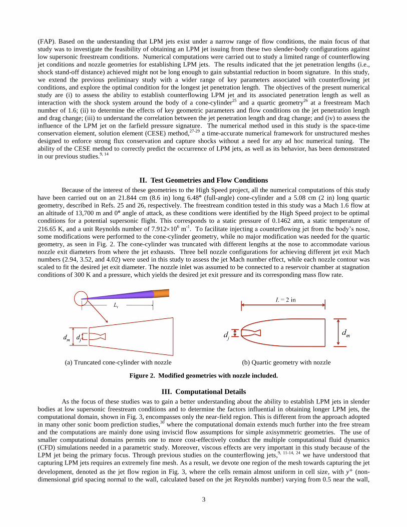
have been carried out on an 21.844 cm (8.6 in) long 6.48° (full-angle) cone-cylinder and a 5.08 cm (2 in) long quartic
geometry, described in Refs. 25 and 26, respectively. The freestream condition tested in this study was a Mach 1.6 flow at
an altitude of 13,700 m and 0° angle of attack, as these conditions were identified by the High Speed project to be optimal
conditions for a potential supersonic flight. This corresponds to a static pressure of 0.1462 atm, a static temperature of
216.65 K, and a unit Reynolds number of 7.912106 m
-1. To facilitate injecting a counterflowing jet from the body’s nose,
some modifications were performed to the cone-cylinder geometry, while no major modification was needed for the quartic
geometry, as seen in Fig. 2. The cone-cylinder was truncated with different lengths at the nose to accommodate various
nozzle exit diameters from where the jet exhausts. Three bell nozzle configurations for achieving different jet exit Mach
numbers (2.94, 3.52, and 4.02) were used in this study to assess the jet Mach number effect, while each nozzle contour was
scaled to fit the desired jet exit diameter. The nozzle inlet was assumed to be connected to a reservoir chamber at stagnation
conditions of 300 K and a pressure, which yields the desired jet exit pressure and its corresponding mass flow rate.
(a) Truncated cone-cylinder with nozzle (b) Quartic geometry with nozzle
Figure 2. Modified geometries with nozzle included.
III. Computational Details
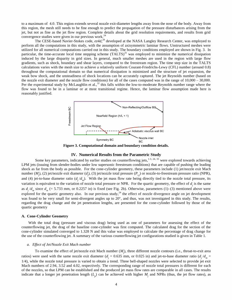
As the focus of these studies was to gain a better understanding about the ability to establish LPM jets in slender
bodies at low supersonic freestream conditions and to determine the factors influential in obtaining longer LPM jets, the
computational domain, shown in Fig. 3, encompasses only the near-field region. This is different from the approach adopted
in many other sonic boom prediction studies,30
where the computational domain extends much further into the free stream
and the computations are mainly done using inviscid flow assumptions for simple axisymmetric geometries. The use of
smaller computational domains permits one to more cost-effectively conduct the multiple computational fluid dynamics
(CFD) simulations needed in a parametric study. Moreover, viscous effects are very important in this study because of the
LPM jet being the primary focus. Through previous studies on the counterflowing jets,9, 11-14, 24
we have understood that
capturing LPM jets requires an extremely fine mesh. As a result, we devote one region of the mesh towards capturing the jet
development, denoted as the jet flow region in Fig. 3, where the cells remain almost uniform in cell size, with y+ (non-
dimensional grid spacing normal to the wall, calculated based on the jet Reynolds number) varying from 0.5 near the wall,
4
to a maximum of 4.0. This region extends several nozzle exit-diameter lengths away from the nose of the body. Away from
this region, the mesh still needs to be fine enough to predict the propagation of the pressure disturbances arising from the
jet, but not as fine as the jet flow region. Complete details about the grid resolution requirements, and results from grid
convergence studies were given in our previous work.24
The CESE-based Navier-Stokes code, ez4d,29
developed at the NASA Langley Research Center, was employed to
perform all the computations in this study, with the assumption of axisymmetric laminar flows. Unstructured meshes were
utilized for all numerical computations carried out in this study. The boundary conditions employed are shown in Fig. 3. In
particular, the time-accurate local time stepping scheme (TALTS)31
was employed to minimize the numerical dissipation
induced by the large disparity in grid sizes. In general, much smaller meshes are used in the region with large flow
gradients, such as shock, boundary and shear layers, compared to the freestream region. The time step size in the TALTS
calculations varies with the mesh size to achieve a relatively uniform Courant-Friedrichs-Lewy (CFL) number (around 0.8)
throughout the computational domain so that numerical dissipation is minimized and the structure of jet expansion, the
weak bow shock, and the unsteadiness of shock locations can be accurately captured. The jet Reynolds number (based on
the nozzle exit diameter and the nozzle flow conditions) for all of the cases computed was in the range of 10,000 – 30,000.
Per the experimental study by McLaughlin et al.,32
this falls within the low-to-moderate Reynolds number range where the
flow was found to be in a laminar or at most transitional regime. Hence, the laminar flow assumption made here is
reasonably justified.
Figure 3. Computational domain and boundary condition details.
IV. Numerical Results from the Parametric Study
Some key parameters, indicated by earlier studies on counterflowing jets,1-3, 24, 33
were explored towards achieving
LPM jets (issuing from slender-bodies under low supersonic freestream conditions) that are capable of pushing the leading
shock as far from the body as possible. For the cone-cylinder geometry, these parameters include (1) jet/nozzle exit Mach
number (Mj), (2) jet/nozzle exit diameter (d
j), (3) jet/nozzle total pressure (P
t,j) or nozzle-to-freestream pressure ratio (NPR),
and (4) jet-to-base diameter ratio (dj /d
m). With the jet mass flow rate being directly tied to the nozzle total pressure, its
variation is equivalent to the variation of nozzle total pressure or NPR. For the quartic geometry, the effect of dj is the same
as dj /d
m since d
m (= 5.733 mm, or 0.2257 in) is fixed (see Fig. 2b). Otherwise, parameters (1)–(3) mentioned above were
explored for the quartic geometry also. In our previous study,24
the effect of nozzle divergence angle on jet development
was found to be very small for semi-divergent angles up to 20, and thus, was not investigated in this study. The results,
regarding the drag change and the jet penetration lengths, are presented for the cone-cylinder followed by those of the
quartic geometry
A. Cone-Cylinder Geometry
With the total drag (pressure and viscous drag) being used as one of parameters for assessing the effect of the
counterflowing jet, the drag of the baseline cone-cylinder was first computed. The calculated drag for the section of the
cone-cylinder simulated converged to 1.328 N and this value was employed to calculate the percentage of drag change for
the use of the counterflowing jet. A summary of the various counterflowing jet configurations studied is given in Table 1.
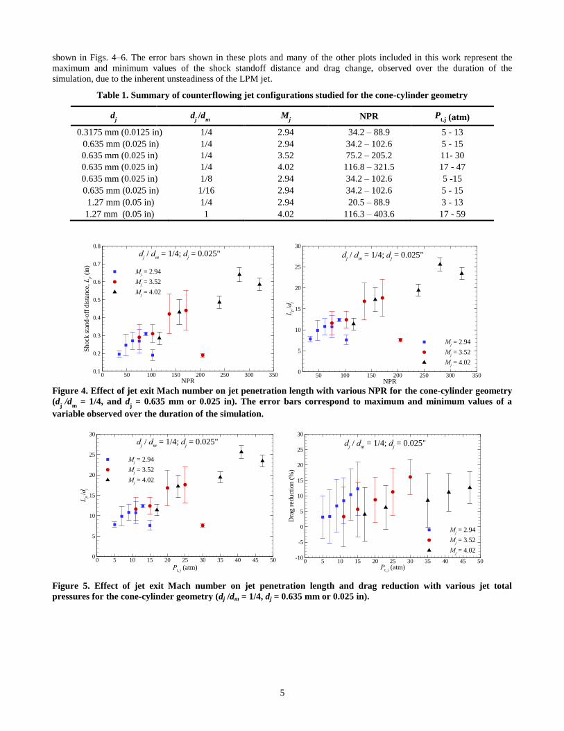
a. Effect of Jet/Nozzle Exit Mach number
To examine the effect of jet/nozzle exit Mach number (Mj), three different nozzle contours (i.e., throat-to-exit area
ratios) were used with the same nozzle exit diameter (dj = 0.635 mm, or 0.025 in) and jet-to-base diameter ratio (d
j /d
m =
1/4), while the nozzle total pressure is varied to obtain a trend. Three bell-shaped nozzles were selected to provide jet exit
Mach numbers of 2.94, 3.52 and 4.02, respectively. The corresponding range of nozzle total pressures is different for each
of the nozzles, so that LPM can be established and the produced jet mass flow rates are comparable in all cases. The results
indicate that a longer jet penetration length (Lp) can be achieved with higher M
j and NPRs (thus, the jet flow rates), as
5
shown in Figs. 4–6. The error bars shown in these plots and many of the other plots included in this work represent the
maximum and minimum values of the shock standoff distance and drag change, observed over the duration of the
simulation, due to the inherent unsteadiness of the LPM jet.
Table 1. Summary of counterflowing jet configurations studied for the cone-cylinder geometry
dj d
j /d
m M
j NPR P
t,j (atm)
0.3175 mm (0.0125 in) 1/4 2.94 34.2 – 88.9 5 - 13
0.635 mm (0.025 in) 1/4 2.94 34.2 – 102.6 5 - 15
0.635 mm (0.025 in) 1/4 3.52 75.2 – 205.2 11- 30
0.635 mm (0.025 in) 1/4 4.02 116.8 – 321.5 17 - 47
0.635 mm (0.025 in) 1/8 2.94 34.2 – 102.6 5 -15
0.635 mm (0.025 in) 1/16 2.94 34.2 – 102.6 5 - 15
1.27 mm (0.05 in) 1/4 2.94 20.5 – 88.9 3 - 13
1.27 mm (0.05 in) 1 4.02 116.3 – 403.6 17 - 59
Figure 4. Effect of jet exit Mach number on jet penetration length with various NPR for the cone-cylinder geometry
(dj
/dm
= 1/4, and dj = 0.635 mm or 0.025 in). The error bars correspond to maximum and minimum values of a
variable observed over the duration of the simulation.
Figure 5. Effect of jet exit Mach number on jet penetration length and drag reduction with various jet total
pressures for the cone-cylinder geometry (dj /dm = 1/4, dj = 0.635 mm or 0.025 in).
NPR
Shock
sta
nd
-off
dis
tance
, L
p (
in)
0 50 100 150 200 250 300 3500.1
0.2
0.3
0.4
0.5
0.6
0.7
0.8
Mj = 2.94
Mj = 3.52
Mj = 4.02
dj / d
m = 1/4; d
j = 0.025"
NPR
Lp
/dj
50 100 150 200 250 300 3500
5
10
15
20
25
30
Mj = 2.94
Mj = 3.52
Mj = 4.02
dj / d
m = 1/4; d
j = 0.025"
Pt, j
(atm)
Lp
/dj
0 5 10 15 20 25 30 35 40 45 500
5
10
15
20
25
30
Mj = 2.94
Mj = 3.52
Mj = 4.02
dj / d
m = 1/4; d
j = 0.025"
Pt, j
(atm)
Dra
g r
educt
ion (
%)
0 5 10 15 20 25 30 35 40 45 50-10
-5
0
5
10
15
20
25
30
Mj = 2.94
Mj = 3.52
Mj = 4.02
dj / d
m = 1/4; d
j = 0.025"
6
Figure 6. Effect of jet exit Mach umber on jet penetration length and drag reduction with various jet flow rates for
the cone-cylinder geometry (dj /d
m = 1/4, and d
j = 0.635 mm or 0.025 in).
Mj = 2.94
Mj = 3.52 M
j = 4.02
Figure 7. Instantaneous Mach contours showing the effect of jet exit Mach number on the jet development for the
cone-cylinder geometry. The x- and y-coordinates are given in inches. The nose tip of the unmodified cone-cylinder
geometry was at x = 0.
Jet flow rate ´104 (kg/s)
Lp
/dj
0 1 2 3 40
5
10
15
20
25
30
Mj = 2.94
Mj = 3.52
Mj = 4.02
dj / d
m = 1/4; d
j = 0.025"
Jet flow rate ´104 (kg/s)
Dra
g r
edu
ctio
n (
%)
0 1 2 3 4-10
-5
0
5
10
15
20
25
30
Mj = 2.94
Mj = 3.52
Mj = 4.02
dj / d
m = 1/4; d
j = 0.025"
7
The Mach number contours, corresponding to the longest Lp for each M
j for a given nozzle total pressure is shown in
Fig. 7. As can be seen from Fig. 7, even under conditions with the longest Lp, the jet penetration is unable to compensate for
the truncation in the length of the cone-cylinder (in Fig. 7, the tip of the unmodified cone-cylinder was at x = 0), which was
necessary for implementation of the counterflowing jet nozzle. Furthermore, for a given Mj, L
p increases over a range of
NPRs (and jet flow rates) to an optimal value and then decreases—an indication of the jet switching from LPM to SPM. The
data points corresponding to NPR = 102.6 for Mj = 2.94, and NPR = 205.2 for M
j = 3.52 in Fig. 4 are indicative of the
transition to SPM. The existence of a range of pressures at which the LPM jet regime can be established offers some
flexibility, in case the freestream condition changes continuously. This aspect could become important, especially during
vehicle acceleration/deceleration at supersonic speeds. In addition, drag reduction increases monotonically with NPR (and
jet flow rates) within the operating conditions studied. The characteristics of drag reduction for different Mj are similar,
which shows it is not directly linked to Lp, i.e., longer L
p does not necessarily produce larger drag reduction. Figure 8
depicts the unsteady nature of these LPM jets. The overall impact of the counterflowing jets on the flowfield near the nose
of the body is itself shown in Fig. 9, through a comparison of the computed density gradient contours for the unmodified
cone-cylinder and that of a truncated cone-cylinder which includes a counterflowing jet (Mj = 4.02;Pt,j = 35.0 atm).
Figure 8. Mach number contours at different time instances for the cone-cylinder (Mj = 4.02). The x- and y-
coordinates are given in inches.
8
Figure 9. Comparison of the computed density gradient contours for the unmodified cone-cylinder (top) and the
truncated cone-cylinder, which includes a counterflowing jet (bottom).
b. Effect of Jet/Nozzle Exit Diameter
To help understand the effect of the jet/nozzle exit diameter (dj) on the jet penetration length, the nozzle with M
j =
2.94 was examined for three different nozzle exit diameters (dj = 1.27, 2.54, and 5.08 mm, or 0.05, 0.1 and 0.2 in.,
respectively) with the jet-to-base diameter ratio remaining constant (dj
/dm = 1/4). The nozzle contour (bell-shape) was
scaled to achieve different exit diameters. Given that the same nozzle shape was used in this study, the range of jet total
pressures studied was roughly the same (3~15 atm) and the scaling accounted for the different mass flow rates. As shown
in Figs. 10–12, Lp increases with d
j for a given d
j /d
m and M
j, but their ratio (L
p /dj) is less sensitive to the change in d
j. Also,
for a given dj, L
p increases with NPR and jet flow rate to an optimal value and then decreases because the jet reverts back to
SPM. The optimal NPR and jet flow rate condition for obtaining maximum Lp varies slightly for the different nozzle exit
diameters. Similar to the jet Mach number effect, the correlation between Lp /dj
and NPR can be easily observed, compared
to looking at the variation in Lp with NPR alone. In addition, drag reduction increases with NPRs (and jet flow rates) within
the operating conditions studied. The characteristics of drag changes for different dj are similar and show that drag reduction
is not directly linked to Lp. Though Fig. 11 reveals that a larger jet diameter yields higher drag reduction for the same jet
total pressure (i.e., NPR), the main driver is the jet flow rate, as can be seen from Fig. 12. This effect occurs because a larger
jet diameter corresponds to a higher jet flow rate for a given jet total pressure. Furthermore, longer Lp in general produces a
larger drag oscillation, which may be disadvantageous from a vehicle controllability perspective.
9
Figure 10. Effect of jet diameter on shock standoff distance with various jet total pressures for the cone-cylinder
geometry (dj /d
m = 1/4 and M
j = 2.94).
Figure 11. Effect of jet diameter on shock standoff distance and drag reduction with various NPR for the cone-
cylinder geometry (dj /d
m = 1/4 and M
j = 2.94).
Figure 12. Effect of jet diameter on shock standoff distance and drag reduction with various jet flow rates for the
cone-cylinder geometry (dj /d
m = 1/4 and M
j = 2.94).
c. Effect of Jet-to-Base Diameter Ratio
Based on our previous study (Refs. 14 and 24), the jet-to-base diameter ratio (dj /d
m) is the most significant factor
affecting the formation of the LPM jet. The parameter dj /d
m determines the height of the forward facing step above nozzle
exit, which strongly influences the strength and pattern of flow recirculation in front of the truncated cone and the stability
Pt, j
(atm)
Shock
sta
nd
-off
dis
tance
, L
p (
in)
1 3 5 7 9 11 13 15 170
0.1
0.2
0.3
0.4
0.5
0.6
dj = 0.0125"
dj = 0.025"
dj = 0.05"
dj / d
m = 1/4; M
j = 2.94
Pt, j
(atm)
Lp /
dj
2 4 6 8 10 12 14 160
5
10
15
20
dj = 0.0125"
dj = 0.025"
dj = 0.05"
dj / d
m = 1/4; M
j = 2.94
NPR
Lp /
dj
10 30 50 70 90 1100
5
10
15
20
dj = 0.0125"
dj = 0.025"
dj = 0.05"
dj / d
m = 1/4; M
j = 2.94
NPR
Dra
g r
edu
ctio
n (
%)
10 20 30 40 50 60 70 80 90 100 110-20
-10
0
10
20
30
40
50
60
70
dj = 0.0125"
dj = 0.025"
dj = 0.05"
dj / d
m = 1/4; M
j = 2.94
Jet flow rate ´104 (kg/s)
Lp /
dj
0 1 2 3 4 5 6 7 8 9 100
5
10
15
dj = 0.0125"
dj = 0.025"
dj = 0.05"
dj / d
m = 1/4; M
j = 2.94
Jet flow rate ´104 (kg/s)
Dra
g r
educt
ion (
%)
0 1 2 3 4 5 6 7 8 9 10-20
-10
0
10
20
30
40
50
60
70
dj = 0.0125"
dj = 0.025"
dj = 0.05"
dj / d
m = 1/4; M
j = 2.94
10
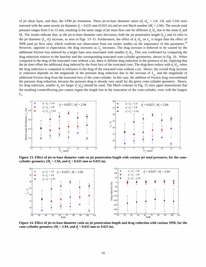
of jet shear layer, and thus, the LPM jet formation. Three jet-to-base diameter ratios (dj /d
m = 1/4, 1/8, and 1/16) were
assessed with the same nozzle jet diameter dj = 0.635 mm (0.025 in) and jet exit Mach number (M
j = 2.94). The nozzle total
pressure ranges from 5 to 15 atm, resulting in the same range of jet mass flow rate for different dj /d
m due to the same d
j and
Mj. The results indicate that, as the jet-to-base diameter ratio decreases, both the jet penetration length (L
p) and its ratio to
the jet diameter (Lp /dj
) increase, as seen in Figs. 13–15. Furthermore, the effect of dj /d
m on L
p is larger than the effect of
NPR (and jet flow rate), which confirms our observation from our earlier studies on the importance of this parameter.24
However, opposite to expectation, the drag increases as Lp increases. The drag increase is believed to be caused by the
additional friction loss induced by a larger base area associated with smaller dj /d
m. This was confirmed by comparing the
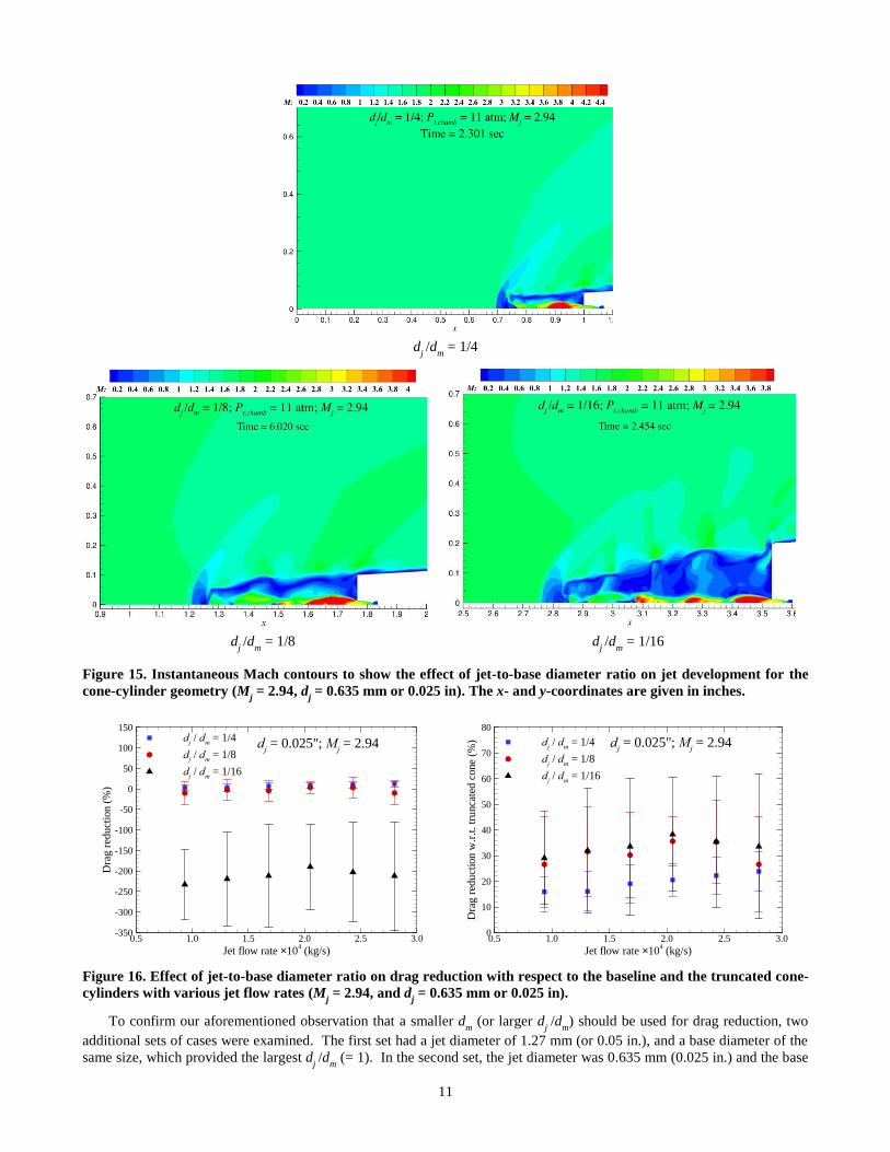
drag-reduction relative to the baseline and the corresponding truncated cone-cylinder geometries, shown in Fig. 16. When
compared to the drag of the truncated cone without a jet, there is definite drag reduction in the presence of jet, implying that
the jet does offset the additional drag induced by the front face of the truncated cone. The drag does reduce with dj /d
m, when
the drag reduction is computed in reference to the drag of the truncated cone without a jet. Hence, the overall drag increase
or reduction depends on the magnitude of the pressure drag reduction due to the increase of Lp, and the magnitude of
additional friction drag from the truncated face of the cone-cylinder. In this case, the addition of friction drag overwhelmed
the pressure drag reduction, because the pressure drag is already very small for the given cone-cylinder geometry. Hence,
for drag reduction, smaller dm (or larger d
j /d
m) should be used. The Mach contours in Fig. 15 once again demonstrate that
the resulting counterflowing jets cannot regain the length lost in the truncation of the cone-cylinder, even with the longest
Lp.
Figure 13. Effect of jet-to-base diameter ratio on jet penetration length with various jet total pressures, for the cone-
cylinder geometry (Mj = 2.94, and d
j = 0.635 mm or 0.025 in).
Figure 14. Effect of jet-to-base diameter ratio on jet penetration length and drag reduction with various NPR, for the
cone-cylinder geometry (Mj = 2.94, and d
j = 0.635 mm or 0.025 in).
Pt, j
(atm)
Shock
sta
nd
-off
dis
tance
, L
p (
in)
3 5 7 9 11 13 15 170
0.2
0.4
0.6
0.8
1d
j / d
m = 1/4
dj / d
m = 1/8
dj / d
m = 1/16
dj = 0.025"; M
j = 2.94
Pt, j
(atm)
Lp /
dj
3 5 7 9 11 13 15 175
10
15
20
25
30
35
40d
j / d
m = 1/4
dj / d
m = 1/8
dj / d
m = 1/16
dj = 0.025"; M
j = 2.94
NPR
Lp /
dj
20 30 40 50 60 70 80 90 100 1105
10
15
20
25
30
35
40
dj / d
m = 1/4
dj / d
m = 1/8
dj / d
m = 1/16
dj = 0.025"; M
j = 2.94
NPR
Dra
g r
edu
ctio
n (
%)
20 30 40 50 60 70 80 90 100 110-350
-300
-250
-200
-150
-100
-50
0
50
100
150d
j / d
m = 1/4
dj / d
m = 1/8
dj / d
m = 1/16
dj = 0.025"; M
j = 2.94
11
d
j /d
m = 1/4
d
j /d
m = 1/8 d
j /d
m = 1/16
Figure 15. Instantaneous Mach contours to show the effect of jet-to-base diameter ratio on jet development for the
cone-cylinder geometry (Mj = 2.94, d
j = 0.635 mm or 0.025 in). The x- and y-coordinates are given in inches.
Figure 16. Effect of jet-to-base diameter ratio on drag reduction with respect to the baseline and the truncated cone-
cylinders with various jet flow rates (Mj = 2.94, and d
j = 0.635 mm or 0.025 in).
To confirm our aforementioned observation that a smaller dm (or larger d
j /d
m) should be used for drag reduction, two
additional sets of cases were examined. The first set had a jet diameter of 1.27 mm (or 0.05 in.), and a base diameter of the
same size, which provided the largest dj /d
m (= 1). In the second set, the jet diameter was 0.635 mm (0.025 in.) and the base
Jet flow rate ´104 (kg/s)
Dra
g r
edu
ctio
n (
%)
0.5 1.0 1.5 2.0 2.5 3.0-350
-300
-250
-200
-150
-100
-50
0
50
100
150d
j / d
m = 1/4
dj / d
m = 1/8
dj / d
m = 1/16
dj = 0.025"; M
j = 2.94
Jet flow rate ´104 (kg/s)
Dra
g r
edu
ctio
n w
.r.t
. tr
unca
ted c
one
(%)
0.5 1.0 1.5 2.0 2.5 3.00
10
20
30
40
50
60
70
80
dj / d
m = 1/4
dj / d
m = 1/8
dj / d
m = 1/16
dj = 0.025"; M
j = 2.94
12
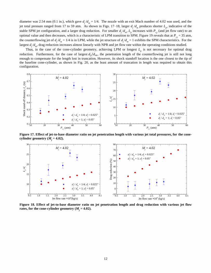
diameter was 2.54 mm (0.1 in.), which gave dj /d
m = 1/4. The nozzle with an exit Mach number of 4.02 was used, and the
jet total pressure ranged from 17 to 59 atm. As shown in Figs. 17–18, larger dj /d
m produces shorter L
p, indicative of the
stable SPM jet configuration, and a larger drag reduction. For smaller dj /d
m, L
p increases with P
t,j (and jet flow rate) to an
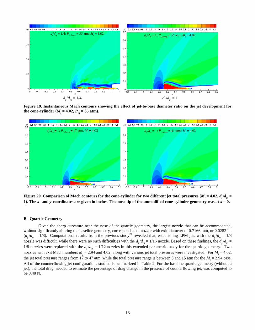
optimal value and then decreases, which is a characteristic of LPM transition to SPM. Figure 19 reveals that at Pt,j
= 35 atm,
the counterflowing jet of dj /d
m = 1/4 is in LPM, while the jet structure of d
j /d
m = 1 exhibits the SPM characteristics. For the
largest dj /d
m, drag reduction increases almost linearly with NPR and jet flow rate within the operating conditions studied.
Thus, in the case of the cone-cylinder geometry, achieving LPM or longest Lp is not necessary for optimal drag
reduction. Furthermore, for the case of largest 𝑑𝑗/𝑑𝑚, the penetration length of the counterflowing jet is still not long
enough to compensate for the length lost in truncation. However, its shock standoff location is the one closest to the tip of
the baseline cone-cylinder, as shown in Fig. 20, as the least amount of truncation in length was required to obtain this
configuration.
Figure 17. Effect of jet-to-base diameter ratio on jet penetration length with various jet total pressures, for the cone-
cylinder geometry (Mj = 4.02).
Figure 18. Effect of jet-to-base diameter ratio on jet penetration length and drag reduction with various jet flow
rates, for the cone-cylinder geometry (Mj = 4.02).
Pt, j
(atm)
Shock
sta
nd
-off
dis
tance
, L
p (
in)
10 20 30 40 50 600.1
0.2
0.3
0.4
0.5
0.6
0.7
0.8
dj / d
m = 1/4; d
j = 0.025"
dj / d
m = 1; d
j = 0.05"
Mj = 4.02
Pt, j
(atm)
Lp
/dj
10 20 30 40 50 600
5
10
15
20
25
30
dj / d
m = 1/4; d
j = 0.025"
dj / d
m = 1; d
j = 0.05"
Mj = 4.02
Jet flow rate ´104(kg/s)
Lp
/dj
0.5 1.0 1.5 2.0 2.5 3.0 3.5 4.0 4.55
10
15
20
25
30
dj / d
m = 1/4; d
j = 0.025"
dj / d
m = 1; d
j = 0.05"
Mj = 4.02
Jet flow rate ´104 (kg/s)
Dra
g r
edu
ctio
n (
%)
0.5 1.0 1.5 2.0 2.5 3.0 3.5 4.0 4.5-10
0
10
20
30
40
50
60
70
80
dj / d
m = 1/4; d
j = 0.025"
dj / d
m = 1; d
j = 0.05"
Mj = 4.02
13
d
j /d
m = 1/4 d
j /d
m = 1
Figure 19. Instantaneous Mach contours showing the effect of jet-to-base diameter ratio on the jet development for
the cone-cylinder (Mj = 4.02, P
t,j = 35 atm).
Figure 20. Comparison of Mach contours for the cone-cylinder for two different jet total pressures (Mj = 4.02, d
j /d
m =
1). The x- and y-coordinates are given in inches. The nose tip of the unmodified cone-cylinder geometry was at x = 0.
B. Quartic Geometry
Given the sharp curvature near the nose of the quartic geometry, the largest nozzle that can be accommodated,
without significantly altering the baseline geometry, corresponds to a nozzle with exit diameter of 0.7166 mm, or 0.0282 in.
(dj /d
m = 1/8). Computational results from the previous study
24 revealed that, establishing LPM jets with the d
j /d
m = 1/8
nozzle was difficult, while there were no such difficulties with the dj /d
m = 1/16 nozzle. Based on these findings, the d
j /d
m =
1/8 nozzles were replaced with the dj /d
m = 1/12 nozzles in this extended parametric study for the quartic geometry. Two
nozzles with exit Mach numbers Mj = 2.94 and 4.02, along with various jet total pressures were investigated. For M
j = 4.02,
the jet total pressure ranges from 17 to 47 atm, while the total pressure range is between 3 and 15 atm for the Mj = 2.94 case.
All of the counterflowing jet configurations studied is summarized in Table 2. For the baseline quartic geometry (without a
jet), the total drag, needed to estimate the percentage of drag change in the presence of counterflowing jet, was computed to
be 0.48 N.
14
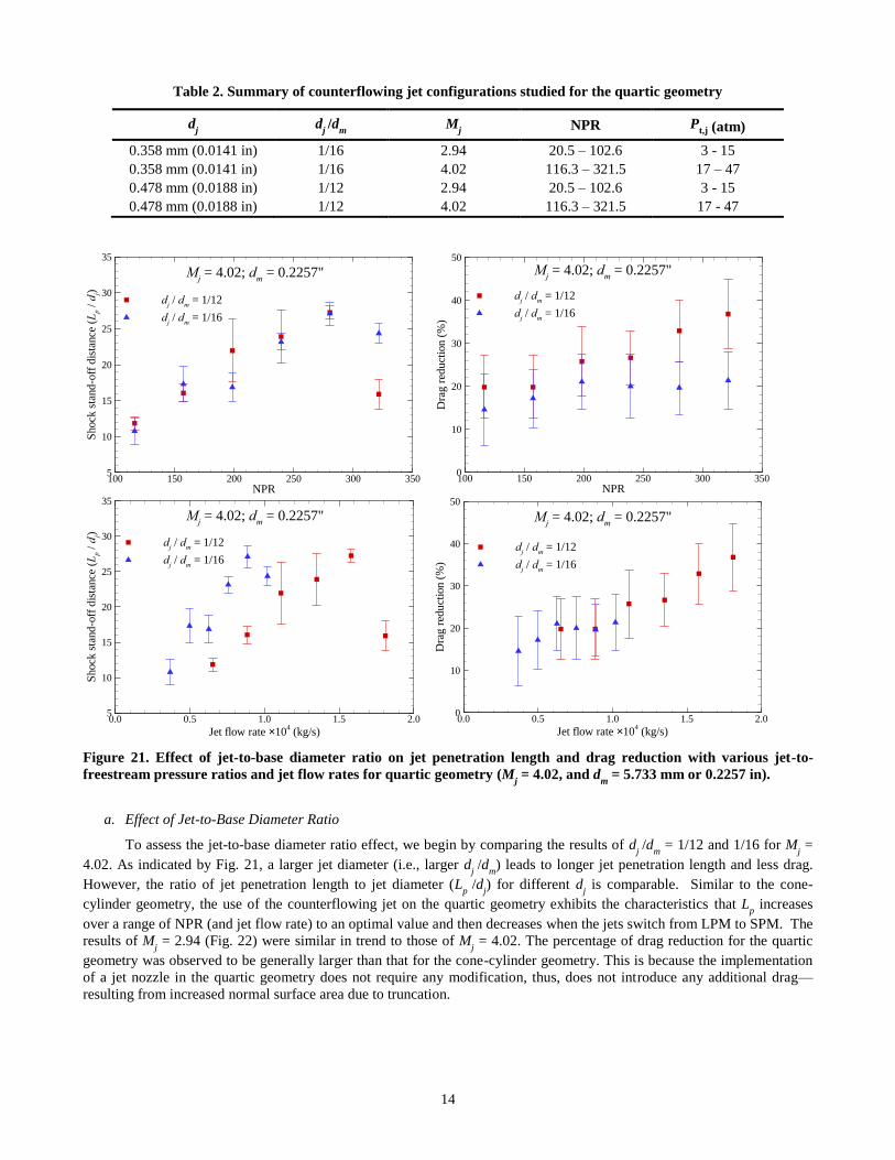
Table 2. Summary of counterflowing jet configurations studied for the quartic geometry
dj d
j /d
m M
j NPR P
t,j (atm)
0.358 mm (0.0141 in) 1/16 2.94 20.5 – 102.6 3 - 15
0.358 mm (0.0141 in) 1/16 4.02 116.3 – 321.5 17 – 47
0.478 mm (0.0188 in) 1/12 2.94 20.5 – 102.6 3 - 15
0.478 mm (0.0188 in) 1/12 4.02 116.3 – 321.5 17 - 47
Figure 21. Effect of jet-to-base diameter ratio on jet penetration length and drag reduction with various jet-to-
freestream pressure ratios and jet flow rates for quartic geometry (Mj = 4.02, and d
m = 5.733 mm or 0.2257 in).
a. Effect of Jet-to-Base Diameter Ratio
To assess the jet-to-base diameter ratio effect, we begin by comparing the results of dj /d
m = 1/12 and 1/16 for M
j =
4.02. As indicated by Fig. 21, a larger jet diameter (i.e., larger dj /d
m) leads to longer jet penetration length and less drag.
However, the ratio of jet penetration length to jet diameter (Lp /dj
) for different dj is comparable. Similar to the cone-
cylinder geometry, the use of the counterflowing jet on the quartic geometry exhibits the characteristics that Lp increases
over a range of NPR (and jet flow rate) to an optimal value and then decreases when the jets switch from LPM to SPM. The
results of Mj = 2.94 (Fig. 22) were similar in trend to those of M
j = 4.02. The percentage of drag reduction for the quartic
geometry was observed to be generally larger than that for the cone-cylinder geometry. This is because the implementation
of a jet nozzle in the quartic geometry does not require any modification, thus, does not introduce any additional drag—
resulting from increased normal surface area due to truncation.
NPR
Shock
sta
nd-o
ff d
ista
nce
(L
p /
dj)
100 150 200 250 300 3505
10
15
20
25
30
35
dj / d
m = 1/12
dj / d
m = 1/16
Mj = 4.02; d
m = 0.2257"
NPR
Dra
g r
edu
ctio
n (
%)
100 150 200 250 300 3500
10
20
30
40
50
dj / d
m = 1/12
dj / d
m = 1/16
Mj = 4.02; d
m = 0.2257"
Jet flow rate ´104 (kg/s)
Shock
sta
nd
-off
dis
tance
(L
p /
dj)
0.0 0.5 1.0 1.5 2.05
10
15
20
25
30
35
dj / d
m = 1/12
dj / d
m = 1/16
Mj = 4.02; d
m = 0.2257"
Jet flow rate ´104 (kg/s)
Dra
g r
edu
ctio
n (
%)
0.0 0.5 1.0 1.5 2.00
10
20
30
40
50
dj / d
m = 1/12
dj / d
m = 1/16
Mj = 4.02; d
m = 0.2257"
15
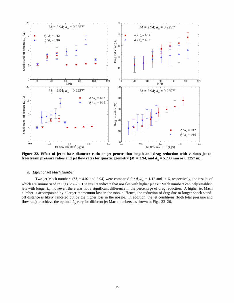
Figure 22. Effect of jet-to-base diameter ratio on jet penetration length and drag reduction with various jet-to-
freestream pressure ratios and jet flow rates for quartic geometry (Mj = 2.94, and d
m = 5.733 mm or 0.2257 in).
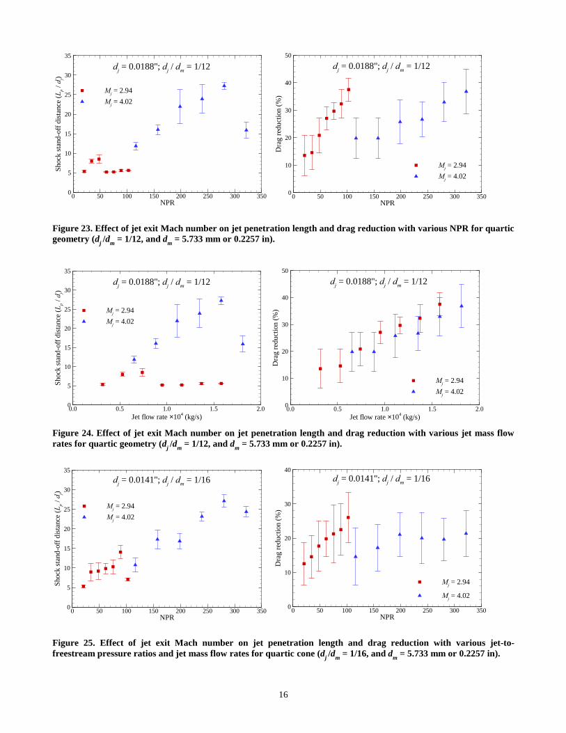
b. Effect of Jet Mach Number
Two jet Mach numbers (Mj = 4.02 and 2.94) were compared for d
j /d
m = 1/12 and 1/16, respectively, the results of
which are summarized in Figs. 23–26. The results indicate that nozzles with higher jet exit Mach numbers can help establish
jets with longer Lp; however, there was not a significant difference in the percentage of drag reduction. A higher jet Mach
number is accompanied by a larger momentum loss in the nozzle. Hence, the reduction of drag due to longer shock stand-
off distance is likely canceled out by the higher loss in the nozzle. In addition, the jet conditions (both total pressure and
flow rate) to achieve the optimal Lp vary for different jet Mach numbers, as shown in Figs. 23–26.
NPR
Shock
sta
nd
-off
dis
tance
(L
p /
dj)
20 40 60 80 100 1200
5
10
15
20
dj / d
m = 1/12
dj / d
m = 1/16
Mj = 2.94; d
m = 0.2257"
NPR
Dra
g r
edu
ctio
n (
%)
0 20 40 60 80 100 1200
10
20
30
40
50
dj / d
m = 1/12
dj / d
m = 1/16
Mj = 2.94; d
m = 0.2257"
Jet flow rate ´104 (kg/s)
Shock
sta
nd
-off
dis
tance
(L
p /
dj)
0.0 0.5 1.0 1.5 2.00
5
10
15
20
dj / d
m = 1/12
dj / d
m = 1/16
Mj = 2.94; d
m = 0.2257"
Jet flow rate ´104 (kg/s)
Dra
g r
edu
ctio
n (
%)
0.0 0.5 1.0 1.5 2.00
10
20
30
40
50
dj / d
m = 1/12
dj / d
m = 1/16
Mj = 2.94; d
m = 0.2257"
16
Figure 23. Effect of jet exit Mach number on jet penetration length and drag reduction with various NPR for quartic
geometry (dj /d
m = 1/12, and d
m = 5.733 mm or 0.2257 in).
Figure 24. Effect of jet exit Mach number on jet penetration length and drag reduction with various jet mass flow
rates for quartic geometry (dj /d
m = 1/12, and d
m = 5.733 mm or 0.2257 in).
Figure 25. Effect of jet exit Mach number on jet penetration length and drag reduction with various jet-to-
freestream pressure ratios and jet mass flow rates for quartic cone (dj /d
m = 1/16, and d
m = 5.733 mm or 0.2257 in).
NPR
Shock
sta
nd
-off
dis
tance
(L
p /
dj)
0 50 100 150 200 250 300 3500
5
10
15
20
25
30
35
Mj = 2.94
Mj = 4.02
dj = 0.0188"; d
j / d
m = 1/12
NPR
Dra
g r
edu
ctio
n (
%)
0 50 100 150 200 250 300 3500
10
20
30
40
50
Mj = 2.94
Mj = 4.02
dj = 0.0188"; d
j / d
m = 1/12
Jet flow rate ´104 (kg/s)
Shock
sta
nd
-off
dis
tance
(L
p /
dj)
0.0 0.5 1.0 1.5 2.00
5
10
15
20
25
30
35
Mj = 2.94
Mj = 4.02
dj = 0.0188"; d
j / d
m = 1/12
Jet flow rate ´104 (kg/s)
Dra
g r
edu
ctio
n (
%)
0.0 0.5 1.0 1.5 2.00
10
20
30
40
50
Mj = 2.94
Mj = 4.02
dj = 0.0188"; d
j / d
m = 1/12
NPR
Shock
sta
nd
-off
dis
tance
(L
p /
dj)
0 50 100 150 200 250 300 3500
5
10
15
20
25
30
35
Mj = 2.94
Mj = 4.02
dj = 0.0141"; d
j / d
m = 1/16
NPR
Dra
g r
edu
ctio
n (
%)
0 50 100 150 200 250 300 3500
10
20
30
40
Mj = 2.94
Mj = 4.02
dj = 0.0141"; d
j / d
m = 1/16
17
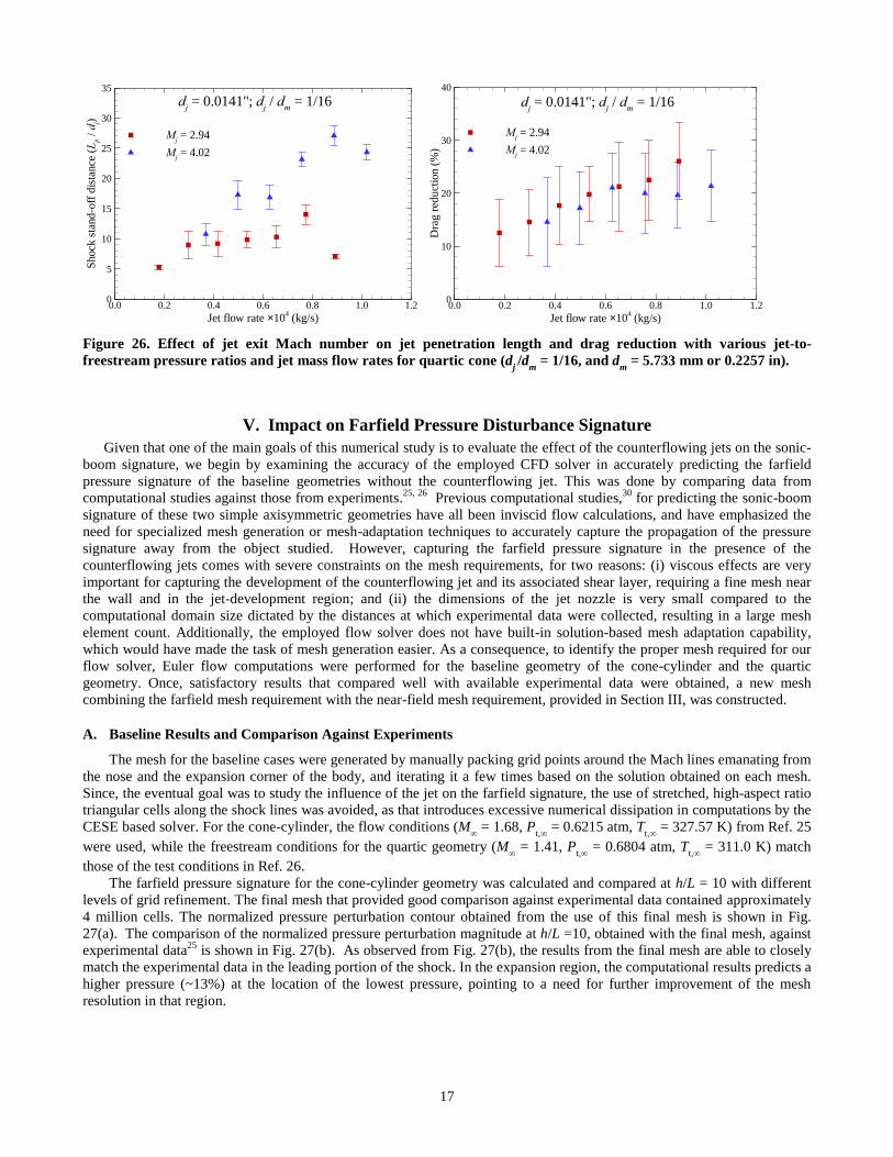
Figure 26. Effect of jet exit Mach number on jet penetration length and drag reduction with various jet-to-
freestream pressure ratios and jet mass flow rates for quartic cone (dj /d
m = 1/16, and d
m = 5.733 mm or 0.2257 in).
V. Impact on Farfield Pressure Disturbance Signature
Given that one of the main goals of this numerical study is to evaluate the effect of the counterflowing jets on the sonic-
boom signature, we begin by examining the accuracy of the employed CFD solver in accurately predicting the farfield
pressure signature of the baseline geometries without the counterflowing jet. This was done by comparing data from
computational studies against those from experiments.25, 26
Previous computational studies,30
for predicting the sonic-boom
signature of these two simple axisymmetric geometries have all been inviscid flow calculations, and have emphasized the
need for specialized mesh generation or mesh-adaptation techniques to accurately capture the propagation of the pressure
signature away from the object studied. However, capturing the farfield pressure signature in the presence of the
counterflowing jets comes with severe constraints on the mesh requirements, for two reasons: (i) viscous effects are very
important for capturing the development of the counterflowing jet and its associated shear layer, requiring a fine mesh near
the wall and in the jet-development region; and (ii) the dimensions of the jet nozzle is very small compared to the
computational domain size dictated by the distances at which experimental data were collected, resulting in a large mesh
element count. Additionally, the employed flow solver does not have built-in solution-based mesh adaptation capability,
which would have made the task of mesh generation easier. As a consequence, to identify the proper mesh required for our
flow solver, Euler flow computations were performed for the baseline geometry of the cone-cylinder and the quartic
geometry. Once, satisfactory results that compared well with available experimental data were obtained, a new mesh
combining the farfield mesh requirement with the near-field mesh requirement, provided in Section III, was constructed.
A. Baseline Results and Comparison Against Experiments
The mesh for the baseline cases were generated by manually packing grid points around the Mach lines emanating from
the nose and the expansion corner of the body, and iterating it a few times based on the solution obtained on each mesh.
Since, the eventual goal was to study the influence of the jet on the farfield signature, the use of stretched, high-aspect ratio
triangular cells along the shock lines was avoided, as that introduces excessive numerical dissipation in computations by the
CESE based solver. For the cone-cylinder, the flow conditions (M∞ = 1.68, P
t,∞ = 0.6215 atm, T
t,∞ = 327.57 K) from Ref. 25
were used, while the freestream conditions for the quartic geometry (M∞ = 1.41, P
t,∞ = 0.6804 atm, T
t,∞ = 311.0 K) match
those of the test conditions in Ref. 26.
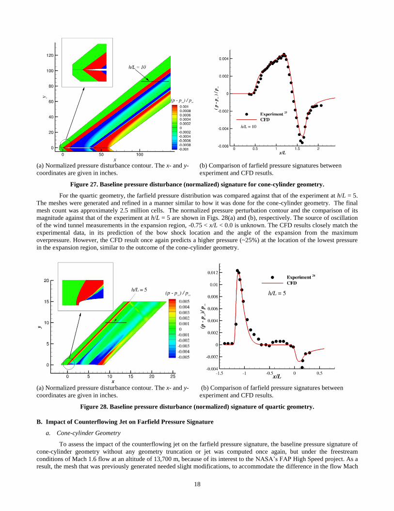
The farfield pressure signature for the cone-cylinder geometry was calculated and compared at h/L = 10 with different
levels of grid refinement. The final mesh that provided good comparison against experimental data contained approximately
4 million cells. The normalized pressure perturbation contour obtained from the use of this final mesh is shown in Fig.
27(a). The comparison of the normalized pressure perturbation magnitude at h/L =10, obtained with the final mesh, against
experimental data25
is shown in Fig. 27(b). As observed from Fig. 27(b), the results from the final mesh are able to closely
match the experimental data in the leading portion of the shock. In the expansion region, the computational results predicts a
higher pressure (~13%) at the location of the lowest pressure, pointing to a need for further improvement of the mesh
resolution in that region.
Jet flow rate ´104 (kg/s)
Shock
sta
nd
-off
dis
tance
(L
p /
dj)
0.0 0.2 0.4 0.6 0.8 1.0 1.20
5
10
15
20
25
30
35
Mj = 2.94
Mj = 4.02
dj = 0.0141"; d
j / d
m = 1/16
Jet flow rate ´104 (kg/s)
Dra
g r
edu
ctio
n (
%)
0.0 0.2 0.4 0.6 0.8 1.0 1.20
10
20
30
40
Mj = 2.94
Mj = 4.02
dj = 0.0141"; d
j / d
m = 1/16
18
(a) Normalized pressure disturbance contour. The x- and y-
coordinates are given in inches.
(b) Comparison of farfield pressure signatures between
experiment and CFD resutls.
Figure 27. Baseline pressure disturbance (normalized) signature for cone-cylinder geometry.
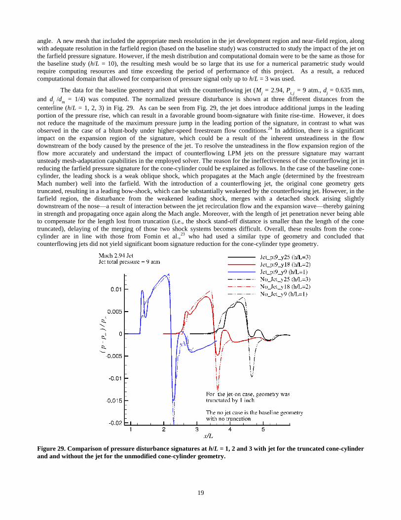
For the quartic geometry, the farfield pressure distribution was compared against that of the experiment at h/L = 5.
The meshes were generated and refined in a manner similar to how it was done for the cone-cylinder geometry. The final
mesh count was approximately 2.5 million cells. The normalized pressure perturbation contour and the comparison of its
magnitude against that of the experiment at h/L = 5 are shown in Figs. 28(a) and (b), respectively. The source of oscillation
of the wind tunnel measurements in the expansion region, -0.75 < x/L < 0.0 is unknown. The CFD results closely match the
experimental data, in its prediction of the bow shock location and the angle of the expansion from the maximum
overpressure. However, the CFD result once again predicts a higher pressure (~25%) at the location of the lowest pressure
in the expansion region, similar to the outcome of the cone-cylinder geometry.
(a) Normalized pressure disturbance contour. The x- and y-
coordinates are given in inches. (b) Comparison of farfield pressure signatures between
experiment and CFD results.
Figure 28. Baseline pressure disturbance (normalized) signature of quartic geometry.
B. Impact of Counterflowing Jet on Farfield Pressure Signature
a. Cone-cylinder Geometry
To assess the impact of the counterflowing jet on the farfield pressure signature, the baseline pressure signature of
cone-cylinder geometry without any geometry truncation or jet was computed once again, but under the freestream
conditions of Mach 1.6 flow at an altitude of 13,700 m, because of its interest to the NASA’s FAP High Speed project. As a
result, the mesh that was previously generated needed slight modifications, to accommodate the difference in the flow Mach
19
angle. A new mesh that included the appropriate mesh resolution in the jet development region and near-field region, along
with adequate resolution in the farfield region (based on the baseline study) was constructed to study the impact of the jet on
the farfield pressure signature. However, if the mesh distribution and computational domain were to be the same as those for
the baseline study (h/L = 10), the resulting mesh would be so large that its use for a numerical parametric study would
require computing resources and time exceeding the period of performance of this project. As a result, a reduced
computational domain that allowed for comparison of pressure signal only up to h/L = 3 was used.
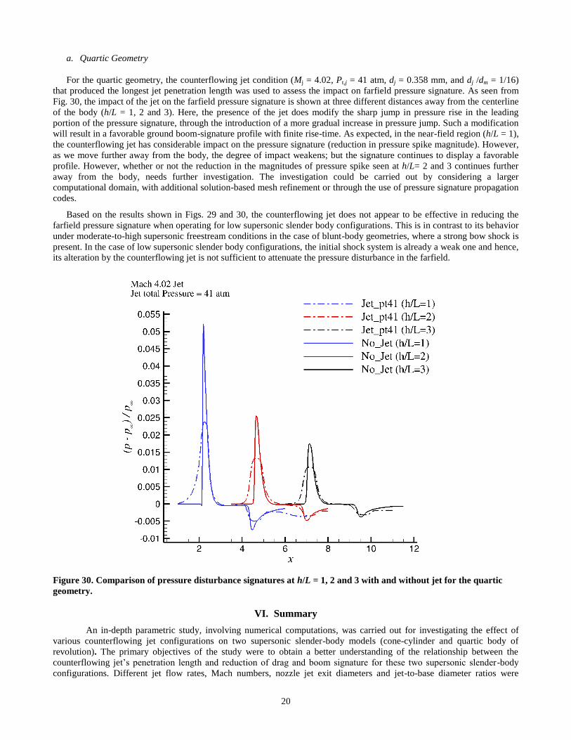
The data for the baseline geometry and that with the counterflowing jet (Mj = 2.94, P
t, j = 9 atm., d
j = 0.635 mm,
and dj
/dm = 1/4) was computed. The normalized pressure disturbance is shown at three different distances from the
centerline (h/L = 1, 2, 3) in Fig. 29. As can be seen from Fig. 29, the jet does introduce additional jumps in the leading
portion of the pressure rise, which can result in a favorable ground boom-signature with finite rise-time. However, it does
not reduce the magnitude of the maximum pressure jump in the leading portion of the signature, in contrast to what was
observed in the case of a blunt-body under higher-speed freestream flow conditions.24
In addition, there is a significant
impact on the expansion region of the signature, which could be a result of the inherent unsteadiness in the flow
downstream of the body caused by the presence of the jet. To resolve the unsteadiness in the flow expansion region of the
flow more accurately and understand the impact of counterflowing LPM jets on the pressure signature may warrant
unsteady mesh-adaptation capabilities in the employed solver. The reason for the ineffectiveness of the counterflowing jet in
reducing the farfield pressure signature for the cone-cylinder could be explained as follows. In the case of the baseline cone-
cylinder, the leading shock is a weak oblique shock, which propagates at the Mach angle (determined by the freestream
Mach number) well into the farfield. With the introduction of a counterflowing jet, the original cone geometry gets
truncated, resulting in a leading bow-shock, which can be substantially weakened by the counterflowing jet. However, in the
farfield region, the disturbance from the weakened leading shock, merges with a detached shock arising slightly
downstream of the nose—a result of interaction between the jet recirculation flow and the expansion wave—thereby gaining
in strength and propagating once again along the Mach angle. Moreover, with the length of jet penetration never being able
to compensate for the length lost from truncation (i.e., the shock stand-off distance is smaller than the length of the cone
truncated), delaying of the merging of those two shock systems becomes difficult. Overall, these results from the cone-
cylinder are in line with those from Fomin et al.,23
who had used a similar type of geometry and concluded that
counterflowing jets did not yield significant boom signature reduction for the cone-cylinder type geometry.
Figure 29. Comparison of pressure disturbance signatures at h/L = 1, 2 and 3 with jet for the truncated cone-cylinder
and and without the jet for the unmodified cone-cylinder geometry.
20
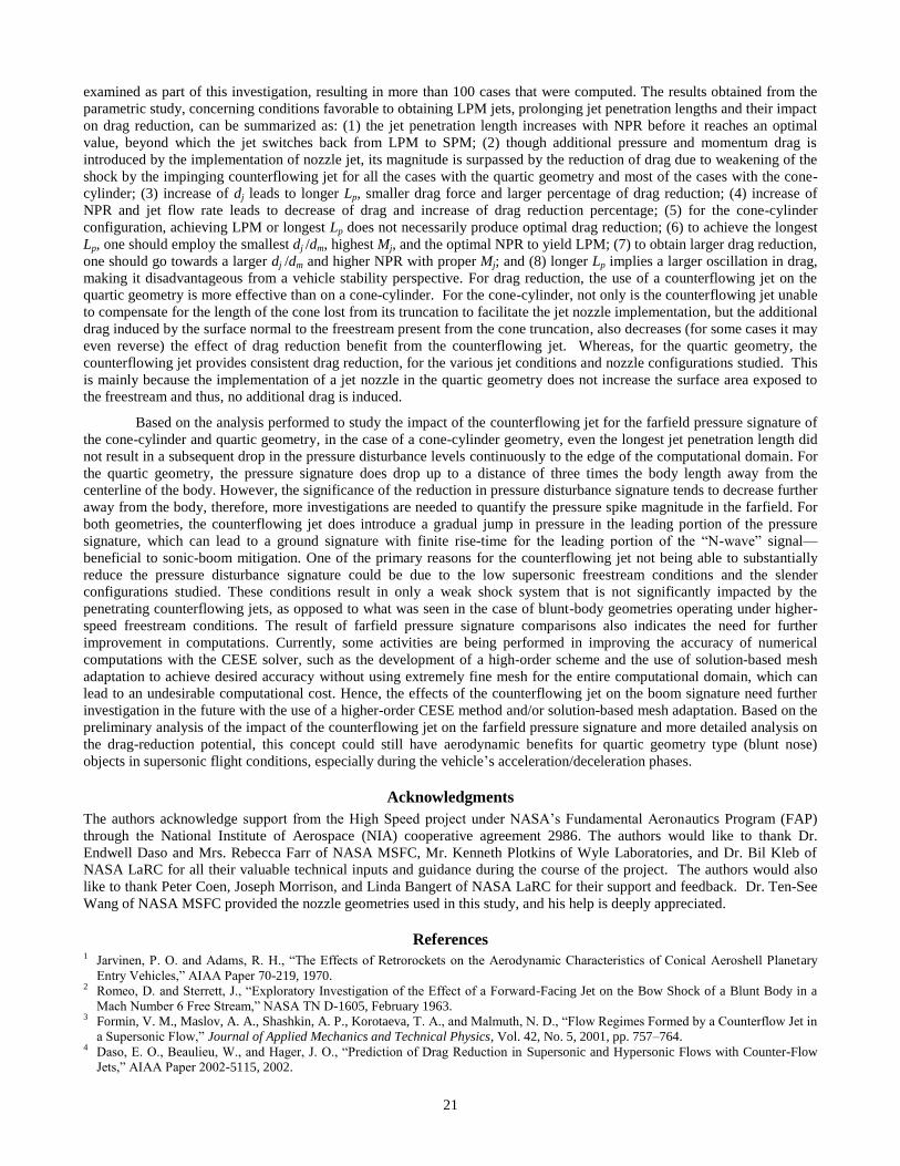
a. Quartic Geometry
For the quartic geometry, the counterflowing jet condition (Mj = 4.02, Pt,j = 41 atm, dj = 0.358 mm, and dj /dm = 1/16)
that produced the longest jet penetration length was used to assess the impact on farfield pressure signature. As seen from
Fig. 30, the impact of the jet on the farfield pressure signature is shown at three different distances away from the centerline
of the body (h/L = 1, 2 and 3). Here, the presence of the jet does modify the sharp jump in pressure rise in the leading
portion of the pressure signature, through the introduction of a more gradual increase in pressure jump. Such a modification
will result in a favorable ground boom-signature profile with finite rise-time. As expected, in the near-field region (h/L = 1),
the counterflowing jet has considerable impact on the pressure signature (reduction in pressure spike magnitude). However,
as we move further away from the body, the degree of impact weakens; but the signature continues to display a favorable
profile. However, whether or not the reduction in the magnitudes of pressure spike seen at h/L= 2 and 3 continues further
away from the body, needs further investigation. The investigation could be carried out by considering a larger
computational domain, with additional solution-based mesh refinement or through the use of pressure signature propagation
codes.
Based on the results shown in Figs. 29 and 30, the counterflowing jet does not appear to be effective in reducing the
farfield pressure signature when operating for low supersonic slender body configurations. This is in contrast to its behavior
under moderate-to-high supersonic freestream conditions in the case of blunt-body geometries, where a strong bow shock is
present. In the case of low supersonic slender body configurations, the initial shock system is already a weak one and hence,
its alteration by the counterflowing jet is not sufficient to attenuate the pressure disturbance in the farfield.
Figure 30. Comparison of pressure disturbance signatures at h/L = 1, 2 and 3 with and without jet for the quartic
geometry.
VI. Summary
An in-depth parametric study, involving numerical computations, was carried out for investigating the effect of
various counterflowing jet configurations on two supersonic slender-body models (cone-cylinder and quartic body of
revolution). The primary objectives of the study were to obtain a better understanding of the relationship between the
counterflowing jet’s penetration length and reduction of drag and boom signature for these two supersonic slender-body
configurations. Different jet flow rates, Mach numbers, nozzle jet exit diameters and jet-to-base diameter ratios were
21
examined as part of this investigation, resulting in more than 100 cases that were computed. The results obtained from the
parametric study, concerning conditions favorable to obtaining LPM jets, prolonging jet penetration lengths and their impact
on drag reduction, can be summarized as: (1) the jet penetration length increases with NPR before it reaches an optimal
value, beyond which the jet switches back from LPM to SPM; (2) though additional pressure and momentum drag is
introduced by the implementation of nozzle jet, its magnitude is surpassed by the reduction of drag due to weakening of the
shock by the impinging counterflowing jet for all the cases with the quartic geometry and most of the cases with the cone-
cylinder; (3) increase of dj leads to longer Lp, smaller drag force and larger percentage of drag reduction; (4) increase of
NPR and jet flow rate leads to decrease of drag and increase of drag reduction percentage; (5) for the cone-cylinder
configuration, achieving LPM or longest Lp does not necessarily produce optimal drag reduction; (6) to achieve the longest
Lp, one should employ the smallest dj /dm, highest Mj, and the optimal NPR to yield LPM; (7) to obtain larger drag reduction,
one should go towards a larger dj /dm and higher NPR with proper Mj; and (8) longer Lp implies a larger oscillation in drag,
making it disadvantageous from a vehicle stability perspective. For drag reduction, the use of a counterflowing jet on the
quartic geometry is more effective than on a cone-cylinder. For the cone-cylinder, not only is the counterflowing jet unable
to compensate for the length of the cone lost from its truncation to facilitate the jet nozzle implementation, but the additional
drag induced by the surface normal to the freestream present from the cone truncation, also decreases (for some cases it may
even reverse) the effect of drag reduction benefit from the counterflowing jet. Whereas, for the quartic geometry, the
counterflowing jet provides consistent drag reduction, for the various jet conditions and nozzle configurations studied. This
is mainly because the implementation of a jet nozzle in the quartic geometry does not increase the surface area exposed to
the freestream and thus, no additional drag is induced.
Based on the analysis performed to study the impact of the counterflowing jet for the farfield pressure signature of
the cone-cylinder and quartic geometry, in the case of a cone-cylinder geometry, even the longest jet penetration length did
not result in a subsequent drop in the pressure disturbance levels continuously to the edge of the computational domain. For
the quartic geometry, the pressure signature does drop up to a distance of three times the body length away from the
centerline of the body. However, the significance of the reduction in pressure disturbance signature tends to decrease further
away from the body, therefore, more investigations are needed to quantify the pressure spike magnitude in the farfield. For
both geometries, the counterflowing jet does introduce a gradual jump in pressure in the leading portion of the pressure
signature, which can lead to a ground signature with finite rise-time for the leading portion of the “N-wave” signal—
beneficial to sonic-boom mitigation. One of the primary reasons for the counterflowing jet not being able to substantially
reduce the pressure disturbance signature could be due to the low supersonic freestream conditions and the slender
configurations studied. These conditions result in only a weak shock system that is not significantly impacted by the
penetrating counterflowing jets, as opposed to what was seen in the case of blunt-body geometries operating under higher-
speed freestream conditions. The result of farfield pressure signature comparisons also indicates the need for further
improvement in computations. Currently, some activities are being performed in improving the accuracy of numerical
computations with the CESE solver, such as the development of a high-order scheme and the use of solution-based mesh
adaptation to achieve desired accuracy without using extremely fine mesh for the entire computational domain, which can
lead to an undesirable computational cost. Hence, the effects of the counterflowing jet on the boom signature need further
investigation in the future with the use of a higher-order CESE method and/or solution-based mesh adaptation. Based on the
preliminary analysis of the impact of the counterflowing jet on the farfield pressure signature and more detailed analysis on
the drag-reduction potential, this concept could still have aerodynamic benefits for quartic geometry type (blunt nose)
objects in supersonic flight conditions, especially during the vehicle’s acceleration/deceleration phases.
Acknowledgments
The authors acknowledge support from the High Speed project under NASA’s Fundamental Aeronautics Program (FAP)
through the National Institute of Aerospace (NIA) cooperative agreement 2986. The authors would like to thank Dr.
Endwell Daso and Mrs. Rebecca Farr of NASA MSFC, Mr. Kenneth Plotkins of Wyle Laboratories, and Dr. Bil Kleb of
NASA LaRC for all their valuable technical inputs and guidance during the course of the project. The authors would also
like to thank Peter Coen, Joseph Morrison, and Linda Bangert of NASA LaRC for their support and feedback. Dr. Ten-See
Wang of NASA MSFC provided the nozzle geometries used in this study, and his help is deeply appreciated.
References 1 Jarvinen, P. O. and Adams, R. H., “The Effects of Retrorockets on the Aerodynamic Characteristics of Conical Aeroshell Planetary
Entry Vehicles,” AIAA Paper 70-219, 1970. 2 Romeo, D. and Sterrett, J., “Exploratory Investigation of the Effect of a Forward-Facing Jet on the Bow Shock of a Blunt Body in a
Mach Number 6 Free Stream,” NASA TN D-1605, February 1963. 3 Formin, V. M., Maslov, A. A., Shashkin, A. P., Korotaeva, T. A., and Malmuth, N. D., “Flow Regimes Formed by a Counterflow Jet in
a Supersonic Flow,” Journal of Applied Mechanics and Technical Physics, Vol. 42, No. 5, 2001, pp. 757–764. 4 Daso, E. O., Beaulieu, W., and Hager, J. O., “Prediction of Drag Reduction in Supersonic and Hypersonic Flows with Counter-Flow
Jets,” AIAA Paper 2002-5115, 2002.
22
5 Daso, E. O., Pritchett, V. E., Wang, T. S., Ota, D. K., Blankson, I. M., and Auslender. A. H., “The Dynamics of Shock Dispersion and
Interactions in Supersonic Freestreams with Counterflowing Jets,” AIAA Journal, Vol. 47, No. 6, 2009, pp. 1313–1326. 6 Berry, S. A., Rhode, M. N., and Edquist, K. T., “Supersonic Retropropulsion Validation Experiment in the NASA Langley Unitary
Plan Wind Tunnel,” Journal of Spacecraft and Rockets, Vol. 51, No. 3, 2014, pp. 664–679. 7 Berry, S. A., Rhode, M. N., and Edquist, K. T., “Supersonic Retropropulsion Experimental Results from NASA Ames 9×7 Foot
Supersonic Wind Tunnel,” Journal of Spacecraft and Rockets, Vol. 51, No. 3, 2014, pp. 724–734. 8 Korzun, A. M., Braun, R. D., and Cruz, J. R., “Survey of Supersonic Retropropulsion Technology for Mars Entry, Descent, and
Landing,” Journal of Spacecraft and Rockets, Vol. 46, No. 5, 2009, pp. 929–937. 9 Chang, C-L., Venkatachari, B. S., and Cheng, G. C., “Effect of Counterflow Jet on a Supersonic Reentry Capsule,” AIAA Paper 2006-
4776, 2006. 10 Cheng, G. C., Neroorkar, K. D., Chen, Y-S., Wang, T-S., and Daso, E. O., “Numerical Study of Flow Augmented Thermal
Management for Entry and Re-entry Environments,” AIAA Paper 2007-4560, 2007. 11 Korzun, A. M., Cordell, Jr., C. E., and Braun, R. D., “Comparison of Inviscid and Viscous Aerodynamic Predictions of Supersonic
Retropropulsion Flowfields,” AIAA Paper 2010-5048, 2010. 12 Trumble, K. A., Schauerhamer, D. G., Kleb, W. L., Carlson, J-R., Buning, P. G., Edquist, K. T., and Barnhardt, M. D., “An Initial
Assessment of Navier-Stokes Codes Applied to Supersonic Retro-Propulsion,” AIAA Paper 2010-5047, 2010. 13 Kleb, W. L., Schauerhamer, G. D., Trumble, K. A., Sozer, E., Barnhardt, M. D., Carlson, J-R., and Edquist, K. T., “Toward Supersonic
Retropropulsion CFD Validation,” AIAA Paper 2011-3490, 2011. 14 Venkatachari, B. S., Ito, Y., Cheng, G. C., and Chang, C.-L., “Numerical Investigation of the Interaction of Counterflowing Jets and
Supersonic Capsule Flows,” AIAA Paper 2011-4030, 2011. 15 Plotkin, K. J. and Maglieri, D. J., “Sonic Boom Research: History and Future,” AIAA Paper 2003-3575, 2003. 16 Whitham, G. B., “The Flow Pattern of a Supersonic Projectile,” Communications on Pure and Applied Mathematics, Vol. 5, No. 3,
1952, pp. 301–348. 17 Walkden, F., “The Shock Pattern of a Wing-body Combination, Far from the Flight Path,” Aeronautical Quarterly, Vol. IX, Pt. 2,
1958, pp. 164–194. 18 George, A. R., “Reduction of Sonic Boom by Azimuthal Redistribution of Overpressure,” AIAA Journal, Vol. 7, 1969, pp. 291–298. 19 Hayes, W. D., Haefeli, R. C., and Kulsrud, H. E., “Sonic Boom Propagation in a Stratified Atmosphere, With Computer Program,”
NASA CR-1299, 1969. 20 Crow, S. C., “Distortion of Sonic Bangs by Atmospheric Turbulence,” Journal of Fluid Mechanics, Vol. 37, 1969, pp. 529–56. 21 Plotkin, K. J., and George, A. R., “Propagation of Weak Shock Waves Through Turbulence,” Journal of Fluid Mechanics, Vol. 54,
1972, pp. 449–467. 22 Miller, D. S., and Carlson, H. W., “A Study of the Application of Heat or Force Fields to the Sonic-boom-minimization Problem,”
NASA TN D-5582, 1969. 23 Fomin, V. M., Chirkashenko, V. F., and Volkov, V. F., “The Sonic-Boom Problem and Possible Ways Towards its Solution,” 14th
International Conference on Methods of Aerophyiscal Research (ICMAR), Russia, 2008. 24 Venkatachari, B. S., Cheng, G. C., Chang, C.-L., Zichettello, B., and Bilyeu, D. L., “Long Penetration Mode Counterflowing Jets for
Supersonic Slender Configurations—A Numerical Study,” AIAA Paper 2013-2662, 2013. 25 Mendoza, J. P. and Hicks, R. M., “Further Studies of the Extrapolation of Near-Field Overpressure Data,” NASA TM X-2219, 1971. 26 Carlson, H. W., Mack, R. J., and Morris, O. A., “A Wind-tunnel Investigation of the Effect of Body Shape on Sonic-boom Pressure
Distribution,” NASA TN D-3106, 1965. 27 Chang, S.-C., “The Method of Space-Time Conservation Element and Solution Element—A New Approach for Solving the Navier-
Stokes and Euler Equations,” Journal of Computational Physics, Vol. 119, 1995, pp. 295–324. 28 Chang, S.-C., Wang, X.-Y., and To, W.-M., “Application of the Space-Time Conservation Element and Solution Element Method to
One-Dimensional Convection-Diffusion Problems,” Journal of Computational Physics, Vol. 165, 2000, pp. 189–215. 29 Chang, C.-L., “Three-Dimensional Navier-Stokes Calculations Using the Modified Space-Time CESE Method,” AIAA Paper 2007-
5818, 2007. 30 Park, M. A., Aftosmis, M. J., Campbell, R. L., Carter, M. B., Cliff, S. E., and Bangert, L. S., “Summary of the 2008 Fundamental
Aeronautics Program Sonic Boom Prediction Workshop,” Journal of Aircraft, Vol. 51, No. 3, pp. 987–1001, 2014. 31 Chang, C.-L., Venkatachari, B. S., and Cheng, G. C., “Time-Accurate Local Time Stepping and High-Order Space Time CESE
Methods for Multi-Dimensional Flows Using Unstructured Meshes,” AIAA Paper 2013-3069, 2013. 32 McLaughlin, D. K., Morrison, G. L., and Troutt, T. R., “Experiments on the Instability Waves in a Supersonic Jet and their Acoustic
Radiation,” Journal of Fluid Mechanics, Vol. 69, Pt. 1, 1975, pp. 73–95. 33 Adamson Jr., T. C. and Nicholls, J. A., “On the Structure of Jets from Highly Underexpanded Nozzles into Still Air,” Journal of
Aerospace Sciences, Vol. 26, No. 1, 1959, pp. 16–24.