Examining the Application of Counterflow in Dump Combustors · Isothermal flow experiments of...
6
Proceedings of 13 th ONR Propulsion Conference, Minneapolis, MN, 10-12 August, 2000 __________________________________________ Approved for public release; distribution is unlimitied Work performed under ONR contract N00014-98-1-0737 Examining the Application of Counterflow in Dump Combustors D. J. Forliti and P. J. Strykowski University of Minnesota Minneapolis, Minnesota 55455 Isothermal flow experiments of counterflowing jets are presented showing that enhanced turbulence levels and increased three-dimensionality are realized with the use of counterflow. The enhanced turbulence levels and spanwise breakdown of the flow structures will be advantageous for producing intense combustion rates while disrupting the feedback loop between the unsteady heat release and acoustic field. A new experimental facility will be described which will be used to study the impact of counterflow on the combustion rate and stability using prevaporized JP-10. Introduction The results of linear stability analysis of jets and shear layers have been very useful in suggesting ways of controlling shear flows. Through the modification of the shear layer parameters (velocity ratio, density ratio, and convective Mach number), significant changes in flow behavior can be obtained. In particular, the use of counterflowing shear layers has been found to be very effective for enhancing turbulent mixing. Research on axisymmetric jets with annular counterflow show the dramatic increase in mixing for subsonic 1 and supersonic 2 jets. In addition to increased turbulence levels, counterflow increases three-dimensionality of the shear layer structures 3 . These observations suggest that the use of countercurrent shear flow control for combustion applications could potentially increase volumetric heat release while reducing thermo-acoustic instabilities. Combustion and Counterflow The combustor heat release rate is governed by the total flame surface area and the rate at which the flame surface consumes reactants. Flame surface area is increased as turbulence interacts with the flame front causing the formation of wrinkles, while the flame propagation process typically reduces the flame surface area. Flames propagating in intense turbulence are limited by straining effects, which tend to reduce the laminar flame speed and may cause quenching of the combustion process. 4 The increased instability of the countercurrent shear layer causes larger growth rates, resulting in larger turbulent length scales. The increase in the length scale with increasing turbulence level results in nominally constant strain rates. 5 Thus a combustor using counterflow can operate at higher burning rates without strain induced quenching. The first attempt at using counterflow in a combustor was for the Countercurrent Swirl Combustor 6 (CSC). A combination of turbulence and swirl were used to control the flame wrinkling process. Although control of the turbulent flame speed was obtained, the effects were found to be swirl dominated 5 , and the impact of counterflow on the combustor performance was not substantial. Additionally, the CSC design did not allow for the study of the effect of counterflow in controlling combustion instabilities observed in more traditional combustor designs. 7-14 Thermo-acoustic combustion instabilities have been a subject of intense research for decades. Many studies have been conducted on dump and other wake stabilized combustors in order to understand the instability mechanism and how it can be controlled. 7-14 The thermo-acoustic instability is often described by Rayleigh's criteria, which suggests that unstable combustion will occur if the fluctuating heat release is in phase with the fluctuating pressure field. Often the instability occurs at a longitudinal acoustic mode of the experimental facility where a coupling between acoustics and vortex formation leads to intense fluctuations in heat release within the combustor. 8,9,14 Other studies show that the instability frequency may not necessarily match a facility acoustic eigenmode for the instability to occur. 10 One of the approaches for controlling thermo- acoustically driven combustion instabilities is to disrupt the coherence of the structures in the flow. Many of the studies on unstable combustion show the presence of highly coherent flow structures which lead to a periodic heat release as the structures impinge on a combustor side wall 11 or exhaust nozzle. 10 The use of irregular nozzle shapes have been found to reduce the oscillation pressure amplitude due to the reduction in coherence and increased fine scale mixing caused by the nozzle corners. 15 Multistep dump combustors have also been effective at reducing the instability by avoiding large scale coherent structures. 16 Because it is expected that counterflow will result in highly three-dimensional turbulent structures, the feedback mechanism will be disrupted, leading to an attenuation of the oscillation limit cycle. Thus it appears that the use of counterflow should result in intense but steady combustion
-
Upload
nguyenkhuong -
Category
Documents
-
view
218 -
download
4
Transcript of Examining the Application of Counterflow in Dump Combustors · Isothermal flow experiments of...
Proceedings of 13th ONR Propulsion Conference, Minneapolis, MN, 10-12 August, 2000
__________________________________________Approved for public release; distribution is unlimitiedWork performed under ONR contract N00014-98-1-0737
Examining the Application of Counterflow in Dump Combustors
D. J. Forliti and P. J. StrykowskiUniversity of Minnesota
Minneapolis, Minnesota 55455
Isothermal flow experiments of counterflowing jets are presented showing that enhanced turbulence levelsand increased three-dimensionality are realized with the use of counterflow. The enhanced turbulence levelsand spanwise breakdown of the flow structures will be advantageous for producing intense combustion rateswhile disrupting the feedback loop between the unsteady heat release and acoustic field. A new experimentalfacility will be described which will be used to study the impact of counterflow on the combustion rate andstability using prevaporized JP-10.
IntroductionThe results of linear stability analysis of jets and
shear layers have been very useful in suggesting ways ofcontrolling shear flows. Through the modification of the shearlayer parameters (velocity ratio, density ratio, and convectiveMach number), significant changes in flow behavior can beobtained. In particular, the use of counterflowing shear layershas been found to be very effective for enhancing turbulentmixing. Research on axisymmetric jets with annularcounterflow show the dramatic increase in mixing forsubsonic1 and supersonic2 jets. In addition to increasedturbulence levels, counterflow increases three-dimensionalityof the shear layer structures3. These observations suggest thatthe use of countercurrent shear flow control for combustionapplications could potentially increase volumetric heat releasewhile reducing thermo-acoustic instabilities.
Combustion and CounterflowThe combustor heat release rate is governed by the
total flame surface area and the rate at which the flame surfaceconsumes reactants. Flame surface area is increased asturbulence interacts with the flame front causing the formationof wrinkles, while the flame propagation process typicallyreduces the flame surface area. Flames propagating in intenseturbulence are limited by straining effects, which tend toreduce the laminar flame speed and may cause quenching ofthe combustion process.4
The increased instability of the countercurrent shearlayer causes larger growth rates, resulting in larger turbulentlength scales. The increase in the length scale with increasingturbulence level results in nominally constant strain rates.5
Thus a combustor using counterflow can operate at higherburning rates without strain induced quenching.
The first attempt at using counterflow in a combustorwas for the Countercurrent Swirl Combustor6 (CSC). Acombination of turbulence and swirl were used to control theflame wrinkling process. Although control of the turbulentflame speed was obtained, the effects were found to be swirl
dominated5, and the impact of counterflow on the combustorperformance was not substantial. Additionally, the CSCdesign did not allow for the study of the effect of counterflowin controlling combustion instabilities observed in moretraditional combustor designs.7-14
Thermo-acoustic combustion instabilities have been asubject of intense research for decades. Many studies havebeen conducted on dump and other wake stabilizedcombustors in order to understand the instability mechanismand how it can be controlled.7-14 The thermo-acousticinstability is often described by Rayleigh's criteria, whichsuggests that unstable combustion will occur if the fluctuatingheat release is in phase with the fluctuating pressure field.Often the instability occurs at a longitudinal acoustic mode ofthe experimental facility where a coupling between acousticsand vortex formation leads to intense fluctuations in heatrelease within the combustor.8,9,14 Other studies show that theinstability frequency may not necessarily match a facilityacoustic eigenmode for the instability to occur.10
One of the approaches for controlling thermo-acoustically driven combustion instabilities is to disrupt thecoherence of the structures in the flow. Many of the studieson unstable combustion show the presence of highly coherentflow structures which lead to a periodic heat release as thestructures impinge on a combustor side wall11 or exhaustnozzle.10 The use of irregular nozzle shapes have been foundto reduce the oscillation pressure amplitude due to thereduction in coherence and increased fine scale mixing causedby the nozzle corners.15 Multistep dump combustors have alsobeen effective at reducing the instability by avoiding largescale coherent structures.16
Because it is expected that counterflow will result inhighly three-dimensional turbulent structures, the feedbackmechanism will be disrupted, leading to an attenuation of theoscillation limit cycle. Thus it appears that the use ofcounterflow should result in intense but steady combustion
without the feedback between the acoustic field and fluiddynamics.
The present work will show isothermal results oncountercurrent shear generated in a two-dimensional facilitywith two jets. The features of this flow which will bebeneficial in a combustion environment will be described,which include high turbulence levels and increased three-dimensionality. A new experimental facility which usesprevaporized JP-10 will be described. This new facility willbe the subject of further study on the impact of counterflow ondump combustor performance.
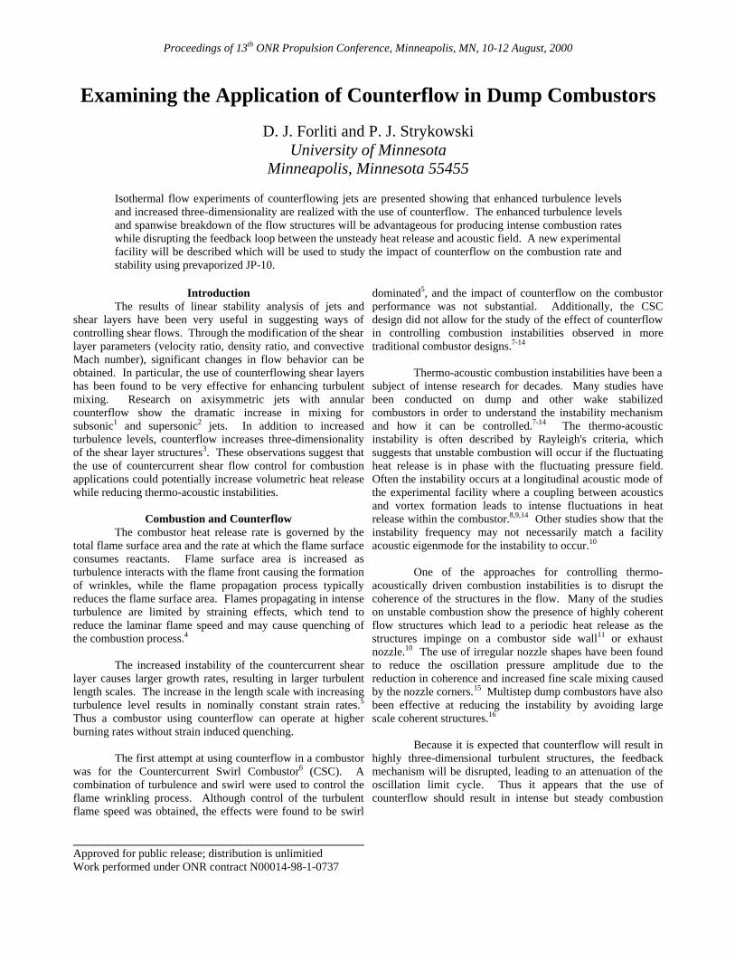
Isothermal ExperimentsThe facility used to study the countercurrent shear
layer is shown in Fig. 1. The two-dimensional facility allows
Figure 1: Countercurrent Shear Flow Facility
for the study of the interaction of two laterally displacedcounterflowing jets. The jet height is 0.5 inches and thespanwise depth of the facility is 4 inches. Particle ImageVelocimetry (PIV) was used to study the flowfield in both theside view (as shown in Fig. 1) and spanwise planes. As shownin Fig. 1, the spanwise measurements were made with thelaser passing through the middle of the primary jet shear layersuch that the effect of counterflow on the spanwise coherencecould be examined. Olive oil droplets generated with aLaskins nozzle were used as seed particles for the PIVmeasurements. The walls of the facility are made fromPlexiglas for optical access.
PIV data was taken for two different cases. As abaseline, an experiment was done for only the primary singlejet. To study the effect of counterflow, the secondary jet wasturned on to a similar jet exit velocity as the primary. For theside view PIV experiments, the primary jet exit velocity wasapproximately 10 m/s. Because of the noisy initial conditionsgenerated from the jets, the spanwise measurements were doneat a reduced velocity (approximately 2 m/s) such that two-dimensional vortices were observed to exist over a largerdomain. This allowed for the study of the effects ofcounterflow on the spanwise coherence.
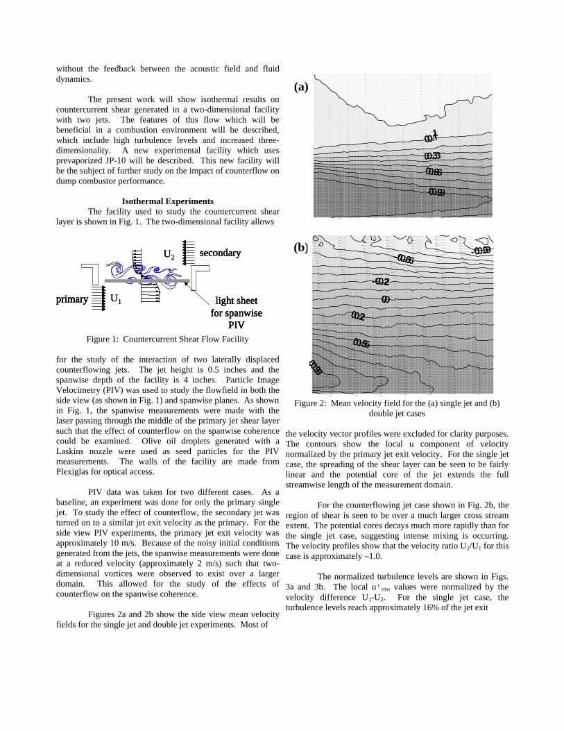
Figures 2a and 2b show the side view mean velocityfields for the single jet and double jet experiments. Most of
Figure 2: Mean velocity field for the (a) single jet and (b)double jet cases
the velocity vector profiles were excluded for clarity purposes.The contours show the local u component of velocitynormalized by the primary jet exit velocity. For the single jetcase, the spreading of the shear layer can be seen to be fairlylinear and the potential core of the jet extends the fullstreamwise length of the measurement domain.
For the counterflowing jet case shown in Fig. 2b, theregion of shear is seen to be over a much larger cross streamextent. The potential cores decays much more rapidly than forthe single jet case, suggesting intense mixing is occurring.The velocity profiles show that the velocity ratio U2/U1 for thiscase is approximately –1.0.
The normalized turbulence levels are shown in Figs.3a and 3b. The local u’rms values were normalized by thevelocity difference U1-U2. For the single jet case, theturbulence levels reach approximately 16% of the jet exit
primary
secondary
light sheetfor spanwise
PIV
primary
secondary
light sheetfor spanwise
PIV
U1
U2
primary
secondary
light sheetfor spanwise
PIV
primary
secondary
light sheetfor spanwise
PIV
U1
U20.9
0.5
0.2
0
-0.2
-0.6-0.9(b)
(a)
0.9
0.6
0.3
0.1
0.9
0.5
0.2
0
-0.2
-0.6-0.9(b)
(a)
0.9
0.6
0.3
0.1

Figure 3: u’/∆U for the (a) single jet and (b) double jet cases
velocity and are confined to the inner portion of the shearlayer, which is in general agreement with the literature. Theturbulence intensity of the counterflowing jet case shows thedramatic effect of applying counterflow. The levels are muchhigher, reaching a maximum of 28% of the difference invelocity. For a fixed velocity difference, the countercurrentshear layer will generate turbulence levels which are 75%higher than the corresponding single stream shear layer. Thehigh turbulence levels are seen to dominate nearly the wholemeasurement domain, which would allow for the flame to beintensely wrinkled over a larger spatial region, resulting invery high turbulent burning velocities.
Because of the flame quenching process induced by turbulentstraining, it is important to evaluate the effects of counterflowon the rms strain rates. Figures 4a and 4b show thenormalized component of strain rate calculated as
H
UU
x
v
y
u
S rms
)(
2
1
2
1
21
2/12
12 −
��
�
�
��
�
�√√↵
����
ƒƒ+
ƒƒ
=
Figure 4: Normalized rms strain rates for the (a) single jet and(b) double jet cases
where H is the jet height. The results show that theapplication of counterflow actually causes a slight reduction inthe peak levels of normalized strain rates. This is veryadvantageous for combustion applications, since the use ofcounterflow generates intense turbulence without high levelsof straining. Counterflow will allow for a combustor tooperate over a wider operating range without detrimentaleffects caused by excessive strain rates.
Instantaneous velocity vector fields of these twocases are shown in Figs. 5a and 5b. Figure 5a shows a typicalsingle jet vector field. As can be seen, the activity in the shearlayer is limited. The scales present are of fairly small size.For the counterflowing case shown in Fig. 5b, the interactionis seen to result in the presence of larger turbulent scales.Large scales of high intensity will result in an increase in theoverall flame surface area.
The spanwise experiments were useful indetermining the effect of counterflow on the spanwisecoherence of the shear layer vortex structures. The laser sheet
0.06
0.06
0.1 6
0.12
0.1 4
0.2 6
0.2 8
0.2 4
0.2 4
0.18
0.16
(a)
(b)
0.06
0.06
0.1 6
0.12
0.1 4
0.2 6
0.2 8
0.2 4
0.2 4
0.18
0.16
(a)
(b)
0.6
11.4 1.2
10.8
0.8
0.6
0.8
0.6
(a)
(b)
0.6
11.4 1.2
10.8
0.8
0.6
0.8
0.6
(a)
(b)

Figure 5: Instantaneous velocity vector fields for the (a)single jet and (b) double jet cases
was placed along the middle of the primary jet shear layer asshown in Fig. 1. Flow visualization was done using a heavilyseeded primary flow with modest seeding in the ambient andsecondary flow for the single and double jet cases,respectively.
Figures 6a and 6b show instantaneous visualizationsof the flow for the single and double jet experiments. Theimage spans approximately 80% of the full facility depth. Theflow conditioning for the primary flow did not render the flowto be highly “clean”, yet it is seen from Fig. 6a that thestructures are nominally two-dimensional. Similar qualitativefeatures are seen at the higher jet speeds, but the streamwiseextent of two dimensionality is reduced, therefore the PIVmeasurements were done at a lower jet velocity.
The visualization shown in Fig. 6b shows thedramatic difference on the spanwise character of the flow withcounterflow. There is no evident spanwise coherence for thiscase, which has approximately the same difference in velocity
Figure 6: Spanwise visualizations for the (a) single jet and (b)double jet cases
as the single jet case. Although the organization of the shearlayer is less coherent, the scales present in the flow are stilllarge.
PIV was conducted on these two cases, andcorrelation coefficients were calculated to quantify the effectof counterflow on the spanwise coherence. For thiscalculation, a reference point in the flow was chosen, and thecorrelation coefficient for the streamwise velocity wascomputed as:
),('),('
),('),('),(1,1 zzxxuzxu
zzxxuzxuzx
refrefrmsrefrefrms
refrefrefref
∆+∆+?∆+∆+?
=∆∆
where u’ is the fluctuation of the u component ofvelocity and ∆x and ∆z are the streamwise and spanwise
(a)
(b)
(a)
(b)
(a)
(b)
(a)
(b)
displacements between the calculation point and the referencepoint.
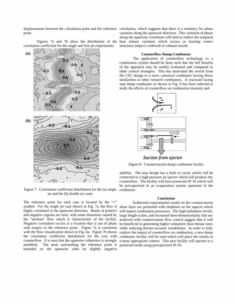
Figures 7a and 7b show the distribution of thecorrelation coefficient for the single and free jet experiments.
Figure 7: Correlation coefficient distribution for the (a) singlejet and the (b) double jet cases
The reference point for each case is located by the “+”symbol. For the single jet case shown in Fig. 7a, the flow ishighly correlated in the spanwise direction. Bands of positiveand negative regions are seen, with some distortion caused bythe “unclean” flow which is characteristic of the facility.Negative correlation occurs at a location that is out of phasewith respect to the reference point. Figure 7a is consistentwith the flow visualization shown in Fig. 6a. Figure 7b showsthe correlation coefficient distribution for the case withcounterflow. It is seen that the spanwise coherence is stronglymodified. The peak surrounding the reference point isbounded on the spanwise sides by slightly negative
correlation, which suggests that there is a tendency for phasevariation along the spanwise direction. This variation of phasealong the spanwise coordinate will tend to reduce the temporalheat release variation which occurs as burning vortexstructures impact a sidewall or exhaust nozzle.
Counterflow Dump CombustorThe application of counterflow technology to a
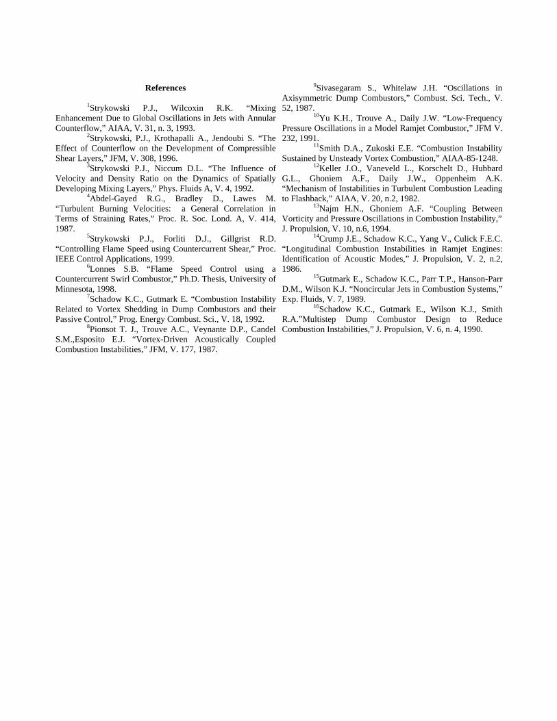
combustion system should be done such that the full benefitsof the approach may be readily evaluated and compared toother control strategies. This has motivated the switch fromthe CSC design to a more canonical combustor having directsimilarities to other research combustors. A rearward facingstep dump combustor as shown in Fig. 8 has been selected tostudy the effects of counterflow on combustion intensity and
Figure 8: Countercurrent dump combustor facility
stability. The step design has a built in cavity which will beconnected to a high pressure air ejector which will produce thecounterflow. The facility will burn premixed JP-10 which willbe prevaporized in an evaporation system upstream of thecombustor.
ConclusionIsothermal experimental results on the countercurrent
shear layer are presented with emphasis on the aspects whichwill impact combustion processes. The high turbulence levels,large length scales, and increased three-dimensionality that areachieved with countercurrent flow control suggest that it willbe beneficial in generating higher volumetric heat release rateswhile reducing thermo-acoustic instabilities. In order to fullyexplore the impact of counterflow on combustion, a new dumpcombustor facility will be used which will place the results ina more appropriate context. This new facility will operate in apremixed mode using prevaporized JP-10.
-0.2 -0.1
0.2
0.3
0.90.6
-0.1-0.2
-0.3
-0.6 0
0.9
0.6
-0.6
-0.3
00.6
0.3
-0.3
-0.3
0.3
(a)
(b)
-0.2 -0.1
0.2
0.3
0.90.6
-0.1-0.2
-0.3
-0.6 0
0.9
0.6
-0.6
-0.3
00.6
0.3
-0.3
-0.3
0.3
(a)
(b)
-0.3
-0.6 0
0.9
0.6
-0.6
-0.3
00.6
0.3
-0.3
-0.3
0.3
(a)
(b)
Suction from ejectorSuction from ejector
References
1Strykowski P.J., Wilcoxin R.K. “MixingEnhancement Due to Global Oscillations in Jets with AnnularCounterflow,” AIAA, V. 31, n. 3, 1993.
2Strykowski, P.J., Krothapalli A., Jendoubi S. “TheEffect of Counterflow on the Development of CompressibleShear Layers,” JFM, V. 308, 1996.
3Strykowski P.J., Niccum D.L. “The Influence ofVelocity and Density Ratio on the Dynamics of SpatiallyDeveloping Mixing Layers,” Phys. Fluids A, V. 4, 1992.
4Abdel-Gayed R.G., Bradley D., Lawes M.“Turbulent Burning Velocities: a General Correlation inTerms of Straining Rates,” Proc. R. Soc. Lond. A, V. 414,1987.
5Strykowski P.J., Forliti D.J., Gillgrist R.D.“Controlling Flame Speed using Countercurrent Shear,” Proc.IEEE Control Applications, 1999.
6Lonnes S.B. “Flame Speed Control using aCountercurrent Swirl Combustor,” Ph.D. Thesis, University ofMinnesota, 1998.
7Schadow K.C., Gutmark E. “Combustion InstabilityRelated to Vortex Shedding in Dump Combustors and theirPassive Control,” Prog. Energy Combust. Sci., V. 18, 1992.
8Pionsot T. J., Trouve A.C., Veynante D.P., CandelS.M.,Esposito E.J. “Vortex-Driven Acoustically CoupledCombustion Instabilities,” JFM, V. 177, 1987.
9Sivasegaram S., Whitelaw J.H. “Oscillations inAxisymmetric Dump Combustors,” Combust. Sci. Tech., V.52, 1987.
10Yu K.H., Trouve A., Daily J.W. “Low-FrequencyPressure Oscillations in a Model Ramjet Combustor,” JFM V.232, 1991.
11Smith D.A., Zukoski E.E. “Combustion InstabilitySustained by Unsteady Vortex Combustion,” AIAA-85-1248.
12Keller J.O., Vaneveld L., Korschelt D., HubbardG.L., Ghoniem A.F., Daily J.W., Oppenheim A.K.“Mechanism of Instabilities in Turbulent Combustion Leadingto Flashback,” AIAA, V. 20, n.2, 1982.
13Najm H.N., Ghoniem A.F. “Coupling BetweenVorticity and Pressure Oscillations in Combustion Instability,”J. Propulsion, V. 10, n.6, 1994.
14Crump J.E., Schadow K.C., Yang V., Culick F.E.C.“Longitudinal Combustion Instabilities in Ramjet Engines:Identification of Acoustic Modes,” J. Propulsion, V. 2, n.2,1986.
15Gutmark E., Schadow K.C., Parr T.P., Hanson-ParrD.M., Wilson K.J. “Noncircular Jets in Combustion Systems,”Exp. Fluids, V. 7, 1989.
16Schadow K.C., Gutmark E., Wilson K.J., SmithR.A.”Multistep Dump Combustor Design to ReduceCombustion Instabilities,” J. Propulsion, V. 6, n. 4, 1990.