
Long Penetration Mode Counterflowing Jets for … · 1 Long Penetration Mode Counterflowing Jets...
18
1 Long Penetration Mode Counterflowing Jets for Supersonic Slender Configurations — A Numerical Study Balaji Shankar Venkatachari * and Gary Cheng † University of Alabama at Birmingham, Birmingham, AL 35294 Chau-Lyan Chang ‡ NASA Langley Research Center, Hampton, VA 23681 Benjamin Zichettello § The Cooper Union for the Advancement of Science and Art, New York, NY 10003 and David L. Bilyeu ** The Ohio State University, Columbus, OH 43210 A novel approach of using counterflowing jets positioned strategically on the aircraft and exploiting its long penetration mode (LPM) of interaction towards sonic-boom mitigation forms the motivation for this study. Given that most previous studies on the counterflowing LPM jet have all been on blunt bodies and at high supersonic or hypersonic flow conditions, exploring the feasibility to obtain a LPM jet issuing from a slender body against low supersonic freestream conditions is the main focus of this study. Computational fluid dynamics computations of axisymmetric models (cone-cylinder and quartic geometry), of relevance to NASA’s High Speed project, are carried out using the space-time conservation element solution element viscous flow solver with unstructured meshes. A systematic parametric study is conducted to determine the optimum combination of counterflowing jet size, mass flow rate, and nozzle geometry for obtaining LPM jets. Details from these computations will be used to assess the potential of the LPM counterflowing supersonic jet as a means of active flow control for enabling supersonic flight over land and to establish the knowledge base for possible future implementation of such technologies. Nomenclature d j = Jet exit diameter d m = Model diameter e = Total energy f = Frequency f = Flux vector F , G = Components of flux vector h = Flux vector in space-time domain L = Length L p = Jet Penetration length M j = Counterflowing jet nozzle Mach number * Postdoctoral Fellow, Dept. of Mechanical Engineering, email: [email protected] , Member AIAA. † Associate Professor, Dept. of Mechanical Engineering, email: [email protected] , AIAA Associate Fellow. ‡ Aerospace Technologist, Computational AeroSciences Branch, email: [email protected] , Senior Member AIAA. § Senior Undergraduate Student, Dept. of Mechanical Engineering, email: [email protected] . ** Ph.D. Candidate, Dept. of Mechanical Engineering, email: [email protected] , Student Member AIAA. https://ntrs.nasa.gov/search.jsp?R=20140000348 2018-07-19T07:54:18+00:00Z
Transcript of Long Penetration Mode Counterflowing Jets for … · 1 Long Penetration Mode Counterflowing Jets...

1
Long Penetration Mode Counterflowing Jets for Supersonic Slender Configurations — A Numerical Study
Balaji Shankar Venkatachari* and Gary Cheng† University of Alabama at Birmingham, Birmingham, AL 35294
Chau-Lyan Chang‡ NASA Langley Research Center, Hampton, VA 23681
Benjamin Zichettello§ The Cooper Union for the Advancement of Science and Art, New York, NY 10003
and
David L. Bilyeu** The Ohio State University, Columbus, OH 43210
A novel approach of using counterflowing jets positioned strategically on the aircraft and exploiting its long penetration mode (LPM) of interaction towards sonic-boom mitigation forms the motivation for this study. Given that most previous studies on the counterflowing LPM jet have all been on blunt bodies and at high supersonic or hypersonic flow conditions, exploring the feasibility to obtain a LPM jet issuing from a slender body against low supersonic freestream conditions is the main focus of this study. Computational fluid dynamics computations of axisymmetric models (cone-cylinder and quartic geometry), of relevance to NASA’s High Speed project, are carried out using the space-time conservation element solution element viscous flow solver with unstructured meshes. A systematic parametric study is conducted to determine the optimum combination of counterflowing jet size, mass flow rate, and nozzle geometry for obtaining LPM jets. Details from these computations will be used to assess the potential of the LPM counterflowing supersonic jet as a means of active flow control for enabling supersonic flight over land and to establish the knowledge base for possible future implementation of such technologies.
Nomenclature d j = Jet exit diameter dm = Model diameter e = Total energy f = Frequency f = Flux vector F, G = Components of flux vector h = Flux vector in space-time domain L = Length Lp = Jet Penetration length M j = Counterflowing jet nozzle Mach number
* Postdoctoral Fellow, Dept. of Mechanical Engineering, email: [email protected], Member AIAA. † Associate Professor, Dept. of Mechanical Engineering, email: [email protected], AIAA Associate Fellow. ‡ Aerospace Technologist, Computational AeroSciences Branch, email: [email protected], Senior Member AIAA. § Senior Undergraduate Student, Dept. of Mechanical Engineering, email: [email protected]. ** Ph.D. Candidate, Dept. of Mechanical Engineering, email: [email protected], Student Member AIAA.
https://ntrs.nasa.gov/search.jsp?R=20140000348 2018-07-19T07:54:18+00:00Z
2
M∞ = Freestream Mach number p = Pressure pamb = Static pressure outside the nozzle exit p j = Static pressure of the jet at the nozzle exit plane p∞ = Freestream static pressure P0 = Total pressure of freestream P0 f = Total pressure at free stagnation point P0 j = Total pressure of counterflowing jet t = Time u, v = Cartesian velocity components U = Conserved flow variable vector V = Space-time region x, y = Cartesian coordinates γ = Ratio of the specific heat ρ = Density
I. Background and Introduction Sonic boom, a result of the shock systems created by supersonic (and hypersonic) vehicle flights coalescing into N-
waves at large distances, has long been a barrier for supersonic flight over land given its environmental impact. This constraint has had severe economic consequences for the aviation industry (both business jets and large commercial supersonic transports), as well as military implications. Although the theory of sonic boom1-3 as well as the methods for its prediction4-6 has been well established, the target of achieving low boom signals still seems elusive. Sonic boom minimization has remained an active area of research since the 1960’s building upon Whitham’s theory1 (the formulation of the “F-function” that correlated the pressure signature in the flowfield about a body of revolution to its geometric shape) that emphasized the need to design supersonic aircrafts as long and slender in shape, and lighter in weight. These research efforts could be classified into two main categories: (i) aircraft configuration studies that focused on deducing optimum shapes that led to smaller over-pressure and impulse; and (ii) use of external force/heat to alter the flowfield around the aircraft to achieve a pressure signature with smaller shock-strength and finite-rise time. Some of the key results that came out of the former include: (a) the study by Jones7 which showed that a delta function was the optimum near-field signature to reduce sonic-boom at large distances; (b) the study by Maclean8 that indicated the possibility of avoiding the formation of N-waves at the ground level by flying the large supersonic aircrafts at moderate altitudes and that the midfield boom signatures (which can be tailored by shaping of the aircraft) persisted at distances far below; and (c) the theory developed by George and Seebass9 for minimizing the front and rear shocks which remains the cornerstone of low-boom configuration studies. The study by Miller and Carlson10 explored the possibility of altering the flowfield around an aircraft, for obtaining a pressure signature with finite rise-time, by utilizing external heat/mass addition to create a long, well-shaped phantom body that envelops the aircraft. The conclusion of their study was that such an idea would necessitate power requirements that is at least twice of that needed to sustain a steady flight, even if one considered the system required to achieve heat/mass addition to be weightless. This conclusion dampened further investigation into the idea of phantom bodies. NASA’s High Speed project and DARPA’s Quiet Supersonic Platform program instituted in recent years has rejuvenated sonic-boom mitigation studies. These programs have led to significant experimental and computational studies that have pushed the art of supersonic vehicle technology further. However, no commercial supersonic aircraft has been developed since the retirement of the Concorde, primarily due to unacceptable sonic-boom levels and low energy efficiency. In this regard, recent efforts on the Quiet SpikeTM by Gulfstream11 and that of the supersonic bi-directional flying wing12 from the University of Miami, holds promise. For more details on the history of the sonic-boom research and the unsolved problems in the area, refer to the excellent review article by Plotkin and Maglieri.13
The current study focuses on the novel approach of using supersonic counterflowing jets positioned strategically on the nose of the aircraft, for sonic-boom mitigation by exploiting the long penetration mode (LPM) of the jet. Previous studies14-17 have demonstrated the ability of LPM counterflowing jets to significantly alter the flowfield around a hypersonic/supersonic blunt-body vehicle and reduce the strength of the bow-shock or disperse it. Although this idea of using an external flowfield seems similar to the effort described by Miller and Carlson,10 the LPM counterflowing jets interact in a more complex manner (to be described in detail later) than a simple heat/mass addition, thereby having the potential to alter the flowfield around an aircraft in a significant manner. Furthermore, the possibility of developing an active flow-control system around this concept makes it even more promising for sonic-boom mitigation. Incorporating such a system into an already shape-optimized, low-boom configuration might be the key to overcome the limitations that has been haunting this field. As mentioned, since most studies on counterflowing jets have been on blunt bodies in

3
hypersonic/high supersonic flow regimes, in this study, we hope to numerically investigate the potential to obtain LPM jets on slender bodies and at low supersonic speeds. The numerical method used in the current study is the space-time conservation element, solution element (CESE) method,18 a time-accurate numerical framework for unstructured meshes designed to enforce strong flux conservation and capture shocks without adhoc numerical tuning. The ability of the CESE method to correctly predict the existence of LPM jets, as well as its behavior, has been demonstrated in our previous studies.16,17 The overall objectives of this initial phase of this research are to (i) investigate the existence of LPM jet interaction for slender bodies of interest22,23 (cone cylinder and quartic geometry) at Mach 1.6 through the use of computational fluid dynamics (CFD); and (ii) conduct parametric study (axisymmetric CFD computations) to determine optimum combination of counterflowing jet size, mass flow rate and nozzle geometry for obtaining LPM interaction. The actual impact on the boom-signature of these slender bodies in the presence of LPM jets and their comparison against available data22,23 will form the second phase of this research.
(a) Short Penetration Mode: Features of the stable flowfield for a central nozzle configuration.
(b) Long Penetration Mode: Features of an unstable flowfield for a central nozzle configuration
Figure 1. Flowfield structure characterization for a jet issuing from a central nozzle against a supersonic freestream.
II. The LPM Concept Prior studies24,25 on counterflowing jets (supersonic) issuing from a central nozzle located on the nose of a blunt-
body into a supersonic freestream, indicate two modes of jet interaction, namely the short penetration mode (SPM) and the LPM. A strong bow shock, a jet terminal shock, a free stagnation point, and a recirculation region characterize the SPM as shown in Fig. 1(a). Here, the jet does not penetrate into the bow-shock and results in a stable flowfield configuration. SPM is observed for jets operating with large jet pressure ratios (large mass flow rates). Operating the jet under pressure conditions slightly larger than the nozzle design conditions results in what is known as the LPM jet. The LPM is an unstable

4
flowfield characterized by the familiar diamond-pattern jet plume that penetrates into the bow-shock, as shown in Fig. 1(b). When the jet, issuing from the nozzle, penetrates the bow shock, the shock standoff distance becomes significantly higher than that found in flows without significant shock penetration (e.g., a SPM jet or a no-jet case) and the shock strength decreases. The ability of the LPM to disperse and weaken the bow shock has been confirmed experimentally15 as well as computationally,17 as can be seen from Fig. 2. LPM jets, however, only exist for a narrow range of conditions beyond which the jet switches into SPM.
The differences in the flow structures between SPM and LPM can be attributed to the difference in the ratio of the static pressure of the jet at the nozzle exit plane and the ambient static pressure outside the nozzle exit ( p j / pamb ). A jet with p j / pamb > 1 is characterized as an under-expanded jet, while for p j / pamb >> 1 , the jet is said to be highly under-
expanded. In a slightly under-expanded jet, as the flow expands into the ambient gas with low-pressures, expansion fans are created at the nozzle exit. The free jet boundary reflects these expansion fans as compression waves, which then coalesce to form an incident shock. The incident shock (see Fig. 1(b)) then undergoes a regular reflection (without forming a Mach disk) at the jet axis. The resulting diverging shock, once again, interacts with the jet boundary creating another incident shock and the process repeats resulting in the familiar diamond shock-cell structure. The consecutive deceleration by the shock cell slows down the jet plume until it stagnates at the free stagnation point. At this point, the jet plume meets the post-normal shock flow near the centerline, with both their total pressures reaching a value of bow shock flow at P0 f . A normal shock occurring in the decelerating region of a flow is understood to be unstable. The LPM jets belong to this class; the under-expanded jet adjusts itself to get the terminating normal shock to end up in the accelerating flow region. In the case of the highly under-expanded jet, the incident shock forms a Mach disk, instead of undergoing a regular reflection at the jet. The Mach disk allows for a quick deceleration of the supersonic jet, helping it to come into equilibrium with the ambient flowfield. Moreover, since this normal shock remains within the accelerating region of the jet, the flow remains very stable.
Experiment15 (Schlieren)
CFD17 (Density gradient)
SPM LPM
Figure 2. Contrasting SPM against LPM jets.
Given this ability of the LPM jet to weaken the bow-shock, it generated an interest to investigate its ability in sonic-boom mitigation. To explore that potential, time-averaged pressure signatures were extracted from numerical studies17 at a certain distance away from the blunt-body surface (see Fig. 3(a)), for the cases of (i) without jet, (ii) with LPM jet, and (iii) with SPM jet. As can be seen from Fig. 3(b), the normalized pressure disturbance signatures for the no jet and SPM jet

5
cases indicate a sharp discontinuity, similar to the pressure signatures obtained from supersonic aircraft. Such a pressure signature is usually responsible for leading portion of the N-wave causing sonic boom. In contrast, the LPM’s pressure signature is devoid of any sharp discontinuities and consists of a series of ramps in pressure. The LPM jet’s notional ground signature (provided by Kenneth Plotkins of Wyle Laboratories, VA) was obtained using PCBoom27 to propagate the pressure signature 35,000 ft under the assumption of a Mach 1.4 flow, after adopting the following steps: (i) the LPM jet’s pressure signature was appropriately scaled in amplitude to the appropriate pressure levels of that of a low boom aircraft and was also scaled in length; (ii) closure ramp was added to the end of the pressure signature to account for the expansion region and bringing the pressure levels to that of freestream conditions. Fig. 4 shows the notional ground boom signature for the LPM jet, with and without rounding by atmospheric absorption. This signature is similar to some of the favorable pressure signatures sought after by the sonic-boom mitigation community.
(a) Indication of the off-body location at which the pressure disturbance signature is obtained.
(b) Normalized pressure-disturbance signature at the indicated location for the conditions of no-jet, SPM and LPM jets.
Figure 3. Pressure disturbance signature and its extraction details for the case of a blunt-body with counterflowing jets.
(a) Ground boom signature without smoothing from atmospheric absorption.
(b) Ground boom signature with smoothing from atmospheric absorption.
Figure 4. Notional ground boom-signature of the LPM jet.
6
III. Space-Time CESE Method
To capture the physics faithfully and efficiently, the high-resolution, genuinely-multidimensional space-time CESE18 framework solves the original integral form of the conservation laws rather than the differential form. The method is built around the concept of treating space and time synergistically and conserving fluxes in both space and time. The space-time CESE framework is unique for several reasons: (i) space and time are unified and treated as a single entity; (ii) local and global space-time flux conservation is enforced; (iii) no dimensional-splitting approach is used, resulting in a truly multidimensional scheme; (iv) both the conservative flow variables and its spatial derivatives are treated as dependent variables; (v) a space-time staggered stencil is used such that fluxes at the cell interfaces can be evaluated without solving the Riemann problem; (vi) schemes are built from non-dissipative (space-time inversion invariant) core schemes which allows for efficient control of numerical dissipation; and (vii) it is naturally compatible with unstructured triangular and tetrahedral meshes. To date, the CESE based solvers have been utilized to solve a variety of problems including inviscid acoustic waves, traveling and interacting shocks, detonation waves, and cavitation flows.19 – 21
To bring out the clear conceptual difference between conventional CFD algorithms (finite-difference and finite-volume methods) and the CESE framework, consider the differential form of a conservation law in multiple spatial dimensions that is given by
∂U∂t
+∇⋅ f (U) = 0 (1)
where U is the conserved variable, f (U) is its spatial flux vector, and the symbol ∇⋅ denotes the divergence operator in the spatial domain. Finite-difference schemes model only the differential form of Eq. (1). Note that a set of physical conservation laws, in their original form, is a collection of flux conservation equations in space-time. These conservation laws are represented by a set of integral equations. The differential form of these laws is obtained from the integral form using an extra assumption that the physical solution is smooth. Consequently, by modeling only the differential form, finite-difference schemes, in general, lack the capacity to capture solution discontinuities and to ensure flux conservation. In an attempt to capture physics more accurately, conventional finite-volume schemes model the flux-balance form of Eq. (1) over a fixed spatial domain, i.e.,
d
dtU dV
V∫ = − f (U)• ds
S(V )∫ (2)
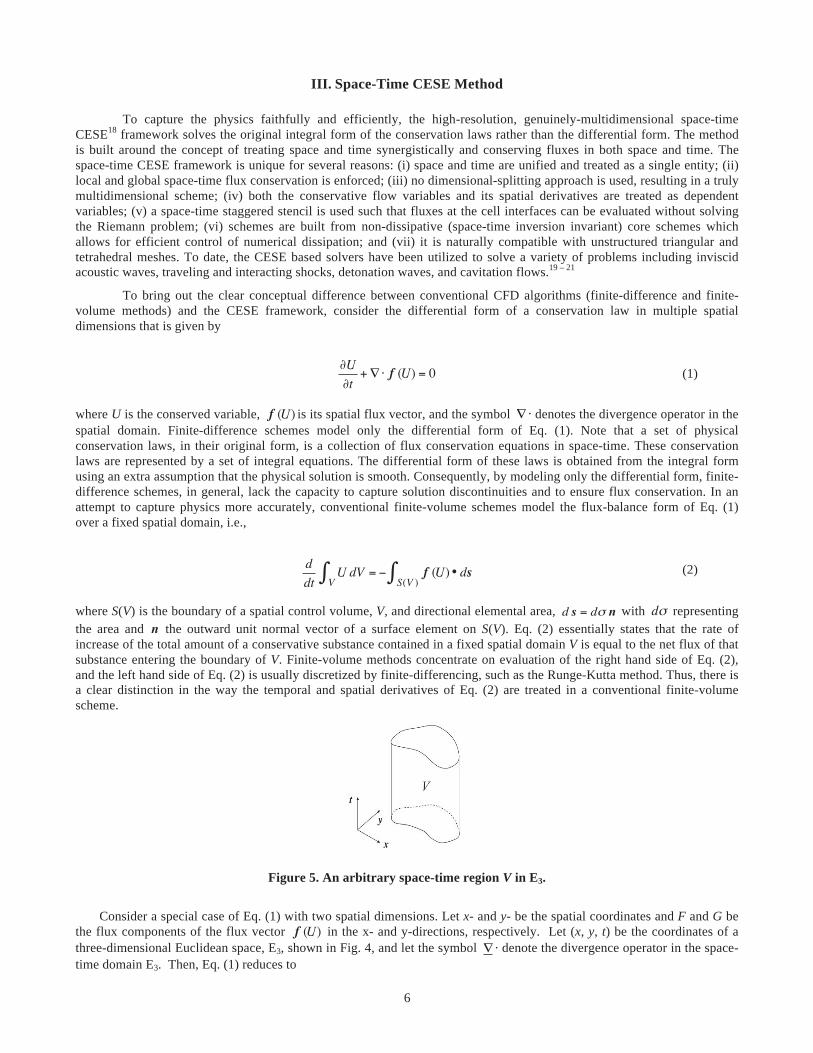
where S(V) is the boundary of a spatial control volume, V, and directional elemental area, d s = dσ n with dσ representing the area and n the outward unit normal vector of a surface element on S(V). Eq. (2) essentially states that the rate of increase of the total amount of a conservative substance contained in a fixed spatial domain V is equal to the net flux of that substance entering the boundary of V. Finite-volume methods concentrate on evaluation of the right hand side of Eq. (2), and the left hand side of Eq. (2) is usually discretized by finite-differencing, such as the Runge-Kutta method. Thus, there is a clear distinction in the way the temporal and spatial derivatives of Eq. (2) are treated in a conventional finite-volume scheme.
Figure 5. An arbitrary space-time region V in E3.
Consider a special case of Eq. (1) with two spatial dimensions. Let x- and y- be the spatial coordinates and F and G be
the flux components of the flux vector f (U) in the x- and y-directions, respectively. Let (x, y, t) be the coordinates of a three-dimensional Euclidean space, E3, shown in Fig. 4, and let the symbol ∇⋅ denote the divergence operator in the space-time domain E3. Then, Eq. (1) reduces to
7
∇ ⋅h ≡
∂U∂ t
+∂F∂x
+∂G∂y
= 0 (3)
where h = (F,G,U) is the space-time flux vector. If the Navier-Stokes equations are solved as the governing equations with perfect gas flow assumption, then U is defined as U = (ρ, ρu, ρv, e), where the flow variables ρ, u, v, and e represent density, two velocity components, and total energy (defined as e = p /(γ −1) + ρ(u2 + v2) /2 , where p denotes the pressure), respectively. The flux vectors F and G include both the inviscid (Euler) and the viscous parts. Invoking Gauss’s divergence theorem in E3, Eq. (3) can be expressed in the following integral form:
h ⋅ds S(V )∫ = 0 (4)
S(V) is the boundary of an arbitrary space-time region V (see Fig. 2) in E3. Because h ⋅d s is the space-time flux of h leaving the space-time region V through the surface element ds , Eq. (4) simply states that the total space-time flux of h leaving V through its boundary vanishes, i.e., the rigorous statement of the space-time flux conservation law associated with Eq. (3). Unlike Eq. (2), the form presented in Eq. (4) treats both the temporal and spatial terms of Eq. (1) in a unified manner. This is a crucial difference that, at the conceptual level, separates CESE schemes from the conventional finite-volume schemes. More details on CESE schemes can be obtained from Refs. 18 and 26.
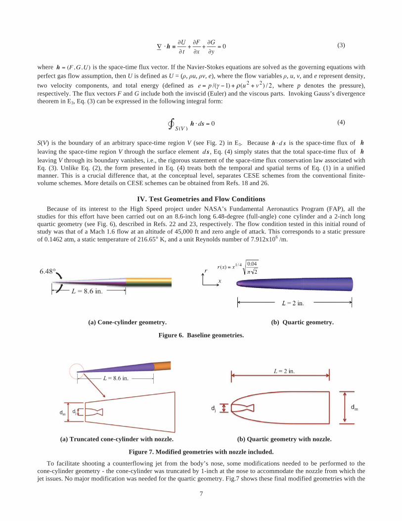
IV. Test Geometries and Flow Conditions Because of its interest to the High Speed project under NASA’s Fundamental Aeronautics Program (FAP), all the studies for this effort have been carried out on an 8.6-inch long 6.48-degree (full-angle) cone cylinder and a 2-inch long quartic geometry (see Fig. 6), described in Refs. 22 and 23, respectively. The flow condition tested in this initial round of study was that of a Mach 1.6 flow at an altitude of 45,000 ft and zero angle of attack. This corresponds to a static pressure of 0.1462 atm, a static temperature of 216.65° K, and a unit Reynolds number of 7.912x10⁶ /m.
(a) Cone-cylinder geometry. (b) Quartic geometry.
Figure 6. Baseline geometries.
(a) Truncated cone-cylinder with nozzle. (b) Quartic geometry with nozzle.
Figure 7. Modified geometries with nozzle included.
To facilitate shooting a counterflowing jet from the body’s nose, some modifications needed to be performed to the cone-cylinder geometry - the cone-cylinder was truncated by 1-inch at the nose to accommodate the nozzle from which the jet issues. No major modification was needed for the quartic geometry. Fig.7 shows these final modified geometries with the
8
nozzle in place. Contoured nozzle designed for an earlier study15 with jet exit number of Mach 2.94 was predominantly used in this study, by scaling it appropriately to facilitate its placement into the geometry of interest. The exact sizing of the nozzles utilized will be given in the subsequent section. The nozzle inlet was assumed to be connected to a reservoir chamber at stagnation conditions of 300° K and that its pressure was varied according to the desired jet pressure and its corresponding mass flow rate.
V. Computational Details Given that the focus of these studies lies in gaining a better understanding about the existence of LPM jets in slender
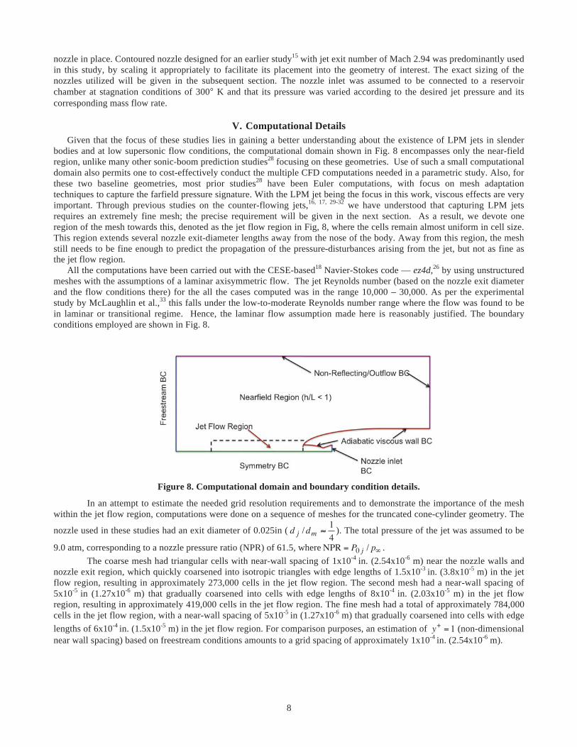
bodies and at low supersonic flow conditions, the computational domain shown in Fig. 8 encompasses only the near-field region, unlike many other sonic-boom prediction studies28 focusing on these geometries. Use of such a small computational domain also permits one to cost-effectively conduct the multiple CFD computations needed in a parametric study. Also, for these two baseline geometries, most prior studies28 have been Euler computations, with focus on mesh adaptation techniques to capture the farfield pressure signature. With the LPM jet being the focus in this work, viscous effects are very important. Through previous studies on the counter-flowing jets,16, 17, 29-32 we have understood that capturing LPM jets requires an extremely fine mesh; the precise requirement will be given in the next section. As a result, we devote one region of the mesh towards this, denoted as the jet flow region in Fig, 8, where the cells remain almost uniform in cell size. This region extends several nozzle exit-diameter lengths away from the nose of the body. Away from this region, the mesh still needs to be fine enough to predict the propagation of the pressure-disturbances arising from the jet, but not as fine as the jet flow region.
All the computations have been carried out with the CESE-based18 Navier-Stokes code — ez4d,26 by using unstructured meshes with the assumptions of a laminar axisymmetric flow. The jet Reynolds number (based on the nozzle exit diameter and the flow conditions there) for the all the cases computed was in the range 10,000 – 30,000. As per the experimental study by McLaughlin et al.,33 this falls under the low-to-moderate Reynolds number range where the flow was found to be in laminar or transitional regime. Hence, the laminar flow assumption made here is reasonably justified. The boundary conditions employed are shown in Fig. 8.
Figure 8. Computational domain and boundary condition details.
In an attempt to estimate the needed grid resolution requirements and to demonstrate the importance of the mesh within the jet flow region, computations were done on a sequence of meshes for the truncated cone-cylinder geometry. The
nozzle used in these studies had an exit diameter of 0.025in ( d j /dm ≈1
4). The total pressure of the jet was assumed to be
9.0 atm, corresponding to a nozzle pressure ratio (NPR) of 61.5, whereNPR = P0 j / p∞ . The coarse mesh had triangular cells with near-wall spacing of 1x10⁻⁴ in. (2.54x10⁻⁶ m) near the nozzle walls and
nozzle exit region, which quickly coarsened into isotropic triangles with edge lengths of 1.5x10⁻³ in. (3.8x10⁻⁵ m) in the jet flow region, resulting in approximately 273,000 cells in the jet flow region. The second mesh had a near-wall spacing of 5x10⁻⁵ in (1.27x10⁻⁶ m) that gradually coarsened into cells with edge lengths of 8x10⁻⁴ in. (2.03x10⁻⁵ m) in the jet flow region, resulting in approximately 419,000 cells in the jet flow region. The fine mesh had a total of approximately 784,000 cells in the jet flow region, with a near-wall spacing of 5x10⁻⁵ in (1.27x10⁻⁶ m) that gradually coarsened into cells with edge lengths of 6x10⁻⁴ in. (1.5x10⁻⁵ m) in the jet flow region. For comparison purposes, an estimation of y+ = 1 (non-dimensional near wall spacing) based on freestream conditions amounts to a grid spacing of approximately 1x10⁻⁴ in. (2.54x10⁻⁶ m).

9
(a) Coarse mesh results (~273,000 cells).
(b) Medium mesh results (~419,000 cells).
(c) Fine mesh results (~784,000 cells).
Figure 9. Influence of mesh on jet development. Instantaneous Mach contours are shown on the left and the close-up view of the mesh near the nozzle exit is shown on the right.
As can be seen from Fig. 9, when the mesh quickly coarsens in the jet flow region, the jet appears to wrongly settle into the SPM, indicating a mixing enhancement due to numerical dissipation. This happens despite the near-wall spacing being y+ = 1. Although not shown here, a mesh with near-wall mesh spacing y+ = 5 was also tested and that also indicated a jet settling in to SPM. As indicated by the medium and fine mesh results, one is able to capture the LPM jet with a smaller disparity across cell sizes in the critical region. This indicates the need for a uniform cell-size distribution within the jet flow region, so that one can capture the highly unsteady jet-shear layer found in LPM jets. The time-averaged jet penetration lengths from the computations done using the medium and fine mesh are almost equal (although the results shown here are at slightly different time instances, causing a small difference in the penetration lengths), indicating grid convergence of the
10
solution. Given that a wide range of pressure conditions need to be tested in the parametric study, the fine mesh was utilized throughout. A mesh with similar grid resolution was used in the study of quartic geometry also.
VI. Parametric Studies In an attempt to understand the ability to achieve LPM jets issuing from slender bodies at low supersonic speeds, some key parameters, indicated by earlier studies on counterflowing jets,25, 34-36 were explored. Results from those studies form the crux of this section.
A. Influence of Nozzle Exit-to-body Diameter Ratio Given that the primary motivation is to make the LPM jet push the leading shock as far away from the body as
possible, thereby weakening it and creating a more favorable pressure signature that would mitigate the sonic boom, it is expected that the mass flow rate of the jet would play a key role. To determine the optimum nozzle size, nozzle of two different exit diameters, obtained by scaling the baseline nozzle geometry, were tested for the truncated cone-cylinder and quartic geometries.
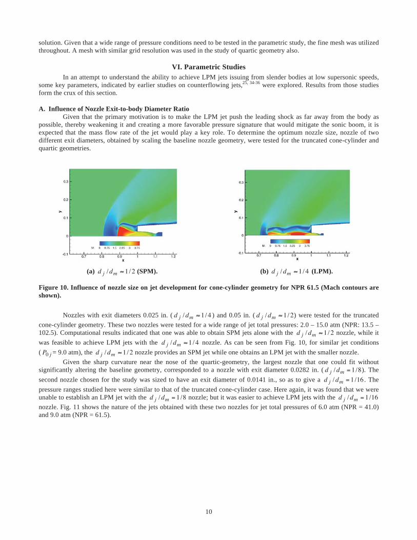
(a) d j /dm ≈ 1/2 (SPM). (b) d j /dm ≈ 1/4 (LPM).
Figure 10. Influence of nozzle size on jet development for cone-cylinder geometry for NPR 61.5 (Mach contours are shown).
Nozzles with exit diameters 0.025 in. ( d j /dm ≈ 1/4 ) and 0.05 in. ( d j /dm ≈ 1/2) were tested for the truncated
cone-cylinder geometry. These two nozzles were tested for a wide range of jet total pressures: 2.0 – 15.0 atm (NPR: 13.5 – 102.5). Computational results indicated that one was able to obtain SPM jets alone with the d j /dm ≈ 1/2 nozzle, while it was feasible to achieve LPM jets with the d j /dm ≈ 1/4 nozzle. As can be seen from Fig. 10, for similar jet conditions ( P0 j = 9.0 atm), the d j /dm ≈ 1/2 nozzle provides an SPM jet while one obtains an LPM jet with the smaller nozzle.
Given the sharp curvature near the nose of the quartic-geometry, the largest nozzle that one could fit without significantly altering the baseline geometry, corresponded to a nozzle with exit diameter 0.0282 in. ( d j /dm = 1/8). The second nozzle chosen for the study was sized to have an exit diameter of 0.0141 in., so as to give a d j /dm = 1/16 . The pressure ranges studied here were similar to that of the truncated cone-cylinder case. Here again, it was found that we were unable to establish an LPM jet with the d j /dm = 1/8 nozzle; but it was easier to achieve LPM jets with the d j /dm = 1/16 nozzle. Fig. 11 shows the nature of the jets obtained with these two nozzles for jet total pressures of 6.0 atm (NPR = 41.0) and 9.0 atm (NPR = 61.5).

11
d j /dm = 1/8
d j /dm = 1/16
P0 j = 6.0 atm P0 j = 9.0 atm
Figure 11. Influence of nozzle size on jet development for quartic geometry.
Based on the results for the two geometries, the smaller the d j /dm ratio, the easier it is to establish LPM jets. A
careful investigation of the computed streamline patterns shown in Fig.12, indicates that the ability to establish a dynamic recirculation region of considerable size above the nozzle exit region, is vital for the development of LPM jets. The shear layer that encompasses this recirculation region can be divided into a part that flows over the top of the body and a part that flows down the frontal area (the region above the nozzle exit). A smaller d j /dm ratio allows relatively more flow in the frontal area, thereby carrying more momentum downstream of the jet. A consequence of this is that the reattachment point becomes dynamic, thereby weakly altering the pressure in the region above the nozzle exit, leading to unsteady LPM jet behavior.
To understand this behavior pattern, a few probes were placed in the region above nozzle exit region, the recirculating flow region and near the jet shear layer (see Fig.13). Shown in Fig. 13 is the spectrum of the data collected at some of these probes for the quartic geometry. The data for the d j /dm = 1/8 nozzle was for a jet with P0 j = 6.0 atm, while that for the d j /dm = 1/16 nozzle was for a jet with P0 j = 10.0 atm, corresponding to a condition at which the peak jet penetration distance was obtained. Approximately 100,000 data points were used in computing the spectrum for each of these cases.
12
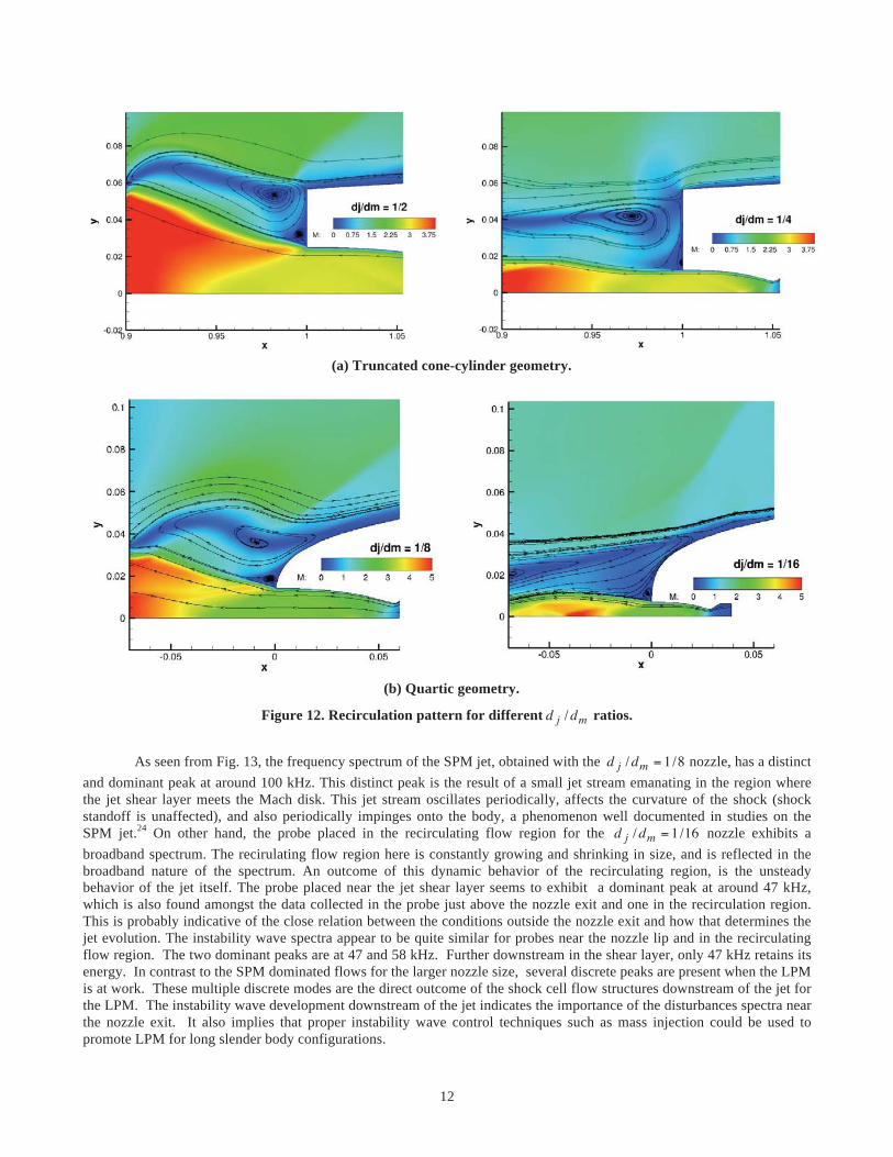
(a) Truncated cone-cylinder geometry.
(b) Quartic geometry.
Figure 12. Recirculation pattern for different d j /dm ratios.
As seen from Fig. 13, the frequency spectrum of the SPM jet, obtained with the d j /dm = 1/8 nozzle, has a distinct
and dominant peak at around 100 kHz. This distinct peak is the result of a small jet stream emanating in the region where the jet shear layer meets the Mach disk. This jet stream oscillates periodically, affects the curvature of the shock (shock standoff is unaffected), and also periodically impinges onto the body, a phenomenon well documented in studies on the SPM jet.24 On other hand, the probe placed in the recirculating flow region for the d j /dm = 1/16 nozzle exhibits a broadband spectrum. The recirulating flow region here is constantly growing and shrinking in size, and is reflected in the broadband nature of the spectrum. An outcome of this dynamic behavior of the recirculating region, is the unsteady behavior of the jet itself. The probe placed near the jet shear layer seems to exhibit a dominant peak at around 47 kHz, which is also found amongst the data collected in the probe just above the nozzle exit and one in the recirculation region. This is probably indicative of the close relation between the conditions outside the nozzle exit and how that determines the jet evolution. The instability wave spectra appear to be quite similar for probes near the nozzle lip and in the recirculating flow region. The two dominant peaks are at 47 and 58 kHz. Further downstream in the shear layer, only 47 kHz retains its energy. In contrast to the SPM dominated flows for the larger nozzle size, several discrete peaks are present when the LPM is at work. These multiple discrete modes are the direct outcome of the shock cell flow structures downstream of the jet for the LPM. The instability wave development downstream of the jet indicates the importance of the disturbances spectra near the nozzle exit. It also implies that proper instability wave control techniques such as mass injection could be used to promote LPM for long slender body configurations.

13
Probe locations
Probe near nozzle lip
Probe in the recirculating flow region
Probe near jet shear
layer
d j /dm = 1/8 d j /dm = 1/16
Figure 13. Probe data analysis comparison for two d j /dm ratios (quartic geometry).
14
A. Influence of Jet Total Pressures The existence of a range of pressures at which the LPM jet regime can be established offers some flexibility in
case the free-=stream condition changes continuously. This aspect could become important, especially during vehicle acceleration/deceleration at supersonic speeds. As a result, this part of the study dealt with establishing pressure ranges at which LPM jets can be found for each of these slender bodies.
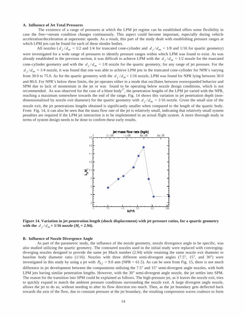
All nozzles ( d j /dm = 1/2 and 1/4 for truncated cone-cylinder and d j /dm = 1/8 and 1/16 for quartic geometry) were investigated for a wide range of pressures to identify pressure ranges within which LPM was found to exist. As was already established in the previous section, it was difficult to achieve LPM with the d j /dm = 1/2 nozzle for the truncated cone-cylinder geometry and with the d j /dm = 1/8 nozzle for the quartic geometry, for any range of jet pressure. For the d j /dm = 1/4 nozzle, it was found that one was able to achieve LPM jets in the truncated cone-cylinder for NPR’s varying from 30.0 to 75.0. As for the quartic geometry with the d j /dm = 1/16 nozzle, LPM was found for NPR lying between 30.0 and 80.0. For NPR’s below these limits, the jet operates either in a mode that oscillates between overexpanded behavior and SPM due to lack of momentum in the jet or was found to be operating below nozzle design conditions, which is not recommended. As was observed for the case of a blunt body17, the penetration lengths of the LPM jet varied with the NPR, reaching a maximum somewhere towards the end of the range. Fig. 14 shows this variation in jet penetration depth (non-dimensionalized by nozzle exit diameter) for the quartic geometry with d j /dm = 1/16 nozzle. Given the small size of the nozzle exit, the jet penetrations lengths obtained is significantly smaller when compared to the length of the quartic body. From Fig. 14, it can also be seen that the mass flow rate of the jet is relatively small, indicating that relatively small system penalties are required if the LPM jet interaction is to be implemented in an actual flight system. A more thorough study in terms of system design needs to be done to confirm these early results.
Figure 14. Variation in jet penetration length (shock displacement) with jet pressure ratios, for a quartic geometry with the d j /dm = 1/16 nozzle (Mj = 2.94).
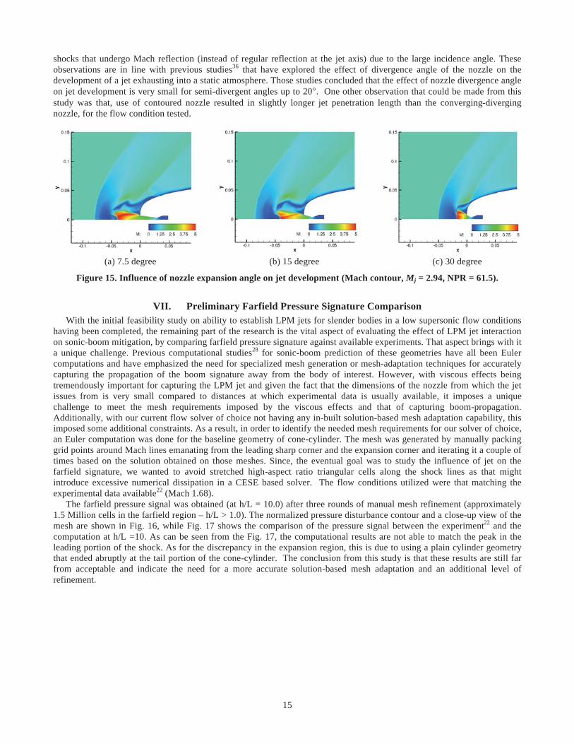
B. Influence of Nozzle Divergence Angle As part of the parametric study, the influence of the nozzle geometry, nozzle divergence angle to be specific, was
also studied utilizing the quartic geometry. The contoured nozzles used in the initial study were replaced with converging-diverging nozzles designed to provide the same jet Mach number (2.94) while retaining the same nozzle exit diameter to baseline body diameter ratio (1/16). Nozzles with three different semi-divergent angles (7.5°, 15°, and 30°) were investigated in this study by using a jet with P0 j = 9.0 atm (NPR = 61.5). As can be seen from Fig. 15, there is not much difference in jet development between the computations utilizing the 7.5° and 15° semi-divergent angle nozzles, with both LPM jets having similar penetration lengths. However, with the 30° semi-divergent angle nozzle, the jet settles into SPM. The reason for the transition into SPM could be explained as follows. The high-pressure jet, as it leaves the nozzle exit, tries to quickly expand to match the ambient pressure conditions surrounding the nozzle exit. A large divergent angle nozzle, allows the jet to do so, without needing to alter its flow direction too much. Then, as the jet boundary gets deflected back towards the axis of the flow, due to constant pressure at the jet boundary, the resulting compression waves coalesce to form
15
shocks that undergo Mach reflection (instead of regular reflection at the jet axis) due to the large incidence angle. These observations are in line with previous studies36 that have explored the effect of divergence angle of the nozzle on the development of a jet exhausting into a static atmosphere. Those studies concluded that the effect of nozzle divergence angle on jet development is very small for semi-divergent angles up to 20°. One other observation that could be made from this study was that, use of contoured nozzle resulted in slightly longer jet penetration length than the converging-diverging nozzle, for the flow condition tested.
(a) 7.5 degree (b) 15 degree (c) 30 degree
Figure 15. Influence of nozzle expansion angle on jet development (Mach contour, Mj = 2.94, NPR = 61.5).
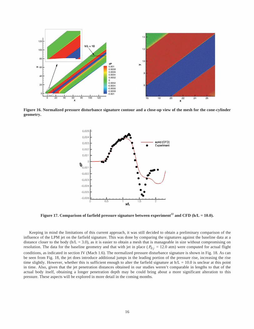
VII. Preliminary Farfield Pressure Signature Comparison With the initial feasibility study on ability to establish LPM jets for slender bodies in a low supersonic flow conditions having been completed, the remaining part of the research is the vital aspect of evaluating the effect of LPM jet interaction on sonic-boom mitigation, by comparing farfield pressure signature against available experiments. That aspect brings with it a unique challenge. Previous computational studies28 for sonic-boom prediction of these geometries have all been Euler computations and have emphasized the need for specialized mesh generation or mesh-adaptation techniques for accurately capturing the propagation of the boom signature away from the body of interest. However, with viscous effects being tremendously important for capturing the LPM jet and given the fact that the dimensions of the nozzle from which the jet issues from is very small compared to distances at which experimental data is usually available, it imposes a unique challenge to meet the mesh requirements imposed by the viscous effects and that of capturing boom-propagation. Additionally, with our current flow solver of choice not having any in-built solution-based mesh adaptation capability, this imposed some additional constraints. As a result, in order to identify the needed mesh requirements for our solver of choice, an Euler computation was done for the baseline geometry of cone-cylinder. The mesh was generated by manually packing grid points around Mach lines emanating from the leading sharp corner and the expansion corner and iterating it a couple of times based on the solution obtained on those meshes. Since, the eventual goal was to study the influence of jet on the farfield signature, we wanted to avoid stretched high-aspect ratio triangular cells along the shock lines as that might introduce excessive numerical dissipation in a CESE based solver. The flow conditions utilized were that matching the experimental data available22 (Mach 1.68). The farfield pressure signal was obtained (at h/L = 10.0) after three rounds of manual mesh refinement (approximately 1.5 Million cells in the farfield region – h/L > 1.0). The normalized pressure disturbance contour and a close-up view of the mesh are shown in Fig. 16, while Fig. 17 shows the comparison of the pressure signal between the experiment22 and the computation at h/L =10. As can be seen from the Fig. 17, the computational results are not able to match the peak in the leading portion of the shock. As for the discrepancy in the expansion region, this is due to using a plain cylinder geometry that ended abruptly at the tail portion of the cone-cylinder. The conclusion from this study is that these results are still far from acceptable and indicate the need for a more accurate solution-based mesh adaptation and an additional level of refinement.
16
Figure 16. Normalized pressure disturbance signature contour and a close-up view of the mesh for the cone-cylinder geometry.
Figure 17. Comparison of farfield pressure signature between experiment22 and CFD (h/L = 10.0).
Keeping in mind the limitations of this current approach, it was still decided to obtain a preliminary comparison of the influence of the LPM jet on the farfield signature. This was done by comparing the signatures against the baseline data at a distance closer to the body (h/L = 3.0), as it is easier to obtain a mesh that is manageable in size without compromising on resolution. The data for the baseline geometry and that with jet in place (P0 j = 12.0 atm) were computed for actual flight conditions, as indicated in section IV (Mach 1.6). The normalized pressure disturbance signature is shown in Fig. 18. As can be seen from Fig. 18, the jet does introduce additional jumps in the leading portion of the pressure rise, increasing the rise time slightly. However, whether this is sufficient enough to alter the farfield signature at h/L = 10.0 is unclear at this point in time. Also, given that the jet penetration distances obtained in our studies weren’t comparable in lengths to that of the actual body itself, obtaining a longer penetration depth may be could bring about a more significant alteration to this pressure. These aspects will be explored in more detail in the coming months.

17
Figure 18. Comparison of pressure disturbance signatures at h/L = 3.0 with and without jet.
VIII. Conclusions The feasibility of achieving counterflowing LPM jets issuing from slender bodies against low supersonic flow conditions, as a means towards sonic-boom mitigation, was numerically investigated in this study. Two slender-body geometries of interest to the High Speed project under NASA’s FAP, namely a 6.48-degree cone-cylinder and a quartic geometry were the subject of investigation here. A parametric study on system parameters needed to achieve an LPM jet issuing from these slender bodies, was carried out using axisymmetric CFD computations. The parameters explored in the study include (i) the sizing of the jet, (ii) optimal jet mass flow rate /pressure conditions, and (iii) nozzle geometry. From the parametric study, the ratio of the diameter at nozzle exit to the diameter of the body was identified to be one of the key factors. The smaller this ratio is, the easier it is to establish an LPM jet. A pressure range that will sustain an LPM jet was identified for each of the chosen geometries; and based on that, the jet mass flow rates corresponding to these pressures were found to be relatively small. This information on smaller mass flow rate requirements augurs well in case this technology has the potential for an implementation in a real flight system. Nozzle exit angle, with the exception of large exit angles (>30°), was found to not have much of an impact on the jet development. Given the challenges in capturing the farfield pressure signature in the presence of the LPM jet and without any in-built mesh adaptation capability, plenty of work remains towards evaluation of the actual impact of the LPM jet interaction on sonic-boom mitigation. Towards this end, we may have to rely on using a signature propagation tool that will utilize the flow solution from the body near-field region (less than one body length). These efforts will be reported in a later work.
Acknowledgments Balaji Shankar Venkatachari and Gary Cheng acknowledge financial support by the National Institute of Airspace (NIA) through cooperative agreement 2922. Chau-Lyan Chang acknowledges support from the High Speed project under NASA’s Fundamental Aeronautics Program (FAP). Benjamin Zichettello and David Bilyeu acknowledge support from the Langley Aerospace Research Student Scholars (LARSS) program. The authors would like to thank Endwell Daso and Rebecca Farr of NASA Marshall Research Center, Kenneth Plotkins of Wyle Laboratories, and Bil Kleb of NASA Langley Research Center for all their valuable technical inputs and guidance during the course of the project. The authors would also like to thank Peter Coen and Joseph Morrison of NASA Langley Research Center for their support and feedback.
References 1 Whitham, G. B., “The Flow Pattern of a Supersonic Projectile,” Communications on Pure and Applied Mathematics, Vol. 5, No. 3,
1952, pp. 301–348. 2 Walkden, F., “The Shock Pattern of a Wing-body Combination, Far from the Flight Path,” Aeronautical Quarterly, Vol. IX, Pt. 2,
1958, pp. 164–194. 3 George, A. R., “Reduction of Sonic Boom by Azimuthal Redistribution of Overpressure.” AIAA Journal, Vol. 7, 1969, pp. 291–298. 4 Hayes, W. D., Haefeli, R. C., and Kulsrud, H. E., “Sonic Boom Propagation in a Stratified Atmosphere, With Computer Program,”
NASA CR-1299, 1969. 5 Crow, S. C., “Distortion of Sonic Bangs by Atmospheric Turbulence,” Journal of Fluid Mechanics, Vol. 37, 1969, pp. 529-56. 6 Plotkin, K. J., and George, A. R., “Propagation of Weak Shock Waves Through Turbulence,” Journal of Fluid Mechanics, Vol. 54,
1972, pp. 449-467. 7 Jones, L. B., “Lower Bounds for Sonic Bang in the Far-Field,” Aeronautics Quarterly, Vol. XVIII, Pt. 1, 1967, pp. 1-21. 8 McLean, F. E., “Some Non-asymptotic Effects on the Sonic Boom of Large Airplanes,” NASA TN D- 2877, 1965.

18
9 George, A. R., and Seebass, R., “Sonic Boom Minimization Including Both Front and Real Shocks,” AIAA Journal, Vol. 9, 1971, pp. 2091-2093.
10 Miller, D. S., and Carlson, H. W., “ A Study of the Application of Heat Or Force Fields to the Sonic-boom-minimization Problem,” NASA TN D-5582, 1969.
11 Howe, D., Simmons, F., and Freund, D., “Development of the Gulfstream Quiet SpikeTM for Sonic Boom Minimization,” AIAA Paper 2008-124, 2008.
12 Berger, C., Carmona, K., Espinal, D., Im, H. S., and Zha, G. C., “Supersonic Bi-Directional Flying Wing Configuration with Low Sonic Boom and High Aerodynamic Efficiency,” AIAA Paper 2011-3663, 2011.
13 Plotkin, K. J., and Maglieri, D. J., “Sonic Boom Research: History and Future,” AIAA Paper 2003-3575, 2003. 14 Daso, E. O., Beaulieu, W., and Hager, J. O., “Prediction of Drag Reduction in Supersonic and Hypersonic Flows with Counter-Flow
Jets,” AIAA Paper 2002-5115, 2002. 15 Daso, E. O., Pritchett, V. E., Wang, T. S., Ota, D. K., Blankson, I. M., and Auslender. A. H., “The Dynamics of Shock Dispersion and
Interactions in Supersonic Freestreams with Counterflowing Jets,” AIAA Journal, Vol. 47, No. 6, 2009, pp. 1313-1326. 16 Chang, C-L., Venkatachari, B. S., and Cheng, G. C., “Effect of Counterflow Jet on a Supersonic Reentry Capsule,” AIAA Paper 2006-
4776, 2006. 17 Venkatachari, B. S., Ito, Y., Cheng, G. C., and Chang, C. L., “Numerical Investigation of the Interaction of Counterflowing Jets and
Supersonic Capsule Flows,” AIAA Paper 2011-4030, 2011. 18 Chang, S. C., “The Method of Space-Time Conservation Element and Solution Element - A New Approach for Solving the Navier-
Stokes and Euler Equations,” Journal of Computational Physics, Vol. 119, 1995, pp. 295-324. 19 Chang, S. C., Wang, X.Y., and To, W. M., “Application of the Space-Time Conservation Element and Solution Element Method to
One-Dimensional Convection-Diffusion Problems,” Journal of Computational Physics, Vol. 165, 2000, pp. 189-215. 20 Kim, C. K., Yu, S. T. and Zhang, Z. C., “Cavity Flow in Scramjet Engine by the Space-Time Conservation Element and Solution
Element Method,” AIAA Journal, Vol. 42, No. 5, 2004, pp. 912-919. 21 Qin, J., Yu, S. T., Zhang, Z. C. and Lai, M. C., “Direct Calculations of Cavitating Flows in Fuel Delivery Pipe by the Space-Time
CESE Method,” Journal of Fuels and Lubricants, SAE Transactions, Vol. 108, No. 4, 2000, pp. 1720-1725. 22 Mendoza, J. P., and Hicks, R. M., “Further Studies of the Extrapolation of Near-Field Overpressure Data”, NASA TM X-2219, 1971. 23 Carlson, H. W., Mack, R. J., and Morris, O. A., “A Wind-tunnel Investigation of the Effect of Body Shape on Sonic-boom Pressure
Distribution,” NASA TN D-3106, 1965. 24 Finley, P. J., “The Flow of a Jet from a Body Opposing a Supersonic Free Stream,” Journal of Fluid Mechanics, Vol. 26, Pt. 2, 1966,
pp. 337-368. 25 Jarvinen, P. O., and Adams, R. H., “The Effects of Retrorockets on the Aerodynamic Characteristics of Conical Aeroshell Planetary
Entry Vehicles,” AIAA Paper 70-219, 1970. 26 Chang, C-L., “Three-Dimensional Navier-Stokes Calculations Using the Modified Space-Time CESE Method,” AIAA Paper 2007-
5818, 2007. 27 Plotkin, K. J., “PCBoom3 Sonic Boom Prediction Model, Version 1.0e,” Wyle Research Report WR95- 22E, October 1998. 28 Park, M. A., Aftosmis, M. J., Campbell, R. L., Carter, M. B., Cliff, S. E., and Bangert, L. S., “Summary of the 2008 NASA
Fundamental Aeronautics Program Sonic Boom Prediction Workshop,” AIAA Paper 2013-0649, 2013. 29 Cheng, G. C., Neroorkar, K. D., Chen, Y-S., Wang, T-S., and Daso, E. O., “Numerical Study of Flow Augmented Thermal
Management for Entry and Re-entry Environments,” AIAA Paper 2007-4560, 2007. 30 Korzun, A. M., Cordell, Jr., C. E., and Braun, R. D., “Comparison of Inviscid and Viscous Aerodynamic Predictions of Supersonic
Retropropulsion Flowfields,” AIAA Paper 2010-5048, 2010. 31 Trumble, K. A., Schauerhamer, D. G., Kleb, W. L., Carlson, J-R., Buning, P. G., Edquist, K. T., and Barnhardt, M. D., “An Initial
Assessment of Navier-Stokes Codes Applied to Supersonic Retro-Propulsion,” AIAA Paper 2010-5047, 2010. 32 Kleb, W. L., Schauerhamer, G. D., Trumble, K. A., Sozer, E., Barnhardt, M. D., Carlson, J-R., and Edquist, K. T., “Toward Supersonic
Retropropulsion CFD Validation,” AIAA Paper 2011-3490, 2011. 33 McLaughlin, D. K., Morrison, G. L., and Troutt, T. R., “Experiments on the Instability Waves in a Supersonic Jet and their Acoustic
Radiation,” Journal of Fluid Mechanics, Vol. 69, Pt. 1, 1975, pp. 73-95. 34 Romeo, D. and Sterrett, J., “Exploratory Investigation of the Effect of a Forward-Facing Jet on the Bow Shock of a Blunt Body in a
Mach Number 6 Free Stream,” NASA TN D-1605, 1963. 35 Formin, V. M., Maslov, A. A., Shashkin, A. P., Korotaeva, T. A., and Malmuth, N. D., “Flow Regimes Formed by a Counterflow Jet in
a Supersonic Flow,” Journal of Applied Mechanics and Technical Physics, Vol. 42, No. 5, 2001, pp. 757-764. 36 Adamson Jr., T. C., and Nicholls, J. A., “On the Structure of Jets from Highly Underexpanded Nozzles into Still Air,” Journal of
Aerospace Sciences, Vol. 26, No. 1, 1959, pp. 16-24.