Numerical analysis of fluid flow and heat transfer in a ...
8
MultiCraft International Journal of Engineering, Science and Technology Vol. 6, No. 5, 2014, pp. 36-43 INTERNATIONAL JOURNAL OF ENGINEERING, SCIENCE AND TECHNOLOGY www.ijest-ng.com www.ajol.info/index.php/ijest 2014 MultiCraft Limited. All rights reserved Numerical analysis of fluid flow and heat transfer in a helical rectangular duct of a converging diverging nozzle K. E. Reby Roy 1 *, Bibin Prasad 2 1*, 2 Department of Mechanical Engineering, TKM College of Engineering Kollam, INDIA * Corresponding Author: e-mail: [email protected], Tel +919446703880 Abstract Helical channels are widely applied in different application areas. In a converging diverging nozzle, helical channels are mainly used for cooling of its wall. The characteristics of fluid flow and heat transfer inside helical duct for a converging diverging nozzle is not commonly dealt in present literatures. In this paper CFD simulations are carried out for a helical rectangular duct of a converging diverging nozzle. In the present study the nozzle is oriented horizontally as a counter flow heat exchanger and analysis is done on ten helical ducts by changing the flow rates of four different fluids like water, ethanol, kerosene and Nano fluid. The fluid flow and heat transfer characteristics for the above fluids are studied along with the correlations for the prediction of Nusselt number for each fluid. Keywords: fluid flow, heat transfer, helical duct, Nusselt number, Dean number DOI: http://dx.doi.org/10.4314/ijest.v6i5.4 1. Introduction Helical channels are widely applied in areas like refrigeration and air conditioning, steam generation, thermal processing plants, oil heating etc. In a converging diverging nozzle helical channels are mainly used for regenerative cooling of wall. Regenerative cooling is the most widely used method of cooling a rocket nozzle and is accomplished by flowing high-velocity coolant over the back side of the chamber hot gas wall to convectively cool the hot gas liner. Usage of straight channels is also there in nozzles, however helical channels are advantageous over straight due to their high heat transfer coefficient and compactness. De Lise et al. (1995) investigated phenomena and convective heat transfer in a conical supersonic nozzle. Spacecraft rockets in. both numerical and closed form methods were used for evaluating the convective heat transfer rates from high temperature heat combustion gases to convergent divergent nozzles of a liquid propellant rocket engine. Lin et al. (1997) conducted a fully elliptic numerical study to investigate three-dimensional turbulent developing convective heat transfer in helical pipes with finite pitches. Results discuss the developments of effective thermal conductivity, temperature fields, and local and average Nusselt numbers. Prabhanjan et al. (2002) conducted a study to determine the relative advantage of using a helically coiled heat exchanger versus a straight tube heat exchanger for heating liquids. Results showed that the heat transfer coefficient was affected by the geometry of the heat exchanger and the temperature of the water bath surrounding the heat exchanger. Rennie et al. (2006) conducted a numerical study on double-pipe helical heat exchanger modeled for laminar fluid flow and heat transfer characteristics under different fluid flow rates and tube sizes. The overall heat transfer coefficients were calculated for both parallel flow and counter flow. Results were validated by comparing with literature and the annulus Nusselt number was correlated with a modified Dean number, and showed a strong linear relationship. Chen et al. (2006) performed a numerical study to examine the characteristics of fluid flow and convective heat transfer in a helical square duct rotating at a constant angular velocity about the center of curvature. The variations of flow structure and temperature distribution with the force ratio and the torsion are examined along with the effects of rotation and torsion on the friction factor and Nusselt number are studied at length. Chien et al. (2008) numerically and experimentally analyzed the three-
Transcript of Numerical analysis of fluid flow and heat transfer in a ...
MultiCraft
International Journal of Engineering, Science and Technology
Vol. 6, No. 5, 2014, pp. 36-43
INTERNATIONAL JOURNAL OF
ENGINEERING, SCIENCE AND TECHNOLOGY
www.ijest-ng.com www.ajol.info/index.php/ijest
2014 MultiCraft Limited. All rights reserved
Numerical analysis of fluid flow and heat transfer in a helical rectangular duct of a converging diverging nozzle
K. E. Reby Roy1*, Bibin Prasad2
1*, 2Department of Mechanical Engineering, TKM College of Engineering Kollam, INDIA
*Corresponding Author: e-mail: [email protected], Tel +919446703880
Abstract Helical channels are widely applied in different application areas. In a converging diverging nozzle, helical channels are mainly used for cooling of its wall. The characteristics of fluid flow and heat transfer inside helical duct for a converging diverging nozzle is not commonly dealt in present literatures. In this paper CFD simulations are carried out for a helical rectangular duct of a converging diverging nozzle. In the present study the nozzle is oriented horizontally as a counter flow heat exchanger and analysis is done on ten helical ducts by changing the flow rates of four different fluids like water, ethanol, kerosene and Nano fluid. The fluid flow and heat transfer characteristics for the above fluids are studied along with the correlations for the prediction of Nusselt number for each fluid. Keywords: fluid flow, heat transfer, helical duct, Nusselt number, Dean number DOI: http://dx.doi.org/10.4314/ijest.v6i5.4 1. Introduction
Helical channels are widely applied in areas like refrigeration and air conditioning, steam generation, thermal processing plants, oil heating etc. In a converging diverging nozzle helical channels are mainly used for regenerative cooling of wall. Regenerative cooling is the most widely used method of cooling a rocket nozzle and is accomplished by flowing high-velocity coolant over the back side of the chamber hot gas wall to convectively cool the hot gas liner. Usage of straight channels is also there in nozzles, however helical channels are advantageous over straight due to their high heat transfer coefficient and compactness.
De Lise et al. (1995) investigated phenomena and convective heat transfer in a conical supersonic nozzle. Spacecraft rockets in. both numerical and closed form methods were used for evaluating the convective heat transfer rates from high temperature heat combustion gases to convergent divergent nozzles of a liquid propellant rocket engine. Lin et al. (1997) conducted a fully elliptic numerical study to investigate three-dimensional turbulent developing convective heat transfer in helical pipes with finite pitches. Results discuss the developments of effective thermal conductivity, temperature fields, and local and average Nusselt numbers. Prabhanjan et al. (2002) conducted a study to determine the relative advantage of using a helically coiled heat exchanger versus a straight tube heat exchanger for heating liquids. Results showed that the heat transfer coefficient was affected by the geometry of the heat exchanger and the temperature of the water bath surrounding the heat exchanger. Rennie et al. (2006) conducted a numerical study on double-pipe helical heat exchanger modeled for laminar fluid flow and heat transfer characteristics under different fluid flow rates and tube sizes. The overall heat transfer coefficients were calculated for both parallel flow and counter flow. Results were validated by comparing with literature and the annulus Nusselt number was correlated with a modified Dean number, and showed a strong linear relationship.
Chen et al. (2006) performed a numerical study to examine the characteristics of fluid flow and convective heat transfer in a helical square duct rotating at a constant angular velocity about the center of curvature. The variations of flow structure and temperature distribution with the force ratio and the torsion are examined along with the effects of rotation and torsion on the friction factor and Nusselt number are studied at length. Chien et al. (2008) numerically and experimentally analyzed the three-
Roy et al. / International Journal of Engineering, Science and Technology, Vol. 6, No. 5, 2014, pp. 36-43
37
dimensional fluid motion and temperature distributions in a built-in motorized high-speed spindle with a helical water cooling channel. The results are in good agreement with experiment and indicated that temperature increase can be significantly reduced with helical water-cooling. Billingsley et al. (2008) studied the thermal stability and heat transfer characteristics of RP-2. Effects of wall temperature, bulk temperature, and flow rate on heat transfer were investigated in his studies. Paloka et al. (2009) studied the flow of a heat-conducting incompressible Newtonian fluid through a helical pipe with cooling. Using asymptotic analysis they derived the simplified mathematical model describing the heat transfer through the pipe. Ke et al. (2011) conducted Numerical simulation on heat transfer characteristic of conical spiral tube bundle shows that the cone angle and cross section have significant effect on tube heat transfer, while the helical pitch has little influence on heat transfer enhancement.
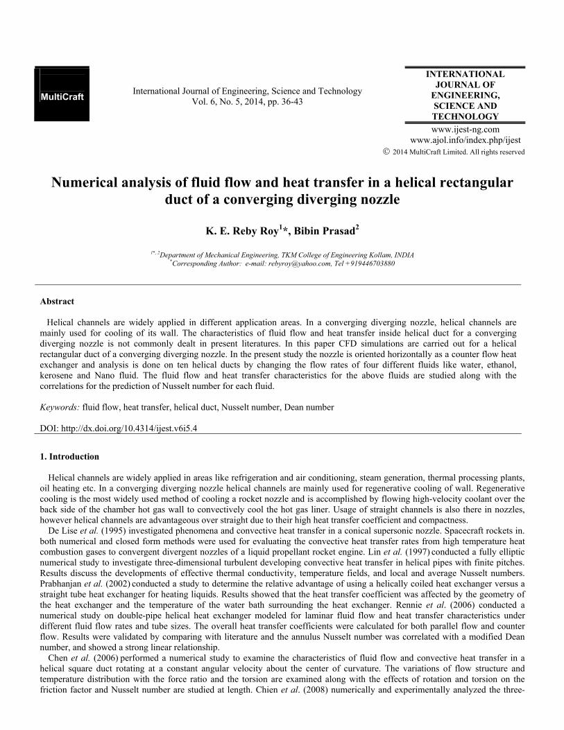
Most of the studies of helical channels are examined on cylindrical volumes by wounding circular tubes. The objective of this paper is to study heat transfer and fluid flow in a helical rectangular duct of a converging diverging nozzle. The results were interpreted by predicting correlation between Nusselt number and Dean number.
Figure.1 (a) Nozzle with helical ducts covered by outer shell. (b) Nozzle wounded by 10 helical ducts.
2. Computational resource description
Three dimensional physical models for fluid analysis is made in AUTOCAD 2010 and exported as sat file to Gambit 2.4.6 for mesh generation as shown in Figure 1. Boundary layer mesh was generated for both nozzle and helix. Meshed model is then exported to Fluent 6.3.26 for analysis. A HP xw6600 workstation having following configuration is used - Processor- Intel(R) Xeon(R) CPU, RAM- 8GB, Hard Disc- 250GB 3. CFD model for heat transfer in nozzle and helix
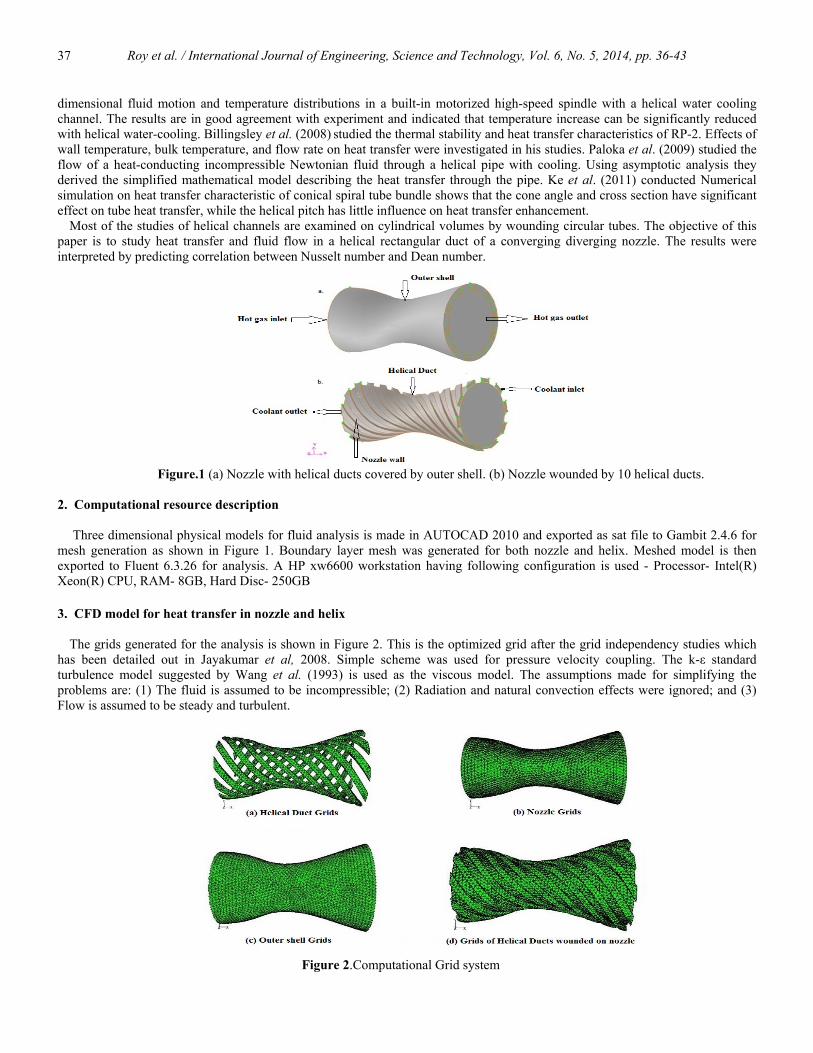
The grids generated for the analysis is shown in Figure 2. This is the optimized grid after the grid independency studies which has been detailed out in Jayakumar et al, 2008. Simple scheme was used for pressure velocity coupling. The k-ε standard turbulence model suggested by Wang et al. (1993) is used as the viscous model. The assumptions made for simplifying the problems are: (1) The fluid is assumed to be incompressible; (2) Radiation and natural convection effects were ignored; and (3) Flow is assumed to be steady and turbulent.
Figure 2.Computational Grid system
Roy et al. / International Journal of Engineering, Science and Technology, Vol. 6, No. 5, 2014, pp. 36-43
38
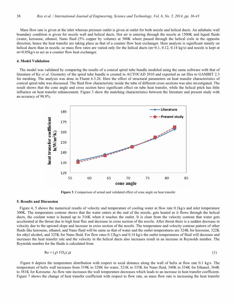
Mass flow rate is given at the inlet whereas pressure outlet is given at outlet for both nozzle and helical ducts. An adiabatic wall boundary condition is given for nozzle wall and helical ducts. Hot air is entering through the nozzle at 1500K and liquid fluids (water, kerosene, ethanol, Nano fluid (5% copper by volume) at 300K where passed through the helical coils in the opposite direction, hence the heat transfer are taking place as that of a counter flow heat exchanger. Here analysis is significant mainly on helical ducts than in nozzle, so mass flow rates are varied only for the helical ducts (m=0.1, 0.12, 0.14 kg/s) and nozzle is kept at m=0.05kg/s to act as a counter flow heat exchanger. 4. Model Validation The model was validated by comparing the results of a conical spiral tube bundle modeled using the same software with that of literature of Ke et al. Geometry of the spiral tube bundle is created in AUTOCAD 2010 and exported as sat files to GAMBIT 2.3 for meshing. The analysis was done in Fluent 6.3.26. Here the effect of structural parameters on heat transfer characteristics of conical spiral tube was discussed. The fluid flow characteristic inside the tube of different cross sections was also investigated. The result shows that the cone angle and cross section have significant effect on tube heat transfer, while the helical pitch has little influence on heat transfer enhancement. Figure 3 show the matching characteristics between the literature and present study with an accuracy of 98.8%.
Figure 3. Comparison of actual and validated effect of cone angle on heat transfer
5. Results and Discussion
Figure 4, 5 shows the numerical results of velocity and temperature of cooling water at flow rate 0.1kg/s and inlet temperature 300K. The temperature contour shows that the water enters at the end of the nozzle, gets heated as it flows through the helical ducts, the coolant water is heated up to 316K when it reaches the outlet. It is clear from the velocity contour that water gets accelerated at the throat due to high heat flux and decrease in cross section of the nozzle. After throat there is a sudden decrease in velocity due to the upward slope and increase in cross section of the nozzle. The temperature and velocity contour pattern of other fluids like kerosene, ethanol, and Nano fluid will be same as that of water and the outlet temperatures are 324K for kerosene, 322K for ethyl alcohol, and 325K for Nano fluid. For flow rates 0.12kg/s and 0.14 kg/s the outlet temperatures of fluid will decrease and increases the heat transfer rate and the velocity in the helical ducts also increases result in an increase in Reynolds number. The Reynolds number for the fluids is calculated from
Re = ( ρ VDh)/µ (1)
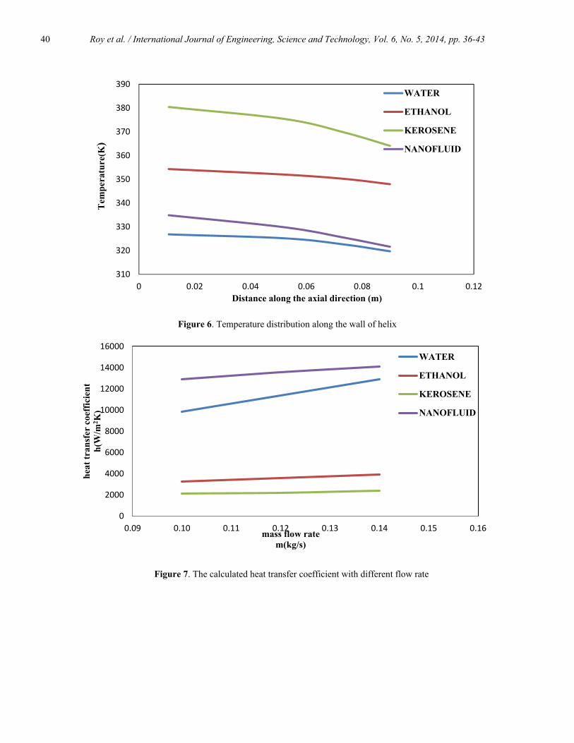
Figure 6 depicts the temperature distribution with respect to axial distance along the wall of helix at flow rate 0.1 kg/s. The
temperature of helix wall increases from 319K to 328K for water, 321K to 335K for Nano fluid, 348K to 354K for Ethanol, 364K to 381K for Kerosene. As flow rate increases the wall temperature decreases which leads to an increase in heat transfer coefficient. Figure 7 shows the change of heat transfer coefficient with respect to flow rate, as mass flow rate is increasing the heat transfer

Roy et al. / International Journal of Engineering, Science and Technology, Vol. 6, No. 5, 2014, pp. 36-43
39
coefficient also increases due to decrease in bulk temperature of fluid and average wall temperature of helical duct. Heat transfer coefficient for the fluids is calculated by the relation
h = Q/A(Tw – Tb) (2)
Heat transfer coefficient of Nano fluid is found 68.6% greater than kerosene, 39.1% greater than ethanol and 11.9% greater than water. Figure 8 illustrates the temperature contours of nozzle along a vertical plane. It is shown that the hot gas temperature is decreasing when expands through the nozzle throat. The nozzle wall temperature is found out to be decreasing as coolant is flowing from other side. At hot gas temperature 1500K it’s found that the average wall temperature of nozzle is found in the range of 500K without cooling and at a flow rate of 0.1kg/s the average temperature is in the range of 324K with water cooling, 375K with kerosene, 352K with ethanol and 328Kwith Nano Fluid. The average outlet temperature of nozzle is in the range of 1320K for Nano fluid, 1370K for water, 1374K for Ethanol and 1377K for Kerosene. As flow rates increases there will be a decrease in nozzle average wall temperature and outlet temperature.
Figure 4. Temperature contours of Fluids at m = 0.1kg/s
Figure 5. Velocity contours of Fluids at m=0.1kg/s
Roy et al. / International Journal of Engineering, Science and Technology, Vol. 6, No. 5, 2014, pp. 36-43
40
310
320
330
340
350
360
370
380
390
0 0.02 0.04 0.06 0.08 0.1 0.12
Tem
pera
ture
(K)
Distance along the axial direction (m)
WATER
ETHANOL
KEROSENE
NANOFLUID
Figure 6. Temperature distribution along the wall of helix
0
2000
4000
6000
8000
10000
12000
14000
16000
0.09 0.10 0.11 0.12 0.13 0.14 0.15 0.16
heat
tran
sfer
coe
ffic
ient
h(
W/m
2 K)
mass flow ratem(kg/s)
WATER
ETHANOL
KEROSENE
NANOFLUID
Figure 7. The calculated heat transfer coefficient with different flow rate

Roy et al. / International Journal of Engineering, Science and Technology, Vol. 6, No. 5, 2014, pp. 36-43
41
Figure 8. Temperature contours of hot gas along a vertical plane at m=0.05kg/s using different coolant Figure 9 depicts the temperature variation in the nozzle wall using different coolants. It can be seen that Nano Fluid keeps the
nozzle wall section cooler than other fluids followed by Water, Ethanol and Kerosene. In rocket applications, a part of the fuel example Kerosene is bypassed to act as a coolant. Here the advantage lies in the fact that separate investment for another coolant is avoided. However using a coolant such as Nano Fluid (5% Cu by volume) gives a high heat transfer rate and thus the gain obtained is much higher than the investment involved.
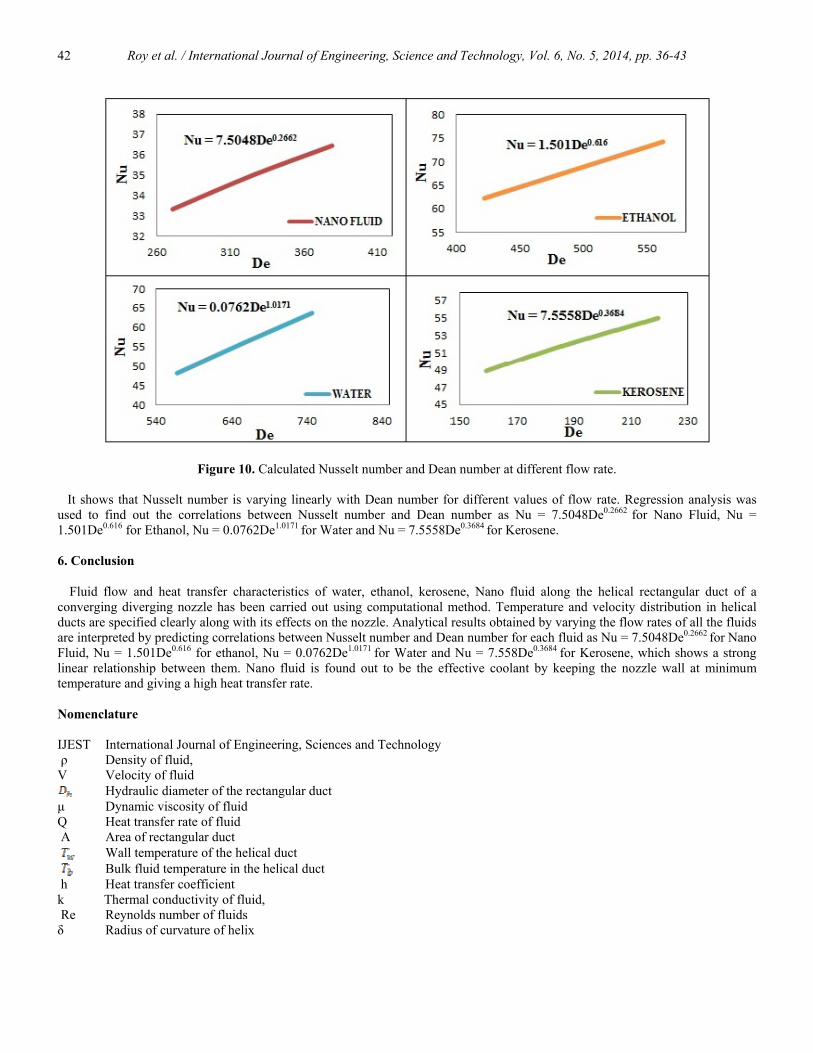
Figure 10 illustrates the calculated values of Nusselt number with Dean number for water, ethanol, kerosene and Nano fluid. The Nusselt number and Dean number is tabulated by using the relations
(3)
and (4)
Figure 9. Temperature distribution in the nozzle wall using different coolants
Roy et al. / International Journal of Engineering, Science and Technology, Vol. 6, No. 5, 2014, pp. 36-43
42
Figure 10. Calculated Nusselt number and Dean number at different flow rate. It shows that Nusselt number is varying linearly with Dean number for different values of flow rate. Regression analysis was used to find out the correlations between Nusselt number and Dean number as Nu = 7.5048De0.2662 for Nano Fluid, Nu = 1.501De0.616 for Ethanol, Nu = 0.0762De1.0171 for Water and Nu = 7.5558De0.3684 for Kerosene. 6. Conclusion
Fluid flow and heat transfer characteristics of water, ethanol, kerosene, Nano fluid along the helical rectangular duct of a converging diverging nozzle has been carried out using computational method. Temperature and velocity distribution in helical ducts are specified clearly along with its effects on the nozzle. Analytical results obtained by varying the flow rates of all the fluids are interpreted by predicting correlations between Nusselt number and Dean number for each fluid as Nu = 7.5048De0.2662 for Nano Fluid, Nu = 1.501De0.616 for ethanol, Nu = 0.0762De1.0171 for Water and Nu = 7.558De0.3684 for Kerosene, which shows a strong linear relationship between them. Nano fluid is found out to be the effective coolant by keeping the nozzle wall at minimum temperature and giving a high heat transfer rate. Nomenclature IJEST International Journal of Engineering, Sciences and Technology ρ Density of fluid, V Velocity of fluid
Hydraulic diameter of the rectangular duct µ Dynamic viscosity of fluid Q Heat transfer rate of fluid A Area of rectangular duct Wall temperature of the helical duct Bulk fluid temperature in the helical duct h Heat transfer coefficient k Thermal conductivity of fluid, Re Reynolds number of fluids δ Radius of curvature of helix
Roy et al. / International Journal of Engineering, Science and Technology, Vol. 6, No. 5, 2014, pp. 36-43
43
References
Chien C.H., Jang J.Y., 2008. 3-D numerical and experimental analysis of a built-in motorized High-speed spindle with helical water cooling channel, Applied Thermal Engineering, Vol. 28, pp. 2327-2336.
Lin C. X. and Ebadian M. A. 1997, Developing turbulent convective heat transfer in helical pipes, International Journal of Heat and Mass Transfer, Vol. 40. No. 16, m. 3861-3873.
Prabhanjan D. G., Raghavan G. S. V. and Kennic T. J., 2002 Comparison of heat transfer rates between a straight tube heat exchanger and a helically coiled heat exchanger, International Communication in Heat and Mass Transfer, Vol. 29. No. 2. pp. 185-191.
Marusic-Paloka E., Pazanin I., 2009. Modelling of heat transfer in a laminar flow through a helical pipe, Mathematical and Computer Modelling, Vol. 50, pp. 1571-1582
De Lise J.C. and Naraghi M.H. 1995, Comapative study of convective heat transfer models for rocket engines, AIAA95-2499,31stAIAA/ASME/SAE?ASEE Joint Propulsion Conference.1995, San Diago
Jayakumara J.S., Mahajania S.M., Mandal J.C., Iyer K.N., Vijayan P.K.. 2010. CFD analysis of single-phase flows inside helically coiled tubes, Computers and Chemical Engineering, Vol. 34, pp. 430–446
Billingsley M.C., 2008. Thermal stability and heat transfer characteristics of RP-2., AIAA 2008-5126, AIAA Joint Propulsion Conference.
Kharat R., Bhardwaj N., Jha R.S., 2009. Development of heat transfer coefficient correlation for concentric helical coil heat exchanger, International Journal of Thermal Sciences, Vol. 48, pp. 2300-2308
Rennie T.J., Raghavan V.G.S., 2006. Numerical studies of a double-pipe helical heat exchanger, Applied Thermal Engineering,, Vol. 26, pp. 1266–1273
Wang T.S., Chen Y.S. 1993, Unified Navier–Stokes flow field and performance analysis of liquid rocket engines, AIAA Journal Vol. 9, pp. 678–685.
Yan K., Ge P.-Q., Su Y.-C., Meng H.-T., 2011. Numerical simulation on heat transfer characteristic of conical spiral tube bundle, Applied Thermal Engineering, Vol. 31, pp. 284-292
Chen Y., Chen H., Zhang B., Hsieh H.-T. 2006, Fluid flow and convective heat transfer in a rotating helical square duct, International Journal of Thermal Sciences, Vol. 45, pp. 1008-1020
Biographical notes K.E. Reby Roy received Ph.D. from Indian Institute of Technology Madras, India in 2003. He is an Assistant Professor in the Department of Mechanical Engineering, TKM College of Engineering Kollam, India. His research interests include Computational Fluid Dynamics, Cryogenic Engineering, Refrigeration, Heat Transfer, Finite Element Analysis. Bibin Prasad is an M.Tech scholar (2009 batch) in the Department of Mechanical Engineering, TKM College of Engineering Kollam, India. His areas of research includes Computational Fluid Dynamics, Heat transfer, Microfluidics and Cryogenics. Received March 2012 Accepted May 2014 Final acceptance in revised form August 2014


![Numerical Heat Transfer and Fluid FLow [Patankar]](https://static.fdocuments.us/doc/165x107/55cf8fea550346703ba13647/numerical-heat-transfer-and-fluid-flow-patankar-569a3a8a8d259.jpg)