A numerical study of heat transfer and fluid flow over … · A numerical study of heat transfer...
12
A numerical study of heat transfer and fluid flow over an in-line tube bank Z. S. Abdel-Rehim Mechanical Engineering Department, National Research Center, Egypt Abstract Heat transfer and fluid flow over an in-line tube bank using a computational fluid dynamic (CFD) prediction is presented in this study. The study considers steady laminar two-dimensional incompressible flow over in-line tube bundles used in heat exchanger applications. The effect of various independent parameters, such as Reynolds number (Re), length aspect ratio (L/D = 2.5, 2, 1.5, 1.0, 0.5 and 0.0), and fluid flow on the pressure drop and heat transfer is studied. A computer code (CFD-Fluent) is used, generally, to predict the heat transfer and pressure drop characteristics of flows around or through rigid complex geometry, namely domains whose boundaries do not coincide with coordinate lines of a Cartesian or any simple coordinate system. A comparison is made between the present CFD predictions and reference measurements (Iwaki, et al. PIV Measurement of Vertical Cross Flow Structure over Tube Bundles, Experiments in Fluids, 2004) for the velocity vector as fluid flow over a cylinder in cross flow for the selected values of Reynolds numbers Re D . Therefore, the comparison is made between the present CFD results and Martin empirical correlation of an in-line circular tube for the variation of Nu with Re D . A reasonable agreement is observed. The results of the present study provide sufficient confidence in using empirical correlations to undertake initial sizing of tube bank heat exchanger design, with thermo-fluid performance subsequently predicted by CFD analysis for specific requirement applications. Keywords: CFD prediction, fluid flow, in-line arrangement, laminar flow, length aspect ratio, tube bank. 1 Introduction Heat transfer enhancement is the process of improving the performance of a heat transfer system by increasing the heat transfer coefficient. Flat tubes have not Fluid Structure Interaction VI 295 www.witpress.com, ISSN 1743-3509 (on-line) WIT Transactions on The Built Environment, Vol 115, © 2011 WIT Press doi:10.2495/ 11 FSI 0251
Transcript of A numerical study of heat transfer and fluid flow over … · A numerical study of heat transfer...
A numerical study of heat transfer and fluid flow over an in-line tube bank
Z. S. Abdel-Rehim Mechanical Engineering Department, National Research Center, Egypt
Abstract
Heat transfer and fluid flow over an in-line tube bank using a computational fluid dynamic (CFD) prediction is presented in this study. The study considers steady laminar two-dimensional incompressible flow over in-line tube bundles used in heat exchanger applications. The effect of various independent parameters, such as Reynolds number (Re), length aspect ratio (L/D = 2.5, 2, 1.5, 1.0, 0.5 and 0.0), and fluid flow on the pressure drop and heat transfer is studied. A computer code (CFD-Fluent) is used, generally, to predict the heat transfer and pressure drop characteristics of flows around or through rigid complex geometry, namely domains whose boundaries do not coincide with coordinate lines of a Cartesian or any simple coordinate system. A comparison is made between the present CFD predictions and reference measurements (Iwaki, et al. PIV Measurement of Vertical Cross Flow Structure over Tube Bundles, Experiments in Fluids, 2004) for the velocity vector as fluid flow over a cylinder in cross flow for the selected values of Reynolds numbers ReD. Therefore, the comparison is made between the present CFD results and Martin empirical correlation of an in-line circular tube for the variation of Nu with ReD. A reasonable agreement is observed. The results of the present study provide sufficient confidence in using empirical correlations to undertake initial sizing of tube bank heat exchanger design, with thermo-fluid performance subsequently predicted by CFD analysis for specific requirement applications. Keywords: CFD prediction, fluid flow, in-line arrangement, laminar flow, length aspect ratio, tube bank.
1 Introduction
Heat transfer enhancement is the process of improving the performance of a heat transfer system by increasing the heat transfer coefficient. Flat tubes have not
Fluid Structure Interaction VI 295
www.witpress.com, ISSN 1743-3509 (on-line) WIT Transactions on The Built Environment, Vol 115, © 2011 WIT Press
doi:10.2495/ 11FSI 0251

been investigated to the same extent, although they play an important role in many technical applications such as, modern heat exchangers, automotive radiators, air conditioning evaporators and condensers (Webb [1]). Finite volume techniques are increasingly being used for computing incompressible flow in arbitrary geometries because of the recent developments in grid generation methods. An Introduction to Computational Fluid Dynamics the Finite Volume Method (Versteeg and Malalasekera [2]). Grid generation within two- and three-dimensional spaces is considerably more complicated than one-dimensional grid generation (Hoffman [3]). Most studies were concerned with the flow over a circular cylinder (Williamson 1996 and Zdrakovich [4]). Extensive numerical based studies have been undertaken to investigate the fluid flow and heat transfer in tube banks (Fujii et al. [5]). The main objective of this work is to develop a computer code to predict the heat transfer and pressure drop characteristics of flow (for simplicity) through one vertical row of in-line alignment of tube bank. The present study considers steady laminar two-dimensional incompressible flow past tube found in heat exchanger applications. The main purpose of this work is to study the effect of different length aspect ratios (L/D = 2.5, 2, 1.5, 1.0, 0.5 and 0.0) and Reynolds numbers of the fluid on pressure drop and heat transfer. The results present the grid, residual, static pressure, static temperature and velocity vector for the selected cases at the same conditions, assumptions and the values of Reynolds numbers. A comparison is made between the present CFD predictions and reference measurements (Iwaki et al. [6]) for the velocity vector and magnitude as fluid flow over a cylinder in cross flow for the selected values of Reynolds numbers ReD. Also, the comparison is made between the present CFD results and Martin empirical correlation of in-line circular tube for the variation of Nu with ReD.
2 Governing equations and solution method
The differential equations governing the conservation of mass, momentum, and energy can be cast into a general form as:
SJ
t
)( (1)
where t is time, second
where
VJ (2)
yX ey
VeX
UJ (3)
In these equations, φ is a general dependent variable (φU, V, p and T), ρ is
the mass density kg.m-3, is the effective diffusion coefficient, V
is the velocity
vector, and S designates the volumetric source (or sink) of φ. In Eqn. (2) J
corresponds to the total flux W/m2 of φ, i.e., it takes account of both the
296 Fluid Structure Interaction VI
www.witpress.com, ISSN 1743-3509 (on-line) WIT Transactions on The Built Environment, Vol 115, © 2011 WIT Press
convective and diffusive fluxes. For convenience, expressions in the Cartesian vector notation for steady-state incompressible flow are given below.
Continuity: 0.0U V
x y
(4)
where U, V are Cartesian components of fluid velocity, m.s-1 and x, y are Cartesian coordinates.
Momentum:
VPVV 2).( (5)
where P is pressure drop, pa and is dynamic viscosity, N.s.m-2.
Momentum Equation in Two Directions:
2 2
2 2
( ) ( ) 1
R e
U U U V P U V
x y x x y
(6)
2 2
2 2
( ) ( ) 1
R e
U V V V P U V
x y y x y
(7)
where Re is Reynolds number (= V Dh / )
Energy: TkTVC P2).(
(8)
where Cp is specific heat, J.kg-1.K-1, T is temperature, K and k is thermal conductivity, W. m-1. K-1
y
V
x
U
y
VT
x
UT2
2
2
2
PrRe
1)()( (9)
where Pr is Prandtl number (= Cp /k) = 0.7 (air)
Wall Boundary Conditions, the most common boundary condition that comes across in a confined fluid flow problem is the wall boundary condition. The no-slip condition, valid for viscous flows, can be enforced for the velocities. Consequently, the velocity of the fluid at the wall must be equal to the velocity of the wall (i.e., zero in most of the cases). Eqns. (4)–(9) above are referred to as the Navier–Stokes equation for the general constant property incompressible flow of a Newtonian fluid. The Navier–Stokes equation in the above form constitute a system of two equations
(in two-dimensional flow) with two unknowns, P and V
. Solution method, the in-line, implicit solver is used to solve the governing differential equations for the conservation of the mass, momentum and energy equations.
3 Mathematical assumptions
– The flow is two-dimensional, steady, laminar and incompressible.
Fluid Structure Interaction VI 297
www.witpress.com, ISSN 1743-3509 (on-line) WIT Transactions on The Built Environment, Vol 115, © 2011 WIT Press
– The thickness of the tube is neglected. – The thermo-physical properties of the fluid do not vary with temperature. – The viscous heating is neglected.
4 Control volume formulations
The first step to derive the discretized equation from the general conservation equation is to divide the computational domain into a set of non-overlapping control volumes then the conservation equations are expressed in an integral form in each of these control volumes. The advantage of this control volume approach is to preserve the conservation property, which is important for engineering applications in which the overall balance of mass, momentum, and energy are usually of major significance. The formulation presented here is identical to the formulation proposed by Karki [7]. The computational domain, in two-dimension, is divided into quadrilateral volumes by using any of the grid generation techniques. A Numerical study of heat and momentum transfer over flat tubes is presented by Haitham and Bahaidarah [8].
5 Structured grids
Two-dimensional, steady state form of the generalized Eqn. (1) is discretized as:
SJ
. (10)
This equation will be discretized in terms of fluxes. Then, the general transport equation for property φ is derived by using a proper profile assumption. The control volume integration, which represents the main step of the finite volume technique, yields the following form:
V
X
A
VdSSdeJ . (11)
where V is the volume of a curvilinear element with a fixed boundary and eX is
a general unit normal vector in one cell face.
6 Geometry, grid distribution and boundary conditions for in-line configuration
Figure 1 shows the grid configuration, initial, boundary conditions and control volume of the present model. In this study, (for simplicity), one vertical row of in-line tube bank and four tubes are included in the computational domain. The computational domain was divided into three individual regions as; entry region, tube module and exit region. A uniform orthogonal grid was used for both entry and exit regions. Where D is diameter, m, H is height of control volume, m and L is length, m. The surfaces BC and FG are the top wall of the lower tube and the bottom wall of the upper tube, respectively. A no-slip boundary condition was assigned for
298 Fluid Structure Interaction VI
www.witpress.com, ISSN 1743-3509 (on-line) WIT Transactions on The Built Environment, Vol 115, © 2011 WIT Press

these two surfaces. The lines AB, CD, EF, and GH are lines of symmetry where no flow crosses these boundaries and the normal component of velocities and the normal gradient of the parallel component of velocity are set to zero. Finally, the lines AH and DE are recognized as the module inlet and module outlet, respectively. Figure 2 shows the model of length aspect ratio.
BC: surface of top wall of the lower tube FG: surface of bottom wall of the upper tube
Vertical one row, control volume and initial conditions
AB, CD, EF and GH: lines of symmetry AH: line of module inlet DE: line of module outlet
Figure 1: Grid configuration, initial and boundary conditions and control volume of the present model.
Figure 2: Model of length aspect ratio.
7 Correlations
Martin [9] developed a comprehensive convective heat transfer correlations for in-line tube banks, in terms of Lévêque number, Lq (= 0.5 XT Hg pr Dh / L), where with Nusselt number as:
1.0
3
1
1000Re
1Re404.0
D
DLqNu (12)
Although the correlations have been developed for the predication of the local Nu (= h Dh /k), the importance lies in the overall average heat transfer coefficient. The empirical correlation proposed by Hilpert [10] for the overall Nu is widely used:
Fluid Structure Interaction VI 299
www.witpress.com, ISSN 1743-3509 (on-line) WIT Transactions on The Built Environment, Vol 115, © 2011 WIT Press
3
1
Pr.Re. mDD C
k
DhuN
(13)
where C and m are the model constants. An alternative correlation for convective heat transfer from cylinders of low aspect ratio in the limit of the same form was proposed by Zhukauskas [11].
8 Results and discussions
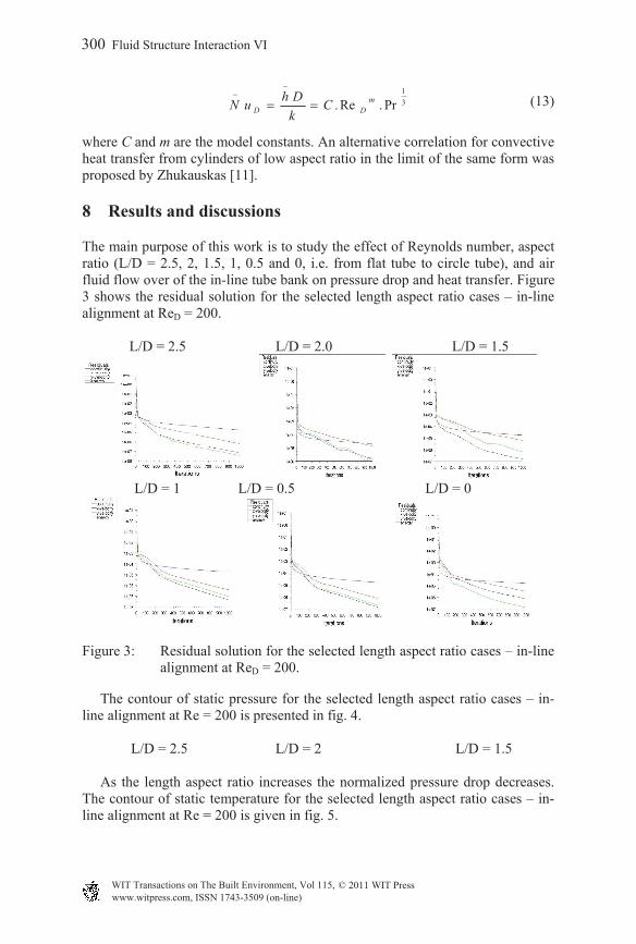
The main purpose of this work is to study the effect of Reynolds number, aspect ratio (L/D = 2.5, 2, 1.5, 1, 0.5 and 0, i.e. from flat tube to circle tube), and air fluid flow over of the in-line tube bank on pressure drop and heat transfer. Figure 3 shows the residual solution for the selected length aspect ratio cases – in-line alignment at ReD = 200. L/D = 2.5 L/D = 2.0 L/D = 1.5
L/D = 1 L/D = 0.5 L/D = 0
Figure 3: Residual solution for the selected length aspect ratio cases – in-line alignment at ReD = 200.
The contour of static pressure for the selected length aspect ratio cases – in-line alignment at Re = 200 is presented in fig. 4.
L/D = 2.5 L/D = 2 L/D = 1.5 As the length aspect ratio increases the normalized pressure drop decreases. The contour of static temperature for the selected length aspect ratio cases – in-line alignment at Re = 200 is given in fig. 5.
300 Fluid Structure Interaction VI
www.witpress.com, ISSN 1743-3509 (on-line) WIT Transactions on The Built Environment, Vol 115, © 2011 WIT Press
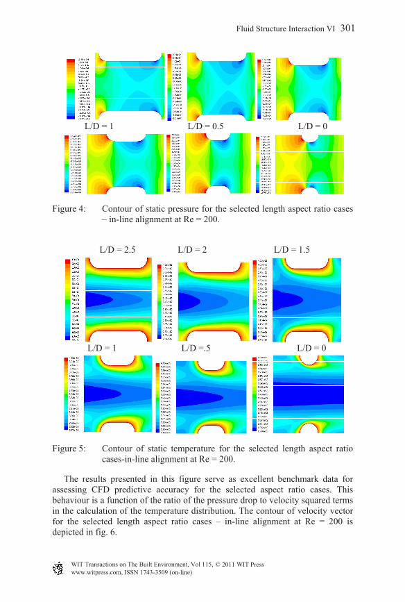
L/D = 1 L/D = 0.5 L/D = 0
Figure 4: Contour of static pressure for the selected length aspect ratio cases – in-line alignment at Re = 200.
L/D = 2.5 L/D = 2 L/D = 1.5
L/D = 1 L/D =.5 L/D = 0
Figure 5: Contour of static temperature for the selected length aspect ratio cases-in-line alignment at Re = 200.
The results presented in this figure serve as excellent benchmark data for assessing CFD predictive accuracy for the selected aspect ratio cases. This behaviour is a function of the ratio of the pressure drop to velocity squared terms in the calculation of the temperature distribution. The contour of velocity vector for the selected length aspect ratio cases – in-line alignment at Re = 200 is depicted in fig. 6.
Fluid Structure Interaction VI 301
www.witpress.com, ISSN 1743-3509 (on-line) WIT Transactions on The Built Environment, Vol 115, © 2011 WIT Press
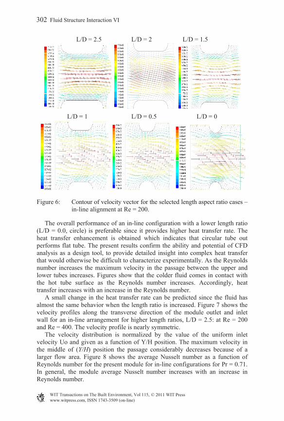
L/D = 2.5 L/D = 2 L/D = 1.5
L/D = 1 L/D = 0.5 L/D = 0
Figure 6: Contour of velocity vector for the selected length aspect ratio cases – in-line alignment at Re = 200.
The overall performance of an in-line configuration with a lower length ratio (L/D = 0.0, circle) is preferable since it provides higher heat transfer rate. The heat transfer enhancement is obtained which indicates that circular tube out performs flat tube. The present results confirm the ability and potential of CFD analysis as a design tool, to provide detailed insight into complex heat transfer that would otherwise be difficult to characterize experimentally. As the Reynolds number increases the maximum velocity in the passage between the upper and lower tubes increases. Figures show that the colder fluid comes in contact with the hot tube surface as the Reynolds number increases. Accordingly, heat transfer increases with an increase in the Reynolds number. A small change in the heat transfer rate can be predicted since the fluid has almost the same behavior when the length ratio is increased. Figure 7 shows the velocity profiles along the transverse direction of the module outlet and inlet wall for an in-line arrangement for higher length ratios, L/D = 2.5: at Re = 200 and Re = 400. The velocity profile is nearly symmetric. The velocity distribution is normalized by the value of the uniform inlet velocity Uo and given as a function of Y/H position. The maximum velocity in the middle of (Y/H) position the passage considerably decreases because of a larger flow area. Figure 8 shows the average Nusselt number as a function of Reynolds number for the present module for in-line configurations for Pr = 0.71. In general, the module average Nusselt number increases with an increase in Reynolds number.
302 Fluid Structure Interaction VI
www.witpress.com, ISSN 1743-3509 (on-line) WIT Transactions on The Built Environment, Vol 115, © 2011 WIT Press

(a) (b)
Figure 7: The developing velocity profiles along the transverse direction of the module outlet and the inlet wall for an in-line arrangement: a (Re = 200) and b (Re = 400).
Aspect ratio
Figure 8: Effect of length aspect ratio on the average Nusselt number for the present module, Pr = 0.71, for in-line arrangements for L/D = 2.5 for Re = 200 and Re = 400.
Figure 9 provides the normalized pressure drop for the present module for in-line configurations for Re = 200 and Re = 400. It shows the impact of length ratio on the normalized pressure drop. It can be clearly stated that the length ratio has very little effect on pressure drop except for L/D = 0.
Fluid Structure Interaction VI 303
www.witpress.com, ISSN 1743-3509 (on-line) WIT Transactions on The Built Environment, Vol 115, © 2011 WIT Press
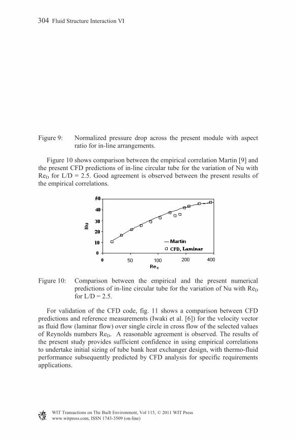
Figure 9: Normalized pressure drop across the present module with aspect ratio for in-line arrangements.
Figure 10 shows comparison between the empirical correlation Martin [9] and the present CFD predictions of in-line circular tube for the variation of Nu with ReD for L/D = 2.5. Good agreement is observed between the present results of the empirical correlations.
Figure 10: Comparison between the empirical and the present numerical predictions of in-line circular tube for the variation of Nu with ReD for L/D = 2.5.
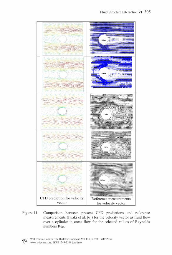
For validation of the CFD code, fig. 11 shows a comparison between CFD predictions and reference measurements (Iwaki et al. [6]) for the velocity vector as fluid flow (laminar flow) over single circle in cross flow of the selected values of Reynolds numbers ReD. A reasonable agreement is observed. The results of the present study provides sufficient confidence in using empirical correlations to undertake initial sizing of tube bank heat exchanger design, with thermo-fluid performance subsequently predicted by CFD analysis for specific requirements applications.
304 Fluid Structure Interaction VI
www.witpress.com, ISSN 1743-3509 (on-line) WIT Transactions on The Built Environment, Vol 115, © 2011 WIT Press
CFD prediction for velocity
vector
Reference measurements
for velocity vector
Figure 11: Comparison between present CFD predictions and reference measurements (Iwaki et al. [6]) for the velocity vector as fluid flow over a cylinder in cross flow for the selected values of Reynolds numbers ReD.
Fluid Structure Interaction VI 305
www.witpress.com, ISSN 1743-3509 (on-line) WIT Transactions on The Built Environment, Vol 115, © 2011 WIT Press

9 Conclusions
1. On comparing CFD predictions with empirical correlations for tube bank convective heat transfer and pressure drop for Re range 50 to 400, good agreement is found with the empirical correlations developed by Martin [9] for heat transfer. Such agreement provides sufficient confidence in using empirical correlations to undertake initial sizing of tube bank heat exchanger design, with thermo fluid performance subsequently by CFD analysis for specific requirements applications.
2. A small change in the heat transfer rate can be predicted since the fluid has almost the same behavior when the length ratio is increased.
3. The length ratio was found to have very little effect on pressure. 4. The maximum velocity in the middle of (Y/H) position as the passage
considerably decreases because of a larger flow area.
References
[1] Webb, R.L., Principles of enhanced heat transfer, John Wiley and Sons, Inc.: New York, 1993.
[2] Versteeg, H.K., Malalasekera, W., An introduction to computational fluid dynamics the finite volume method, Longman Scientific and Technical: New York, 1995.
[3] Hoffman, J.D., Numerical methods for engineers and Scientists, McGraw-Hill, Inc.: New York, 1992.
[4] Zdrakovich, M.M., Flow around circular cylinders, 1: Fundamental, Oxford University Press: New York, 1997.
[5] Fujii, M., and Fujii, T., A Numerical Analysis of Laminar Flow and Heat Transfer of Air in an In-Line Tube Bank. Numerical Heat Transfer, (7), pp. 89-102, 1984.
[6] Iwaki, C., Cheong, K.H., Monji, H., and Matsui, G., PIV Measurement of Vertical Cross Flow Structure over Tube Bundles, Experiments in Fluids, (37), pp. 350-363, 2004 .
[7] Karki, K., A calculation procedure for viscous flows at all speeds in complex geometries, Ph. D. Dissertation, University of Minnesota, 1986.
[8] Haitham M. S. Bahaidarah, A Numerical study of heat and momentum transfer over flat tubes, PhD Thesis, Texas A&M University, August 2004.
[9] Martin, H., The Generalized Lévêque Equation and its Practical Use for the Prediction of Heat and Mass Transfer Rates From Pressure Drop, Chemical Energy, SCI., (57), pp. 3217-3223, 2002.
[10] Hilpert, R., Warmeabgabe Von geheizten Drahten und Rohren, Forsch. Geb. Ingenieurwes, (4), pp. 215-224, 1933.
[11] Zhukauskas, A., Heat Transfer from Tubes in Cross Flow, Advances in Heat Transfer, (8), pp.93-160, 1972.
306 Fluid Structure Interaction VI
www.witpress.com, ISSN 1743-3509 (on-line) WIT Transactions on The Built Environment, Vol 115, © 2011 WIT Press