Numerical Simulation of Fluid Flow and Heat Transfer in a ... · PDF fileNumerical Simulation...
6
Numerical Simulation of Fluid Flow and Heat Transfer in a Plasma Cutting Torch ASAD A.SALEM College of Science & Technology Texas A&M University- Corpus Christi Corpus Christi, TX 78412-5797 USA Abstract: A computational fluid dynamics (CFD) simulation for analyzing heat transfer and fluid flow patterns in a plasma cutting torch is presented in this study. Based on CFD and heat transfer theory, the numerical model of the nozzle in the plasma cutting torch is developed, and the coupled simulation of the flow fluid and heat transfer is carried out with the semi-implicit method for pressure-linked equations (SIMPLE) method. The distributions of the current density, velocity and temperature in the plasma cutting torch, and the torch’s pressure are demonstrated. The present study provides a new means of research in this filed, which could be helpful in the future of plasma cutting and welding torches. Key-words: - Fluid field · Heat transfer · Numerical simulation · Plasma Cutting Torch 1. Introduction The Plasma Arc Cutting, which is one of the applications of Arc Cutting Processes, is widely used to rapidly cut ferrous and nonferrous materials [1]. The temperatures generated are very high (9000 o C; in the torch for oxygen as a plasma gas). Consequently, the process is rapid, parts as thick as 125 mm can be cut with excellent surface finish, and very small kerf width. Material- removal rates are high, and parts can be machined with good reproducibility. In order to obtain high-quality cuts, it is necessary to develop a plasma torch with excellent performance, i.e., a long service life, high speeds, and a stable plasma arc. A high-quality cut requires a thin, hot and high-velocity plasma jet. The plasma is created by a narrow constricting nozzle inside the torch, into which the gas-plasma system is injected at a high pressure. The fineness of the nozzle creates a large voltage drop in the plasma along its length, providing intense heating of the plasma –gas and associated pressure gradient forces, which accelerate the fluids to large velocities [2]. The development of a plasma cutting torch is based, largely, on an experimental optimization of the device. Therefore, in this respect, plasma modeling is an important tool to confront with experimental measurement to reduce the amount of experimental work used for design optimization. The study of heat transfer and fluid flow in the weld pool has been an area of active research in recent years, and it is now well recognized that fluid dynamics and heat transfer considerations can significantly affect the shape, microstructure and mechanical properties of the resultant weld [3]. Although plasma metal cutting and welding processes have had a widespread industrial application and development, only recently their plasma properties and characteristics have received attention. Ramakrishnan et al [4, 5] experimentally measured the arc voltage, the cathode nozzle voltage, the gas pressure at the nozzle’s entrance and the diameter of the plasma jet emerging from the nozzle as functions of the torch arc current. Nemchinsky [6] presented a detailed model to describe the plasma-gas flow in the nozzle. In this model the author presented a simplified two-zone fluid model in which, owing to strong dependence of the gas conductivity with the gas temperature, all current is assumed to circulate through a hot central core inside the nozzle. In his model, Nemchinsky assumed that the cold gas to evolve isothermally and the arc Proceedings of the 2006 WSEAS/IASME International Conference on Fluid Mechanics, Miami, Florida, USA, January 18-20, 2006 (pp19-24)
Transcript of Numerical Simulation of Fluid Flow and Heat Transfer in a ... · PDF fileNumerical Simulation...
Numerical Simulation of Fluid Flow and Heat Transfer in a Plasma Cutting
Torch
ASAD A.SALEM College of Science & Technology
Texas A&M University- Corpus Christi Corpus Christi, TX 78412-5797
USA
Abstract: A computational fluid dynamics (CFD) simulation for analyzing heat transfer and fluid flow patterns in a plasma cutting torch is presented in this study. Based on CFD and heat transfer theory, the numerical model of the nozzle in the plasma cutting torch is developed, and the coupled simulation of the flow fluid and heat transfer is carried out with the semi-implicit method for pressure-linked equations (SIMPLE) method. The distributions of the current density, velocity and temperature in the plasma cutting torch, and the torch’s pressure are demonstrated. The present study provides a new means of research in this filed, which could be helpful in the future of plasma cutting and welding torches. Key-words: - Fluid field · Heat transfer · Numerical simulation · Plasma Cutting Torch
1. Introduction The Plasma Arc Cutting, which is one of the applications of Arc Cutting Processes, is widely used to rapidly cut ferrous and nonferrous materials [1]. The temperatures generated are very high (9000 oC; in the torch for oxygen as a plasma gas). Consequently, the process is rapid, parts as thick as 125 mm can be cut with excellent surface finish, and very small kerf width. Material- removal rates are high, and parts can be machined with good reproducibility. In order to obtain high-quality cuts, it is necessary to develop a plasma torch with excellent performance, i.e., a long service life, high speeds, and a stable plasma arc. A high-quality cut requires a thin, hot and high-velocity plasma jet. The plasma is created by a narrow constricting nozzle inside the torch, into which the gas-plasma system is injected at a high pressure. The fineness of the nozzle creates a large voltage drop in the plasma along its length, providing intense heating of the plasma –gas and associated pressure gradient forces, which accelerate the fluids to large velocities [2]. The development of a plasma cutting torch is based, largely, on an experimental optimization of the device. Therefore, in this respect, plasma
modeling is an important tool to confront with experimental measurement to reduce the amount of experimental work used for design optimization. The study of heat transfer and fluid flow in the weld pool has been an area of active research in recent years, and it is now well recognized that fluid dynamics and heat transfer considerations can significantly affect the shape, microstructure and mechanical properties of the resultant weld [3]. Although plasma metal cutting and welding processes have had a widespread industrial application and development, only recently their plasma properties and characteristics have received attention. Ramakrishnan et al [4, 5] experimentally measured the arc voltage, the cathode nozzle voltage, the gas pressure at the nozzle’s entrance and the diameter of the plasma jet emerging from the nozzle as functions of the torch arc current. Nemchinsky [6] presented a detailed model to describe the plasma-gas flow in the nozzle. In this model the author presented a simplified two-zone fluid model in which, owing to strong dependence of the gas conductivity with the gas temperature, all current is assumed to circulate through a hot central core inside the nozzle. In his model, Nemchinsky assumed that the cold gas to evolve isothermally and the arc
Proceedings of the 2006 WSEAS/IASME International Conference on Fluid Mechanics, Miami, Florida, USA, January 18-20, 2006 (pp19-24)

and gas velocities were assumed to be the same. However, the axial and radial profiles of the plasma temperature were calculated in terms of the plasma and gas temperatures and the plasma radius at the nozzle entrance. Tsai et al [7] presented a two-dimensional model to describe the heat transfer and fluid flow in gas-tungsten welding torch. In this model the electrode tip geometry, the arc length realistic for welding, and the presence of the shielding gas nozzle were considered. Thus, there is a shortage of published information on the energy exchange theory of the plasma cutting torch, which can be instructive in the optimization of plasma cutting torch structure during the design process. The present paper is concerned with expanding our knowledge in this field through numerical simulating methods. Based on computational fluid dynamics (CFD) and heat transfer theory, numerical simulation of the cutting torch system of a nozzle in a 60 Amperes plasma cutting torch is conducted. 2. Mathematical model A model of the nozzle in the plasma cutting torch is developed, and the fluid flow patterns and heat transfer of the cooling water are analyzed with the semi-implicit method for pressure-linked equations (SIMPLE) method. As in the previous studies [4-6] the flow is considered laminar in the present study. As explained by Nemchinsky [6], the Reynolds number is of the order of 500. This is much lower than the Reynolds number of 90-100k, around which the transition to turbulence in a free jet occurs. The present study provides a new means of research in this filed, which could be helpful in the future of plasma cutting and welding torches. Figure 1 is a simplified schematic model of the analyzed plasma cutting torch. This figure shows the nozzle, cathode (the electrode), anode (the work piece), air inlet, etc. The model can be simplified to two-dimensions due to the symmetric structure of the torch. The material of the nozzle and the cathode is copper. The nozzle is the part most sensitive to changes in cooling
efficiency and is easily burned out directly if cooling is insufficient. Thus, analysis of the cooling of the nozzle is the primary focus of this paper.
Figure 1: A Schematic model of the analyzed
Plasma Cutting Torch. Figure 2 shows the meshes of simplified model. For better accuracy, the coordinate lines are more closely spaced near the electrode, the axis of symmetry and the anode, where steeper gradients of filed variables are expected. Further grid refinement did not result in significant changes in the calculated results. As shown, the grid system is staggered, with components of the vector variables (e. g. velocity, and current density) being evaluated at mid points of the line segments and the scalar variables (e.g. pressure and temperature) at the cell centers.
Figure 2: Grid system for Plasma cutting torch. The governing equation of the plasma flow in the torch could be expressed by following equations:
Proceedings of the 2006 WSEAS/IASME International Conference on Fluid Mechanics, Miami, Florida, USA, January 18-20, 2006 (pp19-24)
The continuity equation: (1) the momentum equation: (2) the Ohm’s law: (3) the energy equation: (4) where U is the flow velocity of the plasma flow, T is temperature, P is pressure, J is current density, B is the magnetic field vector, Φ is the electric potential field, Cp is the specific heat, ρ is air plasma density, kT is thermal conductivity, kE is the electrical conductivity of the plasma, and µ is the viscosity of the air plasma. The JxB is the Lorentz force. It should be mentioned that in the data of air plasma properties are given as a function of temperature, including the viscosity, density, thermal conductivity, specific heat and electrical conductivity. These properties are given at 1 atm pressure, i.e. the cutting pressure. The calculated results of ours and others [7,8] showed that the pressures in the arc deviate by less than 1% from the 1 atm pressure. As such, the effect of variations in pressure on the physical properties can be neglected. In order to calculate the electromagnetic field, Maxwell’s equations need to be solved. In studies of Hsu et al, this was achieved by first calculating the electric potential field, then calculating the current density vector from the potential field using Ohm’s law, and finally calculating the self-induced magnetic field B using the Ampere’s law,
i.e. rI
B o
πµ2
= , where µo is the magnetic
permeability constant and I is the arc current Equations (1) - (4) were solved using a finite –volume method based on the SIMPLE algorithm and the QUICK scheme [9-10]. The boundary conditions are shown as the following:
Inlet: dT/dn = 0. , Uz=5m/s , d�/dn=0 Nozzle: U = 0, dT/dn = 0, d�/dn=0 Cathode: U = 0, T= 3000 K and T= 6000 K at the tip, �=0 Anode: U=0, dT/dn = 0, � =0 Outlet: U = 0, T=1000k, d�/dn=0 Symmetry: d()/dn= 0
A uniform rI
oB πµ
θ 2= webers/m2 is applied to
the whole domain to simulate the self-induced magnetic field by the applied E-field 3 Simulation result and analysis The arc voltage, the cathode-nozzle voltage, the gas pressure at the nozzle’s entrance measurements of Ramkrishnan et al [2, 3] appears to be an excellent source of experimental data. For the purpose of comparison, we have conducted the fluid flow and heat transfer computation based on their experimental conditions. In brief, the electrode radius is 1.5 mm, the angle of the electrode tip is 60 o, the inner radius of the nozzle is 6 mm, the wall thickness of the nozzle is 2.75 mm, and the flow rate of pure air is 20 L/min. To study the effect of the self- induced magnetic field in the plasma flow in the cutting torch, a baseline has to be established. To establish this baseline the torch was simulated with no self-induced magnetic field i.e. B� was assumed to equal to zero. Figure 3 shows the computed velocity distribution in the in the plasma cutting torch with B�=0.0
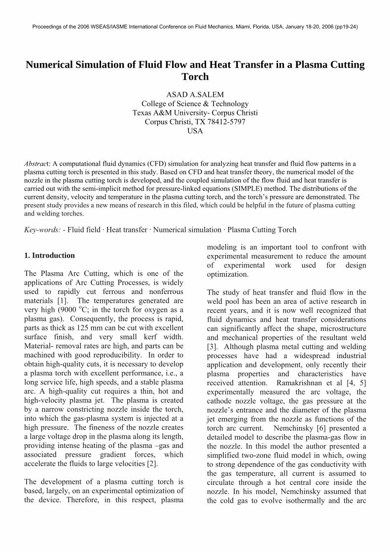
Figure 3: Velocity vectors shown by velocity magnitude (m/s) without JxB.
0=•∇ U
JxBUPU +∇+−∇=∇•∇ 2µ
)(1 JJk
TkTCpUE
T •+∇•∇=∇•ρ
φ∇= EkJ
Proceedings of the 2006 WSEAS/IASME International Conference on Fluid Mechanics, Miami, Florida, USA, January 18-20, 2006 (pp19-24)

As shown in figure 3 the maximum velocity in the plasma cutting torch is near the mid point of the axis of symmetry, and is about 83 m/s. It, also, can be seen from figure 3, that in the region directly under the cathode, the fluid flows downward along the axis of symmetry. Then the fluid is deflected and flow radially outward. No flow re-circulation region is present.
Figure 4: Contours of Static Pressure (Pa) without (JxB).
Figure 5: Contours of Static Temperature (k) without (JxB).
Figure 6: Contours of Electric Potential without (JxB). Figure 4 shows the contours of static pressure distribution in the plasma torch without the effect of (JxB) force. While, Figure 8 shows the static pressure distribution in the presence of the (JxB) force. It can be seen that the presence of the (JxB) force has a significant effect on the pressure distributions in the plasma cutting torch. Figures 5 and 6 show the contours of the temperature and Electric potential without the effect of (JxB) force. Comparing figures 5 and 6 with figures 9 and 10, it is very noticeable that the (JxB) force has very little to negligible influence into the temperature and electric potential distribution in the plasma cutting torch. The computed velocity distribution in the plasma cutting torch with uniform self induced magnetic field is shown in figure 7. As shown, in the region directly under the lower end of the electrode tip, the fluid flows downward along the axis of symmetry. Due to stagnation effect at the anode the fluid is then deflected and flows radially outward. The maximum velocity in the arc plasma is near the mid point of the axis of symmetry, and is about 106 m/s. Beyond this region, i.e. in the region of the arc plasma under the conical surface of the electrode tip, the fluid first flows inward and downward and then, as it approaches the anode, it turns radially outward, again due to the stagnation effect. As a result of the impingement of the high velocity of the heavy plasma particles, the anode surface is subjected to
Proceedings of the 2006 WSEAS/IASME International Conference on Fluid Mechanics, Miami, Florida, USA, January 18-20, 2006 (pp19-24)
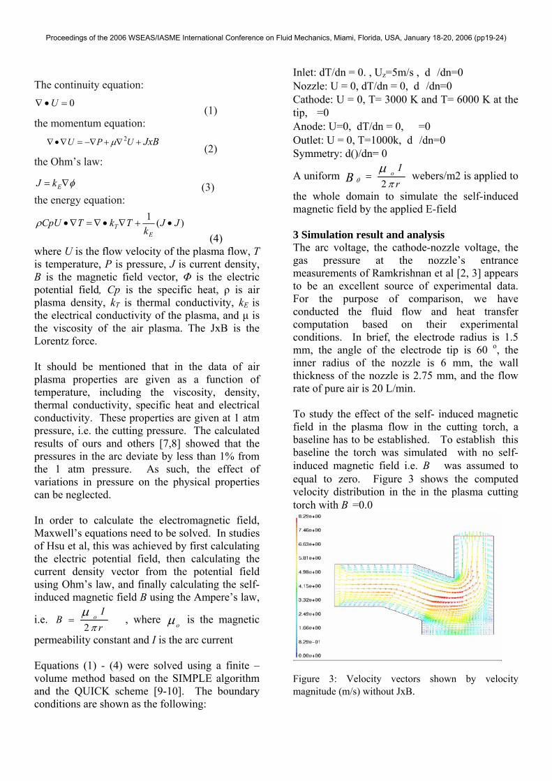
the arc pressure. The computed maximum arc pressure, which is located at the axis of symmetry at the anode surfaces, is about 450 Pa. This compares well with the measured value of about 510 Pa. The presence of the (JxB) force, at in the present case, has a pronounced effect on the velocity distribution in the plasma torch. The fluid flow near the centerline and the outlet of nozzle tend to flow in a counterclockwise circular motion which increases the torch pressure as well as the temperature in that region.
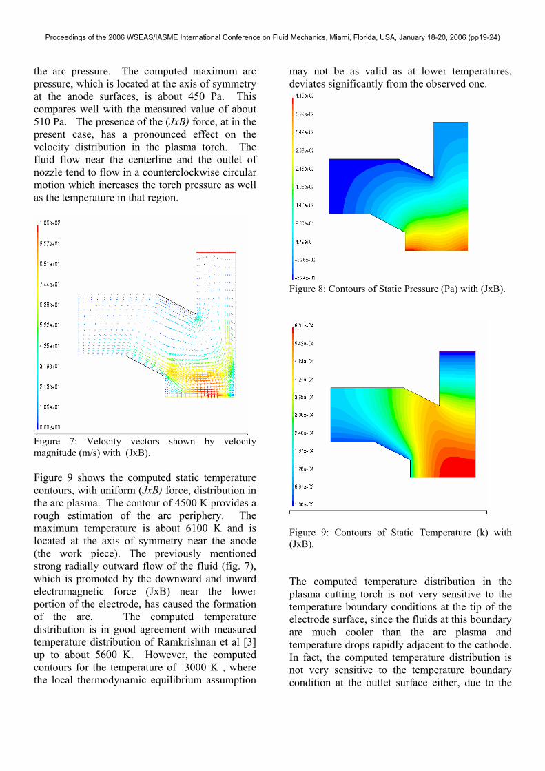
Figure 7: Velocity vectors shown by velocity magnitude (m/s) with (JxB). Figure 9 shows the computed static temperature contours, with uniform (JxB) force, distribution in the arc plasma. The contour of 4500 K provides a rough estimation of the arc periphery. The maximum temperature is about 6100 K and is located at the axis of symmetry near the anode (the work piece). The previously mentioned strong radially outward flow of the fluid (fig. 7), which is promoted by the downward and inward electromagnetic force (JxB) near the lower portion of the electrode, has caused the formation of the arc. The computed temperature distribution is in good agreement with measured temperature distribution of Ramkrishnan et al [3] up to about 5600 K. However, the computed contours for the temperature of 3000 K , where the local thermodynamic equilibrium assumption
may not be as valid as at lower temperatures, deviates significantly from the observed one.
Figure 8: Contours of Static Pressure (Pa) with (JxB).
Figure 9: Contours of Static Temperature (k) with (JxB). The computed temperature distribution in the plasma cutting torch is not very sensitive to the temperature boundary conditions at the tip of the electrode surface, since the fluids at this boundary are much cooler than the arc plasma and temperature drops rapidly adjacent to the cathode. In fact, the computed temperature distribution is not very sensitive to the temperature boundary condition at the outlet surface either, due to the
Proceedings of the 2006 WSEAS/IASME International Conference on Fluid Mechanics, Miami, Florida, USA, January 18-20, 2006 (pp19-24)
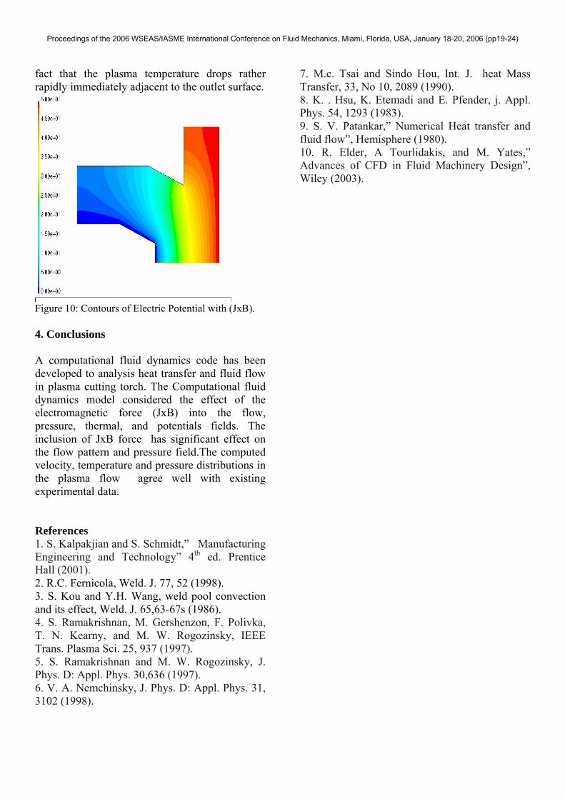
fact that the plasma temperature drops rather rapidly immediately adjacent to the outlet surface.
Figure 10: Contours of Electric Potential with (JxB). 4. Conclusions A computational fluid dynamics code has been developed to analysis heat transfer and fluid flow in plasma cutting torch. The Computational fluid dynamics model considered the effect of the electromagnetic force (JxB) into the flow, pressure, thermal, and potentials fields. The inclusion of JxB force has significant effect on the flow pattern and pressure field.The computed velocity, temperature and pressure distributions in the plasma flow agree well with existing experimental data. References 1. S. Kalpakjian and S. Schmidt,” Manufacturing Engineering and Technology” 4th ed. Prentice Hall (2001). 2. R.C. Fernicola, Weld. J. 77, 52 (1998). 3. S. Kou and Y.H. Wang, weld pool convection and its effect, Weld. J. 65,63-67s (1986). 4. S. Ramakrishnan, M. Gershenzon, F. Polivka, T. N. Kearny, and M. W. Rogozinsky, IEEE Trans. Plasma Sci. 25, 937 (1997). 5. S. Ramakrishnan and M. W. Rogozinsky, J. Phys. D: Appl. Phys. 30,636 (1997). 6. V. A. Nemchinsky, J. Phys. D: Appl. Phys. 31, 3102 (1998).
7. M.c. Tsai and Sindo Hou, Int. J. heat Mass Transfer, 33, No 10, 2089 (1990). 8. K. . Hsu, K. Etemadi and E. Pfender, j. Appl. Phys. 54, 1293 (1983). 9. S. V. Patankar,” Numerical Heat transfer and fluid flow”, Hemisphere (1980). 10. R. Elder, A Tourlidakis, and M. Yates,” Advances of CFD in Fluid Machinery Design”, Wiley (2003).
Proceedings of the 2006 WSEAS/IASME International Conference on Fluid Mechanics, Miami, Florida, USA, January 18-20, 2006 (pp19-24)