
Northstar HORIZON Computer System Manual - Harte Technologies
56
HORIZON ® Computer System Manual (Double Density) 25011C
Transcript of Northstar HORIZON Computer System Manual - Harte Technologies

HORIZON® Computer System Manual (Double Density)
25011C

North Star 2 HORIZON Computer System

North Star Computers, Inc. 14440 Catalina St., San Leandro, CA 94577 USA (415) 357-8500 TWX/Telex (910) 366-7001
HORIZON® Computer System Manual (Double Density)
HORIZON® is a registered trademark of North Star Computers, Inc.
Z80A® is a registered trademark of Zilog, Inc. Copyright© 1978, 1979, 1980, by North Star Computers, Inc.
All rights reserved.

North Star 2 HORIZON Computer System
This manual was digitally remastered by Howard M. Harte, June 2003.
http://www.hartetec.com
If you find any errors, please email [email protected].

North Star 3 HORIZON Computer System
INTRODUCTION
The North Star Computers' HORIZON® is a high-performance, Z80A® based microcomputer system, which is especially suited for business, education, and software development applications. It features fast-access disk storage as an integral part of the package, 4 MHz microprocessor operation, and built-in I/O capability. The HORIZON uses the S-100 bus structure, allowing a large selection of compatible products. The system will support up to 4 disk drives, allowing up to 716K bytes of on-line disk storage. Powerful system software, including North Star Disk BASIC, Disk Operating System, and Monitor program, are provided on diskette with disk versions of the HORIZON. The HORIZON is compatible with nearly all programs previously written for 8080 or Z80 based machines. North Star BASIC programs which run on the North Star MICRO-DISK SYSTEM will also run on the HORIZON. A list of the growing number of HORIZON-compatible applications programs is included in the North Star Newsletter, which you will receive after filling out and returning your Warranty Card. Be sure to read the "Using the Serial Interfaces" section for instructions on connecting a terminal. It is important for every HORIZON user to be familiar with the "Operation and Maintenance" section, and all sections of this manual, and the accompanying manuals, describing the North Star software. There is a lot of material presented here, but you will obtain far more performance from your computer if you take the time to read about all of its capabilities. The HORIZON documentaion includes:
HORIZON Computer System Manual North Star Z80A Processor Board Manual North Star 32K RAM Board Manual North Star System Software Manual

North Star 4 HORIZON Computer System
North Star 5 HORIZON Computer System
TABLE OF CONTENTS Introduction 3 GENERAL INFORMATION Warranty. . . . . . . . . . . . . . . . . . . . . . . 7Cautions . . . . . . . . . . . . . . . . . . . . . . 8Software License. . . . . . . . . . . . . . . . . . . 8 OPERATION AND MAINTENANCE Operation . . . . . . . . . . . . . . . . . . . . . . 9Diskettes . . . . . . . . . . . . . . . . . . . . . . 10Maintenance . . . . . . . . . . . . . . . . . . . . . 10Troubleshooting . . . . . . . . . . . . . . . . . . . 10Out of Warranty . . . . . . . . . . . . . . . . . . . 10 DETAILED INFORMATION Disk Controller Checkout. . . . . . . . . . . . . . . 11Integrated System Checkout. . . . . . . . . . . . . . 15Disk Controller Theory of Operation . . . . . . . . . 19Disk Controller Configuration Options . . . . . . . . 27Disk Drive Configuration. . . . . . . . . . . . . . . 29Motherboard Theory of Operation . . . . . . . . . . . 31Using the Serial I/O Interfaces . . . . . . . . . . . 37Using the Parallel I/O Interface. . . . . . . . . . . 41Using the Real-Time Clock . . . . . . . . . . . . . . 47Motherboard Interrupts. . . . . . . . . . . . . . . . 47HORIZON Grounding . . . . . . . . . . . . . . . . . . 48 APPENDICES Appendix A Bills of Materials. . . . . . . . . . . . A-1Appendix B Pulse Signal Detection. . . . . . . . . . B-1Appendix C Disk Controller Schematic Drawing . . . . C-1Appendix D Motherboard Schematic Drawing . . . . . . D-1

North Star 6 HORIZON Computer System

North Star 7 HORIZON Computer System
WARRANTY
North Star Computers, Inc., warrants the electrical and mechanical parts and workmanship of this product to be free of defects for a period of 90 days from the date of purchase. If such defects occur, North Star Computers, Inc., will repair the defect at no cost to the purchaser. This warranty does not extend to defects resulting from improper use or assembly by purchaser, nor does it cover transportation to the factory. Also, the warranty is invalid if all instructions included in the accompanying documentation are not carefully followed. Any adjustment, modification, or disassembly of any disk drive unit will void the warranty on that disk drive unit. Should a unit returned for warranty repair be deemed by North Star Computers, Inc., to be defective due to purchaser's action, then a repair charge (not to exceed $50 without purchaser's consent) will be assessed. ANY UNIT(S) OR PART(S) RETURNED FOR WARRANTY REPAIR MUST BE ACCOMPANIED BY A DATED COPY OF THE ORIGINAL SALES RECEIPT. The item should be returned to the dealer from whom the product was purchased, for implementation of the warranty. When sending the item to the factory for repair, the dealer must call the North Star Technical Hotline to receive a Return Material Authorization (RMA) number to accompany the item to the factory. Terminals and printers are covered under separate warranties. The following warranty limitation applies to units located outside the United States of America: All costs and arrangements for transportation of the product to and from the factory are borne entirely by the customer. No warranty, expressed or implied, is extended concerning completeness, correctness, or suitability of the North Star equipment for any particular application. There are no warranties which extend beyond those expressly stated herein. This limited warranty is made in lieu of all other warranties, expressed or implied, and is limited to repair or replacement of the product.

North Star 8 HORIZON Computer System
CAUTIONS
1. Correct this document from the addenda sheets, if any, before doing anything else.
2. DO NOT insert or remove any boards from the computer when the
power is on. Note that the power is not off until the front panel power LED has completely dimmed.
3. DO NOT insert or remove IC's from any board while the power is
turned on. Note that the power is not off until the fron panel power LED has completely dimmed.
4. DO NOT connect or disconnect, mount or dismount, or any way
physically tamper with the disk drive(s) or any PC board while the power is turned on.
5. To avoid the possibility of a severe shock, DO NOT touch the
power supply section of the computer whenever the power cord is plugged into an AC outlet.
SOFTWARE LICENSE
The North Star BASIC, DOS and Monitor are copyrighted products of North Star Computers, Inc., and are included with the HORIZON computer under the following license agreement:
The software may be used in conjunction with the North Star HORIZON computer and North Star MICRO-DISK SYSTEM only. The customer may make copies of the software for convenience of use, as long as the North Star copyright notice is preserved with each copy. This license specifically prohibits use of the software in a computer which does NOT include a North Star disk controller board, and also specifically prohibits modification of the software for use in any system which does NOT contain a North Star disk controller board.

North Star 9 HORIZON Computer System
OPERATION AND MAINTENANCE OF THE HORIZON
OPERATION When first beginning a session with the HORIZON computer, check each of the following: A. Be sure the computer and terminal are plugged into the AC
outlet and are known to have been left in a condition ready for use.
B. Check that the terminal cable is properly connected to the
terminal and to the HORIZON standard serial interface connector on the back panel. See the HORIZON Grounding section to be sure the terminal is grounded correctly.
C. Check that the HORIZON and terminal are configured for the same
baud rate and RS-232 or current-loop operation. The terminal must be in full-duplex operation mode. DOS, BASIC, and the Monitor use upper-case ASCII characters.
Select a diskette containing a version of the North Star DOS personalized for your I/O configuration (the standard HORIZON diskette is configured for use with the standard serial I/O interface). The DOS must be the first file on the diskette, starting at disk address 4. Insert the diskette into drive #1 (the left hand drive mounted to the front panel in a two drive system). Orient the diskette so that the write protect notch is up and the label faces to the right. Make sure the diskette is resting gently against the back stop, and then close the drive latch. If power is not already on (check the power LED on the front panel), then turn on the power switch. Otherwise, toggle the reset switch. Both switches are located on the back panel near the fan. Disk drive #1 should turn on momentarily, and the terminal should print a plus sign (+) to indicate that the DOS is loaded and awaiting a command. Any DOS command may now be typed (e.g. GO BASIC). Refer to the North Star System Software Manual for complete details of the use of the North Star software.

North Star 10 HORIZON Computer System
DISKETTES During the course of a lengthy session with the HORIZON, if additions or modifications are made to any program or data file, it is recommended that the user periodically make a "back-up" copy of the file, either on a loaded diskette or, preferably, on an extra diskette. This precaution will minimize the inconvenience caused by an inadvertent user error, power failure, or computer failure. Keep a piece of masking tape over the write protect notch on each diskette as much as possible to protect against the information being accidentally destroyed. The write-protect tape should NEVER be removed from your original HORIZON diskette. All diskettes should contain a label describing the diskette contents and relevant version numbers and dates. When not inserted in the computer, diskettes should be filed in the protective envelopes in a dust-free location away from excessive heat and magnetic fields where accidental physical damage cannot occur. Avoid any contact with the diskette media through the holes in the diskette case. MAINTENANCE
Periodically, use the North Star Monitor program to test all the RAM memory in the computer, and use the DOS disk test utility to test each drive. Refer to the "Getting Started" section of the North Star System Software Manual for complete details of how to perform these test procedures. To keep your computer looking attractive, care for it as you would a piece of furniture; wipe fingerprints and dirt from the front panel, and occasionally polish the cover. TROUBLESHOOTING Should your computer system become non-operational, the first step is to isolate the problem. If you have determined that the problem is with the HORIZON computer (and not, for example, with the terminal, a bad diskette, or with a change in software), then, if possible, run your boards in another S-100 computer, one at a time, to isolate the bad board. If this is not possible, follow the checkout procedure in the assembly manuals for each component of your system. OUT OF WARRANTY REPAIR If your unit is out of warranty and you are unsuccessful at diagnosing or repairing the problem, out-of-warranty service may be arranged with a local dealer or other experienced local computer technician. Contact your local dealer for information.

North Star 11 HORIZON Computer System
DISK CONTROLLER CHECKOUT
The following terms are used in specifying expected test results:
GND ground, 0 volts DC LOW logic zero, 0-.7 volts, normally about .3 volts HIGH logic one, 2.4-5.0 volts, normally about 3 volts +5V +5 volts from power supply AC Signal with pulses (as opposed to DC signal)
When referring to the name of a signal from the schematic drawings, if the signal is identified with a bar over its name, then the name is followed by a slash (e.g., STORE/) in the checkout instructions. When describing an AC pulse, the notation (±W,P) refers to a positive or negative pulse with a width of W appearing with a period of P. For example, a positive pulse with width 120 nanoseconds appearing every 25 microseconds would be described as (+120ns,25us). When using an oscilloscope to test the board, a "scope ground" may be installed by soldering a "bridge" of jumper wire between the two PC board holes that connect edge connector pins 50 and 100 near location 12D. Note that either of the two regulator machine screws can be used for ground test points. G1. With the computer power off, install only the disk controller
board into the motherboard. The ribbon cable should not be plugged into the board. Turn on the computer power and check for the following counter timing signals.
SIGNAL LOCATION DESCRIPTION LCLK/ 15B pin 12 AC, 500ns square wave CC3 6A pin 11 AC, 8us square wave CC6 7A pin 11 AC, 128us square wave (some jitter) CC11 8A pin 11 AC, 2ms square wave (some jitter) CC15 9A pin 11 AC, 32ms square wave (some jitter) SC03 15C pin 6 AC, 500ms square wave (no-name) 3D pin 6 AC, 8.3sec square wave AUTO-OFF 6C pin 11 AC, (+8.3sec,33sec)
If the signals are not as listed, then refer to the schematic drawings and trace backwards to locate and correct the problem.
G2. This step will check the write circuitry while simulating writing a continuous stream of "one" data bits in single-density format during each sector.

North Star 12 HORIZON Computer System
A. With the computer power off, remove the disk controller board from the motherboard.
B. Remove the 74LS74 IC from location 14C, bend up pin 9 of the IC, and re-insert the IC, so that pin 9 is outside the IC socket and does not make contact with IC socket pin 9.
C. Connect a clip lead between cable connector (J2) pin 22 and pin 30. If you do not have a clip lead, then tack solder a wire on the solder side of the board between 13B, pin 11, and 14B, pin 13.
D. With the computer power off, install only the disk controller board and the processor board into the motherboard, and turn the computer power on.
E. Check the following signals while the computer reset switch is depressed (hold depressed with a rubber band):
SIGNAL LOCATION DESCRIPTION
WR-SHIFT/ 6D pin 6 AC, (-lus,8us) LD-WSR/ 6D pin 15 AC, (-8us,64us) WS7 6D pin 13 AC, (-96us,32ms) i.e. mostly HIGH WS10 5C pin 15 AC, (-96us,32ms) i.e. mostly HIGH WRITE PULSE 3C pin 5 AC, (+approx 600-700ns,4us) (no name) 3C pin 13 AC, (+approx 600-700ns,4us) READ DATA 14B pin 12 AC, (+approx 600-700ns,4us)
If the signals are not as listed, then refer to the schematic drawings and trace backwards to locate and correct the problem.
G3. This step will check the read circuitry while simulating reading a continuous stream of zero data bits in double density format during each sector. If using a scope to check signals, then sync positive on 13C, pin 9. Continue following signals while the computer reset switch is depressed.
SIGNAL LOCATION DESCRIPTION WINDOW 13C pin 9 "Window", HIGH for 96us then LOW
occurs every 34 milliseconds. RE 5B pin 6 "Read Enable", goes HIGH at 480us ACQUIRE 5A pin 5 "Acquire Phase of Incoming Signal",
goes HIGH with RE, duration 100-150us. 2BR 3B, pin 5."Twice Bit Rate", LOW at first, 4us
square wave for 32us when RE goes HIGH, then 2us square wave.

North Star 13 HORIZON Computer System
DDI 4B pin 9 "Double-Density Indicator", goes HIGH at 512us (32us after RE)
HE 14C pin 5 "Hunt Enable", goes HIGH at 736us. OP-AMP-OUTPUT Rt. Side R7 See Note 1. DATA WINDOW 4D pin 5 May begin either HIGH or LOW, then
4us square waves after RE. WIND DATA 4D pin 9 "Separated Data", always LOW, except
narrow pulses at ACQUIRE. RSn
15D pins 3, 4,5,6,10,11 12,13
Read Shift Register", all outputs always LOW.
BODY 5B pin 10 LOW Note 1: Initializes during WINDOW by slewing to +5 volts. During ACQUIRE there will be numerous small positive or negative pulses (phase corrections). A DC shift of less than 1/4 volt may be seen at this time if a frequency adjustment occurs. The resultant DC level should remain until the next WINDOW pulse. Note 2: The two op-amp (LF356) inputs are very high impedance and attempts to observe them with a scope probe can affect the circuit.
A. Remove the 74LS74 IC at location 4D, lift pin 9 of the IC, and re-insert the IC so that pin 9 is not inserted in the IC socket. Then, with the computer reset switch depressed, check of the following signals:
SIGNAL LOCATION DESCRIPTION BODY 5B pin 10 Goes HIGH at 780us SYNC BLANK 1B pin 13 Pulse beginning at 780us,
duration 38-50us. B. Re-insert the pins of the IC's at locations 14C and 4D into
their IC sockets and remove the clip lead or soldered wire. The disk controller board is now checked-out. If the disk controller is to be used in applications where a special drive motor off time is required, then refer to the Disk Controller Configuration Options section for details. Also, if the disk controller interrupt logic is to be used, then refer to the Disk Controller Theory of Operation and Configuration sections for details.

North Star 14 HORIZON Computer System

North Star 15 HORIZON Computer System
INTEGRATED SYSTEM CHECKOUT
This section describes a step-by-step process for integrating the major components of your system in a way designed to localize any problems.
I1. Refer to the instructions for your processor board and configure the auto-jump address to be the disk controller bootstrap PROM starting address (E800H).
12. Be sure the HORIZON power is off, and then plug the processor board into its motherboard connector (normally P1) and plug the disk controller board into its motherboard connector (normally P9). No other board should be plugged into the motherboard at this time, and no diskette should be inserted in the disk drive(s). Connect the disk drive ribbon cable as shown in 2C. Be sure the two PC boards are properly seated in their edge connectors, and then turn on the power. The disk drive motor(s) should turn on and the red light on drive #1 should turn on. Then the motor(s) should turn off after twelve seconds. If the motor(s) do start, then proceed to step 13. Otherwise, if the motor(s) do not turn on, continue this step as follows:
A. Depress and release the reset switch. If the motor(s) still do not turn on, then proceed to part B. If the motor(s) now turn on, then check the power sequencing circuitry on the motherboard and the processor board. Proceed to step 13, after locating and correcting the problem.
B. Momentarily ground 12B, pin 3, on the disk controller board by briefly shorting it to 12B, pin 7, with a piece of jumper wire. If this causes the motor(s) to turn on, then remove the wire and proceed to part C. If this does not cause the motor(s) to turn on, then check the signal cable connections to the disk drive and the power cable connections to the disk drive. After locating and correcting the problem, start over at the beginning of step 12.
C. Momentarily ground 13C, pin 1, (MOTOR SET/) by briefly shorting it to 13C, pin 8, with a piece of jumper wire. The motor(s) should turn on and then stay on for about 12 seconds after the wire is removed. If this succeeds, then proceed to part D. If this does not succeed, then the problem is with the counting circuitry on the disk controller board. After locating and correcting the problem, start over at step 12.

North Star 16 HORIZON Computer System
D. Turn off the power and remove the 74LS00 from location 7C.
Remove the 74LS08 from location 6C, bend pin 3 of the IC out and re-install the IC into the IC socket, so that pin 3 if the IC does not make contact with pin 3 of the IC socket. Turn on the computer power and ground motherboard pin 43 by shorting it to motherboard pin 50 with a piece of jumper wire. This experiment will force the processor to sequentially read every address in the computer continuously, including the memory-mapped I/O locations that turn on the drive motor(s) and select the drive(s). If the motor(s) do not turn on, then trace backwards from the signal MOTOR-SET/ to find out why. After correcting the problem, remove the jumper, replace the IC's correctly at locations 7C and 6C, and start over at the beginning of step 12. If the motor(s) do come on, that indicates that the problem detected at the beginning of this step is probably a result of the PROM program not being correctly executed. Remove the jumper, replace the IC's, and proceed to part E.
E. Turn off the power and ground PRDY on the disk controller
board by shorting 11A, pin 7, to 11A, pin 8. Turn on the power. The processor should pause immediately after performing the auto-jump sequence just before executing the first instruction of the disk controller PROM. The S-100 address bus A0-A15 (see the ZPB Manual, Appendix B for bus pin numbers) should contain E800H. (If this is not so, then the problem is with the auto-jump circuitry on the processor board.) The S-100 data input bus DI0-DI7 (see the ZPB Manual Appendix B for pin numbers) should contain 0EH which is the first instruction byte in the PROM. If this is not so, then the problem is with the PROM circuitry on the disk controller board. Trace backwards through this logic to isolate the problem. After correcting the problem, remove the jumper and start over at the beginning of step 12.
13. Next, power up the HORIZON with no diskette in drive #1 again.
Approximately 12 seconds after the drive is selected and the heads load, the motor(s) will turn off. The processor at this point should be executing a tight JMP loop, indicating a read error. This can be checked by observing a continuous stream of pulses on the disk controller board at 7C, pin 6, (DI-GATE/).
14. Connect a serial I/O terminal to the standard serial interface
connector on the back panel. (See the Using the Serial Interfaces section for a discussion of serial interface

North Star 17 HORIZON Computer System
cabling.) Be sure the terminal is grounded correctly as described in the HORIZON Grounding section. The terminal should be set for full-duplex operation and the baud rate must match that of the standard serial interface.
15. With the computer power off, plug the RAM board(s) into any
free connectors in the motherboard. 16. Turn on the computer power, and insert the personalized
HORIZON diskette into drive #1, referring to the GETTING STARTED section of the North Star System Software Manual for correct diskette handling procedures. Close the drive door and toggle the reset switch. One of three results will occur:
A. The bootstrap program goes into the error loop as
described in step 13. This indicates trouble reading the data from the diskette, which can mean a bad diskette, a faulty disk drive, or faulty read circuitry on the disk controller. Return to the disk controller checkout instructions in this case.
B. The bootstrap program loads the DOS, but communication
with the terminal is not established. If the DOS gets as far as the terminal I/O input routine, then pulses will be seen on pin 46 (SINP) of the bus every three instructions. If you detect these pulses, then the problem is with the terminal or the serial I/O interface circuitry. Otherwise, if these pulses are not observed, then the situation is more complicated, and is probably a result of an error in the RAM memory.
C. The bootstrap program successfully loads the DOS and it is
possible to enter commands from your terminal.
Congratulations! Your HORIZON is now operational. It is ready to communicate with a terminal. The next step is to use the North Star software to more fully check out your HORIZON. Refer to the GETTING STARTED section of the North Star System Software Manual for more complete details.

North Star 18 HORIZON Computer System
North Star 19 HORIZON Computer System
DISK CONTROLLER THEORY OF OPERATION
The North Star double density disk controller is an integrated combination of hardware and software. It is designed specifically to provide a complete, compact and economical disk drive controller for use with S-100 bus 8080 or Z80 microcomputer systems. DISK CONTROLLER HARDWARE The disk controller is implemented from medium and small scale TTL integrated circuits and PROM memory. The entire controller fits on a single 5"x10" printed circuit card. The block diagram below shows the general organization of the disk controller. 1. Address Buffers and Select Logic: The sixteen address lines are
received with Schmitt trigger buffers (7D, 10D, 11D) to provide noise immunity. The high order 8 address lines are used by the board select PROM (DSEL, 11C) to determine if the current memory reference is addressing the controller board. The low order eight address lines are used to present data and control information to the controller. The use of these bits is determined by the outputs of the board select PROM.
2. Write Data Logic: If the controller is issued a write data byte command, then the low order eight address bits are interpreted as data to write and are gated into the write shift register (6D). The controller will place the CPU in a wait- state until the shift register is empty and only then clock the new data into the shift register. Write encoding (using the FM encoding method for single density and MFM encoding for double density) and write precompensation are controlled by the logic at locations 3C, 4C, and part of 5C.
3. Read Data Logic: Raw data from the disk is standardized by the RD-DAT-OS one-shot (5A). A phase-locked loop (lA, 4A, and parts of 1B, 5A) tracks the trailing edge of RD-DAT-OS to match the frequency of the incoming data. The phase-locked loop output drives the data separator (3B, 4D), whose outputs, DATA-WINDOW (clock) and WIND-DATA (data), go to the 8-bit read data shift register (15D). The read shift register ouputs are multiplexed with the status bits (12D, 13D, 14D) and driven onto the Data Input Bus (10D, 11D). When reading, if double density data is encountered, the double density indicator (DDI, 4B) is set.

North Star 20 HORIZON Computer System
Figure 1T. Disk Controller Block Diagram

North Star 21 HORIZON Computer System
4. On Board PROM: Bootstrap software (8080/Z80 machine code) is
stored in an on-board 256 byte bipolar PROM (DPGM, 9D). This PROM provides 256 bytes of memory. The 8 low order address bits address the PROM's. The PROM outputs are driven onto the Data Input Bus.
5. Clock Circuit: The crystal clock oscillator circuit (15B)
provides 2 MHz clock signals to synchronize the control circuitry.
6. Read, Write Control: A read or write command sequence begins
with detection of a sector pulse. A read or write command must be issued to the controller within a 96 microsecond window after the sector pulse. Writing data begins a the end of the window. The controller writes one byte of zeros. Writing stops at the next sector pulse. Reading starts some time after the end of the window so as to be in the middle of the written preamble. First the phase-locked loop is turned on by the read enable (RE) signal. After locking to the incoming data is achieved, the hunt enable (HE) signal causes the search for a sync character to begin. When a sync character is detected, the controller enters "body" mode. When the software issues a read command to the controller, the controller will put the CPU into the wait state until the read shift register is full.
7. Command Decode Logic: When a command address is issued to the
controller, the 8 low order address bits are decode to deter-mine which command actions are to be taken and which disk con-trols should be performed. See the Disk Controller Commands section for details.
8. Counters: The counters (6A, 7A, 8A, 9A) provide sector timing
and read and write command sequencing. The counter (15C) is the sector position counter. The output of 9A provides pseudo sector pulses in case no diskette is inserted in the drive or the drive motor is off, and also allows discrimination between sector holes and the index hole. The counter (3D) is used to count disk revolutions to determine when to cause automatic motor off. The counters (9B) are used to count bits while read-ing or writing data.

North Star 22 HORIZON Computer System
DISK CONTROLLER COMMANDS Commands to the disk controller are specified by memory read references to addresses within a particular 1K byte block of the CPU address space. The 1K byte block subdivides into four cases. In all cases the high order 6 address bits (BS) are used to determine if the 1K block is addressed (i.e. the controller board is selected). The next two bits determine the subcase and the use of the low order eight bits depends on the subcase. CASE 0 PROM Addressing (e.g., E8xx)
. . . . . . . . . . . . . . . . . | BS | 0 | PROM Address | . . . . . . . . . . . . . . . . .
Read byte from the 256 bytes of PROM.
CASE 1 Write byte of data (e.g., E9xx) . . . . . . . . . . . . . . . . . | BS | 1 | DATA | . . . . . . . . . . . . . . . . .
Write a byte of data to the disk. Wait if the write shift register is not empty. The low order 8 bits specify the byte to be written.
CASE 2 Controller Orders (e.g., EAxx) . . . . . . . . . . . . . . . . . | BS | 2 |DD|SS|DP|ST| DS | . . . . . . . . . . . . . . . . .
Load 8-bit order register from low order 8 address bits.
DD controls density on write DD=1 for double density and DD=0 for single density.
SS specifies the side of a double-sided diskette. The
bottom side (and only side of a single-sided diskette) is selected when SS=0. The second (top) side is selected when SS=1.

North Star 23 HORIZON Computer System
DP has shared use. During stepping operations, DP=O
specifies a step out and DP=1 specifies a step in. During write operations, write precompensation is invoked if, and only if, DP=1.
ST controls the level of the head step signal to the disk
drives. DS is the drive select field, encoded as follows:
0 = no drive selected 1 = drive 1 selected2 = drive 2 selected4 = drive 3 selected8 = drive 4 selected
CASE 3 Controller Commands (e.g., EBxx)
. . . . . . . . . . . . . . . . . | BS | 3 | DM | CC | . . . . . . . . . . . . . . . . .
Perform a disk controller command. The commands are specified by the 8 low order address bits. DM The DM field controls what gets multiplexed onto the
DI bus during the command.
1 = A-status 2 = B-status 3 = C-status 4 = Read data (may enter wait state)
CC Command code.
0 = No operation 1 = Reset sector flag 2 = Disarm interrupt 3 = Arm interrupt 4 = Set body (diagnostic) 5 = Turn on drive motors 6 = Begin write 7 = Reset controller, de-select drives, stop motors

North Star 24 HORIZON Computer System
DISK CONTROLLER STATUS BYTES There are three status bytes that can be read on the Data Input Bus.
A-Status . . . . . . . . . | SP | IX | DD | MO | WI | RE | SP | BD | . . . . . . . . .
B-Status . . . . . . . . . | SF | IX | DD | MO | WR | SP | WP | TO | . . . . . . . . .
C-Status . . . . . . . . . | SP | IX | DD | MO | SC | . . . . . . . . .
SF Sector Flag: Set when sector hole detected, reset by
software. IX Index Detect: True if index hole detected during previous
sector. DD Double Density Indicator: True if data being read is encoded
in double density. MO Motor On: True while motor(s) are on. WI Window: True during 96-microsecond window at beginning of
sector. RE Read Enable: True while phase-locked loop is enabled. BD Body: Set when sync character is detected. WR Write: True during valid write operation. SP Spare: Reserved for future use. WP Write Protect: True while the diskette installed in the
selected drive is write protected. SC Sector Counter: Indicates the current sector position. T0 Track 0: True if selected drive is at track zero.

North Star 25 HORIZON Computer System
DISK CONTROLLER DATA FORMAT
Each diskette has 35 (70 for quad-capacity) tracks of data. Each track is divided into 10 sectors. The rotational position of the beginning of the sectors is marked by sector holes in the diskette. Each sector is recorded using the following format. This information is recorded starting about 96 microseconds after the sector hole is detected.
SINGLE DENSITY DOUBLE DENSITYZeros 16 Bytes 32 bytes Sync Char (FB) 1 Byte 2 bytes Data 256 Bytes 512 bytes Check Char ___1 Byte ___1 byte 274 bytes 547 bytes
The check character is computed iteratively by setting it to zero and then exclusive ORing each successive data byte value with the current value of the check character and left cycling the result.
DISK CONTROLLER SOFTWARE
The basic low-level function of the controller is to transfer or verify 256/512 byte sectors of data between a specified area on the disk and a specified area of the RAM. The algorithm now described accomplishes this task. The program to perform this algorithm resides in the DOS. 1. Start the drive motor(s) if they were off and wait for the
motor to get up to speed.
2. If the disk drive to be selected is different than the drive currently selected or if the motor(s) were off, then select the new drive, and wait for the index detect signal to be true.
3. If the disk read/write heads are not already at the desired track, then the heads must be stepped in or out to the correct track. First, set the step direction flip-flop and determine the number of tracks to step. Each step is accomplished by the following sequence:
A. Set the step flip-flop, B. Reset the step flip-flop, C. Wait the specified track stepping time.
4. Wait until the next sector pulse and test if the disk is at the desired sector position by reading C-status. If not, then repeat this step.

North Star 26 HORIZON Computer System
5. If the DATA WRITE case, then:
A. issue begin write command. B. wait for WI status bit to be false. C. write 15/31 bytes of zeros. D. write the sync character(s) (FB hex). E. write 256/512 bytes of data from RAM while computing
the cyclic check character. F. write the check character. G. if more blocks to write on the same track, then wait until
the next sector pulse and repeat from Step A, otherwise done.
6. If READ case, then:
A. wait for RE to be true and test DD status bit. B. wait for sync character detection (i.e. body mode). Report
an error if the sync character is not detected. C. read 256/512 data bytes into RAM while computing the check
character. D. read the check character and compare with the computed
check character. Report an error if they are not equal. E. if there are more blocks to read on the same track, then
wait until the next sector pulse and repeat from Step A, otherwise done.
7. If VERIFY case, then all is the same as the READ case, except
that in Step C, data bytes read from the disk should be com-pared for equality with the data in RAM. Report an error if corresponding bytes do not compare.
DISK CONTROLLER INTERRUPTS The software provided with the disk system is not interrupt driven. The controller can cause an interrupt on any one of the interrupt lines on the S-100 bus by connecting the appropriate jumper at the lower left corner of the controller board. An interrupt will be generated at every sector pulse while the interrupt is armed in the controller. See the COMMANDS section for details of interrupt arming and disarming. Special user generated, interrupt driven software can be written, which uses the controller sector pulse interrupt. Before the low level controller software is called, interrupts should be disabled. If an interrupt occurs during data transmission, then data can be lost as a result of excessive delay in the interrupt routine.

North Star 27 HORIZON Computer System
DISK CONTROLLER CONFIGURATION OPTIONS
There are a number of configuration options possible on the disk controller board that are specified by wiring jumpers on the board. The desired configuration should be wired according to the following instructions before the board is used:
J1. Signal grounding
The "G" jumper, below location 5D, is normally installed when the disk controller is used in a HORIZON. If the disk controller is to be used in another S-100 bus computer, then the "G" jumper should be installed only if motherboard signal 61 is used as ground in that computer.
J2. Automatic motor off time.
Normally, the disk drive motor(s) will turn off 9.6 seconds after the last disk activity. If some other automatic motor off delay time is desired, then cut the traces at location 2D on the solder side of the PC board, which connect "C" to "2" and "D" to "1". Then, connect two jumper wires on the component side of the PC board, at location 2D, according to the following table:
DELAY TIME FIRST JUMPER SECOND JUMPER
3.2 Seconds Connect D to 3 Connect 2 to 1 6.4 Seconds Connect C to 3 Connect 2 to 1 9.6 Seconds Connect C to 2 Connect D to 1 12.8 Seconds Connect B to 3 Connect 2 to 1 16.0 Seconds Connect B to 2 Connect D to 1 19.2 Seconds Connect B to 2 Connect C to 1 25.6 Seconds Connect A to 3 Connect 2 to 1 28.8 Seconds Connect A to 2 Connect D to 1 32.0 Seconds Connect A to 2 Connect C to 1 38.4 Seconds Connect A to 2 Connect B to 1
J3. Sector Interrupts
The disk controller board includes logic which can cause an interrupt to occur each time a sector hole is detected on a diskette. Normally, this logic is disabled. To use this logic, first cut the two traces on the solder side of the PC board, near locations 10A and 1OB, which connect "J" to "K" and "J" to "E". Second, install two jumper wires on the component side of the PC board, which connect "S" to "J" and "I" to "K". Third, cut the trace below location 4D on the solder side of the PC board that connects "Y" to "PH/". Finally, connect a jumper wire below location 4D on the component side of the PC board, which connects "Y" to the position for the type of interrupt desired (VI0/ to PINT/).

North Star 28 HORIZON Computer System

North Star 29 HORIZON Computer System
DISK DRIVE CONFIGURATION
If the HORIZON is to be configured with only one disk drive connected to the controller then no modification is required for the disk drive. If two or more drives are to be connected to the controller, then the following disk drive modifications must be made. Note, that when there are two disk drives mounted in the HORIZON front panel, drive #1 should be on the left and drive #2 should be on the right. If a third or fourth drive is to be connected, then drive #3 and drive #4 will be mounted outside of the HORIZON chassis.
A. The drive number for each drive must be programmed using the program shunt (located at 1F) on the disk drive PC board. The three metal straps, labeled DS1, DS2, and DS3, specify whether the drive is to be selected as drive 1, 2, or 3, respectively. For each drive, the strap for the desired drive number should remain connected and the other two straps should be dis-connected. Straps can be disconnected by removing the strap assembly from the DIP socket, spreading one of the pins for each undesired strap, and plugging the assembly back in such that the spread pins are not inserted into the DIP socket. Each drive should be programmed with a different drive number. One drive must be number one.
To program a drive as drive number 4, perform he following instructions on the printed circuit board mounted on top of the disk drive:
1. Solder a jumper wire between pin 34 of edge connector Jl and location 1F, pin 6. Take great care to connect the wire to the very tip of pin 34, so that the ribbon cable connector can slip as far onto J1 as possible.
2. Solder a jumper wire between 1F, pin 9, and 1F, pin 11.
3. The unmarked strap location between MX and MH, at location 1F, is now the location for programming drive 4. It can be labeled DS4. This strap should remain connected and the straps labeled DS1, DS2, and DS3 should be disconnected. Be sure to disconnect this strap if the drive is ever programmed to be drive 1, 2 or 3
B. The strap, labeled MX on the program shunt (located at 1F), should be disconnected. Be sure that the LH strap (alternatively labeled HS on some drives) remains connected and the MH strap remains disconnected.
C. Five pull-up resistors for line termination on the ribbon cable are located in the DIP resistor network at position 1E. Only the drive plugged in at the end of the ribbon cable should have this resistor package plugged in. Additional

North Star 30 HORIZON Computer System
drives plugged in along the cable should have the resistor package removed. In a dual-drive system, the resistor package should be in the right hand disk drive (drive #2).
D. when using a doubled-sided drive, make certain that the shunt
at 1E is properly configured. The connection for HS (Head Select) is between Pins 1 and 16. To select drive one (DS1), connect Pin 2 to Pin 15. To select drive two (DS2), connect Pin 3 to Pin 14. To select drive three (DS3), connect Pin 4 to Pin 13. To select drive four (DS4), connect Pin 5 to Pin 12 and to Pin 34 of edge connector Jl; also, cut trace from Pin 6 of the edge connector. Pin 6 and 11 (the MUX shunt), Pins 8 and 9 (the HM shunt), and Pins 7 and 10 should not be connected. For proper pin configurations, see the "DOUBLE-SIDED DRIVE SELECT CONFIGURATION" diagram below.
Only the drive plugged in at the end of the ribbon cable should have the DIP resistor network at location 2F plugged in. Additional drives plugged in along the cable should have the resistor package removed.
DOUBLE-SIDED DRIVE SELECT CONFIGURATION
North Star 31 HORIZON Computer System
MOTHERBOARD THEORY OF OPERATION
MOTHERBOARD HARDWARE 1. Power Regulators
Three-terminal regulators, types 7805, 7812K, 78L12, and 79L12 supply regulated +5V, +12V, +12V and -12V, respectively to the motherboard electronics and the floppy disk drive electronics. Tantalum and disk ceramic bypass capacitors are used to suppress oscillations in the regulator outputs and to filter noise on the power lines.
2. S-100 Bus Interface Octal Bus Drivers/Receivers, at locations 6A and 7A, are used to buffer and drive the S-100 bus Data Output and Data Input buses on the S-100 bus to and from the motherboard internal bi-directional data bus (UO-U7). S-100 bus address lines A3-A7 are matched with the code speci-fied on the port select header (5B) to select the motherboard during Z80 IN and OUT instructions. Address lines A0-A2 are decoded (9D) to select one of the eight motherboard ports. See the Motherboard I/O Port Addressing section for details. Bus Control signals SINP, SOUT, SWO/, and PDBIN are used to direct data flow to and from the internal bus, peripheral interfaces, and the S-100 backplane lines. The power-on-clear (POC) signal is used to reset all logic on the motherboard to a known state when the computer is reset or when power is turned on.
3. Serial Interfaces
The HORIZON motherboard includes two serial I/O interfaces. They both come standard with the HORIZON. They are both identical in capabilities. Each serial interface is based on the 8251 integrated circuit Universal Synchronous/Asynchronous Receiver/Transmitter (USART). The primary function of the USART is to perform serial/parallel conversion of data between the computer and the I/O interface.

North Star 32 HORIZON Computer System
In addition, the USART can perform a wide variety of control functions under program control from the processor. In particular, the USART can perform standard asynchronous and synchronous communication, generating and detecting start bits, stop bits, parity bits, sync bytes, and interface control signals. For details of using the USART, consult an 8251 data sheet. Each serial interface can be configured for RS-232 or current loop operation. TTL to RS-232 level shifting of interface signals is performed by RS-232 drivers 3B and 4B. RS-232 to TTL levels are shifted by RS-232 receivers 3C and 4C. The RS-232 interface signals can be configured onto each 25-pin interface connector, so that each serial interface can communicate with either a modem or a serial terminal with the headers at locations 3D and 4D. For current loop operation, the RS-232 driver chip is replaced by a header containing a current loop driver. Resistors R16, R17, R24, and R25 provide current source and sink capabilities for current loop operation. Provision for synchronous mode communication has been made in the serial interfaces. Baud rate clocks required for synchronous communication can be transmitted with the RS-232 drivers (1B) and received with the RS-232 receiver (1D), by properly configuring the Left Special Clock header (1D) and the Right Special Clock header (2C).
4. Parallel I/O Interface
The 8-bit parallel ports are interfaced to the internal data bus by octal latches, IC type 74LS373, at locations 9A (input) and 8A (output). These are gated to and from the internal bus by signals PI-to-U/ and LD-PO, respectively. Configuration of the Parallel Port Control header at location 9C, allows specification of the conditions which enable the data output latch, load the data input latch, clock the input and output control flip-flops P-O-FLG and P-I-FLG, and drive the SPARE conditions to the parallel interface.
5. Control/Status Byte When enabled by the port decoder, the motherboard status byte is gated onto the internal data bus by the octal buffer at 5A. In addition to flags hardwired on the PC board, there are also two spare status bits which may be defined by the user when Jl and J2 are cut and the lines are wired.

North Star 33 HORIZON Computer System
Various on-board control functions are performed by control decoder chip 9B, a 74LS138 one-of-eight decoder, and the 74LS259 addressable latch at 8B. These functions include arming and disarming the on-board interrupt request conditions, and resetting the various flags.
6. Interrupt Control
Various interrupts can be generated for the on-board serial and parallel I/O interface conditions, as well as the real-time clock. These interrupt request conditions are turned on and off by open collector gates 2A, 2B, and 7B, which furnish signals to the interrupt configuration header at 1A. The user may then route the various interrupt requests to the backplane interrupt lines VIO/-VI7/, PINT/ and NMI/. These lines are pulled low to request an interrupt.
7. Baud Rate Generation and Selection
A total of 9 baud rate clocks from 9600 x 16 to 75 x 16 are generated on the motherboard from the S-100 bus 2 MHz clock. These are divided down to the proper frequencies by four 4-bit counters, types 74LS161 74LS393, at locations 5D, 6D, and 7D. The baud rates generated are available at the Baud Rate Selection header at 2D. The clocks are expressed sixteen times the desired baud rates, since this is what the USART's generally required.
8. Real-Time Clock
The real-time clock feature allows generation of a signal to the processor at regular intervals. The clock intervals are divided down from a tap on the baud rate generator by the MOS 14-bit counter at 1OB, a type 4020 IC. A total of 12 intervals, from 3.328 ms. to 27.263 seconds, are available at the Clock Rate header at 10A. The selected clock is used to set the clock flip-flop (CLK-FLG). The clock flag condition is available to programs as a bit in the motherboard status byte. The clock flag condition can also be jumpered to request an interrupt.
North Star 34 HORIZON Computer System
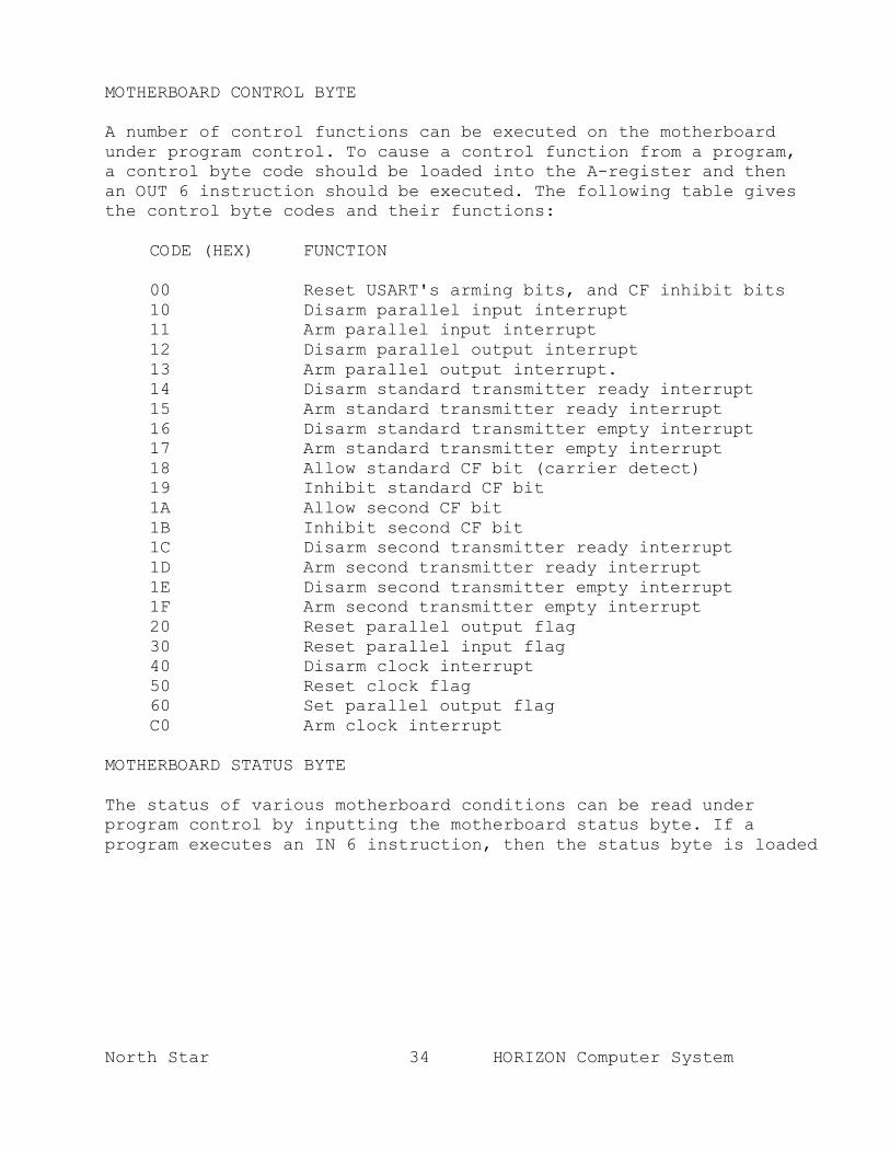
MOTHERBOARD CONTROL BYTE A number of control functions can be executed on the motherboard under program control. To cause a control function from a program, a control byte code should be loaded into the A-register and then an OUT 6 instruction should be executed. The following table gives the control byte codes and their functions:
CODE (HEX) FUNCTION 00 Reset USART's arming bits, and CF inhibit bits 10 Disarm parallel input interrupt 11 Arm parallel input interrupt 12 Disarm parallel output interrupt 13 Arm parallel output interrupt. 14 Disarm standard transmitter ready interrupt 15 Arm standard transmitter ready interrupt 16 Disarm standard transmitter empty interrupt 17 Arm standard transmitter empty interrupt 18 Allow standard CF bit (carrier detect) 19 Inhibit standard CF bit 1A Allow second CF bit 1B Inhibit second CF bit 1C Disarm second transmitter ready interrupt 1D Arm second transmitter ready interrupt 1E Disarm second transmitter empty interrupt 1F Arm second transmitter empty interrupt 20 Reset parallel output flag 30 Reset parallel input flag 40 Disarm clock interrupt 50 Reset clock flag 60 Set parallel output flag C0 Arm clock interrupt
MOTHERBOARD STATUS BYTE
The status of various motherboard conditions can be read under program control by inputting the motherboard status byte. If a program executes an IN 6 instruction, then the status byte is loaded

North Star 35 HORIZON Computer System
into the A-register. The following table shows the meaning of the bits in the status byte. Note, that two of the bits can be jumpered by the user to provide special status conditions:
BIT STATUS CONDITION 7 Parallel output flag 6 Parallel input flag 5 Clock flag 4 Parallel output acknowledge 3 Second CF bit/ 2 Standard CF bit/ 1 User defined (J2) 0 User defined (J1)
MOTHERBOARD I/O PORT ADDRESSING
A block of eight contiguous I/O ports is specified by configuration of the Port Select header at location 5B. The 14-pin header is configured to specify the five bit value, which matches address bits A3-A7 during an IN or OUT instruction, as follows: Address bit 7 header pin 9 Address bit 6 header pin 10Address bit 5 header pin 11Address bit 4 header pin 12Address bit 3 header pin 13 Each address bit that should match a "one" should be connected to pin 1 of the header, and each address bit that should match a "zero" should be connected to pin 7. For example, if ports A8-AF are desired, then A3-A7 should be "10101". Thus, pin 7 should be connected to pins 10 and 12, and pin 1 should be connected to pins 9, 11, and 13. Within a block of eight I/O ports, address bits AO-A2 are decoded as follows:
AO-A2 FUNCTION 0 Parallel I/O Data 1 (same as 0) 2 Standard Serial I/O Data 3 Standard Serial I/O Control 4 Second Serial I/O Data 5 Second Serial I/O Control 6 Motherboard Control and Status 7 (same as 6)

North Star 36 HORIZON Computer System

North Star 37 HORIZON Computer System
USING THE SERIAL I/O INTERFACES
MODE CONFIGURATION The RS-232 communication standard describes the interface between Data Terminal Equipment (terminal) and Data Communication Equipment (modem). If the HORIZON is communicating with a serial terminal (such as a CRT, a teletype, or a hard copy printer), then its serial interace must be configured to play the role of a modem. If the HORIZON is communicating with a modem, then it must play the role of a terminal. Computer to computer communication is possible if one computer plays the role of a modem and the other computer plays the role of a terminal. The HORIZON can also communicate with a 20ma current loop terminal such as a teletype. RS-232 CASES A. HORIZON as a modem
To interface to an asynchronous RS-232 terminal, jumper the 16-pin header at location 3D for the standard serial interface (4D for the second Serial interface), as follows:
Connect pin 1 to pin 12 Connect pin 2 to pin 16 Connect pin 3 to pin 15 Connect pin 4 to pin 14 Connect pin 5 to pin 11 Connect pin 7 to pin 8 Connect pin 9 to pin 10
A full 25-conductor cable must be used to connect the terminal to the serial interface connector. Alternatively, the following heading configuration may be used with most RS-232 terminals. With this alternative configuration, a 3-conductor cable between the terminal and computer connector pins 2, 3, and 7 will suffice. The RS-232 control signals are not connected, so serial communication applications which require the control signals should not use this configuration.
Connect pin 5 to 2, 4, 5, and 12 Connect pin 7 to 8 Connect pin 9 to 10

North Star 38 HORIZON Computer System
B. HORIZON as a Terminal
To interface to an asynchronous modem, the header at 3D for the standard serial interface (4D for the second serial interface) should be jumpered as follows:
Connect pin 1 to pin 16 Connect pin 2 to pin 12 Connect pin 3 to pin 14 Connect pin 4 to pin 15 Connect pin 5 to pin 13 Connect pin 7 to pin 10 Connect pin 8 to pin 9
NOTE: Space is provide on the motherboard for adding additional resistors and capacitors (R10-13, R18-21, R26-29, C23-26, C31-32, and C39-41) for connecting to the "response control" inputs of the RS-232 receivers. Refer to a 1488 data sheet for details.
CURRENT LOOP CASES
To configure a serial interface for current loop operation proceed as follows:
A. Connect a 2N3904 transistor to a 14-pin DIP header with the E lead connected to pin 7, the B lead connected to pin 5, and the C lead connected to pin 6.
B. Connect a 5.6K ohm 1/4 Watt resistor (green-blue-red) between pins 4 and 12 on the header.
C. Connect a 1K ohm 1/4 Watt resistor (brown-black-red) between pins 8 and 14 on the header.
D. Remove the 1488 at location 3B Standard (4B Second), and replace it with the header just built.
E. Take a 16-pin DIP header and make the following connections:
Connect pin 6 to pin 7 and pin 8 Connect pin 9 to pin 10 Connect pin 12 to pin 16
F. Install the 16-pin header just built at location 3D (standard serial interface) or 4D (second serial interface).
G. Wire the current loop for the printer part of the device being interfaced to the 25-pin serial interface connect pins 3(-) and 9(+). Wire the keyboard current loop to connector pins 2(+) and 10(-).

North Star 39 HORIZON Computer System
SERIAL CONNECTOR PIN ASSIGNMENTS PIN #
SIGNAL NAME
DIRECTION T = Terminal M = Modem
ABBREVIATION
1 Chassis ground AA 2 Transmit Data T to M BA 3 Receive Data M to T BB 4 Request to Send T to M CA 5 Clear to Send M to T CB 6 Data Set Ready M to T CC 7 Signal Ground AB 8 Carrier Detect M to T CF 9 +12 volts (used in current loop) 10 -12 volts (used in current loop) 11 No Connection 12 No Connection 13 No Connection 14 No Connection 15 Transmit Clock M to T DB 16 No Connection 17 Receive Clock M to T DD 18 No Connection 19 No Connection 20 Data Terminal Ready T to M CD 21 No Connection 22 No Connection 23 No Connection 24 Transmit Clock T to M DA 25 No Connection

North Star 40 HORIZON Computer System
BAUD RATE SELECTION Baud rates for both serial interfaces are specified by configuration the of the Baud Rate header at location 2D. The header supplied has the left serial port set at 9600 baud, and the right serial port set 1200 baud. The following baud rate clocks are available on the header: pin 16 9600 x 16 baud pin 15 4800 x 16 baudpin 14 2400 x 16 baudpin 13 1200 x 16 baudpin 12 600 x 16 baudpin 11 300 x 16 baudpin 10 110 x 16 baudpin 9
150 x 16 baud or 75 x 16 baud (selected by jumper J4 near 5D)
The selected baud rate clocks should be connected to the following serial interface clocks as required: pin 1 Special Clock connection (see schematics) pin 2 Special Clock connectionpin 3 Standard Serial Interface Transmitter Clockpin 4 Standard Serial Interface Receive Clockpin 5 Second Serial Interface Transmitter Clockpin 6 Second Serial Interface Receive Clock pin 7 Special Clock connectionpin 8 Special Clock connection The transmit and receive clocks for a serial interface are generally connected to the same baud rate. However, serial input and output can be configured to occur at two different rates. Note that for asynchronous communication, the USART's are generally programmed to use a clock at sixteen times the desired baud rate. Synchronous communication generally uses a clock the same as the desired baud rate. PROGRAMMING SERIAL I/O INTERFACES The DOS section of the North Star System Software Manual shows commented subroutines for the following serial I/O functions: USART initialization, input one character, output one character, and test for a break character (control-C). Note, that the initialization routine initializes both the Standard and Second Serial Interfaces after initializing the parity feature. The character input and output routines are programmed for the Standard Serial Interface. The Second Serial Interface can be similarly programmed using I/O ports 4 and 5 instead of 2 and 3.
USING THE PARALLEL I/O INTERFACE

North Star 41 HORIZON Computer System
To interface a parallel I/O device to the HORIZON, a cable must be constructed or purchased to connect the device to the backpanel connector. A program must be written to support the device, or the DOS I/O routines can be changed so that any program can use the device. The parallel port is supplied with 9C wired as indicated in the schematic. This is satisfactory for all North Star products and software. If your application requires a different configuration, cut the traces between these pins of 9C: 1 and 14, 2 and 13, 4 and 12, 5 and 10, and 6 and 9. Insert and solder a 14 pin IC socket in 9C. The required config-uration can now be wired on a 14 pin header and plugged into the socket at 9C. Release 5.1 DOS supports the use of parallel NEC Spinwriters and other Centronics type parallel printers when connected by CABLE-PAR to the parallel port output. PARALLEL CONNECTOR PIN ASSIGNMENTS The pin configuration on the 15-pin Parallel Input connector is: pin 1 Data Bit 7 pin 2 Data Bit 5pin 3 Groundpin 4 Data Bit 2pin 5 Data Bit 0pin 6 Input Strobepin 7 P-I-FLAG/pin 8 SPARE/ (extra programmable condition)pin 9 Data Bit 6pin 10 Data Bit 4pin 11 Data Bit 3pin 12 Data Bit 1pin 13 Groundpin 14 Groundpin 15 Ground

North Star 42 HORIZON Computer System
The pin configuration on the 15-pin Parallel Output connector is:
pin 1 Data Bit 7 pin 2 Data Bit 5pin 3 Groundpin 4 Data Bit 2pin 5 Data Bit 0pin 6 PO-FLAG/pin 7 ACK/ (output device ready) pin 8 SPARE/ (extra programmable condition)pin 9 Data Bit 6pin 10 Data Bit 4pin 11 Data Bit 3pin 12 Data Bit 1pin 13 Groundpin 14 Groundpin 15 Ground If required, jumpers to pins 13, 14, or 15 on both connectors can be cut and rewired to motherboard power lines to provide modest amounts of power to the peripheral devices.

North Star 43 HORIZON Computer System
PARALLEL INTERFACE CONFIGURATION HEADER The parallel interface control functions are determined by the configuration of the 14-pin Parallel Port DIP header at location 9C. The pins of this header have the following assignments:
PIN DESCRIPTION
1 Logic LOW (ground) 2 Output Acknowledge signal from pin 7 of the parallel
output interface connector 3 Inverted Output Acknowledge signal from pin 7 of the
parallel output interface connector 4 Available for driving an extra signal onto pin 8 of
the parallel output interface connector 5 Available for driving an extra signal onto pin 8 of
the parallel input interface connector 6 Input Strobe Signal from pin 6 of the parallel input
interface connector 7 Inverted Input Strobe Signal from pin 6 of the paral-
lel input interface connector 8 Logic HIGH 9 Tied to clock of parallel input interface flag flip-
flop 10 Free 11 Free 12 This signal indicates execution by the processor of a
data output instruction to the parallel output port (HIGH while valid data on bus)
13 Tied to the clock of the parallel output interface flag
flip-flop 14 Tied to the output enable control of the parallel
output interface data latch

North Star 44 HORIZON Computer System
PARALLEL OUTPUT EXAMPLE Different printers have different interfacing requirements. The following example shows how to configure for output to a hypo-thetical parallel printer: A. Connect pin 1 to pin 14 of the header to permanently enable
the data output latch. B. Connect pin 2 to pin 13 to cause a positive-going edge of the
acknowledge signal to set the output flag flip-flop. (Connect pin 3 to pin 13 if a negative-going edge should set the flag flip-flop).
C. Connect pin 4 to pin 12 to signal the printer of each new data
byte to be output. D. Construct a cable from the 15-pin Parallel Output Connector to
the printer which connects:
1. the data bits to the printer, 2. the output done signal from the printer to the ACK/ signal
at the connector, 3. the SPARE/ signal from the connector to the printer strobe
signal.
The following assembly language subroutine will output the value in the B-register to the printer, and then return.
POUT IN 6 READ MOTHERBOARD STATUS ANI 1 MASK TO GET PO FLAG JZ POUT PRINTER NOT YET READY MOV A,B RESTORE DATA TO A-REGISTER OUT 0 OUTPUT DATA TO PRINTER MVI A,20H LOAD COMMAND BYTE TO A-REGISTER OUT 6 RESET PO FLAG RET

North Star 45 HORIZON Computer System
PARALLEL INPUT EXAMPLE To configure for input from a parallel keyboard: A. Connect pin 6 to pin 9 if the positive-going edge of the input
strobe signal from the keyboard should set the P-I-FLG flip-flop. (Connect pin 7 to 9 if a negative-going edge should set the flip-flop.)
B. Construct a cable from the keyboard to the 15-pin Parallel
Input Connector, which connects the data bits from the keyboard to the corresponding data bits at the connector, and which connects the strobe signal from the keyboard to the input strobe pin at the connector. It is possible to supply power to the keyboard from the motherboard by cutting traces and wiring power to pin 13, 14, or 15 of the connector.
The following assembly language subroutine will input a character from the keyboard and return with the character value in the A-register:
PIN IN 6 READ MOTHERBOARD STATUS ANI 2 MASK TO GET PI FLAG JZ PIN NO INPUT TYPED YET IN 0 READ DATA FROM KEYBOARD PUSH PSW SAVE DATA FROM A-REGISTER MVI A,30H LOAD COMMAND BYTE TO A-REGISTER OUT 6 RESET PI FLAG POP PSW RESTORE DATA TO A-REGISTER ANI 7FH RET

North Star 46 HORIZON Computer System

North Star 47 HORIZON Computer System
North Star 48 HORIZON Computer System
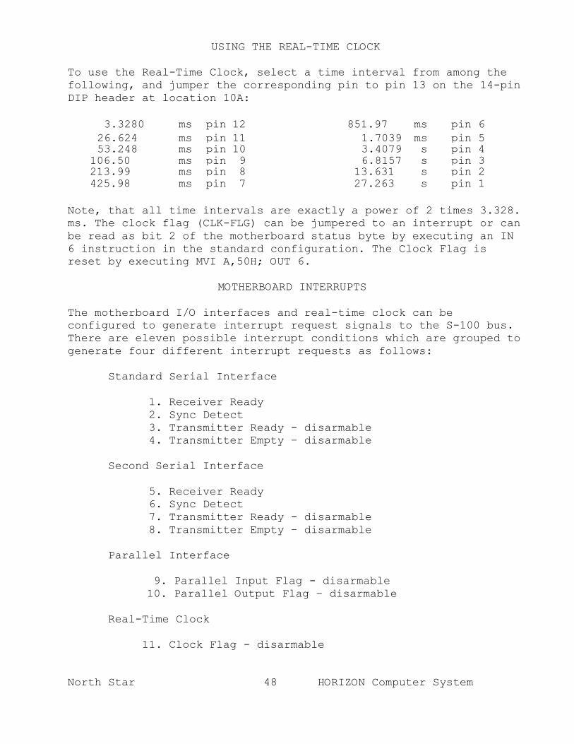
USING THE REAL-TIME CLOCK
To use the Real-Time Clock, select a time interval from among the following, and jumper the corresponding pin to pin 13 on the 14-pin DIP header at location 10A:
3.3280 ms pin 12 851.97 ms pin 626.624 ms pin 11 1.7039 ms pin 553.248 ms pin 10 3.4079 s pin 4
106.50 ms pin 9 6.8157 s pin 3213.99 ms pin 8 13.631 s pin 2425.98 ms pin 7 27.263 s pin 1
Note, that all time intervals are exactly a power of 2 times 3.328. ms. The clock flag (CLK-FLG) can be jumpered to an interrupt or can be read as bit 2 of the motherboard status byte by executing an IN 6 instruction in the standard configuration. The Clock Flag is reset by executing MVI A,50H; OUT 6.
MOTHERBOARD INTERRUPTS
The motherboard I/O interfaces and real-time clock can be configured to generate interrupt request signals to the S-100 bus. There are eleven possible interrupt conditions which are grouped to generate four different interrupt requests as follows:
Standard Serial Interface
1. Receiver Ready 2. Sync Detect 3. Transmitter Ready - disarmable 4. Transmitter Empty – disarmable
Second Serial Interface
5. Receiver Ready 6. Sync Detect 7. Transmitter Ready - disarmable 8. Transmitter Empty – disarmable
Parallel Interface
9. Parallel Input Flag - disarmable 10. Parallel Output Flag – disarmable
Real-Time Clock
11. Clock Flag - disarmable

North Star 49 HORIZON Computer System
Note, that this grouping can be rearranged by cutting and/or rewiring motherboard jumpers J5-J14. See the schematic drawings for details. Each of the above four interrupt groups can be tied to any one of the ten interrupt request lines on the S-100 bus by appropriately configuring the 16-pin Interrupt header at location IA. See the schematic drawings for details. Also, see the Motherboard Control Byte section for programming details for arming and disarming interrupts. Note, that interrupts during disk activity can cause detected read errors as well as undetected write errors. Therefore, it is recommended that interrupts always be disabled during use of the disk(s).
HORIZON GROUNDING
Improper grounding of a complete HORIZON computer system can adversely affect reliability as a result of ground noise. A complete system is properly grounded if chassis ground and signal ground are connected together in one place only. Therefore, the following grounding procedure is recommended. 1. Connect the HORIZON chassis to signal ground by soldering a
jumper wire between the two holes of the location C47, at the extreme left rear corner of the motherboard. If the HORIZON is being used in an environment where static electricity is a problem (e.g. synthetic fiber rugs or dry weather) then install a .047 ceramic disc capacitor at location C47, instead.
2. Be sure that chassis ground and signal ground are not connected on each piece of external equipment connected to the HORIZON. Examples of external equipment are a CRT terminal, a printer, or a third disk drive.
3. For shock protection, be sure that the chassis of each piece of
external equipment is grounded by using a 3-wire power cord or by connecting it to the HORIZON chassis with a wire. Note that the HORIZON chassis is grounded with a 3-wire power connection.

North Star 50 HORIZON Computer System
APPENDIX A BILLS OF MATERIALS
HRZ MB PC BOARD ASSEMBLY
ITEM PART# QTY DESCRIPTION DESIG LOCA
1 01001 13 Capacitor, .047uF Ceramic Disk
Cll-22, C48
3A,5A,l0A, 3B,4B,9B, 1D,5C,IOD, 5D,7D,1OD, 7A
2 01005 12 Capacitor, 470pF Ceramic Disk
C27-30, C35-38, C43-46
3B 1D 1C
3 01021 2 Capacitor, 2.2UF Dipped Tantalum
C2,C4 1B
4 01022 3 Capacitor, 6.8uF Dipped Tantalum
C3,C7, C10 Heat Sinks
5 01043 1 Capacitor, 2.2UF, 35V DippedTantalum
C1 1B
6 05007 1 PC Board, HRZ MB
7 13007 12 Connector, 100 pin edge Pl-12
Lt.Spec. Clock
1D
Rt.Spec. Clock
2C
8 13008 3 Header, 14 pin (unloaded)
Real Time Clock
10A
9 13009 1 Header, 16 pin (unloaded) Interrupts 1A
10 13012 2 Lug, 3/16"x.032" Quick Connect
Front Heat Sink
12 13016 2 Connector, 15 pin Rt. Angle Parallel I/O Ports

North Star 51 HORIZON Computer System
APPENDIX A
ITEM PART# QTY DESCRIPTION DESIG LOCA
13 13017 2 Connector, 25 pin Rt. Angle Left & Right Serial
14 13026 4 Socket, 14 pin AMP 1D,2C,5B, l0A
15 13028 4 Socket, 16 pin AMP 1A,2D,3D,4D
16 13030 5 Socket, 20 pin AMP 5A,6A,7A, 8A,9A
17 13034 2 Socket, 28 pin AMP 3A,4A
18 38001 8 Lockwasher, Internal Tooth #4
Right Angle Conn.
19 38002 7 Lockwasher, Internal Tooth #6
Heat Sink Mount
20 38009 8 Hex-Nut, 4-40 MS Right Angle Conn.
21 38011 8 Hex-Nut, 6-32x1/4 AF MS Right Angle Mount
22 38016 8 4-40x3/8" BHMS Right Angle Conn.
23 38018 7 6-32x3/8" BHMS Heat Sink Mount
24 38040 2 Heat Sink, 6016B Heat Sink Area
25 38041 3 Heat Sink, 6030B Heat Sink Area
26 43003 2 IC, 74LS03 2B,7B
27 43004 1 IC, 74LS04 5C
28 43005 1 IC, 74LS05 2A
29 43009 1 IC, 74LS14 7C
30 43015 2 IC, 74LS74 10C,10D
31 43019 1 IC, 74LS132 8D
32 43020 2 IC, 74LS136 6B,6C

North Star 52 HORIZON Computer System
APPENDIX A
ITEM PART# QTY DESCRIPTION DESIG LOCA
33 43021 1 IC, 74LS138 9B
34 43022 2 IC, 74LS139 9D
35 43027 2 IC, 74LS161 (or 74LS163)
6D,7D
36 43033 3 IC, 74LS241 5A,6A,7A
37 43038 1 IC, 74LS259 8B
38 43043 2 IC, 74LS373 8A,9A
39 43044 1 IC, 74LS393 5D
40 43058 1 IC, 7437 8C
41 43070 3 IC, 1488 1B,3B,4B
42 43071 3 IC, 1489 1C,3C,4C
43 43095 2 IC, 8251 3A,4A
44 43096 1 IC, 14020 10B
45 43100 2 Configuration Header Assembly
L&R Ser. Config.
3D,4D,4D
46 43101 1 Baud Rate Header Assembly Baud Rate 2D
47 43102 1 Port Select Header Assembly Port Sel. 5B
48 61013 2 Resistor, 220 ohm, 1/4W 5% R17,R25 1D
49 61015 1 Resistor, 470 ohm, 1/4W 5% R34 Front
50 61016 2 Resistor, 560 ohm, 1/4W 5% R16,R24 1D
51 61019 3 Resistor, 1.2K ohm, 1/4W 5% R2-4 6B,6C,l0A
52 61020 3 Resistor, 2.2K ohm, 1/4W 5% R1,R5,R30 5B,l0A,5B
53 61024 2 Resistor, 4.7K ohm, 1/4W 5% Rll,R19 3C
54 61025 2 Resistor, 5.6K ohm, 1/4W 5% R14,R22 3B,4B

North Star 53 HORIZON Computer System
APPENDIX A
ITEM PART# OTY DESCRIPTION DESIG LOCA
55 61035 2 Resistor, 1K ohm, 1/4W 5% R15,R23 1D
56 61036 1 Resistor, 100 ohm, 2W 5% R33 Front
57 61037 2 Resistor, 330 ohm, 2W 5% R31,R32 Front
58 65002 3 Regulator, 7805 Heat Sink
59 65004 2 Regulator, 7812 Ck or 340K-12
Heat Sink
60 65005 1 Regulator, 78L12 Heat Sink
61 65007 1 Regulator, 79L12 1B
62 77081 1" Solid Wire, 26 AWG w/green PVC insulation

North Star 54 HORIZON Computer System
APPENDIX A HORIZON MOTHERBOARD
CONFIGURATION HEADER ASSEMBLY BILL OF MATERIALS
ITEM PART NO QTY UNIT DESCRIPTION
1 13089 2 each 16 Pin DIP Header
2 77069 4 inch 22 AWG Bus Wire (non insulated)
2 inch 22 AWG Bus Wire (insulated)
HORIZON MOTHERBOARD BAUD RATE
HEADER ASSEMBLY BILL OF MATERIALS
ITEM PART NO QTY UNIT DESCRIPTION
1 13009 1 each 16 Pin DIP Header
2 77069 2 each 22 AWG Bus Wire (non insulated)
HORIZON MOTHERBOARD PORT SELECT HEADER ASSEMBLY
BILL OF MATERIALS ITEM PART NO QTY UNIT DESCRIPTION
1 13008 1 each 14 Pin DIP Header
2 77069 2 inch 22 AWG Bus Wire (non insulated)