Nokia EGPRS3 Details
55
1 © NOKI A EGPRS radi o_v_ 2. PPT / 23.3.200 1 Company Confidential EGPRS Radio interface Packet data logical channels Data transfer principles RLC Radio block structure Multislot MS MCS selection Multiplexing GPRS/EGPRS Link adaptation
Transcript of Nokia EGPRS3 Details

5/12/2018 Nokia EGPRS3 Details - slidepdf.com
http://slidepdf.com/reader/full/nokia-egprs3-details 1/55
1 © NOKIA EGPRS radio_v_2.PPT/ 23.3.2001 Company Confidential
EGPRS Radio interface
Packet data logical channels
Data transfer principles
RLC Radio block structure
Multislot MS MCS selection
Multiplexing GPRS/EGPRS
Link adaptation

5/12/2018 Nokia EGPRS3 Details - slidepdf.com
http://slidepdf.com/reader/full/nokia-egprs3-details 2/55
2 © NOKIA EGPRS radio_v_2.PPT/ 23.3.2001 Company Confidential
Packet data logical channels 1/3
PBCHPacket Broadcast Channels
PCCCH
Packet Common Control Chan
PDCCHPacket Dedicated Control Cha
PTCHPacket Traffic Channels

5/12/2018 Nokia EGPRS3 Details - slidepdf.com
http://slidepdf.com/reader/full/nokia-egprs3-details 3/55
3 © NOKIA EGPRS radio_v_2.PPT/ 23.3.2001 Company Confidential
Packet data logical channels 2/6
PBCCH available in BSS S10 GPRS and EGPRS will not impact on AGCH and PCH
Increased data rates will lead to heavier signalling demandfor given traffic occupancy and applications
Note - PBCCH traffic is not carried on TRXSIG Note - PBCCH must be on the same TRX as the BCCH
GMSK is used on packet control channels. 8-PSKmodulation is used only on the packet traffic data channelPDTCH.
PBCCH/PCCCH
PBCCH PPCH PDTCH PRACH
BCCH/CCCH
Common Channels
PAGCH

5/12/2018 Nokia EGPRS3 Details - slidepdf.com
http://slidepdf.com/reader/full/nokia-egprs3-details 4/55
4 © NOKIA EGPRS radio_v_2.PPT/ 23.3.2001 Company Confidential
Packet Broadcast control channel
PBCCH broadcast packet data specific System Information.If PBCCH is not allocated, the packet data specific system information is
broadcast on BCCH.
A broadcast control channel is a point-to-multipoint uni-directional control channel, from the fixed sub-system to theMobile Stations. Broadcast control channels are physicallysub-divided into Broadcast Control Channel (BCCH),Packet Broadcast Control Channel (PBCCH) and CompactPacket Broadcast Control Channel (CPBCCH).

5/12/2018 Nokia EGPRS3 Details - slidepdf.com
http://slidepdf.com/reader/full/nokia-egprs3-details 5/55
5 © NOKIA EGPRS radio_v_2.PPT/ 23.3.2001 Company Confidential
Packet data Common Control logicalchannels
PAGCH is used in the packet transfer establishment phase tosend resource assignment to an MS prior to packet transfer.
PNCH is used to send a PTM-M (Point To Multipoint -Multicast) notification to a group of MSs prior to a PTM-Mpacket transfer. ( NOT IMPLEMENTED in S10 )
PRACH is used by MS to initiate uplink transfer for sendingdata or signalling information.
PPCH is used to page an MS prior to downlink packet transfer.

5/12/2018 Nokia EGPRS3 Details - slidepdf.com
http://slidepdf.com/reader/full/nokia-egprs3-details 6/55
6 © NOKIA EGPRS radio_v_2.PPT/ 23.3.2001 Company Confidential
Paging Coordination
PPCH is used to page an MS prior to downlink packet transfer.PPCH CPPCH use paging groups in order to allow usage of DRX mode. PPCH canbe used for paging of both circuit switched and packet data services. The paging for circuit switched services on PPCH is applicable for class A and B GPRS MSs inNetwork operation mode I, see 3GPP TS 23.060
Mode Circuit Paging Channel GPRS Paging Channel Paging co-ordination
Packet Paging Channel Packet Paging Channel
I CCCH Paging Channel CCCH Paging Channel Yes
Packet Data Channel Not Applicable
II CCCH Paging Channel CCCH Paging Channel No
III CCCH Paging Channel Packet Paging Channel No
CCCH Paging Channel CCCH Paging Channel
Paging co-ordination = CS pages can be sent through SGSN and via PPCH

5/12/2018 Nokia EGPRS3 Details - slidepdf.com
http://slidepdf.com/reader/full/nokia-egprs3-details 7/55
7 © NOKIA EGPRS radio_v_2.PPT/ 23.3.2001 Company Confidential
Packet data dedicated channels
PACCH conveys signalling information related to a given MS.e.g. acknowledgements, power control, resource assignment and reassignmentmessages.. The PACCH shares resources with PDTCHs, that are currentlyassigned to one MS. Additionally, an MS that is currently involved in packet transfer,can be paged for circuit switched services on PACCH.
PTCCH is used to transmit random access burst to allow
estimation of the timing advance for MS's in packet transfer mode.
PDTCH is a channel allocated for data transfer. It is temporarilydedicated to one MS or to a group of MSs in the PTM-M case. In the multislotoperation, one MS may use multiple PDTCHs in parallel for individual packet
transfer.

5/12/2018 Nokia EGPRS3 Details - slidepdf.com
http://slidepdf.com/reader/full/nokia-egprs3-details 8/55
8 © NOKIA EGPRS radio_v_2.PPT/ 23.3.2001 Company Confidential
Mapping of PBCCH/PCCCH DL
B0 B1 B2 T B3 B4 B5 X B6 B7 B8 T B9 B10 B11 X
X = Idle frame
T = Frame used for PTCCH
B0 - B11 = Radio blocks
A physical channel allocated to carry packet logical channels is called a packetswitched channel (PDCH). A PDCH shall carry packet logical channels only.Packet switched logical channels are mapped dynamically onto a 52-multiframe. The 52-multiframe consists of 12 blocks of 4 consecutive frames, 2idle frames and 2 frames used for the PTCCH, as shown in figure. PCU handlesradio blocks 0 ± 11. BTS handles the rest of the radio blocks.

5/12/2018 Nokia EGPRS3 Details - slidepdf.com
http://slidepdf.com/reader/full/nokia-egprs3-details 9/55
9 © NOKIA EGPRS radio_v_2.PPT/ 23.3.2001 Company Confidential
y BS_PBCCH_BLKS, number of PBCCH blocks per multiframe.Depends on the number of PSIs and repeat period.
y BS_PAG_BLKS_RES, number of blocks in addition toBS_PBCCH_BLKS, where paging shall not occur.
y BS_PCC_CHANS number of physical channels carryingPCCCHs including the physical channel carrying the PBCCH.
FIXED to 1
For example:
BS_PBCCH_BLKS = 3 (number of blocks allocated to PBCCH per multiframe)
BS_PAG_BLKS_RES = 4 (number of blocks allocated to PAGCH per multiframe)
Empty blocks can be used for packet assignment, packet paging, packet data or associated signalling. PAGCHblocks can be used for packet assignment, packet data or associated signalling
PBCCH PAGCH PBCCH PAGCH PBCCH PAGCH PAGCH
BL 0 BL 1 BL 2 BL 3 BL 4 BL 5 BL 6 BL 7 BL 8 BL 9 BL 10 BL 11
Mapping of PBCCH/PCCCH DL (2/3)

5/12/2018 Nokia EGPRS3 Details - slidepdf.com
http://slidepdf.com/reader/full/nokia-egprs3-details 10/55
10 © NOKIA EGPRS radio_v_2.PPT/ 23.3.2001 Company Confidential
Data Transfer - Temporary Block Flow
A Temporary Block Flow (TBF): is a one-way session for packet data transfer between MS and
BSC (PCU)
uses either uplink or downlink but not both (except for
associated signalling)
can use one or more TSLs
Compare with circuit-switched - normally one connection usesboth the uplink and the downlink timeslot(s) for traffic.
In two-way data transfer, uplink and downlink data are sent in
separate TBFs - as below.
BSCBSC
Uplink TBF (+ PACCH for downlink TBF)
Downlink TBF (+ PACCH for uplink TBF)

5/12/2018 Nokia EGPRS3 Details - slidepdf.com
http://slidepdf.com/reader/full/nokia-egprs3-details 11/55
11 © NOKIA EGPRS radio_v_2.PPT/ 23.3.2001 Company Confidential
Establishing a TBF and Sending Data-UL
Channel request - RACH
Immediate Assignment - AGCH
Data - PDTCH
Signalling + Ack/Nack - PACCH
BTSBTS
Final Data - PDTCH
Final Ack/Nack - PACCH
Packet control Ack - PACCH

5/12/2018 Nokia EGPRS3 Details - slidepdf.com
http://slidepdf.com/reader/full/nokia-egprs3-details 12/55
12 © NOKIA EGPRS radio_v_2.PPT/ 23.3.2001 Company Confidential
Establishing a TBF and Sending Data -DL
Immediate Assignment - AGCH
Paging - PCH
UL TBF for MS location
Packet control Ack - PACCH (for TA)
Packet polling - PACCH)
Packet downlink assignment - PACCH
Data - PDTCH/ Signalling -PACCH
Ack/Nack - PACCH
BTSBTS

5/12/2018 Nokia EGPRS3 Details - slidepdf.com
http://slidepdf.com/reader/full/nokia-egprs3-details 13/55
13 © NOKIA EGPRS radio_v_2.PPT/ 23.3.2001 Company Confidential
Radio Resource operating modes
Packet idle mode No Temporary Block Flow exists MS listens to the PBCCH and to the paging sub-channel for the paging
group the MS belongs to in idle mode. If PCCCH is not present in the cell,the mobile station listens to the BCCH and to the relevant paging sub-channels
Packet transfer mode MS is allocated radio resource providing a Temporary Block Flow on one or
more physical channels When selecting a new cell, mobile station leaves the packet transfer mode,
enters the packet idle mode where it switches to the new cell, read thesystem information and may then resume to packet transfer mode in thenew cell
Dual transfer mode MS has an ongoing RR connection and is allocated radio resource
providing a Temporary Block Flow on one or more physical channels While in dual transfer mode the MS performs all the tasks of dedicated
mode
5/12/2018 Nokia EGPRS3 Details - slidepdf.com
http://slidepdf.com/reader/full/nokia-egprs3-details 14/55
14 © NOKIA EGPRS radio_v_2.PPT/ 23.3.2001Company Confidential
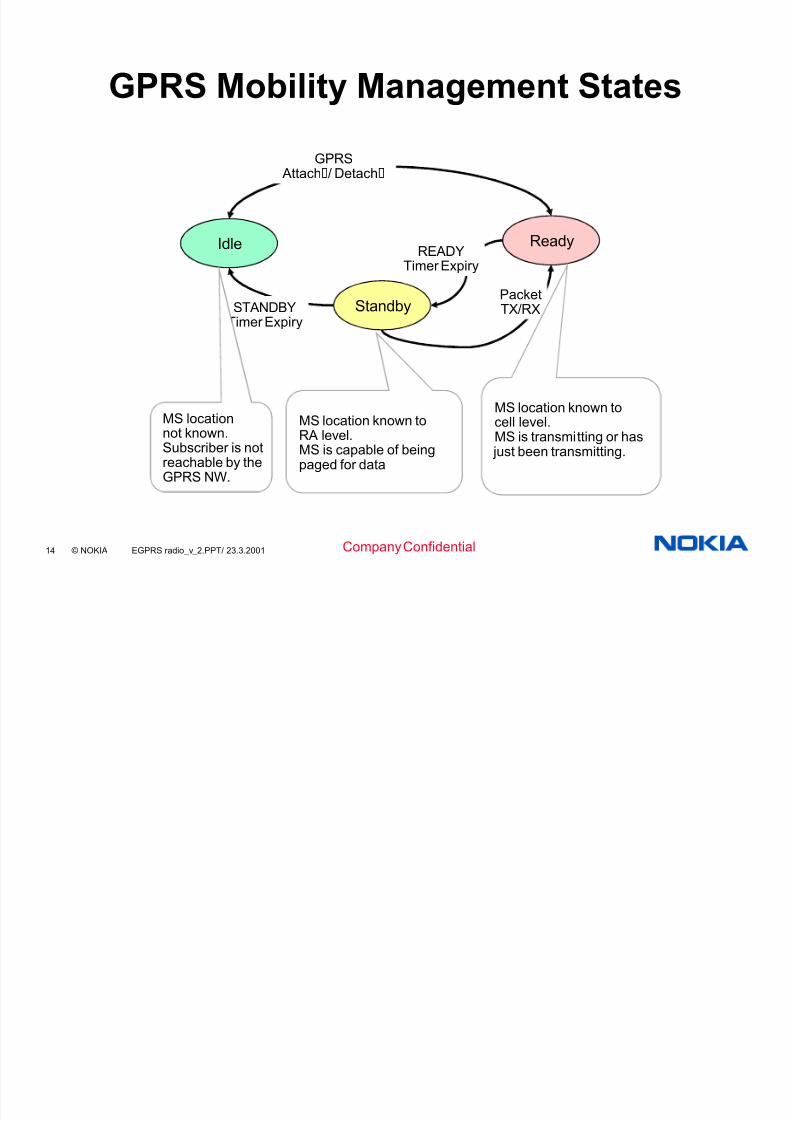
GPRS Mobility Management States
Idle
Standby
Ready
PacketTX/RXSTANDBY
Timer Expiry
GPRS Attach/ Detach
READYTimer Expiry
MS location known toRA level.MS is capable of beingpaged for data
MS locationnot known.Subscriber is notreachable by theGPRS NW.
MS location known tocell level.MS is transmitting or has
just been transmitting.

5/12/2018 Nokia EGPRS3 Details - slidepdf.com
http://slidepdf.com/reader/full/nokia-egprs3-details 15/55
15 © NOKIA EGPRS radio_v_2.PPT/ 23.3.2001Company Confidential
RR operating modes and MM Statescorrespondence
Non-DTM capable MS:
RR BSSPacket
transfer modeMeasurement
report receptionNo state No state
RR MSPacket
transfer modePacket idle mode
Packetidle mode
MM (NSS
and MS)Ready Standby
DTM capable MS:
RR BSSMeasurement
report receptionNo state No state
RR MS
Dualtransfer
mode
Dedicatedmode
Packettransfer
mode CS idle and packet idle
Dedicatedmode CS idle and
packet idleGMM (NSS
and MS)Ready Standby

5/12/2018 Nokia EGPRS3 Details - slidepdf.com
http://slidepdf.com/reader/full/nokia-egprs3-details 16/55
16 © NOKIA EGPRS radio_v_2.PPT/ 23.3.2001Company Confidential
EGPRS (Enhanced General Packet Radio Service) is an improved air interface for GPRS packet service. The peak throughput of EGPRS is 2.96 times the peak throughput of GPRS.
The figure below shows the (E)GPRS protocol stack when carrying IP data.Radio performance depends mostly on the RLC/MAC and physical layer of the radio interface (Um).
(E)GPRS Transmission plane
Scope of 3GPP TS23.060
Relay
Network
Service
GTP
Application
IP / X.25
SNDCP
LLC
RLC
MAC
GSM RF
SNDCP
LLC
BSSGP
L1bis
RLC
MAC
GSM RF
BSSGP
L1bis
Relay
L2
L1
IP
L2
L1
IP
GTP
IP / X.25
Um Gb Gn GiMS BSS SGSN GGSN
Network
Service
UDP /
TCP
UDP /
TCP
Scope of TS 03.64

5/12/2018 Nokia EGPRS3 Details - slidepdf.com
http://slidepdf.com/reader/full/nokia-egprs3-details 17/55
Logical Link Control (LLC) Layer
LLC
SNDCP
IP
TCP/UDP
APP
RLC
MAC
GSM RF
Reliable logical connection between SGSN and MS
Independent of underlying radio interface protocols
Control Address
FCSInformation
LLC Frame
1 1-3 1-1520 3 Octets

5/12/2018 Nokia EGPRS3 Details - slidepdf.com
http://slidepdf.com/reader/full/nokia-egprs3-details 18/55
Radio Link Control (RLC)/ MediumAccess Control (MAC) Layers
RLC
Reliable transmission of data across air interface
Segmentation/de-segmentation of data from/toLLC layer
MAC
Control of MS access to common air-interfacemedium
Flagging of PDTCH/PACCH occupancy
LLC
SNDCP
IP
TCP/UDP
APP
RLC
MAC
GSM RF

5/12/2018 Nokia EGPRS3 Details - slidepdf.com
http://slidepdf.com/reader/full/nokia-egprs3-details 19/55
19 © NOKIA EGPRS radio_v_2.PPT/ 23.3.2001Company Confidential
RLC/MAC
Implemented in the PCU (Packet Control Unit, part of BSC).
TBF (Temporary Block Flow) is a one-directional data flowbetween two RLC/MAC entities (PCU and MS).
TBF is established when new data arrives to RLC.
TBF is released when all the data in RLC has been sent. Acknowledged RLC mode:
ARQ, retransmissions and IR. RLC/MAC can guarantee error-free and in-order delivery of
upper layer blocks..
Unacknowledged RLC mode: No ARQ, retransmissions or IR. Corrupted blocks are lost or delivered in error.

5/12/2018 Nokia EGPRS3 Details - slidepdf.com
http://slidepdf.com/reader/full/nokia-egprs3-details 20/55
20 © NOKIA EGPRS radio_v_2.PPT/ 23.3.2001 Company Confidential
data to be transmitted
RLC: Segmentation & ARQ
Segmentation makes RLC blocksfrom LLC frames.
Size of RLC block matches theMCS.
LLC frames can be small or large. Large LLC frames takemany RLC blocks.
RLC blocks can contain LLCframe boundaries (even multiplesmall LLC frames).
ARQ (Automatic Repeat reQuest)takes care of backward error correction, i.e. requesting andperforming retransmissions of incorrectly received blocks.
Used in both GPRS andEGPRS when in acknowledgedRLC mode.
Multiple blocks are
acknowledged at the same time.
1 20 43
? 0? 1
? 2?
3
4
0
2
1 20 43
transmitter
receiver
time
all data correctly received

5/12/2018 Nokia EGPRS3 Details - slidepdf.com
http://slidepdf.com/reader/full/nokia-egprs3-details 21/55
21 © NOKIA EGPRS radio_v_2.PPT/ 23.3.2001 Company Confidential
RLC: Retransmissions
originaltransmission
normalretransmission
retrans withresegmentation
MCS-1 MCS-1
MCS-2 MCS-2
MCS-3 MCS-3
MCS-4 MCS-4 2 * MCS-1
MCS-5 or 7 MCS-5 or 7 2 * MCS-2MCS-6 or 9 MCS-6 or 9 2 * MCS-3
MCS-8 MCS-8 MCS-6 (pad)2 * MCS-3 (pad)
In GPRS, retransmissions arealways in the same CS as theoriginal transmission, whichcauses problems if too high a CShas been selected.
To help this, EGPRS allows aretransmission to be performedin a lower MCS than original.
MCSs are divided in families: C: MCS-1, MCS-4 B: MCS-2, MCS-5, MCS-7 A: MCS-3, MCS-6, MCS-8, MCS-9
With normal (not resegmented) retransmissions the structure and content of the RLC block is identical to the original transmissions. Therefore IRcombining is possible.
In resegmentation, an RLC block is split in two halves. Padding meansadding dummy bits to an MCS-8 block so it looks like an MCS-6 block. IRcombining is not possible.

5/12/2018 Nokia EGPRS3 Details - slidepdf.com
http://slidepdf.com/reader/full/nokia-egprs3-details 22/55
22 © NOKIA EGPRS radio_v_2.PPT/ 23.3.2001 Company Confidential
MAC: Scheduling
(E)GPRS timeslots can be sharedby multiple MSs.
The radio resource is allocated ona radio block (4 bursts, 20 ms)resolution by the network.
In the downlink, all the MSs listencontinuously. TFI (Temporary FlowIdentifier) is used to address oneMS.
In the uplink, there are differentresource allocation modes: fixed,dynamic and extended dynamic
allocation.
Fixed allocation A large number of (not
necessarily continuous) radioblock periods are allocated to aMS in advance using a controlmessage. (Not used in Nokiaimplementation.)
Dynamic allocation NW sends USFs (Uplink Status
Flags) in each downlink block tosignal which MS is allowed totransmit during the next uplinkblock period.
The USF may be for a differentMS than the actual data in thedownlink radio block. Problemswith power control and smartantennas.
Extended dynamic allocation
multislot

5/12/2018 Nokia EGPRS3 Details - slidepdf.com
http://slidepdf.com/reader/full/nokia-egprs3-details 23/55
23 © NOKIA EGPRS radio_v_2.PPT/ 23.3.2001 Company Confidential
Throughput
Main performance indicator of GPRS & EGPRS.
Throughput is defined as the number of user data bitsdelivered per second (usually per time slot).
The definition of user data bit excludes the following overhead
from the gross rates: physical layer overhead due to channel coding, RLC/MAC layer overhead due to header information, overhead due to retransmissions.

5/12/2018 Nokia EGPRS3 Details - slidepdf.com
http://slidepdf.com/reader/full/nokia-egprs3-details 24/55
24 © NOKIA EGPRS radio_v_2.PPT/ 23.3.2001 Company Confidential
EGPRS Modulation and CodingSchemes
EGPRS has nine basic codingschemes, MCS-1...9.
In general, a higher coding schemehas higher coding rate, andconsequently higher peakthroughput, but it also tolerates less
noise or interference. The figure shows throughput vs. C/I
of EGPRS coding schemes inTU50iFH, without incrementalredundancy.
The basic unit of transmission is
radio block (= 4 bursts = 20 ms onaverage), which contains one or two RLC blocks.
0
10
20
30
40
50
60
0 5 10 15 20 25 30
MCS-1
MCS-2
MCS-3
MCS-4
MCS-5
MCS-6
MCS-7
MCS-8MCS-9

5/12/2018 Nokia EGPRS3 Details - slidepdf.com
http://slidepdf.com/reader/full/nokia-egprs3-details 25/55
25 © NOKIA EGPRS radio_v_2.PPT/ 23.3.2001 Company Confidential
Data treatment principle in RF layer
User data
"Additional info" that does not require extraprotection
Header part, robust coding for securetransmission

5/12/2018 Nokia EGPRS3 Details - slidepdf.com
http://slidepdf.com/reader/full/nokia-egprs3-details 26/55
26 © NOKIA EGPRS radio_v_2.PPT/ 23.3.2001 Company Confidential
EGPRS Channel Coding
EGPRS channel coding consistsof separate data and header coding, as shown in the figurefor MCS-9 downlink.
Coding of data part: Data part includes user
data, two bits from RLCheader, BCS (block check sequence)and tail bits.
Coded using 1/3 convolutional code. Punctured with a selectable puncturing scheme
(P1, P2 or P3). Two separate data parts for MCS-7...9.
Header part: Includes RLC/MAC header information and
information on the coding of the data part (likeused puncturing scheme).
Convulutional coding + puncturing.
USF
encoded USF P2 P3
P1 P2 P3
puncturing puncturing
puncturing
1st burst 2nd burst 3rd burst 4th burst
1/3 tailbitingconvolutional coding
blockcoding
P1
header FBI+E data 2 BCS tail
1/3 convolutionalcoding
FBI+E data 1 BCS tail
1/3 convolutionalcoding
mother code
mother code
protectedheader

5/12/2018 Nokia EGPRS3 Details - slidepdf.com
http://slidepdf.com/reader/full/nokia-egprs3-details 27/55
27 © NOKIA EGPRS radio_v_2.PPT/ 23.3.2001 Company Confidential
GPRS & EGPRS Coding Schemes
codingscheme
modulation RLC blks /radio blk
FECcode rate
user bits /20 ms
bit rate(bps)
CS-1 1 0.45 160 8,000
CS-2 1 0.65 240 12,000
CS-3 1 0.75 288 14,400
GPRS
CS-4 1 n/a 400 20,000
MCS-1 1 0.53 176 8,800
MCS-2 1 0.66 224 11,200
MCS-3 1 0.85 296 14,800
MCS-4
GMSK
1 1.00 352 17,600
MCS-5 1 0.38 448 22,400
MCS-6 1 0.49 592 29,600MCS-7 2 0.76 448+448 44,800
MCS-8 2 0.92 544+544 54,400
EGPRS
MCS-9
8-PSK
2 1.00 592+592 59,200

5/12/2018 Nokia EGPRS3 Details - slidepdf.com
http://slidepdf.com/reader/full/nokia-egprs3-details 28/55
28 © NOKIA EGPRS radio_v_2.PPT/ 23.3.2001 Company Confidential
EGPRS MCS´s
37 octets 37 octets 37 octets37 octets
MCS-3
MCS-6
Family A
MCS-9
28 octets 28 octets 28 octets28 octets
MCS-2
MCS-5
MCS-7
Family B
22 octets22 octets
MCS-1
MCS-4
Family C
34+3 octets34+3 octets
MCS-3
MCS-6
Family A
padding
MCS-8
34 octets 34 octets 34 octets34 octets
The MCSs are divided into different families
A,B and C.
Each family has a different basic unit of payload: 37 (and 34), 28 and 22 octetsrespectively.
Different code rates within a family areachieved by transmitting a different number of payload units within one Radio Block.
For families A and B, 1 or 2 or 4 payload unitsare transmittes, for family C, only 1 or 2payload units are transmitted
When 4 payload units are transmitted (MCS 7,
MSC-8 and MCS-9), these are splitted into twoseparate RLC blocks (with separate sequenceBSN numbers and BCS, Block CheckSequences)
The blocks are interleaved over two burstsonly, for MCS-8 and MCS-9.
For MCS-7 the blocks are interleaved over

5/12/2018 Nokia EGPRS3 Details - slidepdf.com
http://slidepdf.com/reader/full/nokia-egprs3-details 29/55
29 © NOKIA EGPRS radio_v_2.PPT/ 23.3.2001 Company Confidential
Interleaving over 2 bursts(header: 4bursts)
Decreasingredundancy
Addingredundancy
MCS-9 coding and puncturing
P2 P3P1 P2
puncturing puncturing
1836 bits
USF RLC/MACHdr.
36 bits
Rate 1/3 convolutional coding
135 bits
612 bits
612 bits124 bits36 bitsSB = 8
1392 bits
45 bits
Data = 592 bits BCS TB
612 bits
612 bits 612 bits
1836 bits
Rate 1/3 convolutional coding
EFBIData = 592 bits BCS TBEFBI
612 bits 612 bits 612 bits
P3 P1
3 bits
HCS
puncturing
Ref: TS 03.64
1 1 12 6
Data rate: skbms
/2,5920
5922!
v
Robust codingfor header
Normal burst:2x58x3 bits
Normal burst:2x58x3 bits
Normal burst:2x58x3 bits
Normal burst:2x58x3 bits
BP: 15/26 ms BP: 15/26 ms BP: 15/26 ms BP: 15/26 ms
skbms
/6,6920
1392!
20 ms

5/12/2018 Nokia EGPRS3 Details - slidepdf.com
http://slidepdf.com/reader/full/nokia-egprs3-details 30/55
30 © NOKIA EGPRS radio_v_2.PPT/ 23.3.2001 Company Confidential
Coding parameters
EGPRS modulation and coding schemes:
Scheme Code rate Header Code rate
Modulation RLC blocksper Radio
Block(20ms)
Raw Datawithin one
Radio Block
Family BCS Tailpayload
HCS Data ratekb/s
MCS-9 1.0 0.36 2 2x592 A 59.2
MCS-8 0.92 0.36 2 2x544 A 54.4
MCS-7 0.76 0.36 2 2x448 B
2x12 2x6
44.8
MCS-6 0.49 1/3 1 592544+48
A 29.627.2
MCS-5 0.37 1/3
8PSK
1 448 B 22.4
MCS-4 1.0 0.53 1 352 C 17.6
MCS-3 0.80 0.53 1 296272+24
A 14.813.6
MCS-2 0.66 0.53 1 224 B 11.2
MCS-1 0.53 0.53
GMSK
1 176 C
12 6
8
8.8
NOTE: the italic captions indicate the padding.
Ref: TS 03.64

5/12/2018 Nokia EGPRS3 Details - slidepdf.com
http://slidepdf.com/reader/full/nokia-egprs3-details 31/55
31 © NOKIA EGPRS radio_v_2.PPT/ 23.3.2001 Company Confidential
EGPRS RLC/MAC header
Bit8 7 6 5 4 3 2 1 Octet
TFI RRBP ES/P USF 1
BSN1 PR TFI 2BSN1 3
BSN2 BSN1 4
CPS BSN2 5
Bit8 7 6 5 4 3 2 1 Octet
TFI Countdown Value SI R 1
BSN1 TFI 2
BSN2 BSN1 3
BSN2 4
Spare PI RSB CPS 5
Spare 6
Downlink:
Uplink:
Ref: TS 04.60
Three header types for EGPRS
Example: Header type 1 (header for MCS-7, MCS-8 and MCS-9)

5/12/2018 Nokia EGPRS3 Details - slidepdf.com
http://slidepdf.com/reader/full/nokia-egprs3-details 32/55
32 © NOKIA EGPRS radio_v_2.PPT/ 23.3.2001 Company Confidential
Multiple Mobiles and UplinkTransmission
USF =1
USF = 2
USF =3
USF = 3
MSs
BTS
RLC Data Block
Mobile transmissions controlled by USF (Uplink State Flag)sent on DL
Mobile with correct USF will transmit in following block

5/12/2018 Nokia EGPRS3 Details - slidepdf.com
http://slidepdf.com/reader/full/nokia-egprs3-details 33/55
33 © NOKIA EGPRS radio_v_2.PPT/ 23.3.2001 Company Confidential
Multiple Mobiles and DownlinkTransmission
TFI2
TFI5
TFI3
TFI2
MSs
BTS
TFI value included in RLC block header - indicateswith which TBF the RLC block is associated
RLC Data Block

5/12/2018 Nokia EGPRS3 Details - slidepdf.com
http://slidepdf.com/reader/full/nokia-egprs3-details 34/55
34 © NOKIA EGPRS radio_v_2.PPT/ 23.3.2001 Company Confidential
MS classes for multislot capability Rx: Rx describes the maximum number of receive timeslots that the MS can
use per TDMA frame. The MS must be able to support all integer values of receive TS from 0 to Rx (depending on the services supported by the MS). Thereceive TS need not be contiguous. For type 1 MS, the receive TS shall beallocated within window of size Rx, and no transmit TS shall occur betweenreceive TS within a TDMA frame.
Tx: Tx describes the maximum number of transmit timeslots that the MS canuse per TDMA frame. The MS must be able to support all integer values of transmit TS from 0 to Tx (depending on the services supported by the MS). Thetransmit TS need not be contiguous. For type 1 MS, the transmit TS shall beallocated within window of size Tx, and no receive TS shall occur betweentransmit TS within a TDMA frame.
Sum: Sum is the total number of uplink and downlink TS that can actually beused by the MS per TDMA frame. The MS must be able to support allcombinations of integer values of Rx and Tx TS where 1 <= Rx + Tx <= Sum(depending on the services supported by the MS). Sum is not applicable to allclasses.

5/12/2018 Nokia EGPRS3 Details - slidepdf.com
http://slidepdf.com/reader/full/nokia-egprs3-details 35/55
35 © NOKIA EGPRS radio_v_2.PPT/ 23.3.2001 Company Confidential
Multislot Classes
29 multislot classes specified: e.g.Multislot
classMaximum number of slots Minimum number of slots Type
Rx Tx Sum Tta Ttb Tra Trb
1 1 1 2 3 2 4 2 12 2 1 3 3 2 3 1 13 2 2 3 3 2 3 1 14 3 1 4 3 1 3 1 15 2 2 4 3 1 3 1 16 3 2 4 3 1 3 1 17 3 3 4 3 1 3 1 18 4 1 5 3 1 2 1 19 3 2 5 3 1 2 1 1
10 4 2 5 3 1 2 1 111 4 3 5 3 1 2 1 112 4 4 5 2 1 2 1 113 3 3 NA NA a) 3 a) 214 4 4 NA NA a) 3 a) 215 5 5 NA NA a) 3 a) 216 6 6 NA NA a) 2 a) 2
17 7 7
NA NA a) 1 0 218 8 8 NA NA 0 0 0 219 6 2 NA 3 b) 2 c) 120 6 3 NA 3 b) 2 c) 121 6 4 NA 3 b) 2 c) 122 6 4 NA 2 b) 2 c) 123 6 6 NA 2 b) 2 c) 124 8 2 NA 3 b) 2 c) 125 8 3 NA 3 b) 2 c) 126 8 4 NA 3 b) 2 c) 127 8 4 NA 2 b) 2 c) 1
28 8 6 NA 2 b) 2 c) 129 8 8 NA 2 b) 2 c) 1
Tta: Tta relates to the time needed for the MS to perform adjacent cell signal level
measurement and get ready to transmit.
Ttb: Ttb relates to the time needed for the MS to get ready to transmit. This minimum
requirement will only be used when adjacent cell power measurements are not required by the
service selected.
Tra: Tra relates to the time needed for the MS to perform adjacent cell signal levelmeasurement and get ready to receive.
Trb: Trb relates to the time needed for the MS to get ready to receive. This minimum
requirement will only be used when adjacent cell power measurements are not required by the
service selected.

5/12/2018 Nokia EGPRS3 Details - slidepdf.com
http://slidepdf.com/reader/full/nokia-egprs3-details 36/55
36 © NOKIA EGPRS radio_v_2.PPT/ 23.3.2001 Company Confidential
MS multislot example
Multislot class 5 MS in circuit switched configuration Five basic configurations of channels are possible
Rx
Tx
Rx=2
Tt=1 Tx=2
Rx
Tx
Rx=2
Tt=1
Tx<2
Rx
Tx
Rx<2 Tt>1 Tx=2
These five combinations can be repeatedat the six other positions that can be fitted
within the same TDMA frame
Rx
Tx
Rx=2 Tt>1
Tx<2
Tra>3
Tra=3 Tra=3
Tra=3
Rx
Tx
Rx<2 Tx=2 Tra>3
Tt=1
All possible timeslots used Downlink biased assymetry
Alternative downlink biased assymetry Uplink biased assymetry(not prohibited by multislot class)
Alternative uplink biased assymetry(not prohibited by multislot class)Ref: TS 05.02

5/12/2018 Nokia EGPRS3 Details - slidepdf.com
http://slidepdf.com/reader/full/nokia-egprs3-details 37/55
37 © NOKIA EGPRS radio_v_2.PPT/ 23.3.2001 Company Confidential
Multiplexing GPRS/EGPRS
GPRS and EGPRS mobile stations can be multiplexed dynamically on thesame PDCH
Timeslot scheduling algorithm determines if there is a standard GPRS MSand EGPRS MS multiplexed on the timeslot, then at least one Radio Blockevery 360ms on the downlink must use GMSK coding scheme.
For MS synchronisation resons, if standard GPRS MS are multiplexed on the PDCH,
at least one Radio Block every 360 ms on the Downlink must use GMSK (i.e.standard GPRS or MCS-1to MCS-4) (GSM 04.60 v. 8.5.0)
When USF is sent to GPRS MS the downlink coding scheme used inmultiplexed timeslot shall be restricted to MCS1 to MCS4

5/12/2018 Nokia EGPRS3 Details - slidepdf.com
http://slidepdf.com/reader/full/nokia-egprs3-details 38/55
38 © NOKIA EGPRS radio_v_2.PPT/ 23.3.2001 Company Confidential
Incremental Redundancy
Link Adaptation

5/12/2018 Nokia EGPRS3 Details - slidepdf.com
http://slidepdf.com/reader/full/nokia-egprs3-details 39/55
39 © NOKIA EGPRS radio_v_2.PPT/ 23.3.2001 Company Confidential
Incremental Redundancy (1) IR is a physical layer performance enhancement for the
acknowledged RLC mode of EGPRS.
The basis for Incremental Redundancy (IR) is in the selective-reject- ARQ protocol of the RLC layer. The ARQ protocol takes care of requesting and retransmitting incorrectly received blocks.
By using the Backward Error Correction (BEC) procedures the
selective retransmission of unsuccessfully delivered RLC/MACblocks is obtained
IR improves the reception of retransmissions by combining theinformation in the original transmission (which failed) with thereceived additional information, thereby increasing the probability of correct reception.
The most important standardised feature of IncrementalRedundancy is that MS has mandatory IR combining in its receiver.IR has also been taken into account in the design of the codingschemes and block formats.

5/12/2018 Nokia EGPRS3 Details - slidepdf.com
http://slidepdf.com/reader/full/nokia-egprs3-details 40/55
40 © NOKIA EGPRS radio_v_2.PPT/ 23.3.2001 Company Confidential
Incremental Redundancy (2)
The figure shows an example of IR transmission andcombining with different puncturing schemes for differenttransmission. The shown case corresponds to MCS-4 or MCS-9, where the basic code rate is 1/1.
original data
1/3 coded data
1st xmission
2nd xmission
3rd xmission
1st decoding attempt
2nd decoding attempt
3rd decoding attempt
r = 1/3
r = 1/2
r = 1/1
r = 1/1
r = 1/1
r = 1/1

5/12/2018 Nokia EGPRS3 Details - slidepdf.com
http://slidepdf.com/reader/full/nokia-egprs3-details 41/55
41 © NOKIA EGPRS radio_v_2.PPT/ 23.3.2001 Company Confidential
0
10
20
30
40
50
60
0 5 10 15 20 25 30
MCS-9
MCS-9 IR
MCS-9 IR 20 ksv
Incremental Redundancy (4)
MCS-9 with and without IR. Throughput vs. C/I in TU3 ideal FH.
Gain of IR is up to 11 dB in thiscase.
The dashed line shows IRperformance with a limited IRreceiver memory (20480 softvalues). The IR gain is now limitedto 8 dB.

5/12/2018 Nokia EGPRS3 Details - slidepdf.com
http://slidepdf.com/reader/full/nokia-egprs3-details 42/55
42 © NOKIA EGPRS radio_v_2.PPT/ 23.3.2001 Company Confidential
Incremental Redundancy (5)
Ideal MCS selection with andwithout IR.
Throughput vs. C/I in TU3 ideal FH.
Gain of IR is at most 2 dB.
Gains of IR and LA are not additive.
In reality, MCS selection is sub-optimal, so the real IR gain isbetween 2 and 8 dB.
In other words, IR has two benefits: easier MCS selection, performance enhancement.
0
10
20
30
40
50
60
0 5 10 15 20 25 30
ideal MCS
ideal MCS IR

5/12/2018 Nokia EGPRS3 Details - slidepdf.com
http://slidepdf.com/reader/full/nokia-egprs3-details 43/55
43 © NOKIA EGPRS radio_v_2.PPT/ 23.3.2001 Company Confidential
Link adaptation-MCS Selection-
Link adaptation comprises an initial MCS selection and MCSadaptation
In the uplink, the entire MCS selection is controlled by oneparameter, and MS performs MCS selection according to
rules in 04.60. In the downlink, MCS selection is performed by the network.
This makes trying different MCSs easier and allows finer control in choosing the MCS for retransmissions. Alsospecial situations such as lack of IR memory can behandled separately on a block-by-block basis.
For initial transmissions: If IR memory is not full, use MCSpref_IR . If IR memory is full, use MCSpref_noIR .

5/12/2018 Nokia EGPRS3 Details - slidepdf.com
http://slidepdf.com/reader/full/nokia-egprs3-details 44/55
44 © NOKIA EGPRS radio_v_2.PPT/ 23.3.2001 Company Confidential
Link adaptation-adaptation-
S10 Link adaptation algorithm:
is based on BEP mean and variance, reported by MS does not need TS specific BEP values
BEP mapping tables are based on extensive link levelsimulations (they may later be updated according to e.g.field measurements)
does not take BLER (ACK/NACK information) into account has 6 operator parameters which provide good and stable
control of the algorithm is simple to implement and do not require much computing
or additional memory

5/12/2018 Nokia EGPRS3 Details - slidepdf.com
http://slidepdf.com/reader/full/nokia-egprs3-details 45/55
45 © NOKIA EGPRS radio_v_2.PPT/ 23.3.2001 Company Confidential
Link Adaptation: Introduction 1/3
The task of the link adaptation algorithm is to select the optimalMCS for each radio condition to maximise channel throughput.
Normally, LA adapts to path loss and shadowing but not fastfading. This corresponds to the "ideal LA" curves in link levelsimulations.
For very fast moving mobiles LA cannot adapt to shadowing,which will be handled by IR.
For very slow moving mobiles, the effect of fast fading cannotbe separated from the effect of shadowing, therefore LA willadapt to fast fading.
LA must take into account if IR combining is performed at thereceiver.
LA must take into account the effect of finite IR memory.
LA must also support the unacknowledged RLC mode

5/12/2018 Nokia EGPRS3 Details - slidepdf.com
http://slidepdf.com/reader/full/nokia-egprs3-details 46/55
46 © NOKIA EGPRS radio_v_2.PPT/ 23.3.2001 Company Confidential
Link Adaptation: MCS selection
The default initial MCS value for RLC link adaptation isreceived from parameter database and it is an operator definable parameter
one default initial MCS value for available frequency bandsis used
MAC receives the initial MCS setting when MAC requestsfor an allocation
MAC informs RLC of initial MCS when TBF is created
EGPRS Link Adaptation is activated in downlink when RLCreceives EGPRS Packet Downlink ACK/NACK message onEGPRS acknowledge mode TBF
In unacknowledged mode Link Adaptation is used to makeMCS selection to downlink packets without packetretransmission
The initial MCS value for UL data transfer is received by MS in
PACKET UPLINK ASSIGNMENT or in PACKET TIMESLOT

5/12/2018 Nokia EGPRS3 Details - slidepdf.com
http://slidepdf.com/reader/full/nokia-egprs3-details 47/55
47 © NOKIA EGPRS radio_v_2.PPT/ 23.3.2001 Company Confidential
Link Adaptation: RetransmissionControl
Acknowledged RLC mode uses selective packet confirmationwhere the receiving side confirms incoming packets.
RLC packets are BSN numbered within TBF in use, and theBSN numbers are used to identify packets not receivedcorrectly
Each RLC data block contains a block sequence number (BSN) field that is 7 bits in length
[04.60 / 9.1.4]
Receiving side sends confirmations either EGPRS PACKETDOWNLINK ACK/NACK or PACKET UPLINK ACK/NACKdepending on TBF transfer direction.
The EGPRS PACKET DOWNLINK ACK/NACK confirmation packet is
sent by the MS when requested by the network.
The PACKET UPLINK ACK/NACK confirmation packet is sent by thenetwork whenever the network decides to do so
In downlink TBF the network can query the MS to send aEGPRS Channel Quality Report IE

5/12/2018 Nokia EGPRS3 Details - slidepdf.com
http://slidepdf.com/reader/full/nokia-egprs3-details 48/55
48 © NOKIA EGPRS radio_v_2.PPT/ 23.3.2001 Company Confidential
Changing the MCS of an RLC block MCSs are divided into three families: (MCS-1, MCS-4),
(MCS-2, MCS-5, MCS-7) and (MCS-3, MCS-6, MCS-8, MCS-9). Switching across families is never possible.
RLC blocks of MCS-6 and MCS-9 can be freely switched backand forth
the difference between the two RLC blocks is that in MCS-9 the mother
code is punctured more so that there is space in the radio interfaceblock for two RLC blocks
also IR combining is possible between these two MCSs.
Same applies to MCS-5 and MCS-7.
IR combining is impossible across all the other switches, which
are: MCS-4 -> MCS-1-split (original RLC block is splitted into two) MCS-5 or MCS-7 -> MCS-2-split (original RLC block is splitted into two) MCS-6 or MCS-9 -> MCS-3-split (original RLC block is splitted into two) MCS-8 -> MCS-6-pad -> MCS-3-pad-split (MSC-8 block can not be
directly transmitted by using lower MCS due to number of payload bitsis not an integer multiple of a lower MCS number of paylod bits,

5/12/2018 Nokia EGPRS3 Details - slidepdf.com
http://slidepdf.com/reader/full/nokia-egprs3-details 49/55
49 © NOKIA EGPRS radio_v_2.PPT/ 23.3.2001 Company Confidential
Link Adaptation Algorithm
Standard has specified the BEP (Bit Error Probability)measurements to be done by the MS (in DL)
the BEP is done from the "soft bits" generted by the receiver (from the data bits)
soft bit means decision which includes information about thereliability of the decision (i.e. how sure the receiver is thatthe received bit is decided correctly) - BEP can becalculated from that certainty information
the certainty value is a characteristic of viterbi decoder usedin GSM reception

5/12/2018 Nokia EGPRS3 Details - slidepdf.com
http://slidepdf.com/reader/full/nokia-egprs3-details 50/55
50 © NOKIA EGPRS radio_v_2.PPT/ 23.3.2001 Company Confidential
Link Adaptation Algorithm
The LA procedure is based on static MCS selection tables inthe PCU. MCS selection can be divided in three classes:
1. Initial MCS to be used when entering the packet transfer mode
2. MCS selection for initial transmissions of each RLC blockin ACK mode
3. MCS to be used for retransmissions
4. Modulation selection
The algorithm is activated on dowlink whenever ameasurement report from MS is received. The algorithm is
activated on uplink whenever the channel coding command is
to be transmitted from network to the MS.

5/12/2018 Nokia EGPRS3 Details - slidepdf.com
http://slidepdf.com/reader/full/nokia-egprs3-details 51/55
51 © NOKIA EGPRS radio_v_2.PPT/ 23.3.2001 Company Confidential
Link Adaptation Algorithm 1
Initial MCS to be used when entering the packet transfer mode
In this case, the MCS to be used is decided according to theoperator parameters:
y "Initial MCS coding scheme for the acknowledged mode"
y "Initial MCS coding scheme for unacknowledged mode"

5/12/2018 Nokia EGPRS3 Details - slidepdf.com
http://slidepdf.com/reader/full/nokia-egprs3-details 52/55
52 © NOKIA EGPRS radio_v_2.PPT/ 23.3.2001 Company Confidential
Link Adaptation Algorithm 2
MCS selection for initial transmissions of each RLC block in ACK mode
MCS selection is based on the MEAN_BEP and CV_BEP of the selected modulation.
The appropriate table below is consulted for MCS selectionfor GMSK and 8-PSKCV_BEP-class
MEAN_BEP-class
0 1 2 3 4 5 6 7
0 ± 3 1 1 1 1 1 1 1 1
4 2 2 1 1 1 1 1 1
5 2 2 2 1 1 1 1 1
6 2 2 2 2 2 2 1 1
7 ± 9 2 2 2 2 2 2 2 210 ± 19 3 3 3 3 3 3 3 3
20 ± 31 4 4 4 4 4 4 4 4
For GMSK
CV_BEP-classMEAN_BEP-class
0 1 2 3 4 5 6 7
0 ± 3 5 5 5 54 5 5 5 5
5 5 5 5 5
6 5 5 5 5
7 5 5 5 5
8 5 5 5 5
9 6 510 ± 16 6 6 6 6 6 6 6 6
17 ± 21 7 7 7 7 7 7 7 7
22 ± 25 8 8 8 8 8 8 8 826 ± 31 9 9 9 9 9 9 9 9
For 8-PSK

5/12/2018 Nokia EGPRS3 Details - slidepdf.com
http://slidepdf.com/reader/full/nokia-egprs3-details 53/55
53 © NOKIA EGPRS radio_v_2.PPT/ 23.3.2001 Company Confidential
Link Adaptation Algorithm 3
MCS selection downlink for retransmissions in ACK mode If modulation selection has selected to GMSK, GMSK will
also be used for retransmissions of 8-PSK blocks bysplitting the block (TBC)
For 8-PSK modulation, the table below shows the maximumMCS used for retransmissions.
CV_BEP-classMEAN_BEP-class
0 1 2 3 4 5 6 7
0 ± 3 6 6 6 6 6 6 6 6
4 7 7 7 7 7 7 7 7
5 ± 31 9 9 9 9 9 9 9 9

5/12/2018 Nokia EGPRS3 Details - slidepdf.com
http://slidepdf.com/reader/full/nokia-egprs3-details 54/55
54 © NOKIA EGPRS radio_v_2.PPT/ 23.3.2001 Company Confidential
Link Adaptation Algorithm 4
Modulation selection Modulation selection is based on 8-PSK MEAN_BEP, 8-PSK
CV_BEP and GMSK_MEAN BEP according to the table below.
If MS does not support 8-PSK in the uplink, GMSK shall bechosen in the uplink algorithm.
The items in the table above are the 8PSK MEAN_BEP and CV_BEPvalues. The table is used as follows: the algorithm locates an entry inthe table based on measured 8PSK MEAN_BEP and CV_BEP values.This entry is compared to the measured GMSK MEAN_BEP value. If the measured value is larger GMSK is chosen, otherwise 8PSK ischosen.
8PSK CV_BEP-class8PSKMEAN_BEP-class
1 2 3 4 5 6 7
0 4 4 4 4 4 4 4
1 6 6 6 6 6 5 5
2 9 9 9 9 9 7 6
3 ± ± ± 21 12 11 8
4 ± ± ± ± 20 13 12
5 ± ± ± ± 24 21 21
6 ± 31 ± ± ± ± ± ± ±

5/12/2018 Nokia EGPRS3 Details - slidepdf.com
http://slidepdf.com/reader/full/nokia-egprs3-details 55/55
55 © NOKIA EGPRS radio_v_2.PPT/ 23.3.2001 Company Confidential
Link Adaptation Algorithm
The figure shows theperformance of a BEP basedLA algorithm.
Throughput vs. C/I in TU3ideal FH.
Realistic IR memory hasbeen used.
The algorithm works by usingBEP reports from MS toselect the coding scheme.
0
10
20
30
40
50
60
0 5 10 15 20 25 30
MCS-1MCS-2
MCS-3
MCS-4
MCS-5
MCS-6
MCS-7
MCS-8MCS-9
LA